WO2012102148A1 - ダンパー - Google Patents
ダンパー Download PDFInfo
- Publication number
- WO2012102148A1 WO2012102148A1 PCT/JP2012/050966 JP2012050966W WO2012102148A1 WO 2012102148 A1 WO2012102148 A1 WO 2012102148A1 JP 2012050966 W JP2012050966 W JP 2012050966W WO 2012102148 A1 WO2012102148 A1 WO 2012102148A1
- Authority
- WO
- WIPO (PCT)
- Prior art keywords
- hole
- communication hole
- housing
- rod
- piston
- Prior art date
- Legal status (The legal status is an assumption and is not a legal conclusion. Google has not performed a legal analysis and makes no representation as to the accuracy of the status listed.)
- Ceased
Links
Images





Classifications
-
- F—MECHANICAL ENGINEERING; LIGHTING; HEATING; WEAPONS; BLASTING
- F16—ENGINEERING ELEMENTS AND UNITS; GENERAL MEASURES FOR PRODUCING AND MAINTAINING EFFECTIVE FUNCTIONING OF MACHINES OR INSTALLATIONS; THERMAL INSULATION IN GENERAL
- F16F—SPRINGS; SHOCK-ABSORBERS; MEANS FOR DAMPING VIBRATION
- F16F9/00—Springs, vibration-dampers, shock-absorbers, or similarly-constructed movement-dampers using a fluid or the equivalent as damping medium
- F16F9/32—Details
- F16F9/34—Special valve constructions; Shape or construction of throttling passages
- F16F9/3405—Throttling passages in or on piston body, e.g. slots
-
- F—MECHANICAL ENGINEERING; LIGHTING; HEATING; WEAPONS; BLASTING
- F16—ENGINEERING ELEMENTS AND UNITS; GENERAL MEASURES FOR PRODUCING AND MAINTAINING EFFECTIVE FUNCTIONING OF MACHINES OR INSTALLATIONS; THERMAL INSULATION IN GENERAL
- F16F—SPRINGS; SHOCK-ABSORBERS; MEANS FOR DAMPING VIBRATION
- F16F9/00—Springs, vibration-dampers, shock-absorbers, or similarly-constructed movement-dampers using a fluid or the equivalent as damping medium
- F16F9/10—Springs, vibration-dampers, shock-absorbers, or similarly-constructed movement-dampers using a fluid or the equivalent as damping medium using liquid only; using a fluid of which the nature is immaterial
- F16F9/14—Devices with one or more members, e.g. pistons, vanes, moving to and fro in chambers and using throttling effect
- F16F9/16—Devices with one or more members, e.g. pistons, vanes, moving to and fro in chambers and using throttling effect involving only straight-line movement of the effective parts
- F16F9/18—Devices with one or more members, e.g. pistons, vanes, moving to and fro in chambers and using throttling effect involving only straight-line movement of the effective parts with a closed cylinder and a piston separating two or more working spaces therein
- F16F9/19—Devices with one or more members, e.g. pistons, vanes, moving to and fro in chambers and using throttling effect involving only straight-line movement of the effective parts with a closed cylinder and a piston separating two or more working spaces therein with a single cylinder and of single-tube type
-
- F—MECHANICAL ENGINEERING; LIGHTING; HEATING; WEAPONS; BLASTING
- F16—ENGINEERING ELEMENTS AND UNITS; GENERAL MEASURES FOR PRODUCING AND MAINTAINING EFFECTIVE FUNCTIONING OF MACHINES OR INSTALLATIONS; THERMAL INSULATION IN GENERAL
- F16F—SPRINGS; SHOCK-ABSORBERS; MEANS FOR DAMPING VIBRATION
- F16F9/00—Springs, vibration-dampers, shock-absorbers, or similarly-constructed movement-dampers using a fluid or the equivalent as damping medium
- F16F9/32—Details
- F16F9/50—Special means providing automatic damping adjustment, i.e. self-adjustment of damping by particular sliding movements of a valve element, other than flexions or displacement of valve discs; Special means providing self-adjustment of spring characteristics
- F16F9/516—Special means providing automatic damping adjustment, i.e. self-adjustment of damping by particular sliding movements of a valve element, other than flexions or displacement of valve discs; Special means providing self-adjustment of spring characteristics resulting in the damping effects during contraction being different from the damping effects during extension, i.e. responsive to the direction of movement
Definitions
- This invention relates to a damper that slides a piston that is integral with a rod in a housing in which a fluid is sealed.
- a so-called piston damper (or piston-type damper) is known as a damper for buffering an externally applied impact, in which a piston portion integrated with a rod is slid in a housing filled with fluid.
- the piston portion is provided with an orifice communicating with the space in the housing divided into two by the piston portion, and the braking force is generated by the fluid resistance when the piston portion slides in the housing.
- a damper that adjusts the magnitude of braking force without replacing parts is known (for example, see Patent Document 1).
- an adjustment rod capable of changing the orifice diameter is provided inside a piston rod inserted into the cylinder.
- the adjustment rod engages with an orifice plate having a plurality of orifices with different diameters at one end and an adjuster at the other end, and is rotated through the adjuster.
- a plate having oil holes is in contact with the orifice plate, and the braking force (repulsive load) is adjusted by changing the flow resistance by adapting the oil hole to one of the different diameter orifices.
- the conventional damper has a complicated structure because it employs a double structure in which an adjustment rod is inserted inside the piston rod. Therefore, not only the number of parts is large, but at the time of assembly, the adjustment rod is inserted inside the piston rod, and the complicated process of attaching the plate having the orifice plate and the oil hole and the adjuster to both ends of the piston rod, respectively. There is a problem that the number of assembly steps increases.
- the present invention has been made in view of such circumstances, and an object of the present invention is to provide a damper that can vary the magnitude of the braking force while suppressing the complexity of the device. Another object of the present invention is to provide a damper capable of making the magnitude of braking force variable while reducing the number of parts and the number of assembly steps.
- the present invention includes a housing enclosing a fluid, a piston portion slidably provided in the housing, and a rod connected to the piston portion.
- the piston portion is provided with at least one hole portion for allowing the fluid to pass therethrough, and is connected to the piston body that is fixed to the rod and the hole portion.
- a communication hole forming member provided at least one of the communication holes constituting the orifice so as to be rotatable with respect to the rod.
- the communication hole forming member and the housing include the communication hole formation.
- a fixing structure capable of fixing a member to the housing is provided, and the communication hole forming member is fixed to the housing by the fixing structure. Change the state of communication between the communication hole and the hole by rotating the rod at a constant state, and summarized in that a variable total flow path cross-sectional area of the orifice.
- the communication hole forming member and the housing are provided with a fixing structure for fixing the communication hole forming member to the housing, an operation of pushing the rod into the housing and further rotating it.
- the piston main body connected to the rod can be rotated with respect to the communication hole forming member.
- the magnitude of the braking force can be made variable by changing the communication state between the communication hole and the hole of the piston body by changing the total flow passage cross-sectional area of the orifice by rotating the piston body. .
- the magnitude of the braking force can be varied while suppressing the complexity of the device. can do.
- the magnitude of the braking force can be made variable without increasing the number of parts and the number of assembling steps for changing the position of the piston body in the circumferential direction.
- the fixing structure is a concavo-convex structure which is formed on one side surface of the communication hole forming member and on the side surface of the housing facing the one side surface and can be fitted to each other.
- the fixing structure is a concavo-convex structure that can be fitted to each other, the fixing structure can be formed integrally with the connection hole forming member and the housing, and the complexity of the apparatus can be suppressed.
- the piston main body and the communication hole forming member are connected to connect the communication hole forming member to the piston main body when the communication hole forming member is not fixed by the fixing structure.
- a structure is preferably provided.
- the communication hole forming member is fixed to the piston main body by the connection structure, so that when the piston portion slides in the housing, In addition, it is possible to maintain a state in which the communication hole and the hole portion communicate with each other at the terminal position.
- the communication hole forming member includes a plurality of communication holes having different flow path cross-sectional areas, and the piston body is rotated with respect to the communication hole forming member fixed to the housing. It is preferable that the total flow passage cross-sectional area of the orifice is changed by communicating the communication holes with the holes of the piston body.
- the communication hole forming member changes the total flow path cross-sectional area of the orifice by connecting a plurality of communication holes having different flow path cross-sectional areas to the holes of the piston body, so that the braking force
- it is only necessary to provide at least one hole in the piston body. For this reason, even if it is a piston main body with the limited space in which a hole is formed, braking force can be made variable.
- the communication hole forming member includes a blocking part capable of closing at least a part of the hole part, and allows the communication hole and the hole part to communicate with each other and between the blocking part and the hole part. It is preferable to change the total channel cross-sectional area of the orifice by changing the overlapping range.
- the total flow path cross-sectional area of the orifice can be continuously changed by changing the overlapping range of the hole portion that is blocked by the blocking portion. For this reason, it is possible to finely adjust the magnitude of the braking force.
- the piston main body is provided with a plurality of holes
- the communication hole forming member is provided with a plurality of communication holes
- the number of the holes connected to the communication holes is determined. It is preferable to change the total channel cross-sectional area of the orifice by changing.
- a plurality of holes and communication holes are provided, and the total channel cross-sectional area of the orifice is changed by changing the number of holes connected to the communication holes.
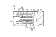
- FIG. 1 is a longitudinal sectional view showing a first embodiment of a damper according to the present invention.
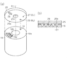
- (A) is an exploded perspective view of the orifice plate and slider of the damper, and
- (b) is a partial sectional view thereof. The whole damper perspective view.
- the exploded perspective view of the orifice plate and slider which shows a 3rd embodiment of the damper concerning the present invention. It is a top view of the state which piled up the orifice plate on the slider, (a) shows the state where there are two orifices, and (b) shows the state where there is one orifice.
- the principal part sectional drawing which shows the modification of the damper which concerns on this invention.
- the principal part sectional drawing which shows the modification of the damper which concerns on this invention.
- the damper is provided between an opening / closing body such as a drawer of a housing facility or a door, and a main body that fixes the opening / closing body so that the opening / closing body can be opened and closed.
- an opening / closing body such as a drawer of a housing facility or a door
- a main body that fixes the opening / closing body so that the opening / closing body can be opened and closed.
- the description will be given as a buffer.
- the damper 10 includes a substantially bottomed cylindrical housing 11 in which silicon oil as a fluid is sealed, and a rod-shaped rod 12 that is movably inserted in the housing 11.
- One end of the rod 12 protrudes from the housing 11, and the end is fixed to the opening / closing body side such as a drawer.
- the rod 12 reciprocates in a direction parallel to the central axis of the housing 11 following the opening / closing operation of the opening / closing body.
- a piston portion 16 slidable in the housing 11 is fitted on the other end portion of the rod 12 accommodated in the housing 11.
- the piston portion 16 includes a piston main body 16 a fixed to the distal end portion of the rod 12, and an orifice plate 25 provided so as to be rotatable closer to the distal end side of the rod 12 than the piston portion 16.
- the piston main body 16a has a sliding portion 17 and a slider 18, and the sliding portion 17 is formed to have a size capable of sliding on the inner peripheral surface of the housing 11. Further, the sliding portion 17 is formed with a fitting hole 17a for fitting the rod 12 therein and a through hole 17b through which silicone oil passes.
- the slider 18 has a double cylindrical structure, and includes an annular groove 18a and a fitting hole 18b provided inside the groove 18a.
- a sliding portion 17 in which the rod 12 is inserted into the fitting hole 17a is fitted in the fitting hole 18b.
- one hole 19 through which silicon oil passes is formed through the bottom of the groove 18a.
- a compression spring 18 c is accommodated in the groove portion 18 a, and the compression spring 18 c biases the slider 18 in a direction away from the sliding portion 17. Therefore, when a large pressing force is not applied to the rod 12, a gap S is provided between the slider 18 and the sliding portion 17.
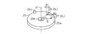
- the orifice plate 25 is in contact with the slider 18 by the compression spring 18c. As shown in FIG. 2, the orifice plate 25 has a substantially disk shape, and a through hole 25h into which the rod 12 is fitted is formed at the center thereof. A first communication hole 26 and a second communication hole 27 that form an orifice OL by communicating with the hole portion 19 of the piston body 16a are formed through the outer side in the radial direction than the through hole 25h. Each communication hole 26, 27 is formed in a circular shape, and the inner diameter ⁇ 1 of the first communication hole 26 is the same as or slightly larger than the inner diameter of the hole portion 19 of the slider 18 and is larger than the inner diameter ⁇ 2 of the second communication hole 27. ing.
- the inner diameter ⁇ 2 of the second communication hole 27 is smaller than the inner diameter of the hole portion 19. That is, the channel cross-sectional area of the first communication hole 26 is larger than the channel cross-sectional area of the second communication hole 27.
- the relative angle ⁇ (the relative angle of the communication holes 26 and 27 in the circumferential direction) formed by the straight lines connecting the centers of the communication holes 26 and 27 and the central axis X1 of the orifice plate 25 is 90. It is less than °.
- the communication holes 26 and 27 are provided at positions overlapping the movement locus of the hole 19 when the piston body 16a is rotated with respect to the orifice plate 25, and can communicate with the hole 19, respectively. Yes. Accordingly, the first communication hole 26 and the hole portion 19, and the second communication hole 27 and the hole portion 19 constitute an orifice OL through which silicon oil passes.
- a fixing structure is provided to be fixed to.
- This fixing structure is a concavo-convex structure that can be fitted to each other, such as a locking piece 25c that protrudes from one side surface 25a of the orifice plate 25, and a fitting hole 11a provided in the side surface of the housing 11 that faces the one side surface 25a. Consists of When the rod 12 is pressed and the piston body 16 a moves to the bottom of the housing 11, the locking piece 25 c is fitted into the fitting hole 11 a of the housing 11. As a result, even if the rod 12 rotates about the axis, the orifice plate 25 is fixed to the housing 11 so as not to rotate.
- connection structure for fixing the orifice plate 25 to the piston body 16a when the piston portion 16 is located at a position other than the end position.
- this connection structure includes a projection 28 that is formed to protrude from the other side surface 25 b of the orifice plate 25, and a meshing portion 18 d that is provided on one side surface 18 s of the slider 18.
- the meshing portion 18d has a plurality of engaging teeth 18t and valleys provided between the engaging teeth 18t, and has a shape that can be engaged with the protrusion 28. Further, the engaging teeth 18t are formed at such a height that their tips do not protrude from the one side surface 18s. Furthermore, the meshing portion 18d is provided over a range of a relative angle ⁇ or more in the circumferential direction of the communication holes 26 and 27 along the circumferential direction of the one side surface 18s. The meshing portion 18 d is pressed against the protrusion 28 by the compression spring 18 c interposed between the sliding portion 17 and the slider 18. The piston body 16a is connected to the orifice plate 25 unless a rotational force that can release the engaged state is applied to the piston portion 16 by the engagement with the protrusions 28 and the meshing portion 18d. There is no rotation.
- the housing 11 is provided with an accumulator mechanism 20 that absorbs the pressure change of the silicone oil caused by the movement of the piston body 16a.
- the accumulator mechanism 20 includes an accumulator 21 made of an elastic member such as an elastomer or a film-like resin, and an inner liner 22 that fixes the accumulator 21 to the housing 11.
- the inner liner 22 has a through hole 22h in the center thereof through which the rod 12 is slidably inserted.
- the inner liner 22 includes a fixing hole 31 on one side surface, and an oil seal 30 that seals the inside of the housing 11 is press-fitted into the fixing hole 31.
- a cap 39 is fixed to the opening of the housing 11 from the outside of the oil seal 30.
- a slit 36 is formed on the other side surface of the inner liner 22 to communicate in the axial direction the space in the housing 11 defined by the inner liner 22 when the inner liner 22 is accommodated in the housing 11. .
- the accumulator 21 is fixed to the inner liner 22 so that the central portion 21a can be displaced by a pressure difference between the inside and the outside.
- silicon oil is pumped from the slit 36 of the inner liner 22 to a space surrounded by the inner liner 22 and the central portion 21a of the accumulator 21.
- this space is filled with silicon oil, the central portion 21a bends outward (in the direction toward the side wall of the housing 11) due to the pressure difference between the inner side and the outer side of the central portion 21a. Absorb.
- the damper 10 When adjusting the braking force of the damper 10, it is adjusted before fixing the damper 10 to the cabinet.
- the damper 10 according to the present embodiment can adjust the magnitude of the braking force in two stages, and the first communication hole 26 and the hole 19 constitute the orifice OL to make the braking force relatively small. And a second mode in which the braking force is increased by forming the orifice OL from the second communication hole 27 and the hole portion 19.
- the rotation alignment mark ML1 stamped on the outer peripheral surface of the portion of the rod 12 protruding from the housing 11 and the cap 39 are provided.
- the first mark M1 is in a matched state.
- the rotational alignment mark ML1 and the first mark M1 are shifted due to an unintended factor, the rotational alignment mark ML1 and the first mark M1 are matched without pressing the rod 12.
- the rotation alignment mark ML1 and the first mark M1 match, as shown in FIG. 5A, the locking piece 25c of the orifice plate 25 and the position of the fitting hole 11a of the housing 11 are in the circumferential direction. At the same position.
- the rod 12 is pushed into the housing 11 with the rotational alignment mark ML1 and the first mark M1 being matched.
- the rod 12 When the rod 12 is further pushed in, the position of the slide alignment mark ML2 of the rod 12 and the side surface of the cap 39 coincide with each other.
- the rod 12 When the damper 10 is attached to the cabinet, the rod 12 is not pushed into the housing 11 until the slide alignment mark ML2 reaches the side surface of the cap 39, and the slide alignment mark ML2 is placed on the side surface of the cap 39.
- the reaching state is limited only when the braking force is changed.
- the locking piece 25c of the orifice plate 25 is fitted into the fitting hole 11a of the housing 11 as shown in FIG. Fitted inside.
- the orifice plate 25 is provided so as to be rotatable with respect to the rod 12, only the orifice plate 25 is fixed so as not to be rotatable with respect to the housing 11, and the piston body 16 a has the rod 12 rotated. For example, it rotates integrally with the rod 12.
- the rod 12 is rotated by a predetermined angle so that the rotational alignment mark ML1 of the rod 12 and the second mark M2 of the cap 39 shown in FIG.
- the predetermined angle at this time is substantially the same as the relative angle ⁇ of the communication holes 26 and 27.
- the rotational force applied to the rod 12 has such a magnitude that the engagement between the engagement portion 18d of the slider 18 and the protrusion 28 can be released.
- the protrusion 28 gets over the crests of the respective engagement teeth 18t of the meshing portion 18d, so that a feeling of moderation (click feeling) accompanying the operation is given.
- the position of the sliding portion 17 in the circumferential direction with respect to the orifice plate 25 is changed, and the hole portion 19 and the communication holes 26, 27 are changed.
- the communication status with is changed. Specifically, as shown in FIG. 5C, the hole 19 communicates with the second communication hole 27 from the first mode in which the hole 19 of the slider 18 communicates with the first communication hole 26. A transition is made to the second mode in which the orifice OL is constituted by the portion 19 and the second communication hole 27.
- the positions of the engaging teeth 18t and the protrusions 28 are adjusted so that the second communication hole 27 and the hole part 19 communicate accurately with each other when the protrusions 28 are engaged with the valleys of 8t. Therefore, the second communication hole 27 and the hole portion 19 can be easily and accurately overlapped with each other.
- the hole portion 19 communicates with the second communication hole 27 the total flow path cross-sectional area (effective flow path cross-sectional area) decreases, and the pressure loss increases, so that the braking force applied to the rod 12 increases.
- the tip of the rod 12 is fixed to the drawer, and the housing 11 is fixed to the cabinet body.
- the rod 12 is moved in the direction of being pulled out from the housing 11 following the movement of the drawer.
- the slider 18 is pressed against the orifice plate 25 by the urging force of the compression spring 18 c, and the slider 18 and the orifice plate 25 move together in the housing 11.
- the silicone oil sealed between the sliding portion 17 and the accumulator mechanism 20 is pumped to the accumulator 21 side through the slit 36 of the inner liner 22,
- the accumulator 21 is bent outward by the pressure inside the silicon oil to absorb the pressure change.
- the orifice plate 25 and the piston main body 16a are coupled to each other by the connecting structure. Therefore, even if a relatively small external force such as fluid resistance of silicon oil or friction with the inner peripheral surface of the housing is applied to the piston portion 16, the relative position between the orifice plate 25 adjusted at the end position and the piston body 16a is shifted. Therefore, the communication state between the communication holes 26 and 27 adjusted at the end position and the hole portion 19 can be maintained.
- the pressing force applied to the drawer is transmitted to the tip of the rod 12.
- the silicon oil existing between the piston portion 16 and the bottom portion of the housing 11 is provided between the orifice OL composed of the second communication hole 27 and the hole portion 19, and between the sliding portion 17 and the slider 18. It moves to the opposite side across the piston main body 16a, that is, the space between the piston main body 16a and the inner liner 22 through the formed gap S.
- a braking force is generated in the rod 12 due to the fluid resistance of the silicon oil, and the pressing force transmitted from the drawer to the rod 12 is attenuated, so that the impact and collision sound between the drawer and the cabinet body can be buffered. it can.
- the silicon oil between the accumulator 21 and the inner liner 22 is sent to the space through the slit 36. Thereby, the bending of the accumulator 21 is eliminated.
- the fixing structure which fixes the orifice plate 25 with respect to the housing 11 so that rotation is impossible is made into the latching piece 25c of the orifice plate 25, and the fitting hole 11a which internally fits this latching piece 25c. It was comprised from the uneven structure which can be mutually fitted. That is, since the locking piece 25c and the fitting hole 11a constituting the fixing structure can be formed integrally with the orifice plate 25 and the housing 11, the number of parts is increased and the apparatus is complicated in order to constitute the fixing structure.
- the magnitude of the braking force can be made variable without making it.
- no special assembly process is required to construct the fixed structure, and the assembly can be performed in the same manner as the damper of the conventional configuration. Therefore, the magnitude of the braking force can be made variable while reducing the assembly process. Can do.
- connection structure for fixing the orifice plate 25 to the piston body 16a when the piston portion 16 is located at a position other than the terminal position is a protrusion formed on the other side surface 25b of the orifice plate 25. 28 and a meshing portion 18 d formed on one side surface 18 s of the slider 18. For this reason, also when the piston part 16 slides in the housing 11, the state which connected the communicating holes 26 and 27 and the hole part 19 in the terminal position can be hold
- two communication holes 26 and 27 having different flow path cross-sectional areas of the orifice plate 25 are respectively connected to one hole portion 19 provided in the piston main body 16a to thereby make the orifice OL Change the total channel cross-sectional area. That is, it is only necessary to form at least one hole 19 in the piston body 16a. For this reason, part of the orifice OL can be provided also in the piston main body 16a in which the space is limited by having the groove portion 18a for accommodating the compression spring 18c inside. Further, since the interval between the communication holes 26 and 27 can be adjusted as appropriate, the interval is too short to make it difficult to rotate the rod 12, or the interval is too large to increase the amount of rotation of the rod 12. Therefore, the operability can be improved by setting the interval between the communication holes 26 and 27 so that the rod 12 can be easily rotated.
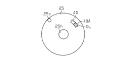
- the hole 19 ⁇ / b> A constituting the orifice OL is formed through one side surface 18 s of the slider 18 in an arc shape and an elongated shape.
- the orifice plate 25 includes an arc-shaped and elongated communication hole 40 that can communicate with the hole 19 of the slider 18.
- the communication hole 40 is formed in substantially the same shape as the hole portion 19A, and all the openings can be opened when superimposed on the hole portion 19A.
- the cap 39 is provided with a first mark M1 at a position that coincides with the rotational alignment mark ML1 of the rod 12 in a state where the entire opening of the hole portion 19 communicates with the communication hole 40.
- the second mark M2 is provided at a position that coincides with the rotational alignment mark ML1 of the rod 12 in a state where the entire opening of the hole portion 19 is closed by the orifice plate 25. Therefore, by rotating the rod 12 within the range from the position where the rotational alignment mark ML1 coincides with the first mark M1 to the position coincident with the second mark M2, the communication of the orifice plate 25 is established.
- the overlapping range between the region excluding the hole 40 and the hole portion 19 can be continuously changed. And by changing the overlapping range in such a manner, the total flow passage sectional area of the orifice OL can be continuously changed, and the pressure loss in the orifice OL can be finely adjusted.
- the second embodiment in addition to the effects described in (1) and (2) of the first embodiment, the following effects can be obtained.
- the second embodiment it is possible to continuously change the total flow path cross-sectional area of the orifice OL by continuously changing the overlapping range of the hole 19 that is closed by the orifice plate 25. it can. For this reason, the magnitude of the braking force of the damper 10 can be finely adjusted.
- the slider 18 has two circular holes 19B and 19C on one side surface 18s thereof. These holes 19 ⁇ / b> B and 19 ⁇ / b> C are arranged on the same circumference around the central axis X ⁇ b> 1 of the slider 18. Moreover, the holes 19B and 19C have the same inner diameter.
- the orifice plate 25 includes a first communication hole 46 and a second communication hole 47 that can communicate with the holes 19B and 19C, respectively.
- Each communication hole 46, 47 has the same inner diameter as the holes 19B, 19C.
- FIG. 9A shows a state in which the first communication hole 46 is communicated with the hole portion 19B and the second communication hole 47 is communicated with the hole portion 19C.
- the number of orifices OL is two, and each includes a hole portion 19B and a first communication hole 46, and a hole portion 19C and a second communication hole 47.
- the total channel cross-sectional area of the orifice OL at this time is the channel cross-sectional area of the orifice OL composed of the hole 19B and the first communication hole 46, and the channel of the orifice OL composed of the hole 19C and the second communication hole 47. It is the sum of the cross-sectional areas.
- the total channel cross-sectional area of the orifice OL can be changed also by changing the number of the holes 19B and 19C communicated with the communication holes 46 and 47 in this way. Therefore, according to the third embodiment, the following effects can be obtained in addition to the effects described in (1) and (2) of the first embodiment.
- the total channel cross-sectional area of the orifice OL is changed by changing the number of the holes 19B and 19C communicated with the communication holes 46 and 47 among the two holes 19B and 19C. To do. Therefore, the number of holes formed in the slider 18 and the inner diameter, the number of communication holes formed in the orifice plate 25 and the inner diameter are changed, and the combination of the holes and the communication holes increases the braking force. Thus, the degree of freedom of the apparatus can be improved.
- the fluid contained in the damper 10 is silicon oil, but any fluid that generates viscous resistance may be used.
- fluid made of other materials such as ester oil or gas such as inert gas may be used. It is also possible to use it.
- the communication hole forming member is configured from the disc-shaped orifice plate 25, but may be configured from a sliding member having other shapes such as a columnar shape.
- the piston main body 16a is configured by the sliding portion 17 and the slider 18, but may not be configured by two members but may be integrally formed.
- the accumulator mechanism that absorbs the pressure change in the housing may be configured by a mechanism other than the accumulator 21 and the inner liner 22.
- the fitting hole 11 a of the housing 11 may be provided at a position other than the bottom as long as it is the end position of the slidable range of the piston portion 16. For example, you may make it provide in the wall part which is the position before the bottom part, and protrudes from the internal peripheral surface of a housing.
- the relative angle ⁇ formed by the straight line connecting the center of the first communication hole 26 and the central axis X1 and the straight line connecting the center of the second communication hole 27 and the central axis X1 is 90 although it is less than 0 °, it may be 90 ° or more.
- the communicating hole 40 was made into circular arc shape and an elongate shape, as long as it has the shape and area which can change the opening area of the hole part 19 with the overlapping range with the hole part 19, it is. Good.
- the holes 19B and 19C have the same inner diameter, but may have different inner diameters.
- the communication holes 46 and 47 have the same inner diameter, they may have different inner diameters.
- five modes for adjusting the braking force can be selected. That is, only the hole 19B is opened, the mode in which the communication hole 46 communicates with the hole 19B, the mode in which the communication hole 47 communicates with the hole 19B, and the state in which only the hole 19C is opened.
- the fixing structure is configured by an uneven structure such as the locking piece 25c and the fitting hole 11a.
- the piston plate 16 is disposed at the terminal position and the orifice plate 25 can be fixed so as not to rotate.
- Other configurations may be used as long as they are present.
- an uneven structure of another shape for example, instead of the locking piece 25c, an annular protrusion is formed on the orifice plate 25, and an annular recess in which the annular protrusion can be fitted is formed on the housing 11.
- the orifice plate 25 may be provided with a recess, and the housing 11 may be provided with a protrusion.
- a fixing structure other than the concave-convex structure for example, as shown in FIG.
- It may be configured from an inclined surface that can be contacted with each other only.
- the orifice plate 25 When the orifice plate 25 is pressed while being in contact with the side surface 50 of the housing 11, the orifice plate 25 becomes difficult to follow even if the rod 12 is rotated.
- magnets that attract each other may be provided on the bottom of the housing 11 and one side surface 25a of the orifice plate 25. The attractive force acting between the magnets is set so as not to be released by the rotational force of the rod 12.
- one projection 28 is formed on the orifice plate 25 as a connecting structure.
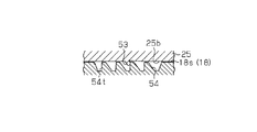
- the meshing portion 18d may have a ratchet structure as shown in FIG. That is, as shown in FIG. 11, a meshing portion 54 composed of a plurality of ratchet teeth 54 t is provided on one side surface 18 s of the slider 18, and the other side surface 25 b of the orifice plate 25 moves relative to the meshing portion 54 only in one direction.
- a possible claw portion 53 may be provided.
- the orifice plate 25 is made stronger than the piston portion 16 when the piston portion 16 moves in the housing 11 or the like. Can be linked.
- damper 10 was demonstrated as a damper provided between drawers, doors, etc., such as a cabinet, and the fixed side member which fixes this, the use of the damper of the present invention is not limited to this. As long as it has the opening / closing body and the fixing member, it may be used for automobiles, building fixtures, etc., in addition to furniture such as cabinets and housing equipment.
- the entire contents of the specification, claims, drawings and abstract of Japanese Patent Application No. 2011-016539 filed on January 28, 2011 are cited herein as disclosure of the specification of the present invention. Incorporated.
Landscapes
- Engineering & Computer Science (AREA)
- General Engineering & Computer Science (AREA)
- Mechanical Engineering (AREA)
- Fluid-Damping Devices (AREA)
Abstract
ピストン部は、流体を通過させるための孔部が少なくとも1つ設けられてロッドに固定されるピストン本体と、孔部と連通することでオリフィスを構成する連通孔が少なくとも1つ設けられロッドに対して回動可能に設けられるオリフィスプレートとを備え、オリフィスプレートとハウジングとには、オリフィスプレートをハウジングに対して固定可能な固定構造が設けられるとともに、オリフィスプレートが固定構造によりハウジングに対して固定された状態で、ロッドを回動させてオリフィスプレートに対するピストン本体の周方向における位置を変更することにより孔部と連通孔との連通状態を変更して、オリフィスの総流路断面積を可変とする。
Description
この発明は、流体を封入したハウジング内でロッドと一体をなすピストンを摺動させるダンパーに関する。
従来より、外部から加えられた衝撃を緩衝するダンパーとしては、流体を封入したハウジング内でロッドと一体をなすピストン部を摺動させる、いわゆるピストンダンパー(又はピストン式ダンパー)が知られている。この構成のダンパーは、ピストン部に、該ピストン部によって2分割されたハウジング内の空間を連通するオリフィスを設け、ピストン部がハウジング内を摺動する際の流体抵抗により制動力を発生させている。
このような構成のダンパーにおいて制動力を変更する場合には、ピストン部を、異なるオリフィス径を有する新たなピストン部に交換する必要があり、手間及びコスト高を招来していた。
一方、部品交換をすることなく、制動力の大きさを調整するダンパーが知られている(例えば、特許文献1参照)。このダンパーでは、シリンダ内に挿入されるピストンロッドの内側に、オリフィス径を変更可能な調整ロッドを備えている。調整ロッドは、その一端に複数の異径オリフィスを穿設したオリフィスプレートを係合し、他端にはアジャスタを備え、このアジャスタを介して回動されるようになっている。オリフィスプレートには、油孔を有するプレートが当接しており、油孔を、異径オリフィスの一つに適合させることにより、流動抵抗を変えて制動力(反発荷重)を調整している。
しかし、従来構成の上記ダンパーは、ピストンロッドの内側に調整ロッドを挿入した二重構造を採用しているため、装置が複雑化している。従って、部品点数が多いだけでなく、組み立て時には、ピストンロッドの内側に調整ロッドを挿入し、且つピストンロッドの両端に、オリフィスプレート及び油孔を有するプレートと、アジャスタとをそれぞれ取り付けるといった煩雑な工程を踏まなければならず、組立工数も多くなるといった問題がある。
本発明は、こうした実情に鑑みてなされたものであり、その目的は、装置の複雑化を抑制しつつ、制動力の大きさを可変とすることができるダンパーを提供することにある。
また、本発明の別の目的は、部品点数及び組立工数を低減しつつ、制動力の大きさを可変とすることができるダンパーを提供することにある。
また、本発明の別の目的は、部品点数及び組立工数を低減しつつ、制動力の大きさを可変とすることができるダンパーを提供することにある。
上記問題点を解決するために、本発明は、流体を封入したハウジングと、前記ハウジング内に摺動可能に設けられたピストン部と、前記ピストン部に連結されたロッドとを備え、前記ロッドの移動に伴う流体抵抗により制動力を発生させるダンパーにおいて、前記ピストン部は、前記流体を通過させるための孔部が少なくとも1つ設けられて前記ロッドに固定されるピストン本体と、前記孔部と連通することでオリフィスを構成する連通孔が少なくとも1つ設けられ前記ロッドに対して回動可能に設けられる連通孔形成部材とを備え、前記連通孔形成部材と前記ハウジングとには、前記連通孔形成部材を前記ハウジングに対して固定可能な固定構造が設けられるとともに、前記連通孔形成部材が前記固定構造により前記ハウジングに対して固定された状態で前記ロッドを回動させることにより前記孔部と前記連通孔との連通状態を変更して、前記オリフィスの総流路断面積を可変とすることを要旨とする。
上記構成によれば、連通孔形成部材とハウジングとには、連通孔形成部材をハウジングに対して固定する固定構造が設けられているので、ロッドをハウジングに対して押し込み、さらに回動させるといった操作で、ロッドに連結されたピストン本体を連通孔形成部材に対して回動させることができる。そして、そのピストン本体の回動により、連通孔とピストン本体の孔部との連通状態を変更してオリフィスの総流路断面積を変えることで、制動力の大きさを可変とすることができる。即ち、ピストン本体の周方向における位置を変更するための構成は、ピストン本体とハウジングとに形成される固定構造のみであるため、装置の複雑化を抑制しつつ、制動力の大きさを可変とすることができる。また、ピストン本体の周方向における位置を変更する構成のための部品点数及び組立工数を増加させることなく、制動力の大きさを可変とすることができる。
本発明によるダンパーにおいて、前記固定構造は、前記連通孔形成部材の一側面と、該一側面に対向する前記ハウジングの側面に形成された互いに嵌合可能な凹凸構造であることが好ましい。
上記構成によれば、固定構造は、互いに嵌合可能な凹凸構造であるため、連結孔形成部材及びハウジングに一体に形成することが可能となり、装置の複雑化を抑制することができる。
本発明によるダンパーにおいて、前記ピストン本体と前記連通孔形成部材とには、該連通孔形成部材が前記固定構造により固定されていない際に前記連通孔形成部材を前記ピストン本体に対して連結する連結構造が設けられていることが好ましい。
上記構成によれば、ピストン部が終端位置以外の位置にある際に、上記連結構造により、連通孔形成部材がピストン本体に対して固定されるので、ピストン部がハウジング内を摺動する際にも、終端位置で連通孔と孔部とを連通させた状態を保持することができる。
本発明によるダンパーにおいて、前記連通孔形成部材は、流路断面積が互いに異なる複数の前記連通孔を備え、前記ピストン本体を前記ハウジングに対して固定された前記連通孔形成部材に対して回動させて、前記ピストン本体の前記孔部に前記各連通孔をそれぞれ連通することにより前記オリフィスの総流路断面積を変更することが好ましい。
上記構成によれば、連通孔形成部材は、流路断面積が互いに異なる複数の連通孔を、ピストン本体の孔部にそれぞれ連通させることでオリフィスの総流路断面積を変更するため、制動力を可変とするためにはピストン本体に孔部を最低限1つだけ設ければよい。このため、孔部が形成されるスペースが限られたピストン本体であっても、制動力を可変とすることができる。
本発明によるダンパーにおいて、前記連通孔形成部材は、前記孔部の少なくとも一部を閉塞可能な閉塞部を備え、前記連通孔と前記孔部とを連通させるとともに前記閉塞部と前記孔部との重複範囲を変更することにより前記オリフィスの総流路断面積を変更することが好ましい。
上記構成によれば、孔部のうち閉塞部によって閉塞される重複範囲を変更することによりオリフィスの総流路断面積を連続的に変更することができる。このため、制動力の大きさの微調整が可能となる。
本発明によるダンパーにおいて、前記ピストン本体には複数の前記孔部が設けられるとともに、前記連通孔形成部材には複数の前記連通孔が設けられ、前記連通孔に連通される前記孔部の個数を変更することにより前記オリフィスの総流路断面積を変更することが好ましい。
上記構成によれば、孔部及び連通孔はそれぞれ複数設けられ、連通孔に連通される孔部の個数を変更することによりオリフィスの総流路断面積を変更するので、孔部の個数及び連通孔の個数を変えることで、制動力の大きさを多段階的に変更可能となり、装置の自由度を向上することができる。
以上のように、この発明によれば、装置の複雑化を抑制しつつ、制動力の大きさを可変とするダンパーを提供することができるという効果を奏する。また、この発明によれば、部品点数及び組立工数を低減しつつ、制動力の大きさを可変とするダンパーを提供することができるという効果を奏する。
(第1実施形態)
以下、本発明に係るダンパーを具体化した一実施形態を図1~図5(d)にしたがって説明する。本実施形態では、ダンパーを、住宅設備の引出しや扉等の開閉体と、開閉体を開閉可能に固定する本体との間に設けられ、開閉体と本体とが衝突する際の衝撃や騒音を緩衝するものとして説明する。
以下、本発明に係るダンパーを具体化した一実施形態を図1~図5(d)にしたがって説明する。本実施形態では、ダンパーを、住宅設備の引出しや扉等の開閉体と、開閉体を開閉可能に固定する本体との間に設けられ、開閉体と本体とが衝突する際の衝撃や騒音を緩衝するものとして説明する。
図1に示すように、ダンパー10は、流体としてのシリコンオイルを封入した略有底円筒状のハウジング11と、ハウジング11内を移動可能に貫挿された棒状のロッド12とを有する。ロッド12の一方の端部はハウジング11から突出し、該端部は引出し等の開閉体側に固定される。そしてロッド12は、その開閉体の開閉動作に従動して、ハウジング11の中心軸と平行な方向に往復動する。
また、ロッド12のうち、ハウジング11に収容された他方の端部には、ハウジング11内を摺動可能なピストン部16が外嵌されている。ピストン部16は、ロッド12の先端部に固定されたピストン本体16aと、ピストン部16よりもロッド12の先端側に回動可能に設けられたオリフィスプレート25とを有している。
さらにピストン本体16aは、摺動部17とスライダ18とを有しており、摺動部17は、ハウジング11の内周面を摺動可能な大きさに形成されている。また、摺動部17には、ロッド12を内嵌するための嵌合孔17aと、シリコンオイルを通過させる貫通孔17bとがそれぞれ貫通形成されている。
スライダ18は、二重の筒状構造を有し、環状の溝部18aと、溝部18aの内側に設けられた嵌合孔18bとを備えている。嵌合孔18bには、ロッド12を嵌合孔17aに貫挿した摺動部17が内嵌されている。また、溝部18aの底部には、シリコンオイルを通過させる孔部19が1つ貫通形成されている。さらに溝部18aには圧縮ばね18cが収容されており、該圧縮ばね18cは、スライダ18を摺動部17に対して離間させる方向に付勢している。従って、ロッド12に大きな押圧力が加えられない場合には、スライダ18と摺動部17との間には隙間Sが設けられた状態となっている。
また、オリフィスプレート25は、圧縮ばね18cによってスライダ18と当接した状態となっている。図2に示すように、このオリフィスプレート25は、略円盤状をなし、その中央にはロッド12を内嵌する貫挿孔25hが形成されている。この貫挿孔25hよりも径方向外側には、ピストン本体16aの孔部19と連通することでオリフィスOLを構成する第1連通孔26及び第2連通孔27が貫通形成されている。各連通孔26,27は、円形状に形成され、第1連通孔26の内径φ1は、スライダ18の孔部19の内径と同一又は若干大きく、第2連通孔27の内径φ2よりも大きくなっている。また、第2連通孔27の内径φ2は、孔部19の内径よりも小さい。即ち、第1連通孔26の流路断面積は、第2連通孔27の流路断面積よりも大きくなっている。また本実施形態では、各連通孔26,27の中心とオリフィスプレート25の中心軸X1とを結ぶ各直線がなす相対角度α(円周方向における各連通孔26,27の相対角度)は、90°未満である。
また、各連通孔26,27は、ピストン本体16aを、オリフィスプレート25に対して回動させた際の孔部19の移動軌跡と重なる位置に設けられ、孔部19にそれぞれ連通可能となっている。従って、第1連通孔26及び孔部19、第2連通孔27及び孔部19により、シリコンオイルを通過させるオリフィスOLが構成される。
また、オリフィスプレート25の一側面25aとハウジング11の底部とには、ピストン部16が摺動可能範囲の底部側の終端位置に移動した際に、オリフィスプレート25をハウジング11に対して回動不能に固定する固定構造が設けられている。この固定構造は、オリフィスプレート25の一側面25aに突出形成された係止片25cと、その一側面25aに対向するハウジング11の側面に設けられた嵌合孔11aといった互いに嵌合可能な凹凸構造から構成される。ロッド12が押圧されて、ピストン本体16aがハウジング11の底部に移動すると、その係止片25cがハウジング11の嵌合孔11aに内嵌される。その結果、ロッド12が軸中心に回動しても、オリフィスプレート25は回動不能にハウジング11に固定される。
また、オリフィスプレート25とスライダ18とが互いに対向する面には、ピストン部16が上記終端位置以外の位置にある際に、オリフィスプレート25をピストン本体16aに対して固定する連結構造が設けられている。この連結構造は、図3(a)に示すように、オリフィスプレート25の他側面25bに突出形成された突起28と、スライダ18の一側面18sに設けられた噛合部18dとから構成される。
図3(b)に示すように、噛合部18dは、複数の係合歯18tと各係合歯18tの間に設けられた谷部を有し、突起28と係合可能な形状をなす。また、係合歯18tは、その先端が一側面18sから突出しないような高さに形成されている。さらに、噛合部18dは、一側面18sの円周方向に沿って、各連通孔26,27の周方向における相対角度α以上の範囲に亘って設けられている。この噛合部18dは、摺動部17とスライダ18との間に介在する上記圧縮ばね18cによって、突起28に圧接されている。これらの突起28及び噛合部18dとの係合により、その係合状態を解除可能な大きさの回転力がピストン部16に加えられない限り、ピストン本体16aはオリフィスプレート25に対して連結され、回動することがない。
また、図1に示すように、ハウジング11には、ピストン本体16aが移動することで生じるシリコンオイルの圧力変化を吸収するアキュムレータ機構20が設けられている。アキュムレータ機構20は、エラストマーやフィルム状の樹脂等の弾性部材からなるアキュムレータ21と、アキュムレータ21をハウジング11に固定するインナーライナー22とを備えている。
インナーライナー22は、その中央にロッド12が摺動可能に貫挿される貫通孔22hを備えている。また、インナーライナー22は、一方の側面に固定穴31を備え、該固定穴31には、ハウジング11内を密封するオイルシール30が圧入されている。また、オイルシール30の外側からは、キャップ39がハウジング11の開口部に対して固定されている。さらにインナーライナー22の他方の側面には、インナーライナー22がハウジング11内に収容された際に、インナーライナー22によって区切られたハウジング11内の空間を軸方向に連通するスリット36が形成されている。
アキュムレータ21は、その中央部21aが、内側と外側との圧力差によって変位可能となるようにインナーライナー22に固定されている。ピストン部16が、ハウジング11の底部から開口部側に向かって移動すると、インナーライナー22のスリット36から、インナーライナー22とアキュムレータ21の中央部21aとにより囲まれた空間にシリコンオイルが圧送される。この空間にシリコンオイルが満たされると、中央部21aの内側と外側との圧力差により、中央部21aが外側(ハウジング11の側壁部に向かう方向)に向かって撓み、ハウジング11内の圧力変化を吸収する。
次に、上記ダンパー10の作用について図4及び図5(a)~(d)にしたがって説明する。尚、ここではロッド12の先端を、キャビネットの引出しに直接的又は間接的に固定し、ハウジング11をキャビネット本体(いずれも図示略)に固定する場合を例にして説明する。
ダンパー10の制動力を調整する場合、ダンパー10をキャビネットに固定する前にその調整を行う。本実施形態のダンパー10は、制動力の大きさを2段階に調整可能であり、第1連通孔26と孔部19とからオリフィスOLを構成することにより制動力を比較的小さくする第1のモードと、第2連通孔27と孔部19とからオリフィスOLを構成することにより制動力を大きくする第2のモードとを有する。
ロッド12が第1のモードとなる位置にあるとき、図4に示すように、ロッド12のうちハウジング11から突出した部分の外周面に刻印された回転位置合わせマークML1と、キャップ39に設けられた第1のマークM1とが合致した状態にある。意図しない要因により回転位置合わせマークML1と第1のマークM1とがずれている場合には、ロッド12を押圧しないまま、回転位置合わせマークML1と第1のマークM1とを合致させる。回転位置合わせマークML1と第1のマークM1とが合致すると、図5(a)に示すように、オリフィスプレート25の係止片25cとハウジング11の嵌合孔11aの位置とが、周方向において同位置となる。そして、第1のモードから第2のモードにする場合には、回転位置合わせマークML1と第1のマークM1とを合致させた状態のまま、ロッド12をハウジング11に押し込んでいく。
さらにロッド12を押し込んでいくと、ロッド12のスライド位置合わせマークML2とキャップ39の側面との位置が合致した状態となる。尚、ダンパー10がキャビネットに取り付けられた際に、ロッド12がスライド位置合わせマークML2がキャップ39の側面に到達するまでハウジング11に押し込まれることはなく、スライド位置合わせマークML2がキャップ39の側面に到達する状態は、制動力を変更する場合のみに限られる。
ロッド12がスライド位置合わせマークML2がキャップ39の側面に到達するまでハウジング11に押し込まれると、図5(b)に示すように、オリフィスプレート25の係止片25cがハウジング11の嵌合孔11aに内嵌される。上記したようにオリフィスプレート25はロッド12に対して回動可能に設けられているため、オリフィスプレート25のみがハウジング11に対して回動不能に固定され、ピストン本体16aは、ロッド12が回転すれば、ロッド12と一体に回転する。
さらに、ロッド12の回転位置合わせマークML1と図4に示すキャップ39の第2のマークM2とを合致させるように、ロッド12を所定角度だけ回転させる。この際の所定角度は、連通孔26,27の相対角度αとほぼ同じである。また、ロッド12に印加される回転力は、スライダ18の噛合部18dと突起28の係合を解除可能な大きさである。また、ロッド12を回転させることにより、突起28が噛合部18dの各係合歯18tの山部を乗り越えていくので、操作に伴う節度感(クリック感)が与えられる。
ロッド12を、回転位置合わせマークML1と第2のマークM2とが合致するまで回転させると、オリフィスプレート25に対する摺動部17の周方向における位置が変更され、孔部19と連通孔26,27との連通状態が変更される。具体的には、図5(c)に示すように、スライダ18の孔部19が第1連通孔26に連通した第1のモードから、孔部19が第2連通孔27に連通し、孔部19と第2連通孔27とからオリフィスOLが構成される第2のモードに移行する。この際、上記係合歯18t及び突起28の位置は、係合は8tの谷部に突起28が係合したところで、第2連通孔27と孔部19とが正確に連通するように調整されているため、第2連通孔27と孔部19とを、操作上容易に、且つ正確に重ね合わせることができる。第2連通孔27に孔部19が連通すると、その総流路断面積(有効流路断面積)が小さくなり、圧力損失が大きくなるため、ロッド12に加わる制動力は大きくなる。
このように制動力を調整すると、ロッド12の先端を引き出しに固定し、ハウジング11をキャビネット本体に固定する。そして、引出しがキャビネット本体から引き出されると(引出しの開操作)、ロッド12は引出しの移動に従動して、ハウジング11から引き出される方向に移動する。このとき圧縮ばね18cの付勢力により、スライダ18はオリフィスプレート25に圧接され、スライダ18及びオリフィスプレート25はハウジング11内を一体となって移動する。
また、ロッド12が引き出されると、上記したように、摺動部17とアキュムレータ機構20との間に封入されていたシリコンオイルは、インナーライナー22のスリット36を介してアキュムレータ21側に圧送され、アキュムレータ21はシリコンオイルによる内側の圧力によって、外側に撓んで圧力変化を吸収する。
このようにピストン部16がハウジング11内を摺動する際、上記連結構造によりオリフィスプレート25とピストン本体16aとは互いに結合されている。このため、シリコンオイルの流体抵抗やハウジング内周面との摩擦等といった比較的小さい外力がピストン部16に印加されても、終端位置で調整したオリフィスプレート25とピストン本体16aとの相対位置がずれたりすることがなく、終端位置で調整された連通孔26,27と孔部19との連通状態を保持することができる。
そして、開状態にある引出しが、キャビネット本体に対して押し込まれると(引出しの閉操作)、ロッド12の先端部に、引出しに対して加えられた押圧力が伝達される。その結果、ピストン部16とハウジング11の底部との間に存在するシリコンオイルは、第2連通孔27及び孔部19から構成されるオリフィスOLと、摺動部17とスライダ18との間に設けられた隙間Sを介して、ピストン本体16aを挟んだ反対側、即ちピストン本体16aとインナーライナー22との間の空間に移動する。この際、シリコンオイルの流体抵抗によりロッド12に制動力が発生し、引出しからロッド12に伝達される押圧力が減衰されることで、引出しとキャビネット本体との衝撃や衝突音を緩衝することができる。また、ロッド12が押し込まれるに伴い、アキュムレータ21とインナーライナー22との間のシリコンオイルが、スリット36を介して、該空間に送出される。これにより、アキュムレータ21の撓みが解消される。
また、引出しをキャビネット本体へ急激に押し込んだ場合には、ロッド12に圧縮ばね18cの付勢力を上回る押圧力が加わるので、摺動部17がスライダ18に押し付けられ、隙間Sが無くなる。その結果、ピストン本体16a内における圧力損失が増大するため、ロッド12に加わる制動力が増大されて、引出しとキャビネット本体とが勢いよく衝突することを防止することができる。
第1実施形態によれば、以下のような効果を得ることができる。
(1)第1実施形態では、オリフィスプレート25をハウジング11に対して回動不能に固定する固定構造を、オリフィスプレート25の係止片25c及び該係止片25cを内嵌する嵌合孔11aといった互いに嵌合可能な凹凸構造から構成した。即ち、固定構造を構成する係止片25c及び嵌合孔11aを、オリフィスプレート25及びハウジング11に一体に形成することができるので、固定構造を構成するために部品点数を増やしたり、装置を複雑化させることなく、制動力の大きさを可変とすることができる。また、固定構造を構築するために、特別な組立工程は必要なく、従来構成のダンパーと同様に組立を行うことができるため、組立工程を低減させつつ、制動力の大きさを可変とすることができる。
(1)第1実施形態では、オリフィスプレート25をハウジング11に対して回動不能に固定する固定構造を、オリフィスプレート25の係止片25c及び該係止片25cを内嵌する嵌合孔11aといった互いに嵌合可能な凹凸構造から構成した。即ち、固定構造を構成する係止片25c及び嵌合孔11aを、オリフィスプレート25及びハウジング11に一体に形成することができるので、固定構造を構成するために部品点数を増やしたり、装置を複雑化させることなく、制動力の大きさを可変とすることができる。また、固定構造を構築するために、特別な組立工程は必要なく、従来構成のダンパーと同様に組立を行うことができるため、組立工程を低減させつつ、制動力の大きさを可変とすることができる。
(2)第1実施形態では、ピストン部16が終端位置以外の位置にある際にオリフィスプレート25をピストン本体16aに対して固定する連結構造を、オリフィスプレート25の他側面25bに形成された突起28と、スライダ18の一側面18sに形成された噛合部18dとから構成した。このため、ピストン部16がハウジング11内を摺動する際にも、終端位置で連通孔26,27と孔部19とを連通させた状態を保持することができる。また、ピストン本体16aは、オリフィスプレート25に対して周方向における両方の方向に回動可能であるため、孔部19と連通孔26,27との連通状態を切り替えるための操作量(回転量)を少なくすることができる。さらに、突起28が噛合部18dに係合(噛合)しながら移動することで、節度感(クリック感)を付与することができ、孔部19と連通孔26,27との位置合わせも容易となる。
(3)第1実施形態では、オリフィスプレート25の流路断面積が互いに異なる2つの連通孔26,27を、ピストン本体16aに設けられた1つの孔部19にそれぞれ連通させることでオリフィスOLの総流路断面積を変更する。即ち、ピストン本体16aには、最低限1個の孔部19を形成すればよい。このため、圧縮ばね18cを収容するための溝部18aを内側に有することでスペースが限られたピストン本体16aにもオリフィスOLの一部を設けることができる。また、各連通孔26,27の間隔は適宜調整可能であるため、間隔が短すぎてロッド12の回動操作が難しくなったり、間隔が大きすぎてロッド12の回動操作量が大きくなったりすることなく、各連通孔26,27の間隔を、ロッド12を回動操作しやすいような間隔にして操作性を向上することができる。
(第2実施形態)
次に、本発明を具体化した第2実施形態を図6及び図7にしたがって説明する。尚、第2実施形態は、第1実施形態のピストン部の一部を変更したのみの構成であるため、同様の部分については同一符号を付してその詳細な説明を省略する。
次に、本発明を具体化した第2実施形態を図6及び図7にしたがって説明する。尚、第2実施形態は、第1実施形態のピストン部の一部を変更したのみの構成であるため、同様の部分については同一符号を付してその詳細な説明を省略する。
図6に示すように、オリフィスOLを構成する孔部19Aは、スライダ18の一側面18sに、円弧状且つ細長状に貫通形成されている。また、オリフィスプレート25は、スライダ18の孔部19に連通可能な円弧状且つ細長状の連通孔40を備えている。連通孔40は、孔部19Aとほぼ同じ形状に形成され、孔部19Aに重ね合わされた際にその開口全てを開放可能となっている。
孔部19の開口が連通孔40を介して全開放されている状態から、所定の角度だけピストン本体16aを回転させると、図7に示すように、孔部19の一部が、オリフィスプレート25によって閉塞され、孔部19の他方の一部のみが連通孔40に連通された状態になる。即ち、オリフィスプレート25のうち連通孔40を除く領域が、孔部19の少なくとも一部を閉塞する閉塞部として機能する。
また、キャップ39には、孔部19の全開口が連通孔40に連通する状態で、ロッド12の回転位置合わせマークML1と合致する位置に第1のマークM1が設けられている。さらに、孔部19の全開口がオリフィスプレート25によって閉塞された状態で、ロッド12の回転位置合わせマークML1と合致する位置に第2のマークM2が設けられている。従って、ロッド12を、その回転位置合わせマークML1が第1のマークM1と合致する位置から、第2のマークM2と合致する位置までの範囲内で回動させることにより、オリフィスプレート25のうち連通孔40を除く領域と孔部19との重複範囲を連続的に変更することができる。そしてそのように重複範囲を変更することにより、オリフィスOLの総流路断面積を連続的に変更することが可能となり、オリフィスOLにおける圧力損失の微調整が可能となる。
従って、第2実施形態によれば、第1実施形態の(1)及び(2)に記載の効果に加えて以下の効果を得ることができる。
(4)第2実施形態によれば、孔部19のうちオリフィスプレート25によって閉塞される重複範囲を連続的に変更することにより、オリフィスOLの総流路断面積を連続的に変更することができる。このため、ダンパー10の制動力の大きさの微調整が可能となる。
(4)第2実施形態によれば、孔部19のうちオリフィスプレート25によって閉塞される重複範囲を連続的に変更することにより、オリフィスOLの総流路断面積を連続的に変更することができる。このため、ダンパー10の制動力の大きさの微調整が可能となる。
(第3実施形態)
次に、本発明を具体化した第2実施形態を図8~図9(b)にしたがって説明する。尚、第3実施形態は、第1実施形態のピストン部の一部を変更したのみの構成であるため、同様の部分については同一符号を付してその詳細な説明を省略する。
次に、本発明を具体化した第2実施形態を図8~図9(b)にしたがって説明する。尚、第3実施形態は、第1実施形態のピストン部の一部を変更したのみの構成であるため、同様の部分については同一符号を付してその詳細な説明を省略する。
図8に示すように、スライダ18は、その一側面18sに、2つの円形状の孔部19B,19Cを有している。これらの孔部19B,19Cは、スライダ18の中心軸X1を中心とした同じ円周上に配置されている。また、孔部19B,19Cは同じ内径を有している。
また、オリフィスプレート25は、各孔部19B,19Cにそれぞれ連通可能な第1連通孔46及び第2連通孔47を備えている。各連通孔46,47は、孔部19B,19Cと同じ内径を有している。
図9(a)は、第1連通孔46を孔部19Bに連通させ、第2連通孔47を孔部19Cに連通させた状態を示している。この際、オリフィスOLは、2つとなり、孔部19B及び第1連通孔46と,孔部19C及び第2連通孔47とからそれぞれ構成される。このときのオリフィスOLの総流路断面積は、孔部19B及び第1連通孔46からなるオリフィスOLの流路断面積と、孔部19C及び第2連通孔47とからなるオリフィスOLの流路断面積との和になる。
この状態からピストン本体16aをオリフィスプレート25に対して、例えば上記相対角度αだけ回転させると、図9(b)に示すように、第2連通孔47が孔部19Bに連通し、孔部19Cはオリフィスプレート25によって完全に閉塞された状態となる。このため、オリフィスOLとして機能するのは孔部19B及び第2連通孔47のみとなり、このときのオリフィスOLの総流路断面積は、孔部19B及び第2連通孔47からなるオリフィスOLの流路断面積となる。
従って、このように各連通孔46,47に連通される孔部19B,19Cの個数を変更することでも、オリフィスOLの総流路断面積を変更することができる。
従って、第3実施形態によれば、第1実施形態の(1)及び(2)に記載の効果に加えて以下の効果を得ることができる。
従って、第3実施形態によれば、第1実施形態の(1)及び(2)に記載の効果に加えて以下の効果を得ることができる。
(5)第3実施形態では、2つの孔部19B,19Cのうち、連通孔46,47に連通される孔部19B,19Cの個数を変更することによりオリフィスOLの総流路断面積を変更する。このため、スライダ18に形成される孔部の個数や内径、オリフィスプレート25に形成される連通孔の個数や内径を変更し、各孔部と各連通孔とを組み合わせることで、制動力の大きさを多段階的に変更可能となり、装置の自由度を向上することができる。
尚、上記実施形態は以下のように変更してもよい。
・ダンパー10に収容される流体は、シリコンオイルとしたが、粘性抵抗を発生する流体であれば良く、例えば、エステル系のオイルや、不活性ガス等の気体等、他の材料からなる流体を用いることも可能である。
・ダンパー10に収容される流体は、シリコンオイルとしたが、粘性抵抗を発生する流体であれば良く、例えば、エステル系のオイルや、不活性ガス等の気体等、他の材料からなる流体を用いることも可能である。
・上記各実施形態では、連通孔形成部材を円盤状のオリフィスプレート25から構成したが、円柱状等その他の形状の摺動部材から構成してもよい。
・上記各実施形態では、ピストン本体16aは、摺動部17とスライダ18とから構成したが、2つの部材から構成せず、一体に形成してもよい。
・上記各実施形態では、ピストン本体16aは、摺動部17とスライダ18とから構成したが、2つの部材から構成せず、一体に形成してもよい。
・上記各実施形態では、ハウジング内の圧力変化を吸収するアキュムレータ機構は、アキュムレータ21及びインナーライナー22以外の機構から構成してもよい。
・上記各実施形態では、ハウジング11の嵌合孔11aは、ピストン部16の摺動可能範囲の終端位置であれば、底部以外の位置に設けられていてもよい。例えば、底部の手前の位置であって、ハウジングの内周面から突出形成された壁部に設けるようにしてもよい。
・上記各実施形態では、ハウジング11の嵌合孔11aは、ピストン部16の摺動可能範囲の終端位置であれば、底部以外の位置に設けられていてもよい。例えば、底部の手前の位置であって、ハウジングの内周面から突出形成された壁部に設けるようにしてもよい。
・第1実施形態では、連通孔の内径を互いに異なる大きさとしたが、連通孔の形状を変更することにより流路断面積を変更するようにしてもよい。
・第1実施形態では、第1連通孔26の中心と上記中心軸X1とを結ぶ直線と、第2連通孔27の中心と上記中心軸X1とを結ぶ直線とがなす相対角度αは、90°未満であるとしたが、90°以上でもよい。
・第1実施形態では、第1連通孔26の中心と上記中心軸X1とを結ぶ直線と、第2連通孔27の中心と上記中心軸X1とを結ぶ直線とがなす相対角度αは、90°未満であるとしたが、90°以上でもよい。
・第2実施形態では、連通孔40を、円弧状且つ細長状の形状としたが、孔部19との重複範囲によって孔部19の開口面積を可変である形状及び面積を有していればよい。例えば、オリフィスプレート25に形成された切欠きから構成してもよいし、円形状又は楕円形状の貫通孔から構成してもよい。
・第3実施形態では、各孔部19B,19Cは同じ内径を有するとしたが、異なる内径でもよい。また、各連通孔46,47は同じ内径を有するとしたが、異なる内径でもよい。例えば、各孔部19B,19Cの内径が異なり、且つ各連通孔46,47の内径が異なる場合、制動力を調整する5つのモードが選択可能となる。即ち、孔部19Bのみが開放された状態であって、孔部19Bに連通孔46が連通するモード及び孔部19Bに連通孔47が連通するモードと、孔部19Cのみが開放された状態であって、孔部19Cに連通孔46が連通するモード及び孔部19Cに連通孔47が連通するモードと、孔部19Bに連通孔46が連通し且つ孔部19Cに連通孔47が連通するモードである。この場合、各内径を調整することによって、制動力を5段階の大きさから選択可能とすることができる。また、孔部及び連通孔の個数を変更してもよい。
・上記実施形態では、固定構造を、係止片25cと嵌合孔11aといった凹凸構造から構成したが、ピストン部16を終端位置に配置して、オリフィスプレート25を回動不能に固定できる構成であれば、他の構成でもよい。他の形状の凹凸構造としては、例えば、係止片25cに替えて、オリフィスプレート25に環状の突部を形成し、ハウジング11に、その環状突部を内嵌可能な環状凹部を形成してもよい。或いは、オリフィスプレート25に凹部を設け、ハウジング11に突部を設けてもよい。また、凹凸構造以外の固定構造としては、例えば、図10に示すように、オリフィスプレート25の一側面25aと、ハウジング11底部のうち、この一側面25aに対向する側面50とを、ある相対位置のみで当接可能な傾斜面からそれぞれ構成するようにしてもよい。オリフィスプレート25がハウジング11の側面50に当接した状態で押圧されると、オリフィスプレート25はロッド12が回動されても従動し難くなる。或いは、ハウジング11の底部とオリフィスプレート25の一側面25aとに、互いに吸引する磁石を設けてもよい。この磁石の間に働く吸引力は、ロッド12の回転力によって解除されない大きさとする。
・上記各実施形態では、連結構造として、オリフィスプレート25に突起28を1つ形成するようにしたが、ロッド12の回転により、突起28と噛合部18dとの係合状態を解除可能であれば、突起28を複数形成するようにしてもよい。また、噛合部18dは、図11に示すように、ラチェット構造でもよい。即ち、図11に示すように、スライダ18の一側面18sに、複数のラチェット歯54tからなる噛合部54を設け、オリフィスプレート25の他側面25bに噛合部54に対して一方向のみに相対移動可能な爪部53を設けてもよい。この場合、ピストン本体16aがオリフィスプレート25に対して一方向のみに回転可能になるので、ピストン部16がハウジング11内を移動する際等に、オリフィスプレート25をピストン部16に対してさらに強固に連結することができる。
・ダンパー10は、キャビネット等の引出しや扉等と、これを固定する固定側部材との間に設けられるダンパーとして説明したが、本発明のダンパーの用途はこれに限定されない。上記開閉体と固定部材とを有するものであれば、上記したキャビネット等の家具や住宅設備の他、自動車、建築物の建具等に用いてもよい。
2011年1月28日に出願された日本国特許出願第2011-016539号の明細書、特許請求の範囲、図面及び要約書の全内容をここに引用し、本発明の明細書の開示として、取り入れるものである。
2011年1月28日に出願された日本国特許出願第2011-016539号の明細書、特許請求の範囲、図面及び要約書の全内容をここに引用し、本発明の明細書の開示として、取り入れるものである。
Claims (6)
- 流体を封入したハウジングと、前記ハウジング内に摺動可能に設けられたピストン部と、前記ピストン部に連結されたロッドとを備え、前記ロッドの移動に伴う流体抵抗により制動力を発生させるダンパーにおいて、
前記ピストン部は、前記流体を通過させるための孔部が少なくとも1つ設けられて前記ロッドに固定されるピストン本体と、前記孔部と連通することでオリフィスを構成する連通孔が少なくとも1つ設けられ前記ロッドに対して回動可能に設けられる連通孔形成部材とを備え、
前記連通孔形成部材と前記ハウジングとには、前記連通孔形成部材を前記ハウジングに対して固定可能な固定構造が設けられるとともに、
前記連通孔形成部材が前記固定構造により前記ハウジングに対して固定された状態で前記ロッドを回動させることにより、前記孔部と前記連通孔との連通状態を変更して、前記オリフィスの総流路断面積を可変とすることを特徴とするダンパー。 - 前記固定構造は、前記連通孔形成部材の一側面と、該一側面に対向する前記ハウジングの側面に形成された互いに嵌合可能な凹凸構造であることを特徴とする請求項1に記載のダンパー。
- 前記ピストン本体と前記連通孔形成部材とには、該連通孔形成部材が前記固定構造により固定されていない際に前記連通孔形成部材を前記ピストン本体に対して連結する連結構造が設けられている請求項1又は2に記載のダンパー。
- 前記連通孔形成部材は、流路断面積が互いに異なる複数の前記連通孔を備え、前記ピストン本体を前記ハウジングに対して固定された前記連通孔形成部材に対して回動させて、前記ピストン本体の前記孔部に前記各連通孔をそれぞれ連通することにより前記オリフィスの総流路断面積を変更する請求項1~3のいずれか1項に記載のダンパー。
- 前記連通孔形成部材は、前記孔部の少なくとも一部を閉塞可能な閉塞部を備え、前記連通孔と前記孔部とを連通させるとともに前記閉塞部と前記孔部との重複範囲を変更することにより前記オリフィスの総流路断面積を変更する請求項1~4のいずれか1項に記載のダンパー。
- 前記ピストン本体には複数の前記孔部が設けられるとともに、前記連通孔形成部材には複数の前記連通孔が設けられ、
前記連通孔に連通される前記孔部の個数を変更することにより前記オリフィスの総流路断面積を変更する請求項1~5のいずれか1項に記載のダンパー。
Applications Claiming Priority (2)
| Application Number | Priority Date | Filing Date | Title |
|---|---|---|---|
| JP2011-016539 | 2011-01-28 | ||
| JP2011016539A JP2012154466A (ja) | 2011-01-28 | 2011-01-28 | ダンパー |
Publications (1)
| Publication Number | Publication Date |
|---|---|
| WO2012102148A1 true WO2012102148A1 (ja) | 2012-08-02 |
Family
ID=46580720
Family Applications (1)
| Application Number | Title | Priority Date | Filing Date |
|---|---|---|---|
| PCT/JP2012/050966 Ceased WO2012102148A1 (ja) | 2011-01-28 | 2012-01-18 | ダンパー |
Country Status (2)
| Country | Link |
|---|---|
| JP (1) | JP2012154466A (ja) |
| WO (1) | WO2012102148A1 (ja) |
Families Citing this family (1)
| Publication number | Priority date | Publication date | Assignee | Title |
|---|---|---|---|---|
| JP2017067894A (ja) * | 2015-09-29 | 2017-04-06 | 旭化成ホームズ株式会社 | 伸縮ポール及び撮像方法 |
Citations (3)
| Publication number | Priority date | Publication date | Assignee | Title |
|---|---|---|---|---|
| JPS5614638A (en) * | 1979-07-16 | 1981-02-12 | Kayaba Ind Co Ltd | Damping power adjuster for shock absorber |
| JPS60108843U (ja) * | 1983-12-28 | 1985-07-24 | 株式会社昭和製作所 | 油圧緩衝器の減衰力調整装置 |
| JP2009185840A (ja) * | 2008-02-04 | 2009-08-20 | Dome Co Ltd | ショックアブソーバーの減衰力調整装置 |
-
2011
- 2011-01-28 JP JP2011016539A patent/JP2012154466A/ja active Pending
-
2012
- 2012-01-18 WO PCT/JP2012/050966 patent/WO2012102148A1/ja not_active Ceased
Patent Citations (3)
| Publication number | Priority date | Publication date | Assignee | Title |
|---|---|---|---|---|
| JPS5614638A (en) * | 1979-07-16 | 1981-02-12 | Kayaba Ind Co Ltd | Damping power adjuster for shock absorber |
| JPS60108843U (ja) * | 1983-12-28 | 1985-07-24 | 株式会社昭和製作所 | 油圧緩衝器の減衰力調整装置 |
| JP2009185840A (ja) * | 2008-02-04 | 2009-08-20 | Dome Co Ltd | ショックアブソーバーの減衰力調整装置 |
Also Published As
| Publication number | Publication date |
|---|---|
| JP2012154466A (ja) | 2012-08-16 |
Similar Documents
| Publication | Publication Date | Title |
|---|---|---|
| JP4740147B2 (ja) | 流体式ダンパー | |
| JP5167247B2 (ja) | 減衰装置を有する家具用ヒンジ | |
| US9371675B2 (en) | Rotary damper and hinge device with damper | |
| US8935829B2 (en) | Hinge device with damper | |
| JP2000170813A (ja) | ロータリーダンパー | |
| US11072958B2 (en) | Damper hinge and western-style toilet using the same | |
| WO2017204022A1 (ja) | ロータリダンパ | |
| WO2018207511A1 (ja) | 簡易自立機構を備える回転ダンパ | |
| US9127494B2 (en) | Hinge device | |
| JP6920728B2 (ja) | ワンウェイクラッチおよびワンウェイクラッチ付き回転ダンパ装置 | |
| US20200200230A1 (en) | Torque adjustment function-provided rotary damper | |
| WO2012102148A1 (ja) | ダンパー | |
| US20050252740A1 (en) | Rotary damper | |
| KR20100100755A (ko) | 이동가능한 가구 부품을 감쇠시키기 위한, 단계적이고 가변적인 감쇠 특성을 갖는 감쇠 장치 | |
| JP5341260B2 (ja) | 回転ダンパ | |
| JP5064064B2 (ja) | ダンパ | |
| JP2005188636A (ja) | ロータリーダンパ | |
| KR101643768B1 (ko) | 도어 회전장치 | |
| JP6325387B2 (ja) | 扉操作補助装置 | |
| KR101541373B1 (ko) | 도어 클로저 | |
| AU2010302209B2 (en) | Rotary damper | |
| JPWO2005095821A1 (ja) | ロータリーダンパ | |
| JP2009185522A (ja) | ヒンジ装置 | |
| KR20150055231A (ko) | 댐퍼 조립체 및 이를 가지는 도어 회전장치 | |
| KR101849716B1 (ko) | 캠궤도 가변형 힌지댐퍼 및 힌지장치 |
Legal Events
| Date | Code | Title | Description |
|---|---|---|---|
| 121 | Ep: the epo has been informed by wipo that ep was designated in this application |
Ref document number: 12738828 Country of ref document: EP Kind code of ref document: A1 |
|
| NENP | Non-entry into the national phase |
Ref country code: DE |
|
| 122 | Ep: pct application non-entry in european phase |
Ref document number: 12738828 Country of ref document: EP Kind code of ref document: A1 |