WO2012102115A1 - 電池ユニット - Google Patents
電池ユニット Download PDFInfo
- Publication number
- WO2012102115A1 WO2012102115A1 PCT/JP2012/050736 JP2012050736W WO2012102115A1 WO 2012102115 A1 WO2012102115 A1 WO 2012102115A1 JP 2012050736 W JP2012050736 W JP 2012050736W WO 2012102115 A1 WO2012102115 A1 WO 2012102115A1
- Authority
- WO
- WIPO (PCT)
- Prior art keywords
- battery
- voltage
- subunit
- monitoring circuit
- subunits
- Prior art date
- Legal status (The legal status is an assumption and is not a legal conclusion. Google has not performed a legal analysis and makes no representation as to the accuracy of the status listed.)
- Ceased
Links
Images



Classifications
-
- H—ELECTRICITY
- H02—GENERATION; CONVERSION OR DISTRIBUTION OF ELECTRIC POWER
- H02J—ELECTRIC POWER NETWORKS; CIRCUIT ARRANGEMENTS OR SYSTEMS FOR SUPPLYING OR DISTRIBUTING ELECTRIC POWER; SYSTEMS FOR STORING ELECTRIC ENERGY
- H02J7/00—Circuit arrangements for charging or discharging batteries or for supplying loads from batteries
- H02J7/60—Circuit arrangements for charging or discharging batteries or for supplying loads from batteries including safety or protection arrangements
- H02J7/663—Circuit arrangements for charging or discharging batteries or for supplying loads from batteries including safety or protection arrangements using battery or load disconnect circuits
-
- H—ELECTRICITY
- H01—ELECTRIC ELEMENTS
- H01M—PROCESSES OR MEANS, e.g. BATTERIES, FOR THE DIRECT CONVERSION OF CHEMICAL ENERGY INTO ELECTRICAL ENERGY
- H01M10/00—Secondary cells; Manufacture thereof
- H01M10/42—Methods or arrangements for servicing or maintenance of secondary cells or secondary half-cells
- H01M10/48—Accumulators combined with arrangements for measuring, testing or indicating the condition of cells, e.g. the level or density of the electrolyte
- H01M10/482—Accumulators combined with arrangements for measuring, testing or indicating the condition of cells, e.g. the level or density of the electrolyte for several batteries or cells simultaneously or sequentially
-
- H—ELECTRICITY
- H01—ELECTRIC ELEMENTS
- H01M—PROCESSES OR MEANS, e.g. BATTERIES, FOR THE DIRECT CONVERSION OF CHEMICAL ENERGY INTO ELECTRICAL ENERGY
- H01M10/00—Secondary cells; Manufacture thereof
- H01M10/42—Methods or arrangements for servicing or maintenance of secondary cells or secondary half-cells
- H01M10/4207—Methods or arrangements for servicing or maintenance of secondary cells or secondary half-cells for several batteries or cells simultaneously or sequentially
-
- H—ELECTRICITY
- H01—ELECTRIC ELEMENTS
- H01M—PROCESSES OR MEANS, e.g. BATTERIES, FOR THE DIRECT CONVERSION OF CHEMICAL ENERGY INTO ELECTRICAL ENERGY
- H01M50/00—Constructional details or processes of manufacture of the non-active parts of electrochemical cells other than fuel cells, e.g. hybrid cells
- H01M50/50—Current conducting connections for cells or batteries
- H01M50/572—Means for preventing undesired use or discharge
-
- H—ELECTRICITY
- H01—ELECTRIC ELEMENTS
- H01M—PROCESSES OR MEANS, e.g. BATTERIES, FOR THE DIRECT CONVERSION OF CHEMICAL ENERGY INTO ELECTRICAL ENERGY
- H01M50/00—Constructional details or processes of manufacture of the non-active parts of electrochemical cells other than fuel cells, e.g. hybrid cells
- H01M50/50—Current conducting connections for cells or batteries
- H01M50/572—Means for preventing undesired use or discharge
- H01M50/574—Devices or arrangements for the interruption of current
-
- H—ELECTRICITY
- H01—ELECTRIC ELEMENTS
- H01M—PROCESSES OR MEANS, e.g. BATTERIES, FOR THE DIRECT CONVERSION OF CHEMICAL ENERGY INTO ELECTRICAL ENERGY
- H01M50/00—Constructional details or processes of manufacture of the non-active parts of electrochemical cells other than fuel cells, e.g. hybrid cells
- H01M50/50—Current conducting connections for cells or batteries
- H01M50/572—Means for preventing undesired use or discharge
- H01M50/574—Devices or arrangements for the interruption of current
- H01M50/583—Devices or arrangements for the interruption of current in response to current, e.g. fuses
-
- H—ELECTRICITY
- H01—ELECTRIC ELEMENTS
- H01M—PROCESSES OR MEANS, e.g. BATTERIES, FOR THE DIRECT CONVERSION OF CHEMICAL ENERGY INTO ELECTRICAL ENERGY
- H01M2200/00—Safety devices for primary or secondary batteries
- H01M2200/10—Temperature sensitive devices
- H01M2200/103—Fuse
-
- Y—GENERAL TAGGING OF NEW TECHNOLOGICAL DEVELOPMENTS; GENERAL TAGGING OF CROSS-SECTIONAL TECHNOLOGIES SPANNING OVER SEVERAL SECTIONS OF THE IPC; TECHNICAL SUBJECTS COVERED BY FORMER USPC CROSS-REFERENCE ART COLLECTIONS [XRACs] AND DIGESTS
- Y02—TECHNOLOGIES OR APPLICATIONS FOR MITIGATION OR ADAPTATION AGAINST CLIMATE CHANGE
- Y02E—REDUCTION OF GREENHOUSE GAS [GHG] EMISSIONS, RELATED TO ENERGY GENERATION, TRANSMISSION OR DISTRIBUTION
- Y02E60/00—Enabling technologies; Technologies with a potential or indirect contribution to GHG emissions mitigation
- Y02E60/10—Energy storage using batteries
Definitions
- the present invention relates to a battery unit.
- JP 2010-67536 A Patent Document 1
- a plurality of battery arms in which one or more battery cells and a fuse are connected in series are connected in parallel, and each of the battery cells included in each of the plurality of battery arms is connected.
- a battery pack that measures a voltage and detects the blow of a fuse based on the voltage is described (see [0013] and [0016]).
- a control circuit detects a voltage sent from a positive electrode of a battery cell, and determines whether the detected voltage is within a predetermined range. It is described that the abnormality of the subunit is determined (see [0047] and [0049]).
- Patent Document 3 a plurality of battery subunits in which a secondary battery cell and a fuse are connected in series are connected in parallel, and a voltage applied to the fuse of each battery subunit is detected. In addition, it is described that the fusing of the fuse of the battery subunit is detected based on the voltage (see [0013] and [0015]).
- Patent Document 4 discloses an assembled battery formed by further connecting in series a battery group in which a plurality of single cells connected to one or more are interposed in connection means and connected in parallel. Describes that fuses connected to each cell are disposed on both sides of the connection means, and the rated currents of the fuses on one side and the fuses on the other side are different ([0009]). And FIG. 1). JP 2010-67536 A JP 2010-3619 A JP 2004-103483 A JP-A-6-223815
- Patent Document 1 monitors the voltages at both ends of a plurality of secondary battery cells.
- the invention described in Patent Document 2 monitors the voltage sent from the positive electrode of the battery cell.
- the invention described in Patent Document 3 monitors the voltage applied to the fuse of the battery subunit. Therefore, the battery units described in Patent Documents 1 to 3 have a complicated circuit configuration.
- Patent Document 4 does not describe monitoring the voltage.
- the conventional battery unit has monitored the voltage of the both ends of a secondary battery cell. That is, in the battery unit described above, the number of voltage monitoring circuits to be connected increases. Therefore, the circuit configuration of the conventional battery unit has become complicated.
- An object of the present invention is to provide a battery unit that detects an abnormality of a secondary battery cell while simplifying a circuit configuration.
- the battery unit according to the embodiment of the present invention includes a battery subunit and a voltage monitoring circuit.
- the battery subunit includes a battery module in which a secondary battery cell and a fuse are connected in series.
- the voltage monitoring circuit monitors the voltage across the battery subunit.
- the battery subunit includes one or a plurality of battery modules connected in parallel.
- a plurality of battery subunits according to the embodiment of the present invention are connected in series.
- the voltage monitoring circuit monitors the voltage across each of the plurality of battery subunits.
- the battery subunit includes a battery module in which a secondary battery cell and a fuse are connected in series, and the voltage monitoring circuit monitors the voltage across the battery subunit.
- the voltage monitoring circuit monitors the voltage across the battery subunit.
- the battery unit according to the embodiment of the present invention can detect abnormality of the secondary battery cell with the same accuracy as monitoring the voltage across the secondary battery cell.
- the voltage monitoring circuit can determine the abnormality of the battery subunit based on the monitored voltage.
- the voltage monitoring circuit monitors the voltage across the battery subunit in which the secondary battery cell and the fuse are connected in series. Therefore, the battery unit according to the embodiment of the present invention can reduce the number of voltage detection units as compared with the case where both ends of each secondary battery cell are monitored, so that the circuit configuration can be simplified.
- FIG. 1 is a circuit diagram showing a circuit configuration of the battery unit according to the first embodiment.
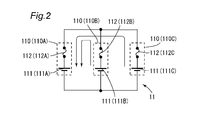
- FIG. 2 is an enlarged view of the battery subunit 11 in FIG.
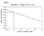
- FIG. 3 is a diagram illustrating the relationship between the current supplied by the secondary battery cell and the voltage detected by the voltage detection unit.
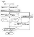
- FIG. 4 is a flowchart for explaining the operation of the first abnormality determination process in the first embodiment.
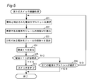
- FIG. 5 is a flowchart for explaining the operation of the first switch control process in the first embodiment.
- FIG. 6 is a circuit diagram showing a circuit configuration of the battery unit according to the second embodiment.
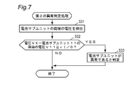
- FIG. 7 is a flowchart for explaining the operation of the second abnormality determination process in the second embodiment.
- FIG. 8 is a flowchart for explaining the operation of the second switch control process in the second embodiment.
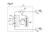
- FIG. 9 is a circuit diagram showing a circuit configuration of the battery unit according to the third embodiment.
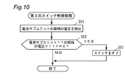
- FIG. 10 is a flowchart for explaining the operation of the third switch control process in the third
- FIG. 1 is a circuit diagram showing a circuit configuration of the battery unit 1 according to the first embodiment.
- the battery unit 1 includes battery subunits 11, 12 and 13, a switch 20, voltage detection units 311, 321 and 331, and a voltage monitoring circuit 30.
- Identification information ID11, ID12, and ID13 are given to battery subunits 11, 12, and 13, respectively.
- the identification information ID11, ID12, and ID13 are information for identifying the battery subunits 11, 12, and 13, respectively.
- the battery subunits 11, 12, and 13 are connected in series between the positive terminal 40 and the negative terminal 50.
- the battery subunit 11 includes three battery modules 110.
- the three battery modules 110 are connected in parallel between the switch 20 and the battery subunit 12.
- Each battery module 110 includes a secondary battery cell 111 and a fuse 112. Secondary battery cell 111 and fuse 112 are connected in series.
- the battery subunit 12 includes three battery modules 120.
- the three battery modules 120 are connected in parallel between the battery subunit 11 and the battery subunit 13.
- Each battery module 120 includes a secondary battery cell 121 and a fuse 122. Secondary battery cell 121 and fuse 122 are connected in series.
- the battery subunit 13 includes three battery modules 130.
- the three battery modules 130 are connected in parallel between the battery subunit 12 and the negative terminal 50.
- Each battery module 130 includes a secondary battery cell 131 and a fuse 132. Secondary battery cell 131 and fuse 132 are connected in series.
- Each of the secondary battery cells 111, 121, and 131 is a chargeable / dischargeable cell, and includes, for example, a lithium ion secondary battery, a nickel hydride secondary battery, or the like.
- Each of the fuses 112, 122, and 132 is blown when a current exceeding the rating flows.
- the switch 20 is connected between the positive terminal of the battery subunit 11 and the load. Specifically, it is connected between the positive terminal of the battery subunit 11 and the positive terminal 40.
- the switch 20 is composed of a field effect transistor, for example.
- the voltage detector 311 is connected to both ends of the battery subunit 11.
- the voltage detection unit 321 is connected to both ends of the battery subunit 12.
- the voltage detection unit 331 is connected to both ends of the battery subunit 13.
- the voltage detector 311 detects the voltage V11 at both ends of the battery subunit 11 and outputs the detected voltage V11 to the voltage monitoring circuit 30.
- the voltage detector 321 detects the voltage V12 at both ends of the battery subunit 12 and outputs the detected voltage V12 to the voltage monitoring circuit 30.
- the voltage detector 331 detects the voltage V13 across the battery subunit 13 and outputs the detected voltage V13 to the voltage monitoring circuit 30.
- the voltage monitoring circuit 30 monitors the voltages V11, V12, and V13 across the battery subunits 11, 12, and 13 instead of monitoring the voltages across the secondary battery cells 111, 121, and 131.
- the rated currents of the fuses 112, 122, 132 are set larger than the allowable current of the secondary battery cells 111, 121, 131.
- the voltage drop of the fuses 112, 122, 132 is several. It is about mV.
- the fuses 112, 122, 132 are larger than the allowable current, and when a current greater than the rated current flows, the resistance suddenly increases and blows. Therefore, when the secondary battery cell is normal, the voltage drop in the fuses 112, 122, and 132 is about several mV, and the voltage monitoring circuit 30 uses the voltages V11 and V12 across the battery subunits 11, 12, and 13, respectively. , V13 can be monitored to monitor the secondary battery cells 111, 121, 131 themselves.
- the voltage monitoring circuit 30 holds a resistance value r of an internal resistance (not shown) in each of the secondary battery cells 111, 121, 131. In addition, the voltage monitoring circuit 30 holds the current value of the allowable current of each secondary battery cell 111, 121, 131.
- the voltage monitoring circuit 30 monitors the voltages V11, V12, and V13 at both ends of the plurality of battery subunits 11, 12, and 13. Specifically, the voltage monitoring circuit 30 receives the voltages V11, V12, and V13 from the voltage detection units 311, 321, and 331, respectively.
- the voltage monitoring circuit 30 determines which of the battery subunits 11, 12, 13 is abnormal. Specifically, when determining whether or not the battery subunit 11 is abnormal, the voltage monitoring circuit 30 calculates the average voltage Vave of the voltages V12 and V13 received from the voltage detection units 321 and 331. And the voltage monitoring circuit 30 determines whether the battery subunit 11 is abnormal by the method mentioned later. When the voltage monitoring circuit 30 determines that the battery subunit 11 is abnormal, the voltage monitoring circuit 30 stores the identification information ID11 of the battery subunit 11.
- the voltage monitoring circuit 30 determines whether or not each of the battery subunits 12 and 13 is abnormal.
- the voltage monitoring circuit 30 determines whether or not to turn off the switch 20. Specifically, when it is determined that the battery subunit 11 is abnormal, the voltage monitoring circuit 30 determines that the battery that is normal among the three battery modules 110 included in the battery subunit 11 by a method described later. The number N of modules 110 is calculated. The voltage monitoring circuit 30 divides the current flowing through the battery subunit 11 by the calculated number (the number of normal battery modules 110) N, thereby obtaining the current I1 flowing through one normal secondary battery cell 111. calculate. The voltage monitoring circuit 30 turns off the switch 20 when the current I1 exceeds the allowable current of the secondary battery cell 111 included in the battery module 110 in which the current I1 is normal. Thereby, the battery unit 1 stops supply of electric power to the load.
- the voltage monitoring circuit 30 determines whether or not to turn off the switch 20 when it is determined that the battery subunits 12 and 13 are abnormal.
- FIG. 2 is an enlarged view of the battery subunit 11 in FIG.
- the fuse connected in series to the secondary battery cell in which the abnormality has occurred is blown out.
- the fuse connected in series to the secondary battery cell in which the abnormality has occurred is blown out in the same manner.
- FIG. 3 is a diagram showing the relationship between the current supplied by each secondary battery cell 111 and the voltage V11 detected by the voltage detector 311. As the current supplied by one secondary battery cell 111 increases, the voltage V11 across the battery subunit 11 decreases. This means that in the battery subunit 11, if the number of abnormal battery modules 110 increases, the voltage V11 across the battery subunit 11 decreases. Therefore, the voltage monitoring circuit 30 can determine whether or not the battery subunit 11 is abnormal by monitoring the voltage V11 across the battery subunit 11.
- the abnormality determination of the battery subunit 11 is executed by the following method.
- the difference between the average voltage Vave of the voltages V12 and V13 at both ends of the battery subunits 12 and 13 not subject to abnormality determination and the voltage V11 at both ends of the battery subunit 11 subject to abnormality determination is equal to or greater than a threshold value.
- the threshold is set to rI / 6. The reason why the threshold is set to rI / 6 will be described below.
- the voltage monitoring circuit 30 receives voltages V11A to V11C of different values.
- the voltage monitoring circuit 30 can determine that one battery module 110 is abnormal.
- the voltage monitoring circuit 30 Can determine that the two battery modules 110 are abnormal.
- the voltage monitoring circuit 30 determines that one or more battery modules 110 are abnormal when the difference between the average voltage Vave and the voltage V11 at both ends of the battery subunit 11 that is the target of abnormality determination is greater than or equal to rI / 6. Can be determined. Therefore, the voltage monitoring circuit 30 can determine whether or not the battery subunit 11 is abnormal by monitoring the voltage V11 across the battery subunit 11.
- the operation of the battery unit 1 in the first embodiment includes a first abnormality determination process shown in FIG. 4 and a first switch control process shown in FIG. First, the first abnormality determination process will be described with reference to FIG. The first abnormality determination process is executed at regular time intervals.
- step S11 the voltages V11, V12, V13 across the battery subunits 11, 12, 13 are detected (step S11). Specifically, the voltage detectors 311, 321, and 331 detect the voltages V11, V12, and V13 at both ends of the battery subunits 11, 12, and 13, respectively, and the detected voltages V11, V12, and V13 are voltage monitoring circuits. Output to 30.
- a battery subunit that is subject to abnormality determination is determined (step S12). Specifically, the voltage monitoring circuit 30 determines any one of the battery subunits 11, 12, and 13 as a battery subunit that is subject to abnormality determination. For example, the voltage monitoring circuit 30 determines the battery subunit 11 as a battery subunit that is a target of abnormality determination.
- step S12 the average voltage Vave of the battery subunits that are not subject to abnormality determination is calculated (step S13). Specifically, the voltage monitoring circuit 30 calculates the average voltage Vave by calculating the average of the voltages V12 and V13 at both ends of the battery subunits 12 and 13 that are not subjected to abnormality determination in the process of step S12. To do.
- the voltage monitoring circuit 30 determines whether or not the difference between the average voltage Vave and the voltage V11 at both ends of the battery subunit 11 that is the object of abnormality determination is greater than or equal to rI / 6 (step S13). S14). Thereby, the voltage monitoring circuit 30 can determine whether or not the battery subunit 11 is abnormal.
- step S14 When the difference between the average voltage Vave and the voltage V11 is equal to or greater than rI / 6 (YES in step S14), the voltage monitoring circuit 30 determines that the battery subunit 11 is abnormal, and the battery sub that is the target of abnormality determination The identification information ID11 of the unit 11 is stored (step S15). Thereafter, the process proceeds to step S16.
- step S14 If the difference between the average voltage Vave and the voltage V11 is not rI / 6 or more (NO in step S14), it is determined that the battery subunit 11 is normal, and the process proceeds to step S16.
- step S15 After the process of step S15 or when it is determined NO in the process of step S14, it is determined whether or not all the battery subunits 11, 12, and 13 have been subjected to the first abnormality determination (step S16). .
- the voltage monitoring circuit 30 determines the next determination target (step S17). Specifically, the voltage monitoring circuit 30 determines the next determination target by selecting any one battery subunit from battery subunits other than the battery subunit that has already been determined whether or not it is abnormal. .
- step S16 the above-described step S13 is performed until it is determined that all the battery subunits 11, 12, and 13 have been subjected to the first abnormality determination.
- Step S17 is repeatedly executed.
- step S16 If it is determined in step S16 that all the battery subunits 11, 12, and 13 have been subjected to the first abnormality determination (YES in step S16), the first abnormality determination process ends.
- the voltage monitoring circuit 30 is based on the voltages V11, V12, V13 at both ends of each battery subunit 11, 12, 13, and the battery subunits 11, 12, 13 It can be determined whether or not is abnormal.
- the first switch control process is periodically executed when the voltage monitoring circuit 30 stores the identification information.
- the battery subunit determined to be abnormal is selected (step S21). Specifically, the voltage monitoring circuit 30 selects the battery subunit corresponding to the identification information stored in step S15. In this example, it is assumed that the battery subunit 11 is selected.
- step S21 the number M of battery modules 110 that are abnormal in the selected battery subunit 11 is calculated (step S22). Specifically, the voltage monitoring circuit 30 calculates a difference Vave ⁇ V11 between the average voltage Vave and the voltage V11 at both ends of the battery subunit 11 selected in step S21. Then, the voltage monitoring circuit 30 calculates the number M of abnormal battery modules 110 based on the difference Vave ⁇ V11 between the average voltage Vave and the voltage V11 across the battery subunit 11.
- the voltage monitoring circuit 30 sets the number M of abnormal battery modules 110 to 2.
- step S23 the number N of normal battery modules 110 among the battery modules 110 included in the battery subunit 11 is determined (step S23). Specifically, the voltage monitoring circuit 30 calculates the difference between the total number of battery modules 110 included in the battery subunit 11 and the number M calculated in step S22, so that the battery included in the battery subunit 11 The number N of normal battery modules 110 among the modules 110 is calculated.
- step S24 the current I1 is calculated (step S24). Specifically, the voltage monitoring circuit 30 calculates the current I1 flowing through one normal battery module 110 by dividing the current flowing through the battery subunit 11 by the number N of normal battery modules 110. .
- step S24 the voltage monitoring circuit 30 determines whether or not the current I1 exceeds the allowable current of the secondary battery cell 111 (step S25).
- step S26 If the current I1 does not exceed the allowable current of the secondary battery cell 111 (NO in step S25), it is determined whether or not all battery subunits storing identification information have been selected (step S26).
- step S26 If not all battery subunits in which the identification information is stored are selected (NO in step S26), the process returns to step S21, and the battery subunit determined to be abnormal is selected. Specifically, the voltage monitoring circuit 30 selects a battery subunit that has not yet been selected among all the battery subunits in which the identification information is stored.
- step S26 If all the battery subunits in which the identification information is stored have been selected (YES in step S26), the first switch control process ends with the switch 20 turned on.
- step S25 When the current I1 exceeds the allowable current of the secondary battery cell 111 (YES in step S25), the voltage monitoring circuit 30 turns off the switch 20 (step S26). Thus, the battery unit 1 stops power supply to the load.
- step S26 the first switch control process ends.
- the battery subunit 11 Even if the battery subunit 11 is abnormal by executing the first switch control process described above, if the current flowing through the secondary battery cell 111 is within the allowable current range, the voltage monitoring circuit 30 The switch 20 is not turned off. That is, the battery unit 1 can continue to supply power to the load.
- the battery unit 1 includes battery modules 110, 120, and 130 in which battery subunits 11, 12, and 13 are connected in series with secondary battery cells 111, 121, and 131 and fuses 112, 122, and 132.
- the voltage monitoring circuit 30 monitors the voltages V11, V12, and V13 across the battery subunits 11, 12, and 13. When the current within the range of the rated current flows in the fuses 112, 122, 132, the voltage drop in the fuses 112, 122, 132 is about several mV. Therefore, by monitoring the voltages V11, V12, V13 across the battery subunits 11, 12, 13, it is possible to determine whether the secondary battery cells 111, 121, 131 themselves are abnormal. In addition, the battery unit 1 in the first embodiment detects an abnormality in the secondary battery cells 111, 121, 131 with the same accuracy as monitoring the voltage across the secondary battery cells 111, 121, 131. be able to.
- the voltage monitoring circuit 30 can determine the abnormality of the battery subunits 11, 12, 13 based on the monitored voltages V11, V12, V13.
- the battery unit 1 according to the first embodiment includes the battery subunits 11, 12, 13 in which the voltage monitoring circuit 30 connects the secondary battery cells 111, 121, 131 and the fuses 112, 122, 132 in series.
- the voltages V11, V12, and V13 at both ends are monitored. Therefore, the battery unit 1 according to the first embodiment can reduce the number of voltage detection units as compared with the case where the voltages at both ends of each of the secondary battery cells 111, 121, 131 are monitored. Can be simple.
- the battery modules 110, 120, and 130 include one secondary battery cell 111, 121, and 131.
- the present invention is not limited to this.
- the battery modules 110, 120, and 130 may include a plurality of secondary battery cells 111, 121, and 131 connected in series.
- the battery subunits 11, 12, and 13 include the same number of battery modules 110, 120, and 130, respectively, but the present invention is not limited to this.
- the number of battery modules may be changed for each battery subunit.
- step S14 it is determined whether or not the difference between the average voltage Vave and the voltage of the battery subunit that is the target of abnormality determination is greater than or equal to rI / 6. It is not limited to.
- the voltage monitoring circuit 30 holds the voltage across the battery subunits 11, 12, and 13 when the battery subunits 11, 12, and 13 are normal based on empirical rules, and the average voltage Vave in step S14. Instead of the voltage, the voltage across the battery subunits 11, 12, 13 when the battery subunits 11, 12, 13 are normal may be used.
- the switch 20 is connected between the positive terminal of the battery subunit 11 and the load.
- the switch 20 may be connected between the negative terminal of the battery subunit 13 and the load.
- FIG. 6 is a circuit diagram showing a circuit configuration of the battery unit 1X according to the second embodiment.
- the battery unit 1X according to the second embodiment is obtained by replacing the voltage monitoring circuit 30 of the battery unit 1 shown in FIG. 1 with the voltage monitoring circuit 30X and omitting the battery subunits 12 and 13 and the voltage detection units 321 and 331.
- the others are the same as those of the battery unit 1. That is, the battery unit 1 in the first embodiment includes the battery subunits 11, 12, and 13, whereas the battery unit 1 ⁇ / b> X in the second embodiment includes the battery subunit 11.
- the voltage monitoring circuit 30X holds the voltage VX across the battery subunit 11 when the battery subunit 11 is normal according to a rule of thumb.
- the other configuration of the voltage monitoring circuit 30X is the same as that of the voltage monitoring circuit 30 in the first embodiment.
- the voltage detection circuit 30X monitors the voltage V11 across the battery subunit 11. Specifically, the voltage monitoring circuit 30X receives the voltage V11 from the voltage detection unit 311.
- the voltage monitoring circuit 30X determines whether or not the battery subunit 11 is abnormal by a method described later. When it is determined that the battery subunit 11 is abnormal, the voltage monitoring circuit 30X further determines whether or not to turn off the switch 20. Specifically, the number N of normal battery modules 110 among the three battery modules 110 included in the battery subunit 11 is obtained by executing the same processing as the processing in steps S22 to S23 in FIG. calculate. The voltage monitoring circuit 30X calculates the supply current I2 that the battery unit 1X can supply to the load by calculating the product of the number N and the allowable current of one secondary battery cell 111. The voltage monitoring circuit 30X turns off the switch 20 when the supply current I2 becomes smaller than the current to be supplied to the load. Thereby, the battery unit 1X stops the supply of electric power to the load.
- the second abnormality determination process will be described with reference to FIG.
- the second abnormality determination process is executed at regular time intervals.
- the voltage V11 across the battery subunit 11 is detected (step S31). Specifically, the voltage detection unit 311 detects the voltage V11 and outputs the detected voltage V11 to the voltage monitoring circuit 30X.
- the voltage monitoring circuit 30X determines that the difference between the voltage VX across the battery subunit 11 when the battery subunit 11 is normal and the voltage V11 received from the voltage detector 311 is greater than or equal to rI / 6. It is determined whether or not (step S32). In this example, the threshold is set to rI / 6 for the same reason as the process in step S14 of the first abnormality determination process (FIG. 3).
- step S32 When the difference between voltage VX and voltage V11 received from voltage detector 311 is rI / 6 or more (YES in step S32), voltage monitoring circuit 30X determines that battery subunit 11 is abnormal (step S33). Thereby, the second abnormality determination process ends.
- the voltage monitoring circuit 30X can determine whether or not the battery subunit 11 is abnormal based on the voltage V11 across the battery subunit 11. .
- the second switch control process is executed when the voltage monitoring circuit 30X determines that the battery subunit 11 is abnormal.
- the number M of abnormal battery modules 110 is calculated (step S41). Specifically, the voltage monitoring circuit 30X sets the difference VX ⁇ V11 between the voltage VX and the voltage V11 at both ends of the battery subunit 11 in the same manner as the process in step S22 of the first switch control process (FIG. 4). Based on this, the number M of abnormal battery modules 110 is calculated.
- step S42 the number N of normal battery modules 110 among the battery modules 110 included in the battery subunit 11 is determined (step S42). Specifically, the voltage monitoring circuit 30X performs the normal operation of the battery module 110 that is normal among the battery modules 110 included in the battery subunit 11 in the same manner as the process in step S23 of the first switch control process (FIG. 4). The number N is calculated.
- the supply current I2 is calculated (step S43). Specifically, the voltage monitoring circuit 30X calculates the supply current I2 by calculating the product of the number N of normal battery modules 110 and the current value of the allowable current of one secondary battery cell 111. . That is, the supply current I2 is a current that the battery unit 1 can supply to the load.
- step S43 it is determined whether or not the supply current I2 is smaller than the current to be supplied to the load (step S44).
- step S44 When the supply current I2 is smaller than the current to be supplied to the load (YES in step S44), the switch is turned off (step S45). Thereby, the battery unit 1X stops the electric power supply with respect to load.
- step S45 the second switch control process ends.
- step S44 If the supply current I2 is not smaller than the current to be supplied to the load (NO in step S44), the second switch control process ends with the switch 20 kept on.
- the battery subunit 11 can supply the current to be supplied to the load even if the battery subunit 11 is abnormal by executing the second switch control process described above, voltage monitoring is performed.
- the circuit 30X does not turn off the switch 20. That is, the battery unit 1X can continue to supply power to the load.
- the battery module 110 contains the one secondary battery cell 111, it is not limited to this.
- the battery module 110 may connect a plurality of secondary battery cells 111 in series.
- the switch 20 is connected between the positive terminal of the battery subunit 11 and the load.
- the switch 20 may be connected between the negative terminal of the battery subunit 11 and the load.
- FIG. 9 is a circuit diagram showing a circuit configuration of a battery unit 1Y according to the third embodiment.
- the battery unit 1Y changes the battery subunit 11 of the battery unit 1 shown in FIG. 1 to the battery subunit 11Y, changes the voltage monitoring circuit 30 to the voltage monitoring circuit 30Y, and sets the voltage detection unit 311 to the voltage.
- the detection unit 321Y the battery subunits 12 and 13 and the voltage detection units 321 and 331 are omitted, and the rest is the same as the battery unit 1.
- the battery subunit 11Y includes one battery module 110 in FIG.
- the battery subunit 11Y is connected between the plus terminal 40 and the minus terminal 50.
- the voltage detector 311Y is connected to both ends of the battery subunit 11Y.
- the voltage detector 311Y detects the voltage V11Y across the battery subunit 11Y and outputs the detected voltage V11Y to the voltage monitoring circuit 30Y.
- the voltage monitoring circuit 30Y monitors the voltage V11Y across the battery subunit 11Y. Specifically, the voltage monitoring circuit 30Y receives the voltage V11Y from the voltage detection unit 311Y.
- the voltage monitoring circuit 30 determines that the battery subunit 11Y is abnormal.
- the voltage monitoring circuit 30Y determines that the battery subunit 11Y is abnormal, the voltage monitoring circuit 30Y turns off the switch 20. Thereby, battery unit 1Y stops supply of electric power to a load.
- the third switch control process is executed at regular time intervals.
- the voltage V11Y across the battery subunit 11Y is detected (step S51). Specifically, the voltage detector 311Y detects the voltage V11Y, and outputs the detected voltage V11Y to the voltage monitoring circuit 30Y.
- step S52 the voltage monitoring circuit 30Y determines whether or not the voltage V11Y received from the voltage detection unit 311Y is 0 (step S52).
- step S52 When the voltage V11Y received from the voltage detector 311Y is 0 (YES in step S52), the voltage monitoring circuit 30Y determines that the fuse 112 is blown, and turns off the switch 20 (step S53). Thereby, battery unit 1Y stops supply of electric power to a load.
- step S53 the third switch control determination process ends.
- step S52 When the voltage V11Y received from the voltage detector 311Y is not 0 (NO in step S52), the voltage monitoring circuit 30Y determines that the fuse 112 is not blown, and the third switch control process ends. .
- the voltage monitoring circuit 30Y can determine whether or not the battery subunit 11Y is abnormal based on the voltage V11Y across the battery subunit 11Y. .
- the battery module 110 contains the one secondary battery cell 111, it is not limited to this.
- the battery module 110 may connect a plurality of secondary battery cells 111 in series.
- the switch 20 is connected between the positive terminal of the battery subunit 11Y and the load.
- the switch 20 may be connected between the negative terminal of the battery subunit 11Y and the load.
- step S53 when the voltage V11Y received from the voltage detection unit 311Y is 0, the voltage monitoring circuit 30Y has been described as turning off the switch 20 (step S53), but the present invention is not limited to this.
- the process of step S53 of the third switch control process may be omitted. This is because the battery unit 1Y cannot supply power to the load when the fuse 112 is blown.
- This invention is applied to a battery unit.
Landscapes
- Chemical & Material Sciences (AREA)
- Chemical Kinetics & Catalysis (AREA)
- Electrochemistry (AREA)
- General Chemical & Material Sciences (AREA)
- Engineering & Computer Science (AREA)
- Manufacturing & Machinery (AREA)
- Power Engineering (AREA)
- Secondary Cells (AREA)
- Charge And Discharge Circuits For Batteries Or The Like (AREA)
Abstract
Description
図1~5を参照して、第1の実施の形態における電池ユニット1を説明する。図1は、第1の実施の形態による電池ユニット1の回路構成を示す回路図である。
第1の実施の形態による電池ユニット1は、電池サブユニット11,12,13が二次電池セル111,121,131とヒューズ112,122,132とを直列に接続した電池モジュール110,120,130を含み、電圧監視回路30が電池サブユニット11,12,13の両端の電圧V11,V12,V13を監視する。ヒューズ112,122,132内に定格電流の範囲内の電流が流れている場合、ヒューズ112,122,132における電圧降下は、数mV程度である。したがって、電池サブユニット11,12,13の両端の電圧V11,V12,V13を監視することにより、二次電池セル111,121,131自体が異常であるか否かを判定することができる。また、第1の実施の形態における電池ユニット1は、二次電池セル111,121,131の両端の電圧を監視するのと同等の精度で二次電池セル111,121,131の異常を検出することができる。
第1の実施の形態では、電池モジュール110,120,130は、1個の二次電池セル111,121,131を含んでいるが、これに限定されない。例えば、電池モジュール110,120,130は、直列に接続された複数の二次電池セル111,121,131を含んでいてもよい。
次に、図6~8を参照して、第2の実施の形態における電池ユニット1Xを説明する。図6は、第2の実施の形態による電池ユニット1Xの回路構成を示す回路図である。
第2の実施の形態では、電池モジュール110は、1個の二次電池セル111を含んでいるが、これに限定されない。例えば、電池モジュール110が、複数の二次電池セル111を直列に接続してもよい。
次に、図9及び図10を参照して、第3の実施の形態における電池ユニット1Yを説明する。図9は、第3の実施の形態による電池ユニット1Yの回路構成を示す回路図である。
第3の実施の形態では、電池モジュール110は、1個の二次電池セル111を含んでいるが、これに限定されない。例えば、電池モジュール110が、複数の二次電池セル111を直列に接続してもよい。
Claims (5)
- 二次電池セルとヒューズとを直列に接続した電池モジュールを含む電池サブユニットと、
前記電池サブユニットの両端の電圧を監視する電圧監視回路と、
前記電池サブユニットと負荷との間に接続されたスイッチとを備え、
前記電池サブユニットは、1又は並列に接続された複数の前記電池モジュールを含み、
前記電圧監視回路は、前記電池サブユニットが1個の前記電池モジュールを含む場合、前記電池モジュール内の前記ヒューズが溶断されたことを確認したとき、前記スイッチをオフし、前記電池サブユニットが複数の前記電池モジュールを含む場合、前記電圧に基づいて、前記電池サブユニットが、負荷に対して供給すべき電流を流すことができないとき、前記スイッチをオフする、電池ユニット。 - 二次電池セルとヒューズとを直列に接続した電池モジュールを含む電池サブユニットと、
前記電池サブユニットの両端の電圧を監視する電圧監視回路と、
前記電池サブユニットと負荷との間に接続されたスイッチとを備え、
前記電池サブユニットは、1又は並列に接続された複数の前記電池モジュールを含み、
前記電池サブユニットが直列に複数個接続され、
前記電圧監視回路は、前記複数の電池サブユニットの各々の両端の電圧を監視するとともに、前記複数の電池サブユニットの各々が1個の前記電池モジュールを含む場合、前記電池モジュール内の前記ヒューズが溶断されたことを確認したとき、前記スイッチをオフし、前記複数の電池サブユニットの各々が複数の前記電池モジュールを含む場合、前記電圧に基づいて、前記複数の電池サブユニットのうちいずれかが、負荷に対して供給すべき電流を流すことができないとき、前記スイッチをオフする、電池ユニット。 - 二次電池セルとヒューズとを直列に接続した電池モジュールを含む電池サブユニットと、
前記電池サブユニットの両端の電圧を監視する電圧監視回路と、
前記電池サブユニットと負荷との間に接続されたスイッチとを備え、
前記電池サブユニットは、1又は並列に接続された複数の前記電池モジュールを含み、
前記電圧監視回路は、前記電池サブユニットが1個の前記電池モジュールを含む場合、前記電池モジュール内の前記ヒューズが溶断されたことを確認したとき、前記スイッチをオフし、前記電池サブユニットが複数の前記電池モジュールを含む場合、前記電圧に基づいて、正常である1個の電池モジュールに流れる電流が前記二次電池セルの許容電流を超えたとき、前記スイッチをオフする、電池ユニット。 - 二次電池セルとヒューズとを直列に接続した電池モジュールを含む電池サブユニットと、
前記電池サブユニットの両端の電圧を監視する電圧監視回路と、
前記電池サブユニットと負荷との間に接続されたスイッチとを備え、
前記電池サブユニットは、1又は並列に接続された複数の前記電池モジュールを含み、
前記電池サブユニットが直列に複数個接続され、
前記電圧監視回路は、前記複数の電池サブユニットの各々の両端の電圧を監視するとともに、前記複数の電池サブユニットの各々が1個の前記電池モジュールを含む場合、前記電池モジュール内の前記ヒューズが溶断されたことを確認したとき、前記スイッチをオフし、前記複数の電池サブユニットの各々が複数の前記電池モジュールを含む場合、前記電圧に基づいて、正常である1個の電池モジュールに流れる電流が前記二次電池セルの許容電流を超えたとき、前記スイッチをオフする、電池ユニット。 - 請求項3または4に記載の電池ユニットであって、
前記電圧監視回路は、前記複数の電池サブユニットの各々が前記複数の電池モジュールを含む場合、前記電圧に基づいて正常である電池モジュールの個数を算出し、負荷に対して供給すべき電流を前記個数で割ることにより前記電流を算出する、電池ユニット。
Priority Applications (3)
| Application Number | Priority Date | Filing Date | Title |
|---|---|---|---|
| KR1020137003872A KR20130141440A (ko) | 2011-01-28 | 2012-01-16 | 전지 유닛 |
| CN2012800025351A CN103262384A (zh) | 2011-01-28 | 2012-01-16 | 电池单元 |
| US13/818,125 US20130149572A1 (en) | 2011-01-28 | 2012-01-16 | Battery unit |
Applications Claiming Priority (2)
| Application Number | Priority Date | Filing Date | Title |
|---|---|---|---|
| JP2011016460A JP5670212B2 (ja) | 2011-01-28 | 2011-01-28 | 電池ユニット |
| JP2011-016460 | 2011-01-28 |
Publications (1)
| Publication Number | Publication Date |
|---|---|
| WO2012102115A1 true WO2012102115A1 (ja) | 2012-08-02 |
Family
ID=46580687
Family Applications (1)
| Application Number | Title | Priority Date | Filing Date |
|---|---|---|---|
| PCT/JP2012/050736 Ceased WO2012102115A1 (ja) | 2011-01-28 | 2012-01-16 | 電池ユニット |
Country Status (5)
| Country | Link |
|---|---|
| US (1) | US20130149572A1 (ja) |
| JP (1) | JP5670212B2 (ja) |
| KR (1) | KR20130141440A (ja) |
| CN (1) | CN103262384A (ja) |
| WO (1) | WO2012102115A1 (ja) |
Cited By (2)
| Publication number | Priority date | Publication date | Assignee | Title |
|---|---|---|---|---|
| CN103682234A (zh) * | 2012-08-30 | 2014-03-26 | 电能有限公司 | 带独立切断保护的电池组 |
| WO2014115513A1 (ja) * | 2013-01-22 | 2014-07-31 | 三洋電機株式会社 | 電池モジュールの故障推定システム |
Families Citing this family (24)
| Publication number | Priority date | Publication date | Assignee | Title |
|---|---|---|---|---|
| DE102012213422A1 (de) * | 2012-07-31 | 2014-02-06 | Robert Bosch Gmbh | Batteriemanagementsystem, Kraftfahrzeug und Batteriesystem |
| US9991723B2 (en) | 2012-09-17 | 2018-06-05 | The Boeing Company | Virtual cell method for battery management |
| JP5870907B2 (ja) * | 2012-12-07 | 2016-03-01 | トヨタ自動車株式会社 | 蓄電システム |
| CN104079017B (zh) * | 2013-03-28 | 2016-08-03 | 比亚迪股份有限公司 | 一种电池管理装置、电源系统及电池均衡的方法 |
| CN104184178A (zh) * | 2013-05-24 | 2014-12-03 | 中国北车股份有限公司 | 列车再生电能吸收装置和系统 |
| CN104184200A (zh) * | 2013-05-24 | 2014-12-03 | 台达电子工业股份有限公司 | 电源适配器、电源适配器的控制方法及笔记本 |
| KR20150067832A (ko) * | 2013-12-10 | 2015-06-19 | 현대자동차주식회사 | 배터리 모듈화 구조에서의 모듈 정보 갱신 방법 |
| US9726731B2 (en) * | 2013-12-31 | 2017-08-08 | Chervon (Hk) Limited | Battery pack, method for detecting battery pack, charging assembly and electric tool |
| CN104753129B (zh) * | 2013-12-31 | 2018-01-19 | 南京德朔实业有限公司 | 电池包、充电组合、电动工具以及断线检测方法 |
| WO2015107630A1 (ja) * | 2014-01-15 | 2015-07-23 | デクセリアルズ株式会社 | 保護回路、バッテリユニット |
| CN104079071B (zh) * | 2014-07-10 | 2017-07-04 | 国家电网公司 | 一种电力线载波用电参数接收控制装置及方法 |
| CN104184187B (zh) * | 2014-08-12 | 2016-09-14 | 安徽安凯汽车股份有限公司 | 一种电动汽车动力电池充放电均衡系统及方法 |
| CN104158249B (zh) * | 2014-08-13 | 2017-01-18 | 清华大学 | 一种共母线回馈储能型港机供电装备 |
| CN104184191B (zh) * | 2014-08-21 | 2016-11-02 | 广州益维电动汽车有限公司 | 一种电动汽车整车控制装置及其控制方法 |
| CN104158266B (zh) * | 2014-08-29 | 2016-09-28 | 普天新能源车辆技术有限公司 | 一种车载电池管理系统 |
| CN104158264A (zh) * | 2014-09-01 | 2014-11-19 | 苏州凯丰电子电器有限公司 | 一种太阳能充电器 |
| JP6279442B2 (ja) * | 2014-10-03 | 2018-02-14 | 矢崎総業株式会社 | 故障検出システム |
| CN104578331A (zh) * | 2015-03-02 | 2015-04-29 | 张琦 | 一种带开关的充电器 |
| CN105405281A (zh) * | 2015-11-25 | 2016-03-16 | 国网辽宁省电力有限公司锦州供电公司 | 一种电力智能表载波通讯故障检测方法 |
| KR102259215B1 (ko) * | 2016-09-01 | 2021-05-31 | 삼성에스디아이 주식회사 | 배터리 보호 장치 |
| US11462777B2 (en) * | 2017-10-04 | 2022-10-04 | Envision Aesc Japan Ltd. | Battery pack inspection method and inspection device for anomaly detection via voltage comparison over time |
| JP7316967B2 (ja) * | 2020-03-25 | 2023-07-28 | 日立Astemo株式会社 | 電圧検出装置 |
| KR102848533B1 (ko) * | 2021-06-25 | 2025-08-20 | 주식회사 엘지에너지솔루션 | 배터리 상태 검출 장치 및 배터리 보호 장치 |
| FR3164845A1 (fr) * | 2024-07-16 | 2026-01-23 | Saft | Système de protection d’une batterie et batterie |
Citations (3)
| Publication number | Priority date | Publication date | Assignee | Title |
|---|---|---|---|---|
| JP2000357540A (ja) * | 1999-06-14 | 2000-12-26 | Matsushita Electric Ind Co Ltd | 二次電池の保護回路 |
| JP2004103483A (ja) * | 2002-09-12 | 2004-04-02 | Solectron Japan Kk | バッテリパック |
| WO2010008026A2 (ja) * | 2008-07-16 | 2010-01-21 | Necトーキン株式会社 | 電池パック |
Family Cites Families (7)
| Publication number | Priority date | Publication date | Assignee | Title |
|---|---|---|---|---|
| JP2002369372A (ja) * | 2001-06-04 | 2002-12-20 | Nissan Motor Co Ltd | 組電池 |
| JP5092321B2 (ja) * | 2006-09-04 | 2012-12-05 | ソニー株式会社 | 電池パックおよび検出方法 |
| JP4840154B2 (ja) * | 2007-01-23 | 2011-12-21 | パナソニック株式会社 | 電源機器 |
| JP5319224B2 (ja) * | 2008-09-25 | 2013-10-16 | 株式会社東芝 | 組電池システム |
| JP2010088202A (ja) * | 2008-09-30 | 2010-04-15 | Toshiba Corp | 電池ユニットおよびこれを用いた電池システム |
| JP5675045B2 (ja) * | 2008-11-26 | 2015-02-25 | 三洋電機株式会社 | バッテリシステム |
| CN102472802A (zh) * | 2010-03-26 | 2012-05-23 | 松下电器产业株式会社 | 充电状态检测电路、电池电源装置以及电池信息监视装置 |
-
2011
- 2011-01-28 JP JP2011016460A patent/JP5670212B2/ja active Active
-
2012
- 2012-01-16 WO PCT/JP2012/050736 patent/WO2012102115A1/ja not_active Ceased
- 2012-01-16 KR KR1020137003872A patent/KR20130141440A/ko not_active Withdrawn
- 2012-01-16 CN CN2012800025351A patent/CN103262384A/zh active Pending
- 2012-01-16 US US13/818,125 patent/US20130149572A1/en not_active Abandoned
Patent Citations (3)
| Publication number | Priority date | Publication date | Assignee | Title |
|---|---|---|---|---|
| JP2000357540A (ja) * | 1999-06-14 | 2000-12-26 | Matsushita Electric Ind Co Ltd | 二次電池の保護回路 |
| JP2004103483A (ja) * | 2002-09-12 | 2004-04-02 | Solectron Japan Kk | バッテリパック |
| WO2010008026A2 (ja) * | 2008-07-16 | 2010-01-21 | Necトーキン株式会社 | 電池パック |
Cited By (3)
| Publication number | Priority date | Publication date | Assignee | Title |
|---|---|---|---|---|
| CN103682234A (zh) * | 2012-08-30 | 2014-03-26 | 电能有限公司 | 带独立切断保护的电池组 |
| WO2014115513A1 (ja) * | 2013-01-22 | 2014-07-31 | 三洋電機株式会社 | 電池モジュールの故障推定システム |
| JPWO2014115513A1 (ja) * | 2013-01-22 | 2017-01-26 | 三洋電機株式会社 | 電池モジュールの故障推定システム |
Also Published As
| Publication number | Publication date |
|---|---|
| KR20130141440A (ko) | 2013-12-26 |
| JP2012157217A (ja) | 2012-08-16 |
| CN103262384A (zh) | 2013-08-21 |
| JP5670212B2 (ja) | 2015-02-18 |
| US20130149572A1 (en) | 2013-06-13 |
Similar Documents
| Publication | Publication Date | Title |
|---|---|---|
| JP5670212B2 (ja) | 電池ユニット | |
| JP5174421B2 (ja) | 電池パック、及び電池システム | |
| JP5554204B2 (ja) | 工具用バッテリ | |
| JP6056730B2 (ja) | 蓄電システム | |
| US9933489B2 (en) | Battery monitoring apparatus | |
| JP5910889B2 (ja) | 蓄電システム | |
| US9267998B2 (en) | Protective circuit for a rechargeable battery pack | |
| JP2009212020A (ja) | 蓄電装置 | |
| JP2009059504A (ja) | 電池パックおよび制御方法 | |
| GB2559793A (en) | Battery pack with reduced voltage variance | |
| CN103208785B (zh) | 用于蓄电池组的保护电路 | |
| JP6026225B2 (ja) | 蓄電システム | |
| WO2009107236A1 (ja) | パック電池の充電装置及びパック電池の品質判定装置 | |
| JP5361298B2 (ja) | 電池パック | |
| JP6774628B2 (ja) | 電池監視装置の保護回路、及び電池監視装置 | |
| JP4878573B2 (ja) | 電池保護回路、及び電池パック | |
| WO2013021956A1 (ja) | 充放電制御装置 | |
| JP5750739B2 (ja) | 二次電池の保護回路 | |
| JP2000340266A (ja) | 電池並列使用時の異常検出方法 | |
| JP4660497B2 (ja) | バッテリパックの監視保護装置 | |
| JP2012119249A (ja) | 電池パック及び電池モジュール | |
| JP5092321B2 (ja) | 電池パックおよび検出方法 | |
| JP5163624B2 (ja) | 電池監視装置 | |
| KR102947449B1 (ko) | 배터리 차단 장치, 배터리 장치 및 전력 차단 방지 방법 | |
| JP2009207332A (ja) | パック電池の充電装置及びパック電池の品質判定装置 |
Legal Events
| Date | Code | Title | Description |
|---|---|---|---|
| 121 | Ep: the epo has been informed by wipo that ep was designated in this application |
Ref document number: 12739456 Country of ref document: EP Kind code of ref document: A1 |
|
| ENP | Entry into the national phase |
Ref document number: 20137003872 Country of ref document: KR Kind code of ref document: A |
|
| WWE | Wipo information: entry into national phase |
Ref document number: 13818125 Country of ref document: US |
|
| NENP | Non-entry into the national phase |
Ref country code: DE |
|
| 122 | Ep: pct application non-entry in european phase |
Ref document number: 12739456 Country of ref document: EP Kind code of ref document: A1 |