WO2012096009A1 - 太陽電池モジュール用端子ボックス - Google Patents
太陽電池モジュール用端子ボックス Download PDFInfo
- Publication number
- WO2012096009A1 WO2012096009A1 PCT/JP2011/061992 JP2011061992W WO2012096009A1 WO 2012096009 A1 WO2012096009 A1 WO 2012096009A1 JP 2011061992 W JP2011061992 W JP 2011061992W WO 2012096009 A1 WO2012096009 A1 WO 2012096009A1
- Authority
- WO
- WIPO (PCT)
- Prior art keywords
- base plate
- plate
- solar cell
- resin
- terminal box
- Prior art date
- Legal status (The legal status is an assumption and is not a legal conclusion. Google has not performed a legal analysis and makes no representation as to the accuracy of the status listed.)
- Ceased
Links
Images





Classifications
-
- H—ELECTRICITY
- H02—GENERATION; CONVERSION OR DISTRIBUTION OF ELECTRIC POWER
- H02S—GENERATION OF ELECTRIC POWER BY CONVERSION OF INFRARED RADIATION, VISIBLE LIGHT OR ULTRAVIOLET LIGHT, e.g. USING PHOTOVOLTAIC [PV] MODULES
- H02S40/00—Components or accessories in combination with PV modules, not provided for in groups H02S10/00 - H02S30/00
- H02S40/30—Electrical components
- H02S40/34—Electrical components comprising specially adapted electrical connection means to be structurally associated with the PV module, e.g. junction boxes
- H02S40/345—Electrical components comprising specially adapted electrical connection means to be structurally associated with the PV module, e.g. junction boxes with cooling means associated with the electrical connection means, e.g. cooling means associated with or applied to the junction box
-
- Y—GENERAL TAGGING OF NEW TECHNOLOGICAL DEVELOPMENTS; GENERAL TAGGING OF CROSS-SECTIONAL TECHNOLOGIES SPANNING OVER SEVERAL SECTIONS OF THE IPC; TECHNICAL SUBJECTS COVERED BY FORMER USPC CROSS-REFERENCE ART COLLECTIONS [XRACs] AND DIGESTS
- Y02—TECHNOLOGIES OR APPLICATIONS FOR MITIGATION OR ADAPTATION AGAINST CLIMATE CHANGE
- Y02E—REDUCTION OF GREENHOUSE GAS [GHG] EMISSIONS, RELATED TO ENERGY GENERATION, TRANSMISSION OR DISTRIBUTION
- Y02E10/00—Energy generation through renewable energy sources
- Y02E10/50—Photovoltaic [PV] energy
Definitions
- the present invention relates to a terminal box for a solar cell module.
- Patent Document 1 discloses a conventional solar cell module terminal box (hereinafter referred to as a terminal box). This has a bottom wall and a peripheral wall surrounding the bottom wall, and the bottom wall and the peripheral wall are integrally formed.
- a heat sink is mounted on the bottom wall, and a diode (rectifier) is mounted on the heat sink.
- a hole is formed through the diode, and a screw hole is formed in the heat sink.
- the diode is fixed to the heat sink.
- the diode generates heat, the heat is dissipated to the heat dissipation plate, and is further dissipated from the heat dissipation plate to the solar cell panel side via the bottom wall.
- the protrusion is made to project from the bottom plate, and the protrusion is inserted into the hole of the diode, and in that state, the tip portion of the protrusion protruding from the heat sink is resin crimped.
- the method of holding a diode was considered. However, in such a method, when the diode becomes high temperature, the heat damage may deform the tip end of the protrusion, and the holding power at the time of holding the diode may be reduced.
- the present invention has been completed based on the above-described circumstances, and it is an object of the present invention to provide a method other than screwing when fixing a rectifying device, and to improve the holding reliability of the rectifying device.
- the present invention relates to a terminal box for a solar cell module attached to a solar cell module, which is a flat plate made of resin and having a heat resistance lower than that of the base plate, and a frame shape surrounding the base plate. And an outer plate to which the base plate is attached and fixed, a heat sink supported by the base plate, a heat sink supported by the heat sink, and a protrusion capable of being inserted A rectifying element having a mounting hole, and a tip end portion of the protrusion, which penetrates the mounting hole to face the surface side of the rectifying element, and is deformed by resin caulking so that the rectifying element is made with the base plate And a resin caulking portion held between the two.
- the outer plate has lower heat resistance than the base plate, in other words, the base plate has higher heat resistance than the outer plate, and the projection is integrally formed on the base plate, the resin caulking portion may be deformed. Becomes lower. As a result, the reliability in holding the rectifying element is enhanced.
- the present invention can have the following configuration.
- the projection may penetrate the heat sink together with the mounting hole, and the resin caulking part may hold the heat sink between the rectifying element and the base plate. In this case, it is not necessary to separately provide a dedicated fixing means for fixing the heat sink, and the configuration is simplified.
- the protrusion includes a large diameter protrusion that is thicker than the other protrusions, and the large diameter protrusion penetrates the heat sink together with the mounting hole, and the resin is located at the tip of the large diameter protrusion
- the caulking portion may hold the heat sink together with the rectifying element and the base plate. With such a large diameter projection, it is possible to secure the strength necessary to hold both the rectifying element and the heat sink.
- a plurality of holes into which the protrusions can be inserted may be formed through the heat dissipation plate, and the holes may be arranged at intervals in the extending direction of the heat dissipation plate. In this case, the heat sink is positioned by the protrusions.
- the base plate may be made of at least one selected from PBT (polybutylene terephthalate) and PPS (polyphenylene sulfide). According to this, deformation of the resin caulking portion is reliably prevented.
- the outer plate may be made of at least one selected from PPO (polyphenylene oxide), PPE (polyphenylene ether), and PVC (polyvinyl chloride). According to this, it is excellent in weather resistance and hydrolysis resistance. In addition, the quality of the terminal box can be further enhanced by appropriately dividing and forming the base plate and the outer plate.
- the base plate may be mounted on the outer plate by sliding. According to this, the base plate is easily attached to the outer plate.
- An elastic locking piece is formed so as to protrude inward on the outer plate, a locking receiving portion is formed on the base plate, and the elastic engagement is formed as the base plate is mounted on the outer plate.
- a stop may resiliently lock the lock receiving portion. In this way, the base plate is easily fixed to the outer plate along with its sliding movement.
- a pressing piece is formed on the outer plate so as to protrude inward, and as the base plate is attached, the heat sink abuts on the pressing piece and the floating of the heat sink is restricted. Good. This prevents the base plate from being detached from the outer plate.
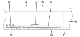
- FIG. 2 is a cross-sectional view taken along the line BB of FIG.
- FIG. 2 is a cross-sectional view taken along the line CC of FIG.
- It is the DD sectional view taken on the line of FIG.
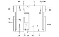
- It is a top view of a base plate. It is a top view of the base plate which supports a terminal board. It is a top view of an outer plate.
- the solar cell module terminal box (hereinafter referred to simply as the terminal box 10) according to the first embodiment includes the box body 20, a plurality of terminal plates 90, and one bypass diode (a heating element). ) And.
- the box body 20 is made of a synthetic resin and has a plate box shape as a whole, and includes a rectangular base plate 21 and an outer plate 22 surrounding the base plate 21.
- the base plate 21 constitutes a bottom wall of the box body 20, and the outer plate 22 constitutes a peripheral wall of the box body 20. Then, the base plate 21 is detachably slide-mounted and fixed to the outer plate 22.
- the outer plate 22 has a rectangular frame shape rising from the peripheral portion of the base plate 21 and, as shown in FIG. 9, includes a pair of left and right side walls 23 and front and rear front and rear walls 24, 25.
- the rear wall 25 is formed with a pair of left and right cable insertion portions 26.
- Each of the cable insertion portions 26 has a cylindrical shape that protrudes rearward through the rear wall 25, and the cables 70 on the plus side and the minus side are respectively inserted from the rear into the inside.
- a rubber tube 75 is fitted in the cable insertion portion 26. The tube 75 is in close contact with the cable insertion portion 26 and the cable 70, and thereby has a role of sealing both of them in a fluid tight manner.
- a closing plate 27 is formed at the rear end of the box body 20.
- the closing plate 27 partially closes the inner space defined by the side walls 23 and the front and rear walls 24 and 25.
- the closing plate 27 is continuous with the inner surfaces of the rear wall 25 and the both side walls 23 and disposed substantially parallel to the base plate 21.
- a pair of left and right jig insertion holes 28 are formed through the closing plate 27.
- the core wire 71 is exposed at the end of the cable 70.
- Barrel pieces (described later) of the terminal plate 90 are connected to the core wire 71 by pressure bonding.
- the barrel piece is crimped to the core wire 71, the barrel piece is deformed by a jig composed of an anvil (lower mold) and a crimper (upper mold) not shown, and the barrel piece is wound around the core wire 71 in that state.
- the jig is inserted into the box body 20 through the jig insertion hole 28 of the closing plate 27.
- a plate-like elastic locking piece 29 is formed to project forward at a position slightly closer to one side than the widthwise center.
- a locking projection 30 is formed on the upper surface of the resilient locking piece 29 so as to project therefrom.
- the elastic locking piece 29 has a role of locking the base plate 21 mounted on the outer plate 22 and blocking the detachment of the base plate 21 from the outer plate 22.
- First and second slide receiving portions 31 and 32 which can slide on first and second slide portions 38 and 39 (described later) of the base plate 21 are formed on the inner surfaces of both side walls 23 so as to extend in the front-rear direction ing.
- the first slide receiving portion 31 extends forward from the front end portion of the closing plate 27 and is configured to drop by one step at the front end portion.
- the second slide receiving portion 32 extends straight forward from substantially the same longitudinal position as the front end of the first slide receiving portion 31 and is located one step higher than the first slide receiving portion 31.
- the second slide receiving portion 32 is shorter than the first slide receiving portion 31.
- a pressing piece 33 capable of pressing the terminal plate 90 from above is formed so as to protrude into the internal space.
- Each pressing piece 33 has a rectangular plate shape elongated in the width direction, is integrally connected to the upper surface of the first slide receiving portion 31, and is disposed across the first slide receiving portion 31.
- the pressing piece 33A on one side in the width direction is smaller in the front-rear width than the pressing piece 33B on the other side in the width direction, and is disposed rearward of the pressing piece 33B on the other side in the width direction.
- the pressing piece 33A on one side in the width direction is disposed at a position overlapping the front end portion of the elastic locking piece 29 in the front-rear direction. Then, as shown in FIG. 4, the pressing piece 33 can press an area (pressing area 98) that is a half or more of the full width of the terminal plate 90.
- the outer plate 22 is made of at least one selected from PPO (polyphenylene oxide), PPE (polyphenylene ether), and PVC (polyvinyl chloride). That is, the outer plate 22 is made of a material excellent in weather resistance and hydrolysis resistance.
- PPO polyphenylene oxide
- PPE polyphenylene ether
- PVC polyvinyl chloride
- the base plate 21 has a rectangular plate shape as a whole.
- a support region 34 for supporting the terminal plate 90 is formed on the upper surface of the base plate 21 so as to be divided into right and left.
- partition walls 35 are formed to rise between the terminal plates 90.
- the middle portion of the partition wall 35 is bent in a crank shape along the outer edge of the terminal plate 90.
- a locking receiving portion 36 is formed on the base plate 21 at a position continuous with the rear end portion of the partition wall 35 and at a position near one side in the width direction.
- the lock receiving portion 36 has a rectangular shape in a plan view and is configured to open rearward, and is capable of receiving the elastic lock piece 29 from the rear inside thereof.
- a rectangular locking hole 37 into which the locking projection 30 is fitted is opened on the upper surface of the locking receiving portion 36.
- First and second slide portions 38 and 39 extend in the front-rear direction at the left and right side edges of the base plate 21.
- the first slide portion 38 is configured to extend straight forward from the rear end of the base plate 21.
- the second slide portion 39 is configured to extend straight rearward from the front end of the base plate 21, and a gap is formed between the second slide portion 39 and the first slide portion 38.
- the second slide portion 39 is disposed at a position one step higher than the first slide portion 38 and is shorter than the first slide portion 38.
- each protrusion 40 has a substantially cylindrical shape, and is arranged side by side two by two in each of the left and right support regions 34. Further, among the projections 40, the projections 40 located on the other side in the width direction and on the front side are projections 40A having a larger diameter and a larger diameter than the other projections 40.
- the base plate 21 is made of at least one selected from PBT (polybutylene terephthalate) and PPS (polyphenylene sulfide). Further, the base plate 21 contains a reinforcing material such as glass fiber or talc. Thereby, the thermal deformation temperature of the base plate 21 is adjusted to at least 170 ° C. or more, preferably 200 ° C. or more. That is, the base plate 21 is made of a material that is more heat resistant than the outer plate 22. Thereby, the base plate 21 is prevented from being deformed by the heat generation of the diode 80.
- PBT polybutylene terephthalate
- PPS polyphenylene sulfide
- the terminal plate 90 is in the form of a flat plate made of a conductive metal, and is mounted on each of the left and right support regions 34 of the base plate 21 as shown in FIG.
- An intermediate portion in the front-rear direction of the terminal plate 90 is disposed one step lower than the front and rear end portions, and has a stepped step portion 91 between the front and rear end portions.
- a lead connection portion 92 is formed to project forward
- a cable connection portion 93 is formed to project rearward.
- the cable connection portion 93 is formed with a pair of barrel pieces 94 to which a positive side or negative side external connection cable 70 is connected.
- the lead connection portion 92 is formed with a connection hole 95 into which a terminal portion of a lead extending from an electrode of a solar cell module (not shown) is inserted and connected.
- the terminal boards located on the other side in the width direction support the diodes 80 and serve as heat dissipation plates 90A for dissipating the heat generated by the diodes 80.
- the heat dissipating plate 90A has a surface area larger than that of the other adjacent terminal plates 90B, thereby ensuring good heat dissipation.
- Each terminal plate 90 is formed with a hole 96 through which each protrusion 40 can be inserted.
- the holes 96 are spaced apart from each other on the front and rear sides of the terminal plate 90.
- the holes located on the other side in the width direction and on the front side have larger opening diameters than the other holes 96, and are made large diameter holes 96A capable of receiving the large diameter projections 40A.
- the diode 80 is a diode main body 81 in which a chip portion (not shown) is resin-molded in a square block shape, and a pair connected to the chip portion and protruding in the width direction from one surface of the diode main body 81 And connection pins 82 on the anode side and the cathode side.
- the diode main body 81 is a heat generating portion which is heated to about 170 ° C. to about 200 ° C. by the rectifying action of the chip portion.
- connection pins 82 are arranged substantially in parallel with each other, and the tip of one connection pin 82A is soldered to the heat sink 90A, and the tip of the other connection pin 82B is soldered to the adjacent terminal plate 90B. ing.
- the other connection pin 82 ⁇ / b> B is disposed straddling the partition wall 35.
- tip part of the connection pin 82 is mounted is protruded and formed in the width direction at the side edge of each terminal board 90 (refer FIG. 8).
- a flat plate-shaped mounting piece 83 is formed on the side opposite to the side where the connection pins 82 are arranged.
- a mounting hole 84 through which the large diameter projection 40A can be inserted is formed through the mounting piece 83.
- each protrusion 40 is inserted into the hole 96 of the terminal plate 90, and in that state, the end portion protruding upward from the surface of the terminal plate 90 is caulked (for example, heat caulking) by the resin caulking. Is crushed to form a resin crimped portion 41.
- the resin caulking portion 41 has a flange shape expanding in the radial direction, and has a role of holding the terminal plate 90 between the resin caulking portion 41 and the base plate 21.
- the large diameter projection 40A is inserted from the inside of the large diameter hole 96A of the terminal plate 90 to the inside of the mounting hole 84 of the diode 80, and in that state, the tip projecting upward from the surface of the mounting piece 83 is resin caulking As a result, the tip end portion is crushed to form a large diameter resin crimped portion 41A.
- the terminal plate 90 corresponding to the support area 34 of the base plate 21 is supported so as to be fitted.
- the tip of each protrusion 40 protrudes upward from the hole 96 of the terminal plate 90
- the tip of the large diameter protrusion 40 A is a heat sink It projects upward from the large diameter hole 96A of 90A.
- each terminal plate 90 is supported by the support area 34 of the base plate 21 in a positioned state.
- the base plate 21 is slid from the lower front to the rear with respect to the outer plate 22.
- the upper surface of the first slide portion 38 slides on the lower surface of the first slide receiving portion 31, and the second slide portion 39 moves on the lower surface of the second slide receiving portion 32 and the upper surface of the first slide receiving portion 31. It slides and is inserted between the first and second slide receiving portions 31 and 32.
- the first and second slide portions 38 and 39 abut on the step portion of the first slide receiving portion 31, and the further slide operation is restricted.
- the elastic locking piece 29 is inserted into the locking receiving portion 36, and the locking projection 30 is elastically fitted in the locking hole 37.
- the terminal plate 90 abuts against the pressing piece 33 from the lower side, and the terminal plate 90 floats upward. It is regulated. At this time, the terminal plate 90 is sandwiched and held between the pressing piece 33 and the base plate 21.
- a substantially rectangular window 45 is formed between the front end of the base plate 21 and the front wall 24 of the outer plate 22.
- the lead connection portion 92 of each terminal plate 90 is disposed in the window portion 45 so as to face.
- a heated mold (not shown) is pressed against the tip of each protrusion 40 to crush the tip of each protrusion 40.
- the resin caulking portion 41 is expanded and formed at the tip of each protrusion 40, and the terminal plate 90 is nipped and fixed between the resin caulking portion 41 and the base plate 21.
- the terminal plate 90 and the diode 80 are sandwiched and fixed between the large diameter resin caulking portion 41A and the base plate 21.
- the resin crimped portion 41 is in close contact with the surface of the terminal plate 90, and the large diameter resin crimped portion 41 A is in close contact with the surface of the mounting piece 83 of the diode 80.
- the cable 70 is inserted into the cable insertion portion 26 from the rear at appropriate timing, and the cable connection portion 93 of the terminal plate 90 is crimped and connected to the core wire 71 at the end of the cable 70 via the jig insertion hole 28.
- the lower surface of the base plate 21 is attached to the back surface side of the solar cell module by an attachment means such as an adhesive, a double-sided tape, or a bolt.
- an attachment means such as an adhesive, a double-sided tape, or a bolt.
- the terminal portion of the lead extending from the solar cell module is drawn into the box main body 20 through the window 45 and soldered to the lead connection portion 92 of each terminal plate 90.
- a sealing material made of an insulating resin such as silicon resin is poured into the box main body 20 from above. When the sealing material is cured, the connection portion between each terminal plate 90 and the cable 70, the connection portion between each terminal plate 90 and the lead, and the connection portion between each terminal plate 90 and the diode 80 are resin-sealed. .
- a cover (not shown) is placed on the box body 20 from above to complete the terminal box 10.
- the base plate 21 is made of a material excellent in heat resistance and heat conductivity such as PBT (polybutylene terephthalate) containing a reinforcing material, the base plate 21 and the resin caulking portion 41 are plastically deformed by the thermal effect from the diode 80. Is avoided. As a result, the adhesion state between the resin crimped portion 41 and the terminal plate 90 and the large diameter resin crimped portion 41A and the diode 80 is properly maintained, and good heat conductivity to the solar cell module is secured.
- PBT polybutylene terephthalate
- the tip of the projection 40 (40A) is deformed by resin caulking to form the resin caulking portion 41 (41A), and the diode 80 is held between the resin caulking portion 41 (41A) and the base plate 21.
- the diode 80 is held between the resin caulking portion 41 (41A) and the base plate 21.
- the base plate 21 has higher heat resistance than the outer plate 22 and the projection 40 (40A) is integrally formed on the base plate 21, the possibility of deformation of the resin crimped portion 41 (41A) is reduced. As a result, the reliability in holding the diode 80 is enhanced.
- the large-diameter resin caulking portion 41A holds the heat sink 90A with the base plate 21 together with the diode 80, so there is no need to separately provide a dedicated fixing means for fixing the heat sink 90A, and the configuration is simplified. Be done.
- the base plate 21 is made of at least one selected from PBT (polybutylene terephthalate) and PPS (polyphenylene sulfide), the base plate 21 including the resin crimped portion 41 (41A) is deformed due to heat. It is surely prevented. In this case, since the base plate 21 includes a reinforcing material such as glass fiber, deformation of the base plate 21 is more reliably prevented.
- the outer plate 22 is made of at least one selected from PPO (polyphenylene oxide), PPE (polyphenylene ether), and PVC (polyvinyl chloride), it is excellent in weather resistance and hydrolysis resistance.
- the quality of the terminal box 10 is further enhanced by appropriately forming the base plate 21 and the outer plate 22 in a role-sharing manner.
- the pressing piece 33 is disposed so as to be able to abut on the surface side of the terminal plate 90, and the floating of the terminal plate 90 is surely restricted.
- the pressing piece 33 is integrally formed with the outer plate 22, the increase in cost can be suppressed as compared with the case where the pressing piece 33 is formed separately from the outer plate 22 and the like.
- the base plate 21 has higher heat resistance than the outer plate 22, the outer plate 22 not supporting the diode 80 is hardly thermally damaged, and deformation of the pressing piece 33 is prevented. As a result, lifting of the terminal plate 90 is reliably prevented by the pressing piece 33.
- the heat sink may be formed of a plate material having no function (electrical connection function) as a terminal plate.
- a relay terminal board not connected to a cable may be supported by the base plate, and a diode may be provided between each terminal board and the relay terminal board or between adjacent relay terminal boards. .
- the entire box main body including the base plate may be made of a highly heat-resistant material having a thermal deformation temperature of 170 ° C. or higher.
- the resin crimped portion may be formed by heat deformation with an ultrasonic oscillator.
Landscapes
- Photovoltaic Devices (AREA)
Abstract
整流素子を固定するに際し、ねじ止め以外の方法を提供し、整流素子の保持信頼性を高める。端子ボックス10は、突起40を有する樹脂製のベースプレート21と、ベースプレート21の周りを包囲する樹脂製のアウタプレート22と、ベースプレート21に支持される放熱板90Aと、放熱板90Aに支持され、かつ発熱部分を有するダイオード80とを備える。ベースプレート21は、アウタプレート22より高い耐熱性を有し、かつアウタプレート22に装着して固定される。ダイオード80には、突起40を挿入可能な取付孔84が形成されている。突起40の先端部は、取付孔84を貫通してダイオード80の表面側に臨み、かつ樹脂かしめによって変形させられることでダイオード80をベースプレート21との間に保持する樹脂かしめ部41となる。
Description
本発明は、太陽電池モジュール用端子ボックスに関する。
従来の太陽電池モジュール用端子ボックス(以下、端子ボックス)が、特許文献1に開示されている。このものは、底壁と底壁の周りを取り囲む周壁とを備え、これら底壁及び周壁が一体に成形されている。
また、底壁には、放熱板が載せられ、放熱板には、ダイオード(整流素子)が載せられている。ダイオードには孔が貫通して形成され、放熱板にはねじ孔が形成されている。ここで、ねじ部材が孔からねじ孔にかけてねじ込まれると、ダイオードが放熱板に固定される。また、ダイオードが発熱すると、その熱は、放熱板に放熱され、さらに放熱板から底壁を経て太陽電池パネル側へ放熱されるようになっている。
ところで、上記のようにダイオードをねじ止めする固定方法では、ねじ止め不良の発生を避け得ず、品質的な信頼性に欠けるきらいがあった。また、ねじ止め工程が別に必要とされ、かつねじ部材も必要とされることから、コストが高くつくきらいもあった。さらに、仮に、放熱板が薄い場合には、放熱板の板厚内にねじ孔を形成することができないため、ねじ孔の開口縁部にバーリング加工等で円筒状のボス部を立ち上げ形成せねばならない。そうすると、放熱板と底板との間に空気層が形成されるため、放熱性が低下するおそれがあった。
こうしたことから、ダイオードを放熱板に固定するに際し、ねじ止め以外の方法が希求されていた。この場合、例えば、底板から突起を突出させ、突起をダイオードの孔内に挿入させ、その状態で、放熱板から突き出る突起の先端部を樹脂かしめすることにより、突起の先端部と底板との間にダイオードを挟持する方法が考えられた。しかし、かかる方法では、ダイオードが高温になった場合に、その熱ダメージで突起の先端部が変形する可能性があり、ダイオードを保持する際の保持力が低下するおそれがあった。
本発明は上記のような事情に基づいて完成されたものであって、整流素子を固定するに際し、ねじ止め以外の方法を提供するとともに、整流素子の保持信頼性を高めることを目的とする。
本発明は、太陽電池モジュールに取り付けられる太陽電池モジュール用端子ボックスであって、平板状でかつ樹脂製のベースプレートと、前記ベースプレートより低い耐熱性を有し、かつ前記ベースプレートの周りを包囲する枠状でかつ樹脂製をなし、前記ベースプレートが装着して固定されるアウタプレートと、前記ベースプレートに支持される放熱板と、前記放熱板に支持され、かつ発熱部分を有するとともに、前記突起を挿入可能な取付孔を有する整流素子と、前記突起の先端部に位置し、前記取付孔を貫通して前記整流素子の表面側に臨み、かつ樹脂かしめによって変形されることで前記整流素子を前記ベースプレートとの間に保持する樹脂かしめ部とを備えるところに特徴を有する。
これにより、整流素子を固定するに際し、ねじ止め以外の方法が提供される。また、アウタプレートがベースプレートより低い耐熱性を有し、言い換えれば、ベースプレートがアウタプレートより高い耐熱性を有し、このベースプレートに突起が一体に形成されているため、樹脂かしめ部が変形する可能性が低くなる。その結果、整流素子を保持する際の信頼性が高められる。
また、本発明は、次のような構成をとり得る。
(1)前記突起が前記取付孔とともに前記放熱板を貫通し、前記樹脂かしめ部が前記整流素子とともに前記放熱板を前記ベースプレートとの間に保持するものであってもよい。こうすると、放熱板を固定する専用の固定手段を別に設ける必要がなく、構成が簡素化される。
(2)前記突起が複数形成され、前記樹脂かしめ部には、前記放熱板を貫通して前記放熱板の表面側に臨む前記突起の先端部が樹脂かしめによって変形されることで前記放熱板を前記ベースプレートとの間に保持するものも含まれていてもよい。これにより、放熱板を樹脂かしめ部によって保持することができる。
(3)前記突起には他の突起より太い大径の突起が含まれ、前記大径の突起が前記取付孔とともに前記放熱板を貫通し、前記大径の突起の先端部に位置する前記樹脂かしめ部が前記整流素子とともに前記放熱板を前記ベースプレートとの間に保持するものであってもよい。このような大径の突起であれば、整流素子と放熱板の両者を保持するのに必要な強度を確保することができる。
(4)前記放熱板には、前記各突起を挿入可能な複数の孔が貫通して形成され、前記各孔が、前記放熱板の延出方向に間隔をあけて配置されていてもよい。こうすると、放熱板が各突起によって位置決めされる。
(5)前記ベースプレートが、PBT(ポリブチレンテレフタレート)及びPPS(ポリフェニレンスルファイド)のうちから選択される少なくとも1種からなるとよい。これによれば、樹脂かしめ部が変形するのが確実に防止される。
(6)前記アウタプレートが、PPO(ポリフェニレンオキサイド)、PPE(ポリフェニレンエーテル)、及びPVC(ポリ塩化ビニル)のうちから選択される少なくとも1種からなるとよい。これによれば、耐候性、耐加水分解性に優れる。また、このようにベースプレートとアウタプレートとが適切に役割分担して形成されることにより、端子ボックスの品質がいっそう高められる。
(7)前記ベースプレートが前記アウタプレートにスライドして装着されるとよい。これによれば、ベースプレートがアウタプレートに簡単に装着される。
(8)前記アウタプレートには、弾性係止片が内側に突出して形成され、前記ベースプレートには、係止受け部が形成され、前記ベースプレートが前記アウタプレートに装着されるに伴い、前記弾性係止片が前記係止受け部を弾性的に係止するとよい。こうすると、ベースプレートがそのスライド動作に伴ってアウタプレートに簡単に固定される。
(9)前記アウタプレートには、押さえ片が内側に突出して形成され、前記ベースプレートが装着されるに伴い、前記押さえ片に前記放熱板が当接して、前記放熱板の浮き上がりが規制されるとよい。こうすると、ベースプレートがアウタプレートから離脱するのが阻止される。
(1)前記突起が前記取付孔とともに前記放熱板を貫通し、前記樹脂かしめ部が前記整流素子とともに前記放熱板を前記ベースプレートとの間に保持するものであってもよい。こうすると、放熱板を固定する専用の固定手段を別に設ける必要がなく、構成が簡素化される。
(2)前記突起が複数形成され、前記樹脂かしめ部には、前記放熱板を貫通して前記放熱板の表面側に臨む前記突起の先端部が樹脂かしめによって変形されることで前記放熱板を前記ベースプレートとの間に保持するものも含まれていてもよい。これにより、放熱板を樹脂かしめ部によって保持することができる。
(3)前記突起には他の突起より太い大径の突起が含まれ、前記大径の突起が前記取付孔とともに前記放熱板を貫通し、前記大径の突起の先端部に位置する前記樹脂かしめ部が前記整流素子とともに前記放熱板を前記ベースプレートとの間に保持するものであってもよい。このような大径の突起であれば、整流素子と放熱板の両者を保持するのに必要な強度を確保することができる。
(4)前記放熱板には、前記各突起を挿入可能な複数の孔が貫通して形成され、前記各孔が、前記放熱板の延出方向に間隔をあけて配置されていてもよい。こうすると、放熱板が各突起によって位置決めされる。
(5)前記ベースプレートが、PBT(ポリブチレンテレフタレート)及びPPS(ポリフェニレンスルファイド)のうちから選択される少なくとも1種からなるとよい。これによれば、樹脂かしめ部が変形するのが確実に防止される。
(6)前記アウタプレートが、PPO(ポリフェニレンオキサイド)、PPE(ポリフェニレンエーテル)、及びPVC(ポリ塩化ビニル)のうちから選択される少なくとも1種からなるとよい。これによれば、耐候性、耐加水分解性に優れる。また、このようにベースプレートとアウタプレートとが適切に役割分担して形成されることにより、端子ボックスの品質がいっそう高められる。
(7)前記ベースプレートが前記アウタプレートにスライドして装着されるとよい。これによれば、ベースプレートがアウタプレートに簡単に装着される。
(8)前記アウタプレートには、弾性係止片が内側に突出して形成され、前記ベースプレートには、係止受け部が形成され、前記ベースプレートが前記アウタプレートに装着されるに伴い、前記弾性係止片が前記係止受け部を弾性的に係止するとよい。こうすると、ベースプレートがそのスライド動作に伴ってアウタプレートに簡単に固定される。
(9)前記アウタプレートには、押さえ片が内側に突出して形成され、前記ベースプレートが装着されるに伴い、前記押さえ片に前記放熱板が当接して、前記放熱板の浮き上がりが規制されるとよい。こうすると、ベースプレートがアウタプレートから離脱するのが阻止される。
本発明によれば、整流素子を固定するに際し、ねじ止め以外の方法が提供され、かつ整流素子の保持信頼性が高められる。
<実施形態1>
本発明の実施形態1を図1ないし図9によって説明する。実施形態1に係る太陽電池モジュール用端子ボックス(以下、単に端子ボックス10という)は、ボックス本体20と、複数の端子板90と、1つのバイパスダイオード(発熱素子であって、以下、単にダイオード80という)とを備えている。
本発明の実施形態1を図1ないし図9によって説明する。実施形態1に係る太陽電池モジュール用端子ボックス(以下、単に端子ボックス10という)は、ボックス本体20と、複数の端子板90と、1つのバイパスダイオード(発熱素子であって、以下、単にダイオード80という)とを備えている。
ボックス本体20は、合成樹脂製であって全体として板箱状をなし、矩形状のベースプレート21と、ベースプレート21の周りを包囲するアウタプレート22とからなる。ベースプレート21は、ボックス本体20の底壁を構成し、アウタプレート22は、ボックス本体20の周壁を構成している。そして、ベースプレート21は、アウタプレート22に対して着脱可能にスライド装着して固定される。
アウタプレート22は、ベースプレート21の周縁部から立ち上がる矩形枠状をなし、図9に示すように、左右一対の両側壁23と、前後夫々の前後壁24、25とを備える。後壁25には、左右一対のケーブル挿入部26が形成されている。各ケーブル挿入部26は、後壁25を貫通して後方に突出する円筒状をなし、内部に後方からプラス側及びマイナス側のケーブル70がそれぞれ挿入される。また、図1及び図2に示すように、ケーブル挿入部26にはゴム製のチューブ75が嵌着される。チューブ75は、ケーブル挿入部26とケーブル70とに跨って密着され、これによって両者を液密にシールする役割を有している。
ボックス本体20の後端部には、両側壁23と前後壁24、25とで区画される内側空間を部分的に閉止する閉止板27が形成されている。閉止板27は、後壁25及び両側壁23の各内面に連なり、ベースプレート21とほぼ平行に配置される。そして、閉止板27には、左右一対の治具挿入孔28が貫通して形成されている。
ここで、ケーブル70の端末部には、芯線71が露出している。芯線71には、端子板90のバレル片(後述する)が圧着して接続される。芯線71にバレル片を圧着する際には、図示しないアンビル(下金型)及びクリンパ(上金型)からなる治具によってバレル片が変形され、その状態でバレル片が芯線71に巻き付けられる。この場合に、治具は、閉止板27の治具挿入孔28を通してボックス本体20内に挿入される。
また、閉止板27の前端縁には、幅方向中央より少し一側寄りの位置に、板状の弾性係止片29が前方へ突出して形成されている。弾性係止片29の上面には、係止突起30が突出して形成されている。弾性係止片29は、アウタプレート22に装着されたベースプレート21を係止して、ベースプレート21のアウタプレート22からの離脱を阻止する役割を有している。
両側壁23の内面には、ベースプレート21の第1、第2スライド部38、39(後述する)と摺動可能な第1、第2スライド受け部31、32が前後方向に延出して形成されている。第1スライド受け部31は、図5に示すように、閉止板27の前端部から前方へ延出され、その前端部で一段落ちる形態とされている。第2スライド受け部32は、第1スライド受け部31の前端とほぼ同じ前後位置から前方へ真直ぐ延出され、第1スライド受け部31より一段高い位置に配置されている。そして、第2スライド受け部32は、第1スライド受け部31より短くされている。
また、両側壁23の内面には、端子板90を上方から押圧可能な押さえ片33が内部空間内に突出して形成されている。各押さえ片33は、幅方向に細長い矩形板状をなし、第1スライド受け部31の上面に一体に連結され、かつ第1スライド受け部31を横切って配置されている。このうち、幅方向一側の押さえ片33Aは、幅方向他側の押さえ片33Bに比べて前後幅が小さく、かつ幅方向他側の押さえ片33Bより後方に配置されている。なお、幅方向一側の押さえ片33Aは、弾性係止片29の前端部と前後方向について重なる位置に配置されている。そして、押さえ片33は、図4に示すように、端子板90の全幅のうちの半分以上の領域(押さえ領域98)を押圧可能とされている。
ところで、上記アウタプレート22は、PPO(ポリフェニレンオキサイド)、PPE(ポリフェニレンエーテル)、及びPVC(ポリ塩化ビニル)のうちから選択される少なくとも1種からなる。つまり、アウタプレート22は、耐候性、耐加水分解性に優れた材質で構成される。
ベースプレート21は、図7に示すように、全体として矩形平板状をなしている。ベースプレート21の上面には、端子板90を支持する支持領域34が左右に分割して形成されている。ベースプレート21の上面における左右の支持領域34間には、各端子板90間を区画する仕切り壁35が立ち上げ形成されている。仕切り壁35の途中部位は、端子板90の外縁に沿ってクランク状に屈曲する形態とされている。
また、ベースプレート21には、仕切り壁35の後端部に連なる位置でかつ幅方向一側寄りの位置に、係止受け部36が形成されている。係止受け部36は、平面視矩形状であって後方に開口する形態とされ、その内部に後方から弾性係止片29を受け入れ可能とされている。係止受け部36の上面には、係止突起30が嵌る矩形状の係止孔37が開口して形成されている。
ベースプレート21の左右両側縁には、第1、第2スライド部38、39が前後方向に延出して形成されている。第1スライド部38は、ベースプレート21の後端から前方へ真直ぐ延出する形態とされている。第2スライド部39は、ベースプレート21の前端から後方へ真直ぐ延出する形態とされ、第1スライド部38との間に隙間があけられている。そして、第2スライド部39は、第1スライド部38より一段高い位置に配置され、かつ第1スライド部38より短くされている。
また、ベースプレート21の上面には、複数の突起40が形成されている。各突起40は、ほぼ円柱状をなし、左右の支持領域34の夫々に2つずつ前後に並んで配置されている。そして、各突起40のうち幅方向他側でかつ前側に位置する突起40は、他の突起40より太い大径の突起40Aとされている。
上記ベースプレート21は、PBT(ポリブチレンテレフタレート)及びPPS(ポリフェニレンスルファイド)のうちから選択される少なくとも1種からなる。また、ベースプレート21には、ガラス繊維又はタルク等の強化材が含まれている。これにより、ベースプレート21の熱変形温度は、少なくとも170℃以上となり、好ましくは200℃以上に調整される。つまり、ベースプレート21は、アウタプレート22より耐熱性に優れた材質で構成される。これにより、ベースプレート21が、ダイオード80の発熱によって変形するのが回避されるようになっている。
端子板90は、導電金属製の平板状をなし、図8に示すように、ベースプレート21における左右の支持領域34の夫々に載置される。端子板90の前後方向中間部は、前後両端部より一段落ちて配置され、前後両端部との間に段付きの段部91を有している。端子板90の前端部には、リード接続部92が前方に突出して形成され、端子板90の後端部には、ケーブル接続部93が後方に突出して形成されている。
ケーブル接続部93には、プラス側又はマイナス側の外部接続用のケーブル70が接続される一対のバレル片94が形成されている。リード接続部92には、図示しない太陽電池モジュールの電極から延びるリードの端末部が挿入接続される接続孔95が開口して形成されている。
また、各端子板90のうち幅方向他側に位置する端子板は、ダイオード80を支持して、ダイオード80が発生する熱を逃がす放熱板90Aとされている。放熱板90Aは、隣接する他の端子板90Bより大きい表面積を有し、もって良好な放熱性が確保されている。
各端子板90には、各突起40を挿入可能な孔96が貫通して形成されている。各孔96は、端子板90の前後両側に間隔をあけて配置されている。各孔96のうち幅方向他側でかつ前側に位置する孔は、他の孔96よりも大きい開口径を有し、大径の突起40Aを受け入れ可能な大径の孔96Aとされている。
ダイオード80は、図1に示すように、チップ部(図示せず)を角ブロック状に樹脂モールドしたダイオード本体81と、チップ部に接続されてダイオード本体81の一方面から幅方向に突出する一対のアノード側及びカソード側の接続ピン82とからなる。ダイオード本体81は、チップ部の整流作用によって170℃ないし200℃近くにまで昇温する発熱部分とされている。
各接続ピン82は互いにほぼ平行に配置され、このうち、一方の接続ピン82Aの先端部が放熱板90Aに半田接続され、他方の接続ピン82Bの先端部が隣接する端子板90Bに半田接続されている。他方の接続ピン82Bは、仕切り壁35を跨いで配置されている。そして、各端子板90の側縁には、接続ピン82の先端部が載置される接続片97が幅方向に張り出して形成されている(図8を参照)。
また、ダイオード本体81には、各接続ピン82の配置される側とは反対側に、扁平板状の取付片83が形成されている。取付片83には、大径の突起40Aを挿入可能な取付孔84が貫通して形成されている。
ここで、各突起40は、端子板90の孔96内に挿入され、その状態で端子板90の表面から上方へ突き出る先端部が樹脂かしめ(例えば、熱かしめ)されることにより、その先端部が圧潰されて樹脂かしめ部41となる。樹脂かしめ部41は、径方向に拡開するフランジ状をなし、ベースプレート21との間に端子板90を保持する役割を有している。この場合に、大径の突起40Aは、端子板90の大径の孔96A内からダイオード80の取付孔84内にかけて挿入され、その状態で取付片83の表面から上方へ突き出る先端部が樹脂かしめされることにより、その先端部が圧潰されて大径の樹脂かしめ部41Aとなる。
ここで、各突起40は、端子板90の孔96内に挿入され、その状態で端子板90の表面から上方へ突き出る先端部が樹脂かしめ(例えば、熱かしめ)されることにより、その先端部が圧潰されて樹脂かしめ部41となる。樹脂かしめ部41は、径方向に拡開するフランジ状をなし、ベースプレート21との間に端子板90を保持する役割を有している。この場合に、大径の突起40Aは、端子板90の大径の孔96A内からダイオード80の取付孔84内にかけて挿入され、その状態で取付片83の表面から上方へ突き出る先端部が樹脂かしめされることにより、その先端部が圧潰されて大径の樹脂かしめ部41Aとなる。
次に、本実施形態に係る端子ボックス10の組み付け方法と作用効果とを説明する。
まず、ベースプレート21の支持領域34に対応する端子板90を嵌め込むように支持させる。図8に示すように、各端子板90がベースプレート21に支持されると、各突起40の先端部が端子板90の孔96から上方へ突き出るとともに、大径の突起40Aの先端部が放熱板90Aの大径の孔96Aから上方へ突き出る。これにより、各端子板90はベースプレート21の支持領域34に位置決め状態で支持される。
まず、ベースプレート21の支持領域34に対応する端子板90を嵌め込むように支持させる。図8に示すように、各端子板90がベースプレート21に支持されると、各突起40の先端部が端子板90の孔96から上方へ突き出るとともに、大径の突起40Aの先端部が放熱板90Aの大径の孔96Aから上方へ突き出る。これにより、各端子板90はベースプレート21の支持領域34に位置決め状態で支持される。
そして、ボックス本体20を組み立てるにあたり、アウタプレート22に対してその下前方から後方へ向けてベースプレート21をスライドさせる。スライド過程では、第1スライド部38の上面が第1スライド受け部31の下面を摺動するとともに、第2スライド部39が第2スライド受け部32の下面及び第1スライド受け部31の上面を摺動して第1、第2スライド受け部31、32間に差し込まれる。スライド完了時には、図5に示すように、第1、第2スライド部38、39が第1スライド受け部31の段差部分に当接してそれ以上のスライド動作が規制される。また、スライド完了時には、図6に示すように、弾性係止片29が係止受け部36内に挿入されて、係止突起30が係止孔37に弾性的に嵌り込む。
そして、このようにベースプレート21がアウタプレート22に装着して固定された状態では、図4に示すように、押さえ片33に下方から端子板90が当接し、端子板90の上方への浮き上がりが規制される。このとき、端子板90は、押さえ片33とベースプレート21との間に挟まれて保持される。
また、ベースプレート21がアウタプレート22に装着して固定された状態では、ベースプレート21の前端とアウタプレート22の前壁24との間に、ほぼ矩形状の窓部45が区画して形成される。この窓部45には、各端子板90のリード接続部92が臨むように配置される。
続いて、各突起40の先端部に図示しない加熱状態の押型を押し当て、各突起40の先端部を圧潰させる。すると、図3から図2にかけて示すように、各突起40の先端部に樹脂かしめ部41が拡開して形成され、樹脂かしめ部41とベースプレート21との間に端子板90が挟持固定され、かつ大径の樹脂かしめ部41Aとベースプレート21との間に端子板90及びダイオード80が挟持固定される。このとき、樹脂かしめ部41は端子板90の表面に密着し、大径の樹脂かしめ部41Aはダイオード80の取付片83の表面に密着する。
また、適宜タイミングでケーブル挿入部26に後方からケーブル70を挿入し、治具挿入孔28を介して、ケーブル70の端末部における芯線71に端子板90のケーブル接続部93を圧着接続させる。
その後、太陽電池モジュールの裏面側に、ベースプレート21の下面を、接着材、両面テープ、ボルト等の取付手段で取り付ける。取り付け時には、太陽電池モジュールから延びるリードの端末部を、窓部45を通してボックス本体20内に引き込み、各端子板90のリード接続部92に半田接続させる。さらに、ボックス本体20内に上方からシリコン樹脂等の絶縁樹脂からなる封止材を流し込む。封止材が硬化されると、各端子板90とケーブル70との接続部位、各端子板90とリードとの接続部位、及び各端子板90とダイオード80との接続部位が樹脂封止される。最後に、ボックス本体20に上方から図示しないカバーが被せ付けられ、端子ボックス10が完成される。
なお、使用時にダイオード80のダイオード本体81が発熱すると、その熱は放熱板90Aからベースプレート21を経て太陽電池モジュール側へ放熱される。この場合、ベースプレート21が強化材を含むPBT(ポリブチレンテレフタレート)等の耐熱性及び伝熱性に優れた材質からなるため、ダイオード80からの熱影響によってベースプレート21ひいては樹脂かしめ部41が塑性変形するのが回避される。その結果、樹脂かしめ部41と端子板90、及び大径の樹脂かしめ部41Aとダイオード80との密着状態が適正に保たれ、太陽電池モジュールへの良好な伝熱性が確保される。
以上説明したように、本実施形態によれば、次の効果を奏し得る。
突起40(40A)の先端部が樹脂かしめによって変形されることで樹脂かしめ部41(41A)が形成され、この樹脂かしめ部41(41A)とベースプレート21との間にダイオード80が保持されるため、ダイオード80を固定するに際し、ねじ止め以外の方法が提供される。また、ベースプレート21がアウタプレート22より高い耐熱性を有し、このベースプレート21に突起40(40A)が一体に形成されているため、樹脂かしめ部41(41A)が変形する可能性が低くなる。その結果、ダイオード80を保持する際の信頼性が高められる。このとき、大径の樹脂かしめ部41Aは、ダイオード80とともに放熱板90Aをベースプレート21との間に保持するため、放熱板90Aを固定する専用の固定手段を別に設ける必要がなく、構成が簡素化される。
突起40(40A)の先端部が樹脂かしめによって変形されることで樹脂かしめ部41(41A)が形成され、この樹脂かしめ部41(41A)とベースプレート21との間にダイオード80が保持されるため、ダイオード80を固定するに際し、ねじ止め以外の方法が提供される。また、ベースプレート21がアウタプレート22より高い耐熱性を有し、このベースプレート21に突起40(40A)が一体に形成されているため、樹脂かしめ部41(41A)が変形する可能性が低くなる。その結果、ダイオード80を保持する際の信頼性が高められる。このとき、大径の樹脂かしめ部41Aは、ダイオード80とともに放熱板90Aをベースプレート21との間に保持するため、放熱板90Aを固定する専用の固定手段を別に設ける必要がなく、構成が簡素化される。
しかも、ベースプレート21がPBT(ポリブチレンテレフタレート)及びPPS(ポリフェニレンスルファイド)のうちから選択される少なくとも1種からなるため、樹脂かしめ部41(41A)を含むベースプレート21が熱影響で変形するのが確実に防止される。この場合、ベースプレート21がガラス繊維等の強化材を含むため、ベースプレート21が変形するのがより確実に防止される。
また、アウタプレート22がPPO(ポリフェニレンオキサイド)、PPE(ポリフェニレンエーテル)、及びPVC(ポリ塩化ビニル)のうちから選択される少なくとも1種からなるため、耐候性、耐加水分解性に優れる。また、このようにベースプレート21とアウタプレート22とが適切に役割分担して形成されることにより、端子ボックス10の品質がいっそう高められる。
さらに、アウタプレート22がベースプレート21に装着されると、押さえ片33が端子板90の表面側に当接可能に配置され、端子板90の浮き上がりが確実に規制される。この場合に、押さえ片33がアウタプレート22に一体に形成されているため、押さえ片33がアウタプレート22等とは別に形成される場合に比べ、コスト高となるのが抑えられる。しかも、ベースプレート21がアウタプレート22より高い耐熱性を有しているため、ダイオード80を支持しないアウタプレート22が熱ダメージを受けることはほとんどなく、押さえ片33が変形するのが防止される。その結果、端子板90の浮き上がりが押さえ片33によって確実に阻止される。
さらにまた、端子板90の全幅の半分以上が押さえ片33で覆われる押さえ領域98とされるため、端子板90の浮き上がりがより確実に阻止される。
<他の実施形態>
本発明は上記記述及び図面によって説明した実施形態に限定されるものではなく、例えば次のような実施形態も本発明の技術的範囲に含まれる。
(1)放熱板が端子板としての機能(電気的接続機能)を有さない板材で形成されるものであってもよい。
(2)ベースプレートには、ケーブルに接続されない中継端子板が支持され、各端子板と中継端子板との間に、又は隣接する中継端子板間に、ダイオードが架設されるものであってもよい。
(3)ベースプレートを含むボックス本体全体が、熱変形温度170℃以上の耐熱性の高い材質で構成されるものであってもよい。
(4)樹脂かしめ部が、超音波発振器で加熱変形して形成されるものであってもよい。
本発明は上記記述及び図面によって説明した実施形態に限定されるものではなく、例えば次のような実施形態も本発明の技術的範囲に含まれる。
(1)放熱板が端子板としての機能(電気的接続機能)を有さない板材で形成されるものであってもよい。
(2)ベースプレートには、ケーブルに接続されない中継端子板が支持され、各端子板と中継端子板との間に、又は隣接する中継端子板間に、ダイオードが架設されるものであってもよい。
(3)ベースプレートを含むボックス本体全体が、熱変形温度170℃以上の耐熱性の高い材質で構成されるものであってもよい。
(4)樹脂かしめ部が、超音波発振器で加熱変形して形成されるものであってもよい。
10…端子ボックス
21…ベースプレート
22…アウタプレート
33…押さえ片
40…突起
40A…大径の突起
41…樹脂かしめ部
41A…大径の樹脂かしめ部
80…ダイオード(整流素子)
81…ダイオード本体(発熱部分)
84…取付孔
90…端子板
90A…放熱板
96…孔
96A…大径の孔
98…押さえ領域
21…ベースプレート
22…アウタプレート
33…押さえ片
40…突起
40A…大径の突起
41…樹脂かしめ部
41A…大径の樹脂かしめ部
80…ダイオード(整流素子)
81…ダイオード本体(発熱部分)
84…取付孔
90…端子板
90A…放熱板
96…孔
96A…大径の孔
98…押さえ領域
Claims (10)
- 太陽電池モジュールに取り付けられる太陽電池モジュール用端子ボックスであって、
平板状でかつ樹脂製のベースプレートと、
前記ベースプレートより低い耐熱性を有し、かつ前記ベースプレートの周りを包囲する枠状でかつ樹脂製をなし、前記ベースプレートが装着して固定されるアウタプレートと、
前記ベースプレートに支持される放熱板と、
前記放熱板に支持され、かつ発熱部分を有するとともに、前記突起を挿入可能な取付孔を有する整流素子と、
前記突起の先端部に位置し、前記取付孔を貫通して前記整流素子の表面側に臨み、かつ樹脂かしめによって変形されることで前記整流素子を前記ベースプレートとの間に保持する樹脂かしめ部とを備えることを特徴とする太陽電池モジュール用端子ボックス。 - 前記突起が前記取付孔とともに前記放熱板を貫通し、前記樹脂かしめ部が前記整流素子とともに前記放熱板を前記ベースプレートとの間に保持することを特徴とする請求項1記載の太陽電池モジュール用端子ボックス。
- 前記突起が複数形成され、前記樹脂かしめ部には、前記放熱板を貫通して前記放熱板の表面側に臨む前記突起の先端部が樹脂かしめによって変形されることで前記放熱板を前記ベースプレートとの間に保持するものも含まれていることを特徴とする請求項1又は2記載の太陽電池モジュール用端子ボックス。
- 前記突起には他の突起より太い大径の突起が含まれ、前記大径の突起が前記取付孔とともに前記放熱板を貫通し、前記大径の突起の先端部に位置する前記樹脂かしめ部が前記整流素子とともに前記放熱板を前記ベースプレートとの間に保持することを特徴とする請求項3記載の太陽電池モジュール用端子ボックス。
- 前記放熱板には、前記各突起を挿入可能な複数の孔が貫通して形成され、前記各孔が、前記放熱板の延出方向に間隔をあけて配置されていることを特徴とする請求項3又は4記載の太陽電池モジュール用端子ボックス。
- 前記ベースプレートが、PBT(ポリブチレンテレフタレート)及びPPS(ポリフェニレンスルファイド)のうちから選択される少なくとも1種からなることを特徴とする請求項1ないし5のいずれか1項記載の太陽電池モジュール用端子ボックス。
- 前記アウタプレートが、PPO(ポリフェニレンオキサイド)、PPE(ポリフェニレンエーテル)、及びPVC(ポリ塩化ビニル)のうちから選択される少なくとも1種からなることを特徴とする請求項1ないし6のいずれか1項記載の太陽電池モジュール用端子ボックス。
- 前記ベースプレートが前記アウタプレートにスライドして装着されることを特徴とする請求項1ないし7のいずれか1項記載の太陽電池モジュール用端子ボックス。
- 前記アウタプレートには、弾性係止片が内側に突出して形成され、前記ベースプレートには、係止受け部が形成され、前記ベースプレートが前記アウタプレートに装着されるに伴い、前記弾性係止片が前記係止受け部を弾性的に係止することを特徴とする請求項8記載の太陽電池モジュール用端子ボックス。
- 前記アウタプレートには、押さえ片が内側に突出して形成され、前記ベースプレートが装着されるに伴い、前記押さえ片に前記放熱板が当接して、前記放熱板の浮き上がりが規制されることを特徴とする請求項8又は9記載の太陽電池モジュール用端子ボックス。
Applications Claiming Priority (2)
| Application Number | Priority Date | Filing Date | Title |
|---|---|---|---|
| JP2011004607A JP5472128B2 (ja) | 2011-01-13 | 2011-01-13 | 太陽電池モジュール用端子ボックス |
| JP2011-004607 | 2011-01-13 |
Publications (1)
| Publication Number | Publication Date |
|---|---|
| WO2012096009A1 true WO2012096009A1 (ja) | 2012-07-19 |
Family
ID=46506928
Family Applications (1)
| Application Number | Title | Priority Date | Filing Date |
|---|---|---|---|
| PCT/JP2011/061992 Ceased WO2012096009A1 (ja) | 2011-01-13 | 2011-05-25 | 太陽電池モジュール用端子ボックス |
Country Status (2)
| Country | Link |
|---|---|
| JP (1) | JP5472128B2 (ja) |
| WO (1) | WO2012096009A1 (ja) |
Citations (8)
| Publication number | Priority date | Publication date | Assignee | Title |
|---|---|---|---|---|
| JPH1126035A (ja) * | 1997-07-04 | 1999-01-29 | Engel Kogyo Kk | 太陽電池モジュール用端子ボックス |
| JP2004063651A (ja) * | 2002-07-26 | 2004-02-26 | Oonanba Kk | 太陽電池パネル用端子ボックス |
| JP2005332869A (ja) * | 2004-05-18 | 2005-12-02 | Sansha Electric Mfg Co Ltd | 太陽電池モジュール接続具 |
| JP2006073978A (ja) * | 2004-05-07 | 2006-03-16 | Sumitomo Wiring Syst Ltd | 太陽電池モジュール用端子ボックス及び整流素子ユニット |
| JP2006286996A (ja) * | 2005-04-01 | 2006-10-19 | Oonanba Kk | 太陽電池パネル用端子ボックス |
| WO2009129405A2 (en) * | 2008-04-16 | 2009-10-22 | Molex Incorporated | Solar panel junction box |
| WO2010047122A1 (ja) * | 2008-10-24 | 2010-04-29 | 旭化成ケミカルズ株式会社 | 太陽光発電モジュール用接続構造体 |
| JP2011100810A (ja) * | 2009-11-05 | 2011-05-19 | Sumitomo Wiring Syst Ltd | 太陽電池モジュール用端子ボックス |
-
2011
- 2011-01-13 JP JP2011004607A patent/JP5472128B2/ja not_active Expired - Fee Related
- 2011-05-25 WO PCT/JP2011/061992 patent/WO2012096009A1/ja not_active Ceased
Patent Citations (8)
| Publication number | Priority date | Publication date | Assignee | Title |
|---|---|---|---|---|
| JPH1126035A (ja) * | 1997-07-04 | 1999-01-29 | Engel Kogyo Kk | 太陽電池モジュール用端子ボックス |
| JP2004063651A (ja) * | 2002-07-26 | 2004-02-26 | Oonanba Kk | 太陽電池パネル用端子ボックス |
| JP2006073978A (ja) * | 2004-05-07 | 2006-03-16 | Sumitomo Wiring Syst Ltd | 太陽電池モジュール用端子ボックス及び整流素子ユニット |
| JP2005332869A (ja) * | 2004-05-18 | 2005-12-02 | Sansha Electric Mfg Co Ltd | 太陽電池モジュール接続具 |
| JP2006286996A (ja) * | 2005-04-01 | 2006-10-19 | Oonanba Kk | 太陽電池パネル用端子ボックス |
| WO2009129405A2 (en) * | 2008-04-16 | 2009-10-22 | Molex Incorporated | Solar panel junction box |
| WO2010047122A1 (ja) * | 2008-10-24 | 2010-04-29 | 旭化成ケミカルズ株式会社 | 太陽光発電モジュール用接続構造体 |
| JP2011100810A (ja) * | 2009-11-05 | 2011-05-19 | Sumitomo Wiring Syst Ltd | 太陽電池モジュール用端子ボックス |
Also Published As
| Publication number | Publication date |
|---|---|
| JP2012146841A (ja) | 2012-08-02 |
| JP5472128B2 (ja) | 2014-04-16 |
Similar Documents
| Publication | Publication Date | Title |
|---|---|---|
| JP5472134B2 (ja) | 太陽電池モジュール用端子ボックス | |
| CN101606295B (zh) | 用于太阳能模块的端子接线箱 | |
| US6655987B2 (en) | Terminal box apparatus for solar cell module | |
| JP4568091B2 (ja) | パック電池 | |
| JP4377919B2 (ja) | 電気接続箱 | |
| WO2011055576A1 (ja) | 太陽電池モジュール用端子ボックス | |
| JP2015069738A (ja) | 温度センサ、及び配線モジュール | |
| WO2011061974A1 (ja) | 太陽電池モジュール用端子ボックス及び太陽電池モジュール用端子ボックスの製造方法 | |
| JP4699060B2 (ja) | 太陽電池モジュール用端子ボックス装置 | |
| US20110192442A1 (en) | Photovoltaic module with embedded junction box and photovoltaic window with the same | |
| JP5487405B2 (ja) | コネクタ | |
| JP4741928B2 (ja) | 太陽電池モジュール用端子ボックス | |
| WO2011158392A1 (ja) | 太陽電池モジュール用端子ボックス | |
| WO2012096009A1 (ja) | 太陽電池モジュール用端子ボックス | |
| CN216667616U (zh) | 灯具 | |
| JP5434811B2 (ja) | 太陽電池モジュール用端子ボックス | |
| CN109195307A (zh) | 半导体元件装配工艺、功率模块以及电力电子设备 | |
| JP2006059990A (ja) | 太陽電池モジュール用端子ボックス | |
| US20140063823A1 (en) | Lighting apparatus | |
| JP2007311714A (ja) | ダイオードモジュール、太陽電池モジュール用接続具及びその製造方法 | |
| JP2013229481A (ja) | 太陽電池モジュール用端子ボックス | |
| CN221929787U (zh) | 一种轴向二极管光伏接线盒 | |
| JP2005317859A (ja) | 太陽電池モジュール用端子ボックス | |
| JP2023127605A (ja) | 端子カバー付き半導体スイッチ装置および電源システム | |
| CN111384893A (zh) | 光伏组件安装结构及光伏组件 |
Legal Events
| Date | Code | Title | Description |
|---|---|---|---|
| 121 | Ep: the epo has been informed by wipo that ep was designated in this application |
Ref document number: 11855468 Country of ref document: EP Kind code of ref document: A1 |
|
| NENP | Non-entry into the national phase |
Ref country code: DE |
|
| 122 | Ep: pct application non-entry in european phase |
Ref document number: 11855468 Country of ref document: EP Kind code of ref document: A1 |