WO2012086770A1 - リール体及びリール体の製造方法 - Google Patents
リール体及びリール体の製造方法 Download PDFInfo
- Publication number
- WO2012086770A1 WO2012086770A1 PCT/JP2011/079854 JP2011079854W WO2012086770A1 WO 2012086770 A1 WO2012086770 A1 WO 2012086770A1 JP 2011079854 W JP2011079854 W JP 2011079854W WO 2012086770 A1 WO2012086770 A1 WO 2012086770A1
- Authority
- WO
- WIPO (PCT)
- Prior art keywords
- conductive film
- anisotropic conductive
- resin layer
- reel
- substrate
- Prior art date
- Legal status (The legal status is an assumption and is not a legal conclusion. Google has not performed a legal analysis and makes no representation as to the accuracy of the status listed.)
- Ceased
Links
Images


Classifications
-
- C—CHEMISTRY; METALLURGY
- C09—DYES; PAINTS; POLISHES; NATURAL RESINS; ADHESIVES; COMPOSITIONS NOT OTHERWISE PROVIDED FOR; APPLICATIONS OF MATERIALS NOT OTHERWISE PROVIDED FOR
- C09J—ADHESIVES; NON-MECHANICAL ASPECTS OF ADHESIVE PROCESSES IN GENERAL; ADHESIVE PROCESSES NOT PROVIDED FOR ELSEWHERE; USE OF MATERIALS AS ADHESIVES
- C09J7/00—Adhesives in the form of films or foils
- C09J7/20—Adhesives in the form of films or foils characterised by their carriers
- C09J7/22—Plastics; Metallised plastics
-
- B—PERFORMING OPERATIONS; TRANSPORTING
- B65—CONVEYING; PACKING; STORING; HANDLING THIN OR FILAMENTARY MATERIAL
- B65H—HANDLING THIN OR FILAMENTARY MATERIAL, e.g. SHEETS, WEBS, CABLES
- B65H75/00—Storing webs, tapes, or filamentary material, e.g. on reels
- B65H75/02—Cores, formers, supports, or holders for coiled, wound, or folded material, e.g. reels, spindles, bobbins, cop tubes, cans, mandrels or chucks
- B65H75/04—Kinds or types
- B65H75/08—Kinds or types of circular or polygonal cross-section
- B65H75/14—Kinds or types of circular or polygonal cross-section with two end flanges
-
- C—CHEMISTRY; METALLURGY
- C08—ORGANIC MACROMOLECULAR COMPOUNDS; THEIR PREPARATION OR CHEMICAL WORKING-UP; COMPOSITIONS BASED THEREON
- C08K—Use of inorganic or non-macromolecular organic substances as compounding ingredients
- C08K3/00—Use of inorganic substances as compounding ingredients
- C08K3/01—Use of inorganic substances as compounding ingredients characterized by their specific function
- C08K3/017—Antistatic agents
-
- C—CHEMISTRY; METALLURGY
- C09—DYES; PAINTS; POLISHES; NATURAL RESINS; ADHESIVES; COMPOSITIONS NOT OTHERWISE PROVIDED FOR; APPLICATIONS OF MATERIALS NOT OTHERWISE PROVIDED FOR
- C09J—ADHESIVES; NON-MECHANICAL ASPECTS OF ADHESIVE PROCESSES IN GENERAL; ADHESIVE PROCESSES NOT PROVIDED FOR ELSEWHERE; USE OF MATERIALS AS ADHESIVES
- C09J201/00—Adhesives based on unspecified macromolecular compounds
-
- C—CHEMISTRY; METALLURGY
- C09—DYES; PAINTS; POLISHES; NATURAL RESINS; ADHESIVES; COMPOSITIONS NOT OTHERWISE PROVIDED FOR; APPLICATIONS OF MATERIALS NOT OTHERWISE PROVIDED FOR
- C09J—ADHESIVES; NON-MECHANICAL ASPECTS OF ADHESIVE PROCESSES IN GENERAL; ADHESIVE PROCESSES NOT PROVIDED FOR ELSEWHERE; USE OF MATERIALS AS ADHESIVES
- C09J7/00—Adhesives in the form of films or foils
- C09J7/10—Adhesives in the form of films or foils without carriers
-
- C—CHEMISTRY; METALLURGY
- C09—DYES; PAINTS; POLISHES; NATURAL RESINS; ADHESIVES; COMPOSITIONS NOT OTHERWISE PROVIDED FOR; APPLICATIONS OF MATERIALS NOT OTHERWISE PROVIDED FOR
- C09J—ADHESIVES; NON-MECHANICAL ASPECTS OF ADHESIVE PROCESSES IN GENERAL; ADHESIVE PROCESSES NOT PROVIDED FOR ELSEWHERE; USE OF MATERIALS AS ADHESIVES
- C09J7/00—Adhesives in the form of films or foils
- C09J7/30—Adhesives in the form of films or foils characterised by the adhesive composition
-
- C—CHEMISTRY; METALLURGY
- C09—DYES; PAINTS; POLISHES; NATURAL RESINS; ADHESIVES; COMPOSITIONS NOT OTHERWISE PROVIDED FOR; APPLICATIONS OF MATERIALS NOT OTHERWISE PROVIDED FOR
- C09J—ADHESIVES; NON-MECHANICAL ASPECTS OF ADHESIVE PROCESSES IN GENERAL; ADHESIVE PROCESSES NOT PROVIDED FOR ELSEWHERE; USE OF MATERIALS AS ADHESIVES
- C09J9/00—Adhesives characterised by their physical nature or the effects produced, e.g. glue sticks
- C09J9/02—Electrically-conducting adhesives
-
- H—ELECTRICITY
- H01—ELECTRIC ELEMENTS
- H01B—CABLES; CONDUCTORS; INSULATORS; SELECTION OF MATERIALS FOR THEIR CONDUCTIVE, INSULATING OR DIELECTRIC PROPERTIES
- H01B5/00—Non-insulated conductors or conductive bodies characterised by their form
- H01B5/16—Non-insulated conductors or conductive bodies characterised by their form comprising conductive material in insulating or poorly conductive material, e.g. conductive rubber
-
- B—PERFORMING OPERATIONS; TRANSPORTING
- B65—CONVEYING; PACKING; STORING; HANDLING THIN OR FILAMENTARY MATERIAL
- B65H—HANDLING THIN OR FILAMENTARY MATERIAL, e.g. SHEETS, WEBS, CABLES
- B65H2701/00—Handled material; Storage means
- B65H2701/30—Handled filamentary material
- B65H2701/37—Tapes
- B65H2701/377—Adhesive tape
-
- C—CHEMISTRY; METALLURGY
- C09—DYES; PAINTS; POLISHES; NATURAL RESINS; ADHESIVES; COMPOSITIONS NOT OTHERWISE PROVIDED FOR; APPLICATIONS OF MATERIALS NOT OTHERWISE PROVIDED FOR
- C09J—ADHESIVES; NON-MECHANICAL ASPECTS OF ADHESIVE PROCESSES IN GENERAL; ADHESIVE PROCESSES NOT PROVIDED FOR ELSEWHERE; USE OF MATERIALS AS ADHESIVES
- C09J2301/00—Additional features of adhesives in the form of films or foils
- C09J2301/30—Additional features of adhesives in the form of films or foils characterized by the chemical, physicochemical or physical properties of the adhesive or the carrier
- C09J2301/314—Additional features of adhesives in the form of films or foils characterized by the chemical, physicochemical or physical properties of the adhesive or the carrier the adhesive layer and/or the carrier being conductive
-
- C—CHEMISTRY; METALLURGY
- C09—DYES; PAINTS; POLISHES; NATURAL RESINS; ADHESIVES; COMPOSITIONS NOT OTHERWISE PROVIDED FOR; APPLICATIONS OF MATERIALS NOT OTHERWISE PROVIDED FOR
- C09J—ADHESIVES; NON-MECHANICAL ASPECTS OF ADHESIVE PROCESSES IN GENERAL; ADHESIVE PROCESSES NOT PROVIDED FOR ELSEWHERE; USE OF MATERIALS AS ADHESIVES
- C09J2301/00—Additional features of adhesives in the form of films or foils
- C09J2301/40—Additional features of adhesives in the form of films or foils characterized by the presence of essential components
- C09J2301/41—Additional features of adhesives in the form of films or foils characterized by the presence of essential components additives as essential feature of the carrier layer
Definitions
- the present invention relates to a reel body in which an adhesive film having a resin layer formed on a release substrate is wound around a reel, and a method for manufacturing the reel body.
- Anisotropic conductive film is widely used in applications such as flat panel displays because of demands for higher definition, narrower frames, shorter tact time, lower costs, etc. for flat panel displays. However, it is becoming narrower and longer than before.
- such an anisotropic conductive film is used, for example, as a reel body wound around a reel having a flange.
- the wound body of the anisotropic conductive film wound around the reel expands and contracts depending on the temperature condition, and winding of the wound body of the anisotropic conductive film occurs.
- the resin layer (adhesive component) of the anisotropic conductive film flows outward from one end in the width direction along the length direction of the resin layer, and protrudes from the side surface of the release substrate.
- the resin layer in the anisotropic conductive film adheres to the side surface of the flange of the reel, and the anisotropic conductive film cannot be normally drawn out (hereinafter referred to as “blocking”). Will be generated).
- Patent Document 1 describes a film structure of an anisotropic conductive film in which a resin layer is arranged at the center on a release substrate.
- the resin layer extends along the length direction of the resin layer. It flows to the outside from one end in the width direction and protrudes from the side surface of the release substrate. As a result, the blocking described above occurs.
- the present invention has been proposed in view of such a conventional situation, and an object of the present invention is to provide a reel body and a reel body manufacturing method capable of preventing the occurrence of blocking.
- a reel body includes an adhesive film in which a resin layer is formed on a release substrate, a winding unit that winds the adhesive film, and a reel that has flanges provided on both sides of the winding unit.
- the adhesive film is wound around the winding part and disposed in a region formed by the winding part and the flange, and the peeling substrate has a resin layer with one end in the width direction along the length direction.
- the protrusion part protruded rather than the end of the width direction along the length direction, and the protrusion part is in contact with the flange.
- the method for manufacturing a reel body according to the present invention is such that an adhesive film having a resin layer formed on a release substrate is wound around a reel having a winding part and flanges provided on both sides of the winding part.
- the peeling substrate has a protruding portion in which one end in the width direction along the length direction protrudes from one end in the width direction along the length direction of the resin layer.
- the adhesive film is wound around the take-up portion with the protruding portion in contact with the flange.
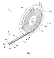
- FIG. 1 is a perspective view showing a configuration example of a reel body.
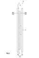
- FIG. 2 is a side view showing a configuration example of the reel unit.
- FIG. 3 is a cross-sectional view showing a configuration example of the adhesive film in the reel body.
- FIG. 4 is a cross-sectional view illustrating a configuration example of an adhesive film of a reel body according to another embodiment.
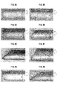
- FIG. 5 is a cross-sectional view showing an anisotropic conductive film of a reel body.
- FIG. 1 is a perspective view showing a configuration example of a reel body 1 according to the present embodiment.
- FIG. 2 is a side view showing a configuration example of the reel unit 1.
- the reel body 1 includes a reel 2 and an anisotropic conductive film (adhesive film) 3 wound around the reel 2.
- the reel 2 includes a cylindrical winding portion (core) 21 and plate-like flanges 22a and 22b (hereinafter also simply referred to as “flange 22”) provided at both ends of the winding portion 21, respectively. .
- the winding unit 21 has a shaft hole 21a into which a rotation shaft for rotating the reel 2 is inserted.
- One end of the anisotropic conductive film 3 in the longitudinal direction is connected to the winding unit 21, and the anisotropic conductive film 3 is wound around the winding unit 21.
- the winding part 21 and the flange 22 can be formed using various plastic materials, for example.
- the flange 22 may be subjected to electrostatic treatment on the surface in contact with the anisotropic conductive film 3. Examples of the method for applying the electrostatic treatment include a method of applying a compound such as polythiophene to the flange 22.
- FIG. 3 is a cross-sectional view showing a configuration example of the anisotropic conductive film 3.
- the anisotropic conductive film 3 includes a release substrate 31 and a resin layer 32 formed on the release substrate 31.
- the anisotropic conductive film 3 is formed into a tape shape, for example, and is wound around the winding portion 21 sandwiched between the flanges 22a and 22b so that the peeling base material 31 is on the outer peripheral side. In this state, it is arranged in a region formed by the winding part 21 and the flange 22.
- the release substrate 31 is formed in a tape shape, for example, by applying a release agent such as silicone to the substrate.
- the peeling substrate 31 maintains the shape of the anisotropic conductive film 3 while preventing the anisotropic conductive film 3 from drying.
- Examples of the base material used for the release base material 31 include PET (Poly Ethylene Terephthalate), OPP (Oriented Polypropylene), PMP (Poly-4-methlpentene-1), PTFE (Polytetrafluoroethylene), and the like.
- the resin layer 32 formed on the peeling substrate 31 is made of, for example, an adhesive composition, and contains an adhesive component 33 and conductive particles 34 as shown in FIG.
- the adhesive component 33 for example, a material that exhibits curability by heat or light can be used.
- a crosslinkable material such as a thermosetting resin as the adhesive component 33 because it is excellent in heat resistance and moisture resistance after connection.
- the thermosetting resin is not particularly limited as long as it has fluidity at room temperature, and examples thereof include an epoxy resin.
- An epoxy adhesive containing an epoxy resin, which is a thermosetting resin, as a main component is preferable because it can be cured for a short time, has good connection workability, and is excellent in adhesiveness.
- the epoxy resin is not particularly limited.
- naphthalene type epoxy resin biphenyl type epoxy resin, phenol novolac type epoxy resin, bisphenol type epoxy resin, stilbene type epoxy resin, triphenolmethane type epoxy resin, phenol aralkyl type epoxy resin.
- Epoxy resins may be used alone or in combination of two or more.
- conductive particles 34 known conductive particles used in the anisotropic conductive film 3 can be used.
- conductive particles 34 on the surface of particles of various metals and metal alloys such as nickel, iron, copper, aluminum, tin, lead, chromium, cobalt, silver and gold, particles of metal oxide, carbon, graphite, glass, ceramic, plastic, etc.
- grains, etc. are mentioned.
- examples of the resin particle include epoxy resin, phenol resin, acrylic resin, acrylonitrile / styrene (AS) resin, benzoguanamine resin, divinylbenzene resin, styrene resin, and the like. These particles are preferably used.
- the thickness D of the peeling substrate 31 is matched to the adhesive component of the resin layer 32 to be used and the type of the adherend. Can be selected as appropriate.
- the thickness of the release substrate 31 is preferably 30 to 80 ⁇ m. If the thickness of the release substrate 31 is less than 30 ⁇ m, the release substrate 31 may be stretched when the anisotropic conductive film 3 is pulled out strongly. You may not be able to paste.
- the resin layer 32 is likely to protrude due to the expansion and contraction of the peeling substrate 31 due to changes in temperature conditions during storage and use of the reel unit 1, or an anisotropic conductive film When pulling out 3, the resin layer 32 may fall off, which is not preferable.
- the release substrate 31 has one end 31 a in the width direction W along the length direction L, and the length direction L of the resin layer 32.
- the protrusion 31c protrudes from the one end 32a in the width direction W along the line. Further, the protruding portion 31 c is in contact with the inner surface of the flange 22 of the reel 2.
- the shape of the protrusion 31c of the peeling substrate 31 is, for example, a hemispherical shape as shown in FIG. 3A, a triangular prism shape as shown in FIGS. 3B, 3C, and 3F, and FIG. ), (E) can be used as a quadrangular prism.
- the reel unit 1 has a width between the one end 31a in the width direction W of the peeling substrate 31 and the one end 32a in the width direction W along the length direction L of the resin layer 32 (hereinafter referred to as “the peeling substrate”). It is preferable that the protrusion width A ") and the thickness D of the peeling substrate 31 satisfy the following formula (1). 0 ⁇ projection width A of peeling substrate 31 ⁇ thickness D of peeling substrate 31 (1)
- the protruding width A of the peeling substrate 31 By making the protruding width A of the peeling substrate 31 larger than 0, as described above, when the resin layer 32 flows outside the one end 32a in the width direction W of the resin layer 32, the flowing resin layer 32 is Since it is supported by the protruding portion 31c of the peeling substrate 31, the occurrence of blocking can be prevented. Further, by setting the protruding width A of the peeling substrate 31 to be equal to or less than the thickness D of the peeling substrate 31, the protruding portion 31c of the peeling substrate 31 rides on the flange 22 of the reel 2 and the anisotropic conductive film 3 warps. To prevent it.
- the reel body 1 can reliably prevent the occurrence of blocking.
- the reel unit 1 is a value obtained by dividing the thickness D of the peeling substrate 31 by the protruding width A of the peeling substrate 31, that is, (thickness D of the peeling substrate 31 / protruding width A of the peeling substrate 31).
- the protrusion 31 c of the peeling substrate 31 rides on the flange 22 of the reel 2 by setting (the thickness D of the peeling substrate 31 / the protruding width A of the peeling substrate 31) to be 1.0 or more.
- the anisotropic conductive film 3 is prevented from warping.
- blocking is prevented. Occurrence can be reliably prevented.
- blocking due to the protrusion of the resin layer 32 can be prevented by setting (the thickness D of the peeling base material 31 / the protruding width A of the peeling base material 31) to 8.0 or less.
- the peeling base 31 has one end 31 a in the width direction W along the length direction L and one end 32 a in the width direction W along the length direction L of the resin layer 32. It has the protrusion part 31c which protruded more. Further, the peeling base 31 has a protruding portion 31 c in contact with the flange 22. Thereby, in the reel unit 1, winding drawing occurs in the wound body of the anisotropic conductive film 3, and the resin layer 32 is located outside the one end 32 a in the width direction W along the length direction L of the resin layer 32. When flowing, the flowing resin layer 32 is supported by the protruding portion 31 c of the peeling substrate 31. Therefore, in the reel unit 1, the occurrence of blocking can be prevented.
- the anisotropic conductive film 3 is wound around the winding unit 21 in a state where the protruding portion 31 c of the peeling base material 31 is in contact with the flange 22.
- an adhesive that becomes the resin layer 32 is produced by dispersing the conductive particles 34 in an adhesive composed of an epoxy resin and a curing agent.
- the produced adhesive is applied on the release substrate 31 coated with a release agent so as to have a predetermined thickness, and the anisotropic conductive film 3 in which the resin layer 32 is formed on the release substrate 31 is produced.
- the produced anisotropic conductive film 3 is cut so as to satisfy the above-described formulas (1) and (2).
- the cut anisotropic conductive film 3 is wound around the winding portion 21 so that the protruding portion 31 c of the peeling substrate 31 is in contact with the inner surface of the flange 22. As described above, the reel unit 1 can be manufactured.
- the anisotropic conductive film 3 is wound around the winding unit 21 with the one end 31 a of the peeling base material 31 in contact with the flange 22. Thereby, when winding the anisotropic conductive film 3 on the reel 2, the one end 31a of the peeling base material 31 is supported on the inner surface of the flange 22, and thus the winding of the anisotropic conductive film 3 is prevented from occurring. be able to.
- the anisotropic conductive film 3 is wound around the winding portion 21 with the other end 31b of the peeling substrate 31 and the other end 32b of the resin layer 32 in contact with the inner surface of the flange 22. .
- the reel unit 1 when the overlap width between the peeling base material 31 and the resin layer 32 is narrow, a strong force is applied to the overlapping portion by preventing the occurrence of winding deviation in the anisotropic conductive film 3.
- produces by this can be prevented.
- the resin layer 32 of the anisotropic conductive film 3 is formed in a cycle of refrigeration and normal temperature received during manufacture, storage, use (transport), etc. of the reel body. Even if the tightening occurs due to expansion and contraction, the occurrence of blocking can be prevented.
- the resin layer 32 of the anisotropic conductive film 3 is made of a thermosetting resin, it is necessary to store the anisotropic conductive film 3 at 5 ° C. or less. As described above, when the anisotropic conductive film 3 is stored at 5 ° C. or less, the peeling base material 31 is contracted, so that the center portion of the anisotropic conductive film 3 wound on the reel body 1 is tightened by the tightening stress.
- the resin layer 32 may protrude.
- the reel body 1 since the protruding resin layer 32 is supported by the protruding portion 31 c of the peeling base material 31, the occurrence of blocking in the anisotropic conductive film 3 can be prevented. Therefore, even when the reel unit 1 is stored in an atmosphere of 5 ° C. or less, the anisotropic conductive film 3 can be normally pulled out from the reel 2.
- the resin layer 32 easily protrudes to the side surface.
- the protruding resin layer 32 is supported by the protruding portion 31 c of the peeling base material 31, the occurrence of blocking in the anisotropic conductive film 3 can be prevented. Therefore, even when the reel unit 1 is used under a high temperature condition, the anisotropic conductive film 3 can be normally pulled out from the reel 2.
- the anisotropic conductive film 3 is used in the reel unit 1, but is not limited to this example.
- an adhesive film that does not contain the conductive particles 34 for example, NCF (Non Conductive Film) or the like.
- an insulating adhesive film may be used.
- both surfaces of the anisotropic conductive film 3 are peeling base materials. It is good also as a structure pinched
- FIG. 4 is a cross-sectional view showing a configuration example of an anisotropic conductive film 3A according to another embodiment.
- the resin layer 32 is applied on the release substrate 31, and the release substrate 35 is further disposed on the resin layer 32.
- the peeling base material 35 for example, one having the same configuration as the peeling base material 31, that is, one having a protruding portion 35c similar to the protruding portion 31c can be used.
- the release substrate 35 and the release substrate 31 are, for example, within the range satisfying the above-described formulas (1) and (2), and the thickness of the release substrate and the release substrate.
- Example 1 In Example 1, first, 4 wt% of conductive particles were dispersed in an adhesive composed of 40 wt% solid epoxy resin, 15 wt% liquid epoxy resin, 1 wt% silane coupling agent, and 40 wt% curing agent. .
- the obtained anisotropic conductive film has a width of 1.5 mm, one end in the width direction W of the release sheet, and one end in the width direction W along the length direction L of the resin layer (hereinafter referred to as “the release sheet This is called “protrusion width.”)
- the slit was made so that A was 7 ⁇ m.
- 5A is a cross-sectional view showing the anisotropic conductive film obtained in Example 1.
- the cross-sectional shape of the anisotropic conductive film was observed with a metal microscope (product number: BX61, manufactured by Olympus Corporation).
- the slit anisotropic conductive film was wound up with the protruding portion of the release sheet in contact with the flange surface of the reel.
- FIG. 5B is a cross-sectional view showing the anisotropic conductive film obtained in Example 2.
- the thickness of the release sheet in the anisotropic conductive film is 53 ⁇ m, and the protrusion width A of the release sheet is 11 ⁇ m.
- an anisotropic conductive film having a width of 1.5 mm and a length of 300 m was obtained.
- FIG. 5C is a cross-sectional view showing the anisotropic conductive film obtained in Example 3.
- the thickness of the release sheet in the anisotropic conductive film is 53 ⁇ m, and the protrusion width A of the release sheet is 19 ⁇ m.
- an anisotropic conductive film having a width of 1.5 mm and a length of 300 m was obtained.
- FIG. 5D is a cross-sectional view showing the anisotropic conductive film obtained in Example 4.
- the thickness of the release sheet in the anisotropic conductive film was 38 ⁇ m, and the protrusion width A of the release sheet was 21 ⁇ m.
- an anisotropic conductive film having a width of 1.5 mm and a length of 300 m was obtained.
- FIG. 5E is a cross-sectional view showing the anisotropic conductive film obtained in Example 5.
- the thickness of the release sheet in the anisotropic conductive film is 53 ⁇ m
- the protrusion width A of the release sheet is 53 ⁇ m.
- an anisotropic conductive film having a width of 1.5 mm and a length of 300 m was obtained.
- FIG. 5F is a cross-sectional view showing the anisotropic conductive film obtained in Example 6.
- the thickness of the release sheet in the anisotropic conductive film is 78 ⁇ m, and the protrusion width A of the release sheet is 38 ⁇ m.
- an anisotropic conductive film having a width of 1.5 mm and a length of 300 m was obtained.
- FIG. 5G is a cross-sectional view showing the anisotropic conductive film obtained in Comparative Example 1.
- the thickness of the release sheet in the anisotropic conductive film is 53 ⁇ m
- the protrusion width A of the release sheet is 0 ⁇ m.
- an anisotropic conductive film having a width of 1.5 mm and a length of 300 m was obtained.
- FIG. 5H is a cross-sectional view showing the anisotropic conductive film obtained in Comparative Example 2.
- the thickness of the release sheet in the anisotropic conductive film was 53 ⁇ m, and the protrusion width A of the release sheet was 74 ⁇ m.
- an anisotropic conductive film having a width of 1.5 mm and a length of 300 m was obtained.
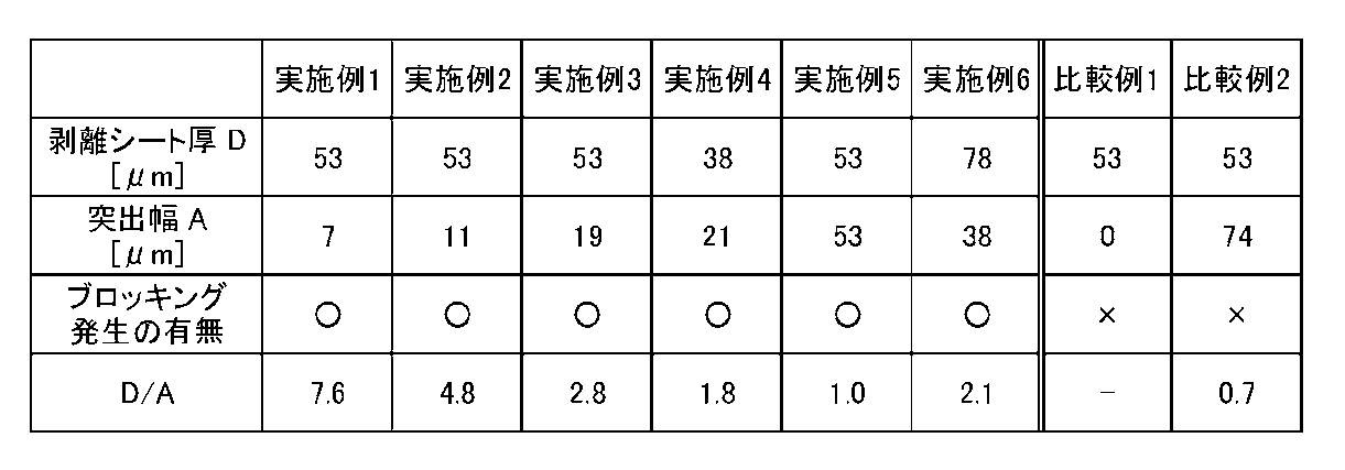
- Table 1 shows production conditions and evaluation results in Examples 1 to 6, Comparative Example 1 and Comparative Example 2.
- the anisotropic conductive films obtained in Examples 1 to 6 and Comparative Examples 1 and 2 were checked for blocking occurrence as follows. That is, a weight of 50 g was hung on the drawing end of the anisotropic conductive film, and the reel body was left in a 35 ° C. environment for 24 hours. Table 1 shows the evaluation results of the presence or absence of blocking. In Table 1, “ ⁇ ” indicates that no blocking was observed visually. Blocking “x” indicates that the occurrence of blocking was observed visually. As shown in Table 1, in Examples 1 to 6, the evaluation of blocking was “ ⁇ ”. On the other hand, in Comparative Example 1 and Comparative Example 2, the evaluation of blocking was “x”.
- the protrusion width A of the release sheet of the anisotropic conductive film was made to satisfy the above-described formulas (1) and (2).
- the resin layer of the anisotropic conductive film that was compressed by the reel drawing and protruded from the side surface of the release sheet was supported by the protruding portion of the release sheet, thereby preventing the occurrence of blocking.
Landscapes
- Chemical & Material Sciences (AREA)
- Organic Chemistry (AREA)
- Health & Medical Sciences (AREA)
- Chemical Kinetics & Catalysis (AREA)
- Medicinal Chemistry (AREA)
- Polymers & Plastics (AREA)
- Storage Of Web-Like Or Filamentary Materials (AREA)
- Adhesive Tapes (AREA)
- Adhesives Or Adhesive Processes (AREA)
- Non-Insulated Conductors (AREA)
- Laminated Bodies (AREA)
Abstract
リール体におけるブロッキングの発生を防止する。剥離基材(31)上に樹脂層(32)が形成されてなる異方性導電フィルム(3)と、異方性導電フィルムを巻取る巻取部(21)と、巻取部(21)の両側に設けられたフランジ(22)とを有するリール(2)とを備え、異方性導電フィルム(3)は、巻取部(21)に巻回され、巻取部(21)とフランジ(22)とにより形成された領域に配置されており、剥離基材(31)は、長さ方向Lに沿った幅方向Wの一端(31a)が、樹脂層(32)の長さ方向Lに沿った幅方向Wの一端(32a)よりも突出した突出部(31c)を有し、突出部(31c)がフランジ(22)に接している。
Description
本発明は、剥離基材上に樹脂層が形成された接着フィルムをリールに巻回させたリール体及びリール体の製造方法に関する。本出願は、日本国において2010年12月24日に出願された日本特許出願番号2010-287243を基礎として優先権を主張するものであり、この出願を参照することにより、本出願に援用される。
異方性導電フィルム(ACF:Anisotropic Conductive Film)は、例えば、フラットパネルディスプレイ等の用途においては、フラットパネルディスプレイ等の高精細化、狭額縁化、タクトタイム短縮、コストダウン等の要求から、幅が従来よりも狭くなり長尺化が進んでいる。
ところで、このような異方性導電フィルムは、例えば、フランジを有するリールに巻回されたリール体として使用される。このリール体においては、リールに巻回された異方性導電フィルムの巻装体が温度条件によって伸縮し、異方性導電フィルムの巻装体の巻き絞りが発生してしまう。その結果、異方性導電フィルムの樹脂層(接着剤成分)が、樹脂層の長さ方向に沿った幅方向の一端よりも外側に流動して、剥離基材の側面からはみ出してしまう。樹脂層が剥離基材の側面からはみ出してしまうと、異方性導電フィルムにおける樹脂層がリールのフランジの側面に付着してしまい、異方性導電フィルムを正常に引き出せなくなる不具合(以下、「ブロッキング」と呼ぶ)が発生してしまう。
特許文献1には、剥離基材上の中央に樹脂層を配置した異方性導電フィルムの膜構造について記載されている。しかし、このような異方性導電フィルムをリールに巻回させたリール体においては、異方性導電フィルムの巻装体において巻き絞りが発生すると、樹脂層が樹脂層の長さ方向に沿った幅方向の一端よりも外側に流動し、剥離基材の側面からはみ出してしまう。その結果、上述したブロッキングが発生してしまう。
本発明は、このような従来の実情に鑑みて提案されたものであり、ブロッキングの発生を防止することができるリール体及びリール体の製造方法を提供することを目的とする。
本発明に係るリール体は、剥離基材上に樹脂層が形成されてなる接着フィルムと、接着フィルムを巻取る巻取部と、巻取部の両側に設けられたフランジとを有するリールとを備え、接着フィルムは、巻取部に巻回され、巻取部とフランジとにより形成された領域に配置されており、剥離基材は、長さ方向に沿った幅方向の一端が、樹脂層の長さ方向に沿った幅方向の一端よりも突出した突出部を有し、突出部がフランジに接している。
本発明に係るリール体の製造方法は、剥離基材上に樹脂層が形成された接着フィルムを、巻取部と巻取部の両側に設けられたフランジとを有するリールに巻回させてリール体を製造するリール体の製造方法において、剥離基材は、長さ方向に沿った幅方向の一端が、樹脂層の長さ方向に沿った幅方向の一端よりも突出した突出部を有し、突出部がフランジに接した状態で、接着フィルムを巻取部に巻回させる。
本発明によれば、リールに巻回された接着フィルムにおいて巻き絞りが発生して、樹脂層の長さ方向に沿った幅方向の一端よりも外側に樹脂層が流動した場合に、流動した樹脂層が剥離基材の突出部で支持されるため、ブロッキングの発生を防止することができる。
以下、本発明の具体的な実施の形態(以下、「本実施の形態」という)の一例について、図面を参照しながら以下の順序で説明する。
1.リール体
2.リール体の製造方法
3.リール体の変形例
4.実施例
1.リール体
2.リール体の製造方法
3.リール体の変形例
4.実施例
<1.リール体>
図1は、本実施の形態に係るリール体1の構成例を示す斜視図である。図2は、リール体1の構成例を示す側面図である。リール体1は、リール2と、リール2に巻回された異方性導電フィルム(接着フィルム)3とを備える。
図1は、本実施の形態に係るリール体1の構成例を示す斜視図である。図2は、リール体1の構成例を示す側面図である。リール体1は、リール2と、リール2に巻回された異方性導電フィルム(接着フィルム)3とを備える。
リール2は、筒状の巻取部(巻芯)21と、巻取部21の両端にそれぞれ設けられた板状のフランジ22a,22b(以下、単に「フランジ22」とも呼ぶ。)とを備える。巻取部21は、リール2を回転させるための回転軸が挿入される軸穴21aを有する。巻取部21には、異方性導電フィルム3の長手方向の一方の端部が接続され、異方性導電フィルム3が巻回されている。巻取部21及びフランジ22は、例えば、種々のプラスチック材料を用いて形成することができる。フランジ22は、異方性導電フィルム3と接する面に、静電処理を施すようにしてもよい。静電処理を施す方法としては、例えば、ポリチオフェン等の化合物をフランジ22に塗布する方法が挙げられる。
図3は、異方性導電フィルム3の構成例を示す断面図である。異方性導電フィルム3は、剥離基材31と、剥離基材31上に形成された樹脂層32とを備える。異方性導電フィルム3は、例えば、テープ状に成型されており、フランジ22a,22bに挟持された巻取部21に、剥離基材31が外周側となるように巻回された巻装体の状態で、巻取部21とフランジ22とで形成された領域に配置されている。
剥離基材31は、例えば、基材にシリコーン等の剥離剤が塗布されており、テープ状に成型されている。剥離基材31は、異方性導電フィルム3の乾燥を防ぐとともに、異方性導電フィルム3の形状を維持する。剥離基材31に用いられる基材としては、例えば、PET(Poly Ethylene Terephthalate)、OPP(Oriented Polypropylene)、PMP(Poly-4-methlpentene-1)、PTFE(Polytetrafluoroethylene)等が挙げられる。
剥離基材31上に形成された樹脂層32は、例えば、接着剤組成物からなり、図3に示すように、接着剤成分33と導電性粒子34とを含有する。接着剤成分33としては、例えば、熱や光により硬化性を示す材料を用いることができる。特に、接続後の耐熱性や耐湿性に優れている理由から、接着剤成分33としては、熱硬化性樹脂等の架橋性材料を用いることが好ましい。熱硬化性樹脂としては、常温で流動性を有していれば特に限定されず、例えば、エポキシ樹脂が挙げられる。熱硬化性樹脂であるエポキシ樹脂を主成分として含有するエポキシ系接着剤は、短時間硬化が可能で接続作業性がよく、接着性に優れているため好ましい。
エポキシ樹脂としては、特に限定されないが、例えば、ナフタレン型エポキシ樹脂、ビフェニル型エポキシ樹脂、フェノールノボラック型エポキシ樹脂、ビスフェノール型エポキシ樹脂、スチルベン型エポキシ樹脂、トリフェノールメタン型エポキシ樹脂、フェノールアラルキル型エポキシ樹脂、ナフトール型エポキシ樹脂、ジシクロペンタジエン型エポキシ樹脂、トリフェニルメタン型エポキシ樹脂等が挙げられる。エポキシ樹脂は、単独又は2種以上を組み合わせたものであってもよい。
導電性粒子34としては、異方性導電フィルム3において使用されている公知の導電性粒子を用いることができる。例えば、ニッケル、鉄、銅、アルミニウム、錫、鉛、クロム、コバルト、銀、金等の各種金属や金属合金の粒子、金属酸化物、カーボン、グラファイト、ガラス、セラミック、プラスチック等の粒子の表面に金属をコートしたもの、これらの粒子の表面に更に絶縁薄膜をコートしたもの等が挙げられる。樹脂粒子の表面に金属をコートしたものである場合、樹脂粒子としては、例えば、エポキシ樹脂、フェノール樹脂、アクリル樹脂、アクリロニトリル・スチレン(AS)樹脂、ベンゾグアナミン樹脂、ジビニルベンゼン系樹脂、スチレン系樹脂等の粒子を用いることが好ましい。
以上のようなリール2と、異方性導電フィルム3とを備えるリール体1において、剥離基材31の厚さDは、使用する樹脂層32の接着剤成分及び被接着物の種類等に合わせて適宜選択することができる。例えば、剥離基材31の厚さは、30~80μmとすることが好ましい。剥離基材31の厚さを30μm未満とすると、異方性導電フィルム3を強く引き出したときに、剥離基材31が伸びてしまうことがあり、適切な長さの異方性導電フィルム3を貼り付けることが出来ないことがある。剥離基材31の厚さが80μmを超えると、リール体1の保管や使用時の温度条件の変化による剥離基材31の伸縮の影響によって樹脂層32がはみ出し易くなったり、異方性導電フィルム3を引き出す際に樹脂層32が脱落することがあり、好ましくない。
また、図1及び図3に示すように、異方性導電フィルム3において、剥離基材31は、その長さ方向Lに沿った幅方向Wの一端31aが、樹脂層32の長さ方向Lに沿った幅方向Wの一端32aよりも突出した突出部31cを有する。また、突出部31cは、リール2のフランジ22の内面に接している。これにより、異方性導電フィルム3の巻装体において巻き絞りが発生し、樹脂層32の長さ方向Lに沿った幅方向Wの一端32aよりも外側に樹脂層32が流動した場合に、流動した樹脂層32が剥離基材31の突出部31cで支持される。したがって、リール体1では、ブロッキングの発生を防止することができる。
剥離基材31の突出部31cの形状は、例えば、図3(A)に示すような半球状、図3(B),(C),(F)に示すような三角柱状、図3(D),(E)に示すような四角柱状とすることができる。
また、リール体1は、剥離基材31の幅方向Wの一端31aと、樹脂層32の長さ方向Lに沿った幅方向Wの一端32aとの間の幅(以下、「剥離基材の突出幅A」と呼ぶ。)と、剥離基材31の厚さDとが、下記式(1)を満たすようにすることが好ましい。
0<剥離基材31の突出幅A≦剥離基材31の厚さD (1)
0<剥離基材31の突出幅A≦剥離基材31の厚さD (1)
剥離基材31の突出幅Aを0よりも大きくすることにより、上述の如く、樹脂層32の幅方向Wの一端32aよりも外側に樹脂層32が流動した場合に、流動した樹脂層32が剥離基材31の突出部31cで支持されるため、ブロッキングの発生を防止することができる。また、剥離基材31の突出幅Aを剥離基材31の厚さD以下とすることにより、剥離基材31の突出部31cがリール2のフランジ22に乗り上げて異方性導電フィルム3が反ってしまうことを防止する。これにより、異方性導電フィルム3の巻装体において力の加わり方が不均一となり、樹脂層32が剥離基材31の一端31aからはみ出してしまうことを防止することができる。したがって、リール体1では、ブロッキングの発生を確実に防止することができる。
また、リール体1は、剥離基材31の厚さDを剥離基材31の突出幅Aで除した値、すなわち、(剥離基材31の厚さD/剥離基材31の突出幅A)が、下記式(2)を満たすことが好ましい。
1.0≦(剥離基材31の厚さD/剥離基材31の突出幅A)≦8.0(2)
1.0≦(剥離基材31の厚さD/剥離基材31の突出幅A)≦8.0(2)
リール体1において、(剥離基材31の厚さD/剥離基材31の突出幅A)を1.0以上とすることにより、剥離基材31の突出部31cがリール2のフランジ22に乗り上げて異方性導電フィルム3が反ってしまうことを防止する。これにより、異方性導電フィルム3の巻装体における力の加わり方が不均一となって樹脂層32が剥離基材31の一端31aからはみ出してしまうことを防止することができるため、ブロッキングの発生を確実に防止することができる。また、リール体1において、(剥離基材31の厚さD/剥離基材31の突出幅A)を8.0以下とすることにより、樹脂層32のはみ出しによるブロッキングを防ぐことができる。
以上説明したように、リール体1において、剥離基材31は、その長さ方向Lに沿った幅方向Wの一端31aが、樹脂層32の長さ方向Lに沿った幅方向Wの一端32aよりも突出した突出部31cを有する。また、剥離基材31は、突出部31cがフランジ22に接している。これにより、リール体1は、異方性導電フィルム3の巻装体において巻き絞りが発生し、樹脂層32の長さ方向Lに沿った幅方向Wの一端32aよりも外側に樹脂層32が流動した場合に、流動した樹脂層32が剥離基材31の突出部31cで支持される。したがって、リール体1では、ブロッキングの発生を防止することができる。
<2.リール体の製造方法>
続いて、上述したリール体1の製造方法の一例について説明する。本実施の形態に係るリール体1の製造方法では、剥離基材31の突出部31cがフランジ22に接した状態で、異方性導電フィルム3を巻取部21に巻回させる。
続いて、上述したリール体1の製造方法の一例について説明する。本実施の形態に係るリール体1の製造方法では、剥離基材31の突出部31cがフランジ22に接した状態で、異方性導電フィルム3を巻取部21に巻回させる。
例えば、まず、エポキシ樹脂と硬化剤とで構成された接着剤中に導電性粒子34を分散させて樹脂層32となる接着剤を作製する。作製した接着剤を、剥離剤が塗布された剥離基材31上に所定の厚さとなるように塗布して、剥離基材31上に樹脂層32が形成された異方性導電フィルム3を作製する。上述した式(1)及び式(2)を満たすように、作製した異方性導電フィルム3を切断する。切断した異方性導電フィルム3を、剥離基材31の突出部31cがフランジ22の内面に接するようにしながら巻取部21に巻取る。以上のようにして、リール体1を製造することができる。
リール体1の製造方法では、剥離基材31の一端31aをフランジ22に接した状態で異方性導電フィルム3を巻取部21に巻取るようにしている。これにより、異方性導電フィルム3をリール2に巻取る際に、剥離基材31の一端31aがフランジ22の内面に支持されるため、異方性導電フィルム3の巻きズレの発生を防止することができる。
また、リール体1の製造方法では、剥離基材31の長さ方向Lに沿った幅方向Wの他端31bと、樹脂層32の長さ方向Lに沿った幅方向Wの他端32bとを一致させ、且つ、剥離基材31の他端31bと樹脂層32の他端32bとがフランジ22の内面に接した状態で異方性導電フィルム3を巻取部21に巻取ることが好ましい。これにより、異方性導電フィルム3をリール2に巻取る際に、剥離基材31の他端31bと樹脂層32の他端32bとがフランジ22の内面に支持されるため、異方性導電フィルム3の巻きズレの発生をより確実に防止することができる。
さらに、リール体1においては、異方性導電フィルム3における巻きズレの発生を防止することにより、剥離基材31と樹脂層32との重なり幅が狭い場合に、その重なり部分に強い力が加わることによって発生するブロッキングを防止することができる。
以上のように説明したリール体1では、例えば、リール体の製造時、保管時、使用時(輸送時)等に受ける冷蔵と常温とのサイクルで、異方性導電フィルム3の樹脂層32が伸縮することにより巻き締まりが発生しても、ブロッキングの発生を防止することができる。
例えば、異方性導電フィルム3の樹脂層32が、熱硬化性樹脂で構成されている場合には、5℃以下で異方性導電フィルム3を保管する必要がある。このように、5℃以下で異方性導電フィルム3を保管すると、剥離基材31が収縮することによって、リール体1において巻回された異方性導電フィルム3の中心部から、締め付け応力によって樹脂層32がはみ出してしまうことがある。
一方、リール体1によれば、はみ出した樹脂層32が剥離基材31の突出部31cで支持されるため、異方性導電フィルム3におけるブロッキングの発生を防止することができる。したがって、リール体1は、5℃以下の雰囲気で保管された場合でも、異方性導電フィルム3をリール2から正常に引出すことができる。
また、例えば、高温条件下(例えば、30℃以上)でリール体1が使用される場合には、樹脂層32が側面にはみ出し易くなる。しかし、リール体1では、はみ出した樹脂層32が剥離基材31の突出部31cで支持されるため、異方性導電フィルム3におけるブロッキングの発生を防止することができる。したがって、リール体1は、高温条件下で使用された場合でも、異方性導電フィルム3をリール2から正常に引出すことができる。
<3.リール体の変形例>
上述した説明では、リール体1において異方性導電フィルム3を用いるものとしたが、この例に限定されず、例えば、導電性粒子34を含有しない接着フィルム、例えば、NCF(Non Conductive Film)等の絶縁性接着フィルムを用いてもよい。
上述した説明では、リール体1において異方性導電フィルム3を用いるものとしたが、この例に限定されず、例えば、導電性粒子34を含有しない接着フィルム、例えば、NCF(Non Conductive Film)等の絶縁性接着フィルムを用いてもよい。
また、上述した説明では、剥離基材31上に樹脂層32が形成された異方性導電フィルム3について説明したが、この例に限定されず、異方性導電フィルム3の両面が剥離基材31によって挟まれた構成としてもよい。
図4は、他の実施の形態に係る異方性導電フィルム3Aの構成例を示す断面図である。異方性導電フィルム3Aは、剥離基材31上に樹脂層32が塗布されており、樹脂層32上に剥離基材35がさらに配置されている。剥離基材35としては、例えば、剥離基材31と同じ構成のもの、すなわち、突出部31cと同様の突出部35cを有するものを用いることができる。また、異方性導電フィルム3Aにおいて、剥離基材35及び剥離基材31は、例えば、上述した式(1)及び式(2)を満たす範囲で、剥離基材の厚さ、剥離基材の突出部の形状、剥離基材の突出幅を変更してもよい。なお、図4に示す異方性導電フィルム3Aにおいて、上述した異方性導電フィルム3と同一の構成については同一の符号を付し、その詳細な説明を省略するものとする。
以下、本発明の具体的な実施例について説明する。なお、下記の実施例に本発明の範囲が限定されるものではない。
(実施例1)
実施例1では、まず、固形エポキシ樹脂40wt%と、液状エポキシ樹脂15wt%と、シランカップリング剤1wt%と、硬化剤40wt%とからなる接着剤中に、導電性粒子を4wt%分散させた。
・固形エポキシ樹脂(品名:EP1003、ジャパンエポキシレジン社製)
・液状エポキシ樹脂(品名:EP828、ジャパンエポキシレジン社製)
・シランカップリング剤(品名:KBE-403、信越化学工業社製)
・硬化剤(品名:ノバキュアHX3941、旭化成イーマテリアルズ社製)
・導電性粒子(品名:AUL704、積水化学工業社製)
実施例1では、まず、固形エポキシ樹脂40wt%と、液状エポキシ樹脂15wt%と、シランカップリング剤1wt%と、硬化剤40wt%とからなる接着剤中に、導電性粒子を4wt%分散させた。
・固形エポキシ樹脂(品名:EP1003、ジャパンエポキシレジン社製)
・液状エポキシ樹脂(品名:EP828、ジャパンエポキシレジン社製)
・シランカップリング剤(品名:KBE-403、信越化学工業社製)
・硬化剤(品名:ノバキュアHX3941、旭化成イーマテリアルズ社製)
・導電性粒子(品名:AUL704、積水化学工業社製)
PET基材の表裏両面に剥離力の異なるシリコーン系剥離剤が塗布された厚さが53μmの剥離シートの重剥離面上に、導電性粒子が分散された接着剤を厚みが18μmになるように塗布し、300mの長さのシート状の異方性導電フィルムを巻き取った。
得られた異方性導電フィルムを、幅1.5mm、剥離シートの幅方向Wの一端と、樹脂層の長さ方向Lに沿った幅方向Wの一端との幅(以下、「剥離シートの突出幅」と呼ぶ。)Aが7μmとなるようにスリットした。図5(A)は、実施例1で得られた異方性導電フィルムを示す断面図である。異方性導電フィルムの断面形状は、金属顕微鏡(品番:BX61、オリンパス社製)で観察した。スリットした異方性導電フィルムを剥離シートの突出部がリールのフランジ面に接した状態で巻き取った。
(実施例2)
図5(B)は、実施例2で得られた異方性導電フィルムを示す断面図である。実施例2では、図5(B)に示すように、異方性導電フィルムにおける剥離シートの厚さが53μm、剥離シートの突出幅Aが11μmとなるようにしたこと以外は、実施例1と同様にして、幅1.5mm、長さ300mの異方性導電フィルムを得た。
図5(B)は、実施例2で得られた異方性導電フィルムを示す断面図である。実施例2では、図5(B)に示すように、異方性導電フィルムにおける剥離シートの厚さが53μm、剥離シートの突出幅Aが11μmとなるようにしたこと以外は、実施例1と同様にして、幅1.5mm、長さ300mの異方性導電フィルムを得た。
(実施例3)
図5(C)は、実施例3で得られた異方性導電フィルムを示す断面図である。実施例3では、図5(C)に示すように、異方性導電フィルムにおける剥離シートの厚さが53μm、剥離シートの突出幅Aが19μmとなるようにしたこと以外は、実施例1と同様にして、幅1.5mm、長さ300mの異方性導電フィルムを得た。
図5(C)は、実施例3で得られた異方性導電フィルムを示す断面図である。実施例3では、図5(C)に示すように、異方性導電フィルムにおける剥離シートの厚さが53μm、剥離シートの突出幅Aが19μmとなるようにしたこと以外は、実施例1と同様にして、幅1.5mm、長さ300mの異方性導電フィルムを得た。
(実施例4)
図5(D)は、実施例4で得られた異方性導電フィルムを示す断面図である。実施例4では、図5(D)に示すように、異方性導電フィルムにおける剥離シートの厚さが38μm、剥離シートの突出幅Aが21μmとなるようにしたこと以外は、実施例1と同様にして、幅1.5mm、長さ300mの異方性導電フィルムを得た。
図5(D)は、実施例4で得られた異方性導電フィルムを示す断面図である。実施例4では、図5(D)に示すように、異方性導電フィルムにおける剥離シートの厚さが38μm、剥離シートの突出幅Aが21μmとなるようにしたこと以外は、実施例1と同様にして、幅1.5mm、長さ300mの異方性導電フィルムを得た。
(実施例5)
図5(E)は、実施例5で得られた異方性導電フィルムを示す断面図である。実施例5では、図5(E)に示すように、異方性導電フィルムにおける剥離シートの厚さが53μm、剥離シートの突出幅Aが53μmとなるようにしたこと以外は、実施例1と同様にして、幅1.5mm、長さ300mの異方性導電フィルムを得た。
図5(E)は、実施例5で得られた異方性導電フィルムを示す断面図である。実施例5では、図5(E)に示すように、異方性導電フィルムにおける剥離シートの厚さが53μm、剥離シートの突出幅Aが53μmとなるようにしたこと以外は、実施例1と同様にして、幅1.5mm、長さ300mの異方性導電フィルムを得た。
(実施例6)
図5(F)は、実施例6で得られた異方性導電フィルムを示す断面図である。実施例6では、図5(F)に示すように、異方性導電フィルムにおける剥離シートの厚さが78μm、剥離シートの突出幅Aが38μmとなるようにしたこと以外は、実施例1と同様にして、幅1.5mm、長さ300mの異方性導電フィルムを得た。
図5(F)は、実施例6で得られた異方性導電フィルムを示す断面図である。実施例6では、図5(F)に示すように、異方性導電フィルムにおける剥離シートの厚さが78μm、剥離シートの突出幅Aが38μmとなるようにしたこと以外は、実施例1と同様にして、幅1.5mm、長さ300mの異方性導電フィルムを得た。
(比較例1)
図5(G)は、比較例1で得られた異方性導電フィルムを示す断面図である。比較例1では、図5(G)に示すように、異方性導電フィルムにおける剥離シートの厚さが53μm、剥離シートの突出幅Aが0μmとなるようにしたこと以外は、実施例1と同様にして、幅1.5mm、長さ300mの異方性導電フィルムを得た。
図5(G)は、比較例1で得られた異方性導電フィルムを示す断面図である。比較例1では、図5(G)に示すように、異方性導電フィルムにおける剥離シートの厚さが53μm、剥離シートの突出幅Aが0μmとなるようにしたこと以外は、実施例1と同様にして、幅1.5mm、長さ300mの異方性導電フィルムを得た。
(比較例2)
図5(H)は、比較例2で得られた異方性導電フィルムを示す断面図である。比較例2では、図5(H)に示すように、異方性導電フィルムにおける剥離シートの厚さが53μm、剥離シートの突出幅Aが74μmとなるようにしたこと以外は、実施例1と同様にして、幅1.5mm、長さ300mの異方性導電フィルムを得た。
図5(H)は、比較例2で得られた異方性導電フィルムを示す断面図である。比較例2では、図5(H)に示すように、異方性導電フィルムにおける剥離シートの厚さが53μm、剥離シートの突出幅Aが74μmとなるようにしたこと以外は、実施例1と同様にして、幅1.5mm、長さ300mの異方性導電フィルムを得た。
表1に、実施例1~実施例6、比較例1及び比較例2における作製条件及び評価結果を示す。
(ブロッキング発生の有無の評価)
実施例1~実施例6及び比較例1、比較例2で得られた異方性導電フィルムのブロッキング発生の有無は、次のようにして行った。すなわち、異方性導電フィルムの引出し末端部に50gの重りをぶら下げ、リール体を35℃環境下に24時間放置した後に異方性導電フィルムを300m全て引き出して、ブロッキング発生の有無を評価した。ブロッキング発生の有無の評価結果を表1に示す。表1において、ブロッキングが「○」とは、目視にて、ブロッキングの発生が認められなかったことを示す。ブロッキングが「×」とは、目視にて、ブロッキングの発生が認められたことを示す。表1に示すように、実施例1~実施例6では、ブロッキングの評価が「○」であった。一方、比較例1及び比較例2では、ブロッキングの評価が「×」であった。
実施例1~実施例6及び比較例1、比較例2で得られた異方性導電フィルムのブロッキング発生の有無は、次のようにして行った。すなわち、異方性導電フィルムの引出し末端部に50gの重りをぶら下げ、リール体を35℃環境下に24時間放置した後に異方性導電フィルムを300m全て引き出して、ブロッキング発生の有無を評価した。ブロッキング発生の有無の評価結果を表1に示す。表1において、ブロッキングが「○」とは、目視にて、ブロッキングの発生が認められなかったことを示す。ブロッキングが「×」とは、目視にて、ブロッキングの発生が認められたことを示す。表1に示すように、実施例1~実施例6では、ブロッキングの評価が「○」であった。一方、比較例1及び比較例2では、ブロッキングの評価が「×」であった。
比較例1では、剥離シートの突出幅Aが、上述した式(1)及び式(2)を満たしていないため、ブロッキングが発生し、異方性導電フィルムを約280m引出した地点で、異方性導電フィルムが剥離シートから剥離した。また、比較例2では、異方性剥離シートの突出幅Aが、上述した式(1)及び式(2)を満たしていないため、異方性導電フィルムをリールに巻取る際に、リールのフランジに剥離シートの突出部が乗り上げてしまい、異方性導電フィルムが反ってしまった。これにより、異方性導電フィルムの巻装体における力の加わり方が不均一となって樹脂層が剥離シートの一端からはみ出してしまい、ブロッキングが発生した。
一方、実施例1~実施例6では、異方性導電フィルムの剥離シートの突出幅Aが、上述した式(1)及び式(2)を満たすようにした。これにより、リールの巻き絞りにより圧縮されて剥離シートの側面からはみ出した異方性導電フィルムの樹脂層が剥離シートの突出部で支持され、ブロッキングの発生を防止することができた。
Claims (7)
- 剥離基材上に樹脂層が形成されてなる接着フィルムと、
前記接着フィルムを巻取る巻取部と、該巻取部の両側に設けられたフランジとを有するリールとを備え、
前記接着フィルムは、前記巻取部に巻回され、該巻取部と前記フランジとにより形成された領域に配置されており、
前記剥離基材は、長さ方向に沿った幅方向の一端が、前記樹脂層の長さ方向に沿った幅方向の一端よりも突出した突出部を有し、該突出部が前記フランジに接しているリール体。 - 前記樹脂層の長さ方向に沿った幅方向の一端と、前記剥離基材の長さ方向に沿った幅方向の一端との間の幅をA、該剥離基材の厚さをDとした場合に、A≦Dを満たす請求項1記載のリール体。
- (前記剥離基材の厚さ)/(前記剥離基材の突出幅)が1.0~8.0である請求項1又は2記載のリール体。
- 前記剥離基材の厚さが、30~80μmである請求項1乃至3のうちいずれか1項記載のリール体。
- 前記接着フィルムは、剥離基材上に導電性粒子を含有する樹脂層が積層された異方性導電フィルムである請求項1乃至4のうちいずれか1項記載のリール体。
- 前記接着フィルムは、前記剥離基材の長さ方向に沿った幅方向の他端と、前記樹脂層の長さ方向に沿った幅方向の他端とが一致するとともに、該剥離基材の他端と該樹脂層の他端とが前記フランジに接している請求項1乃至5のうちいずれか1項記載のリール体。
- 剥離基材上に樹脂層が形成された接着フィルムを、巻取部と該巻取部の両側に設けられたフランジとを有するリールに巻回させてリール体を製造するリール体の製造方法において、
前記剥離基材は、長さ方向に沿った幅方向の一端が、前記樹脂層の長さ方向に沿った幅方向の一端よりも突出した突出部を有し、
前記突出部が前記フランジに接した状態で、前記接着フィルムを前記巻取部に巻回させるリール体の製造方法。
Priority Applications (3)
| Application Number | Priority Date | Filing Date | Title |
|---|---|---|---|
| CN201180062347.3A CN103270124B (zh) | 2010-12-24 | 2011-12-22 | 卷盘体及卷盘体的制造方法 |
| HK13112922.3A HK1185632B (en) | 2010-12-24 | 2011-12-22 | Reel body and process for production of reel body |
| KR1020137013471A KR101909300B1 (ko) | 2010-12-24 | 2011-12-22 | 릴체 및 릴체의 제조 방법 |
Applications Claiming Priority (2)
| Application Number | Priority Date | Filing Date | Title |
|---|---|---|---|
| JP2010-287243 | 2010-12-24 | ||
| JP2010287243A JP5759168B2 (ja) | 2010-12-24 | 2010-12-24 | リール体及びリール体の製造方法 |
Publications (1)
| Publication Number | Publication Date |
|---|---|
| WO2012086770A1 true WO2012086770A1 (ja) | 2012-06-28 |
Family
ID=43945966
Family Applications (1)
| Application Number | Title | Priority Date | Filing Date |
|---|---|---|---|
| PCT/JP2011/079854 Ceased WO2012086770A1 (ja) | 2010-12-24 | 2011-12-22 | リール体及びリール体の製造方法 |
Country Status (5)
| Country | Link |
|---|---|
| JP (1) | JP5759168B2 (ja) |
| KR (1) | KR101909300B1 (ja) |
| CN (1) | CN103270124B (ja) |
| TW (1) | TWI527704B (ja) |
| WO (1) | WO2012086770A1 (ja) |
Cited By (1)
| Publication number | Priority date | Publication date | Assignee | Title |
|---|---|---|---|---|
| CN104203789A (zh) * | 2012-04-06 | 2014-12-10 | 迪睿合电子材料有限公司 | 卷盘部件、粘接膜的卷绕方法、粘接膜的卷出方法 |
Families Citing this family (11)
| Publication number | Priority date | Publication date | Assignee | Title |
|---|---|---|---|---|
| JP5912700B2 (ja) * | 2012-03-14 | 2016-04-27 | デクセリアルズ株式会社 | リール部材、接着フィルムの巻回方法及び巻き出し方法 |
| JP5981173B2 (ja) * | 2012-03-14 | 2016-08-31 | デクセリアルズ株式会社 | 接続体の製造方法、接着フィルムの貼り合わせ方法、接着フィルムの引き出し方法及び接着フィルム |
| JP5982158B2 (ja) | 2012-04-06 | 2016-08-31 | デクセリアルズ株式会社 | リール部材 |
| JP6197395B2 (ja) * | 2012-07-20 | 2017-09-20 | 日立化成株式会社 | 接着テープ用リール及びテープ |
| JP5888510B2 (ja) * | 2012-09-27 | 2016-03-22 | ブラザー工業株式会社 | 巻芯部材 |
| JP5991117B2 (ja) * | 2012-09-27 | 2016-09-14 | ブラザー工業株式会社 | テープ巻き取り装置 |
| JP2015086029A (ja) * | 2013-10-29 | 2015-05-07 | デクセリアルズ株式会社 | リール部材及びフィルム収容体 |
| JP6640538B2 (ja) * | 2015-11-20 | 2020-02-05 | デクセリアルズ株式会社 | フィルム巻装体、及びフィルム巻装体の製造方法 |
| JP6829998B2 (ja) * | 2017-01-25 | 2021-02-17 | 日東シンコー株式会社 | 基材付接着シート及び半導体モジュール |
| KR102256783B1 (ko) * | 2018-11-22 | 2021-05-26 | 주식회사 엘지화학 | 폴더블 백플레이트 필름 및 폴더블 백플레이트 필름의 제조방법 |
| KR102972498B1 (ko) | 2024-11-19 | 2026-06-02 | 이상민 | 고순도 bpf와 협분산 페놀 노볼락 수지의 동시적 제조 방법 및 이를 포함하는 조성물 |
Citations (3)
| Publication number | Priority date | Publication date | Assignee | Title |
|---|---|---|---|---|
| JP2003142176A (ja) * | 2001-10-31 | 2003-05-16 | Optrex Corp | 異方性導電膜構造 |
| WO2007015372A1 (ja) * | 2005-08-04 | 2007-02-08 | Hitachi Chemical Co., Ltd. | 異方導電フィルム及びその製造方法 |
| WO2008053824A1 (en) * | 2006-10-31 | 2008-05-08 | Hitachi Chemical Company, Ltd. | Adhesive tape and adhesive tape roll |
Family Cites Families (4)
| Publication number | Priority date | Publication date | Assignee | Title |
|---|---|---|---|---|
| JP2003001421A (ja) * | 2001-06-25 | 2003-01-08 | Minato Kogyo Kk | 溶接機の溶接用ワイヤ送給装置 |
| JP2008303067A (ja) * | 2007-05-09 | 2008-12-18 | Hitachi Chem Co Ltd | 接着材リール及びこれを用いた回路接続体の製造方法 |
| JP5104034B2 (ja) * | 2007-05-23 | 2012-12-19 | 日立化成工業株式会社 | 異方導電接続用フィルム及びリール体 |
| JP5400357B2 (ja) * | 2008-11-13 | 2014-01-29 | 日東電工株式会社 | 粘着テープ巻回体 |
-
2010
- 2010-12-24 JP JP2010287243A patent/JP5759168B2/ja active Active
-
2011
- 2011-12-22 KR KR1020137013471A patent/KR101909300B1/ko active Active
- 2011-12-22 CN CN201180062347.3A patent/CN103270124B/zh active Active
- 2011-12-22 WO PCT/JP2011/079854 patent/WO2012086770A1/ja not_active Ceased
- 2011-12-23 TW TW100148175A patent/TWI527704B/zh active
Patent Citations (3)
| Publication number | Priority date | Publication date | Assignee | Title |
|---|---|---|---|---|
| JP2003142176A (ja) * | 2001-10-31 | 2003-05-16 | Optrex Corp | 異方性導電膜構造 |
| WO2007015372A1 (ja) * | 2005-08-04 | 2007-02-08 | Hitachi Chemical Co., Ltd. | 異方導電フィルム及びその製造方法 |
| WO2008053824A1 (en) * | 2006-10-31 | 2008-05-08 | Hitachi Chemical Company, Ltd. | Adhesive tape and adhesive tape roll |
Cited By (2)
| Publication number | Priority date | Publication date | Assignee | Title |
|---|---|---|---|---|
| CN104203789A (zh) * | 2012-04-06 | 2014-12-10 | 迪睿合电子材料有限公司 | 卷盘部件、粘接膜的卷绕方法、粘接膜的卷出方法 |
| CN104203789B (zh) * | 2012-04-06 | 2016-10-05 | 迪睿合电子材料有限公司 | 卷盘部件、粘接膜的卷绕方法、粘接膜的卷出方法 |
Also Published As
| Publication number | Publication date |
|---|---|
| HK1185632A1 (en) | 2014-02-21 |
| KR101909300B1 (ko) | 2018-10-17 |
| KR20130143066A (ko) | 2013-12-30 |
| CN103270124B (zh) | 2015-09-09 |
| JP2011058007A (ja) | 2011-03-24 |
| JP5759168B2 (ja) | 2015-08-05 |
| CN103270124A (zh) | 2013-08-28 |
| TW201236879A (en) | 2012-09-16 |
| TWI527704B (zh) | 2016-04-01 |
Similar Documents
| Publication | Publication Date | Title |
|---|---|---|
| JP5759168B2 (ja) | リール体及びリール体の製造方法 | |
| TW201631086A (zh) | 黏著片材及光學構件 | |
| TWI802744B (zh) | 薄片狀導電構件 | |
| US11008488B2 (en) | Adhesive composition and film roll | |
| WO2018061567A1 (ja) | 接着フィルム巻装体、接着フィルム巻装体の製造方法 | |
| KR102268491B1 (ko) | 릴 부재, 접착 필름의 권회 방법, 접착 필름의 권출 방법 | |
| JP7446095B2 (ja) | フィルム巻装体及び接続体の製造方法 | |
| TWI567016B (zh) | Reel components | |
| JP6297381B2 (ja) | 接着フィルム、フィルム巻装体、接続体の製造方法 | |
| JP2017137188A (ja) | フィルム巻装体のはみ出し試験方法 | |
| HK1185632B (en) | Reel body and process for production of reel body | |
| JP7762658B2 (ja) | 電気剥離性粘着シート、及び電気剥離性粘着シートの使用方法 | |
| WO2015053355A1 (ja) | 接着フィルム、フィルム巻装体、接続構造体の製造方法、接続方法、接続構造体 | |
| JP2012102278A (ja) | リール体及びその製造方法、接着フィルムの平坦化方法 | |
| JP6524283B2 (ja) | 接着フィルム、フィルム巻装体、接続体の製造方法 | |
| JP2015189836A (ja) | 接着フィルム巻装体、接続体の製造方法及び電子部品の接続方法 | |
| JP5912700B2 (ja) | リール部材、接着フィルムの巻回方法及び巻き出し方法 |
Legal Events
| Date | Code | Title | Description |
|---|---|---|---|
| 121 | Ep: the epo has been informed by wipo that ep was designated in this application |
Ref document number: 11852037 Country of ref document: EP Kind code of ref document: A1 |
|
| DPE2 | Request for preliminary examination filed before expiration of 19th month from priority date (pct application filed from 20040101) | ||
| ENP | Entry into the national phase |
Ref document number: 20137013471 Country of ref document: KR Kind code of ref document: A |
|
| NENP | Non-entry into the national phase |
Ref country code: DE |
|
| 122 | Ep: pct application non-entry in european phase |
Ref document number: 11852037 Country of ref document: EP Kind code of ref document: A1 |