WO2012086249A1 - ショット処理装置 - Google Patents
ショット処理装置 Download PDFInfo
- Publication number
- WO2012086249A1 WO2012086249A1 PCT/JP2011/066719 JP2011066719W WO2012086249A1 WO 2012086249 A1 WO2012086249 A1 WO 2012086249A1 JP 2011066719 W JP2011066719 W JP 2011066719W WO 2012086249 A1 WO2012086249 A1 WO 2012086249A1
- Authority
- WO
- WIPO (PCT)
- Prior art keywords
- unit
- shot
- storage tank
- shot material
- storage tanks
- Prior art date
- Legal status (The legal status is an assumption and is not a legal conclusion. Google has not performed a legal analysis and makes no representation as to the accuracy of the status listed.)
- Ceased
Links
Images






Classifications
-
- B—PERFORMING OPERATIONS; TRANSPORTING
- B24—GRINDING; POLISHING
- B24C—ABRASIVE OR RELATED BLASTING WITH PARTICULATE MATERIAL
- B24C11/00—Selection of abrasive materials or additives for abrasive blasts
-
- B—PERFORMING OPERATIONS; TRANSPORTING
- B24—GRINDING; POLISHING
- B24C—ABRASIVE OR RELATED BLASTING WITH PARTICULATE MATERIAL
- B24C7/00—Equipment for feeding abrasive material; Controlling the flowability, constitution, or other physical characteristics of abrasive blasts
Definitions
- the present invention relates to a shot processing apparatus.
- the present invention has been made in view of the above problems, and provides a shot processing apparatus capable of improving work efficiency while suppressing costs even when a workpiece is shot by changing the particle size of the shot material.
- the purpose is to do.
- a shot processing apparatus includes a plurality of storage tanks for storing a plurality of types of shot materials each having a different particle size classification, A projection unit that projects the shot material supplied from each of the storage tanks, and a charging path that connects the plurality of storage tanks and the projection unit; and the shot material is applied to the projection unit among the plurality of storage tanks.
- a storage tank switching unit that switches a storage tank to be supplied, a transport unit that transports the shot material projected from the projection unit, and a shot material that is connected to the transport unit via a return path and transported by the transport unit. And sieving based on the particle size classification and returning to the original storage tank among the plurality of storage tanks.
- the shot material is supplied from one of the plurality of storage tanks to the projection unit, and the shot material is projected from the projection unit onto the workpiece. Moreover, after the shot material projected toward the workpiece is transported by the transport unit, it is screened based on the particle size classification in the screen and returned to the original storage tank among the plurality of storage tanks.
- the storage tank switching unit sequentially switches the storage tanks that supply the shot material to the projection unit among the plurality of storage tanks, thereby performing a plurality of shot processing steps using a plurality of types of shot materials in order.
- a shot processing apparatus is the shot processing apparatus according to the first aspect of the present invention, wherein the shot processing apparatus has a start operation unit for a start operation by an operator, and the start operation unit is a start operation.
- An operation unit that outputs an activation signal when the activation signal is detected, and when the activation signal is detected, the projection unit and the transport unit are operated, and the shot material is supplied to the projection unit among the plurality of storage tanks.
- a control unit that controls a switching state of the storage tank switching unit so that the storage tank is switched for each shot processing step, and executes a plurality of shot processing steps using the plurality of types of shot materials in order. ing.
- this shot processing apparatus it is possible to automatically execute a plurality of shot processing steps using a plurality of types of shot materials in order only by an operator starting the start operation unit. Thereby, working efficiency can be improved more.
- the shot processing apparatus is the shot processing apparatus according to the second aspect of the present invention, wherein the order of the storage tanks that supply the shot material to the projection unit among the plurality of storage tanks is in advance.
- a supply pattern selection signal corresponding to the selection operation of the operation unit is output, and the control unit is configured to supply shot material from the plurality of storage tanks to the projection unit in an order corresponding to the supply pattern selection signal. It is set as the structure which controls the switching state of the said storage tank switching part.
- this shot processing apparatus an operator can change the order of shot materials to be projected among a plurality of types of shot materials by selecting and operating a supply pattern selection operation unit. Thereby, the usability of the shot processing apparatus can be improved.
- the shot processing apparatus is the shot processing apparatus according to the second aspect or the third aspect of the present invention, wherein the operation unit is configured to project the projection among the plurality of storage tanks by an operator.
- a storage tank selection operation unit for selecting and operating a storage tank for supplying shot material to the unit, and outputting a storage tank selection signal according to a selection operation of the storage tank selection operation unit, It is set as the structure which controls the switching state of the said storage tank switching part so that a shot material may be supplied to the said projection unit from the storage tank corresponding to the said storage tank selection signal among several storage tanks.
- the operator can select and use one of a plurality of types of shot materials by selecting and operating the storage tank selection operation section. Thereby, the usability of the shot processing apparatus can be improved.
- a shot processing apparatus is the shot processing apparatus according to any one of the first to third aspects of the present invention, wherein the input path and the projection path are between the transport unit and the projection unit. Switching between a direct connection path provided in parallel with the reduction path, a state in which the shot material flows from the conveyance unit to the sieve through the reduction path, and a state in which the shot material flows from the conveyance unit to the projection unit through the direct connection path And a direct operation switching unit.
- this shot processing apparatus it is possible to perform shot processing by directly supplying the shot material from the transport unit to the projection unit without passing through the sieve. Accordingly, for example, it is possible to perform shot processing using a mixture of a plurality of types of shot materials.
- a shot processing apparatus is the shot processing apparatus according to any one of the first to third aspects of the present invention, wherein the auxiliary tank provided separately from the plurality of storage tanks, and the transfer A discharge path provided in parallel with the reduction path between the unit and the auxiliary tank, a state in which the shot material flows from the transfer unit to the radiation unit through the reduction path, and from the transfer unit through the discharge path And a discharge operation switching unit that switches to a state in which the shot material flows through the auxiliary tank.
- a plurality of types of shot materials stored in a plurality of storage tanks can be transferred to an auxiliary tank.
- maintenance of a plurality of storage tanks and workability at the time of exchanging shot materials can be improved.
- the present invention it is not necessary to replace the shot material from the shot processing apparatus even when the workpiece is shot with the particle size of the shot material changed. Since there is no need to prepare a shot processing apparatus for each diameter, it is possible to improve work efficiency while reducing costs.
- FIGS. 4 to 11 schematically illustrate the configuration of the shot processing apparatus 10. It is shown.
- the shot processing apparatus 10 is preferably used as a shot blasting apparatus, for example.
- the shot processing apparatus 10 includes a cabinet 12, a plurality of storage tanks 14 to 16, a projection unit 18, a storage tank switching unit 20, a hopper 22, a transport unit 24, a sieve 26, an auxiliary tank 28,
- a direct connection operation switching valve 30 that is an example of a direct operation switching unit, a discharge operation switching valve 32 that is an example of a discharge operation switching unit, an operation unit 34, and a control unit 36 are provided as main components.
- the plurality of storage tanks 14 to 16 are provided independently of each other.
- the plurality of storage tanks 14 to 16 are for storing a plurality of types of shot materials each having a different particle size classification.
- the storage tank 14 stores a small particle size shot material
- the storage tank 15 stores a medium particle size shot material
- the storage tank 16 stores a large particle size shot material. Is stored.
- the plurality of storage tanks 14 to 16 are connected to overflow receiving boxes 42 to 44 through connection paths 38 to 40, respectively.
- the projection unit 18 is an impeller type, and is fixed to the upper wall portion of the cabinet 12.
- the projection unit 18 is connected to each of the plurality of storage tanks 14 to 16 via the charging paths 46 to 48, and is configured to project the shot material supplied from each of the plurality of storage tanks 14 to 16. ing.
- an air type may be used as the projection unit 18.
- the storage tank switching unit 20 has a plurality of storage tank switching valves 50 to 52 provided in the above-described charging paths 46 to 48, respectively.
- the plurality of storage tank switching valves 50 to 52 are, for example, electromagnetic flow rate adjusting valves or the like, and are configured to switch each of the charging paths 46 to 48 between an open state and a closed state.
- the hopper 22 is provided in the lower part of the cabinet 12, and is configured to collect the shot material projected from the projection unit 18 and supply it to a conveyor 54 described later.
- the transport unit 24 includes a conveyor 54, a bucket elevator 56, and a separator 58.
- the conveyor 54 is configured to convey the shot material supplied from the hopper 22 to the bucket elevator 56
- the bucket elevator 56 is configured to convey the shot material supplied from the conveyor 54 to the separator 58.
- the separator 58 is configured to separate the shot material and fine powder and supply only the shot material to the upstream portion 60A of the reduction path 60 described later.
- the sieve 26 is connected to the separator 58 via a reduction path 60.
- the sieve 26 includes a cylindrical body 62, a plurality of lattices 64 to 66, and a vibration mechanism 68.
- the plurality of lattices 64 to 66 are housed inside the cylinder 62 and are spaced apart from each other in the axial direction of the cylinder 62.
- the outer peripheral portions of the plurality of lattices 64 to 66 are in close contact with the inner peripheral surface of the cylindrical body 62, respectively.
- the shot processing apparatus 10 is provided with a plurality (four as an example) of the sieves 26 (see FIG. 3).
- the first lattice 64 has a mesh having a size that allows small-sized and medium-sized shot materials to pass therethrough but does not allow large-particle-sized shot materials to pass through.
- the second lattice 65 includes small-sized particles. It has a mesh size that allows a shot material having a diameter to pass through but does not pass a shot material having a medium particle diameter.
- the third lattice 66 has a mesh size that allows fine powder smaller than that of the small-diameter shot material to pass but does not allow the small-diameter shot material to pass through.
- the upper part of the lattice 64 in the cylindrical body 62 is connected to the storage tank 16 via the connection path 72, and the upper part of the lattice 65 in the cylindrical body 62 is connected to the storage tank 15 via the connection path 71. It is connected with.
- the upper part of the lattice 66 in the cylindrical body 62 is connected to the storage tank 14 via the connection path 70, and the portion of the cylindrical body 62 between the lattice 66 and the bottom 62 ⁇ / b> A is connected via the connection path 73. And connected to a fine powder receiving box 74.
- the vibration mechanism 68 is for accelerating the selection of the shot material by the plurality of lattices 64 to 66 and the movement of the selected shot material and fine powder to the connection paths 70 to 73. In addition, vibration is applied to the entire plurality of gratings 64 to 66.
- a direct connection path 76 is provided between the separator 58 and the projection unit 18 in parallel with the input paths 46 to 48 and the reduction path 60.
- the upstream end of the direct connection path 76 is connected between the intermediate part 60 ⁇ / b> B and the downstream part 60 ⁇ / b> C in the reduction path 60.
- the direct connection operation switching valve 30 is provided at a connection portion between the direct connection path 76 and the reduction path 60.
- the direct operation switching valve 30 is, for example, an electromagnetic switching valve or the like.
- the direct operation switching valve 30 is connected to the intermediate portion 60B of the reduction path 60 and the intermediate portion 60B of the reduction path 60.
- the direct connection path 76 can be switched to a state in which the direct connection path 76 is communicated.
- the auxiliary tank 28 is provided separately from the plurality of storage tanks 14 to 16 described above.
- a discharge path 80 is provided in parallel with the reduction path 60 between the auxiliary tank 28 and the separator 58.
- the upstream end of the discharge path 80 is connected between the upstream part 60 ⁇ / b> A and the intermediate part 60 ⁇ / b> B in the reduction path 60.
- the discharge operation switching valve 32 is provided at a connection portion of the discharge path 80 with the reduction path 60.
- the discharge operation switching valve 32 is, for example, an electromagnetic switching valve or the like, and is in a state where the intermediate portion 60B is in communication with the upstream portion 60A of the reduction path 60 and to the upstream portion 60A of the reduction path 60. It is configured to be switched to a state in which the discharge path 80 is communicated.
- a downstream path 78 is connected to the downstream side of the auxiliary tank 28, and a flow rate adjusting valve 79 is provided in the downstream path 78.
- the operation unit 34 switches a start operation unit 82 for the operator to perform a start operation, and automatic switching operation, selection operation, direct connection operation, discharge operation, and storage operation, which will be described later by the operator.
- a storage tank selection operation unit 88 for selecting and operating a storage tank that supplies the shot material to the projection unit 18 is provided.
- the operation unit 34 is configured to output a signal corresponding to the operation when each operation unit is operated.
- the control unit 36 is, for example, an ECU (Electrical Control Unit) or the like, and includes the above-described projection unit 18, a plurality of storage tank switching valves 50 to 52, a conveyor 54, a bucket elevator 56, a separator 58, a vibration mechanism 68, a direct connection.
- the operation switching valve 30, the discharge operation switching valve 32, the flow rate adjusting valve 79, the operation unit 34, and the like are electrically connected.
- control unit 36 in response to a signal output from the operation unit 34, a plurality of storage tank switching valves 50 to 52, a conveyor 54, a bucket elevator 56, a separator 58, a vibration mechanism 68, a direct connection
- the operation of the operation switching valve 30, the discharge operation switching valve 32, the flow rate adjustment valve 79, and the like is controlled.
- control unit 36 is provided with a storage unit 90, in which the order of the storage tanks for supplying the shot material to the projection unit 18 among the plurality of storage tanks 14 to 16 is predetermined.
- a plurality of types of supply patterns are stored.
- the shot material is supplied to the projection unit 18 in the order of the storage tank 14, the storage tank 15, and the storage tank 16 (that is, the shot material having a small particle size, a medium particle size, and a large particle size).
- a pattern for supplying the shot material to the projection unit 18 in the order of the storage tank 16, the storage tank 15, and the storage tank 14 that is, the order of the large particle size, medium particle size, and small particle size shot material). is there.
- an “automatic switching operation” in which a shot material to be projected among a plurality of types of shot materials is automatically switched to execute a plurality of shot processing steps, and one of a plurality of types of shot materials is selected.
- “Select operation” for selecting and using shot processing “direct operation” for directly supplying shot material from the separator 58 to the projection unit 18 without passing through the sieve 26, and shot processing, and a plurality of storage tanks 14 ⁇
- a “discharge operation” in which a plurality of types of shot materials stored in 16 are transferred to the auxiliary tank 28 and a “storage operation” in which a plurality of types of shot materials are stored in the plurality of storage tanks 14 to 16 can be performed.
- discharge operation in which a plurality of types of shot materials stored in 16 are transferred to the auxiliary tank 28 and a “storage operation” in which a plurality of types of shot materials are stored in the plurality of storage tanks 14 to 16 can be performed.
- the control unit 36 When the control unit 36 detects the activation signal, the control unit 36 includes a plurality of storage tank switching valves 50 to 52, a conveyor 54, a bucket elevator 56, a separator 58, a vibration mechanism 68, a direct operation switching valve 30, a discharge operation switching valve 32, and the like. Operate.
- a shot material is applied to the projection unit 18 in the order of the storage tank 14, the storage tank 15, and the storage tank 16 (that is, the order of small particle size, medium particle size, and large particle size shot material).
- a pattern for supplying is selected.
- the direct operation switching valve 30 is brought into a state where the downstream portion 60 ⁇ / b> C communicates with the intermediate portion 60 ⁇ / b> B of the reduction path 60, and the discharge operation switching valve 32 is reduced.
- the intermediate portion 60B is in communication with the upstream portion 60A of the path 60.
- the storage tank switching valves 51 and 52 are maintained in the closed state, and the storage tank switching valve 50 is opened.
- a shot material with a small particle diameter is supplied from the storage tank 14 to the projection unit 18 through the charging path 46, and the shot material with a small particle diameter is projected from the projection unit 18 onto the workpiece.
- the shot material projected on the workpiece is collected by the hopper 22 and supplied to the conveyor 54.
- the shot material supplied to the conveyor 54 is conveyed by the conveyor 54 and the bucket elevator 56 and supplied to the separator 58.
- the separator 58 is separated into shot material and fine powder, and only the shot material is supplied to the upstream portion 60 ⁇ / b> A of the reduction path 60.
- the shot material flowing through the reduction path 60 is supplied to the sieve 26 and sieved in the sieve 26. That is, the shot material having a small particle diameter passes through the lattice 64 and the lattice 65 shown in FIG. Further, the shot material having a small particle size captured by the lattice 66 is returned to the original storage tank 14 through the connection path 70.
- the storage tank switching valves 50 and 52 are closed as shown in FIG. 51 is opened, and the process proceeds to the next shot processing step.
- the medium grain size shot material is supplied from the storage tank 15 to the projection unit 18 through the charging path 47, and the medium grain size shot material is projected from the projection unit 18 onto the workpiece.
- the medium particle size shot material is supplied to the sieve 26 through the hopper 22, the conveyor 54, the bucket elevator 56, the separator 58, and the reduction path 60 as in the case of the small particle size shot material described above.
- the medium particle size shot material is sieved in the sieve 26. That is, this medium grain size shot material passes through the grid 64 shown in FIG. Further, the medium particle size shot material captured by the lattice 65 is returned to the original storage tank 15 through the connection path 71.
- a large particle size shot material is supplied from the storage tank 16 to the projection unit 18 through the charging path 48, and the large particle size shot material is projected from the projection unit 18 onto the workpiece.
- This large particle size shot material is supplied to the sieve 26 through the hopper 22, the conveyor 54, the bucket elevator 56, the separator 58, and the reduction path 60 as in the case of the small particle size and medium particle size shot materials described above. .
- the large particle size shot material is sieved by the sieve 26. That is, the large grain size shot material is captured by the lattice 64 shown in FIG. Further, the large-diameter shot material captured by the lattice 64 is returned to the original storage tank 16 through the connection path 72.
- control unit 36 stops the operations of the conveyor 54, the bucket elevator 56, the separator 58, and the vibration mechanism 68.
- the shot material is applied to the projection unit 18 in the order of the storage tank 16, the storage tank 15, and the storage tank 14 (that is, the order of the large particle size, medium particle size, and small particle size shot material).
- the basic operation is the same as described above except that the order in which the shot material is supplied to the projection unit 18 is different.
- the storage tank switching unit 20 sequentially switches the storage tanks that supply the shot material to the projection unit 18 among the plurality of storage tanks 14 to 16, thereby enabling a plurality of types of shots.
- a plurality of shot processing steps using materials in sequence can be executed. Accordingly, even when a workpiece is shot with a change in the particle size of the shot material, it is not necessary to replace the shot material from the shot processing device 10, and it is necessary to prepare a shot processing device for each particle size of the shot material. Therefore, it is possible to improve work efficiency while reducing costs.
- a plurality of shot processing steps using a plurality of types of shot materials in order can be automatically executed only by the operator starting the start operation unit 82. Thereby, working efficiency can be improved more.
- the operator can change the order of shot materials to be projected among a plurality of types of shot materials by selecting the supply pattern selection operation unit 86. Thereby, the usability of the shot processing apparatus 10 can be improved.
- the control unit 36 When the control unit 36 detects the activation signal, the control unit 36 includes a plurality of storage tank switching valves 50 to 52, a conveyor 54, a bucket elevator 56, a separator 58, a vibration mechanism 68, a direct operation switching valve 30, a discharge operation switching valve 32, and the like. Operate.
- the storage tank 14 storing the shot material having a small particle diameter is selected from the plurality of storage tanks 14 to 16.
- the direct operation switching valve 30 is brought into a state where the downstream portion 60 ⁇ / b> C communicates with the intermediate portion 60 ⁇ / b> B of the reduction path 60, and the discharge operation switching valve 32 is set to the reduction path.
- the intermediate portion 60B is in communication with the upstream portion 60A of the 60.
- the storage tank switching valves 51 and 52 are maintained in the closed state, and the storage tank switching valve 50 is opened.
- a shot material with a small particle diameter is supplied from the storage tank 14 to the projection unit 18 through the charging path 46, and the shot material with a small particle diameter is projected from the projection unit 18 onto the workpiece.
- the route until the shot material projected on the workpiece returns to the original storage tank 14 is the same as that in the automatic switching operation described above.
- control unit 36 stops the operations of the conveyor 54, the bucket elevator 56, the separator 58, and the vibration mechanism 68.
- the storage tank 15 that stores medium-sized shot material is selected from among the plurality of storage tanks 14 to 16, the storage tank 16 that stores large-size shot material is selected.
- the basic operation is the same as above except that the operation of the storage tank switching valves 50 to 52 is different (see FIGS. 7 and 8).
- the operator can select and use one of a plurality of types of shot materials by selecting the storage tank selection operation unit 88. Thereby, the usability of the shot processing apparatus 10 can be improved.
- the direct operation switching valve 30 is brought into a state in which the direct connection path 76 communicates with the intermediate portion 60B of the reduction path 60, and the discharge operation switching valve 32 is connected to the reduction path.
- the intermediate portion 60B is in communication with the upstream portion 60A of the 60.
- the shot material is directly supplied from the separator 58 to the projection unit 18 through the direct connection path 76, and the shot material is projected from the projection unit 18 onto the workpiece.
- the route until the shot material projected on the workpiece returns to the separator 58 is the same as in the above-described automatic switching operation and selection operation.
- the shot material can be directly supplied to the projection unit 18 from the transport unit 24 without passing through the sieve 26 to perform the shot processing. Accordingly, for example, it is possible to perform shot processing by using a plurality of types of shot materials stored in the plurality of storage tanks 14 to 16 in a mixed state.
- the discharge operation switching valve 32 is brought into a state where the discharge path 80 is communicated with the upstream portion 60 ⁇ / b> A of the reduction path 60.
- the storage tank switching valves 51 and 52 are maintained in the closed state, and the storage tank switching valve 50 is opened. Further, the flow rate adjusting valve 79 is closed.
- a small particle size shot material is supplied from the storage tank 14 to the projection unit 18 through the charging path 46, and the small particle size shot material is projected from the projection unit 18 onto the hopper 22.
- the shot material projected on the hopper 22 is supplied to the conveyor 54 and conveyed to the separator 58 by the conveyor 54 and the bucket elevator 56.
- the separator 58 is separated into shot material and fine powder, and only the shot material is supplied to the upstream portion 60 ⁇ / b> A of the reduction path 60.
- the shot material is supplied from the separator 58 to the auxiliary tank 28 through the upstream portion 60A of the reduction path 60 and the discharge path 80, and after a certain period of time, all the shot material in the storage tank 14 is transferred to the auxiliary tank 28.
- a plurality of types of shot materials stored in the plurality of storage tanks 14 to 16 can be transferred to the auxiliary tank 28. Thereby, for example, maintenance of the plurality of storage tanks 14 to 16 and workability at the time of replacing the shot material can be improved.
- the storage operation is an operation for storing the shot material in each of the plurality of storage tanks 14 to 16, and is started when the plurality of storage tanks 14 to 16 are empty. Further, a plurality of types of shot materials can be put in a state of being mixed in the hopper 22, but here, a case where the shot material is put into the auxiliary tank 28 will be described as an example.
- the direct operation switching valve 30 is brought into a state where the downstream portion 60 ⁇ / b> C communicates with the intermediate portion 60 ⁇ / b> B of the reduction route 60, and the discharge operation switching valve 32 is set in the reduction route.
- the intermediate portion 60B is in communication with the upstream portion 60A of the 60.
- the plurality of storage tank switching valves 50 to 52 are closed, and the flow rate adjusting valve 79 is opened.
- the shot material charged into the auxiliary tank 28 is supplied to the conveyor 54 through the downstream path 78 and the hopper 22, and is conveyed to the separator 58 by the conveyor 54 and the bucket elevator 56.
- the separator 58 is separated into shot material and fine powder, and only the shot material is supplied to the reduction path 60.
- the shot material flowing through the reduction path 60 is supplied to the sieve 26 and sieved in the sieve 26.
- the sieving in the sieve 26 is the same as in the automatic switching operation described above.
- the small, medium, and large particle size shot materials are respectively stored in a plurality of storage tanks 14-16.
- a plurality of types of shot materials are stored in the plurality of storage tanks 14 to 16 only by adding a plurality of types of shot materials in a mixed state to the auxiliary tank 28 and the hopper 22. Can do. Thereby, the usability of the shot processing apparatus 10 can be improved.
- This shot processing apparatus can be used as a shot peening apparatus in addition to a shot blasting apparatus.
Landscapes
- Engineering & Computer Science (AREA)
- Mechanical Engineering (AREA)
- Filling Or Emptying Of Bunkers, Hoppers, And Tanks (AREA)
- Processing And Handling Of Plastics And Other Materials For Molding In General (AREA)
Abstract
ショット材の粒径を変えてワークをショット処理する場合でも、コストを抑えつつ作業効率を向上させる。ショット処理装置(10)は、互いに異なる粒径区分とされた複数種類のショット材をそれぞれ貯留するための複数の貯留タンク(14~16)と、複数の貯留タンク(14~16)のそれぞれから供給されたショット材を投射する投射ユニット(18)と、複数の貯留タンク(14~16)と投射ユニット(18)とを連結する投入経路(46~48)に設けられ、複数の貯留タンク(14~16)のうち投射ユニット(18)にショット材を供給する貯留タンクを切り換える貯留タンク切換弁(50~52)と、投射ユニット(18)から投射されたショット材を搬送する搬送部(24)と、搬送部(24)と還元経路(60)を介して連結され、搬送部(24)により搬送されたショット材を粒径区分に基づいて篩い分けて複数の貯留タンク(14~16)のうち元の貯留タンクに戻す篩(26)とを備えている。
Description
本発明は、ショット処理装置に関する。
従来、ショット投射装置と、このショット投射装置から投射されホッパによって回収されたショット材をショット投射装置に搬送する搬送装置と、を備えたショットブラスト装置が知られている(特開平8-267361号公報参照)。
しかしながら、このショットブラスト装置では、ショット材の粒径を変更するためには、このショットブラスト装置からショット材を全て抜いてから別のショット材を投入しなければならず、ショット材の抜き換えに多くの時間が必要となる。このため、作業効率が低下する。
一方、ショット材の粒径毎にショットブラスト装置を用意することも考えられるが、この場合には、ショットブラスト装置が複数必要となるため、コストアップとなる。
本発明は、上記課題に鑑みてなされたものであって、ショット材の粒径を変えてワークをショット処理する場合でも、コストを抑えつつ、作業効率を向上させることができるショット処理装置を提供することを目的とする。
前記課題を解決するために、本発明の第1の態様に係るショット処理装置は、互いに異なる粒径区分とされた複数種類のショット材をそれぞれ貯留するための複数の貯留タンクと、前記複数の貯留タンクのそれぞれから供給されたショット材を投射する投射ユニットと、前記複数の貯留タンクと前記投射ユニットとを連結する投入経路に設けられ、前記複数の貯留タンクのうち前記投射ユニットにショット材を供給する貯留タンクを切り換える貯留タンク切換部と、前記投射ユニットから投射されたショット材を搬送する搬送部と、前記搬送部と還元経路を介して連結され、前記搬送部により搬送されたショット材を粒径区分に基づいて篩い分けて前記複数の貯留タンクのうち元の貯留タンクに戻す篩と、を備えている。
このショット処理装置によれば、複数の貯留タンクのうちいずれかから投射ユニットにショット材が供給され、この投射ユニットからワークにショット材が投射される。また、ワークに向けて投射されたショット材は、搬送部により搬送された後、篩において粒径区分に基づいて篩い分けられて、複数の貯留タンクのうち元の貯留タンクに戻される。
そして、貯留タンク切換部によって複数の貯留タンクのうち投射ユニットにショット材を供給する貯留タンクが順に切り換えられることにより、複数種類のショット材を順に用いた複数のショット処理工程を実行することができる。
従って、ショット材の粒径を変えてワークをショット処理する場合でも、ショット処理装置からショット材の抜き換えを行う必要が無く、また、ショット材の粒径毎にショット処理装置を用意する必要も無いので、コストを抑えつつ、作業効率を向上させることができる。
本発明の第2の態様に係るショット処理装置は、本発明の第1の態様に係るショット処理装置において、操作者が起動操作するための起動操作部を有すると共に、前記起動操作部が起動操作された場合に起動信号を出力する操作部と、前記起動信号を検出した場合に、前記投射ユニット及び前記搬送部を作動させると共に、前記複数の貯留タンクのうち前記投射ユニットにショット材を供給する貯留タンクがショット処理工程毎に切り換えられるように前記貯留タンク切換部の切換状態を制御して、前記複数種類のショット材を順に用いた複数のショット処理工程を実行させる制御部と、をさらに備えている。
このショット処理装置によれば、操作者が起動操作部を起動操作するだけで、複数種類のショット材を順に用いた複数のショット処理工程を自動的に実行することができる。これにより、作業効率をより向上させることができる。
本発明の第3の態様に係るショット処理装置は、本発明の第2の態様に係るショット処理装置において、前記複数の貯留タンクのうち前記投射ユニットにショット材を供給する貯留タンクの順番が予め定められた複数種類の供給パターンを記憶した記憶部をさらに備え、前記操作部が、操作者が前記複数種類の供給パターンを選択操作するための供給パターン選択操作部を有すると共に、前記供給パターン選択操作部の選択操作に応じた供給パターン選択信号を出力し、前記制御部が、前記供給パターン選択信号に対応する順番で前記複数の貯留タンクから前記投射ユニットにショット材が供給されるように、前記貯留タンク切換部の切換状態を制御する構成とされている。
このショット処理装置によれば、操作者が供給パターン選択操作部を選択操作することにより、複数種類のショット材のうち投射されるショット材の順番を変更することができる。これにより、ショット処理装置の使い勝手を向上させることができる。
本発明の第4の態様に係るショット処理装置は、本発明の第2の態様又は第3の態様に係るショット処理装置において、前記操作部が、操作者が前記複数の貯留タンクのうち前記投射ユニットにショット材を供給する貯留タンクを選択操作するための貯留タンク選択操作部を有すると共に、前記貯留タンク選択操作部の選択操作に応じた貯留タンク選択信号を出力し、前記制御部が、前記複数の貯留タンクのうち前記貯留タンク選択信号に対応する貯留タンクから前記投射ユニットにショット材が供給されるように、前記貯留タンク切換部の切換状態を制御する構成とされている。
このショット処理装置によれば、操作者が貯留タンク選択操作部を選択操作することにより、複数種類のショット材のうちいずれかを選択して使用することができる。これにより、ショット処理装置の使い勝手を向上させることができる。
本発明の第5の態様に係るショット処理装置は、本発明の第1~第3の態様のいずれかに係るショット処理装置において、前記搬送部と前記投射ユニットとの間に前記投入経路及び前記還元経路と並列に設けられた直結経路と、前記還元経路を通じて前記搬送部から前記篩にショット材が流れる状態と、前記直結経路を通じて前記搬送部から前記投射ユニットにショット材が流れる状態とに切り換える直結運転切換部と、をさらに備えている。
このショット処理装置によれば、篩を通さずに搬送部から投射ユニットにショット材を直接供給してショット処理することができる。従って、これにより、例えば、複数種類のショット材を混合させた状態で使用してショット処理することができる。
本発明の第6の態様に係るショット処理装置は、本発明の第1~第3の態様のいずれかに係るショット処理装置において、前記複数の貯留タンクと別に設けられた補助タンクと、前記搬送部と前記補助タンクとの間に前記還元経路と並列に設けられた排出経路と、前記還元経路を通じて前記搬送部から前記放射ユニットにショット材が流れる状態と、前記排出経路を通じて前記搬送部から前記補助タンクにショット材が流れる状態とに切り換える排出運転切換部と、をさらに備えている。
このショット処理装置によれば、複数の貯留タンクに貯留された複数種類のショット材を補助タンクに移し変えることができる。これにより、例えば、複数の貯留タンクのメンテナンスや、ショット材の抜き換え時の作業性を向上させることができる。
以上詳述したように、本発明によれば、ショット材の粒径を変えてワークをショット処理する場合でも、ショット処理装置からショット材の抜き換えを行う必要が無く、また、ショット材の粒径毎にショット処理装置を用意する必要も無いので、コストを抑えつつ、作業効率を向上させることができる。
この出願は、日本国で2010年12月24日に出願された特願2010-288943号に基づいており、その内容は本出願の内容として、その一部を形成する。
また、本発明は以下の詳細な説明により更に完全に理解できるであろう。しかしながら、詳細な説明および特定の実施例は、本発明の望ましい実施の形態であり、説明の目的のためにのみ記載されているものである。この詳細な説明から、種々の変更、改変が、当業者にとって明らかだからである。
出願人は、記載された実施の形態のいずれをも公衆に献上する意図はなく、開示された改変、代替案のうち、特許請求の範囲内に文言上含まれないかもしれないものも、均等論下での発明の一部とする。
本明細書あるいは請求の範囲の記載において、名詞及び同様な指示語の使用は、特に指示されない限り、または文脈によって明瞭に否定されない限り、単数および複数の両方を含むものと解釈すべきである。本明細書中で提供されたいずれの例示または例示的な用語(例えば、「等」)の使用も、単に本発明を説明し易くするという意図であるに過ぎず、特に請求の範囲に記載しない限り本発明の範囲に制限を加えるものではない。
また、本発明は以下の詳細な説明により更に完全に理解できるであろう。しかしながら、詳細な説明および特定の実施例は、本発明の望ましい実施の形態であり、説明の目的のためにのみ記載されているものである。この詳細な説明から、種々の変更、改変が、当業者にとって明らかだからである。
出願人は、記載された実施の形態のいずれをも公衆に献上する意図はなく、開示された改変、代替案のうち、特許請求の範囲内に文言上含まれないかもしれないものも、均等論下での発明の一部とする。
本明細書あるいは請求の範囲の記載において、名詞及び同様な指示語の使用は、特に指示されない限り、または文脈によって明瞭に否定されない限り、単数および複数の両方を含むものと解釈すべきである。本明細書中で提供されたいずれの例示または例示的な用語(例えば、「等」)の使用も、単に本発明を説明し易くするという意図であるに過ぎず、特に請求の範囲に記載しない限り本発明の範囲に制限を加えるものではない。
以下、図面を参照しながら、本発明の一実施形態について説明する。
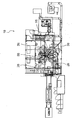
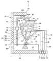
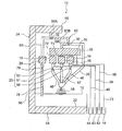
なお、図1~図3では、本発明の一実施形態に係るショット処理装置10の構成が具体的に示されており、図4~図11では、このショット処理装置10の構成が模式的に示されている。
これらの図に示される本発明の一実施形態に係るショット処理装置10は、例えば、ショットブラスト装置として好適に用いられるものである。このショット処理装置10は、キャビネット12と、複数の貯留タンク14~16と、投射ユニット18と、貯留タンク切換部20と、ホッパ22と、搬送部24と、篩26と、補助タンク28と、直結運転切換部の一例である直結運転切換弁30と、排出運転切換部の一例である排出運転切換弁32と、操作部34と、制御部36とを主要な構成として備えている。
図6~図11に示されるように、複数の貯留タンク14~16は、互いに独立して設けられている。この複数の貯留タンク14~16は、互いに異なる粒径区分とされた複数種類のショット材をそれぞれ貯留するためのものである。ここでは、一例として、貯留タンク14には、小粒径のショット材が貯留され、貯留タンク15には、中粒径のショット材が貯留され、貯留タンク16には、大粒径のショット材が貯留される。この複数の貯留タンク14~16には、連結路38~40を介してオーバーフロー受け箱42~44がそれぞれ連結されている。
投射ユニット18は、インペラ式とされており、キャビネット12の上壁部に固定されている。この投射ユニット18は、複数の貯留タンク14~16のそれぞれと投入経路46~48を介して連結されており、複数の貯留タンク14~16のそれぞれから供給されたショット材を投射する構成とされている。なお、投射ユニット18として、エア式のものが用いられても良い。
貯留タンク切換部20は、上述の投入経路46~48のそれぞれに設けられた複数の貯留タンク切換弁50~52を有している。この複数の貯留タンク切換弁50~52は、例えば、電磁式の流量調整弁等とされており、投入経路46~48のそれぞれを開放状態と閉止状態とに切り換える構成とされている。
ホッパ22は、キャビネット12の下部に設けられており、投射ユニット18から投射されたショット材を回収して、後述するコンベヤ54に供給する構成とされている。
搬送部24は、コンベヤ54と、バケットエレベータ56と、セパレータ58とを備えている。コンベヤ54は、ホッパ22から供給されたショット材をバケットエレベータ56に搬送する構成とされており、バケットエレベータ56は、コンベヤ54から供給されたショット材をセパレータ58に搬送する構成とされている。セパレータ58は、ショット材と微粉とに分離し、ショット材のみを後述する還元経路60の上流部60Aに供給する構成とされている。
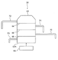
篩26は、セパレータ58と還元経路60を介して連結されている。この篩26は、図4に示されるように、筒体62と、複数の格子64~66と、振動機構68とを有している。複数の格子64~66は、筒体62の内側に収容されると共に、筒体62の軸方向に互いに離間して配置されている。この複数の格子64~66の外周部は、筒体62の内周面とそれぞれ密着されている。なお、このショット処理装置10には、この篩26が複数(一例として4個)備えられている(図3参照)。
第一の格子64は、小粒径及び中粒径のショット材を通過させるが、大粒径のショット材を通過させない大きさの網目を有しており、第二の格子65は、小粒径のショット材を通過させるが、中粒径のショット材を通過させない大きさの網目を有している。また、第三の格子66は、小粒径のショット材よりも小さい微粉を通過させるが、小粒径のショット材を通過させない大きさの網目を有している。
また、筒体62における格子64の上側の部分は、連結路72を介して貯留タンク16と連結されており、筒体62における格子65の上側の部分は、連結路71を介して貯留タンク15と連結されている。また、筒体62における格子66の上側の部分は、連結路70を介して貯留タンク14と連結されており、筒体62における格子66と底部62Aとの間の部分は、連結路73を介して微粉受け箱74と連結されている。振動機構68は、複数の格子64~66でのショット材の選別と、この選別されたショット材及び微粉の連結路70~73への移動を促進するためのものであり、上述の筒体62及び複数の格子64~66の全体に振動を加える構成とされている。
図6~図11に示されるように、セパレータ58と投射ユニット18との間には、投入経路46~48及び還元経路60と並列に直結経路76が設けられている。この直結経路76の上流端は、還元経路60における中間部60Bと下流部60Cとの間に連結されている。
直結運転切換弁30は、この直結経路76と還元経路60との連結部に設けられている。この直結運転切換弁30は、例えば、電磁式の切換弁等とされており、還元経路60の中間部60Bに対して下流部60Cを連通させる状態と、還元経路60の中間部60Bに対して直結経路76を連通させる状態とに切り換えられる構成とされている。
補助タンク28は、上述の複数の貯留タンク14~16と別に設けられている。この補助タンク28とセパレータ58との間には、還元経路60と並列に排出経路80が設けられている。この排出経路80の上流端は、還元経路60における上流部60Aと中間部60Bとの間に連結されている。
排出運転切換弁32は、この排出経路80における還元経路60との連結部に設けられている。この排出運転切換弁32は、例えば、電磁式の切換弁等とされており、還元経路60の上流部60Aに対して中間部60Bを連通させる状態と、還元経路60の上流部60Aに対して排出経路80を連通させる状態とに切り換えられる構成とされている。なお、補助タンク28の下流側には、下流側経路78が連結されており、この下流側経路78には、流量調整弁79が設けられている。
図5に示されるように、操作部34は、操作者が起動操作するための起動操作部82と、操作者が後述する自動切換運転、選択運転、直結運転、排出運転、貯留運転の切換をするための運転切換操作部84と、操作者が自動切換運転において複数種類の供給パターンを選択操作するための供給パターン選択操作部86と、操作者が選択運転において複数の貯留タンク14~16のうち投射ユニット18にショット材を供給する貯留タンクを選択操作するための貯留タンク選択操作部88と、を有している。また、この操作部34は、各操作部が操作された場合には、この操作に応じた信号を出力する構成とされている。
制御部36は、例えば、ECU(Electrical Control Unit)等とされており、上述の投射ユニット18、複数の貯留タンク切換弁50~52、コンベヤ54、バケットエレベータ56、セパレータ58、振動機構68、直結運転切換弁30、排出運転切換弁32、流量調整弁79、操作部34等と電気的に接続されている。そして、この制御部36は、後述するように、操作部34から出力された信号に応じて、複数の貯留タンク切換弁50~52、コンベヤ54、バケットエレベータ56、セパレータ58、振動機構68、直結運転切換弁30、排出運転切換弁32、流量調整弁79等の動作を制御する構成とされている。
また、この制御部36には、記憶部90が備えられており、この記憶部90には、複数の貯留タンク14~16のうち投射ユニット18にショット材を供給する貯留タンクの順番が予め定められた複数種類の供給パターンが記憶されている。この供給パターンには、例えば、貯留タンク14、貯留タンク15、貯留タンク16の順(つまり、小粒径、中粒径、大粒径のショット材の順)に投射ユニット18にショット材を供給するパターンや、貯留タンク16、貯留タンク15、貯留タンク14の順(つまり、大粒径、中粒径、小粒径のショット材の順)に投射ユニット18にショット材を供給するパターン等がある。
次に、上述のショット処理装置10の動作と併せて、その作用及び効果を説明する。
このショット処理装置10では、複数種類のショット材のうち投射されるショット材を自動的に切り換えて複数のショット処理工程を実行する「自動切換運転」と、複数種類のショット材のうちいずれかを選択して使用してショット処理する「選択運転」と、篩26を通さずにセパレータ58から投射ユニット18にショット材を直接供給してショット処理する「直結運転」と、複数の貯留タンク14~16に貯留された複数種類のショット材を補助タンク28に移し変える「排出運転」と、複数の貯留タンク14~16に複数種類のショット材をそれぞれ貯留させる「貯留運転」を行うことができる。以下、この順に説明する。
[自動切換運転]
操作者が運転切換操作部84を操作して自動切換運転を選択すると、操作部34より運転切換信号が制御部36に出力され、制御部36が自動切換運転モードとなる。また、操作者が供給パターン選択操作部86を操作すると、この操作に応じた供給パターン選択信号が操作部34から制御部36に出力される。そして、操作者が起動操作部82を操作すると、起動信号が操作部34から制御部36に出力される。また、制御部36は、起動信号を検出すると、複数の貯留タンク切換弁50~52、コンベヤ54、バケットエレベータ56、セパレータ58、振動機構68、直結運転切換弁30、排出運転切換弁32等を作動させる。
操作者が運転切換操作部84を操作して自動切換運転を選択すると、操作部34より運転切換信号が制御部36に出力され、制御部36が自動切換運転モードとなる。また、操作者が供給パターン選択操作部86を操作すると、この操作に応じた供給パターン選択信号が操作部34から制御部36に出力される。そして、操作者が起動操作部82を操作すると、起動信号が操作部34から制御部36に出力される。また、制御部36は、起動信号を検出すると、複数の貯留タンク切換弁50~52、コンベヤ54、バケットエレベータ56、セパレータ58、振動機構68、直結運転切換弁30、排出運転切換弁32等を作動させる。
ここでは、一例として、供給パターンとして、貯留タンク14、貯留タンク15、貯留タンク16の順(つまり、小粒径、中粒径、大粒径のショット材の順)に投射ユニット18にショット材を供給するパターンが選択された場合について説明する。
自動切換運転では、先ず、図6に示されるように、直結運転切換弁30が還元経路60の中間部60Bに対して下流部60Cを連通させる状態とされると共に、排出運転切換弁32が還元経路60の上流部60Aに対して中間部60Bを連通させる状態とされる。また、貯留タンク切換弁51,52がそれぞれ閉状態に維持され、貯留タンク切換弁50が開状態とされる。
そして、貯留タンク14から小粒径のショット材が投入経路46を通じて投射ユニット18に供給され、投射ユニット18からワークに小粒径のショット材が投射される。
ワークに投射されたショット材は、ホッパ22によって回収されてコンベヤ54に供給され、コンベヤ54に供給されたショット材は、コンベヤ54及びバケットエレベータ56によって搬送されてセパレータ58に供給される。セパレータ58では、ショット材と微粉とに分離され、ショット材のみが還元経路60の上流部60Aに供給される。
そして、還元経路60を流れるショット材は、篩26に供給され、篩26において篩い分けされる。つまり、小粒径のショット材は、図4に示される格子64及び格子65を通過した後、格子66で捕獲される。また、格子66で捕獲された小粒径のショット材は、連結路70を通じて元の貯留タンク14に戻される。
そして、以上の小粒径のショット材によるショット処理工程が一定時間実行されると、図7に示されるように、貯留タンク切換弁50,52がそれぞれ閉状態とされると共に、貯留タンク切換弁51が開状態とされ、次のショット処理工程に移行する。
次のショット処理工程では、貯留タンク15から中粒径のショット材が投入経路47を通じて投射ユニット18に供給され、投射ユニット18からワークに中粒径のショット材が投射される。この中粒径のショット材は、上述の小粒径のショット材の場合と同様に、ホッパ22、コンベヤ54、バケットエレベータ56、セパレータ58、還元経路60を通じて篩26に供給される。
そして、この中粒径のショット材は、篩26において篩い分けされる。つまり、この中粒径のショット材は、図4に示される格子64を通過した後、格子65で捕獲される。また、格子65で捕獲された中粒径のショット材は、連結路71を通じて元の貯留タンク15に戻される。
そして、以上の中粒径のショット材によるショット処理工程が一定時間実行されると、図8に示されるように、貯留タンク切換弁50,51がそれぞれ閉状態とされると共に、貯留タンク切換弁52が開状態とされ、次のショット処理工程に移行する。
次のショット処理工程では、貯留タンク16から大粒径のショット材が投入経路48を通じて投射ユニット18に供給され、投射ユニット18からワークに大粒径のショット材が投射される。この大粒径のショット材は、上述の小粒径、中粒径のショット材の場合と同様に、ホッパ22、コンベヤ54、バケットエレベータ56、セパレータ58、還元経路60を通じて篩26に供給される。
そして、この大粒径のショット材は、篩26において篩い分けされる。つまり、この大粒径のショット材は、図4に示される格子64で捕獲される。また、この格子64で捕獲された大粒径のショット材は、連結路72を通じて元の貯留タンク16に戻される。
そして、以上の大粒径のショット材によるショット処理工程が一定時間実行されると、制御部36が、コンベヤ54、バケットエレベータ56、セパレータ58、振動機構68の動作を停止させる。
なお、その他の供給パターンとして、例えば、貯留タンク16、貯留タンク15、貯留タンク14の順(つまり、大粒径、中粒径、小粒径のショット材の順)に投射ユニット18にショット材を供給するパターンが選択された場合も、投射ユニット18にショット材を供給する順番が異なるだけで基本的な動作は上記と同様である。
このように、このショット処理装置10によれば、貯留タンク切換部20によって複数の貯留タンク14~16のうち投射ユニット18にショット材を供給する貯留タンクが順に切り換えられることにより、複数種類のショット材を順に用いた複数のショット処理工程を実行することができる。従って、ショット材の粒径を変えてワークをショット処理する場合でも、ショット処理装置10からショット材の抜き換えを行う必要が無く、また、ショット材の粒径毎にショット処理装置を用意する必要も無いので、コストを抑えつつ、作業効率を向上させることができる。
また、自動切換運転では、操作者が起動操作部82を起動操作するだけで、複数種類のショット材を順に用いた複数のショット処理工程を自動的に実行することができる。これにより、作業効率をより向上させることができる。
また、自動切換運転では、操作者が供給パターン選択操作部86を選択操作することにより、複数種類のショット材のうち投射されるショット材の順番を変更することができる。これにより、ショット処理装置10の使い勝手を向上させることができる。
[選択運転]
操作者が運転切換操作部84を操作して選択運転を選択すると、操作部34より運転切換信号が制御部36に出力され、制御部36が選択運転モードとなる。また、操作者が貯留タンク選択操作部88を操作すると、この操作に応じた貯留タンク選択信号が操作部34から制御部36に出力される。そして、操作者が起動操作部82を操作すると、起動信号が操作部34から制御部36に出力される。また、制御部36は、起動信号を検出すると、複数の貯留タンク切換弁50~52、コンベヤ54、バケットエレベータ56、セパレータ58、振動機構68、直結運転切換弁30、排出運転切換弁32等を作動させる。
操作者が運転切換操作部84を操作して選択運転を選択すると、操作部34より運転切換信号が制御部36に出力され、制御部36が選択運転モードとなる。また、操作者が貯留タンク選択操作部88を操作すると、この操作に応じた貯留タンク選択信号が操作部34から制御部36に出力される。そして、操作者が起動操作部82を操作すると、起動信号が操作部34から制御部36に出力される。また、制御部36は、起動信号を検出すると、複数の貯留タンク切換弁50~52、コンベヤ54、バケットエレベータ56、セパレータ58、振動機構68、直結運転切換弁30、排出運転切換弁32等を作動させる。
ここでは、一例として、複数の貯留タンク14~16のうち小粒径のショット材を貯留する貯留タンク14が選択された場合について説明する。
選択運転では、先ず、図6に示されるように、直結運転切換弁30が還元経路60の中間部60Bに対して下流部60Cを連通させる状態とされると共に、排出運転切換弁32が還元経路60の上流部60Aに対して中間部60Bを連通させる状態とされる。また、貯留タンク切換弁51,52がそれぞれ閉状態に維持され、貯留タンク切換弁50が開状態とされる。
そして、貯留タンク14から小粒径のショット材が投入経路46を通じて投射ユニット18に供給され、投射ユニット18からワークに小粒径のショット材が投射される。ワークに投射されたショット材が元の貯留タンク14に戻るまでの経路は、上述の自動切換運転の場合と同様である。
そして、以上のショット処理が一定の時間経過すると、制御部36が、コンベヤ54、バケットエレベータ56、セパレータ58、振動機構68の動作を停止させる。
なお、複数の貯留タンク14~16のうち中粒径のショット材を貯留する貯留タンク15が選択された場合、大粒径のショット材を貯留する貯留タンク16が選択された場合も、複数の貯留タンク切換弁50~52の動作が異なるだけで基本的な動作は上記と同様である(図7,図8参照)。
このように、この選択運転では、操作者が貯留タンク選択操作部88を選択操作することにより、複数種類のショット材のうちいずれかを選択して使用することができる。これにより、ショット処理装置10の使い勝手を向上させることができる。
[直結運転]
操作者が運転切換操作部84を操作して直結運転を選択すると、操作部34より運転切換信号が制御部36に出力され、制御部36が直結運転モードとなる。そして、操作者が起動操作部82を操作すると、起動信号が操作部34から制御部36に出力される。また、制御部36は、起動信号を検出すると、複数の貯留タンク切換弁50~52、コンベヤ54、バケットエレベータ56、セパレータ58、振動機構68、直結運転切換弁30、排出運転切換弁32等を作動させる。
操作者が運転切換操作部84を操作して直結運転を選択すると、操作部34より運転切換信号が制御部36に出力され、制御部36が直結運転モードとなる。そして、操作者が起動操作部82を操作すると、起動信号が操作部34から制御部36に出力される。また、制御部36は、起動信号を検出すると、複数の貯留タンク切換弁50~52、コンベヤ54、バケットエレベータ56、セパレータ58、振動機構68、直結運転切換弁30、排出運転切換弁32等を作動させる。
直結運転では、先ず、図9に示されるように、直結運転切換弁30が還元経路60の中間部60Bに対して直結経路76を連通させる状態とされると共に、排出運転切換弁32が還元経路60の上流部60Aに対して中間部60Bを連通させる状態とされる。
なお、この直結運転では、複数の貯留タンク14~16に貯留された小粒径のショット材、中粒径のショット、大粒径のショット材のいずれかを選択して使用することも可能であるが、複数の貯留タンク14~16に貯留された小粒径、中粒径、大粒径のショット材の全てを混合して使用することも可能である。
そして、直結経路76を通じてセパレータ58から投射ユニット18にショット材が直接供給され、投射ユニット18からワークにショット材が投射される。ワークに投射されたショット材がセパレータ58に戻るまでの経路は、上述の自動切換運転及び選択運転の場合と同様である。
このように、この直結運転では、篩26を通さずに搬送部24から投射ユニット18にショット材を直接供給してショット処理することができる。従って、これにより、例えば、複数の貯留タンク14~16に貯留された複数種類のショット材を混合させた状態で使用してショット処理することができる。
[排出運転]
操作者が運転切換操作部84を操作して排出運転を選択すると、操作部34より運転切換信号が制御部36に出力され、制御部36が排出運転モードとなる。そして、操作者が起動操作部82を操作すると、起動信号が操作部34から制御部36に出力される。また、制御部36は、起動信号を検出すると、複数の貯留タンク切換弁50~52、コンベヤ54、バケットエレベータ56、セパレータ58、振動機構68、直結運転切換弁30、排出運転切換弁32、流量調整弁79等を作動させる。
操作者が運転切換操作部84を操作して排出運転を選択すると、操作部34より運転切換信号が制御部36に出力され、制御部36が排出運転モードとなる。そして、操作者が起動操作部82を操作すると、起動信号が操作部34から制御部36に出力される。また、制御部36は、起動信号を検出すると、複数の貯留タンク切換弁50~52、コンベヤ54、バケットエレベータ56、セパレータ58、振動機構68、直結運転切換弁30、排出運転切換弁32、流量調整弁79等を作動させる。
ここでは、一例として、貯留タンク14に貯留された小粒径のショット材を補助タンク28に移し変える場合について説明する。
排出運転では、先ず、図10に示されるように、排出運転切換弁32が還元経路60の上流部60Aに対して排出経路80を連通させる状態とされる。また、貯留タンク切換弁51,52がそれぞれ閉状態に維持され、貯留タンク切換弁50が開状態とされる。また、流量調整弁79が閉状態とされる。
そして、貯留タンク14から小粒径のショット材が投入経路46を通じて投射ユニット18に供給され、投射ユニット18からホッパ22に小粒径のショット材が投射される。
ホッパ22に投射されたショット材は、コンベヤ54に供給され、コンベヤ54及びバケットエレベータ56によってセパレータ58に搬送される。セパレータ58では、ショット材と微粉とに分離され、ショット材のみが還元経路60の上流部60Aに供給される。
そして、還元経路60の上流部60A及び排出経路80を通じてセパレータ58から補助タンク28にショット材が供給され、一定時間経過すると、貯留タンク14のショット材が全て補助タンク28に移し変えられる。
なお、中粒径のショット材、大粒径のショット材を補助タンク28に移し変える場合も、複数の貯留タンク切換弁50~52の動作が異なるだけで基本的な動作は上記と同様である。また、小粒径のショット材、中粒径のショット、大粒径のショット材の全てを補助タンク28に移し変えることも可能である。
このように、この排出運転では、複数の貯留タンク14~16に貯留された複数種類のショット材を補助タンク28に移し変えることができる。これにより、例えば、複数の貯留タンク14~16のメンテナンスや、ショット材の抜き換え時の作業性を向上させることができる。
[貯留運転]
操作者が運転切換操作部84を操作して貯留運転を選択すると、操作部34より運転切換信号が制御部36に出力され、制御部36が貯留運転モードとなる。そして、操作者が起動操作部82を操作すると、起動信号が操作部34から制御部36に出力される。また、制御部36は、起動信号を検出すると、複数の貯留タンク切換弁50~52、コンベヤ54、バケットエレベータ56、セパレータ58、振動機構68、直結運転切換弁30、排出運転切換弁32、流量調整弁79等を作動させる。
操作者が運転切換操作部84を操作して貯留運転を選択すると、操作部34より運転切換信号が制御部36に出力され、制御部36が貯留運転モードとなる。そして、操作者が起動操作部82を操作すると、起動信号が操作部34から制御部36に出力される。また、制御部36は、起動信号を検出すると、複数の貯留タンク切換弁50~52、コンベヤ54、バケットエレベータ56、セパレータ58、振動機構68、直結運転切換弁30、排出運転切換弁32、流量調整弁79等を作動させる。
なお、貯留運転は、複数の貯留タンク14~16のそれぞれにショット材を貯留させるための運転であり、複数の貯留タンク14~16が空の状態で開始される。また、複数種類のショット材については、ホッパ22に混合させた状態で投入することも可能であるが、ここでは、一例として補助タンク28に投入した場合について説明する。
貯留運転では、先ず、図11に示されるように、直結運転切換弁30が還元経路60の中間部60Bに対して下流部60Cを連通させる状態とされると共に、排出運転切換弁32が還元経路60の上流部60Aに対して中間部60Bを連通させる状態とされる。また、複数の貯留タンク切換弁50~52は、それぞれ閉状態とされ、流量調整弁79は、開状態とされる。
そして、補助タンク28に投入されたショット材は、下流側経路78及びホッパ22を通じてコンベヤ54に供給され、コンベヤ54及びバケットエレベータ56によってセパレータ58に搬送される。セパレータ58では、ショット材と微粉とに分離され、ショット材のみが還元経路60に供給される。
そして、還元経路60を流れるショット材は、篩26に供給され、篩26において篩い分けされる。この篩26における篩い分けは、上述の自動切換運転等の場合と同様である。そして、篩26において篩い分けされることにより、小粒径、中粒径、大粒径のショット材は、それぞれ複数の貯留タンク14~16に貯留される。
このように、この貯留運転では、複数種類のショット材を補助タンク28やホッパ22に混合させた状態で投入するだけで、複数の貯留タンク14~16に複数種類のショット材をそれぞれ貯留させることができる。これにより、ショット処理装置10の使い勝手を向上させることができる。
なお、このショット処理装置は、ショットブラスト装置の他に、ショットピーニング装置としても使用可能である。
以上、本発明の一実施形態について説明したが、本発明は、上記に限定されるものでなく、上記以外にも、その主旨を逸脱しない範囲内において種々変形して実施可能であることは勿論である。
Claims (6)
- 互いに異なる粒径区分とされた複数種類のショット材をそれぞれ貯留するための複数の貯留タンクと、
前記複数の貯留タンクのそれぞれから供給されたショット材を投射する投射ユニットと、
前記複数の貯留タンクと前記投射ユニットとを連結する投入経路に設けられ、前記複数の貯留タンクのうち前記投射ユニットにショット材を供給する貯留タンクを切り換える貯留タンク切換部と、
前記投射ユニットから投射されたショット材を搬送する搬送部と、
前記搬送部と還元経路を介して連結され、前記搬送部により搬送されたショット材を粒径区分に基づいて篩い分けて前記複数の貯留タンクのうち元の貯留タンクに戻す篩と、
を備えたショット処理装置。
- 操作者が起動操作するための起動操作部を有すると共に、前記起動操作部が起動操作された場合に起動信号を出力する操作部と、
前記起動信号を検出した場合に、前記投射ユニット及び前記搬送部を作動させると共に、前記複数の貯留タンクのうち前記投射ユニットにショット材を供給する貯留タンクがショット処理工程毎に切り換えられるように前記貯留タンク切換部の切換状態を制御して、前記複数種類のショット材を順に用いた複数のショット処理工程を実行させる制御部と、
を備えた請求項1に記載のショット処理装置。
- 前記複数の貯留タンクのうち前記投射ユニットにショット材を供給する貯留タンクの順番が予め定められた複数種類の供給パターンを記憶した記憶部を備え、
前記操作部は、操作者が前記複数種類の供給パターンを選択操作するための供給パターン選択操作部を有すると共に、前記供給パターン選択操作部の選択操作に応じた供給パターン選択信号を出力し、
前記制御部は、前記供給パターン選択信号に対応する順番で前記複数の貯留タンクから前記投射ユニットにショット材が供給されるように、前記貯留タンク切換部の切換状態を制御する、
請求項2に記載のショット処理装置。
- 前記操作部は、操作者が前記複数の貯留タンクのうち前記投射ユニットにショット材を供給する貯留タンクを選択操作するための貯留タンク選択操作部を有すると共に、前記貯留タンク選択操作部の選択操作に応じた貯留タンク選択信号を出力し、
前記制御部は、前記複数の貯留タンクのうち前記貯留タンク選択信号に対応する貯留タンクから前記投射ユニットにショット材が供給されるように、前記貯留タンク切換部の切換状態を制御する、
請求項2又は請求項3に記載のショット処理装置。
- 前記搬送部と前記投射ユニットとの間に前記投入経路及び前記還元経路と並列に設けられた直結経路と、
前記還元経路を通じて前記搬送部から前記篩にショット材が流れる状態と、前記直結経路を通じて前記搬送部から前記投射ユニットにショット材が流れる状態とに切り換える直結運転切換部と、
を備えた請求項1~請求項3のいずれか一項に記載のショット処理装置。
- 前記複数の貯留タンクと別に設けられた補助タンクと、
前記搬送部と前記補助タンクとの間に前記還元経路と並列に設けられた排出経路と、
前記還元経路を通じて前記搬送部から前記投射ユニットにショット材が流れる状態と、前記排出経路を通じて前記搬送部から前記補助タンクにショット材が流れる状態とに切り換える排出運転切換部と、
を備えた請求項1~請求項3のいずれか一項に記載のショット処理装置。
Priority Applications (1)
| Application Number | Priority Date | Filing Date | Title |
|---|---|---|---|
| CN201180037492.6A CN103038024B (zh) | 2010-12-24 | 2011-07-22 | 喷丸处理装置 |
Applications Claiming Priority (2)
| Application Number | Priority Date | Filing Date | Title |
|---|---|---|---|
| JP2010288943A JP2014039961A (ja) | 2010-12-24 | 2010-12-24 | ショット処理装置 |
| JP2010-288943 | 2010-12-24 |
Publications (1)
| Publication Number | Publication Date |
|---|---|
| WO2012086249A1 true WO2012086249A1 (ja) | 2012-06-28 |
Family
ID=46313536
Family Applications (1)
| Application Number | Title | Priority Date | Filing Date |
|---|---|---|---|
| PCT/JP2011/066719 Ceased WO2012086249A1 (ja) | 2010-12-24 | 2011-07-22 | ショット処理装置 |
Country Status (3)
| Country | Link |
|---|---|
| JP (1) | JP2014039961A (ja) |
| CN (1) | CN103038024B (ja) |
| WO (1) | WO2012086249A1 (ja) |
Families Citing this family (4)
| Publication number | Priority date | Publication date | Assignee | Title |
|---|---|---|---|---|
| CN103522201B (zh) * | 2013-10-18 | 2015-09-30 | 山东开泰工业科技有限公司 | 一种发动机叶片抛丸强化装置及强化方法 |
| JP5820524B1 (ja) * | 2014-12-11 | 2015-11-24 | キム キョンジョ | ショット成形装置 |
| CN107877387A (zh) * | 2017-11-30 | 2018-04-06 | 无锡市日升机械厂 | 可旋转的双通道式喷砂机 |
| CN118123718A (zh) * | 2024-01-27 | 2024-06-04 | 江苏宏大特种钢机械厂有限公司 | 双层表面渗处理喷丸喷涂系统及其应用方法 |
Citations (3)
| Publication number | Priority date | Publication date | Assignee | Title |
|---|---|---|---|---|
| JPH05318317A (ja) * | 1992-05-13 | 1993-12-03 | Aberu Kk | ショットブラストによる金属の着色方法 |
| JPH06246636A (ja) * | 1993-02-26 | 1994-09-06 | Eikichi Yamaharu | ブラスト装置およびこれを利用した金型仕上げ装置 |
| JP2005262349A (ja) * | 2004-03-17 | 2005-09-29 | Jfe Steel Kk | 表面テクスチャー付金属板の製造装置及び製造方法 |
Family Cites Families (7)
| Publication number | Priority date | Publication date | Assignee | Title |
|---|---|---|---|---|
| NL8603134A (nl) * | 1986-12-09 | 1988-07-01 | Ltc Int Bv | Straalschuurinrichting. |
| JP2684292B2 (ja) * | 1992-03-10 | 1997-12-03 | 株式会社不二精機製造所 | 研削砥石のドレッシング方法及び装置 |
| JP2006043793A (ja) * | 2004-08-02 | 2006-02-16 | Bridgestone Corp | ブラスト装置およびブラスト処理方法 |
| CN100509290C (zh) * | 2007-09-24 | 2009-07-08 | 无锡国达机械设备有限公司 | 汽车齿轮强化抛丸机 |
| JP5057236B2 (ja) * | 2008-04-23 | 2012-10-24 | 新東工業株式会社 | ショットブラスト処理装置 |
| CN201632936U (zh) * | 2009-05-26 | 2010-11-17 | 上海大学 | 磨料浆体射流微孔喷嘴内流道加工设备 |
| CN101633154B (zh) * | 2009-08-05 | 2011-05-18 | 长沙矿冶研究院 | 在线高压水射流喷砂表面清理系统 |
-
2010
- 2010-12-24 JP JP2010288943A patent/JP2014039961A/ja active Pending
-
2011
- 2011-07-22 WO PCT/JP2011/066719 patent/WO2012086249A1/ja not_active Ceased
- 2011-07-22 CN CN201180037492.6A patent/CN103038024B/zh active Active
Patent Citations (3)
| Publication number | Priority date | Publication date | Assignee | Title |
|---|---|---|---|---|
| JPH05318317A (ja) * | 1992-05-13 | 1993-12-03 | Aberu Kk | ショットブラストによる金属の着色方法 |
| JPH06246636A (ja) * | 1993-02-26 | 1994-09-06 | Eikichi Yamaharu | ブラスト装置およびこれを利用した金型仕上げ装置 |
| JP2005262349A (ja) * | 2004-03-17 | 2005-09-29 | Jfe Steel Kk | 表面テクスチャー付金属板の製造装置及び製造方法 |
Also Published As
| Publication number | Publication date |
|---|---|
| JP2014039961A (ja) | 2014-03-06 |
| CN103038024B (zh) | 2015-12-16 |
| CN103038024A (zh) | 2013-04-10 |
Similar Documents
| Publication | Publication Date | Title |
|---|---|---|
| WO2012086249A1 (ja) | ショット処理装置 | |
| US20100071616A1 (en) | Coating powder filter device | |
| JP6875980B2 (ja) | 回転ドラムを備えた篩機 | |
| US7971551B2 (en) | Powder spray coating apparatus and powder spray coating method | |
| CN101823059B (zh) | 红土矿洗矿设备 | |
| WO2017154390A1 (ja) | 圧電式バルブ、該圧電式バルブの駆動方法、及び該圧電式バルブを利用した噴風手段を備える光学式粒状物選別機 | |
| JP2008018476A (ja) | ショット処理装置 | |
| TW200936221A (en) | Bag-filter type small deodorizing and dust collecting apparatus | |
| CN102847678A (zh) | 一种多级组合式烟丝振动筛分装置 | |
| JP2006111434A (ja) | フィーダー及び色彩選別機 | |
| CN114653454A (zh) | 建筑废弃物回收—体化系统 | |
| CN202290588U (zh) | 干法排煤矸石选煤的系统 | |
| US7232360B2 (en) | Uninterrupted abrasive fluid supply | |
| CN201320530Y (zh) | 一种氯化聚乙烯专用直线筛 | |
| CN204247516U (zh) | 一种石英粉振动筛分装置 | |
| JP6896227B2 (ja) | 石抜機 | |
| JP2012240696A (ja) | 粉粒体運搬車 | |
| JP2012250144A (ja) | 粒選別機の搬送装置 | |
| KR200324496Y1 (ko) | 비산방지 이송시스템 | |
| JPS6054278A (ja) | 溶接フラツクス循環使用方法 | |
| JP2011144040A (ja) | 粒体の空気輸送装置 | |
| JP7589399B2 (ja) | 異物除去装置、石膏系建築用面材製造装置、異物除去方法 | |
| JP4041565B2 (ja) | 気力輸送装置 | |
| JP2015093233A (ja) | 連続運転を可能にする微粉捕集用バッグフィルター | |
| EP1637283A1 (en) | Turbine blasting machine |
Legal Events
| Date | Code | Title | Description |
|---|---|---|---|
| WWE | Wipo information: entry into national phase |
Ref document number: 201180037492.6 Country of ref document: CN |
|
| 121 | Ep: the epo has been informed by wipo that ep was designated in this application |
Ref document number: 11850021 Country of ref document: EP Kind code of ref document: A1 |
|
| NENP | Non-entry into the national phase |
Ref country code: DE |
|
| NENP | Non-entry into the national phase |
Ref country code: JP |
|
| 122 | Ep: pct application non-entry in european phase |
Ref document number: 11850021 Country of ref document: EP Kind code of ref document: A1 |