WO2012081460A1 - Dpfシステム - Google Patents
Dpfシステム Download PDFInfo
- Publication number
- WO2012081460A1 WO2012081460A1 PCT/JP2011/078280 JP2011078280W WO2012081460A1 WO 2012081460 A1 WO2012081460 A1 WO 2012081460A1 JP 2011078280 W JP2011078280 W JP 2011078280W WO 2012081460 A1 WO2012081460 A1 WO 2012081460A1
- Authority
- WO
- WIPO (PCT)
- Prior art keywords
- doc
- amount
- heat generation
- value
- injection amount
- Prior art date
- Legal status (The legal status is an assumption and is not a legal conclusion. Google has not performed a legal analysis and makes no representation as to the accuracy of the status listed.)
- Ceased
Links
Images



Classifications
-
- F—MECHANICAL ENGINEERING; LIGHTING; HEATING; WEAPONS; BLASTING
- F01—MACHINES OR ENGINES IN GENERAL; ENGINE PLANTS IN GENERAL; STEAM ENGINES
- F01N—GAS-FLOW SILENCERS OR EXHAUST APPARATUS FOR MACHINES OR ENGINES IN GENERAL; GAS-FLOW SILENCERS OR EXHAUST APPARATUS FOR INTERNAL-COMBUSTION ENGINES
- F01N3/00—Exhaust or silencing apparatus having means for purifying, rendering innocuous, or otherwise treating exhaust
- F01N3/02—Exhaust or silencing apparatus having means for purifying, rendering innocuous, or otherwise treating exhaust for cooling, or for removing solid constituents of, exhaust
- F01N3/021—Exhaust or silencing apparatus having means for purifying, rendering innocuous, or otherwise treating exhaust for cooling, or for removing solid constituents of, exhaust by means of filters
- F01N3/023—Exhaust or silencing apparatus having means for purifying, rendering innocuous, or otherwise treating exhaust for cooling, or for removing solid constituents of, exhaust by means of filters using means for regenerating the filters, e.g. by burning trapped particles
- F01N3/025—Exhaust or silencing apparatus having means for purifying, rendering innocuous, or otherwise treating exhaust for cooling, or for removing solid constituents of, exhaust by means of filters using means for regenerating the filters, e.g. by burning trapped particles using fuel burner or by adding fuel to exhaust
- F01N3/0253—Exhaust or silencing apparatus having means for purifying, rendering innocuous, or otherwise treating exhaust for cooling, or for removing solid constituents of, exhaust by means of filters using means for regenerating the filters, e.g. by burning trapped particles using fuel burner or by adding fuel to exhaust adding fuel to exhaust gases
-
- F—MECHANICAL ENGINEERING; LIGHTING; HEATING; WEAPONS; BLASTING
- F01—MACHINES OR ENGINES IN GENERAL; ENGINE PLANTS IN GENERAL; STEAM ENGINES
- F01N—GAS-FLOW SILENCERS OR EXHAUST APPARATUS FOR MACHINES OR ENGINES IN GENERAL; GAS-FLOW SILENCERS OR EXHAUST APPARATUS FOR INTERNAL-COMBUSTION ENGINES
- F01N11/00—Monitoring or diagnostic devices for exhaust-gas treatment apparatus
- F01N11/002—Monitoring or diagnostic devices for exhaust-gas treatment apparatus the diagnostic devices measuring or estimating temperature or pressure in, or downstream of the exhaust apparatus
-
- F—MECHANICAL ENGINEERING; LIGHTING; HEATING; WEAPONS; BLASTING
- F01—MACHINES OR ENGINES IN GENERAL; ENGINE PLANTS IN GENERAL; STEAM ENGINES
- F01N—GAS-FLOW SILENCERS OR EXHAUST APPARATUS FOR MACHINES OR ENGINES IN GENERAL; GAS-FLOW SILENCERS OR EXHAUST APPARATUS FOR INTERNAL-COMBUSTION ENGINES
- F01N13/00—Exhaust or silencing apparatus characterised by constructional features
- F01N13/009—Exhaust or silencing apparatus characterised by constructional features having two or more separate purifying devices arranged in series
-
- F—MECHANICAL ENGINEERING; LIGHTING; HEATING; WEAPONS; BLASTING
- F01—MACHINES OR ENGINES IN GENERAL; ENGINE PLANTS IN GENERAL; STEAM ENGINES
- F01N—GAS-FLOW SILENCERS OR EXHAUST APPARATUS FOR MACHINES OR ENGINES IN GENERAL; GAS-FLOW SILENCERS OR EXHAUST APPARATUS FOR INTERNAL-COMBUSTION ENGINES
- F01N13/00—Exhaust or silencing apparatus characterised by constructional features
- F01N13/009—Exhaust or silencing apparatus characterised by constructional features having two or more separate purifying devices arranged in series
- F01N13/0093—Exhaust or silencing apparatus characterised by constructional features having two or more separate purifying devices arranged in series the purifying devices are of the same type
-
- F—MECHANICAL ENGINEERING; LIGHTING; HEATING; WEAPONS; BLASTING
- F01—MACHINES OR ENGINES IN GENERAL; ENGINE PLANTS IN GENERAL; STEAM ENGINES
- F01N—GAS-FLOW SILENCERS OR EXHAUST APPARATUS FOR MACHINES OR ENGINES IN GENERAL; GAS-FLOW SILENCERS OR EXHAUST APPARATUS FOR INTERNAL-COMBUSTION ENGINES
- F01N13/00—Exhaust or silencing apparatus characterised by constructional features
- F01N13/009—Exhaust or silencing apparatus characterised by constructional features having two or more separate purifying devices arranged in series
- F01N13/0097—Exhaust or silencing apparatus characterised by constructional features having two or more separate purifying devices arranged in series the purifying devices are arranged in a single housing
-
- F—MECHANICAL ENGINEERING; LIGHTING; HEATING; WEAPONS; BLASTING
- F01—MACHINES OR ENGINES IN GENERAL; ENGINE PLANTS IN GENERAL; STEAM ENGINES
- F01N—GAS-FLOW SILENCERS OR EXHAUST APPARATUS FOR MACHINES OR ENGINES IN GENERAL; GAS-FLOW SILENCERS OR EXHAUST APPARATUS FOR INTERNAL-COMBUSTION ENGINES
- F01N3/00—Exhaust or silencing apparatus having means for purifying, rendering innocuous, or otherwise treating exhaust
- F01N3/08—Exhaust or silencing apparatus having means for purifying, rendering innocuous, or otherwise treating exhaust for rendering innocuous
- F01N3/10—Exhaust or silencing apparatus having means for purifying, rendering innocuous, or otherwise treating exhaust for rendering innocuous by thermal or catalytic conversion of noxious components of exhaust
- F01N3/103—Oxidation catalysts for HC and CO only
-
- F—MECHANICAL ENGINEERING; LIGHTING; HEATING; WEAPONS; BLASTING
- F01—MACHINES OR ENGINES IN GENERAL; ENGINE PLANTS IN GENERAL; STEAM ENGINES
- F01N—GAS-FLOW SILENCERS OR EXHAUST APPARATUS FOR MACHINES OR ENGINES IN GENERAL; GAS-FLOW SILENCERS OR EXHAUST APPARATUS FOR INTERNAL-COMBUSTION ENGINES
- F01N3/00—Exhaust or silencing apparatus having means for purifying, rendering innocuous, or otherwise treating exhaust
- F01N3/08—Exhaust or silencing apparatus having means for purifying, rendering innocuous, or otherwise treating exhaust for rendering innocuous
- F01N3/10—Exhaust or silencing apparatus having means for purifying, rendering innocuous, or otherwise treating exhaust for rendering innocuous by thermal or catalytic conversion of noxious components of exhaust
- F01N3/18—Exhaust or silencing apparatus having means for purifying, rendering innocuous, or otherwise treating exhaust for rendering innocuous by thermal or catalytic conversion of noxious components of exhaust characterised by methods of operation; Control
- F01N3/20—Exhaust or silencing apparatus having means for purifying, rendering innocuous, or otherwise treating exhaust for rendering innocuous by thermal or catalytic conversion of noxious components of exhaust characterised by methods of operation; Control specially adapted for catalytic conversion
- F01N3/2006—Periodically heating or cooling catalytic reactors, e.g. at cold starting or overheating
- F01N3/2033—Periodically heating or cooling catalytic reactors, e.g. at cold starting or overheating using a fuel burner or introducing fuel into exhaust duct
-
- F—MECHANICAL ENGINEERING; LIGHTING; HEATING; WEAPONS; BLASTING
- F01—MACHINES OR ENGINES IN GENERAL; ENGINE PLANTS IN GENERAL; STEAM ENGINES
- F01N—GAS-FLOW SILENCERS OR EXHAUST APPARATUS FOR MACHINES OR ENGINES IN GENERAL; GAS-FLOW SILENCERS OR EXHAUST APPARATUS FOR INTERNAL-COMBUSTION ENGINES
- F01N13/00—Exhaust or silencing apparatus characterised by constructional features
- F01N13/008—Mounting or arrangement of exhaust sensors in or on exhaust apparatus
-
- F—MECHANICAL ENGINEERING; LIGHTING; HEATING; WEAPONS; BLASTING
- F01—MACHINES OR ENGINES IN GENERAL; ENGINE PLANTS IN GENERAL; STEAM ENGINES
- F01N—GAS-FLOW SILENCERS OR EXHAUST APPARATUS FOR MACHINES OR ENGINES IN GENERAL; GAS-FLOW SILENCERS OR EXHAUST APPARATUS FOR INTERNAL-COMBUSTION ENGINES
- F01N2550/00—Monitoring or diagnosing the deterioration of exhaust systems
-
- F—MECHANICAL ENGINEERING; LIGHTING; HEATING; WEAPONS; BLASTING
- F01—MACHINES OR ENGINES IN GENERAL; ENGINE PLANTS IN GENERAL; STEAM ENGINES
- F01N—GAS-FLOW SILENCERS OR EXHAUST APPARATUS FOR MACHINES OR ENGINES IN GENERAL; GAS-FLOW SILENCERS OR EXHAUST APPARATUS FOR INTERNAL-COMBUSTION ENGINES
- F01N2560/00—Exhaust systems with means for detecting or measuring exhaust gas components or characteristics
- F01N2560/06—Exhaust systems with means for detecting or measuring exhaust gas components or characteristics the means being a temperature sensor
-
- F—MECHANICAL ENGINEERING; LIGHTING; HEATING; WEAPONS; BLASTING
- F01—MACHINES OR ENGINES IN GENERAL; ENGINE PLANTS IN GENERAL; STEAM ENGINES
- F01N—GAS-FLOW SILENCERS OR EXHAUST APPARATUS FOR MACHINES OR ENGINES IN GENERAL; GAS-FLOW SILENCERS OR EXHAUST APPARATUS FOR INTERNAL-COMBUSTION ENGINES
- F01N2560/00—Exhaust systems with means for detecting or measuring exhaust gas components or characteristics
- F01N2560/14—Exhaust systems with means for detecting or measuring exhaust gas components or characteristics having more than one sensor of one kind
-
- F—MECHANICAL ENGINEERING; LIGHTING; HEATING; WEAPONS; BLASTING
- F01—MACHINES OR ENGINES IN GENERAL; ENGINE PLANTS IN GENERAL; STEAM ENGINES
- F01N—GAS-FLOW SILENCERS OR EXHAUST APPARATUS FOR MACHINES OR ENGINES IN GENERAL; GAS-FLOW SILENCERS OR EXHAUST APPARATUS FOR INTERNAL-COMBUSTION ENGINES
- F01N3/00—Exhaust or silencing apparatus having means for purifying, rendering innocuous, or otherwise treating exhaust
- F01N3/08—Exhaust or silencing apparatus having means for purifying, rendering innocuous, or otherwise treating exhaust for rendering innocuous
- F01N3/0807—Exhaust or silencing apparatus having means for purifying, rendering innocuous, or otherwise treating exhaust for rendering innocuous by using absorbents or adsorbents
- F01N3/0828—Exhaust or silencing apparatus having means for purifying, rendering innocuous, or otherwise treating exhaust for rendering innocuous by using absorbents or adsorbents characterised by the absorbed or adsorbed substances
- F01N3/0835—Hydrocarbons
-
- Y—GENERAL TAGGING OF NEW TECHNOLOGICAL DEVELOPMENTS; GENERAL TAGGING OF CROSS-SECTIONAL TECHNOLOGIES SPANNING OVER SEVERAL SECTIONS OF THE IPC; TECHNICAL SUBJECTS COVERED BY FORMER USPC CROSS-REFERENCE ART COLLECTIONS [XRACs] AND DIGESTS
- Y02—TECHNOLOGIES OR APPLICATIONS FOR MITIGATION OR ADAPTATION AGAINST CLIMATE CHANGE
- Y02T—CLIMATE CHANGE MITIGATION TECHNOLOGIES RELATED TO TRANSPORTATION
- Y02T10/00—Road transport of goods or passengers
- Y02T10/10—Internal combustion engine [ICE] based vehicles
- Y02T10/12—Improving ICE efficiencies
-
- Y—GENERAL TAGGING OF NEW TECHNOLOGICAL DEVELOPMENTS; GENERAL TAGGING OF CROSS-SECTIONAL TECHNOLOGIES SPANNING OVER SEVERAL SECTIONS OF THE IPC; TECHNICAL SUBJECTS COVERED BY FORMER USPC CROSS-REFERENCE ART COLLECTIONS [XRACs] AND DIGESTS
- Y02—TECHNOLOGIES OR APPLICATIONS FOR MITIGATION OR ADAPTATION AGAINST CLIMATE CHANGE
- Y02T—CLIMATE CHANGE MITIGATION TECHNOLOGIES RELATED TO TRANSPORTATION
- Y02T10/00—Road transport of goods or passengers
- Y02T10/10—Internal combustion engine [ICE] based vehicles
- Y02T10/40—Engine management systems
Definitions
- the present invention relates to a DPF system that collects particulate matter from exhaust gas of a diesel engine with DPF and burns and removes it by exhaust pipe injection.
- DPF Diesel Particulate Filter
- PM Pulse Matter
- Patent Document 1 a filter called DPF is connected to the exhaust pipe to collect PM from the exhaust gas, and NO x in the exhaust gas is converted to NO 2 by a DOC (Diesel Oxidation Catalyst) provided upstream of the DPF. Then, PM is oxidized (combusted) by the oxidizing power of NO 2 to remove PM.
- DOC Diesel Oxidation Catalyst
- Post-injection can be carried out with the configuration of the conventional engine system, but there are problems such as oil dilution in the engine cylinder, smoke emission of exhaust gas, and influence on operability.
- DPF regeneration can be performed by raising the temperature of the exhaust gas without causing the above-described problems.
- FIG. 5 is a diagram showing the relationship between the fuel injection amount (exhaust injection amount) of exhaust pipe injection and the temperature change of DOC (oxidation catalyst) in the DPF system that performs exhaust pipe injection, Of the exhaust gas temperature (DOC outlet temperature) measured on the outlet side (downstream side) of the DOC and the exhaust gas temperature (DOC central temperature) measured at the center of the DOC. The change with time is shown.
- DOC oxidation catalyst
- the DOC center temperature and the DOC outlet temperature are raised to a substantially constant value, and exhaust gas is not lost without losing the catalytic activity of the DOC. It can be seen that the temperature can be stably increased.
- the DOC center temperature and the DOC outlet temperature are temporarily raised at the start of injection, but a large amount of HC contained in the exhaust gas is adsorbed by the DOC, The catalyst activity is reduced (DOC is misfired) and the temperature is rapidly decreasing.
- DOC If DOC is poisoned by HC and misfires, the temperature of exhaust gas cannot be controlled, and PM cannot be burned to perform DPF regeneration. Further, when the temperature of the DOC rises after HC poisoning, the adsorbed HC starts to burn, but the HC burns at a stroke and becomes abnormal combustion, and in the worst case, the DOC may be melted.
- the catalytic activity of the DOC may change due to changes in operating conditions or deterioration of the catalyst due to repeated DPF regeneration, and if unburned fuel is continuously added to the exhaust gas at the same injection amount as before the deterioration of the catalyst, The possibility of the above-mentioned HC poisoning and DOC melting further increases.
- the present invention has been made to solve the above-described problems, and provides a DPF system capable of preventing DOC catalytic activity failure due to HC poisoning when performing temperature rise control of exhaust gas by exhaust pipe injection. For the purpose.
- the present invention provides a DPF system for performing DPF regeneration in which fuel is injected from an exhaust pipe injector, oxidized and burned by the DOC, and PM accumulated in the DPF is burned and removed, before and after the DOC.
- the provided temperature sensor, the injection amount of the exhaust pipe injector and the detection value of the temperature sensor are input, and it is determined whether or not the heat generation amount of the DOC is appropriate from the input injection amount and the detection value. Poisoning prevention means.
- the poisoning prevention means calculates and accumulates the instantaneous heat generation amount of the DOC from the detected value of the temperature sensor and the exhaust gas flow rate, and estimates heat generation from the injection amount of the exhaust pipe injector and the heat generation efficiency of the DOC. The amount is calculated and integrated, a threshold value lower than the integrated value of the estimated heat value is set, and if the integrated value of the instantaneous heat value is larger than the threshold value, it is determined that the heat value of the DOC is appropriate. When the integrated value of the instantaneous heat generation amount is equal to or less than the threshold value, it may be determined that the heat generation amount of the DOC is not appropriate.
- the poisoning prevention means calculates and integrates a theoretical heat generation amount from the injection amount, and when the integrated value of the theoretical heat generation amount is smaller than the integrated value of the estimated heat generation amount, the threshold value is set to the integrated value of the theoretical heat generation amount. It is good to set it lower by a predetermined value.
- the poisoning prevention means includes a first heat generation efficiency map in which the heat generation efficiency can be referred to from the detection value of the temperature sensor in front of the DOC and the exhaust gas SV ratio of the DOC, and the detection value of the temperature sensor in front of the DOC. And a second heat generation efficiency map capable of referring to the heat generation efficiency from the exhaust gas air-fuel ratio, and the heat generation efficiency may be obtained with reference to the first and second heat generation efficiency maps.
- the poisoning prevention unit calculates a base injection amount for raising the exhaust gas to a target temperature from a detection value of the temperature sensor, and determines whether or not the heat generation amount of the DOC is appropriate
- the injection guard amount is set in accordance with the fuel injection amount, the injection guard amount is subtracted from the base injection amount to obtain the injection amount, and fuel is injected from the exhaust pipe injector with the obtained injection amount.
- the poisoning prevention means determines that the heat generation amount of the DOC is appropriate, the poisoning prevention means decreases the set value of the injection guard amount, and when it determines that the heat generation amount of the DOC is not appropriate, Increase the setting value.
- the poisoning prevention means may be configured so that the base injection amount is equal to or less than an upper limit injection amount that can maintain the catalytic activity of the DOC.
- the poisoning prevention means includes a first upper limit injection amount map that can refer to the upper limit injection amount from the detected value of the temperature sensor in front of the DOC and the exhaust gas SV ratio of the DOC, and the temperature sensor in front of the DOC.
- a second upper limit injection amount map capable of referring to the upper limit injection amount from the detected value and the exhaust gas air-fuel ratio, and referring to the first and second upper limit injection amount maps, the upper limit injection amount is determined. It is good to ask.
- the poisoning prevention unit preferably stores the injection guard amount, and corrects the first and second upper limit injection amount maps based on the stored injection guard amount after the DPF regeneration. .
- the DOC is divided into two parts in the front and rear, and a temperature sensor is provided between the two divided DOCs.
- FIG. 1 is a diagram showing a configuration of a DPF system according to the present embodiment.
- the DPF system 10 of the present embodiment is equipped with a turbocharger 11, and the air sucked from the air cleaner 12 is compressed by the compressor 13 of the turbocharger 11 and is pumped to the intake passage 14 and connected to the intake passage 14. From the intake manifold 15 to the engine E.
- the intake passage 14 is provided with an intake valve 16 for adjusting the amount of air to the engine E.
- the exhaust gas discharged from the engine E flows into the turbine 18 of the turbocharger 11 from the exhaust manifold 17 and drives the turbine 18 to be exhausted to the exhaust pipe 19.
- the DPF system 10 returns an EGR pipe 20 connecting the intake manifold 15 and the exhaust manifold 17, an EGR cooler 21 for cooling the exhaust gas passing through the EGR pipe 20, and the exhaust manifold 17 to the intake manifold 15.
- an EGR valve 22 for adjusting the amount of exhaust gas, comprising a performs EGR control for reducing the amount of NO x in the engine out by recirculating a part of exhaust gas to the intake side.
- the exhaust pipe 19 is provided with a DOC 23, the exhaust pipe 19 upstream of the DOC 23 is provided with an exhaust pipe injector 24, and the downstream exhaust pipe 19 is provided with a DPF 34 for collecting PM from the exhaust gas.
- the DOC 23 is divided into the front (upstream side) DOC 23 a and the rear (downstream side) DOC 23 b in two front and rear parts.
- the exhaust pipe 19 is provided with temperature sensors 25, 26, and 27 in front of the front DOC 23a (upstream side), behind the rear DOC 23b (downstream side), and between the front DOC 23a and the rear DOC 23b.
- Engine E intake valve 16, EGR valve 22, exhaust pipe injector 24, and temperature sensors 25 to 27 are connected to an ECU (Electronic Control Unit) 28, and ECU 28 receives signals from temperature sensors 25 to 27.
- the ECU 28 controls the operation of the engine E, the opening degree of the intake valve 16 and the EGR valve 22, the exhaust pipe injection of the exhaust pipe injector 24, and the like.
- the ECU 28 receives signals from various sensors mounted on the vehicle and calculates the exhaust gas flow rate and the exhaust gas air-fuel ratio.
- PM contained in the exhaust gas discharged from the engine E is collected by the DPF 34, and the exhaust pipe injector is supplied to the exhaust gas so that PM accumulated in the DPF 34 is burned and removed to perform DPF regeneration.
- Fuel is added from 24 (exhaust pipe injection), and this fuel is oxidized and burned by the DOC 23 to raise the temperature of the exhaust gas.
- the injection amount Q of the fuel injected from the exhaust pipe injector 24 and the detected values T 1 , T 2 , T 3 from the temperature sensors 25, 26, 27 are input.
- poisoning prevention means 29 for determining whether or not the heat generation amount of the DOC 23 is appropriate from the input injection amount and the detected value is mounted on the ECU 28.
- the poisoning prevention means 29 includes a detection value (DOC inlet temperature) T 1 of the temperature sensor 25, a detection value (DOC outlet temperature) T 2 of the temperature sensor 26, a detection value (DOC center temperature) T 3 of the temperature sensor 27, From the exhaust gas flow rate V, the instantaneous heat generation amount C 1 of the DOC 23 is calculated and integrated. On the other hand, the estimated heat generation amount C 2 is calculated from the injection amount Q of the exhaust pipe injector 24 and the heat generation efficiency ⁇ of the DOC 23, and integrated. It is from the integrated value J 2 of the estimated heat value C 2 to set a predetermined value lower threshold J th.
- the instantaneous heat generation amount C 1 is an actual heat generation amount obtained from the exhaust gas temperature of the DOC 23, and the estimated heat generation amount C 2 is a heat generation amount estimated from the injection amount Q and the heat generation efficiency ⁇ .
- Poisoning prevention means 29 further compares the integrated value J 1 of the instantaneous heat generation amount C 1 and the threshold value J th, when the integrated value J 1 of the instantaneous heat generation amount C 1 is equal to or less than the threshold value J th, the amount of heat generated DOC23 determines that is not appropriate when the integrated value J 1 of the instantaneous heat generation amount C 1 is greater than the threshold value J th, configured to determine the calorific value of DOC23 is appropriate.
- the poisoning prevention means 29 calculates and integrates the theoretical heat generation amount C 3 from the injection amount Q, and when the integrated value J 3 of the theoretical heat generation amount C 3 is smaller than the integrated value J 2 of the estimated heat generation amount C 2.
- the threshold value J th is set to be lower than the integrated value J 3 of the theoretical calorific value C 3 by a predetermined value.
- the theoretical calorific value C 3 is a calorific value when the fuel is completely burned on the DOC 23, and the actual calorific value on the DOC 23 does not exceed the theoretical calorific value C 3 .
- Threshold J th is a value for the amount of heat generated DOC23 against the injection amount Q of the exhaust pipe injection to determine proper or not the integrated value J 2 or theory in this embodiment the estimated calorific value C 2
- the accumulated value J 3 of the calorific value C 3 is multiplied by 0.8 (the accumulated value J 2 ⁇ 0.8 of the estimated calorific value C 2 or the accumulated value J 3 ⁇ 0.8 of the theoretical calorific value C 3 ) and estimated.
- a value lower than the integrated values J 2 and J 3 of the calorific value C 2 or the theoretical calorific value C 3 is set.
- the present invention is not limited how to set thresholds J th, a threshold value J th obtained by subtracting a predetermined amount of heat from the integrated value J 2, J 3 of the estimated heat generation amount C 2 or theoretical calorific value C 3 You may make it do.
- the heat generation efficiency ⁇ is a value indicating the ratio of the heat generation amount under a predetermined condition on the DOC 23 to the heat generation amount at the time of complete combustion of the injection amount Q, and the exhaust gas temperature, the exhaust gas air-fuel ratio, the exhaust gas SV ratio of the DOC 23 Varies in the range of 0 to 1.
- the heat generation efficiency ⁇ may be obtained in advance from a test operation of the DPF system 10 or may be obtained from model calculation simulating the DPF system 10.
- the poisoning prevention means 29 can refer to the heat generation efficiency from the exhaust gas temperature (that is, the DOC inlet temperature T 1 ) detected by the temperature sensor 25 in front of the DOC 23 and the exhaust gas SV ratio of the DOC 23.
- a first heat generation efficiency map 30, and a second heat generation efficiency map 31 that can refer to the heat generation efficiency from the DOC inlet temperature T 1 and the exhaust gas air-fuel ratio ⁇ .
- the heat generation efficiency ⁇ is obtained with reference to FIGS.
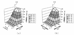
- the first heat generation efficiency map 30 shows the relationship between the exhaust gas temperature (DOC inlet temperature in the present embodiment), the exhaust gas SV ratio of the DOC 23, and the heat generation efficiency of the DOC 23.
- the higher the exhaust gas temperature the higher the heat generation efficiency.
- the heat generation efficiency tends to decrease as it increases once to reach a maximum value as the exhaust gas SV ratio increases.
- the second heat generation efficiency map 31 represents the relationship between the exhaust gas temperature and the exhaust gas air-fuel ratio ⁇ and the heat generation efficiency of the DOC 23.
- the higher the exhaust gas temperature the more heat is generated. Efficiency is high. Further, the heat generation efficiency has a tendency to increase once and reach a maximum value as the exhaust gas air-fuel ratio ⁇ increases, and then decrease.
- the poisoning prevention means 29 refers to the first and second heat generation efficiency maps 30 and 31 from the exhaust gas temperature T 1 , the exhaust gas SV ratio, and the exhaust gas air-fuel ratio ⁇ input to the ECU 28.
- the lower value is defined as the heat generation efficiency ⁇ of the DOC 23 so that the decrease in the catalytic activity of the DOC 23 can be quickly determined.
- the method of determining the heat generation efficiency ⁇ is not limited in the present invention, and the values obtained from the first and second heat generation efficiency maps 30 and 31 may be averaged to obtain the heat generation efficiency ⁇ of the DOC 23. good.
- the exhaust gas SV ratio and the exhaust gas air-fuel ratio ⁇ use values calculated by the ECU 28 from the operating state of the engine E (fuel injection instruction value, ignition timing, intake air amount, etc.). To do.
- a new ⁇ sensor air-fuel ratio sensor may be provided in the exhaust pipe 19 to directly detect the state of the exhaust gas in the exhaust pipe 19 and use the detected value.
- the poisoning prevention means 29 uses a base injection amount Q required to raise the exhaust gas to a target temperature (for example, about 350 to 450 ° C.) from the detected value (here, DOC outlet temperature) T 2 of the temperature sensor. 1 is calculated, the injection guard amount Q 2 is set according to the result of determining whether or not the heat generation amount of the DOC 23 is appropriate, and the injection guard amount Q 2 is subtracted from the base injection amount Q 1. Q is determined, and fuel is injected from the exhaust pipe injector 24 at the determined injection amount Q.
- a target temperature for example, about 350 to 450 ° C.
- the base injection amount Q 1 is an injection amount that is calculated from the temperature difference between the exhaust gas temperature T 2 and the target temperature and based on the insufficient amount of heat generated to raise the exhaust gas to the target temperature.
- the poisoning prevention means 29 sets the base injection amount Q 1 to be equal to or less than the upper limit injection amount Q sup that can maintain the catalytic activity of the DOC 23.
- the injection guard amount Q 2 is a value for reducing the injection amount Q of the exhaust pipe injector 24 to recover the DOC 23 from the HC poisoning when the DOC 23 is poisoned by the HC and the catalytic activity is reduced. Is set to the value of The injection guard amount Q 2 is decreased when the poisoning prevention unit 29 determines that the heat generation amount of the DOC 23 is appropriate, and is increased when it is determined that the heat generation amount of the DOC 23 is not appropriate.
- the present invention is not particularly limited with respect to the manipulated variable of the set value of the injection guard amount Q 2 , but for example, based on the calorific value difference between the integrated values J 1 and J 2 of the instantaneous calorific value C 1 and the estimated calorific value C 2.
- the injection amount Q may be gradually increased or decreased by reducing the operation amount per injection guard Q 2 .
- the upper limit injection amount Q sup is an upper limit injection amount at which the DOC 23 can maintain the catalytic activity without being poisoned by HC, and varies depending on the exhaust gas temperature, the exhaust gas air-fuel ratio, and the exhaust gas SV ratio of the DOC 23.
- the upper limit injection amount Q sup may be obtained in advance from a test operation of the DPF system 10 or may be obtained from a model calculation simulating the DPF system 10.
- the poisoning prevention means 29 according to the present embodiment can refer to the upper limit injection amount from the exhaust gas temperature (that is, the DOC inlet temperature T 1 ) detected by the temperature sensor 25 in front of the DOC 23 and the exhaust gas SV ratio of the DOC 23.
- the upper limit injection amount Q sup is obtained with reference to the upper limit injection amount maps 32 and 33.
- the first upper limit injection amount map 32 includes the exhaust gas temperature (DOC inlet temperature in the present embodiment), the exhaust gas SV ratio of the DOC 23, and the upper limit injection amount of the DOC 23. This represents the relationship, and the higher the exhaust gas temperature, the higher the upper limit injection amount. Further, the upper limit injection amount has a tendency to increase once the exhaust gas SV ratio increases and then decrease after reaching a maximum value.
- the second upper limit injection amount map 33 represents the relationship between the exhaust gas temperature, the exhaust gas air-fuel ratio, and the upper limit injection amount of the DOC 23. The higher the exhaust gas temperature, the higher the upper limit injection amount map 33 is. The upper limit injection amount is high. Further, the upper limit injection amount has a tendency to increase once and reach a maximum value as the exhaust gas air-fuel ratio ⁇ increases, and then decrease.
- the poisoning prevention means 29 refers to the first and second upper limit injection amount maps 32 and 33 from the exhaust gas temperature T 1 , the exhaust gas SV ratio, and the exhaust gas air-fuel ratio ⁇ input to the ECU 28.
- the lower value is set as the upper limit injection amount Q sup of the DOC 23, and the possibility of HC poisoning of the DOC 23 can be further reduced.
- the present invention is not limited to the determination method of the upper limit injection amount Q sup , and the values obtained from the first and second upper limit injection amount maps 32 and 33 are averaged to obtain the upper limit injection amount Q sup of the DOC 23. You may do it.
- poisoning prevention means 29 stores the injection guard amount Q 2 during DPF regeneration (the exhaust pipe injection), after the DPF regeneration is completed, based on the stored injection guard amount Q 2
- the first and second upper limit injection amount maps 32 and 33 are configured to be corrected. More specifically, the exhaust gas temperature T 1 , the exhaust gas SV ratio, and the exhaust gas air-fuel ratio ⁇ are stored in association with the injection guard amount Q 2 , and the first and second upper limit injections are based on these values.
- the quantity maps 32 and 33 are corrected.
- the first and second The upper limit injection amount maps 32 and 33 are corrected, but all the injection guard amounts Q 2 set during the DPF regeneration are associated with the exhaust gas temperature T 1 , the exhaust gas SV ratio, and the exhaust gas air-fuel ratio ⁇ . May be stored, and after the DPF regeneration, correction may be performed based on all the stored values.
- the DOC 23 is divided into the front DOC 23a and the rear DOC 23b in the front and rear halves, and the temperature sensor 27 is provided between the front DOC 23a and the rear DOC 23b.
- the temperature sensors 25 and 26 may be provided before and after the DOC.
- the temperature sensor 27 can detect the DOC center temperature T 3 , so that it is possible to respond more quickly to changes in the exhaust gas temperature.
- the DPF system 10 can be provided at a lower cost.
- HC-SCR HydroCarbon- Selective Catalytic Reduction
- LNT Lean NO x Trap
- LNT Lean NO x Trap
- the poisoning prevention means 29 mounted on the ECU 28 first performs step S21.
- the ECU 28 reads the DOC inlet temperature (exhaust gas temperature) T 1 , the exhaust gas SV ratio, and the exhaust gas air-fuel ratio ⁇ , and refers to the first and second upper limit injection amount maps 32 and 33. proceeds to step S22 to determine the upper-limit injection amount Q sup of DOC23 under the environment.
- step S22 the temperature difference between the heating target temperature and the DOC inlet temperature T 1 of the exhaust gas, it calculates the base injection amount Q 1 required the exhaust gas temperature to the target temperature, the base injection amount Q 1 And the upper limit injection amount Q sup are compared.
- the process proceeds to step S24.
- the process proceeds to step S23 to reduce the possibility of HC poisoning of the DOC 23, and the base injection amount Q 1 is set as the upper limit injection amount Q sup, and step S24. Proceed to
- step S24 the DOC inlet temperature T 1, the DOC center temperature T 3, a DOC outlet temperature T 2, the exhaust gas flow rate V, the heat capacity of the exhaust gas from, calculates the instantaneous calorific value C 1 of DOC23 The process proceeds to step S25.
- step S25 and see DOC inlet temperature (exhaust gas temperature) T 1 read at step S21, an exhaust gas SV ratio, the exhaust gas air-fuel ratio lambda, the first and second heat generating efficiency map 30 and 31 from Then, the heat generation efficiency ⁇ of the DOC 23 in the environment is determined, and then in step S26, the estimated heat generation amount C 2 of the DOC 23 is calculated from the heat generation efficiency ⁇ , the injection amount Q, and the lower heat generation amount of the fuel.
- step S27 from the lower heating value of the injection amount Q and the fuel to calculate the theoretical calorific value C 3 of DOC 23.
- the exhaust pipe injector 24 does not perform exhaust pipe injection, so the injection amount Q is 0, and the calculated estimated heat generation amount C 2 and theoretical heat generation amount C 3 are also 0. .
- steps S21 to S27 are executed again after the injection amount Q is determined through steps S28 to S38, which will be described later, and the exhaust pipe injection is performed again, a predetermined amount of injection amount Q is set. The amount will be calculated.
- step S28 the calculated instantaneous calorific value C 1 , estimated calorific value C 2 and theoretical calorific value C 3 are accumulated, and the instantaneous calorific value C 1 , estimated calorific value C 2 and theoretical calorific value C 3 are accumulated.
- the values J 1 , J 2 , J 3 are obtained and the process proceeds to step S29.
- this invention is not limited about the integration time range for calculating
- step S29 the time from the start of DPF regeneration (exhaust pipe injection) has passed a delay time t d in anticipation of the time lag until the exhaust gas injected into the exhaust pipe reaches the temperature sensors 25 to 27. It is determined whether or not.
- a delay not elapsed time t d is, DOC 23 is not generating heat, it can not determine proper or not calorific value of DOC 23, and the injection guard amount Q 2 and 0 proceeds to step S30, in step S37 move on.
- the delay time t d has elapsed, the process proceeds to step S31 in order to determine whether or not the amount of heat generated by the DOC 23 is appropriate.
- the time until the fuel injected into the exhaust pipe reaches the temperature sensors 25 to 27 varies depending on the configuration of the DPF system 10 (for example, the length and cross-sectional area of the exhaust pipe 19) and the exhaust gas flow rate V.
- the delay time t d may be set as a fixed value that can at least guarantee that the exhaust gas injected into the exhaust pipe has reached the temperature sensors 25 to 27. Further, the delay time t d may be calculated and updated each time based on the configuration of the DPF system 10 and the exhaust gas flow rate V.
- step S31 the integrated values J 2 and J 3 of the estimated heat value C 2 and the theoretical heat value C 3 obtained in step S28 are compared, and the integrated value J 3 of the theoretical heat value C 3 is the integrated value of the estimated heat value C 2 .
- the process proceeds to step S34.
- the integrated value J 3 theoretical calorific value C 3 is smaller than the integrated value J 2 of the estimated heat generation amount C 2, 0 of the integrated value J 3 theoretical calorific value C 3 of the threshold J th proceeds to step S33. Set to 8 and proceed to step S34.
- step S34 the integrated value J 1 of the instantaneous heat generation amount C 1 calculated in step S28, it is compared with a threshold value J th obtained in step S32 or step S33, whether the heat value of DOC23 is appropriate to decide. More specifically, when the integrated value J 1 of the instantaneous heat generation amount C 1 is equal to or less than the threshold value J th, it is determined that the heat generation amount of the DOC 23 is not appropriate (that is, the DOC 23 is HC poisoned), and step S35. increase the set value of the injection guard quantity Q 2 proceeds, the process proceeds to step S37.
- the calorific value of DOC 23 is appropriate (i.e., DOC 23 is not HC poisoning) it determines that the injection proceeds to step S36 decrease the value of the guard quantity Q 2, the process proceeds to step S37. Because the present embodiment is small operation amount per single injection guard quantity Q 2, now injection amount Q for each execution of step S35 or step S36 is increased or decreased gradually, the step S35 or step S36 By being repeated, the injection amount Q gradually converges to a value that matches the degree of deterioration of the catalytic activity of the DOC 23.
- step S37 the base injection amount Q 1 determined in step S21 ⁇ S23, in step S30, S35, S36 by subtracting the injection guard amount Q 2 to which set in search of injection quantity Q, the injection amount Q Fuel is injected from the exhaust pipe injector 24.
- the poisoning prevention means 29 stores the set injection guard amount Q 2 in association with the DOC inlet temperature T 1 , the exhaust gas SV ratio, and the exhaust gas air-fuel ratio ⁇ read in step S21.
- step S38 it is determined whether or not the DPF regeneration is completed.
- the process returns to step S21.
- the process proceeds to step S39, where the first and first values are based on the injection guard amount Q 2 , the DOC inlet temperature T 1 , the exhaust gas SV ratio, and the exhaust gas air-fuel ratio ⁇ stored in step S37.
- the two upper limit injection amount maps 32 and 33 are integrated and corrected, and the control is terminated.
- the injection amount Q, the exhaust gas temperatures T 1 , T 2 , T 3 , the exhaust gas SV ratio, and the exhaust gas air-fuel ratio are added with little cost. From ⁇ , it is determined whether or not the heat generation amount of the DOC 23 is appropriate, and the injection amount Q is increased or decreased according to the determination. Therefore, when the DOC 23 is poisoned by HC and the catalytic activity is reduced, the injection amount Q is decreased. Thus, the catalytic activity of the DOC 23 can be quickly recovered, and the melting damage due to abnormal combustion of the DOC 23 can be prevented.
Landscapes
- Engineering & Computer Science (AREA)
- Chemical & Material Sciences (AREA)
- Combustion & Propulsion (AREA)
- Mechanical Engineering (AREA)
- General Engineering & Computer Science (AREA)
- Chemical Kinetics & Catalysis (AREA)
- Health & Medical Sciences (AREA)
- Toxicology (AREA)
- Materials Engineering (AREA)
- Processes For Solid Components From Exhaust (AREA)
- Exhaust Gas After Treatment (AREA)
Abstract
排気管噴射による排気ガスの昇温制御を行う際に、HC被毒によるDOCの触媒活性不良を防ぐことができるDPFシステムを提供する。 排気管インジェクタ24から燃料を噴射し、これをDOC23で酸化燃焼させてDPFに堆積したPMを燃焼除去するDPF再生を行うDPFシステム10において、DOC23の前後に設けられた温度センサ25,26と、排気管インジェクタ24の噴射量Qと温度センサの検出値T1,T2とが入力され、入力された噴射量Qと検出値T1,T2とからDOC23の発熱量が適正か否かを判断する被毒防止手段29と、を備えるものである。
Description
本発明はディーゼルエンジンの排気ガスから粒子状物質をDPFで捕集し、これを排気管噴射により燃焼除去するDPFシステムに関する。
従来から、ディーゼルエンジンの排気ガスからPM(Particulate Matter)を浄化するためのDPF(Diesel Particulate Filter)システムの開発が行われている(例えば、特許文献1参照)。このDPFシステムでは、DPFと呼ばれるフィルタを排気管に接続して排気ガスからPMを捕集すると共に、DPFの上流側に設けられたDOC(Diesel Oxidation Catalyst)で排気ガス中のNOxをNO2とし、このNO2の酸化力でPMを酸化(燃焼)させてPMを除去することが行われる。
また、PMの除去が促進されずDPFにPMが堆積する場合には、排気ガス中に未燃燃料を添加し、この燃料をDOCで酸化燃焼させて排気ガスの温度を昇温させ、DPFに堆積したPMを強制的に燃焼除去するDPF再生が行われる。排気ガスに未燃燃料を添加する手段としては、燃焼行程を終えた直後のエンジン筒内に燃料インジェクタから未燃燃料を噴射するポスト噴射と、DOCよりも上流側の排気管に設けた排気管インジェクタから未燃燃料を噴射する排気管噴射がある。
ポスト噴射は従来のエンジンシステムの構成のままで実行可能であるが、エンジン筒内のオイル希釈、排気ガスのスモーク発生、運転性への影響などの問題がある。一方、排気管噴射では上述の問題を発生させることなく排気ガスを昇温し、DPF再生を行うことができる。
ところで、ポスト噴射ではエンジンが燃焼行程を終えた直後の上死点付近で噴射を行うため、燃焼行程直後の高温で分解される燃料は、活性化しやすい短鎖のHC(HydroCarbon)となる。一方、排気管噴射では排気ガスが比較的低温の排気管内で噴射を行うため、添加された燃料は活性化し難い長鎖のHCとなる。
長鎖のHCは燃焼しがたく、噴射量の増加時には、DOCにHCが吸着してHC被毒となり、失火し易い(触媒活性が低下し易い)等のデメリットがある。
図5は、排気管噴射を行うDPFシステムにおいて、排気管噴射の燃料噴射量(排気噴射量)と、DOC(酸化触媒)の温度変化との関係を示す図であり、DOCの入口側(上流側)で計測される温度(DOC入口温度)、DOCの中心で計測される排気ガス温度(DOC中心温度)およびDOCの出口側(下流側)で計測される排気ガス温度(DOC出口温度)の経時変化を示している。
排気噴射量を約5,約10mm3/stとして排気管噴射したとき、DOC中心温度およびDOC出口温度は略一定の値に昇温されており、DOCの触媒活性が失われることなく排気ガスを安定的に昇温できていることがわかる。
しかしながら排気噴射量を約15mm3/stとしたとき、噴射開始時にはDOC中心温度およびDOC出口温度が一時的に昇温されるものの、排気ガスに含まれる多量のHCがDOCに吸着し、DOCの触媒活性が低下して(DOCが失火して)温度が急激に減少している。
DOCがHC被毒して失火すると、排気ガスを昇温制御できず、PMを燃焼させてDPF再生を行うことができない。さらに、HC被毒後にDOCの温度が上昇すると吸着したHCが燃焼するようになるが、HCが一気に燃焼して異常燃焼となり、最悪の場合にはDOCの溶損が発生する可能性もある。
また、DOCの触媒活性は、運転条件の変化やDPF再生の繰返しによる触媒の劣化などにより変化する虞があり、触媒の劣化前と同じ噴射量で排気ガスに未燃燃料を添加し続けると、上述のHC被毒やDOC溶損の可能性がさらに増大する。
本発明は上記課題を解決するためになされたものであり、排気管噴射による排気ガスの昇温制御を行う際に、HC被毒によるDOCの触媒活性不良を防ぐことができるDPFシステムを提供することを目的とする。
上記目的を達成するために本発明は、排気管インジェクタから燃料を噴射し、これをDOCで酸化燃焼させてDPFに堆積したPMを燃焼除去するDPF再生を行うDPFシステムにおいて、前記DOCの前後に設けられた温度センサと、前記排気管インジェクタの噴射量と前記温度センサの検出値とが入力され、入力された前記噴射量と前記検出値とから前記DOCの発熱量が適正か否かを判断する被毒防止手段と、を備えるものである。
前記被毒防止手段は、前記温度センサの検出値と排気ガス流量とから前記DOCの瞬時発熱量を計算して積算すると共に、前記排気管インジェクタの噴射量と前記DOCの発熱効率とから推定発熱量を計算して積算し、前記推定発熱量の積算値から所定値低い閾値を設定し、前記瞬時発熱量の積算値が前記閾値より大きいとき、前記DOCの発熱量が適正であると判断し、前記瞬時発熱量の積算値が前記閾値以下であるとき、前記DOCの発熱量が適正でないと判断すると良い。
前記被毒防止手段は、前記噴射量から理論発熱量を算出して積算し、その理論発熱量の積算値が前記推定発熱量の積算値より小さいときには、前記閾値を前記理論発熱量の積算値から所定値低く設定すると良い。
前記被毒防止手段は、前記DOC前方の温度センサの検出値と前記DOCの排気ガスSV比とから前記発熱効率を参照可能な第1の発熱効率マップと、前記DOC前方の温度センサの検出値と排気ガス空燃比とから前記発熱効率を参照可能な第2の発熱効率マップと、を有し、前記第1及び第2の発熱効率マップを参照して前記発熱効率を求めると良い。
前記被毒防止手段は、前記温度センサの検出値から前記排気ガスを目標温度に昇温させるためのベース噴射量を算出すると共に、前記DOCの発熱量が適正であるか否かを判断した結果に応じて噴射ガード量を設定し、前記ベース噴射量から前記噴射ガード量を減算して前記噴射量を求め、求めた噴射量で前記排気管インジェクタから燃料を噴射させると良い。
前記被毒防止手段は、前記DOCの発熱量が適正であると判断したとき、前記噴射ガード量の設定値を小さくし、前記DOCの発熱量が適正でないと判断したとき、前記噴射ガード量の設定値を大きくすると良い。
前記被毒防止手段は、前記ベース噴射量を、前記DOCの触媒活性が保てる上限噴射量以下とさせると良い。
前記被毒防止手段は、前記DOC前方の温度センサの検出値と前記DOCの排気ガスSV比とから前記上限噴射量を参照可能な第1の上限噴射量マップと、前記DOC前方の温度センサの検出値と排気ガス空燃比とから前記上限噴射量を参照可能な第2の上限噴射量マップと、を有し、前記第1及び第2の上限噴射量マップを参照して前記上限噴射量を求めると良い。
前記被毒防止手段は、前記噴射ガード量を記憶しておき、前記DPF再生後に、記憶しておいた前記噴射ガード量に基づいて、前記第1及び第2の上限噴射量マップを補正すると良い。
前記DOCが前後に2分割されると共に、その2分割されたDOC間に温度センサが設けられると良い。
本発明によれば、排気管噴射による排気ガスの昇温制御を行う際に、HC被毒によるDOCの触媒活性不良を防ぐことができるDPFシステムを提供できる。
以下に、本発明の好適な実施の形態について図面に基づき説明する。
図1は、本実施の形態に係るDPFシステムの構成を示す図である。
本実施の形態のDPFシステム10はターボチャージャ11を搭載しており、エアクリーナ12から吸入される空気はターボチャージャ11のコンプレッサ13で圧縮されると共に吸気通路14に圧送され、吸気通路14に接続された吸気マニホールド15からエンジンEに供給される。吸気通路14には、エンジンEへの空気量を調節するための吸気バルブ16が設けられる。
エンジンEから排出される排気ガスは排気マニホールド17からターボチャージャ11のタービン18に流入すると共にタービン18を駆動させ、排気管19に排気される。
このDPFシステム10は、吸気マニホールド15と排気マニホールド17とを接続するEGR管20と、EGR管20を通過する排気ガスを冷却するためのEGRクーラ21と、排気マニホールド17から吸気マニホールド15へ還流させる排気ガス量を調節するためのEGRバルブ22と、を備え、排気ガスの一部を吸気側へ還流させてエンジンアウトのNOx量を低減させるEGR制御を行う。
排気管19にはDOC23が配設され、そのDOC23の上流側の排気管19には排気管インジェクタ24が、下流側の排気管19には排気ガスからPMを捕集するためのDPF34が設けられる。本実施の形態では、DOC23を前方(上流側)DOC23aおよび後方(下流側)DOC23bに前後2分割した構造とする。
さらに排気管19には、前方DOC23aの前方(上流側)、後方DOC23bの後方(下流側)および前方DOC23aと後方DOC23bとの間に温度センサ25,26,27が設けられる。
エンジンE、吸気バルブ16、EGRバルブ22、排気管インジェクタ24、温度センサ25~27はECU(Electronical Control Unit)28と接続され、ECU28には温度センサ25~27からの信号が入力される。またECU28は、エンジンEの運転、吸気バルブ16およびEGRバルブ22の開度、排気管インジェクタ24の排気管噴射等を制御する。この他にもECU28には車両に搭載される各種センサからの信号が入力されると共に、排気ガス流量および排気ガス空燃比の計算などを行う。
さて、このDPFシステム10では、エンジンEから排出された排気ガス中に含まれるPMをDPF34で捕集し、DPF34に堆積したPMを燃焼除去してDPF再生を行うべく、排気ガスに排気管インジェクタ24から燃料を添加し(排気管噴射し)、この燃料をDOC23で酸化燃焼させて排気ガスを昇温することが行われる。
このとき、DOC23の触媒活性以上に未燃燃料が添加されると、排気管噴射された燃料がDOC23上に吸着されてDOC23の触媒活性が失われ、DOC23の発熱量が低下して、DPF再生できなくなる虞がある。
そこで本実施の形態に係るDPFシステム10では、排気管インジェクタ24から排気管噴射された燃料の噴射量Qと温度センサ25,26,27からの検出値T1,T2,T3とが入力されると共に、入力された噴射量と検出値とからDOC23の発熱量が適正か否かを判断する被毒防止手段29がECU28に搭載される。
被毒防止手段29は、温度センサ25の検出値(DOC入口温度)T1、温度センサ26の検出値(DOC出口温度)T2、温度センサ27の検出値(DOC中心温度)T3と、排気ガス流量VとからDOC23の瞬時発熱量C1を計算して積算し、他方、排気管インジェクタ24の噴射量QとDOC23の発熱効率κとから推定発熱量C2を計算して積算し、推定発熱量C2の積算値J2から所定値低い閾値Jthを設定するようにされる。瞬時発熱量C1は、DOC23の排気ガス温度から求められる実際の発熱量であり、推定発熱量C2は、噴射量Qと発熱効率κとから推定される発熱量である。さらに被毒防止手段29は、瞬時発熱量C1の積算値J1と閾値Jthとを比較し、瞬時発熱量C1の積算値J1が閾値Jth以下であるとき、DOC23の発熱量が適正でないと判断し、瞬時発熱量C1の積算値J1が閾値Jthよりも大きいとき、DOC23の発熱量が適正であると判断するように構成される。
また、被毒防止手段29は、噴射量Qから理論発熱量C3を算出して積算し、その理論発熱量C3の積算値J3が推定発熱量C2の積算値J2より小さいときには、閾値Jthを理論発熱量C3の積算値J3から所定値低く設定するように構成される。理論発熱量C3は、燃料がDOC23上で完全燃焼したときの発熱量であり、DOC23上での実際の発熱量は、理論発熱量C3を超えない。推定発熱量C2の積算値J2が実際の発熱量より大きく算出されるような運転条件ではDOC23の発熱量が適正か否かの判断が不確実となることから、このような運転条件においては理論発熱量C3の積算値J3を基に閾値Jthを設定することで、DOC23の触媒活性の低下をより確実に判断できる。
閾値Jthは、排気管噴射の噴射量Qに対してDOC23の発熱量が適正か否かを判断するための値であり、本実施の形態では推定発熱量C2の積算値J2あるいは理論発熱量C3の積算値J3の0.8掛け(推定発熱量C2の積算値J2×0.8あるいは理論発熱量C3の積算値J3×0.8)に設定され、推定発熱量C2あるいは理論発熱量C3の積算値J2,J3よりも低い値に設定される。ただし、本発明は閾値Jthの設定方法について限定されるものではなく、推定発熱量C2あるいは理論発熱量C3の積算値J2,J3から所定の熱量を減算した閾値Jthを設定するようにしても良い。
発熱効率κは、噴射量Qの完全燃焼時の発熱量に対するDOC23上での所定の条件での発熱量の割合を示す値であり、排気ガス温度、排気ガス空燃比、DOC23の排気ガスSV比により0~1の範囲で変化する。発熱効率κは、予めDPFシステム10の試験運転から求めても良く、DPFシステム10を模したモデル計算から求めても良い。本実施の形態では、被毒防止手段29は、DOC23前方の温度センサ25で検出される排気ガス温度(すなわち、DOC入口温度T1)とDOC23の排気ガスSV比とから発熱効率を参照可能な第1の発熱効率マップ30と、DOC入口温度T1と排気ガス空燃比λとから発熱効率を参照可能な第2の発熱効率マップ31と、を有し、第1及び第2の発熱効率マップ30,31を参照して発熱効率κを求めるようにされる。
第1及び第2の発熱効率マップ30,31の一例を図3に示す。第1の発熱効率マップ30は、図3(a)に示すように、排気ガス温度(本実施の形態では、DOC入口温度)およびDOC23の排気ガスSV比と、DOC23の発熱効率との関係を表すものであり、排気ガス温度が高いほど発熱効率は高い。また発熱効率は、排気ガスSV比が高くなるに伴い、一旦増加して極大値となった後に減少する傾向を有する。第2の発熱効率マップ31は、図3(b)に示すように、排気ガス温度および排気ガス空燃比λと、DOC23の発熱効率との関係を表すものであり、排気ガス温度が高いほど発熱効率は高い。また発熱効率は、排気ガス空燃比λが高くなるに伴い、一旦増加して極大値となった後に減少する傾向を有する。
本実施の形態では、被毒防止手段29はECU28に入力される排気ガス温度T1、排気ガスSV比、排気ガス空燃比λから第1及び第2の発熱効率マップ30,31を参照し、求めた値のうち、より低い値をDOC23の発熱効率κとし、DOC23の触媒活性の低下を速やかに判断できるように構成される。ただし、本発明は発熱効率κの決定方法を限定されるものではなく、第1及び第2の発熱効率マップ30,31から求めた値を平均化してDOC23の発熱効率κとするなどしても良い。なお、本実施の形態では、排気ガスSV比および排気ガス空燃比λは、ECU28がエンジンEの運転状態(燃料噴射指示値、点火時期、吸入空気量など)から計算出力した値を用いることとする。ただし、排気管19に新たにλセンサ(空燃比センサ)を設けるなどし、排気管19内の排気ガスの状態を直接検出して、検出した値を用いるようにしても良い。
さらに被毒防止手段29は、温度センサの検出値(ここではDOC出口温度)T2から、排気ガスを目標温度(例えば、約350~450℃)に昇温させるために必要なベース噴射量Q1を算出すると共に、DOC23の発熱量が適正であるか否かを判断した結果に応じて噴射ガード量Q2を設定し、ベース噴射量Q1から噴射ガード量Q2を減算して噴射量Qを求め、求めた噴射量Qで排気管インジェクタ24から燃料を噴射させるように構成される。
ベース噴射量Q1は、排気ガス温度T2と目標温度との温度差から、排気ガスを目標温度へ昇温するために必要な不足分の発熱量を基に算出される噴射量である。本実施の形態では、DOC23がHC被毒する可能性を減らすため、被毒防止手段29は、ベース噴射量Q1をDOC23の触媒活性が保てる上限噴射量Qsup以下とさせる。
噴射ガード量Q2は、DOC23がHC被毒して触媒活性が低下したとき、DOC23をHC被毒から回復させるべく、排気管インジェクタ24の噴射量Qを減少させるための値であり、0以上の値に設定される。この噴射ガード量Q2は、被毒防止手段29がDOC23の発熱量が適正であると判断したときには設定値を小さくされ、DOC23の発熱量が適正でないと判断したときには設定値を大きくされる。本発明は、噴射ガード量Q2の設定値の操作量について特に限定されるものではないが、例えば瞬時発熱量C1および推定発熱量C2の積算値J1,J2の熱量差を基に過不足分の噴射量を算出し、この算出した値より所定割合低い操作量で噴射ガード量Q2の設定値を変更するか、あるいは、噴射ガード量Q2の操作量を所定の固定値とし、噴射ガード量Q2の一回あたりの操作量を小さくして噴射量Qが徐々に増減するようにされると良い。
上限噴射量Qsupは、DOC23がHC被毒せず触媒活性を保てる上限の噴射量であり、排気ガス温度、排気ガス空燃比、DOC23の排気ガスSV比により変化する。上限噴射量Qsupは、予めDPFシステム10の試験運転から求めても良く、DPFシステム10を模したモデル計算から求めても良い。本実施の形態に係る被毒防止手段29は、DOC23前方の温度センサ25で検出される排気ガス温度(すなわち、DOC入口温度T1)とDOC23の排気ガスSV比とから上限噴射量を参照可能な第1の上限噴射量マップ32と、DOC入口温度T1と排気ガス空燃比λとから上限噴射量を参照可能な第2の上限噴射量マップ33と、を有し、第1及び第2の上限噴射量マップ32,33を参照して上限噴射量Qsupを求めるようにされる。
第1及び第2の上限噴射量マップ32,33の一例を図4に示す。第1の上限噴射量マップ32は、図4(a)に示すように、排気ガス温度(本実施の形態では、DOC入口温度)およびDOC23の排気ガスSV比と、DOC23の上限噴射量との関係を表すものであり、排気ガス温度が高いほど上限噴射量は高い。また上限噴射量は、排気ガスSV比が高くなるに伴い、一旦増加して極大値となった後に減少する傾向を有する。第2の上限噴射量マップ33は、図4(b)に示すように、排気ガス温度および排気ガス空燃比と、DOC23の上限噴射量との関係を表すものであり、排気ガス温度が高いほど上限噴射量は高い。また上限噴射量は、排気ガス空燃比λが高くなるに伴い、一旦増加して極大値となった後に減少する傾向を有する。
本実施の形態では、被毒防止手段29はECU28に入力される排気ガス温度T1、排気ガスSV比、排気ガス空燃比λから第1及び第2の上限噴射量マップ32,33を参照し、求めた値のうち、より低い値をDOC23の上限噴射量Qsupとし、DOC23のHC被毒の可能性をより低減できるように構成される。ただし、本発明は上限噴射量Qsupの決定方法を限定されるものではなく、第1及び第2の上限噴射量マップ32,33から求めた値を平均化してDOC23の上限噴射量Qsupとするなどしても良い。
また、被毒防止手段29はDPF再生中(排気管噴射中)に噴射ガード量Q2を記憶しておき、そのDPF再生が完了した後に、記憶しておいた噴射ガード量Q2に基づいて、第1及び第2の上限噴射量マップ32,33を補正するように構成される。より具体的には、噴射ガード量Q2と共に排気ガス温度T1、排気ガスSV比、排気ガス空燃比λを関連づけて記憶しておき、これらの値に基づいて第1及び第2の上限噴射量マップ32,33を補正するようにされる。
次回DPF再生時には、補正した第1及び第2の上限噴射量マップ32,33を用いてDOC23の上限噴射量Qsupを求めるようにし、DPF再生毎に、第1及び第2の上限噴射量マップ32,33を噴射ガード量Q2に基づいて積算補正する。この補正は、記憶しておいた噴射ガード量Q2を一次遅れフィルタ処理して行うと、外乱などの影響でマップ補正量が大きく乱れて上限噴射量Qsupの値が不安定となることを防止できる。なお、本実施の形態では、DPF再生完了直前の噴射ガード量Q2と、そのときの排気ガス温度T1,排気ガスSV比,排気ガス空燃比λとに基づいて、第1及び第2の上限噴射量マップ32,33を補正するようにされるが、DPF再生中に設定された全ての噴射ガード量Q2を、排気ガス温度T1,排気ガスSV比,排気ガス空燃比λと関連づけて記憶しておき、DPF再生後に、記憶しておいた全ての値に基づいて補正を行っても良い。
本実施の形態のDPFシステム10では、DOC23を前方DOC23aと後方DOC23bとに前後2分割し、前方DOC23aと後方DOC23bとの間に温度センサ27を設けた構成としているが、DOC23を前後2分割せず、DOCの前後に温度センサ25,26を設ける構成としても良い。DOC23を前後2分割とした構成では、温度センサ27でDOC中心温度T3を検出できるので、排気ガス温度の変化に対して、より迅速に対応できることとなる。他方、DOC23を前後2分割としない構成では、DPFシステム10をより安価に提供できる。また、DPF以外にも、排気ガス中のNOxを浄化するためのHC-SCR(HydroCarbon-Selective Catalytic Reduction)装置、LNT(Lean NOx Trap)装置などを排気管19に接続しても良い。
次に、被毒防止手段29の動作について図2を用いて説明する。
所定の距離を走行するなどし、DPF34にPMが堆積していると判断したECU28がPMを燃焼除去すべくDPF再生を開始したとき、ECU28に搭載される被毒防止手段29は、先ずステップS21において、ECU28からDOC入口温度(排気ガス温度)T1と、排気ガスSV比と、排気ガス空燃比λと、を読み込んで、第1及び第2の上限噴射量マップ32,33を参照し、当該環境下でのDOC23の上限噴射量Qsupを決定してステップS22に進む。
ステップS22では、排気ガスの昇温目標温度とDOC入口温度T1との温度差から、排気ガス温度を目標温度とするのに必要なベース噴射量Q1を算出し、このベース噴射量Q1と上限噴射量Qsupとを比較する。ベース噴射量Q1が上限噴射量Qsupより小さいときには、ステップS24に進む。他方、ベース噴射量Q1が上限噴射量Qsupよりも大きいときには、DOC23のHC被毒の可能性を減らすべく、ステップS23に進んでベース噴射量Q1を上限噴射量Qsupとし、ステップS24へ進む。
ステップS24では、DOC入口温度T1と、DOC中心温度T3と、DOC出口温度T2と、排気ガス流量Vと、排気ガスの熱容量と、から、DOC23の瞬時発熱量C1を算出して、ステップS25に進む。
ステップS25では、ステップS21で読み込んだDOC入口温度(排気ガス温度)T1と、排気ガスSV比と、排気ガス空燃比λと、から第1及び第2の発熱効率マップ30,31を参照し、当該環境下でのDOC23の発熱効率κを決定し、次いでステップS26にて発熱効率κと噴射量Qと燃料の低位発熱量とから、DOC23の推定発熱量C2を算出する。
続くステップS27では、噴射量Qと燃料の低位発熱量とから、DOC23の理論発熱量C3を算出する。なお、DPF再生を開始した直後では、排気管インジェクタ24は排気管噴射を行っていないため、噴射量Qは0であり、算出される推定発熱量C2および理論発熱量C3も0となる。後述するステップS28~S38を経て噴射量Qを決定して排気管噴射を行った後に、ステップS21~S27が再度実行されたときには、所定量の噴射量Qが設定されているので、所定の発熱量が算出されることとなる。
しかる後、ステップS28において、算出した瞬時発熱量C1,推定発熱量C2および理論発熱量C3をそれぞれ積算し、瞬時発熱量C1,推定発熱量C2および理論発熱量C3の積算値J1,J2,J3を求め、ステップS29に進む。なお本発明は、積算値を求めるための積算時間範囲について限定されるものではなく、適宜変更可能である。積算時間範囲を大きくすると外乱による判断の乱れを小さくでき、積算時間範囲を小さくするとDOC23の触媒活性の変化を迅速に判断できる。
ステップS29では、DPF再生(排気管噴射)を開始してからの時間が、排気管噴射された排気ガスが温度センサ25~27に到達するまでのタイムラグを見越した遅れ時間tdを経過しているか否かを判定する。遅れ時間tdを経過していないときには、DOC23は発熱しておらず、DOC23の発熱量が適正か否かを判断できないので、ステップS30に進んで噴射ガード量Q2を0とし、ステップS37に進む。他方、遅れ時間tdを経過しているときには、DOC23の発熱量が適正か否かを判断すべく、ステップS31に進む。なお、排気管噴射された燃料が温度センサ25~27に到達するまでの時間は、DPFシステム10の構成(例えば、排気管19の長さおよび断面積など)や排気ガス流量Vにより変化するが、遅れ時間tdは、排気管噴射された排気ガスが温度センサ25~27に到達していることを最低限保証できる固定値として設定すれば良い。また、DPFシステム10の構成と排気ガス流量Vとを基に、遅れ時間tdを都度計算して更新するようにしても良い。
ステップS31では、ステップS28で求めた推定発熱量C2および理論発熱量C3の積算値J2,J3を比較し、理論発熱量C3の積算値J3が推定発熱量C2の積算値J2以上であるとき、ステップS32に進んで閾値Jthを推定発熱量C2の積算値J2の0.8掛けに設定し、ステップS34に進む。他方、理論発熱量C3の積算値J3が推定発熱量C2の積算値J2よりも小さいとき、ステップS33に進んで閾値Jthを理論発熱量C3の積算値J3の0.8掛けに設定し、ステップS34に進む。
ステップS34では、ステップS28で求めた瞬時発熱量C1の積算値J1と、ステップS32あるいはステップS33で求めた閾値Jthとを比較して、DOC23の発熱量が適正であるか否かを判断する。より具体的には、瞬時発熱量C1の積算値J1が閾値Jth以下であるとき、DOC23の発熱量が適正でない(すなわち、DOC23がHC被毒している)と判断し、ステップS35に進んで噴射ガード量Q2の設定値を大きくし、ステップS37に進む。他方、瞬時発熱量C1の積算値J1が閾値Jthより大きいとき、DOC23の発熱量が適正である(すなわち、DOC23がHC被毒していない)と判断し、ステップS36に進んで噴射ガード量Q2の設定値を小さくし、ステップS37に進む。本実施の形態では噴射ガード量Q2の一回あたりの操作量を小さくされるため、ステップS35あるいはステップS36の実行毎に噴射量Qが徐々に増減するようになり、ステップS35あるいはステップS36が繰り返されることで、噴射量Qが、DOC23の触媒活性の劣化度合いに合わせた値に徐々に収束していくこととなる。
しかる後、ステップS37では、ステップS21~S23で求めたベース噴射量Q1から、ステップS30,S35,S36で設定した噴射ガード量Q2を減算して噴射量Qを求め、この噴射量Qで排気管インジェクタ24から燃料を噴射させる。このとき、被毒防止手段29は、設定した噴射ガード量Q2を、ステップS21で読み込んだDOC入口温度T1、排気ガスSV比および排気ガス空燃比λと関連づけて記憶しておく。
その後、ステップS38においてDPF再生が完了したかどうかを判断する。DPF再生が未完了であるときにはステップS21に戻る。DPF再生が完了しているときにはステップS39に進み、ステップS37で記憶しておいた噴射ガード量Q2、DOC入口温度T1、排気ガスSV比および排気ガス空燃比λに基づいて第1及び第2の上限噴射量マップ32,33を積算補正して制御を終了する。
以上説明したように、本実施の形態に係るDPFシステム10では、殆どコストを追加することなく、噴射量Q、排気ガス温度T1,T2,T3、排気ガスSV比、排気ガス空燃比λからDOC23の発熱量が適正か否かを判断し、その判断に応じて噴射量Qを増減するようにされるため、DOC23がHC被毒して触媒活性が低下したときには噴射量Qを減少させ、DOC23の触媒活性を速やかに回復させることができ、DOC23の異常燃焼による溶損を防止できる。
また、第1及び第2の上限噴射量マップ32,33から求めた上限噴射量Qsup以下で排気管噴射するため、DOC23がHC被毒する可能性をさらに低減できる。
さらに、DPF再生終了後には噴射ガード量Q2に基づいて第1及び第2の上限噴射量マップ32,33を補正するため、運転条件変化や触媒劣化によるDOC23の触媒活性の変化にも対応できる。
10 DPFシステム
23 DOC
24 排気管インジェクタ
25 温度センサ
26 温度センサ
29 被毒防止手段
Q 噴射量
T1 温度センサの検出値(排気ガス温度)
T2 温度センサの検出値(排気ガス温度)
23 DOC
24 排気管インジェクタ
25 温度センサ
26 温度センサ
29 被毒防止手段
Q 噴射量
T1 温度センサの検出値(排気ガス温度)
T2 温度センサの検出値(排気ガス温度)
Claims (10)
- 排気管インジェクタから燃料を噴射し、これをDOCで酸化燃焼させてDPFに堆積したPMを燃焼除去するDPF再生を行うDPFシステムにおいて、
前記DOCの前後に設けられた温度センサと、
前記排気管インジェクタの噴射量と前記温度センサの検出値とが入力され、入力された前記噴射量と前記検出値とから前記DOCの発熱量が適正か否かを判断する被毒防止手段と、を備えることを特徴とするDPFシステム。 - 前記被毒防止手段は、前記温度センサの検出値と排気ガス流量とから前記DOCの瞬時発熱量を計算して積算すると共に、
前記排気管インジェクタの噴射量と前記DOCの発熱効率とから推定発熱量を計算して積算し、
前記推定発熱量の積算値から所定値低い閾値を設定し、前記瞬時発熱量の積算値が前記閾値より大きいとき、前記DOCの発熱量が適正であると判断し、前記瞬時発熱量の積算値が前記閾値以下であるとき、前記DOCの発熱量が適正でないと判断する請求項1記載のDPFシステム。 - 前記被毒防止手段は、前記噴射量から理論発熱量を算出して積算し、その理論発熱量の積算値が前記推定発熱量の積算値より小さいときには、前記閾値を前記理論発熱量の積算値から所定値低く設定する請求項2記載のDPFシステム。
- 前記被毒防止手段は、前記DOC前方の温度センサの検出値と前記DOCの排気ガスSV比とから前記発熱効率を参照可能な第1の発熱効率マップと、
前記DOC前方の温度センサの検出値と排気ガス空燃比とから前記発熱効率を参照可能な第2の発熱効率マップと、を有し、
前記第1及び第2の発熱効率マップを参照して前記発熱効率を求める請求項2又は3記載のDPFシステム。 - 前記被毒防止手段は、前記温度センサの検出値から前記排気ガスを目標温度に昇温させるためのベース噴射量を算出すると共に、前記DOCの発熱量が適正であるか否かを判断した結果に応じて噴射ガード量を設定し、前記ベース噴射量から前記噴射ガード量を減算して前記噴射量を求め、求めた噴射量で前記排気管インジェクタから燃料を噴射させる請求項1~4いずれかに記載のDPFシステム。
- 前記被毒防止手段は、前記DOCの発熱量が適正であると判断したとき、前記噴射ガード量の設定値を小さくし、前記DOCの発熱量が適正でないと判断したとき、前記噴射ガード量の設定値を大きくする請求項5記載のDPFシステム。
- 前記被毒防止手段は、前記ベース噴射量を、前記DOCの触媒活性が保てる上限噴射量以下とさせる請求項5又は6記載のDPFシステム。
- 前記被毒防止手段は、前記DOC前方の温度センサの検出値と前記DOCの排気ガスSV比とから前記上限噴射量を参照可能な第1の上限噴射量マップと、
前記DOC前方の温度センサの検出値と排気ガス空燃比とから前記上限噴射量を参照可能な第2の上限噴射量マップと、を有し、
前記第1及び第2の上限噴射量マップを参照して前記上限噴射量を求める請求項7記載のDPFシステム。 - 前記被毒防止手段は、前記噴射ガード量を記憶しておき、
前記DPF再生後に、記憶しておいた前記噴射ガード量に基づいて、前記第1及び第2の上限噴射量マップを補正する請求項8記載のDPFシステム。 - 前記DOCが前後に2分割されると共に、その2分割されたDOC間に温度センサが設けられる請求項1~9いずれかに記載のDPFシステム。
Applications Claiming Priority (2)
| Application Number | Priority Date | Filing Date | Title |
|---|---|---|---|
| JP2010-280880 | 2010-12-16 | ||
| JP2010280880A JP5720229B2 (ja) | 2010-12-16 | 2010-12-16 | Dpfシステム |
Publications (1)
| Publication Number | Publication Date |
|---|---|
| WO2012081460A1 true WO2012081460A1 (ja) | 2012-06-21 |
Family
ID=46244567
Family Applications (1)
| Application Number | Title | Priority Date | Filing Date |
|---|---|---|---|
| PCT/JP2011/078280 Ceased WO2012081460A1 (ja) | 2010-12-16 | 2011-12-07 | Dpfシステム |
Country Status (2)
| Country | Link |
|---|---|
| JP (1) | JP5720229B2 (ja) |
| WO (1) | WO2012081460A1 (ja) |
Cited By (6)
| Publication number | Priority date | Publication date | Assignee | Title |
|---|---|---|---|---|
| WO2014016597A1 (en) * | 2012-07-27 | 2014-01-30 | Perkins Engines Company Limited | Exhaust gas treatment apparatus functionality check |
| EP2907994A4 (en) * | 2012-10-09 | 2016-06-29 | Isuzu Motors Ltd | SYSTEM AND METHOD FOR EXHAUST GAS PURIFICATION |
| JP2016125374A (ja) * | 2014-12-26 | 2016-07-11 | いすゞ自動車株式会社 | 排気浄化システム |
| CN105888792A (zh) * | 2016-04-13 | 2016-08-24 | 南昌大学 | 一种基于柴油机尾气处理的可循环使用的后处理装置 |
| CN118223973A (zh) * | 2024-04-22 | 2024-06-21 | 潍柴动力股份有限公司 | Dpf再生控制方法、存储介质、后处理系统及车辆 |
| CN121111445A (zh) * | 2025-11-11 | 2025-12-12 | 天津大学 | 一种柴油机两级scr后处理系统及方法 |
Families Citing this family (9)
| Publication number | Priority date | Publication date | Assignee | Title |
|---|---|---|---|---|
| JP6070941B2 (ja) * | 2013-03-12 | 2017-02-01 | 三菱自動車工業株式会社 | 内燃機関の排気浄化装置 |
| JP6136510B2 (ja) | 2013-04-16 | 2017-05-31 | いすゞ自動車株式会社 | 噴射制御方法及び噴射制御装置 |
| JP5905427B2 (ja) | 2013-09-27 | 2016-04-20 | 三菱重工業株式会社 | Dpf再生制御装置 |
| JP6546541B2 (ja) | 2016-01-29 | 2019-07-17 | 三菱重工エンジン&ターボチャージャ株式会社 | 排ガス処理装置の再生制御装置 |
| WO2018003067A1 (ja) | 2016-06-30 | 2018-01-04 | 三菱重工業株式会社 | 排ガス処理装置の再生制御装置 |
| JP6935357B2 (ja) * | 2018-04-11 | 2021-09-15 | 株式会社豊田自動織機 | 排気浄化装置 |
| JP7132798B2 (ja) | 2018-08-31 | 2022-09-07 | 三菱重工エンジン&ターボチャージャ株式会社 | Dpf再生制御装置及びdpf再生制御方法 |
| KR102172839B1 (ko) * | 2018-12-28 | 2020-11-02 | 주식회사 현대케피코 | 미연탄화수소 예측 모델링을 이용한 배기가스 온도 제어 방법 및 장치 |
| JP7310720B2 (ja) * | 2020-05-29 | 2023-07-19 | いすゞ自動車株式会社 | 触媒状態検知装置 |
Citations (7)
| Publication number | Priority date | Publication date | Assignee | Title |
|---|---|---|---|---|
| JPH0544434A (ja) * | 1991-08-08 | 1993-02-23 | Nissan Motor Co Ltd | 内燃機関の排気処理装置 |
| JP2003106140A (ja) * | 2001-06-22 | 2003-04-09 | Denso Corp | 触媒劣化検出装置 |
| JP2005240672A (ja) * | 2003-05-16 | 2005-09-08 | Denso Corp | 内燃機関の排気浄化装置 |
| JP2007138898A (ja) * | 2005-11-22 | 2007-06-07 | Isuzu Motors Ltd | 排気ガス浄化システムの制御方法及び排気ガス浄化システム |
| JP4178960B2 (ja) * | 2003-01-14 | 2008-11-12 | 株式会社デンソー | 内燃機関の排気浄化装置 |
| JP2009085079A (ja) * | 2007-09-28 | 2009-04-23 | Toyota Motor Corp | 内燃機関の触媒劣化検出装置 |
| WO2011135710A1 (ja) * | 2010-04-30 | 2011-11-03 | トヨタ自動車株式会社 | 内燃機関の触媒劣化検出装置及び触媒劣化検出方法 |
Family Cites Families (1)
| Publication number | Priority date | Publication date | Assignee | Title |
|---|---|---|---|---|
| US20100050757A1 (en) * | 2008-08-28 | 2010-03-04 | Detroit Diesel Corporation | Method and system to determine the efficiency of a diesel oxidation catalyst |
-
2010
- 2010-12-16 JP JP2010280880A patent/JP5720229B2/ja not_active Expired - Fee Related
-
2011
- 2011-12-07 WO PCT/JP2011/078280 patent/WO2012081460A1/ja not_active Ceased
Patent Citations (7)
| Publication number | Priority date | Publication date | Assignee | Title |
|---|---|---|---|---|
| JPH0544434A (ja) * | 1991-08-08 | 1993-02-23 | Nissan Motor Co Ltd | 内燃機関の排気処理装置 |
| JP2003106140A (ja) * | 2001-06-22 | 2003-04-09 | Denso Corp | 触媒劣化検出装置 |
| JP4178960B2 (ja) * | 2003-01-14 | 2008-11-12 | 株式会社デンソー | 内燃機関の排気浄化装置 |
| JP2005240672A (ja) * | 2003-05-16 | 2005-09-08 | Denso Corp | 内燃機関の排気浄化装置 |
| JP2007138898A (ja) * | 2005-11-22 | 2007-06-07 | Isuzu Motors Ltd | 排気ガス浄化システムの制御方法及び排気ガス浄化システム |
| JP2009085079A (ja) * | 2007-09-28 | 2009-04-23 | Toyota Motor Corp | 内燃機関の触媒劣化検出装置 |
| WO2011135710A1 (ja) * | 2010-04-30 | 2011-11-03 | トヨタ自動車株式会社 | 内燃機関の触媒劣化検出装置及び触媒劣化検出方法 |
Cited By (9)
| Publication number | Priority date | Publication date | Assignee | Title |
|---|---|---|---|---|
| WO2014016597A1 (en) * | 2012-07-27 | 2014-01-30 | Perkins Engines Company Limited | Exhaust gas treatment apparatus functionality check |
| CN104508266A (zh) * | 2012-07-27 | 2015-04-08 | 珀金斯发动机有限公司 | 排气处理装置功能检查 |
| US9616387B2 (en) | 2012-07-27 | 2017-04-11 | Perkins Engines Company Limited | Exhaust gas treatment apparatus functionality check |
| EP2907994A4 (en) * | 2012-10-09 | 2016-06-29 | Isuzu Motors Ltd | SYSTEM AND METHOD FOR EXHAUST GAS PURIFICATION |
| US9447743B2 (en) | 2012-10-09 | 2016-09-20 | Isuzu Motors Limited | Exhaust gas purification system and exhaust gas purification method |
| JP2016125374A (ja) * | 2014-12-26 | 2016-07-11 | いすゞ自動車株式会社 | 排気浄化システム |
| CN105888792A (zh) * | 2016-04-13 | 2016-08-24 | 南昌大学 | 一种基于柴油机尾气处理的可循环使用的后处理装置 |
| CN118223973A (zh) * | 2024-04-22 | 2024-06-21 | 潍柴动力股份有限公司 | Dpf再生控制方法、存储介质、后处理系统及车辆 |
| CN121111445A (zh) * | 2025-11-11 | 2025-12-12 | 天津大学 | 一种柴油机两级scr后处理系统及方法 |
Also Published As
| Publication number | Publication date |
|---|---|
| JP2012127297A (ja) | 2012-07-05 |
| JP5720229B2 (ja) | 2015-05-20 |
Similar Documents
| Publication | Publication Date | Title |
|---|---|---|
| JP5720229B2 (ja) | Dpfシステム | |
| JP5660847B2 (ja) | ディーゼルエンジンの排気浄化装置 | |
| JP5720230B2 (ja) | パティキュレートフィルタシステム | |
| JP4845762B2 (ja) | 内燃機関の排ガス浄化装置 | |
| JP6582409B2 (ja) | 排気浄化システム | |
| JP4434061B2 (ja) | 内燃機関の排気浄化装置 | |
| WO2012056798A1 (ja) | ディーゼルエンジンの排気浄化装置 | |
| JP2010101200A (ja) | 排ガス後処理装置及び排ガス後処理方法 | |
| JP4995117B2 (ja) | Dpf堆積量推定装置 | |
| JP4308702B2 (ja) | 排気浄化装置 | |
| JP5332575B2 (ja) | 内燃機関の排気浄化装置 | |
| JP7132797B2 (ja) | Dpf再生制御装置及びdpf再生制御方法 | |
| JP5673065B2 (ja) | Dpfシステム | |
| JP5308378B2 (ja) | Dpfの強制再生用マップの検証方法および検証装置 | |
| JP7093325B2 (ja) | 再生制御装置 | |
| JP2009287456A (ja) | 排気絞り弁の故障診断装置 | |
| JP3975680B2 (ja) | 内燃機関の制御装置 | |
| JP6070941B2 (ja) | 内燃機関の排気浄化装置 | |
| JP4985442B2 (ja) | 排気浄化装置及び排気浄化方法 | |
| KR20160050201A (ko) | 디젤 입자상 물질 필터의 재생 장치 및 방법 | |
| JP5120237B2 (ja) | 内燃機関の排気浄化装置 | |
| JP5045482B2 (ja) | 排気浄化装置及び排気浄化方法 | |
| JP4930397B2 (ja) | 内燃機関の排気浄化装置 | |
| JP6881011B2 (ja) | 内燃機関の排気浄化装置 | |
| JP6911508B2 (ja) | 内燃機関の排気浄化装置 |
Legal Events
| Date | Code | Title | Description |
|---|---|---|---|
| 121 | Ep: the epo has been informed by wipo that ep was designated in this application |
Ref document number: 11849323 Country of ref document: EP Kind code of ref document: A1 |
|
| NENP | Non-entry into the national phase |
Ref country code: DE |
|
| 122 | Ep: pct application non-entry in european phase |
Ref document number: 11849323 Country of ref document: EP Kind code of ref document: A1 |