WO2012081423A1 - 充電装置、電力貯蔵装置、および電源装置 - Google Patents
充電装置、電力貯蔵装置、および電源装置 Download PDFInfo
- Publication number
- WO2012081423A1 WO2012081423A1 PCT/JP2011/077910 JP2011077910W WO2012081423A1 WO 2012081423 A1 WO2012081423 A1 WO 2012081423A1 JP 2011077910 W JP2011077910 W JP 2011077910W WO 2012081423 A1 WO2012081423 A1 WO 2012081423A1
- Authority
- WO
- WIPO (PCT)
- Prior art keywords
- charging
- secondary battery
- time
- charge
- unit
- Prior art date
- Legal status (The legal status is an assumption and is not a legal conclusion. Google has not performed a legal analysis and makes no representation as to the accuracy of the status listed.)
- Ceased
Links
Images
Classifications
-
- H—ELECTRICITY
- H02—GENERATION; CONVERSION OR DISTRIBUTION OF ELECTRIC POWER
- H02J—ELECTRIC POWER NETWORKS; CIRCUIT ARRANGEMENTS OR SYSTEMS FOR SUPPLYING OR DISTRIBUTING ELECTRIC POWER; SYSTEMS FOR STORING ELECTRIC ENERGY
- H02J7/00—Circuit arrangements for charging or discharging batteries or for supplying loads from batteries
- H02J7/90—Regulation of charging or discharging current or voltage
- H02J7/971—Regulation of charging or discharging current or voltage the charge cycle being controlled or terminated in response to non-electric parameters
- H02J7/975—Regulation of charging or discharging current or voltage the charge cycle being controlled or terminated in response to non-electric parameters in response to temperature
- H02J7/977—Regulation of charging or discharging current or voltage the charge cycle being controlled or terminated in response to non-electric parameters in response to temperature of the battery
-
- B—PERFORMING OPERATIONS; TRANSPORTING
- B60—VEHICLES IN GENERAL
- B60L—PROPULSION OF ELECTRICALLY-PROPELLED VEHICLES; SUPPLYING ELECTRIC POWER FOR AUXILIARY EQUIPMENT OF ELECTRICALLY-PROPELLED VEHICLES; ELECTRODYNAMIC BRAKE SYSTEMS FOR VEHICLES IN GENERAL; MAGNETIC SUSPENSION OR LEVITATION FOR VEHICLES; MONITORING OPERATING VARIABLES OF ELECTRICALLY-PROPELLED VEHICLES; ELECTRIC SAFETY DEVICES FOR ELECTRICALLY-PROPELLED VEHICLES
- B60L3/00—Electric devices on electrically-propelled vehicles for safety purposes; Monitoring operating variables, e.g. speed, deceleration or energy consumption
- B60L3/0023—Detecting, eliminating, remedying or compensating for drive train abnormalities, e.g. failures within the drive train
- B60L3/0046—Detecting, eliminating, remedying or compensating for drive train abnormalities, e.g. failures within the drive train relating to electric energy storage systems, e.g. batteries or capacitors
-
- B—PERFORMING OPERATIONS; TRANSPORTING
- B60—VEHICLES IN GENERAL
- B60L—PROPULSION OF ELECTRICALLY-PROPELLED VEHICLES; SUPPLYING ELECTRIC POWER FOR AUXILIARY EQUIPMENT OF ELECTRICALLY-PROPELLED VEHICLES; ELECTRODYNAMIC BRAKE SYSTEMS FOR VEHICLES IN GENERAL; MAGNETIC SUSPENSION OR LEVITATION FOR VEHICLES; MONITORING OPERATING VARIABLES OF ELECTRICALLY-PROPELLED VEHICLES; ELECTRIC SAFETY DEVICES FOR ELECTRICALLY-PROPELLED VEHICLES
- B60L3/00—Electric devices on electrically-propelled vehicles for safety purposes; Monitoring operating variables, e.g. speed, deceleration or energy consumption
- B60L3/12—Recording operating variables ; Monitoring of operating variables
-
- B—PERFORMING OPERATIONS; TRANSPORTING
- B60—VEHICLES IN GENERAL
- B60L—PROPULSION OF ELECTRICALLY-PROPELLED VEHICLES; SUPPLYING ELECTRIC POWER FOR AUXILIARY EQUIPMENT OF ELECTRICALLY-PROPELLED VEHICLES; ELECTRODYNAMIC BRAKE SYSTEMS FOR VEHICLES IN GENERAL; MAGNETIC SUSPENSION OR LEVITATION FOR VEHICLES; MONITORING OPERATING VARIABLES OF ELECTRICALLY-PROPELLED VEHICLES; ELECTRIC SAFETY DEVICES FOR ELECTRICALLY-PROPELLED VEHICLES
- B60L53/00—Methods of charging batteries, specially adapted for electric vehicles; Charging stations or on-board charging equipment therefor; Exchange of energy storage elements in electric vehicles
- B60L53/50—Charging stations characterised by energy-storage or power-generation means
- B60L53/51—Photovoltaic means
-
- B—PERFORMING OPERATIONS; TRANSPORTING
- B60—VEHICLES IN GENERAL
- B60L—PROPULSION OF ELECTRICALLY-PROPELLED VEHICLES; SUPPLYING ELECTRIC POWER FOR AUXILIARY EQUIPMENT OF ELECTRICALLY-PROPELLED VEHICLES; ELECTRODYNAMIC BRAKE SYSTEMS FOR VEHICLES IN GENERAL; MAGNETIC SUSPENSION OR LEVITATION FOR VEHICLES; MONITORING OPERATING VARIABLES OF ELECTRICALLY-PROPELLED VEHICLES; ELECTRIC SAFETY DEVICES FOR ELECTRICALLY-PROPELLED VEHICLES
- B60L58/00—Methods or circuit arrangements for monitoring or controlling batteries or fuel cells, specially adapted for electric vehicles
- B60L58/10—Methods or circuit arrangements for monitoring or controlling batteries or fuel cells, specially adapted for electric vehicles for monitoring or controlling batteries
- B60L58/12—Methods or circuit arrangements for monitoring or controlling batteries or fuel cells, specially adapted for electric vehicles for monitoring or controlling batteries responding to state of charge [SoC]
- B60L58/13—Maintaining the SoC within a determined range
-
- B—PERFORMING OPERATIONS; TRANSPORTING
- B60—VEHICLES IN GENERAL
- B60L—PROPULSION OF ELECTRICALLY-PROPELLED VEHICLES; SUPPLYING ELECTRIC POWER FOR AUXILIARY EQUIPMENT OF ELECTRICALLY-PROPELLED VEHICLES; ELECTRODYNAMIC BRAKE SYSTEMS FOR VEHICLES IN GENERAL; MAGNETIC SUSPENSION OR LEVITATION FOR VEHICLES; MONITORING OPERATING VARIABLES OF ELECTRICALLY-PROPELLED VEHICLES; ELECTRIC SAFETY DEVICES FOR ELECTRICALLY-PROPELLED VEHICLES
- B60L58/00—Methods or circuit arrangements for monitoring or controlling batteries or fuel cells, specially adapted for electric vehicles
- B60L58/10—Methods or circuit arrangements for monitoring or controlling batteries or fuel cells, specially adapted for electric vehicles for monitoring or controlling batteries
- B60L58/24—Methods or circuit arrangements for monitoring or controlling batteries or fuel cells, specially adapted for electric vehicles for monitoring or controlling batteries for controlling the temperature of batteries
-
- H—ELECTRICITY
- H01—ELECTRIC ELEMENTS
- H01M—PROCESSES OR MEANS, e.g. BATTERIES, FOR THE DIRECT CONVERSION OF CHEMICAL ENERGY INTO ELECTRICAL ENERGY
- H01M10/00—Secondary cells; Manufacture thereof
- H01M10/42—Methods or arrangements for servicing or maintenance of secondary cells or secondary half-cells
- H01M10/44—Methods for charging or discharging
-
- H—ELECTRICITY
- H02—GENERATION; CONVERSION OR DISTRIBUTION OF ELECTRIC POWER
- H02J—ELECTRIC POWER NETWORKS; CIRCUIT ARRANGEMENTS OR SYSTEMS FOR SUPPLYING OR DISTRIBUTING ELECTRIC POWER; SYSTEMS FOR STORING ELECTRIC ENERGY
- H02J7/00—Circuit arrangements for charging or discharging batteries or for supplying loads from batteries
- H02J7/90—Regulation of charging or discharging current or voltage
- H02J7/92—Regulation of charging or discharging current or voltage with prioritisation of loads or sources
-
- B—PERFORMING OPERATIONS; TRANSPORTING
- B60—VEHICLES IN GENERAL
- B60L—PROPULSION OF ELECTRICALLY-PROPELLED VEHICLES; SUPPLYING ELECTRIC POWER FOR AUXILIARY EQUIPMENT OF ELECTRICALLY-PROPELLED VEHICLES; ELECTRODYNAMIC BRAKE SYSTEMS FOR VEHICLES IN GENERAL; MAGNETIC SUSPENSION OR LEVITATION FOR VEHICLES; MONITORING OPERATING VARIABLES OF ELECTRICALLY-PROPELLED VEHICLES; ELECTRIC SAFETY DEVICES FOR ELECTRICALLY-PROPELLED VEHICLES
- B60L2210/00—Converter types
- B60L2210/10—DC to DC converters
-
- B—PERFORMING OPERATIONS; TRANSPORTING
- B60—VEHICLES IN GENERAL
- B60L—PROPULSION OF ELECTRICALLY-PROPELLED VEHICLES; SUPPLYING ELECTRIC POWER FOR AUXILIARY EQUIPMENT OF ELECTRICALLY-PROPELLED VEHICLES; ELECTRODYNAMIC BRAKE SYSTEMS FOR VEHICLES IN GENERAL; MAGNETIC SUSPENSION OR LEVITATION FOR VEHICLES; MONITORING OPERATING VARIABLES OF ELECTRICALLY-PROPELLED VEHICLES; ELECTRIC SAFETY DEVICES FOR ELECTRICALLY-PROPELLED VEHICLES
- B60L2210/00—Converter types
- B60L2210/40—DC to AC converters
-
- B—PERFORMING OPERATIONS; TRANSPORTING
- B60—VEHICLES IN GENERAL
- B60L—PROPULSION OF ELECTRICALLY-PROPELLED VEHICLES; SUPPLYING ELECTRIC POWER FOR AUXILIARY EQUIPMENT OF ELECTRICALLY-PROPELLED VEHICLES; ELECTRODYNAMIC BRAKE SYSTEMS FOR VEHICLES IN GENERAL; MAGNETIC SUSPENSION OR LEVITATION FOR VEHICLES; MONITORING OPERATING VARIABLES OF ELECTRICALLY-PROPELLED VEHICLES; ELECTRIC SAFETY DEVICES FOR ELECTRICALLY-PROPELLED VEHICLES
- B60L2240/00—Control parameters of input or output; Target parameters
- B60L2240/40—Drive Train control parameters
- B60L2240/52—Drive Train control parameters related to converters
- B60L2240/525—Temperature of converter or components thereof
-
- B—PERFORMING OPERATIONS; TRANSPORTING
- B60—VEHICLES IN GENERAL
- B60L—PROPULSION OF ELECTRICALLY-PROPELLED VEHICLES; SUPPLYING ELECTRIC POWER FOR AUXILIARY EQUIPMENT OF ELECTRICALLY-PROPELLED VEHICLES; ELECTRODYNAMIC BRAKE SYSTEMS FOR VEHICLES IN GENERAL; MAGNETIC SUSPENSION OR LEVITATION FOR VEHICLES; MONITORING OPERATING VARIABLES OF ELECTRICALLY-PROPELLED VEHICLES; ELECTRIC SAFETY DEVICES FOR ELECTRICALLY-PROPELLED VEHICLES
- B60L2240/00—Control parameters of input or output; Target parameters
- B60L2240/40—Drive Train control parameters
- B60L2240/54—Drive Train control parameters related to batteries
- B60L2240/545—Temperature
-
- B—PERFORMING OPERATIONS; TRANSPORTING
- B60—VEHICLES IN GENERAL
- B60L—PROPULSION OF ELECTRICALLY-PROPELLED VEHICLES; SUPPLYING ELECTRIC POWER FOR AUXILIARY EQUIPMENT OF ELECTRICALLY-PROPELLED VEHICLES; ELECTRODYNAMIC BRAKE SYSTEMS FOR VEHICLES IN GENERAL; MAGNETIC SUSPENSION OR LEVITATION FOR VEHICLES; MONITORING OPERATING VARIABLES OF ELECTRICALLY-PROPELLED VEHICLES; ELECTRIC SAFETY DEVICES FOR ELECTRICALLY-PROPELLED VEHICLES
- B60L2240/00—Control parameters of input or output; Target parameters
- B60L2240/40—Drive Train control parameters
- B60L2240/54—Drive Train control parameters related to batteries
- B60L2240/547—Voltage
-
- B—PERFORMING OPERATIONS; TRANSPORTING
- B60—VEHICLES IN GENERAL
- B60L—PROPULSION OF ELECTRICALLY-PROPELLED VEHICLES; SUPPLYING ELECTRIC POWER FOR AUXILIARY EQUIPMENT OF ELECTRICALLY-PROPELLED VEHICLES; ELECTRODYNAMIC BRAKE SYSTEMS FOR VEHICLES IN GENERAL; MAGNETIC SUSPENSION OR LEVITATION FOR VEHICLES; MONITORING OPERATING VARIABLES OF ELECTRICALLY-PROPELLED VEHICLES; ELECTRIC SAFETY DEVICES FOR ELECTRICALLY-PROPELLED VEHICLES
- B60L2240/00—Control parameters of input or output; Target parameters
- B60L2240/60—Navigation input
- B60L2240/66—Ambient conditions
- B60L2240/662—Temperature
-
- B—PERFORMING OPERATIONS; TRANSPORTING
- B60—VEHICLES IN GENERAL
- B60L—PROPULSION OF ELECTRICALLY-PROPELLED VEHICLES; SUPPLYING ELECTRIC POWER FOR AUXILIARY EQUIPMENT OF ELECTRICALLY-PROPELLED VEHICLES; ELECTRODYNAMIC BRAKE SYSTEMS FOR VEHICLES IN GENERAL; MAGNETIC SUSPENSION OR LEVITATION FOR VEHICLES; MONITORING OPERATING VARIABLES OF ELECTRICALLY-PROPELLED VEHICLES; ELECTRIC SAFETY DEVICES FOR ELECTRICALLY-PROPELLED VEHICLES
- B60L2240/00—Control parameters of input or output; Target parameters
- B60L2240/80—Time limits
-
- B—PERFORMING OPERATIONS; TRANSPORTING
- B60—VEHICLES IN GENERAL
- B60L—PROPULSION OF ELECTRICALLY-PROPELLED VEHICLES; SUPPLYING ELECTRIC POWER FOR AUXILIARY EQUIPMENT OF ELECTRICALLY-PROPELLED VEHICLES; ELECTRODYNAMIC BRAKE SYSTEMS FOR VEHICLES IN GENERAL; MAGNETIC SUSPENSION OR LEVITATION FOR VEHICLES; MONITORING OPERATING VARIABLES OF ELECTRICALLY-PROPELLED VEHICLES; ELECTRIC SAFETY DEVICES FOR ELECTRICALLY-PROPELLED VEHICLES
- B60L2260/00—Operating Modes
- B60L2260/40—Control modes
- B60L2260/44—Control modes by parameter estimation
-
- B—PERFORMING OPERATIONS; TRANSPORTING
- B60—VEHICLES IN GENERAL
- B60L—PROPULSION OF ELECTRICALLY-PROPELLED VEHICLES; SUPPLYING ELECTRIC POWER FOR AUXILIARY EQUIPMENT OF ELECTRICALLY-PROPELLED VEHICLES; ELECTRODYNAMIC BRAKE SYSTEMS FOR VEHICLES IN GENERAL; MAGNETIC SUSPENSION OR LEVITATION FOR VEHICLES; MONITORING OPERATING VARIABLES OF ELECTRICALLY-PROPELLED VEHICLES; ELECTRIC SAFETY DEVICES FOR ELECTRICALLY-PROPELLED VEHICLES
- B60L2260/00—Operating Modes
- B60L2260/40—Control modes
- B60L2260/50—Control modes by future state prediction
- B60L2260/58—Departure time prediction
-
- H—ELECTRICITY
- H02—GENERATION; CONVERSION OR DISTRIBUTION OF ELECTRIC POWER
- H02J—ELECTRIC POWER NETWORKS; CIRCUIT ARRANGEMENTS OR SYSTEMS FOR SUPPLYING OR DISTRIBUTING ELECTRIC POWER; SYSTEMS FOR STORING ELECTRIC ENERGY
- H02J7/00—Circuit arrangements for charging or discharging batteries or for supplying loads from batteries
- H02J7/02—Circuit arrangements for charging or discharging batteries or for supplying loads from batteries for charging batteries from AC mains by converters
- H02J7/04—Regulation of charging current or voltage
-
- Y—GENERAL TAGGING OF NEW TECHNOLOGICAL DEVELOPMENTS; GENERAL TAGGING OF CROSS-SECTIONAL TECHNOLOGIES SPANNING OVER SEVERAL SECTIONS OF THE IPC; TECHNICAL SUBJECTS COVERED BY FORMER USPC CROSS-REFERENCE ART COLLECTIONS [XRACs] AND DIGESTS
- Y02—TECHNOLOGIES OR APPLICATIONS FOR MITIGATION OR ADAPTATION AGAINST CLIMATE CHANGE
- Y02E—REDUCTION OF GREENHOUSE GAS [GHG] EMISSIONS, RELATED TO ENERGY GENERATION, TRANSMISSION OR DISTRIBUTION
- Y02E60/00—Enabling technologies; Technologies with a potential or indirect contribution to GHG emissions mitigation
- Y02E60/10—Energy storage using batteries
-
- Y—GENERAL TAGGING OF NEW TECHNOLOGICAL DEVELOPMENTS; GENERAL TAGGING OF CROSS-SECTIONAL TECHNOLOGIES SPANNING OVER SEVERAL SECTIONS OF THE IPC; TECHNICAL SUBJECTS COVERED BY FORMER USPC CROSS-REFERENCE ART COLLECTIONS [XRACs] AND DIGESTS
- Y02—TECHNOLOGIES OR APPLICATIONS FOR MITIGATION OR ADAPTATION AGAINST CLIMATE CHANGE
- Y02T—CLIMATE CHANGE MITIGATION TECHNOLOGIES RELATED TO TRANSPORTATION
- Y02T10/00—Road transport of goods or passengers
- Y02T10/60—Other road transportation technologies with climate change mitigation effect
- Y02T10/70—Energy storage systems for electromobility, e.g. batteries
-
- Y—GENERAL TAGGING OF NEW TECHNOLOGICAL DEVELOPMENTS; GENERAL TAGGING OF CROSS-SECTIONAL TECHNOLOGIES SPANNING OVER SEVERAL SECTIONS OF THE IPC; TECHNICAL SUBJECTS COVERED BY FORMER USPC CROSS-REFERENCE ART COLLECTIONS [XRACs] AND DIGESTS
- Y02—TECHNOLOGIES OR APPLICATIONS FOR MITIGATION OR ADAPTATION AGAINST CLIMATE CHANGE
- Y02T—CLIMATE CHANGE MITIGATION TECHNOLOGIES RELATED TO TRANSPORTATION
- Y02T10/00—Road transport of goods or passengers
- Y02T10/60—Other road transportation technologies with climate change mitigation effect
- Y02T10/7072—Electromobility specific charging systems or methods for batteries, ultracapacitors, supercapacitors or double-layer capacitors
-
- Y—GENERAL TAGGING OF NEW TECHNOLOGICAL DEVELOPMENTS; GENERAL TAGGING OF CROSS-SECTIONAL TECHNOLOGIES SPANNING OVER SEVERAL SECTIONS OF THE IPC; TECHNICAL SUBJECTS COVERED BY FORMER USPC CROSS-REFERENCE ART COLLECTIONS [XRACs] AND DIGESTS
- Y02—TECHNOLOGIES OR APPLICATIONS FOR MITIGATION OR ADAPTATION AGAINST CLIMATE CHANGE
- Y02T—CLIMATE CHANGE MITIGATION TECHNOLOGIES RELATED TO TRANSPORTATION
- Y02T10/00—Road transport of goods or passengers
- Y02T10/60—Other road transportation technologies with climate change mitigation effect
- Y02T10/72—Electric energy management in electromobility
-
- Y—GENERAL TAGGING OF NEW TECHNOLOGICAL DEVELOPMENTS; GENERAL TAGGING OF CROSS-SECTIONAL TECHNOLOGIES SPANNING OVER SEVERAL SECTIONS OF THE IPC; TECHNICAL SUBJECTS COVERED BY FORMER USPC CROSS-REFERENCE ART COLLECTIONS [XRACs] AND DIGESTS
- Y02—TECHNOLOGIES OR APPLICATIONS FOR MITIGATION OR ADAPTATION AGAINST CLIMATE CHANGE
- Y02T—CLIMATE CHANGE MITIGATION TECHNOLOGIES RELATED TO TRANSPORTATION
- Y02T90/00—Enabling technologies or technologies with a potential or indirect contribution to GHG emissions mitigation
- Y02T90/10—Technologies relating to charging of electric vehicles
- Y02T90/12—Electric charging stations
-
- Y—GENERAL TAGGING OF NEW TECHNOLOGICAL DEVELOPMENTS; GENERAL TAGGING OF CROSS-SECTIONAL TECHNOLOGIES SPANNING OVER SEVERAL SECTIONS OF THE IPC; TECHNICAL SUBJECTS COVERED BY FORMER USPC CROSS-REFERENCE ART COLLECTIONS [XRACs] AND DIGESTS
- Y02—TECHNOLOGIES OR APPLICATIONS FOR MITIGATION OR ADAPTATION AGAINST CLIMATE CHANGE
- Y02T—CLIMATE CHANGE MITIGATION TECHNOLOGIES RELATED TO TRANSPORTATION
- Y02T90/00—Enabling technologies or technologies with a potential or indirect contribution to GHG emissions mitigation
- Y02T90/10—Technologies relating to charging of electric vehicles
- Y02T90/16—Information or communication technologies improving the operation of electric vehicles
Definitions
- the present invention relates to a charging device for charging a secondary battery, and a power storage device and a power supply device.
- secondary batteries such as lithium ion batteries are widely used in electric vehicles and the like.
- the secondary battery can be appropriately charged by the charging device, and can be used repeatedly, so it is excellent in economical efficiency and the like.
- Patent Document 1 and Patent Document 2 disclose charging of a secondary battery in consideration of temperature for the purpose of charging in an appropriate environment and the like.
- patent document 1 charges a secondary battery in consideration of temperature, it does not aim at suppression of the deterioration by charge in a high temperature environment. Moreover, what is disclosed by patent document 1 does not consider the timing in which a secondary battery is used next. If the pause is performed without consideration of this timing, sufficient charging is not performed before the secondary battery is used, and there is a high possibility that the use of the secondary battery will be impaired. Moreover, what is disclosed by patent document 2 needs an effort for a user since it is necessary to have a user input a driving
- the present invention is capable of charging the secondary battery so as to suppress deterioration, but the secondary battery is sufficiently charged by the next use without taking much time for the user.
- the purpose is to provide a charging device that can avoid the situation where
- a charging device is a charging device for charging a secondary battery, wherein the estimation unit estimates the habitual use start time of the secondary battery based on the usage history of the secondary battery, and A charge allowable time calculation unit which calculates a time from the charge start time of the secondary battery to the latest use start time as a charge allowable time, and a charge time required to fully charge the secondary battery And a charge execution unit for charging the secondary battery under the deterioration suppressing charging condition when the charge allowable time exceeds the necessary charging time, and the deterioration suppressing charging.
- the condition is a condition in which the secondary battery is charged so that charging is temporarily stopped during charging and fully charged within the charging allowable time.
- a power storage device includes the secondary battery charged by the charging device having the above configuration, and a charge and discharge control unit that performs control regarding charging or discharging of the secondary battery.
- the power supply device further includes a power conversion device that performs power conversion between the secondary battery and an external device or a power system under the control of the charge and discharge control unit, It is set as the structure connectable with the said electric power grid
- the charging device it is possible to charge the secondary battery so as to suppress deterioration, but the secondary battery is sufficiently charged before the next use without taking time for the user. It is possible to avoid the situation where it is not done as much as possible.
- a charging device for charging a secondary battery mounted on a vehicle such as an electric vehicle or a hybrid vehicle will be described as an example.
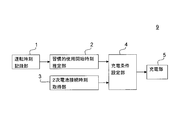
- the charging device 9 shown in FIG. 1 is a charging device for charging a secondary battery mounted on a vehicle such as an electric vehicle or a hybrid vehicle, and includes a driving time recording unit 1, a habitual use start time estimation unit 2 and The secondary battery connection time acquiring unit 3, the charging condition setting unit 4, and the charging unit 5 are provided.
- the term "secondary battery” simply refers to the one to be charged by the charging device 9.
- car simply speaking "car” refers to one on which the secondary battery is mounted.
- the charging device 9 may be mounted on a car, or may not be mounted on a car. In the case where the charging device 9 is mounted on a car, the charging device 9 performs charging in a state where the secondary battery is mounted on the car. On the other hand, in the case where the charging device 9 is not mounted on a car, the secondary battery may be removed from the car and then charging may be performed by the charging device 9. Charging may be performed by the charging device 9 as it is.
- the driving time recording unit 1 records the driving start time and the driving end time of the vehicle in the year, month, day (hour unit), and outputs the recorded driving time to the habitual use start time estimation unit 2.
- the driving time recording unit 1 determines the driving time based on, for example, the state of an ignition key of a car, the state of a car navigation system mounted on the car, or the remaining amount of a secondary battery.
- the operation time is determined based on the state of the ignition key
- the time when the ignition key is switched from OFF to ON is defined as the operation start time
- the time when the ignition key is switched from ON to OFF is defined as the operation end time.
- the driving time is determined based on the state of the car navigation system
- the time when the car navigation system is started is set as the driving start time
- the time when the car navigation system is stopped is set as the driving end time.
- the operation start time When the operation time is determined based on the remaining amount of the secondary battery, the time when the amount of decrease per unit time of the remaining amount of the secondary battery exceeds a fixed threshold is taken as the operation start time. Further, the time at the time when the predetermined time has elapsed when the remaining amount of the secondary battery does not change in the predetermined time after the start of the operation is taken as the operation end time.
- the driving time recording unit 1 it is desirable to store a pair of the driving start time and the driving finish time obtained as described above for about one year.
- the habitual use start time estimation unit 2 customarily uses the secondary battery (in this embodiment, it synchronizes with the operation of the vehicle based on the combination of the drive start time and the drive end time received from the drive time recording unit 1 It estimates the time (the habitual use start time) T EF at which the) is started, and outputs the estimated custom use start time TEF to the charge condition setting unit 4.
- the habitual use start time estimation unit 2 estimates the habitual use start time on a daily basis, a weekly basis, or a monthly basis.
- the habitual use start time on a daily basis for example, superimposes the operation start time for each day, and is set as the operation start time which is overlapped by K days or more in one week.
- K is a fixed value determined experimentally.
- the habitual use start time on a weekly basis is, for example, overlapping the drive start time for each specific day of the week, and is set as the drive start time overlapping for L days or more in one month.
- L is a fixed value obtained experimentally.
- the custom usage start time on a monthly basis is, for example, overlapping the operation start times for each specific day, and is set to an operation start time that overlaps M days or more in one year.
- M is a fixed value obtained experimentally.
- the driving time recording unit 1 may record only the driving start time without recording the driving end time.
- the charging device 9 is connected to a power source (for example, a commercial power source), and when the battery pack including the secondary battery is connected to the charging device 9 (that is, charging is possible) At time t), the information on the time (secondary battery connection time) TSI at that time is output to the charge condition setting unit 4.
- the secondary battery connection time TSI can be regarded as the time when charging of the secondary battery by the charging device 9 becomes possible.
- Charge condition setting unit 4 as described above, habitual use start time estimation unit 2 habitual use start time from T EF are inputted from the secondary battery connection time acquisition unit 3 secondary battery connection time T SI is input Ru.
- the charging condition setting unit 4 sets the charging condition of the secondary battery based on each input information, and outputs the setting to the charging unit 5.
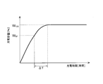
- the battery pack connected to the charging device 9 includes a memory, and in the memory, a charging characteristic that represents the relationship between the charging time and the charging capacity of the secondary battery in the battery pack (see FIG. 2) ) Is recorded in advance.
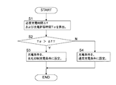
- the charge condition setting unit 4 reads data of the charge characteristic from the memory to set the charge condition. An example of the method of setting the charging condition will be described below with reference to the flowchart shown in FIG.
- Charge condition setting unit 4 calculates the time (necessary charge time) ⁇ T required to charge the secondary battery from current charge capacity WSF to full charge capacity W 100 based on the data of the charge characteristic of the secondary battery. . Further charge condition setting unit 4 also from the secondary battery connection time T SI, recent habitual use start time T EF Time to (charge allowable time) is calculated T [alpha (step S1).
- the charging condition is immediately set when charging is possible, and charging is started. Therefore the secondary battery connection time T SI can be equate when a (beginning of charging) that charging begins.
- charge condition setting unit 4 determines whether or not charge allowable time T ⁇ exceeds necessary charge time ⁇ T (step S2). If the charge allowable time T ⁇ exceeds the required charge time ⁇ T (Y in step S2), a time margin for full charge before the time when it is estimated that the use of the secondary battery will start next It can be said that there is (hereinafter sometimes referred to as "time margin for charging"). In this case, the charge condition setting unit 4 sets the charge condition as the deterioration suppression charge condition (step S3).
- the degradation suppression charge condition every time the temperature of the secondary battery reaches the charge limit temperature C T during charging, so that the pause of charging (a predetermined period (pause) operating to stop charging) is performed It is a charge condition to be used. According to this charging condition, it is possible to stop the temperature rise of the secondary battery due to charging during temporary suspension, and to lower the temperature of the secondary battery by heat radiation. As a result, the secondary battery can be charged so as not to reach a high temperature as compared with the case where temporary suspension is not performed, and the deterioration of the secondary battery can be suppressed.
- the charge limit temperature C T (preset threshold value) can be determined by various methods using experimental results and the like so that the secondary battery is fully charged at least within the charge allowable time T ⁇ . As an example, using the following equation (1), it is possible to calculate the charging limit temperature C T.
- C T C 1 -C 2 ⁇ (T ⁇ - ⁇ T) (1)
- C1 and C2 are fixed values determined by experiment or the like.
- charge limiting temperature C T is set according to the difference between the charge allowable time T ⁇ and the required charging time [Delta] T. More specifically, the charge limit temperature CT is set lower as the difference between the charge allowable time T ⁇ and the required charge time ⁇ T is larger, that is, as the degree of time margin for charge is larger.
- the charge limiting temperature C T for example it is also possible to have a fixed value in accordance with the characteristics of the secondary battery. Further, the charging suspension period may be, for example, a fixed period, or may be a period until the temperature of the secondary battery falls to a specific value.
- the sum of the temporary suspension periods of charging may be set so as not to exceed the difference between the allowable charging time T ⁇ and the required charging time ⁇ T.
- the charging may not be paused. In this way, the secondary battery can be fully charged within the allowable charging time T ⁇ more reliably.
- the charging condition setting unit 4 sets the charging condition to the normal charging condition (step S4).
- the normal charging condition is a charging condition in which no pause is made during charging.
- the charging condition setting unit 4 sets the charging condition to the normal charging condition, and charging proceeds as fast as possible (the next estimated use of the secondary battery is started By time, as close as possible to full charge).
- the charging unit 5 When the charging condition is set by the charging condition setting unit 4, the charging unit 5 immediately starts charging according to the charging condition.
- charging is performed with a constant current until the voltage of the secondary battery reaches a predetermined fixed voltage V CV, and after reaching, charging is performed with a constant voltage (so-called constant current constant).
- V CV voltage of the secondary battery
- constant current constant a constant voltage
- the voltage charging method is adopted, other methods may be adopted.
- the charging unit 5 includes means for detecting the temperature of the secondary battery (for example, a temperature sensor or the like arranged to be in contact with the secondary battery in a state where the secondary battery is connected to the charging device 9) It is possible to monitor the temperature of the secondary battery.
- the charging unit 5 also includes means for detecting the voltage of the secondary battery, and can monitor the voltage of the secondary battery.
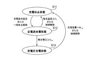
- FIG. 4 shows a state transition diagram of the charging unit 5 when the charging condition is set to the degradation suppressing charging condition.
- the charging unit 5 is in a state in which charging is paused (charging pause state S11).
- the charging unit 5 charges the secondary battery with a constant current (constant current (constant current) Transition to the charge state S12).
- the charging unit 5 transitions to the charging hibernation S11 (in this case, pause). Then, when a predetermined time passes after the temporary suspension state, the temporary suspension is canceled, and the charging unit 5 transitions to the constant current charging state S12.
- charging unit 5 transitions to a state of charging the secondary battery with constant voltage (constant voltage charging state S13). Thereafter, when the charging capacity of the secondary battery reaches the full charging capacity W 100 , the charging unit 5 transitions to the charging suspension state S11 (in this case, the charging is completed). When the connection between the charging device 9 and the secondary battery is canceled in the constant current charging state S12 or the constant voltage charging state S13, the charging unit 5 is in the charging pause state S11 (in this case, the charging is stopped). Transition to
- the charging device 9 charges the secondary battery according to the deterioration suppression charging condition when there is a time allowance for charging, so charging is performed without performing the temporary pause regardless of the presence or absence of the time allowance for charging. It is possible to charge the secondary battery so as not to have a high temperature as compared with a charging device of a specification to be advanced (hereinafter referred to as a “general specification” for convenience).
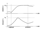
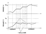
- FIGS. 5 and 6 graphs showing an example of changes in charge capacity and temperature of the secondary battery are shown in FIGS. 5 and 6.
- FIG. 5 is a graph of the charging device of the general specification
- FIG. 6 is a graph of the charging device 9 of the present embodiment.
- the graph indicated by a broken line in FIG. 6 represents a part of the graph shown in FIG. 5 for the purpose of comparison.
- the upper graph shows the change in charge capacity
- the lower graph shows the change in temperature of the secondary battery.
- various conditions in both graphs are assumed to be equal.
- the charging device 9 of this embodiment As shown in FIG. 6, from the time of start of charging until the charging capacity reaches full charge capacity W 100, pause whenever the temperature of the secondary battery reaches the charge limit temperature C T Charging is carried out while (corresponding to the colored portion in FIG. 6) is made. As a result, the temperature of the secondary battery, lowers each time a pause is made, even during peak suppressed to the charging limit temperature C T.
- the temperature (especially peak temperature) of the secondary battery when charged by the charging device 9 of the present embodiment is lower than the temperature of the secondary battery when charged by the charging device of the general specification, It is much lower. Therefore, according to the charging device 9 of the present embodiment, it is possible to charge the secondary battery so as to suppress deterioration as compared with the charging device of the general specification.
- the time when the secondary battery reaches the full charge capacity is later than the charging by the charging device of the general specification.
- prior to habitual use start time T EF can be a full charge capacity secondary batteries, also from habitual use start time T EF a previous point in time Therefore, the possibility of starting to use the secondary battery is low. Therefore, as described above, even if the time for the full charge capacity of the secondary battery is late, there is a low possibility that the secondary battery will not be fully charged before the next use, which is a big problem. It can be said that it is impossible.
- the charging device 9 charges secondary batteries for various uses, such as secondary batteries used for a large storage battery, in addition to secondary batteries used for an on-vehicle power supply device. Can be configured to In addition, it is possible to configure a power storage device or a power supply device using a secondary battery (for example, a secondary battery used for a large storage battery) charged by the charging device 9.
- a secondary battery for example, a secondary battery used for a large storage battery
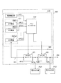
- FIG. 7 is a block diagram showing the configuration of the power supply device 400 according to the second embodiment.
- the power supply device 400 includes a power storage device 410 and a power conversion device (power conversion unit) 420.
- the power storage device 410 includes a battery unit 411 composed of m secondary batteries 200 [1] to 200 [m] (sometimes collectively referred to as “secondary battery 200”), a main controller 412, and a current detection unit. And 413.
- m is an integer of 2 or more. However, m may be 1.
- Each of the secondary batteries 200 [1] to 200 [m] is a secondary battery charged by the charging device 9 of the first embodiment.
- the secondary batteries 200 [1] to 200 [m] are charged by different charging devices 9, but one charging device 9 charges a plurality of secondary batteries 200. It does not matter.
- one charging device 9 may be configured to charge all the secondary batteries 200 (in other words, to charge the battery unit 411).
- the secondary batteries 200 [1] to 200 [m] are connected in series or in parallel with one another. In this example, it is assumed that the secondary batteries 200 [1] to 200 [m] are connected in series with each other. Of the secondary batteries 200 [1] to 200 [m], the negative electrode (negative output terminal) having the lowest potential and the positive electrode (positive output terminal) having the highest potential are converted via the power line 431. It is connected to the device 420.
- the current detection unit 413 detects the value of the current flowing through the power line 431, that is, the current between the battery unit 411 and the power conversion device 420, and outputs the detected current value to the main controller 412.
- the power converter 420 includes a DC / DC converter 421 and a DC / AC converter 422.
- the DC / DC converter 421 includes input / output terminals 421a and 421b
- the DC / AC converter 422 includes input / output terminals 422a and 422b.
- the input / output terminal 421 a of the DC / DC converter 421 is connected to the battery system unit 411 via the power line 431.
- the input / output terminals 421b and 422a are connected to each other and to the power output unit PU1.
- the input / output terminal 422 b can be connected to the power output unit PU 2 and can be connected to a power system 432 which is a power system different from the power supply device 400.
- the connection between the power conversion device 400 and the power output units PU1 and PU2 is not essential.
- the power output units PU1 and PU2 as an example of the external device include outlets. For example, various loads are connected to the power output units PU1 and PU2. It may be considered that each of the power output units PU1 and PU2 is a load.
- Power system 432 includes a commercial power source or a solar cell. It is also possible to connect a solar cell to the input / output terminal 421b, and in this case, a DC voltage based on power generation of the solar cell can be supplied to the input / output terminal 421b.
- an AC output unit (AC output unit) of the power conditioner can be connected to the input / output terminal 422b.
- the power converter 420 uses the DC / DC converter 421 and the DC / AC converter 422 under the control of the main controller 412, and the secondary batteries 200 [1] to 200 [m], and the power output units PU1 and PU2 or the power Power conversion is performed between the system 432 and the system.
- the main controller 412 controls the DC / DC converter 421 and the DC / AC converter 422 based on the detected current value by the current detection unit 413, etc., to charge each of the secondary batteries 200 [1] to 200 [m]. And control the discharge. However, the main controller 412 may control only charging or discharging of each of the secondary batteries 200 [1] to 200 [m].
- the main controller 412 is configured to receive, for each of the secondary batteries 200 [1] to 200 [m], a signal (status signal ST) related to the status of the secondary battery based on the detected value of the output voltage or the like. It is good. That is, for example, devices for generating the state signal ST may be prepared for each secondary battery 200, and these devices may send the state signal ST to the main controller 412. In this case, the main controller 412 receives each of the status signals ST [i] for the secondary battery 200 [i] (where i is an integer of 1 to m).
- the status signal ST includes, for example, a charge permission signal indicating permission of charging the secondary battery 200, a charge inhibition signal indicating prohibition of charging the secondary battery 200, a discharge permission signal indicating permission of discharging the secondary battery 200, and the secondary A discharge inhibition signal indicating discharge inhibition of the battery 200 is included.
- the state signal ST further includes a charge request signal requesting charge of the secondary battery 200 and a discharge request signal requesting discharge of the secondary battery 200, as necessary.
- the main controller 412 charges and / or discharges each of the secondary batteries 200 [1] to 200 [m] based on the state signal ST in addition to the current value detected by the current detection unit 413. May be controlled.
- DC / DC converter 421 controls secondary battery 200 [under the control of main controller 412]. 1] to 200 [m] output DC power of the battery unit 411 based on the output power is converted to other DC power and the other DC power is output from the input / output terminal 421b, and the DC / AC converter 422 The DC power from the terminal 421b is converted into AC power, and the AC power is output from the input / output terminal 422b.
- the DC / AC converter 422 controls the power system 432 under the control of the main controller 412. Converts the AC power from DC into DC power and outputs the DC power from the input / output terminal 422a, and the DC / DC converter 421 converts DC power from the input / output terminal 422a into other DC power and The DC power is output from the input / output terminal 421a.
- each of the secondary batteries 200 [1] to 200 [m] is charged by the DC power from the input / output terminal 421a.
- the main controller 412 is an example of a charge / discharge control unit that performs control regarding charging or discharging of the secondary battery 200 [1] to 200 [m]. Further, the main controller 412 has a function of detecting the output voltage value of each of the secondary batteries 200, and based on the detection result, determines whether or not to charge or discharge the secondary battery 200. Then, the power converter 420 may be controlled according to the determination result.
- the power storage device 410 and the power supply device 400 are formed such that the battery unit 411 includes only one secondary battery 200 (for example, the secondary battery 200 [1]). It does not matter.
- the use of the secondary battery 200 charged by the charging device 9 may be more advantageous.
- the shortage of the charge capacity of the secondary battery 200 can be more reliably prevented.
- the power stored in the secondary battery 200 can be used for more applications.
- the charging device 9 has a functional unit (estimating unit) for estimating the habitual use start time TEF of the secondary battery based on the usage history of the secondary battery, and the secondary battery connection.
- time T SI time from (charging start time of the secondary battery) to the nearest use start time T EF, functional unit that calculates the charge allowable time T ⁇ (the allowable charge time calculation unit), a fully charged secondary battery
- the functional unit calculates the required charging time as required charging time ⁇ T (required charging time calculation unit), and when the charging allowable time T ⁇ does not exceed the required charging time ⁇ T, the secondary battery is normally charged under the charging conditions.
- the functional unit (charging execution unit) for charging the secondary battery under the deterioration suppression charging condition is provided.
- the deterioration suppressing charging condition is a condition for charging the secondary battery so as to temporarily suspend charging during charging and to be fully charged within the charging allowable time T ⁇ . Therefore, according to the charging device 9, while it is possible to charge the secondary battery so as to suppress deterioration, it is possible to avoid as much as possible the situation where the secondary battery is not sufficiently charged by the next use. Is possible.
- the habitual use start time of the secondary battery is estimated based on the usage history of the secondary battery, and the charge allowable time and the like are calculated based on the estimation result. Therefore, it is possible to perform charging under the deterioration suppression charging condition without requiring the user to do so (without requiring the user to input the time to use the secondary battery next).
- the charging object of the charging device and the charging method according to the present invention is not limited to a lithium ion battery, and can be applied to any secondary battery in which storage deterioration may occur.
- the secondary battery which is a charge object of the charging device and charging method which concern on this invention is not limited to the thing for vehicle mounting.
- the charge characteristic representing the relationship between the charge time of the secondary battery and the charge capacity is stored in the memory included in the battery pack, but charging of the secondary battery to be charged on the charging device side
- a charge characteristic representing a relationship between time and charge capacity may be stored in advance.
- the charge device since the charge characteristic representing the relationship between the charge time of the secondary battery and the charge capacity changes along with the use of the secondary battery, the charge device according to the present invention is provided with a learning function for changes in the charge characteristic. It is also good. For example, the stored contents related to the charging characteristic may be rewritten according to the usage history of the secondary battery, or the stored charging characteristic may be corrected and used.
- the present invention can be used for a charging device for charging a secondary battery.
Landscapes
- Engineering & Computer Science (AREA)
- Power Engineering (AREA)
- Transportation (AREA)
- Mechanical Engineering (AREA)
- Life Sciences & Earth Sciences (AREA)
- Sustainable Development (AREA)
- Sustainable Energy (AREA)
- Chemical & Material Sciences (AREA)
- Manufacturing & Machinery (AREA)
- Chemical Kinetics & Catalysis (AREA)
- Electrochemistry (AREA)
- General Chemical & Material Sciences (AREA)
- Secondary Cells (AREA)
- Charge And Discharge Circuits For Batteries Or The Like (AREA)
- Electric Propulsion And Braking For Vehicles (AREA)
- Supply And Distribution Of Alternating Current (AREA)
Abstract
Description
[充電装置の構成および使用形態の概略]
本発明の一実施形態(第1実施形態)に係る充電装置の構成を図1に示す。図1に示す当該充電装置9は、電気自動車やハイブリッド車などの自動車に搭載される2次電池を充電する充電装置であって、運転時刻記録部1と、習慣的使用開始時刻推定部2と、2次電池接続時刻取得部3と、充電条件設定部4と、充電部5とを備えている。なお以降、単に「2次電池」といえば、充電装置9の充電対象であるものを指す。また単に「自動車」といえば、当該2次電池が搭載されるものを指す。
運転時刻記録部1は、自動車の運転開始時刻と運転終了時刻を年月日時(時間単位)で記録し、その記録した運転時刻を習慣的使用開始時刻推定部2に出力する。運転時刻記録部1は、例えば、自動車のイグニッションキーの状態、自動車に搭載されたカーナビゲーションシステムの状態、または2次電池の残量などに基づいて運転時刻を判断する。
習慣的使用開始時刻推定部2は、運転時刻記録部1から受け取った運転開始時刻と運転終了時刻の組に基づいて、習慣的に2次電池の使用(本実施形態では自動車の運転と同期する)が開始される時刻(習慣的使用開始時刻)TEFを推定し、その推定した習慣的使用開始時刻TEFを充電条件設定部4に出力する。
2次電池接続時刻取得部3は、充電装置9が電源(例えば商用電源)に接続されており、かつ、充電装置9に2次電池を含む電池パックが接続された時点(すなわち、充電が可能となった時点)で、そのときの時刻(2次電池接続時刻)TSIの情報を充電条件設定部4に出力する。なお2次電池接続時刻TSIは、充電装置9による2次電池の充電が可能となった時刻と見ることが出来る。
充電条件設定部4は、上述の通り、習慣的使用開始時刻推定部2から習慣的使用開始時刻TEFが入力され、2次電池接続時刻取得部3から2次電池接続時刻TSIが入力される。充電条件設定部4は、2次電池接続時刻TSIが入力された時点で、入力された各情報に基づいて2次電池の充電条件を設定し、充電部5に出力する。
CT=C1-C2×(Tα-ΔT)・・・(1)
但し、C1およびC2は、実験等によって求めた固定値とする。
充電部5は、充電条件設定部4によって充電条件が設定されると、この充電条件に従って直ちに充電を開始する。なお本実施形態では、充電の基本方式として、2次電池の電圧が所定の固定電圧VCVに達するまでは定電流で充電し、達した後は定電圧で充電する方式(いわゆる、定電流定電圧の充電方式)を採用するが、他の方式が採用されても構わない。
上述した通り充電装置9は、充電の時間的余裕がある場合には、劣化抑制充電条件によって2次電池を充電するため、充電の時間的余裕の有無に関わらず一時休止を行わずに充電を進める仕様(以下、便宜的に「一般的仕様」と称する)の充電装置に比べて、2次電池を高温とならないように充電することが可能である。
第1実施形態に係る充電装置9は、車載用の電源装置に用いられる2次電池の他、例えば、大型の蓄電池に用いられる2次電池など、各種用途の2次電池を充電するように構成され得る。また充電装置9によって充電される2次電池(例えば、大型の蓄電池に用いられる2次電池)を用いて、電力貯蔵装置や電源装置を構成することが可能である。
以上までに説明した通り、充電装置9は、2次電池の使用履歴に基づいて、2次電池の習慣的な使用開始時刻TEFを推定する機能部(推定部)と、2次電池接続時刻TSI(2次電池の充電開始時)から直近の使用開始時刻TEFまでの時間を、充電許容時間Tαとして算出する機能部(充電許容時間算出部)と、2次電池を満充電とするのに要する充電時間を、必要充電時間ΔTとして算出する機能部(必要充電時間算出部)と、充電許容時間Tαが必要充電時間ΔTを超えないときは、通常充電条件にて2次電池を充電する一方、充電許容時間Tαが必要充電時間ΔTを超えるときは、劣化抑制充電条件にて2次電池を充電する機能部(充電実行部)と、を備えている。
2 習慣的使用開始時刻推定部
3 2次電池接続時刻取得部
4 充電条件設定部
5 充電部
9 充電装置
200 2次電池
400 電源装置
410 電力貯蔵装置
411 電池ユニット
412 メインコントローラ
413 電流検出部
420 電力変換装置
421 DC/DCコンバータ
422 DC/ACコンバータ
431 電力線
432 電力系統
Claims (8)
- 2次電池を充電する充電装置であって、
前記2次電池の使用履歴に基づいて、該2次電池の習慣的な使用開始時を推定する推定部と、
前記2次電池の充電開始時から直近の前記使用開始時までの時間を、充電許容時間として算出する充電許容時間算出部と、
前記2次電池を満充電とするのに要する充電時間を、必要充電時間として算出する必要充電時間算出部と、
前記充電許容時間が前記必要充電時間を超えるときに、劣化抑制充電条件にて前記2次電池を充電する充電実行部と、を備え、
前記劣化抑制充電条件は、
充電中に充電の一時休止を行うとともに、前記充電許容時間内に満充電となるように、前記2次電池を充電する条件であることを特徴とする充電装置。 - 前記2次電池の温度を検出する温度検出部を備え、
前記検出された温度が予め設定された閾値に達したときに、前記一時休止を行うことを特徴とする請求項1に記載の充電装置。 - 前記閾値は、
前記充電許容時間と前記必要充電時間の差に応じて設定されることを特徴とする請求項2に記載の充電装置。 - 前記充電の一時休止の期間の合計は、前記充電許容時間と前記必要充電時間の差を越えないように設定されることを特徴とする請求項2に記載の充電装置。
- 前記2次電池は、自動車に搭載される電池であることを特徴とする請求項1から請求項4の何れかに記載の充電装置。
- 前記推定部は、
前記自動車のイグニッションキーの状態、前記自動車に搭載されたカーナビゲーションシステムの状態、または前記2次電池の残量に基づいて、前記使用履歴の情報を蓄積することを特徴とする請求項5に記載の充電装置。 - 請求項1に記載の充電装置によって充電される前記2次電池と、
前記2次電池の充電又は放電に関する制御を行う充放電制御ユニットと、を備えたことを特徴とする電力貯蔵装置。 - 請求項7に記載の電力貯蔵装置と、
前記充放電制御ユニットの制御の下で、前記2次電池と外部機器又は電力系統との間における電力変換を行う電力変換装置と、を備え、
前記外部機器又は前記電力系統と接続可能であることを特徴とする電源装置。
Priority Applications (3)
| Application Number | Priority Date | Filing Date | Title |
|---|---|---|---|
| CN201180048667.3A CN103155347B (zh) | 2010-12-13 | 2011-12-02 | 充电设备、电力存储设备以及电源设备 |
| JP2012548731A JP5891441B2 (ja) | 2010-12-13 | 2011-12-02 | 充電装置、電力貯蔵装置、および電源装置 |
| US13/824,922 US9252622B2 (en) | 2010-12-13 | 2011-12-02 | Charging apparatus, power storage apparatus, and power source apparatus |
Applications Claiming Priority (2)
| Application Number | Priority Date | Filing Date | Title |
|---|---|---|---|
| JP2010276546 | 2010-12-13 | ||
| JP2010-276546 | 2010-12-13 |
Publications (1)
| Publication Number | Publication Date |
|---|---|
| WO2012081423A1 true WO2012081423A1 (ja) | 2012-06-21 |
Family
ID=46244532
Family Applications (1)
| Application Number | Title | Priority Date | Filing Date |
|---|---|---|---|
| PCT/JP2011/077910 Ceased WO2012081423A1 (ja) | 2010-12-13 | 2011-12-02 | 充電装置、電力貯蔵装置、および電源装置 |
Country Status (4)
| Country | Link |
|---|---|
| US (1) | US9252622B2 (ja) |
| JP (1) | JP5891441B2 (ja) |
| CN (1) | CN103155347B (ja) |
| WO (1) | WO2012081423A1 (ja) |
Cited By (5)
| Publication number | Priority date | Publication date | Assignee | Title |
|---|---|---|---|---|
| US10539204B2 (en) | 2014-09-24 | 2020-01-21 | Itt Manufacturing Enterprises Llc | Damping and support device for electrical equipments |
| JP2021078303A (ja) * | 2019-11-12 | 2021-05-20 | 東芝三菱電機産業システム株式会社 | エネルギーマネジメントシステム |
| JP2021126036A (ja) * | 2020-02-06 | 2021-08-30 | 株式会社デンソー | 車両の充電システム |
| JP2021164357A (ja) * | 2020-04-02 | 2021-10-11 | 株式会社Subaru | 車両 |
| US11660973B2 (en) | 2019-12-04 | 2023-05-30 | Toyota Jidosha Kabushiki Kaisha | Charging system, vehicle, charging method, and control device |
Families Citing this family (10)
| Publication number | Priority date | Publication date | Assignee | Title |
|---|---|---|---|---|
| US8981727B2 (en) * | 2012-05-21 | 2015-03-17 | General Electric Company | Method and apparatus for charging multiple energy storage devices |
| US9731617B2 (en) * | 2014-12-04 | 2017-08-15 | Ford Global Technologies, Llc | Pattern based charge scheduling |
| JP6686395B2 (ja) * | 2015-12-01 | 2020-04-22 | オムロン株式会社 | バッテリ充電装置、バッテリ充電システムおよびバッテリ充電方法 |
| JP2018152285A (ja) | 2017-03-14 | 2018-09-27 | 株式会社東芝 | 蓄電池パック |
| US11658503B2 (en) * | 2017-07-31 | 2023-05-23 | Nissan Motor Co., Ltd. | Charging time computation method and charge control device |
| KR102544462B1 (ko) | 2018-01-25 | 2023-06-19 | 삼성전자 주식회사 | 배터리를 포함하는 전자 장치 및 이의 충전구간을 제어하는 방법 |
| JP7098981B2 (ja) * | 2018-03-16 | 2022-07-12 | ソニーグループ株式会社 | 電子機器、充電制御方法及びコンピュータプログラム |
| US11862772B2 (en) * | 2018-03-29 | 2024-01-02 | Canal Electronics LLC | User-defined battery recharging systems and methods |
| JP6713030B2 (ja) * | 2018-10-12 | 2020-06-24 | 本田技研工業株式会社 | 診断システム、診断方法、及びプログラム |
| KR102710751B1 (ko) | 2019-02-28 | 2024-09-27 | 삼성전자주식회사 | 배터리의 충전을 제어하는 방법 및 그 방법을 적용한 전자 장치 |
Citations (3)
| Publication number | Priority date | Publication date | Assignee | Title |
|---|---|---|---|---|
| JP2009136109A (ja) * | 2007-11-30 | 2009-06-18 | Toyota Motor Corp | 充電制御装置および充電制御方法 |
| WO2009090913A1 (ja) * | 2008-01-14 | 2009-07-23 | Toyota Jidosha Kabushiki Kaisha | リチウムイオン二次電池の充電方法、及び、ハイブリッド自動車 |
| JP2010154646A (ja) * | 2008-12-25 | 2010-07-08 | Omron Corp | 充電制御装置および方法、並びに、プログラム |
Family Cites Families (19)
| Publication number | Priority date | Publication date | Assignee | Title |
|---|---|---|---|---|
| JP2732204B2 (ja) * | 1993-09-29 | 1998-03-25 | 株式会社ジップチャージ | 二次電池の高速充電方法及びその装置 |
| JP3232912B2 (ja) * | 1994-09-29 | 2001-11-26 | 株式会社豊田自動織機 | 充電装置 |
| JPH09168240A (ja) * | 1995-12-12 | 1997-06-24 | Toyota Motor Corp | バッテリ充電装置 |
| JPH10215525A (ja) | 1996-12-25 | 1998-08-11 | Oki Electric Ind Co Ltd | 充電装置 |
| EP1050944A4 (en) * | 1998-10-15 | 2007-10-17 | Yamaha Motor Co Ltd | POWER GENERATION SYSTEM FOR AN ELECTRIC VEHICLE |
| JP2002142378A (ja) * | 2000-10-31 | 2002-05-17 | Canon Inc | 充電装置、方法及び記憶媒体 |
| JP2006115654A (ja) * | 2004-10-18 | 2006-04-27 | Nec Corp | 充電制御回路、充電制御方法、及び該充電制御回路が設けられた電子機器 |
| JP5168891B2 (ja) | 2006-11-28 | 2013-03-27 | 日産自動車株式会社 | 電動車両充電電力マネジメントシステム |
| JP2008204811A (ja) | 2007-02-20 | 2008-09-04 | Mitsumi Electric Co Ltd | 半導体装置 |
| JP4798087B2 (ja) * | 2007-07-10 | 2011-10-19 | トヨタ自動車株式会社 | 電力システムおよびそれを備えた車両 |
| JP4969547B2 (ja) * | 2008-10-14 | 2012-07-04 | トヨタ自動車株式会社 | 制御装置及び充電制御方法 |
| JP4932810B2 (ja) | 2008-10-20 | 2012-05-16 | マツダ株式会社 | 電動車両用バッテリの充電方法およびその装置 |
| CN101789621A (zh) * | 2009-01-23 | 2010-07-28 | 华硕电脑股份有限公司 | 充电装置 |
| JP2010183789A (ja) | 2009-02-09 | 2010-08-19 | Toyota Motor Corp | 車両搭載用充電装置 |
| US10189359B2 (en) | 2009-02-17 | 2019-01-29 | Chargepoint, Inc. | Transmitting notification messages for an electric vehicle charging network |
| EP2404802A1 (en) * | 2009-03-06 | 2012-01-11 | Toyota Jidosha Kabushiki Kaisha | Hybrid vehicle control device and control method |
| US8963504B2 (en) * | 2009-08-11 | 2015-02-24 | Sony Corporation | Electronic device, method of charging electronic device, program, charging control apparatus, and charging control method |
| JP5353580B2 (ja) * | 2009-09-08 | 2013-11-27 | 株式会社デンソー | 充電状態表示装置および電力供給制御装置 |
| US8583309B2 (en) * | 2009-11-13 | 2013-11-12 | Toyota Jidosha Kabushiki Kaisha | Hybrid vehicle and control method of hybrid vehicle |
-
2011
- 2011-12-02 US US13/824,922 patent/US9252622B2/en not_active Expired - Fee Related
- 2011-12-02 JP JP2012548731A patent/JP5891441B2/ja not_active Expired - Fee Related
- 2011-12-02 CN CN201180048667.3A patent/CN103155347B/zh not_active Expired - Fee Related
- 2011-12-02 WO PCT/JP2011/077910 patent/WO2012081423A1/ja not_active Ceased
Patent Citations (3)
| Publication number | Priority date | Publication date | Assignee | Title |
|---|---|---|---|---|
| JP2009136109A (ja) * | 2007-11-30 | 2009-06-18 | Toyota Motor Corp | 充電制御装置および充電制御方法 |
| WO2009090913A1 (ja) * | 2008-01-14 | 2009-07-23 | Toyota Jidosha Kabushiki Kaisha | リチウムイオン二次電池の充電方法、及び、ハイブリッド自動車 |
| JP2010154646A (ja) * | 2008-12-25 | 2010-07-08 | Omron Corp | 充電制御装置および方法、並びに、プログラム |
Cited By (8)
| Publication number | Priority date | Publication date | Assignee | Title |
|---|---|---|---|---|
| US10539204B2 (en) | 2014-09-24 | 2020-01-21 | Itt Manufacturing Enterprises Llc | Damping and support device for electrical equipments |
| JP2021078303A (ja) * | 2019-11-12 | 2021-05-20 | 東芝三菱電機産業システム株式会社 | エネルギーマネジメントシステム |
| JP7259709B2 (ja) | 2019-11-12 | 2023-04-18 | 東芝三菱電機産業システム株式会社 | エネルギーマネジメントシステム |
| US11660973B2 (en) | 2019-12-04 | 2023-05-30 | Toyota Jidosha Kabushiki Kaisha | Charging system, vehicle, charging method, and control device |
| JP2021126036A (ja) * | 2020-02-06 | 2021-08-30 | 株式会社デンソー | 車両の充電システム |
| JP7435332B2 (ja) | 2020-02-06 | 2024-02-21 | 株式会社デンソー | 車両の充電システム |
| JP2021164357A (ja) * | 2020-04-02 | 2021-10-11 | 株式会社Subaru | 車両 |
| JP7453834B2 (ja) | 2020-04-02 | 2024-03-21 | 株式会社Subaru | 車両 |
Also Published As
| Publication number | Publication date |
|---|---|
| US20130249483A1 (en) | 2013-09-26 |
| JPWO2012081423A1 (ja) | 2014-05-22 |
| JP5891441B2 (ja) | 2016-03-23 |
| US9252622B2 (en) | 2016-02-02 |
| CN103155347B (zh) | 2015-06-24 |
| CN103155347A (zh) | 2013-06-12 |
Similar Documents
| Publication | Publication Date | Title |
|---|---|---|
| JP5891441B2 (ja) | 充電装置、電力貯蔵装置、および電源装置 | |
| JP5267675B2 (ja) | 車両の充電システムおよびそれを備える電動車両 | |
| JP5782803B2 (ja) | 電池の充電装置および電池の充電方法 | |
| US8237398B2 (en) | Electric system, charging device and charging method for electric system for discharging of a power storage mechanism for resetting a state of a charge | |
| JP6822300B2 (ja) | 充電率推定方法および車載の電池システム | |
| CN103389466B (zh) | 蓄电元件管理装置、蓄电元件包、记录介质及soc推测方法 | |
| CN105745116B (zh) | 电动车的蓄电系统 | |
| US8159186B2 (en) | Power source system, power supply control method for the power source system, power supply control program for the power source system, and computer-readable recording medium with the power supply control program recorded thereon | |
| WO2012010955A2 (en) | Vehicle control device and vehicle control method | |
| WO2015129117A1 (ja) | 二次電池のsoc推定装置 | |
| CN103620911A (zh) | 二次电池的充电控制装置以及充电控制方法 | |
| CN102458901A (zh) | 电池充放电控制装置 | |
| CN104364116A (zh) | 蓄电系统和均衡方法 | |
| JP2017129409A (ja) | 二次電池の制御システム | |
| JP2012244663A (ja) | 電気自動車の充電システム | |
| JP6186248B2 (ja) | インバータの異常判定装置 | |
| JP5989320B2 (ja) | 車両用制御装置および残容量推定方法 | |
| JP2005261034A (ja) | 蓄電機構の制御装置 | |
| WO2011059025A1 (ja) | 充電装置及び充電方法 | |
| CN110239565A (zh) | 电动车辆及电动车辆的控制方法 | |
| JP5867373B2 (ja) | 電池システムおよび、リチウムイオン二次電池の内部抵抗の推定方法 | |
| JP6459864B2 (ja) | バッテリ制御装置 | |
| JP6183465B2 (ja) | 蓄電システム | |
| JP2013031248A (ja) | バッテリ装置のヒステリシス低減システム | |
| JP2017150975A (ja) | ハイレート劣化指標推定制御装置 |
Legal Events
| Date | Code | Title | Description |
|---|---|---|---|
| WWE | Wipo information: entry into national phase |
Ref document number: 201180048667.3 Country of ref document: CN |
|
| 121 | Ep: the epo has been informed by wipo that ep was designated in this application |
Ref document number: 11849712 Country of ref document: EP Kind code of ref document: A1 |
|
| ENP | Entry into the national phase |
Ref document number: 2012548731 Country of ref document: JP Kind code of ref document: A |
|
| WWE | Wipo information: entry into national phase |
Ref document number: 13824922 Country of ref document: US |
|
| NENP | Non-entry into the national phase |
Ref country code: DE |
|
| 122 | Ep: pct application non-entry in european phase |
Ref document number: 11849712 Country of ref document: EP Kind code of ref document: A1 |