US10189359B2 - Transmitting notification messages for an electric vehicle charging network - Google Patents
Transmitting notification messages for an electric vehicle charging network Download PDFInfo
- Publication number
- US10189359B2 US10189359B2 US12/372,726 US37272609A US10189359B2 US 10189359 B2 US10189359 B2 US 10189359B2 US 37272609 A US37272609 A US 37272609A US 10189359 B2 US10189359 B2 US 10189359B2
- Authority
- US
- United States
- Prior art keywords
- charging
- subscriber
- event
- interest
- charging station
- Prior art date
- Legal status (The legal status is an assumption and is not a legal conclusion. Google has not performed a legal analysis and makes no representation as to the accuracy of the status listed.)
- Active, expires
Links
Images


Classifications
-
- B60L11/1816—
-
- B—PERFORMING OPERATIONS; TRANSPORTING
- B60—VEHICLES IN GENERAL
- B60L—PROPULSION OF ELECTRICALLY-PROPELLED VEHICLES; SUPPLYING ELECTRIC POWER FOR AUXILIARY EQUIPMENT OF ELECTRICALLY-PROPELLED VEHICLES; ELECTRODYNAMIC BRAKE SYSTEMS FOR VEHICLES IN GENERAL; MAGNETIC SUSPENSION OR LEVITATION FOR VEHICLES; MONITORING OPERATING VARIABLES OF ELECTRICALLY-PROPELLED VEHICLES; ELECTRIC SAFETY DEVICES FOR ELECTRICALLY-PROPELLED VEHICLES
- B60L53/00—Methods of charging batteries, specially adapted for electric vehicles; Charging stations or on-board charging equipment therefor; Exchange of energy storage elements in electric vehicles
- B60L53/10—Methods of charging batteries, specially adapted for electric vehicles; Charging stations or on-board charging equipment therefor; Exchange of energy storage elements in electric vehicles characterised by the energy transfer between the charging station and the vehicle
- B60L53/14—Conductive energy transfer
-
- B60L11/184—
-
- B60L11/1842—
-
- B60L11/1844—
-
- B60L11/1846—
-
- B60L11/1848—
-
- B—PERFORMING OPERATIONS; TRANSPORTING
- B60—VEHICLES IN GENERAL
- B60L—PROPULSION OF ELECTRICALLY-PROPELLED VEHICLES; SUPPLYING ELECTRIC POWER FOR AUXILIARY EQUIPMENT OF ELECTRICALLY-PROPELLED VEHICLES; ELECTRODYNAMIC BRAKE SYSTEMS FOR VEHICLES IN GENERAL; MAGNETIC SUSPENSION OR LEVITATION FOR VEHICLES; MONITORING OPERATING VARIABLES OF ELECTRICALLY-PROPELLED VEHICLES; ELECTRIC SAFETY DEVICES FOR ELECTRICALLY-PROPELLED VEHICLES
- B60L3/00—Electric devices on electrically-propelled vehicles for safety purposes; Monitoring operating variables, e.g. speed, deceleration or energy consumption
- B60L3/0023—Detecting, eliminating, remedying or compensating for drive train abnormalities, e.g. failures within the drive train
- B60L3/0046—Detecting, eliminating, remedying or compensating for drive train abnormalities, e.g. failures within the drive train relating to electric energy storage systems, e.g. batteries or capacitors
-
- B—PERFORMING OPERATIONS; TRANSPORTING
- B60—VEHICLES IN GENERAL
- B60L—PROPULSION OF ELECTRICALLY-PROPELLED VEHICLES; SUPPLYING ELECTRIC POWER FOR AUXILIARY EQUIPMENT OF ELECTRICALLY-PROPELLED VEHICLES; ELECTRODYNAMIC BRAKE SYSTEMS FOR VEHICLES IN GENERAL; MAGNETIC SUSPENSION OR LEVITATION FOR VEHICLES; MONITORING OPERATING VARIABLES OF ELECTRICALLY-PROPELLED VEHICLES; ELECTRIC SAFETY DEVICES FOR ELECTRICALLY-PROPELLED VEHICLES
- B60L3/00—Electric devices on electrically-propelled vehicles for safety purposes; Monitoring operating variables, e.g. speed, deceleration or energy consumption
- B60L3/0023—Detecting, eliminating, remedying or compensating for drive train abnormalities, e.g. failures within the drive train
- B60L3/0069—Detecting, eliminating, remedying or compensating for drive train abnormalities, e.g. failures within the drive train relating to the isolation, e.g. ground fault or leak current
-
- B—PERFORMING OPERATIONS; TRANSPORTING
- B60—VEHICLES IN GENERAL
- B60L—PROPULSION OF ELECTRICALLY-PROPELLED VEHICLES; SUPPLYING ELECTRIC POWER FOR AUXILIARY EQUIPMENT OF ELECTRICALLY-PROPELLED VEHICLES; ELECTRODYNAMIC BRAKE SYSTEMS FOR VEHICLES IN GENERAL; MAGNETIC SUSPENSION OR LEVITATION FOR VEHICLES; MONITORING OPERATING VARIABLES OF ELECTRICALLY-PROPELLED VEHICLES; ELECTRIC SAFETY DEVICES FOR ELECTRICALLY-PROPELLED VEHICLES
- B60L3/00—Electric devices on electrically-propelled vehicles for safety purposes; Monitoring operating variables, e.g. speed, deceleration or energy consumption
- B60L3/12—Recording operating variables ; Monitoring of operating variables
-
- B—PERFORMING OPERATIONS; TRANSPORTING
- B60—VEHICLES IN GENERAL
- B60L—PROPULSION OF ELECTRICALLY-PROPELLED VEHICLES; SUPPLYING ELECTRIC POWER FOR AUXILIARY EQUIPMENT OF ELECTRICALLY-PROPELLED VEHICLES; ELECTRODYNAMIC BRAKE SYSTEMS FOR VEHICLES IN GENERAL; MAGNETIC SUSPENSION OR LEVITATION FOR VEHICLES; MONITORING OPERATING VARIABLES OF ELECTRICALLY-PROPELLED VEHICLES; ELECTRIC SAFETY DEVICES FOR ELECTRICALLY-PROPELLED VEHICLES
- B60L53/00—Methods of charging batteries, specially adapted for electric vehicles; Charging stations or on-board charging equipment therefor; Exchange of energy storage elements in electric vehicles
- B60L53/30—Constructional details of charging stations
- B60L53/305—Communication interfaces
-
- B—PERFORMING OPERATIONS; TRANSPORTING
- B60—VEHICLES IN GENERAL
- B60L—PROPULSION OF ELECTRICALLY-PROPELLED VEHICLES; SUPPLYING ELECTRIC POWER FOR AUXILIARY EQUIPMENT OF ELECTRICALLY-PROPELLED VEHICLES; ELECTRODYNAMIC BRAKE SYSTEMS FOR VEHICLES IN GENERAL; MAGNETIC SUSPENSION OR LEVITATION FOR VEHICLES; MONITORING OPERATING VARIABLES OF ELECTRICALLY-PROPELLED VEHICLES; ELECTRIC SAFETY DEVICES FOR ELECTRICALLY-PROPELLED VEHICLES
- B60L53/00—Methods of charging batteries, specially adapted for electric vehicles; Charging stations or on-board charging equipment therefor; Exchange of energy storage elements in electric vehicles
- B60L53/60—Monitoring or controlling charging stations
- B60L53/63—Monitoring or controlling charging stations in response to network capacity
-
- B—PERFORMING OPERATIONS; TRANSPORTING
- B60—VEHICLES IN GENERAL
- B60L—PROPULSION OF ELECTRICALLY-PROPELLED VEHICLES; SUPPLYING ELECTRIC POWER FOR AUXILIARY EQUIPMENT OF ELECTRICALLY-PROPELLED VEHICLES; ELECTRODYNAMIC BRAKE SYSTEMS FOR VEHICLES IN GENERAL; MAGNETIC SUSPENSION OR LEVITATION FOR VEHICLES; MONITORING OPERATING VARIABLES OF ELECTRICALLY-PROPELLED VEHICLES; ELECTRIC SAFETY DEVICES FOR ELECTRICALLY-PROPELLED VEHICLES
- B60L53/00—Methods of charging batteries, specially adapted for electric vehicles; Charging stations or on-board charging equipment therefor; Exchange of energy storage elements in electric vehicles
- B60L53/60—Monitoring or controlling charging stations
- B60L53/64—Optimising energy costs, e.g. responding to electricity rates
-
- B—PERFORMING OPERATIONS; TRANSPORTING
- B60—VEHICLES IN GENERAL
- B60L—PROPULSION OF ELECTRICALLY-PROPELLED VEHICLES; SUPPLYING ELECTRIC POWER FOR AUXILIARY EQUIPMENT OF ELECTRICALLY-PROPELLED VEHICLES; ELECTRODYNAMIC BRAKE SYSTEMS FOR VEHICLES IN GENERAL; MAGNETIC SUSPENSION OR LEVITATION FOR VEHICLES; MONITORING OPERATING VARIABLES OF ELECTRICALLY-PROPELLED VEHICLES; ELECTRIC SAFETY DEVICES FOR ELECTRICALLY-PROPELLED VEHICLES
- B60L53/00—Methods of charging batteries, specially adapted for electric vehicles; Charging stations or on-board charging equipment therefor; Exchange of energy storage elements in electric vehicles
- B60L53/60—Monitoring or controlling charging stations
- B60L53/65—Monitoring or controlling charging stations involving identification of vehicles or their battery types
-
- B—PERFORMING OPERATIONS; TRANSPORTING
- B60—VEHICLES IN GENERAL
- B60L—PROPULSION OF ELECTRICALLY-PROPELLED VEHICLES; SUPPLYING ELECTRIC POWER FOR AUXILIARY EQUIPMENT OF ELECTRICALLY-PROPELLED VEHICLES; ELECTRODYNAMIC BRAKE SYSTEMS FOR VEHICLES IN GENERAL; MAGNETIC SUSPENSION OR LEVITATION FOR VEHICLES; MONITORING OPERATING VARIABLES OF ELECTRICALLY-PROPELLED VEHICLES; ELECTRIC SAFETY DEVICES FOR ELECTRICALLY-PROPELLED VEHICLES
- B60L53/00—Methods of charging batteries, specially adapted for electric vehicles; Charging stations or on-board charging equipment therefor; Exchange of energy storage elements in electric vehicles
- B60L53/60—Monitoring or controlling charging stations
- B60L53/66—Data transfer between charging stations and vehicles
- B60L53/665—Methods related to measuring, billing or payment
-
- B—PERFORMING OPERATIONS; TRANSPORTING
- B60—VEHICLES IN GENERAL
- B60L—PROPULSION OF ELECTRICALLY-PROPELLED VEHICLES; SUPPLYING ELECTRIC POWER FOR AUXILIARY EQUIPMENT OF ELECTRICALLY-PROPELLED VEHICLES; ELECTRODYNAMIC BRAKE SYSTEMS FOR VEHICLES IN GENERAL; MAGNETIC SUSPENSION OR LEVITATION FOR VEHICLES; MONITORING OPERATING VARIABLES OF ELECTRICALLY-PROPELLED VEHICLES; ELECTRIC SAFETY DEVICES FOR ELECTRICALLY-PROPELLED VEHICLES
- B60L55/00—Arrangements for supplying energy stored within a vehicle to a power network, i.e. vehicle-to-grid [V2G] arrangements
-
- H—ELECTRICITY
- H04—ELECTRIC COMMUNICATION TECHNIQUE
- H04L—TRANSMISSION OF DIGITAL INFORMATION, e.g. TELEGRAPHIC COMMUNICATION
- H04L67/00—Network arrangements or protocols for supporting network services or applications
- H04L67/01—Protocols
- H04L67/12—Protocols specially adapted for proprietary or special-purpose networking environments, e.g. medical networks, sensor networks, networks in vehicles or remote metering networks
-
- B60L2230/16—
-
- B—PERFORMING OPERATIONS; TRANSPORTING
- B60—VEHICLES IN GENERAL
- B60L—PROPULSION OF ELECTRICALLY-PROPELLED VEHICLES; SUPPLYING ELECTRIC POWER FOR AUXILIARY EQUIPMENT OF ELECTRICALLY-PROPELLED VEHICLES; ELECTRODYNAMIC BRAKE SYSTEMS FOR VEHICLES IN GENERAL; MAGNETIC SUSPENSION OR LEVITATION FOR VEHICLES; MONITORING OPERATING VARIABLES OF ELECTRICALLY-PROPELLED VEHICLES; ELECTRIC SAFETY DEVICES FOR ELECTRICALLY-PROPELLED VEHICLES
- B60L2240/00—Control parameters of input or output; Target parameters
- B60L2240/80—Time limits
-
- B—PERFORMING OPERATIONS; TRANSPORTING
- B60—VEHICLES IN GENERAL
- B60L—PROPULSION OF ELECTRICALLY-PROPELLED VEHICLES; SUPPLYING ELECTRIC POWER FOR AUXILIARY EQUIPMENT OF ELECTRICALLY-PROPELLED VEHICLES; ELECTRODYNAMIC BRAKE SYSTEMS FOR VEHICLES IN GENERAL; MAGNETIC SUSPENSION OR LEVITATION FOR VEHICLES; MONITORING OPERATING VARIABLES OF ELECTRICALLY-PROPELLED VEHICLES; ELECTRIC SAFETY DEVICES FOR ELECTRICALLY-PROPELLED VEHICLES
- B60L2250/00—Driver interactions
- B60L2250/10—Driver interactions by alarm
-
- B—PERFORMING OPERATIONS; TRANSPORTING
- B60—VEHICLES IN GENERAL
- B60L—PROPULSION OF ELECTRICALLY-PROPELLED VEHICLES; SUPPLYING ELECTRIC POWER FOR AUXILIARY EQUIPMENT OF ELECTRICALLY-PROPELLED VEHICLES; ELECTRODYNAMIC BRAKE SYSTEMS FOR VEHICLES IN GENERAL; MAGNETIC SUSPENSION OR LEVITATION FOR VEHICLES; MONITORING OPERATING VARIABLES OF ELECTRICALLY-PROPELLED VEHICLES; ELECTRIC SAFETY DEVICES FOR ELECTRICALLY-PROPELLED VEHICLES
- B60L2250/00—Driver interactions
- B60L2250/16—Driver interactions by display
-
- B—PERFORMING OPERATIONS; TRANSPORTING
- B60—VEHICLES IN GENERAL
- B60L—PROPULSION OF ELECTRICALLY-PROPELLED VEHICLES; SUPPLYING ELECTRIC POWER FOR AUXILIARY EQUIPMENT OF ELECTRICALLY-PROPELLED VEHICLES; ELECTRODYNAMIC BRAKE SYSTEMS FOR VEHICLES IN GENERAL; MAGNETIC SUSPENSION OR LEVITATION FOR VEHICLES; MONITORING OPERATING VARIABLES OF ELECTRICALLY-PROPELLED VEHICLES; ELECTRIC SAFETY DEVICES FOR ELECTRICALLY-PROPELLED VEHICLES
- B60L2260/00—Operating Modes
- B60L2260/40—Control modes
- B60L2260/50—Control modes by future state prediction
- B60L2260/52—Control modes by future state prediction drive range estimation, e.g. of estimation of available travel distance
-
- B—PERFORMING OPERATIONS; TRANSPORTING
- B60—VEHICLES IN GENERAL
- B60L—PROPULSION OF ELECTRICALLY-PROPELLED VEHICLES; SUPPLYING ELECTRIC POWER FOR AUXILIARY EQUIPMENT OF ELECTRICALLY-PROPELLED VEHICLES; ELECTRODYNAMIC BRAKE SYSTEMS FOR VEHICLES IN GENERAL; MAGNETIC SUSPENSION OR LEVITATION FOR VEHICLES; MONITORING OPERATING VARIABLES OF ELECTRICALLY-PROPELLED VEHICLES; ELECTRIC SAFETY DEVICES FOR ELECTRICALLY-PROPELLED VEHICLES
- B60L2260/00—Operating Modes
- B60L2260/40—Control modes
- B60L2260/50—Control modes by future state prediction
- B60L2260/54—Energy consumption estimation
-
- B—PERFORMING OPERATIONS; TRANSPORTING
- B60—VEHICLES IN GENERAL
- B60L—PROPULSION OF ELECTRICALLY-PROPELLED VEHICLES; SUPPLYING ELECTRIC POWER FOR AUXILIARY EQUIPMENT OF ELECTRICALLY-PROPELLED VEHICLES; ELECTRODYNAMIC BRAKE SYSTEMS FOR VEHICLES IN GENERAL; MAGNETIC SUSPENSION OR LEVITATION FOR VEHICLES; MONITORING OPERATING VARIABLES OF ELECTRICALLY-PROPELLED VEHICLES; ELECTRIC SAFETY DEVICES FOR ELECTRICALLY-PROPELLED VEHICLES
- B60L2260/00—Operating Modes
- B60L2260/40—Control modes
- B60L2260/50—Control modes by future state prediction
- B60L2260/58—Departure time prediction
-
- B—PERFORMING OPERATIONS; TRANSPORTING
- B60—VEHICLES IN GENERAL
- B60L—PROPULSION OF ELECTRICALLY-PROPELLED VEHICLES; SUPPLYING ELECTRIC POWER FOR AUXILIARY EQUIPMENT OF ELECTRICALLY-PROPELLED VEHICLES; ELECTRODYNAMIC BRAKE SYSTEMS FOR VEHICLES IN GENERAL; MAGNETIC SUSPENSION OR LEVITATION FOR VEHICLES; MONITORING OPERATING VARIABLES OF ELECTRICALLY-PROPELLED VEHICLES; ELECTRIC SAFETY DEVICES FOR ELECTRICALLY-PROPELLED VEHICLES
- B60L2270/00—Problem solutions or means not otherwise provided for
- B60L2270/30—Preventing theft during charging
- B60L2270/32—Preventing theft during charging of electricity
-
- Y—GENERAL TAGGING OF NEW TECHNOLOGICAL DEVELOPMENTS; GENERAL TAGGING OF CROSS-SECTIONAL TECHNOLOGIES SPANNING OVER SEVERAL SECTIONS OF THE IPC; TECHNICAL SUBJECTS COVERED BY FORMER USPC CROSS-REFERENCE ART COLLECTIONS [XRACs] AND DIGESTS
- Y02—TECHNOLOGIES OR APPLICATIONS FOR MITIGATION OR ADAPTATION AGAINST CLIMATE CHANGE
- Y02E—REDUCTION OF GREENHOUSE GAS [GHG] EMISSIONS, RELATED TO ENERGY GENERATION, TRANSMISSION OR DISTRIBUTION
- Y02E60/00—Enabling technologies; Technologies with a potential or indirect contribution to GHG emissions mitigation
-
- Y02E60/721—
-
- Y—GENERAL TAGGING OF NEW TECHNOLOGICAL DEVELOPMENTS; GENERAL TAGGING OF CROSS-SECTIONAL TECHNOLOGIES SPANNING OVER SEVERAL SECTIONS OF THE IPC; TECHNICAL SUBJECTS COVERED BY FORMER USPC CROSS-REFERENCE ART COLLECTIONS [XRACs] AND DIGESTS
- Y02—TECHNOLOGIES OR APPLICATIONS FOR MITIGATION OR ADAPTATION AGAINST CLIMATE CHANGE
- Y02T—CLIMATE CHANGE MITIGATION TECHNOLOGIES RELATED TO TRANSPORTATION
- Y02T10/00—Road transport of goods or passengers
- Y02T10/60—Other road transportation technologies with climate change mitigation effect
- Y02T10/70—Energy storage systems for electromobility, e.g. batteries
-
- Y02T10/7005—
-
- Y—GENERAL TAGGING OF NEW TECHNOLOGICAL DEVELOPMENTS; GENERAL TAGGING OF CROSS-SECTIONAL TECHNOLOGIES SPANNING OVER SEVERAL SECTIONS OF THE IPC; TECHNICAL SUBJECTS COVERED BY FORMER USPC CROSS-REFERENCE ART COLLECTIONS [XRACs] AND DIGESTS
- Y02—TECHNOLOGIES OR APPLICATIONS FOR MITIGATION OR ADAPTATION AGAINST CLIMATE CHANGE
- Y02T—CLIMATE CHANGE MITIGATION TECHNOLOGIES RELATED TO TRANSPORTATION
- Y02T10/00—Road transport of goods or passengers
- Y02T10/60—Other road transportation technologies with climate change mitigation effect
- Y02T10/7072—Electromobility specific charging systems or methods for batteries, ultracapacitors, supercapacitors or double-layer capacitors
-
- Y02T10/7088—
-
- Y—GENERAL TAGGING OF NEW TECHNOLOGICAL DEVELOPMENTS; GENERAL TAGGING OF CROSS-SECTIONAL TECHNOLOGIES SPANNING OVER SEVERAL SECTIONS OF THE IPC; TECHNICAL SUBJECTS COVERED BY FORMER USPC CROSS-REFERENCE ART COLLECTIONS [XRACs] AND DIGESTS
- Y02—TECHNOLOGIES OR APPLICATIONS FOR MITIGATION OR ADAPTATION AGAINST CLIMATE CHANGE
- Y02T—CLIMATE CHANGE MITIGATION TECHNOLOGIES RELATED TO TRANSPORTATION
- Y02T90/00—Enabling technologies or technologies with a potential or indirect contribution to GHG emissions mitigation
- Y02T90/10—Technologies relating to charging of electric vehicles
- Y02T90/12—Electric charging stations
-
- Y02T90/121—
-
- Y02T90/128—
-
- Y—GENERAL TAGGING OF NEW TECHNOLOGICAL DEVELOPMENTS; GENERAL TAGGING OF CROSS-SECTIONAL TECHNOLOGIES SPANNING OVER SEVERAL SECTIONS OF THE IPC; TECHNICAL SUBJECTS COVERED BY FORMER USPC CROSS-REFERENCE ART COLLECTIONS [XRACs] AND DIGESTS
- Y02—TECHNOLOGIES OR APPLICATIONS FOR MITIGATION OR ADAPTATION AGAINST CLIMATE CHANGE
- Y02T—CLIMATE CHANGE MITIGATION TECHNOLOGIES RELATED TO TRANSPORTATION
- Y02T90/00—Enabling technologies or technologies with a potential or indirect contribution to GHG emissions mitigation
- Y02T90/10—Technologies relating to charging of electric vehicles
- Y02T90/14—Plug-in electric vehicles
-
- Y—GENERAL TAGGING OF NEW TECHNOLOGICAL DEVELOPMENTS; GENERAL TAGGING OF CROSS-SECTIONAL TECHNOLOGIES SPANNING OVER SEVERAL SECTIONS OF THE IPC; TECHNICAL SUBJECTS COVERED BY FORMER USPC CROSS-REFERENCE ART COLLECTIONS [XRACs] AND DIGESTS
- Y02—TECHNOLOGIES OR APPLICATIONS FOR MITIGATION OR ADAPTATION AGAINST CLIMATE CHANGE
- Y02T—CLIMATE CHANGE MITIGATION TECHNOLOGIES RELATED TO TRANSPORTATION
- Y02T90/00—Enabling technologies or technologies with a potential or indirect contribution to GHG emissions mitigation
- Y02T90/10—Technologies relating to charging of electric vehicles
- Y02T90/16—Information or communication technologies improving the operation of electric vehicles
-
- Y02T90/163—
-
- Y—GENERAL TAGGING OF NEW TECHNOLOGICAL DEVELOPMENTS; GENERAL TAGGING OF CROSS-SECTIONAL TECHNOLOGIES SPANNING OVER SEVERAL SECTIONS OF THE IPC; TECHNICAL SUBJECTS COVERED BY FORMER USPC CROSS-REFERENCE ART COLLECTIONS [XRACs] AND DIGESTS
- Y02—TECHNOLOGIES OR APPLICATIONS FOR MITIGATION OR ADAPTATION AGAINST CLIMATE CHANGE
- Y02T—CLIMATE CHANGE MITIGATION TECHNOLOGIES RELATED TO TRANSPORTATION
- Y02T90/00—Enabling technologies or technologies with a potential or indirect contribution to GHG emissions mitigation
- Y02T90/10—Technologies relating to charging of electric vehicles
- Y02T90/16—Information or communication technologies improving the operation of electric vehicles
- Y02T90/167—Systems integrating technologies related to power network operation and communication or information technologies for supporting the interoperability of electric or hybrid vehicles, i.e. smartgrids as interface for battery charging of electric vehicles [EV] or hybrid vehicles [HEV]
-
- Y02T90/168—
-
- Y02T90/169—
-
- Y—GENERAL TAGGING OF NEW TECHNOLOGICAL DEVELOPMENTS; GENERAL TAGGING OF CROSS-SECTIONAL TECHNOLOGIES SPANNING OVER SEVERAL SECTIONS OF THE IPC; TECHNICAL SUBJECTS COVERED BY FORMER USPC CROSS-REFERENCE ART COLLECTIONS [XRACs] AND DIGESTS
- Y04—INFORMATION OR COMMUNICATION TECHNOLOGIES HAVING AN IMPACT ON OTHER TECHNOLOGY AREAS
- Y04S—SYSTEMS INTEGRATING TECHNOLOGIES RELATED TO POWER NETWORK OPERATION, COMMUNICATION OR INFORMATION TECHNOLOGIES FOR IMPROVING THE ELECTRICAL POWER GENERATION, TRANSMISSION, DISTRIBUTION, MANAGEMENT OR USAGE, i.e. SMART GRIDS
- Y04S10/00—Systems supporting electrical power generation, transmission or distribution
- Y04S10/12—Monitoring or controlling equipment for energy generation units, e.g. distributed energy generation [DER] or load-side generation
- Y04S10/126—Monitoring or controlling equipment for energy generation units, e.g. distributed energy generation [DER] or load-side generation the energy generation units being or involving electric vehicles [EV] or hybrid vehicles [HEV], i.e. power aggregation of EV or HEV, vehicle to grid arrangements [V2G]
-
- Y—GENERAL TAGGING OF NEW TECHNOLOGICAL DEVELOPMENTS; GENERAL TAGGING OF CROSS-SECTIONAL TECHNOLOGIES SPANNING OVER SEVERAL SECTIONS OF THE IPC; TECHNICAL SUBJECTS COVERED BY FORMER USPC CROSS-REFERENCE ART COLLECTIONS [XRACs] AND DIGESTS
- Y04—INFORMATION OR COMMUNICATION TECHNOLOGIES HAVING AN IMPACT ON OTHER TECHNOLOGY AREAS
- Y04S—SYSTEMS INTEGRATING TECHNOLOGIES RELATED TO POWER NETWORK OPERATION, COMMUNICATION OR INFORMATION TECHNOLOGIES FOR IMPROVING THE ELECTRICAL POWER GENERATION, TRANSMISSION, DISTRIBUTION, MANAGEMENT OR USAGE, i.e. SMART GRIDS
- Y04S30/00—Systems supporting specific end-user applications in the sector of transportation
- Y04S30/10—Systems supporting the interoperability of electric or hybrid vehicles
- Y04S30/12—Remote or cooperative charging
-
- Y—GENERAL TAGGING OF NEW TECHNOLOGICAL DEVELOPMENTS; GENERAL TAGGING OF CROSS-SECTIONAL TECHNOLOGIES SPANNING OVER SEVERAL SECTIONS OF THE IPC; TECHNICAL SUBJECTS COVERED BY FORMER USPC CROSS-REFERENCE ART COLLECTIONS [XRACs] AND DIGESTS
- Y04—INFORMATION OR COMMUNICATION TECHNOLOGIES HAVING AN IMPACT ON OTHER TECHNOLOGY AREAS
- Y04S—SYSTEMS INTEGRATING TECHNOLOGIES RELATED TO POWER NETWORK OPERATION, COMMUNICATION OR INFORMATION TECHNOLOGIES FOR IMPROVING THE ELECTRICAL POWER GENERATION, TRANSMISSION, DISTRIBUTION, MANAGEMENT OR USAGE, i.e. SMART GRIDS
- Y04S30/00—Systems supporting specific end-user applications in the sector of transportation
- Y04S30/10—Systems supporting the interoperability of electric or hybrid vehicles
- Y04S30/14—Details associated with the interoperability, e.g. vehicle recognition, authentication, identification or billing
Definitions
- Embodiments of the invention relate to the field of charging electric vehicles, and more specifically to transmitting notification messages for an electric vehicle charging network.
- Charging stations are typically used to provide charging points for electric vehicles (e.g., electric battery powered vehicles, gasoline/electric battery powered vehicle hybrid, etc.). Since vehicles with electric batteries must periodically recharge their electric battery(ies) (or other electricity storage devices such as supercapacitors), charging stations provide convenient access for that charging. For example, charging stations may be located in designated charging locations (e.g., similar to locations of gas stations), parking spaces (e.g., public parking spaces and/or private parking space), etc.
- electric vehicles e.g., electric battery powered vehicles, gasoline/electric battery powered vehicle hybrid, etc.
- charging stations provide convenient access for that charging. For example, charging stations may be located in designated charging locations (e.g., similar to locations of gas stations), parking spaces (e.g., public parking spaces and/or private parking space), etc.
- a typical charging station includes a power receptacle to receive an electrical plug (coupled with the battery).
- the charging station may include a door, which may be lockable, to cover and protect the power receptacle and prevent unauthorized access to the power receptacle.
- prospective customers typically request service from the charging station (e.g., by waving a radio-frequency identification (RFID) device near a RFID receiver on the charging station). If the customer is authorized, the door will unlock allowing the customer to plug in their charging cord into the receptacle. The door locks when shut (with the cord inside) which prevents an unauthorized removal of the charging cord.
- the door may be unlocked by the same customer (e.g., by waving the same RFID device near the RFID receiver on the charging station) in order to remove the charging cord.
- RFID radio-frequency identification
- Electric vehicles can be recharged from a local electricity grid. These vehicles can also be a source of electric power to be transferred to the local electricity grid.
- the transfer of electricity stored in electric vehicles to the local electric grid is referred to as vehicle-to-grid (V2G).
- V2G is particularly attractive for electric vehicles which have their own charging devices, such as battery electric vehicles with regenerative braking and plug-in hybrid vehicles. V2G may help meet demand for electricity when demand is at its highest.
- FIG. 1 illustrates an exemplary charging system according to one embodiment of the invention
- FIG. 2 illustrates an exemplary network of charging stations according to one embodiment of the invention
- FIG. 3 illustrates an exemplary embodiment of the charging station illustrated in FIG. 1 according to one embodiment of the invention
- FIG. 4 illustrates exemplary portals of the charging station network server illustrated in FIG. 1 according to one embodiment of the invention
- FIG. 5 is a flow diagram illustrating exemplary operations for transmitting notification messages to subscribers according to one embodiment of the invention
- FIG. 6 is a flow diagram illustrating exemplary operations for transmitting notification messages to hosts according to one embodiment of the invention.
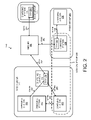
- FIG. 7 is a block diagram illustrating an exemplary architecture of a computing device that may be used in some embodiments of the invention.
- references in the specification to “one embodiment”, “an embodiment”, “an example embodiment”, etc., indicate that the embodiment described may include a particular feature, structure, or characteristic, but every embodiment may not necessarily include the particular feature, structure, or characteristic. Moreover, such phrases are not necessarily referring to the same embodiment. Further, when a particular feature, structure, or characteristic is described in connection with an embodiment, it is submitted that it is within the knowledge of one skilled in the art to effect such feature, structure, or characteristic in connection with other embodiments whether or not explicitly described.
- Coupled may mean that two or more elements are in direct physical or electrical contact. However, “coupled” may also mean that two or more elements are not in direct contact with each other, but yet still co-operate or interact with each other.
- a charging station is a piece of equipment, including hardware and software, to charge electric vehicles.
- Such computing devices store and communicate (internally and with other computing devices over a network) code and data using machine-readable media, such as machine storage media (e.g., magnetic disks; optical disks; random access memory; read only memory; flash memory devices; phase-change memory) and machine communication media (e.g., electrical, optical, acoustical or other form of propagated signals—such as carrier waves, infrared signals, digital signals, etc.).
- machine storage media e.g., magnetic disks; optical disks; random access memory; read only memory; flash memory devices; phase-change memory
- machine communication media e.g., electrical, optical, acoustical or other form of propagated signals—such as carrier waves, infrared signals, digital signals, etc.
- such computing devices typically include a set of one or more processors coupled to one or more other components, such as a storage device, one or more input/output devices (e.g., a keyboard, a touchscreen, and/or a display), and a network connection.
- the coupling of the set of processors and other components is typically through one or more busses and bridges (also termed as bus controllers).
- the storage device and signals carrying the network traffic respectively represent one or more machine storage media and machine communication media.
- the storage device of a given device typically stores code and/or data for execution on the set of one or more processors of that device.
- one or more parts of an embodiment of the invention may be implemented using different combinations of software, firmware, and/or hardware.
- FIG. 1 illustrates an exemplary charging system according to one embodiment of the invention.
- the charging system illustrated in FIG. 1 includes the electric vehicle charging station 120 (hereinafter referred to as the “charging station 120 ”), which is coupled with the power grid 130 over the power line 135 .
- the power grid 130 may be owned and/or operated by local utility companies or owned and/or operated by private persons/companies.
- the charging station 120 is also coupled with the data control unit 170 over the WPAN (Wireless Personal Area Network) line 175 (e.g., Bluetooth, ZigBee, etc.) or other LAN (Local Area Network) links (e.g., Ethernet, PLC, WiFi, etc.).
- WPAN Wireless Personal Area Network
- LAN Local Area Network
- the data control unit 170 is coupled with the electric vehicle charging station network server 180 (hereinafter “server” 180 ) over the WAN (Wide Access Network) connection 185 (e.g., Cellular (e.g., CDMA, GPRS, etc.) WiFi Internet connection, Plain Old Telephone Service, leased line, etc.).
- server 180 the electric vehicle charging station network server 180
- WAN Wide Access Network
- WiFi Internet connection e.g., Cellular (e.g., CDMA, GPRS, etc.) WiFi Internet connection, Plain Old Telephone Service, leased line, etc.
- the data control unit 170 relays messages between the charging station 120 and the server 180 .
- the data control unit 170 is part of another charging station as will be described in more detail with reference to FIG. 2 .
- the charging station 120 controls the application of electricity from the power grid 130 to the power receptacle 115 .
- the power receptacle 115 may be any number of types of receptacles such as receptacles conforming to the NEMA (National Electrical Manufacturers Association) standards 5-15, 5-20, and 14-50 or other standards (e.g., BS 1363, CEE7, etc.) and may be operating at different voltages (e.g., 120V, 240V, 230V, etc.).
- NEMA National Electrical Manufacturers Association
- a lockable door covers the power receptacle 115 and is locked in a closed position (without a cord being plugged in while the charging station 120 is not in use) and locked in a charging position (while a cord is plugged into the power receptacle during a charging session). While the door is locked in the charging position, the charging cord plugged into the power receptacle 115 cannot be removed. Only authorized vehicle operators (those authorized to use the charging station 120 ) and authorized administrative personnel can unlock the door to access the power receptacle 115 . Thus, access to the power receptacle 115 is limited to authorized vehicle operators and administrative personnel (e.g., utility workers, operators of the charging system network, etc.). Thus, the locking door protects the power receptacle 115 while the charging station 120 is not in use and also prevents charging cords from being unplugged by unauthorized persons during charging.
- Operators of vehicles may use the charging station 120 to charge their electric vehicles.
- the electricity storage devices e.g., batteries, supercapacitors, etc.
- electric vehicles e.g., electric powered vehicles, gasoline/electric powered vehicle hybrids, etc.
- the operators of electric vehicles provide their own charging cord to charge their electric vehicle.
- the electric vehicle operator 145 plugs the electrical connector 160 of the charging cord 140 into on-board charging circuitry of the electric vehicle 110 (which is coupled with the electricity storage device of the vehicle 110 ) and plugs the electrical connector 165 of the charging cord 140 into the power receptacle 115 .
- the electric vehicle operator 145 may use the communication device 150 to initiate and request a charging session for the electric vehicle 110 .
- the communication device 150 may be a WLAN or WPAN device (e.g., one or two-way radio-frequency identification (RFID) device, mobile computing device (e.g., laptops, palmtop, smartphone, multimedia mobile phone, cellular phone, etc.)), ZigBee device, etc.
- RFID radio-frequency identification
- the communication device 150 communicates unique operator-specific information (e.g., operator identification information, etc.) to the charging station 120 (either directly or indirectly through the server 180 ).
- electric vehicle operator 145 may use the communication device 150 to monitor the charging status of the electric vehicle 110 .
- the communication device 150 may be coupled with the electric vehicle 110 .
- the charging station 120 locally determines whether the operator 145 is authorized (e.g., by checking whether the operator 145 is represented on a list of authorized users stored in the charging station 120 ).
- the charging station 120 may transmit an authorization request that includes the information read from the communication device 150 to the server 180 (through the data control unit 170 ) for authorization.
- the server 180 receives the charging session request from the operator 145 directly and determines whether the operator 145 is authorized.
- the charging station 120 if the operator 145 is authorized, the charging station 120 energizes the power receptacle 115 . Additionally, if there is a locked door covering the power receptacle 115 , the charging station 120 unlocks that door to allow the operator 145 to plug in the charging cord 140 .
- the operator 145 may request a charging session from the charging station 120 differently in some embodiments of the invention.
- the operator 145 may interact with a payment station coupled with the charging station 120 , which may then send appropriate instructions to the charging station 120 regarding the charging of the vehicle 110 (e.g., instructions to unlock the door covering the power receptacle 115 , energize the power receptacle 115 , etc.).
- the payment station may function similarly to a payment station for a parking space.
- the payment station coupled with the charging station may be used both for parking payment and charging payment.
- a charging session is established after an operator has been authenticated and authorized to initiate a charging session (e.g., may use the charging station 120 at the particular time of the day), after a charging cord has been plugged into the power receptacle 115 , and after the door to the power receptacle 115 has been closed and locked.
- a charging session is established with the vehicle 110 after the operator 145 has been authorized, after the charging cord 140 has been plugged into the power receptacle 115 , and after the door covering the power receptacle 115 has been closed and locked.
- the server 180 provides services for multiple charging stations.
- the server 180 stores vehicle operator information (e.g., operator account information, operator contact information (e.g., operator name, street address, email address, telephone number, etc.)) and typically is responsible for accounting (e.g., amount of electricity purchased by individual vehicle operators, etc.).
- the server 180 includes a subscriber portal (available through the Internet) which allows subscribers (owners and operators of electric vehicles) to register for service (which may include providing information regarding their electric vehicles, providing payment information, providing contact information, etc.) and perform other functions (e.g., pay for charging sessions, determine availability of charging stations, check the charging status of their electric vehicle(s), etc.).
- the server 180 may include a host portal (available through the Internet) which allows owners or administrators of the charging station to configure their charging stations and perform other functions (e.g., determine average usage of charging stations, etc.). Charging stations may also be configured using other means (e.g., through Telnet, user interface, etc.) in some embodiments of the invention.
- host portal available through the Internet
- Charging stations may also be configured using other means (e.g., through Telnet, user interface, etc.) in some embodiments of the invention.
- FIG. 1 illustrates a single charging station 120
- many charging stations may be networked to the server 180 (through one or more data control units) and/or to each other.
- FIG. 2 illustrates an exemplary network of charging stations according to one embodiment of the invention.
- the charging station network 200 includes the server 180 and the charging stations 120 , 210 , 215 , 220 , 225 , 230 , and 235 .
- the server 180 is providing services for each of the charging stations 120 , 210 , 215 , 220 , 225 , 230 , and 235 .
- the charging stations 120 , 210 , 215 , and 220 are part of the radio group 270 .
- the charging stations 230 and 235 are part of the radio group 280 .
- the charging station 225 is the only charging station in the radio group 275 .
- a radio group is a collection of one or more charging stations that collectively has a single connection to a server.
- Each radio group includes one or more data control units (DCUs) which connect the charging stations with the server.
- DCUs are implemented along with a charging station.
- a data control unit may be implemented separately from any charging station.
- Each DCU acts as a gateway to the server 180 for those charging stations that are coupled with that DCU.
- charging stations need not have a direct link to a DCU (e.g., a charging station may be directly linked to another charging station which itself has a direct link to a DCU).
- DCU 170 (of the radio group 270 and implemented in the charging station 220 ) is coupled with the server 180 through the WAN link 292 and is coupled with each of the charging stations 120 , 210 , and 215 .
- the charging stations 120 and 215 are directly coupled with the DCU 170 via the WPAN links 282 and 286 respectively.
- the charging station 210 is indirectly coupled with the DCU 170 via the WPAN link 284 to the charging station 215 which is itself directly coupled with the DCU 170 via the WPAN link 286 .
- the charging stations 120 , 210 , and 215 transmit messages to, and receive messages from, the server 180 via the DCU 170 .
- the DCU 225 (of the radio group 275 and part of the charging station 225 ) is coupled with the server 180 through the WAN link 296 .
- the DCU 260 (of the radio group 280 ) is coupled with the server 180 through the WAN link 294 and is coupled with the charging station 230 via the WPAN link 288 .
- Radio groups represent the network topology of a collection of charging stations. Typically, these charging stations are located relatively close (e.g., on the same street, in the same parking garage, in the same block, etc.).
- administrator defined collection of charging stations may also be defined.
- the charging stations 215 and 235 are part of the logical group 285 .
- Logical groups are a collection of one or more charging stations that an administrator defines. Typically, the charging stations included in a logical group share some set of common features. As illustrated in FIG. 2 , logical groups may include charging stations from different radio groups.
- each charging station may have a direct connection with the server 180 ).
- FIG. 3 illustrates an exemplary embodiment of the charging station 120 according to one embodiment of the invention.
- the charging station 120 includes the charging station controller 305 , the electricity control device 310 , the electricity measuring device 320 , the RFID reader 330 , the user interface 335 , the display unit 340 , and one or more transceivers 350 (e.g., wired transceiver(s) (e.g., Ethernet, power line communication (PLC), etc.) and/or wireless transceiver(s) (e.g., 802.15.4 (e.g., ZigBee, etc.), Bluetooth, WiFi, Infrared, GPRS/GSM, CDMA, etc.)).
- PLC power line communication
- FIG. 3 illustrates an exemplary architecture of a charging station, and other, different architectures may be used in embodiments of the invention described herein.
- some implementations of charging stations may not include a user interface, an RFID reader, or a connection to a network.
- the RFID reader 330 reads RFID tags from RFID enabled devices (e.g., smartcards, key fobs, etc., embedded with RFID tag(s)) of operators that want to use the charging station 120 .
- the operator 145 may wave/swipe the communication device 150 (if an RFID enabled device) near the RFID reader 330 to initiate a charging session from the charging station 120 .
- the RFID reader 330 passes the information read to the charging station controller 305 .
- the charging station controller 305 is programmed to include instructions that establish charging sessions with the vehicles.
- a charging session is established after an operator has been authenticated and authorized to initiate a charging session (e.g., may use the charging station 120 at the particular time of the day), after a charging cord has been plugged into the power receptacle 115 , and after the door covering the power receptacle 115 has been closed and locked.
- the operator 145 is authenticated and authorized based on the information the RFID reader 330 receives.
- the charging station 120 While in one embodiment of the invention the charging station 120 locally stores authentication information (e.g., in the configuration/operator data store 370 ), in other embodiments of the invention the charging station controller 305 transmits an authorization request with a remote device (e.g., the server 180 ) via one of the transceivers 350 .
- the charging station controller causes an authorization request to be transmitted to the data control unit 170 over a WPAN transceiver (e.g., Bluetooth, ZigBee) or a LAN transceiver.
- the data control unit 170 relays the authorization request to the server 180 .
- vehicle operators may use the user interface 335 to initiate charging sessions. For example, vehicle operators may enter in account and/or payment information through the user interface 335 .
- the user interface 335 may allow the operator 145 to enter in their username/password (or other information) and/or payment information.
- vehicle operators may request charging sessions through devices remote to the charging station 120 (e.g., payment stations coupled with the charging stations).
- the charging station controller 305 After authorizing the operator 145 , the charging station controller 305 causes the power receptacle 115 to be energized and the door covering the power receptacle 115 (if a locked door is covering the power receptacle 115 ) to unlock. For example, the charging station controller 305 causes the electricity control device 310 to complete the connection of the power line 135 to the power grid 130 .
- the electricity control device 310 is a solid-state device that is controlled by the charging station controller 305 or any other device suitable for controlling the flow of electricity.
- the charging station controller 305 causes the door covering the power receptacle 115 to unlock allowing the operator 145 to plug in their charging cord to the power receptacle 115 .
- the charging station 120 includes one or more sensors that may be used to detect when a charging cord has been plugged into the power receptacle 115 .
- the sensors may be a pair of infrared emitting diodes (IRED) and a phototransistor or a photodiode.
- IRED infrared emitting diodes
- An IRED emits light and a phototransistor or photodiode detects the light and converts the light into current.
- the power receptacle 115 receives a plug, that plug breaks the light causing the phototransistor to stop converting light into current. In this way, the charging station 120 may determine if a plug has been inserted into the power receptacle 115 .
- the charging station 120 also includes sensors to detect whether the door covering the power receptacle 115 is closed and locked.
- the electricity measuring device 320 measures the amount of electricity that is flowing on the power line 135 through the power receptacle 115 . While in one embodiment of the invention the electricity measuring device 320 measures flow of current, in an alternative embodiment of the invention the electricity measuring device 320 measures power draw.
- the electricity measuring device 320 may be an induction coil or other devices suitable for measuring electricity.
- the charging station controller 305 is programmed with instructions to monitor the electricity measuring device 320 and to calculate the amount of electricity being used over a given time period.
- the display unit 340 is used to display messages to the operator 145 (e.g., charging status, confirmation messages, error messages, notification messages, etc.).
- the display unit 340 may also display parking information if the charging station 120 is also acting as a parking meter (e.g., amount of time remaining in minutes, parking violation, etc.).
- the configuration/operator data store 370 stores configuration information which may be set by administrators, owners, or manufacturers of the charging station 120 .
- FIG. 4 illustrates exemplary portals of the server 180 according to one embodiment of the invention.
- the subscriber portal 410 includes the subscriber registration module 415 , the charging station locator module 420 , the charge status module 425 , and the subscriber accounting module 430 .
- the subscriber registration module 415 allows potential customers (e.g., electric vehicle operators) to sign up for charging services.
- the subscriber registration module 415 collects contact point information from subscribers (e.g., name, address, email address, telephone number, etc.), type of electric vehicle(s) and/or type of electricity storage device, and service plan information.
- the subscribers may select between different types and levels of services in different embodiments of the invention.
- the subscribers may choose between different subscription plans (e.g., pay per charging session, nighttime charging, grid-friendly charging (subscribers can only charge during off-peak times (e.g., early morning, late night, or other times when the grid is experiencing low demand), anytime charging (access to the charging stations twenty-four hours a day), etc.).
- subscription plans e.g., pay per charging session, nighttime charging, grid-friendly charging (subscribers can only charge during off-peak times (e.g., early morning, late night, or other times when the grid is experiencing low demand), anytime charging (access to the charging stations twenty-four hours a day), etc.).
- the subscriber registration module 415 also allows subscribers to provide notification message preferences for receiving notification messages upon certain events occurring. For example, each subscriber may provide a notification message preference to receive notification messages for each event that interests them (those events the subscriber wishes to receive notification messages on).
- the events of interest may include one or more suspension or termination of a charging session events, one or more charge status events, one or more update events, one or more parking events, and/or one or more alarm events.
- each subscriber may provide a notification message preference for an event in interest (whether they want to receive a notification message for that event) for the following events: fully charged vehicle, charging has been interrupted (e.g., the charging cord has been removed from the vehicle or has been severed, the station has encountered a power loss, etc.), the utility operating the power grid has caused their charging of the vehicle to be suspended (e.g., the load on the grid exceeded a Demand Response threshold), the subscriber forgot to plug in their charging cord into their vehicle, and other events which will be described in greater detail later herein.
- the subscribers may choose to receive one or any combination of the above events that interest them.
- the subscribers may be able to choose the format of the notification messages (e.g., receive through email, through text message, etc.).
- the subscribers may provide one or more contact points specific for notification messages (e.g., email address(es), text message address(es) (e.g., phone number(s)), etc.). It should also be understood that one or more events may have default notification message preference values.
- the charging station locator module 420 allows subscribers to locate charging stations (available and/or unavailable charging stations).
- the charging station locator module 420 may provide an interactive map for the subscribers to locate charging stations.
- the charging station locator module 420 may also provide an estimated time when the charging station will become available for use.
- Subscribers may also use the charging station locator module 420 to create a list of favorite charging station(s) for the server 180 to monitor their availability and notify the user (e.g., through email or text message) when those charging station(s) are available and/or unavailable.
- the subscribers may use the charging station locator module 420 to reserve charging stations for future use.
- the charge status module 425 allows subscribers to determine the charging status of their electric vehicles (that are currently being charged). According to one embodiment of the invention, the charge status module 425 presents charge status information to the subscriber (e.g., amount of power currently being transferred, total amount of power transferred, amount of energy transferred, total amount of energy transferred, the amount of time the charging session has lasted, an estimate of the time left to charge their vehicle, etc.).
- charge status information e.g., amount of power currently being transferred, total amount of power transferred, amount of energy transferred, total amount of energy transferred, the amount of time the charging session has lasted, an estimate of the time left to charge their vehicle, etc.
- the subscriber accounting module 430 allows subscribers to review accounting information (e.g., the number of sessions remaining in their subscription, payment and/or invoice information, the amount of energy transferred to the power grid, etc.), and/or generate report(s) (e.g., illustrating power consumed from the power grid, illustrating power transferred to the power grid, illustrating an estimate of the amount of gasoline saved through use of their electric vehicle(s), illustrating an estimate of the amount of greenhouse gases they have saved from outputting through use of their electric vehicle(s), illustrating the amount of money saved in gasoline costs through use of their electric vehicle(s), etc.).
- the subscriber accounting module 430 may allow subscribers to review a history of the charging station(s) that they most often use.
- the host portal 435 allows owners and/or administrators of one or more charging stations to configure their charging station(s) and perform other functions.
- a host is an owner and/or administrator of one or more charging stations. It should also be understood that a host may include operator(s) and/or administrator(s) of the charging station network (e.g., the charging station network 200 ).
- the host portal 435 includes the host registration module 440 , the charging station configurator module 445 , the host accounting module 450 , and the charging station status module 455 .
- the host registration module 440 allows hosts to register their charging station(s) for service and allows hosts to set preferences. For example, the host registration module 440 allows hosts to provide contact information (e.g., name, company, address, email address(es), telephone number(s), etc.). As another example, the host preferences module 440 allows hosts to provide notification message preferences for receiving notification messages upon certain events occurring. For example, each host may provide a notification message preference to receive notification messages for each event that interests them (those events the host wishes to receive notification messages on). The events of interest may include one or more suspension or termination of a charging session events, one or more update events, and/or one or more alarm events.
- contact information e.g., name, company, address, email address(es), telephone number(s), etc.
- the host preferences module 440 allows hosts to provide notification message preferences for receiving notification messages upon certain events occurring. For example, each host may provide a notification message preference to receive notification messages for each event that interests them (those events the host wishes to receive notification messages on).
- each host may provide a notification message preference for any of the following events that interest them: a charging station has failed to respond to a periodic heartbeat from the server 180 , a charging station has unexpectedly rebooted, a charging station has detected a problem, a ground fault circuit interrupter (GFCI) has tripped in a charging station, etc. and/or other events which will be described in greater detail later herein.
- GFCI ground fault circuit interrupter
- Each host may choose to receive one or any combination of the above events that interest them, and may specify different notification message preferences for different charging stations.
- each host may be able to choose the format of the notification messages (e.g., receive them through email, through text message, etc.).
- the hosts may provide one or more contact points specific for notification messages (e.g., email address(es), text message address(es) (e.g., phone number(s)), etc.). It should also be understood that one or more events may have default notification message preference values.
- the charging station configurator module 445 allows hosts to configure their charging stations (e.g., set charging station parameters on their charging station, set access parameters, etc.).
- the host accounting module 450 allows hosts to review accounting information (e.g., power consumed by each of their charging station(s), total power consumed by all of their charging station(s), power transferred to the power grid by each of their charging station(s), total power transferred to the power grid by all of their charging station(s), account balances, payments and invoices, etc.).
- the charging station status module 455 allows hosts to view the charging status of each of their charging station(s) (e.g., current status (charging, available, out-of-service), reports on occupancy rates of their charging station(s), reports on energy usage for each of their charging station(s), etc.).
- current status charging, available, out-of-service
- occupancy rates of their charging station(s) reports on energy usage for each of their charging station(s), etc.
- the utility portal 460 allows utilities (employees of the utilities) to monitor and manage the impact on their grid of electric vehicle charging.
- the load monitoring module 465 allows utilities to monitor the load for individual charging stations and/or aggregate load of all charging stations drawing power from their grid.
- the load monitoring module 465 may also provide the amount of load which may be shed-able (e.g., the amount of load being drawn by subscribers which have registered for grid-friendly charging, etc.).
- the utilities may use the information from the load monitoring module 465 to determine whether to shed load (e.g., for only those subscribers which have registered for grid-friendly charging or for all charging sessions).
- the server 180 may send a command to shut down service to those charging stations.
- the load monitoring module 465 may provide a history of use for the charging stations including the average load drawn at a time for each charging station and/or all charging stations.
- While the subscriber portal 410 , the host portal 435 , and the utility portal 460 have been described with specific modules, it should be understood that they may have additional modules, less modules, and/or the functionality of some modules may be combined.
- the server 180 is also programmed to transmit notification messages to subscribers and hosts based on data received from the charging stations (e.g., charging data, alarm data, etc.), data received from the utilities (e.g., Demand Response data, etc.), data gathered by the server 180 (e.g., network condition data, etc.), and in some embodiments of the invention, data received from the electric vehicles.
- these notification messages take the form of electronic messages (e.g., email messages, text messages, or other forms of electronic communication).
- the server 180 may be programmed to transmit notification messages to subscribers, hosts, or other persons, in different situations in different embodiments of the invention.
- the server 180 is programmed to transmit notification messages to subscribers (or to other person(s) as designated by the subscribers) and/or hosts upon events that cause charging sessions to be terminated or suspended in the following situations: responsive to their charging session being administratively terminated by the owner(s) and/or administrator(s) of the charging station, responsive to the charging station detecting an over-current situation and suspending the charging session, responsive to the charging station stopping the flow of electricity to their vehicle (e.g., by de-energizing the power receptacle), responsive to their charging session expiring and being suspended, responsive to receiving a Demand Response message from a Utility to suspend charging to decrease load on the power grid, etc.
- the server 180 is programmed to transmit notification messages to subscribers (or to other person(s) as designated by the subscribers), and/or hosts upon the following charge status events: fully charged vehicle, X percent charge, vehicle is not currently charging (e.g., operator established a charging session but has failed to plug their charging cord into their vehicle or the connection is otherwise faulty), vehicle has resumed charging (e.g., after being suspended to decrease the load on the power grid), a vehicle is currently transferring electricity to the grid, a vehicle is currently drawing electricity from the grid, etc.
- the determination that the electricity storage device(s) of an electric vehicle is fully charged may be performed in different ways in different embodiments of the invention.
- the storage capability of a particular electricity storage device for a given electric vehicle is known based on the type of electric vehicle information collected by the subscriber registration module 415 . From that information, the maximum amount of time needed to charge that electricity storage device may be determined.
- the electricity storage device of a given electric vehicle is fully charged when at least the total amount of electricity transferred to the electricity storage device meets or exceeds the storage capability amount of that electricity storage device.
- the electricity storage device of a given electric vehicle is fully charged at least when the maximum amount of time needed to charge that electricity storage device has been meet or exceeded.
- the “trickle charge” amount of electricity is known for an electricity storage device, that electricity storage device is fully charged when that trickle charge amount is detected.
- the determination is typically based on data received from the charging stations.
- the determination of a fully charged vehicle is made based on information collected from the electric vehicles.
- some electric vehicles have the capability of transmitting status information (e.g., via PLC, WPAN, etc.) of their electricity storage devices (e.g., percent full, amount of energy needed until a full charge, full charge, etc.).
- This data may be transmitted directly or indirectly to the server 180 and/or the charging station 120 .
- the server 180 and/or the charging station 120 may use the data to transmit charge status notification messages.
- the server 180 and/or the charging station 120 may use this information in combination with the amount of electricity being transferred to the electricity storage device to determine a fully charged electricity storage device.
- the server 180 and/or charging station 120 may transmit fully charged vehicle notification messages responsive to receiving a fully charged message from the electric vehicle.
- the server 180 is programmed to determine that a subscriber has established a charging session with a charging station but has failed to plug their charging cord into their vehicle by examining the charging data received from that charging station. For example, if the charging data indicates that the charging session has been established for a threshold amount of seconds and the electricity transferred is below a certain threshold, the server 180 may notify the subscriber that charging has not occurred. In addition, the server 180 may transmit a command to the charging station instructing it to suspend the session and prevent electricity from flowing through the power receptacle.
- the server 180 is programmed to transmit notification messages to those subscribers (or to other person(s) as designated by the subscribers) which have established a charging session but have failed to plug their charging cord into their vehicle (or otherwise have a bad connection to their vehicle). For example, a vehicle operator has been authorized to use a charging station, a charging cord has been inserted into a power receptacle of the charging station, the door covering the power receptacle (if one exists) is closed and locked, but the vehicle operator has forgotten to plug the charging cord into their vehicle.
- the server 180 determines that a subscriber has established a charging session with a charging station but has failed to plug their charging cord into their vehicle by examining the charging data received from that charging station. For example, if the charging data indicates that the charging session has been established for a threshold amount of seconds and the electricity transferred is below a certain threshold, the server 180 may notify the subscriber that charging has not occurred. In addition, the server 180 may transmit a command to the charging station instructing it to suspend the session and prevent electricity from flowing through the power receptacle.
- the server 180 is programmed to transmit notification messages responsive to an alarm generated by a charging station or triggered by the server 180 . These notification messages may be sent to the appropriate operators, administrators, and/or owners of the charging stations experiencing an alarm event and/or to the subscribers using a charging station that is experiencing an alarm event.
- Example alarm events include the following: a charging station has failed to respond to a periodic heartbeat from the server 180 , a charging station has unexpectedly rebooted, a charging station has detected a problem (hardware and/or software), a GFCI in the charging station has tripped, a software and/or firmware update/upgrade on a charging station has completed and/or failed, the software and/or firmware on a charging station has reverted to an old version, etc.
- the server 180 is programmed to transmit update notification messages to the subscribers responsive to certain update events.
- Example update events include the following: a favorite charging station or often used charging station is available and/or unavailable, a new charging station has been installed in a close location, a subscriber has run out of (or is close to running out of) charging sessions, a subscriber has failed or completed a credit card authorization check (e.g., credit card has expired), the door covering the power receptacle where their charging cord is attached has been opened by an unauthorized user, etc.
- the server 180 is programmed to transmit notification messages to subscribers responsive to parking events including the following: exceeded parking time (or close to exceeding the parking time), parking reservation confirmation, unused parking reservation (e.g., a subscriber has reserved a parking spot but did not use the spot and/or did not charge at a corresponding charging station), parking reservation time extension confirmation, etc.
- the charging stations may include logic to determine whether to transmit notification messages to subscribers and/or hosts.
- the charging station controller 305 may be programmed to determine whether to transmit notification messages to subscribers using the charging station or to the host associated with the charging station.
- the charging station 120 may include the notification message preferences of the operator 145 and the administrator(s) and/or owner(s) of the charging station 120 .
- the charging stations may transmit the notification messages to subscribers and/or hosts.
- FIG. 5 is a flow diagram illustrating exemplary operations for transmitting notification messages to subscribers according to one embodiment of the invention.
- the operations of FIG. 5 will be described with reference to the exemplary embodiments of FIGS. 1 and 4 . However, it should be understood that the operations of FIG. 5 can be performed by embodiments of the invention other than those discussed with reference to FIGS. 1 and 4 , and the embodiments discussed with reference to FIGS. 1 and 4 can perform operations different than those discussed with reference to FIG. 5 .
- the operations of FIG. 5 are performed by servers (e.g., the server 180 ).
- the server 180 receives notification message preferences for a subscriber (e.g., the operator 145 ) which indicate one or more events of interest which the subscriber wishes to receive notification messages on. While in one embodiment of the invention the server 180 receives these notification message preferences from the subscriber using the subscriber registration module 415 , in other embodiments of the invention the server 180 receives these notification message preferences differently (e.g., via email, via text message, from a charging station, etc.). Flow moves from block 510 to block 520 .
- the server 180 receives a set of one or more contact points (e.g., email address(es), text message address(es), etc.) associated with the subscriber. While in one embodiment of the invention the server 180 receives the set of contact points from the subscriber using the subscriber registration module 415 , in other embodiments of the invention the server 180 receives the set of contact points differently (e.g., via email, via text message, from a charging station, etc.). Flow moves from block 520 to block 530 .
- contact points e.g., email address(es), text message address(es), etc.
- the server 180 authorizes the subscriber to use a charging station. For example, the server 180 authorizes the operator 145 to use the charging station 120 . In some embodiments, the authorization is performed in response to the server 180 receiving an authorization request from the charging station 120 , while in other embodiments, the authorization is performed in response to the server 180 receiving an authorization request from the subscriber (e.g., the operator 145 ) directly. Flow moves from block 530 to block 540 .
- the server 180 receives data associated with the subscriber that indicates a charging session has been established for an electric vehicle (e.g., electric vehicle 110 ) associated with the subscriber.
- the data received may be transmitted by the charging station 120 .
- the data includes information identifying the subscriber (e.g., an RFID tag uniquely associated with the subscriber) and information indicating that a charging session has been established. Flow moves from block 540 to block 550 .
- the server 180 detects an event of interest for the subscriber.
- the server 180 may detect an event of interest for the subscriber (e.g., operator 145 ) based on data received from the charging stations (e.g., data related to the charging of the vehicle 110 , data related to alarms detected and/or generated at the charging station, etc.), data received from the utility operating the power grid 130 (e.g., Demand Response data, etc.), data gathered by the server 180 (e.g., network condition data, etc.), data provided by the administrator(s) and/or owner(s) of the charging station 120 , (e.g., network operation data), and in some embodiments of the invention, data received from the electric vehicle 110 (e.g., data related to the charging of the electric vehicle 110 ).
- Flow moves from block 550 to block 560 .
- the server 180 Responsive to detecting an event of interest for the subscriber, at block 560 the server 180 transmits a notification message for that event to at least one of the contact points associated with the subscriber.
- the notification message sent is an email, text message, or other electronic communication to one or more addresses as specified by the subscriber (which may be provided using the subscriber registration module 415 ).
- the subscriber may specify the format of the notification message (e.g., email, text message, etc.) and the recipient of the message using the subscriber registration module 415 .
- FIG. 6 is a flow diagram illustrating exemplary operations for transmitting notification messages to hosts according to one embodiment of the invention.
- the operations of FIG. 6 will be described with reference to the exemplary embodiments of FIGS. 1 and 4 .
- the operations of FIG. 6 can be performed by embodiments of the invention other than those discussed with reference to FIGS. 1 and 4 , and the embodiments discussed with reference to FIGS. 1 and 4 can perform operations different than those discussed with reference to FIG. 6 .
- the operations described with reference to FIG. 6 may be performed in combination to, or separate from, the operations described with reference to FIG. 5 .
- the server 180 receives notification message preferences for a host (e.g., an owner or administrator of the charging station 120 and/or operator(s) and/or administrator(s) of the charging station network 200 ) which indicates one or more events of interest which the host wishes to receive notification messages for. While in one embodiment of the invention the server 180 receives these notification message preferences from the host using the host registration module 440 , in other embodiments of the invention the server 180 receives these preferences differently (e.g., via email, via text message, etc.). Flow moves from block 610 to block 620 .
- a host e.g., an owner or administrator of the charging station 120 and/or operator(s) and/or administrator(s) of the charging station network 200
- the server 180 receives these notification message preferences from the host using the host registration module 440
- the server 180 receives these preferences differently (e.g., via email, via text message, etc.).
- Flow moves from block 610 to block 620 .
- the server 180 receives a set of one or more contact points (e.g., email address(es), text message address(es), etc.) associated with the host. While in one embodiment of the invention the server 180 receives the set of contact points from the host using the host registration module 440 , in other embodiments of the invention the server 180 receives the set of contact points differently (e.g., via email, via text message, etc.). Flow moves from block 620 to block 630 .
- contact points e.g., email address(es), text message address(es), etc.
- the server 180 detects an event of interest for the host.
- the server 180 may detect an event of interest for the host based on data received from those charging station(s) the host owns or operates (e.g., data related to vehicle charging at their charging station(s), data related to alarms detected and/or generated at their charging station(s), etc.), data received from the utility(ies) operating the power grid(s) for their charging station(s) (e.g., Demand Response data, etc.), data gathered by the server 180 for their charging station(s) (e.g., network condition data, hardware/software upgrade status of the charging stations, etc.), and in some embodiments of the invention, data received from the electric vehicles (e.g., data related to the charging of the electric vehicles at their charging station(s)).
- Flow moves from block 630 to 640 .
- the server 180 Responsive to detecting an event of interest for the host, at block 640 the server 180 transmits a notification message for that event to at least one of the contact points associated with the host.
- the notification message sent is an email, text message, or other electronic communication to one or more addresses as specified by the host (which may be provided using the host registration module 440 ).
- the host may specify the format of the notification message (e.g., email, text message, etc.) and the recipient of the message using the host registration module 440 .
- FIG. 7 is a block diagram illustrating an exemplary architecture of a computing device which may be used in embodiments of the invention.
- the architecture of the computing device 700 may be an architecture of the server 180 and or the charging station 120 in some embodiments of the invention.
- FIG. 7 illustrates various components of a computing device, it is not intended to represent any particular architecture or manner of interconnecting the components as such details are not germane to the present invention. It will be appreciated that other computing devices that have fewer components or more components may also be used with the present invention.
- the computing device 700 includes the bus(es) 750 which is coupled with the processing system 720 , power supply 725 , memory 730 , and the nonvolatile memory 740 (e.g., a hard drive, flash memory, Phase-Change Memory (PCM), etc.).
- the bus(es) 750 may be connected to each other through various bridges, controllers, and/or adapters as is well known in the art.
- the processing system 720 may retrieve instruction(s) from the memory 730 and/or the nonvolatile memory 740 , and execute the instructions to perform operations as described above.
- the bus 750 interconnects the above components together and also interconnects those components to the display controller & display device 770 , Input/Output device(s) 780 (e.g., NIC (Network Interface Card), a cursor control (e.g., mouse, touchscreen, touchpad, etc.), a keyboard, etc.), and the transceiver(s) 1290 (wired transceiver(s) (e.g., Ethernet, power line communication (PLC), etc.) and/or wireless transceiver(s) (e.g., 802.15.4 (e.g., ZigBee, etc.), Bluetooth, WiFi, Infrared, GPRS/GSM, CDMA, RFID, etc.)).
- NIC Network Interface Card
- PLC power line communication
- wireless transceiver(s) 1290 wireless transceiver(s) and/or wireless transceiver(s) (e.g., 802.15.4 (e.g., ZigBee, etc.), Bluetooth, WiFi, In
- the charging cord may be attached differently to the charging station (e.g., the charging cord is permanently attached to the power receptacle and each of the electric vehicle operators use the same charging cord, the charging cord is permanently attached to the electricity source of the charging station, etc.).
Landscapes
- Engineering & Computer Science (AREA)
- Power Engineering (AREA)
- Transportation (AREA)
- Mechanical Engineering (AREA)
- Life Sciences & Earth Sciences (AREA)
- Sustainable Development (AREA)
- Sustainable Energy (AREA)
- Health & Medical Sciences (AREA)
- Computing Systems (AREA)
- General Health & Medical Sciences (AREA)
- Medical Informatics (AREA)
- Computer Networks & Wireless Communication (AREA)
- Signal Processing (AREA)
- Charge And Discharge Circuits For Batteries Or The Like (AREA)
- Electric Propulsion And Braking For Vehicles (AREA)
- Secondary Cells (AREA)
Abstract
Description
Claims (42)
Priority Applications (9)
| Application Number | Priority Date | Filing Date | Title |
|---|---|---|---|
| US12/372,726 US10189359B2 (en) | 2009-02-17 | 2009-02-17 | Transmitting notification messages for an electric vehicle charging network |
| EP10744268.3A EP2399216A4 (en) | 2009-02-17 | 2010-02-17 | Transmitting notification messages for an electric vehicle charging network |
| PCT/US2010/024496 WO2010096502A1 (en) | 2009-02-17 | 2010-02-17 | Transmitting notification messages for an electric vehicle charging network |
| AU2010216049A AU2010216049A1 (en) | 2009-02-17 | 2010-02-17 | Transmitting notification messages for an electric vehicle charging network |
| JP2011551195A JP5432292B2 (en) | 2009-02-17 | 2010-02-17 | Transmission of notification messages for electric vehicle charging networks |
| AU2016208355A AU2016208355A1 (en) | 2009-02-17 | 2016-07-28 | Transmitting notification messages for an electric vehicle charging network |
| AU2018203068A AU2018203068A1 (en) | 2009-02-17 | 2018-05-02 | Transmitting notification messages for an electric vehicle charging network |
| US16/259,871 US11407320B2 (en) | 2009-02-17 | 2019-01-28 | Transmitting notification messages for an electric vehicle charging network |
| US17/818,259 US20220371465A1 (en) | 2009-02-17 | 2022-08-08 | Transmitting Notification Messages for an Electric Vehicle Charging Network |
Applications Claiming Priority (1)
| Application Number | Priority Date | Filing Date | Title |
|---|---|---|---|
| US12/372,726 US10189359B2 (en) | 2009-02-17 | 2009-02-17 | Transmitting notification messages for an electric vehicle charging network |
Related Child Applications (1)
| Application Number | Title | Priority Date | Filing Date |
|---|---|---|---|
| US16/259,871 Continuation US11407320B2 (en) | 2009-02-17 | 2019-01-28 | Transmitting notification messages for an electric vehicle charging network |
Publications (2)
| Publication Number | Publication Date |
|---|---|
| US20100211643A1 US20100211643A1 (en) | 2010-08-19 |
| US10189359B2 true US10189359B2 (en) | 2019-01-29 |
Family
ID=42560826
Family Applications (3)
| Application Number | Title | Priority Date | Filing Date |
|---|---|---|---|
| US12/372,726 Active 2032-08-14 US10189359B2 (en) | 2009-02-17 | 2009-02-17 | Transmitting notification messages for an electric vehicle charging network |
| US16/259,871 Active US11407320B2 (en) | 2009-02-17 | 2019-01-28 | Transmitting notification messages for an electric vehicle charging network |
| US17/818,259 Abandoned US20220371465A1 (en) | 2009-02-17 | 2022-08-08 | Transmitting Notification Messages for an Electric Vehicle Charging Network |
Family Applications After (2)
| Application Number | Title | Priority Date | Filing Date |
|---|---|---|---|
| US16/259,871 Active US11407320B2 (en) | 2009-02-17 | 2019-01-28 | Transmitting notification messages for an electric vehicle charging network |
| US17/818,259 Abandoned US20220371465A1 (en) | 2009-02-17 | 2022-08-08 | Transmitting Notification Messages for an Electric Vehicle Charging Network |
Country Status (5)
| Country | Link |
|---|---|
| US (3) | US10189359B2 (en) |
| EP (1) | EP2399216A4 (en) |
| JP (1) | JP5432292B2 (en) |
| AU (3) | AU2010216049A1 (en) |
| WO (1) | WO2010096502A1 (en) |
Cited By (6)
| Publication number | Priority date | Publication date | Assignee | Title |
|---|---|---|---|---|
| US11046201B2 (en) | 2019-03-25 | 2021-06-29 | Micron Technology, Inc. | Electric vehicle charging station system |
| US11110813B2 (en) * | 2017-09-13 | 2021-09-07 | State Grid Chongqing Electric Power Co. Electric Power Research Institute | Charging system and method |
| US11186192B1 (en) | 2010-06-02 | 2021-11-30 | Bryan Marc Failing | Improving energy transfer with vehicles |
| US20220024335A1 (en) * | 2020-07-24 | 2022-01-27 | Ford Global Technologies, Llc | Electrical charge pattern validation |
| US20230117407A1 (en) * | 2021-10-19 | 2023-04-20 | Chargepoint, Inc. | Dynamic allocation of power modules for charging electric vehicles |
| US20250166427A1 (en) * | 2023-11-20 | 2025-05-22 | Hyundai Motor Company | Vehicle terminal and calculation server for calculating safe driving index based on longitudinal acceleration |
Families Citing this family (202)
| Publication number | Priority date | Publication date | Assignee | Title |
|---|---|---|---|---|
| US8452661B2 (en) * | 2009-03-06 | 2013-05-28 | Red White Blue And Green, Llc | Metered electrical charging station with integrated expense tracking and invoice capabilities |
| US8564403B2 (en) * | 2009-03-18 | 2013-10-22 | Mario Landau-Holdsworth | Method, system, and apparatus for distributing electricity to electric vehicles, monitoring the distribution thereof, and/or controlling the distribution thereof |
| JP5402185B2 (en) * | 2009-04-13 | 2014-01-29 | 株式会社デンソー | Charge monitoring device, electric vehicle, and server |
| US20100280704A1 (en) * | 2009-04-30 | 2010-11-04 | Searete Llc, A Limited Liability Corporation Of The State Of Delaware | Awarding standings to a vehicle based upon one or more fuel utilization characteristics |
| US20100280693A1 (en) * | 2009-04-30 | 2010-11-04 | Searete Llc, A Limited Liability Corporation Of The State Of Delaware | Awarding standings to a vehicle based upon one or more fuel utilization characteristics |
| US20100280691A1 (en) * | 2009-04-30 | 2010-11-04 | Searete Llc, A Limited Liability Corporation Of The State Of Delaware | Awarding standings to a vehicle based upon one or more fuel utilization characteristics |
| US20100280686A1 (en) * | 2009-04-30 | 2010-11-04 | Searete Llc, A Limited Liability Corporation Of The State Of Delaware | Awarding privileges to a vehicle based upon one or more fuel utilization characteristics |
| US20100280692A1 (en) * | 2009-04-30 | 2010-11-04 | Searete Llc, A Limited Liability Corporation Of The State Of Delaware | Awarding standings to a vehicle based upon one or more fuel utilization characteristics |
| US20100280689A1 (en) * | 2009-04-30 | 2010-11-04 | Searete Llc, A Limited Liability Corporation Of The State Of Delaware | Awarding standings to a vehicle based upon one or more fuel utilization characteristics |
| US8855907B2 (en) * | 2009-04-30 | 2014-10-07 | Searete Llc | Awarding privileges to a vehicle based upon one or more fuel utilization characteristics |
| US20100280886A1 (en) * | 2009-04-30 | 2010-11-04 | Searete Llc, A Limited Liability Corporation Of The State Of Delware | Awarding privileges to a vehicle based upon one or more fuel utilization characteristics |
| US20110106354A1 (en) * | 2009-04-30 | 2011-05-05 | Searete Llc, A Limited Liability Corporation Of The State Of Delaware | Awarding standings to a vehicle based upon one or more fuel utilization characteristics |
| US20100280690A1 (en) * | 2009-04-30 | 2010-11-04 | Searete Llc, A Limited Liability Corporation Of The State Of Delaware | Awarding standings to a vehicle based upon one or more fuel utilization characteristics |
| US20100280885A1 (en) * | 2009-04-30 | 2010-11-04 | Searete Llc, A Limited Liability Corporation Of The State Of Delaware | Awarding privileges to a vehicle based upon one or more fuel utilization characteristics |
| US20100280706A1 (en) * | 2009-04-30 | 2010-11-04 | Searete Llc, A Limited Liability Corporation Of State Of Delaware | Awarding standings to a vehicle based upon one or more fuel utilization characteristics |
| US20100280708A1 (en) * | 2009-04-30 | 2010-11-04 | Searete Llc, A Limited Liability Corporation Of The State Of Delaware | Awarding standings to a vehicle based upon one or more fuel utilization characteristics |
| US20100280887A1 (en) * | 2009-04-30 | 2010-11-04 | Searete Llc, A Limited Liability Corporation Of The State Of Delaware | Awarding privileges to a vehicle based upon one or more fuel utilization characteristics |
| US20100280709A1 (en) * | 2009-04-30 | 2010-11-04 | Searete Llc, A Limited Liability Corporation Of The State Of Delaware | Awarding standings to a vehicle based upon one or more fuel utilization characteristics |
| US20100280888A1 (en) * | 2009-04-30 | 2010-11-04 | Searete LLC, a limited libaility corporation of the State of Delaware | Awarding privileges to a vehicle based upon one or more fuel utilization characteristics |
| US20100280705A1 (en) * | 2009-04-30 | 2010-11-04 | Searete Llc, A Limited Liability Corporation Of The State Of Delaware | Awarding standings to a vehicle based upon one or more fuel utilization characteristics |
| US20100280707A1 (en) * | 2009-04-30 | 2010-11-04 | Searete Llc, A Limited Liability Corporation Of State Of Delaware | Awarding standings to a vehicle based upon one or more fuel utilization characteristics |
| US20110106591A1 (en) * | 2009-04-30 | 2011-05-05 | Searete Llc, A Limited Liability Corporation Of The State Of Delaware | Awarding standings to a vehicle based upon one or more fuel utilization characteristics |
| US20110068739A1 (en) * | 2009-09-23 | 2011-03-24 | Recharge Power Llc | Parking management system |
| US20110145141A1 (en) * | 2009-10-02 | 2011-06-16 | James Blain | Method and apparatus for recharging electric vehicles |
| US20110099111A1 (en) * | 2009-10-24 | 2011-04-28 | Levy Paul S | Method and Process of billing for goods leveraging a single connection action |
| US11183001B2 (en) * | 2010-01-29 | 2021-11-23 | Chargepoint, Inc. | Electric vehicle charging station host definable pricing |
| US9754300B2 (en) * | 2010-02-18 | 2017-09-05 | University Of Delaware | Electric vehicle station equipment for grid-integrated vehicles |
| US8604750B2 (en) | 2010-02-23 | 2013-12-10 | Optimization Technologies, Inc. | Electric vehicle charging stations with touch screen user interface |
| WO2011109460A2 (en) * | 2010-03-02 | 2011-09-09 | Liberty Plug-Ins, Inc. | Method and system for using a smart phone for electrical vehicle charging |
| US8825874B2 (en) * | 2010-06-14 | 2014-09-02 | Alcatel Lucent | Extending revalidation-time of diameter sessions |
| US8359132B2 (en) * | 2010-06-16 | 2013-01-22 | Toyota Motor Engineering & Manufacturing North America, Inc. | System and method for optimizing use of a battery |
| WO2012148597A1 (en) | 2011-04-29 | 2012-11-01 | Electric Transportation Engineering Corporation, D/B/A Ecotality North America | Device to facilitate moving an electrical cable of an electric vehicle charging station and method of providing the same |
| WO2012148596A1 (en) | 2011-04-29 | 2012-11-01 | Electric Transportation Engineering Corporation, D/B/A Ecotality North America | System for measuring electricity and method of providing and using the same |
| WO2012012008A2 (en) * | 2010-07-23 | 2012-01-26 | Electric Transportation Engineering Corp. | System for advertising and communicating at a vehicle charging station and method of using the same |
| US8793148B2 (en) * | 2010-09-17 | 2014-07-29 | Robert Leroy Wise | Fuel distribution network |
| US7986126B1 (en) | 2010-10-01 | 2011-07-26 | Toyota Motor Sales, U.S.A., Inc. | Automated system for determining whether vehicle charge station is publicly accessible |
| WO2012047328A1 (en) * | 2010-10-08 | 2012-04-12 | NRG EV Services, LLC | Method and system for providing a fueling solution for electric vehicle owners |
| US9452684B2 (en) | 2010-10-27 | 2016-09-27 | The Aes Corporation | Methods and apparatus for managing energy services from a plurality of devices |
| CN201965459U (en) * | 2010-10-27 | 2011-09-07 | 国家电网公司 | Internet of thing-based system for monitoring charging and exchanging of battery |
| WO2012057846A1 (en) | 2010-10-29 | 2012-05-03 | Abb Research Ltd. | Dispatching mobile energy resources to respond to electric power grid conditions |
| US8509988B2 (en) * | 2010-11-16 | 2013-08-13 | Honda Motor Co., Ltd. | Cellular communication strategy |
| US9026813B2 (en) | 2010-11-22 | 2015-05-05 | Qualcomm Incorporated | Establishing a power charging association on a powerline network |
| WO2012078822A1 (en) * | 2010-12-07 | 2012-06-14 | Aerovironment, Inc. | Vehicle charging system integrating multiple charging service providers |
| US9475400B2 (en) | 2010-12-10 | 2016-10-25 | General Electric Company | Charging device and methods for controlling a charging device |
| JP5891441B2 (en) * | 2010-12-13 | 2016-03-23 | パナソニックIpマネジメント株式会社 | Charging device, power storage device, and power supply device |
| DE102010064015A1 (en) * | 2010-12-23 | 2012-06-28 | Robert Bosch Gmbh | Battery loading station for charging electric car, has control and evaluation unit to initiate reservation through transmission and receiver unit at another battery loading station if former battery loading station is not available |
| CN103429989B (en) | 2010-12-30 | 2017-10-20 | 泰为信息科技公司 | Navigation system and its operating method with limited resources route planning optimizer |
| WO2012092518A1 (en) | 2010-12-30 | 2012-07-05 | Telenav, Inc. | Navigation system with constrained resource route planning mechanism and method of operation thereof |
| US20120173074A1 (en) * | 2011-01-03 | 2012-07-05 | Christopher Charles Yasko | Monitoring systems and methods for providing remote notification of an electric vehicle status to a user |
| US20120173292A1 (en) * | 2011-01-05 | 2012-07-05 | James Solomon | Reservable electric vehicle charging groups |
| US20120179323A1 (en) * | 2011-01-06 | 2012-07-12 | Ford Global Technologies, Llc | Method and Apparatus for Charging Station Guidance |
| JP5516757B2 (en) | 2011-01-11 | 2014-06-11 | トヨタ自動車株式会社 | Information processing device |
| US8896265B2 (en) | 2011-01-31 | 2014-11-25 | Toyota Motor Engineering & Manufacturing North America, Inc. | Charge transfer devices for plug-in electric vehicles |
| DE102011010319A1 (en) * | 2011-02-03 | 2012-08-09 | Rwe Ag | Charging station and method for securing a charging station |
| US8952656B2 (en) | 2011-02-04 | 2015-02-10 | Atieva, Inc. | Battery charging station |
| US20120233077A1 (en) * | 2011-03-07 | 2012-09-13 | GM Global Technology Operations LLC | Electric charging station reservation system and method |
| WO2012140826A1 (en) * | 2011-04-13 | 2012-10-18 | Necカシオモバイルコミュニケーションズ株式会社 | Charging reservation support system, mobile terminal device, charging reservation support method and program |
| US20120265459A1 (en) * | 2011-04-14 | 2012-10-18 | General Electric Company | Integrated electric meter and electric vehicle charging station (evcs) |
| US8937456B2 (en) | 2011-04-21 | 2015-01-20 | International Business Machines Corporation | Real time system and method for optimizing and managing a load in an electrical grid |
| US9493130B2 (en) | 2011-04-22 | 2016-11-15 | Angel A. Penilla | Methods and systems for communicating content to connected vehicle users based detected tone/mood in voice input |
| US10217160B2 (en) | 2012-04-22 | 2019-02-26 | Emerging Automotive, Llc | Methods and systems for processing charge availability and route paths for obtaining charge for electric vehicles |
| US9963145B2 (en) | 2012-04-22 | 2018-05-08 | Emerging Automotive, Llc | Connected vehicle communication with processing alerts related to traffic lights and cloud systems |
| US9536197B1 (en) | 2011-04-22 | 2017-01-03 | Angel A. Penilla | Methods and systems for processing data streams from data producing objects of vehicle and home entities and generating recommendations and settings |
| US9104537B1 (en) | 2011-04-22 | 2015-08-11 | Angel A. Penilla | Methods and systems for generating setting recommendation to user accounts for registered vehicles via cloud systems and remotely applying settings |
| US10286919B2 (en) | 2011-04-22 | 2019-05-14 | Emerging Automotive, Llc | Valet mode for restricted operation of a vehicle and cloud access of a history of use made during valet mode use |
| US9648107B1 (en) | 2011-04-22 | 2017-05-09 | Angel A. Penilla | Methods and cloud systems for using connected object state data for informing and alerting connected vehicle drivers of state changes |
| US9230440B1 (en) | 2011-04-22 | 2016-01-05 | Angel A. Penilla | Methods and systems for locating public parking and receiving security ratings for parking locations and generating notifications to vehicle user accounts regarding alerts and cloud access to security information |
| US9139091B1 (en) | 2011-04-22 | 2015-09-22 | Angel A. Penilla | Methods and systems for setting and/or assigning advisor accounts to entities for specific vehicle aspects and cloud management of advisor accounts |
| US9285944B1 (en) | 2011-04-22 | 2016-03-15 | Angel A. Penilla | Methods and systems for defining custom vehicle user interface configurations and cloud services for managing applications for the user interface and learned setting functions |
| US9189900B1 (en) | 2011-04-22 | 2015-11-17 | Angel A. Penilla | Methods and systems for assigning e-keys to users to access and drive vehicles |
| US10824330B2 (en) | 2011-04-22 | 2020-11-03 | Emerging Automotive, Llc | Methods and systems for vehicle display data integration with mobile device data |
| US11132650B2 (en) | 2011-04-22 | 2021-09-28 | Emerging Automotive, Llc | Communication APIs for remote monitoring and control of vehicle systems |
| US11370313B2 (en) | 2011-04-25 | 2022-06-28 | Emerging Automotive, Llc | Methods and systems for electric vehicle (EV) charge units and systems for processing connections to charge units |
| US9697503B1 (en) | 2011-04-22 | 2017-07-04 | Angel A. Penilla | Methods and systems for providing recommendations to vehicle users to handle alerts associated with the vehicle and a bidding market place for handling alerts/service of the vehicle |
| US9365188B1 (en) | 2011-04-22 | 2016-06-14 | Angel A. Penilla | Methods and systems for using cloud services to assign e-keys to access vehicles |
| US11270699B2 (en) | 2011-04-22 | 2022-03-08 | Emerging Automotive, Llc | Methods and vehicles for capturing emotion of a human driver and customizing vehicle response |
| US9581997B1 (en) | 2011-04-22 | 2017-02-28 | Angel A. Penilla | Method and system for cloud-based communication for automatic driverless movement |
| US11294551B2 (en) | 2011-04-22 | 2022-04-05 | Emerging Automotive, Llc | Vehicle passenger controls via mobile devices |
| US9346365B1 (en) | 2011-04-22 | 2016-05-24 | Angel A. Penilla | Methods and systems for electric vehicle (EV) charging, charging unit (CU) interfaces, auxiliary batteries, and remote access and user notifications |
| US11203355B2 (en) | 2011-04-22 | 2021-12-21 | Emerging Automotive, Llc | Vehicle mode for restricted operation and cloud data monitoring |
| US12337716B2 (en) | 2011-04-22 | 2025-06-24 | Emerging Automotive, Llc | Systems for transferring user profiles between vehicles using cloud services |
| US9229905B1 (en) | 2011-04-22 | 2016-01-05 | Angel A. Penilla | Methods and systems for defining vehicle user profiles and managing user profiles via cloud systems and applying learned settings to user profiles |
| US9288270B1 (en) | 2011-04-22 | 2016-03-15 | Angel A. Penilla | Systems for learning user preferences and generating recommendations to make settings at connected vehicles and interfacing with cloud systems |
| US9348492B1 (en) | 2011-04-22 | 2016-05-24 | Angel A. Penilla | Methods and systems for providing access to specific vehicle controls, functions, environment and applications to guests/passengers via personal mobile devices |
| US9123035B2 (en) | 2011-04-22 | 2015-09-01 | Angel A. Penilla | Electric vehicle (EV) range extending charge systems, distributed networks of charge kiosks, and charge locating mobile apps |
| US9371007B1 (en) | 2011-04-22 | 2016-06-21 | Angel A. Penilla | Methods and systems for automatic electric vehicle identification and charging via wireless charging pads |
| US9171268B1 (en) | 2011-04-22 | 2015-10-27 | Angel A. Penilla | Methods and systems for setting and transferring user profiles to vehicles and temporary sharing of user profiles to shared-use vehicles |
| US9215274B2 (en) | 2011-04-22 | 2015-12-15 | Angel A. Penilla | Methods and systems for generating recommendations to make settings at vehicles via cloud systems |
| US9809196B1 (en) | 2011-04-22 | 2017-11-07 | Emerging Automotive, Llc | Methods and systems for vehicle security and remote access and safety control interfaces and notifications |
| US9180783B1 (en) | 2011-04-22 | 2015-11-10 | Penilla Angel A | Methods and systems for electric vehicle (EV) charge location color-coded charge state indicators, cloud applications and user notifications |
| US10572123B2 (en) | 2011-04-22 | 2020-02-25 | Emerging Automotive, Llc | Vehicle passenger controls via mobile devices |
| US9818088B2 (en) | 2011-04-22 | 2017-11-14 | Emerging Automotive, Llc | Vehicles and cloud systems for providing recommendations to vehicle users to handle alerts associated with the vehicle |
| US10289288B2 (en) | 2011-04-22 | 2019-05-14 | Emerging Automotive, Llc | Vehicle systems for providing access to vehicle controls, functions, environment and applications to guests/passengers via mobile devices |
| US8823330B2 (en) | 2011-04-29 | 2014-09-02 | General Electric Company | Charging systems for use with electric vehicles and methods of monitoring same |
| CN102208824B (en) * | 2011-06-03 | 2013-12-11 | 中国科学院电工研究所 | Sequential charging control system for electric vehicles |
| US9003492B2 (en) | 2011-06-21 | 2015-04-07 | Qualcomm Incorporated | Secure client authentication and service authorization in a shared communication network |
| US20130015814A1 (en) * | 2011-07-13 | 2013-01-17 | Tesla Motors, Inc. | Charge Disruption Monitoring and Notification System |
| US9139102B2 (en) * | 2011-07-19 | 2015-09-22 | Siemens Industry, Inc. | Electric vehicle charging station with a field upgradeable communications facility |
| WO2013010587A1 (en) * | 2011-07-20 | 2013-01-24 | Siemens Aktiengesellschaft | Method for controlling a charging device |
| US8742720B2 (en) * | 2011-07-22 | 2014-06-03 | Owens Products, Inc. | Charging station |
| JP6162696B2 (en) * | 2011-07-26 | 2017-07-12 | ゴゴロ インク | Apparatus, method and article for power storage device compartment |
| US9021278B2 (en) | 2011-08-10 | 2015-04-28 | Qualcomm Incorporated | Network association of communication devices based on attenuation information |
| US8914260B2 (en) | 2011-08-17 | 2014-12-16 | Lightening Energy | Method and system for creating an electric vehicle charging network |
| US20120095594A1 (en) * | 2011-08-30 | 2012-04-19 | Konstantin Vladimir Grigoryan | Systems and methods for use in charging an electrically powered vehicle |
| EP2575230B1 (en) | 2011-09-30 | 2018-11-07 | ABB Research Ltd. | Systems and methods for integrating demand response with service restoration in an electric distribution system |
| US20130090936A1 (en) * | 2011-10-07 | 2013-04-11 | James Solomon | Configurable Visibility of Electric Vehicle Charging Stations |
| NL2007560C2 (en) * | 2011-10-10 | 2013-04-11 | Epyon B V | System and method for remote monitoring of charging the battery of an electric vehicle, charger and device for use in the system and method. |
| US9348381B2 (en) | 2011-10-19 | 2016-05-24 | Zeco Systems Pte Ltd | Methods and apparatuses for charging of electric vehicles |
| JP5661195B2 (en) * | 2011-10-20 | 2015-01-28 | パナソニックIpマネジメント株式会社 | Car charge control device and car charge control method |
| US9304566B2 (en) * | 2011-10-31 | 2016-04-05 | General Electric Company | Systems and methods for use in communicating with a charging station |
| EP2774010B1 (en) | 2011-10-31 | 2019-11-06 | ABB Schweiz AG | Systems and methods for restoring service within electrical power systems |
| CN102521488A (en) * | 2011-11-28 | 2012-06-27 | 山东电力集团公司济南供电公司 | Electromobile power exchanging station site selection method |
| US9620970B2 (en) | 2011-11-30 | 2017-04-11 | The Regents Of The University Of California | Network based management for multiplexed electric vehicle charging |
| US20130162221A1 (en) * | 2011-12-22 | 2013-06-27 | Schneider Electric USA, Inc. | Direct Communications System for Charging Electric Vehicles |
| DE102011122498A1 (en) * | 2011-12-29 | 2013-07-04 | Elektro-Bauelemente Gmbh | Charging station for providing electrical energy for vehicles and method for operating the charging station |
| WO2013099228A2 (en) | 2011-12-30 | 2013-07-04 | Makita Corporation | Charger, battery pack charging system and cordless power tool system |
| WO2013118113A2 (en) * | 2012-02-06 | 2013-08-15 | Better Place GmbH | Method and system for optimization of deployment of battery service stations for electric vehicles |
| EP2814135B1 (en) * | 2012-02-10 | 2017-02-08 | Sony Corporation | Power receiving device and program |
| WO2013142866A1 (en) * | 2012-03-23 | 2013-09-26 | Hevo Inc. | Systems and mobile application for electric wireless charging stations |
| US9225171B2 (en) * | 2012-03-30 | 2015-12-29 | Fujitsu Limited | Intelligent electric vehicle recharging |
| JP6243099B2 (en) * | 2012-04-04 | 2017-12-06 | ソニー株式会社 | Power feeding device, power receiving device, state management method, and program |
| JP2013240127A (en) * | 2012-05-11 | 2013-11-28 | Takaoka Electric Mfg Co Ltd | Charger for electric vehicle |
| US9118183B2 (en) | 2012-06-07 | 2015-08-25 | Schneider Electric USA, Inc. | Auto detection of vehicle type connected to an EVSE |
| US20140074523A1 (en) * | 2012-08-29 | 2014-03-13 | Optimization Technologies, Inc. | Reservation systems for electric vehicle charging stations |
| US9436944B2 (en) | 2012-08-29 | 2016-09-06 | Optimization Technologies, Inc. | Electric vehicle charging station mobile device payment system |
| WO2014033944A1 (en) * | 2012-09-03 | 2014-03-06 | 株式会社日立製作所 | Charging support system and charging support method for electric vehicle |
| US9781496B2 (en) * | 2012-10-25 | 2017-10-03 | Milwaukee Electric Tool Corporation | Worksite audio device with wireless interface |
| US9802502B2 (en) * | 2012-11-26 | 2017-10-31 | Lightening Energy | Method and system for creating a reserve energy banking and energy reserve network |
| US9277191B2 (en) | 2012-12-12 | 2016-03-01 | Schneider Electric USA, Inc. | Security monitoring systems, methods and devices for electric vehicle charging stations |
| KR101548948B1 (en) * | 2013-03-08 | 2015-09-03 | 주식회사 케이티 | Method and system for providing electric vehicle in charging with contents |
| WO2014164220A1 (en) | 2013-03-13 | 2014-10-09 | Abb Technology Ag | Method and apparatus for managing demand response resources in a power distribution network |
| US9387771B1 (en) * | 2013-05-12 | 2016-07-12 | Rahul Shekher | Electric vehicle charging port lock |
| KR20150006994A (en) * | 2013-07-10 | 2015-01-20 | 엘에스산전 주식회사 | Charging device assembly for electric vehicle |
| US9114713B2 (en) * | 2013-12-24 | 2015-08-25 | Automotive Research & Testing Center | Energy management device and method for a vehicle |
| US11091046B2 (en) * | 2014-02-07 | 2021-08-17 | Recargo, Inc. | System for providing an interface to electric vehicle charging stations |
| WO2015196305A2 (en) * | 2014-06-26 | 2015-12-30 | Karle Innovation Ltd. | Power lock |
| DE102014212415A1 (en) | 2014-06-27 | 2015-12-31 | Robert Bosch Gmbh | Method for operating a charging station |
| CA3229217A1 (en) * | 2014-07-10 | 2016-01-14 | Volta Charging, Llc | Systems and methods for providing targeted advertisements to a charging station for electric vehicles |
| EP3213388A4 (en) * | 2014-10-31 | 2017-11-22 | ABB Schweiz AG | Control system for electric vehicle charging station and method thereof |
| US10220719B2 (en) * | 2014-11-17 | 2019-03-05 | Siemens Industry, Inc. | EVSE-based energy automation, management, and protection systems and methods |
| KR102320884B1 (en) * | 2014-12-24 | 2021-11-03 | 엘지이노텍 주식회사 | Apparatus for controlling battery charging of elecric vehicle |
| US10414281B2 (en) * | 2015-04-24 | 2019-09-17 | Chargepoint, Inc. | EV operator specific parameter(s) communicated between PEV and EVSE |
| WO2016176864A1 (en) * | 2015-05-07 | 2016-11-10 | 国家电网公司 | Method and device for controlling reserved charging of electric vehicle |
| US10262536B2 (en) | 2015-06-03 | 2019-04-16 | Ford Global Technologies, Llc | Method and apparatus for charging station monitoring |
| WO2017142015A1 (en) * | 2016-02-19 | 2017-08-24 | 京セラ株式会社 | Management system, management method, operation terminal, and control apparatus |
| IT201600087765A1 (en) * | 2016-08-29 | 2018-03-01 | Convergenze S P A | Column or charging station for electric vehicles. |
| US10427548B2 (en) * | 2016-10-17 | 2019-10-01 | Eaton Intelligent Power Limited | Electric vehicle charging device and method for charging electric vehicle |
| KR20180076831A (en) * | 2016-12-28 | 2018-07-06 | 엘에스산전 주식회사 | Electric vehicle charger and driving method thereof |
| CN106740214A (en) * | 2016-12-30 | 2017-05-31 | 北京科佳同创新能源科技有限公司 | A kind of electric automobile charge and discharge terminal and its control method and device |
| KR101855613B1 (en) | 2017-01-03 | 2018-05-09 | 김원국 | Charging and discharging device for secondary battery |
| WO2018138726A1 (en) | 2017-01-26 | 2018-08-02 | Powermat Technologies Ltd. | Wireless charging management system |
| IT201700034168A1 (en) * | 2017-03-28 | 2018-09-28 | Route220 S P A | STATION FOR RECHARGING ELECTRIC VEHICLES SUCH AS BICYCLES, MOTORCYCLES AND WHEELCHAIRS FOR DISABLED PEOPLE |
| US11796340B2 (en) * | 2017-04-03 | 2023-10-24 | Power Hero Corp. | Universal automated system for identifying, registering and verifying the existence, location and characteristics of electric and other power outlets by random users and for retrieval and utilization of such parametric data and outlets by all users |
| US10272793B2 (en) * | 2017-04-04 | 2019-04-30 | Ford Global Technologies, Llc | System and method for determining availability of vehicle charging stations |
| DE102017209069B4 (en) | 2017-05-30 | 2025-02-06 | Audi Ag | System and method for enabling a charging process of an electrical energy storage device of a motor vehicle at a charging station |
| US10525845B2 (en) * | 2017-07-26 | 2020-01-07 | Ford Global Technologies, Llc | Electric vehicle charging station parking spot monitoring system |
| DE102017122734A1 (en) * | 2017-09-29 | 2019-04-04 | Einhell Germany Ag | A system and method for monitoring and remotely controlling a state of charge of at least one battery pack |
| DE102017123457A1 (en) * | 2017-10-10 | 2019-04-11 | Dr. Ing. H.C. F. Porsche Aktiengesellschaft | Charger and vehicle with multiple charging interfaces |
| DE102018208403A1 (en) * | 2018-05-28 | 2019-11-28 | Volkswagen Aktiengesellschaft | A method of configuring a permanently installed publicly accessible device, publicly accessible device for use in the method, configuration device for use in the method, and vehicle |
| US11447028B2 (en) * | 2018-06-05 | 2022-09-20 | Ford Global Technologies, Llc | Charger authorized removal method and authorized removal system |
| CN113261027A (en) * | 2019-01-17 | 2021-08-13 | 本田技研工业株式会社 | System and program |
| US12046905B2 (en) | 2019-03-28 | 2024-07-23 | Nuvve Corporation | Multi-technology grid regulation service |
| CN110070634A (en) * | 2019-04-25 | 2019-07-30 | 北京豪恩科技有限责任公司 | A method of it prevents automobile from occupying charging pile position and does not charge |
| CN112193113B (en) * | 2019-06-06 | 2021-11-26 | 厦门市福工动力技术有限公司 | Intelligent power supply method of high-power charging device for electric vehicle |
| CN110119856B (en) * | 2019-06-19 | 2022-03-25 | 广东工业大学 | Charging station site selection system and method based on sensor network |
| CN112243203A (en) * | 2019-07-19 | 2021-01-19 | 华为技术有限公司 | Method, system and related equipment for billing processing |
| EP3992016A4 (en) * | 2019-08-05 | 2023-06-07 | Hyundai Motor Company | METHOD AND DEVICE FOR PAIRING CONTROL DURING POWER TRANSMISSION |
| DE102019121085B4 (en) * | 2019-08-05 | 2021-03-25 | Dr. Ing. H.C. F. Porsche Aktiengesellschaft | Network arrangement and addressing of network components for a charging park |
| DE102019122377A1 (en) * | 2019-08-20 | 2021-02-25 | Bender Gmbh & Co. Kg | Method and circuit arrangement for emergency unlocking of a charging plug for a charging station for charging an electrical energy storage device of an electric vehicle |
| CN112428865B (en) * | 2019-08-23 | 2022-09-09 | 比亚迪股份有限公司 | Charging pile and control method thereof, server and control method thereof, and charging pile system |
| FI128976B (en) * | 2019-09-26 | 2021-04-15 | Liikennevirta Oy / Virta Ltd | Handling of charging of electric vehicles |
| CN114868170A (en) | 2019-10-21 | 2022-08-05 | 埃利塞耶夫·列昂尼德·列昂尼多维奇 | Vehicle parking charging method |
| WO2021112703A1 (en) * | 2019-12-03 | 2021-06-10 | 4Fuel Corp. | Systems and methods for refueling vehicles |
| US11937082B1 (en) | 2019-12-03 | 2024-03-19 | Eve Energy Ventures Inc. | Secure electric vehicle charger and system incorporating thereof |
| CN111060765B (en) * | 2019-12-26 | 2022-06-14 | 山东鲁软数字科技有限公司智慧能源分公司 | Detection method, device and system for electric vehicle charging equipment |
| USD953271S1 (en) | 2019-12-31 | 2022-05-31 | Hubbell Incorporated | Power pedestal |
| US20230052150A1 (en) * | 2020-02-06 | 2023-02-16 | Hyundai Motor Company | Bootstrap method of electric vehicle charging station |
| US10800378B1 (en) * | 2020-02-21 | 2020-10-13 | Lyft, Inc. | Vehicle docking stations heartbeat and security |
| DE102020125495A1 (en) | 2020-09-30 | 2022-03-31 | Audi Aktiengesellschaft | Method for signaling the end of a charging process, output device, motor vehicle and charging device |
| FI20215065A1 (en) * | 2021-01-20 | 2022-07-21 | Liikennevirta Oy / Virta Ltd | Procedure for determining the status of a charging station for electric vehicles |
| JP7480719B2 (en) * | 2021-01-28 | 2024-05-10 | トヨタ自動車株式会社 | Server, power management system, and energy management method |
| SE2150281A1 (en) * | 2021-03-11 | 2022-09-12 | Ctek Sweden Ab | Method for detecting performance deterioration of components |
| US11724613B2 (en) | 2021-05-18 | 2023-08-15 | Toyota Motor North America, Inc. | Energy transfer based on intended use |
| US20220383429A1 (en) | 2021-06-01 | 2022-12-01 | Nuvve Corporation | Virtualized battery resources for grid service participation |
| FI20215764A1 (en) * | 2021-06-28 | 2022-12-29 | Liikennevirta Oy / Virta Ltd | Control and terminal device for charging electric vehicles |
| AU2022303166A1 (en) * | 2021-06-29 | 2024-02-01 | Ryan BARES | User interface control server and method for remote control management of marine dock electric charging stations |
| HUE067216T2 (en) * | 2021-07-27 | 2024-10-28 | Contemporary Amperex Technology Hong Kong Ltd | Method, charging-discharging device, cloud server, system and medium charging-discharging interaction |
| US11941926B2 (en) * | 2021-08-04 | 2024-03-26 | Ford Global Technologies, Llc | Vehicle variation remediation |
| GB2615509B (en) * | 2021-11-05 | 2024-04-03 | Juuce Ltd | Electric vehicle charging system |
| US12202372B2 (en) * | 2022-01-25 | 2025-01-21 | Honda Motor Co., Ltd. | Systems and methods for selecting a charging entity based on occupancy status |
| EP4470082A1 (en) * | 2022-01-26 | 2024-12-04 | VIDERGY Networks LLC | Decentralized power architecture |
| FI20225124A1 (en) * | 2022-02-11 | 2023-08-12 | Liikennevirta Oy / Virta Ltd | Optimization of a network of electric vehicle charging stations |
| US11747781B1 (en) | 2022-03-21 | 2023-09-05 | Nuvve Corporation | Intelligent local energy management system at local mixed power generating sites for providing grid services |
| US11695274B1 (en) | 2022-03-21 | 2023-07-04 | Nuvve Corporation | Aggregation platform for intelligent local energy management system |
| FI130313B (en) * | 2022-04-22 | 2023-06-14 | Liikennevirta Oy / Virta Ltd | Method for configuring charging station for connect and charge function of electric vehicle |
| US20240140239A1 (en) * | 2022-11-01 | 2024-05-02 | Honda Motor Co., Ltd. | Management of vehicle-related services based on demand and profitability |
| CN116192892A (en) * | 2023-01-04 | 2023-05-30 | 南方电网产业投资集团有限责任公司 | Charging station communication method, device, computer equipment and storage medium |
| US12392622B2 (en) * | 2023-05-09 | 2025-08-19 | Ford Global Technologies, Llc | Collaborative sensing metrics maps |
| US20250173762A1 (en) * | 2023-11-27 | 2025-05-29 | Coulomb Technologies Dba Alphagrid | Content delivery responsive to electric vehicle charging session |
| EP4624231A1 (en) * | 2024-03-28 | 2025-10-01 | Hyundai Motor Company | Method and system for navigation support of an electric vehicle towing a trailer |
| US20250326322A1 (en) * | 2024-04-22 | 2025-10-23 | BarrellCharge Solutions, Inc. | Power and energy reservation system (pers) and method for electric vehicle (ev) charging |
| KR20260033914A (en) * | 2024-09-03 | 2026-03-10 | 주식회사 엘지에너지솔루션 | Electronic apparatus and certificate issuing method of the same |
Citations (29)
| Publication number | Priority date | Publication date | Assignee | Title |
|---|---|---|---|---|
| US5297664A (en) * | 1992-06-26 | 1994-03-29 | Tseng Ling Yuan | Electric charging/parking meter |
| US5563491A (en) * | 1992-03-30 | 1996-10-08 | Tseng; Ling-Yuan | Combined parking meter and electric-vehicle battery charger with remote status receiver |
| US5711648A (en) | 1994-01-06 | 1998-01-27 | Unlimited Range Electric Car Systems Company | Battery charging and transfer system |
| US20030169018A1 (en) * | 2002-03-06 | 2003-09-11 | Ford Global Technologies, Inc. | Method and apparatus for monitoring the state of the battery of a hybrid electric vehicle |
| US20030221118A1 (en) * | 1998-01-15 | 2003-11-27 | Kline & Walker, Llc | Automated accounting system that values, controls, records and bills the uses of equipment/vehicles for society |
| US20050044245A1 (en) * | 2003-03-20 | 2005-02-24 | Masaki Hoshina | Service providing system, second connecting part, service providing device, second connecting part control program and service providing device control program |
| US6909950B2 (en) * | 2000-12-18 | 2005-06-21 | Japan Science And Technology Corporation | Controller for electric automobile |
| US20050259371A1 (en) * | 2004-05-21 | 2005-11-24 | Henze Christopher P | Differential current detection |
| US6975997B1 (en) | 1999-07-07 | 2005-12-13 | Honda Giken Kogyo Kabushiki Kaisha | Method for efficient vehicle allocation in vehicle sharing system |
| US6975612B1 (en) * | 1999-06-14 | 2005-12-13 | Sun Microsystems, Inc. | System and method for providing software upgrades to a vehicle |
| US20070162550A1 (en) * | 2006-01-06 | 2007-07-12 | Outland Research, Llc | Vehicle-to-vehicle instant messaging with locative addressing |
| WO2007141543A2 (en) | 2006-06-08 | 2007-12-13 | Elektromotive Ltd. | Charging station |
| US20080040263A1 (en) | 2006-08-10 | 2008-02-14 | V2 Green, Inc. | Business Methods in a Power Aggregation System for Distributed Electric Resources |
| US20080040479A1 (en) * | 2006-08-10 | 2008-02-14 | V2 Green Inc. | Connection Locator in a Power Aggregation System for Distributed Electric Resources |
| US20080177994A1 (en) * | 2003-01-12 | 2008-07-24 | Yaron Mayer | System and method for improving the efficiency, comfort, and/or reliability in Operating Systems, such as for example Windows |
| US20080281663A1 (en) * | 2007-05-09 | 2008-11-13 | Gridpoint, Inc. | Method and system for scheduling the discharge of distributed power storage devices and for levelizing dispatch participation |
| US20080312782A1 (en) * | 2007-06-15 | 2008-12-18 | Gene Berdichevsky | Electric vehicle communication interface |
| WO2008157443A2 (en) | 2007-06-13 | 2008-12-24 | Intrago Corporation | Shared vehicle management system |
| US20090063680A1 (en) * | 2006-08-10 | 2009-03-05 | V2Green, Inc. | Connection Locator in a Power Aggregation System for Distributed Electric Resources |
| US20090076915A1 (en) * | 2007-08-14 | 2009-03-19 | Tighe Martin D | Method and system for providing micro-targeted mobile advertisements |
| US20090287578A1 (en) * | 2008-05-19 | 2009-11-19 | Michael Adam Paluszek | Charging station for electric and plug-in hybrid vehicles |
| US20090313104A1 (en) * | 2008-06-16 | 2009-12-17 | International Business Machines Corporation | Managing Incentives for Electric Vehicle Charging Transactions |
| US20090323239A1 (en) * | 2008-06-26 | 2009-12-31 | Gm Global Technology Operations, Inc. | Method and apparatus for balancing current through an interrupt device |
| US20100017249A1 (en) * | 2008-07-11 | 2010-01-21 | Fincham Carson C K | Systems and methods for electric vehicle charging and power management |
| US20100049610A1 (en) * | 2008-08-19 | 2010-02-25 | International Business Machines Corporation | Smart Electric Vehicle Interface for Managing Post-Charge Information Exchange and Analysis |
| US20100049737A1 (en) * | 2008-08-19 | 2010-02-25 | International Business Machines Corporation | Energy Transaction Notification Service for Presenting Charging Information of an Electric Vehicle |
| US20100070107A1 (en) * | 2008-09-15 | 2010-03-18 | Eric Berkobin | Method for generating a vehicle identifier |
| US20100152960A1 (en) * | 2008-12-17 | 2010-06-17 | General Motors Llc | On-line vehicle management system |
| US20100228601A1 (en) * | 2008-10-01 | 2010-09-09 | Silver Spring Networks, Inc. | Method and System of Applying Environmental Incentives |
Family Cites Families (10)
| Publication number | Priority date | Publication date | Assignee | Title |
|---|---|---|---|---|
| JP3461394B2 (en) * | 1994-11-21 | 2003-10-27 | 本田技研工業株式会社 | Telephone control system for electric vehicles |
| US7302634B2 (en) * | 2001-03-14 | 2007-11-27 | Microsoft Corporation | Schema-based services for identity-based data access |
| JP4825996B2 (en) * | 2001-06-11 | 2011-11-30 | 株式会社東京アールアンドデー | Electric vehicle shared use system |
| JP2003348757A (en) * | 2002-05-24 | 2003-12-05 | Sony Corp | Electronic device, management device, charging device, charging service system, and charging service method |
| JP2006074868A (en) * | 2004-08-31 | 2006-03-16 | Fuji Heavy Ind Ltd | Battery charging system of electric automobile |
| US7756539B2 (en) * | 2005-05-27 | 2010-07-13 | Microsoft Corporation | Push-to-talk event notification |
| JP2007143241A (en) * | 2005-11-16 | 2007-06-07 | Tatsuno Corp | Battery charger |
| US7949435B2 (en) * | 2006-08-10 | 2011-05-24 | V2Green, Inc. | User interface and user control in a power aggregation system for distributed electric resources |
| JP4906164B2 (en) * | 2007-07-19 | 2012-03-28 | アイシン・エィ・ダブリュ株式会社 | Map display device, map display method, and computer program |
| JP4737307B2 (en) * | 2009-02-16 | 2011-07-27 | 株式会社デンソー | Plug-in car charging status notification system |
-
2009
- 2009-02-17 US US12/372,726 patent/US10189359B2/en active Active
-
2010
- 2010-02-17 WO PCT/US2010/024496 patent/WO2010096502A1/en not_active Ceased
- 2010-02-17 JP JP2011551195A patent/JP5432292B2/en active Active
- 2010-02-17 AU AU2010216049A patent/AU2010216049A1/en not_active Abandoned
- 2010-02-17 EP EP10744268.3A patent/EP2399216A4/en not_active Withdrawn
-
2016
- 2016-07-28 AU AU2016208355A patent/AU2016208355A1/en not_active Abandoned
-
2018
- 2018-05-02 AU AU2018203068A patent/AU2018203068A1/en not_active Abandoned
-
2019
- 2019-01-28 US US16/259,871 patent/US11407320B2/en active Active
-
2022
- 2022-08-08 US US17/818,259 patent/US20220371465A1/en not_active Abandoned
Patent Citations (31)
| Publication number | Priority date | Publication date | Assignee | Title |
|---|---|---|---|---|
| US5563491A (en) * | 1992-03-30 | 1996-10-08 | Tseng; Ling-Yuan | Combined parking meter and electric-vehicle battery charger with remote status receiver |
| US5297664A (en) * | 1992-06-26 | 1994-03-29 | Tseng Ling Yuan | Electric charging/parking meter |
| US5711648A (en) | 1994-01-06 | 1998-01-27 | Unlimited Range Electric Car Systems Company | Battery charging and transfer system |
| US20030221118A1 (en) * | 1998-01-15 | 2003-11-27 | Kline & Walker, Llc | Automated accounting system that values, controls, records and bills the uses of equipment/vehicles for society |
| US6975612B1 (en) * | 1999-06-14 | 2005-12-13 | Sun Microsystems, Inc. | System and method for providing software upgrades to a vehicle |
| US6975997B1 (en) | 1999-07-07 | 2005-12-13 | Honda Giken Kogyo Kabushiki Kaisha | Method for efficient vehicle allocation in vehicle sharing system |
| US6909950B2 (en) * | 2000-12-18 | 2005-06-21 | Japan Science And Technology Corporation | Controller for electric automobile |
| US20030169018A1 (en) * | 2002-03-06 | 2003-09-11 | Ford Global Technologies, Inc. | Method and apparatus for monitoring the state of the battery of a hybrid electric vehicle |
| US20080177994A1 (en) * | 2003-01-12 | 2008-07-24 | Yaron Mayer | System and method for improving the efficiency, comfort, and/or reliability in Operating Systems, such as for example Windows |
| US20050044245A1 (en) * | 2003-03-20 | 2005-02-24 | Masaki Hoshina | Service providing system, second connecting part, service providing device, second connecting part control program and service providing device control program |
| US20050259371A1 (en) * | 2004-05-21 | 2005-11-24 | Henze Christopher P | Differential current detection |
| US20070162550A1 (en) * | 2006-01-06 | 2007-07-12 | Outland Research, Llc | Vehicle-to-vehicle instant messaging with locative addressing |
| US20100013434A1 (en) * | 2006-06-08 | 2010-01-21 | Elektromotive Ltd. | Charging station |
| WO2007141543A2 (en) | 2006-06-08 | 2007-12-13 | Elektromotive Ltd. | Charging station |
| US20080040263A1 (en) | 2006-08-10 | 2008-02-14 | V2 Green, Inc. | Business Methods in a Power Aggregation System for Distributed Electric Resources |
| US20080040479A1 (en) * | 2006-08-10 | 2008-02-14 | V2 Green Inc. | Connection Locator in a Power Aggregation System for Distributed Electric Resources |
| US20090063680A1 (en) * | 2006-08-10 | 2009-03-05 | V2Green, Inc. | Connection Locator in a Power Aggregation System for Distributed Electric Resources |
| US7747739B2 (en) * | 2006-08-10 | 2010-06-29 | Gridpoint, Inc. | Connection locator in a power aggregation system for distributed electric resources |
| US20080281663A1 (en) * | 2007-05-09 | 2008-11-13 | Gridpoint, Inc. | Method and system for scheduling the discharge of distributed power storage devices and for levelizing dispatch participation |
| WO2008157443A2 (en) | 2007-06-13 | 2008-12-24 | Intrago Corporation | Shared vehicle management system |
| US20080312782A1 (en) * | 2007-06-15 | 2008-12-18 | Gene Berdichevsky | Electric vehicle communication interface |
| US20090076915A1 (en) * | 2007-08-14 | 2009-03-19 | Tighe Martin D | Method and system for providing micro-targeted mobile advertisements |
| US20090287578A1 (en) * | 2008-05-19 | 2009-11-19 | Michael Adam Paluszek | Charging station for electric and plug-in hybrid vehicles |
| US20090313104A1 (en) * | 2008-06-16 | 2009-12-17 | International Business Machines Corporation | Managing Incentives for Electric Vehicle Charging Transactions |
| US20090323239A1 (en) * | 2008-06-26 | 2009-12-31 | Gm Global Technology Operations, Inc. | Method and apparatus for balancing current through an interrupt device |
| US20100017249A1 (en) * | 2008-07-11 | 2010-01-21 | Fincham Carson C K | Systems and methods for electric vehicle charging and power management |
| US20100049610A1 (en) * | 2008-08-19 | 2010-02-25 | International Business Machines Corporation | Smart Electric Vehicle Interface for Managing Post-Charge Information Exchange and Analysis |
| US20100049737A1 (en) * | 2008-08-19 | 2010-02-25 | International Business Machines Corporation | Energy Transaction Notification Service for Presenting Charging Information of an Electric Vehicle |
| US20100070107A1 (en) * | 2008-09-15 | 2010-03-18 | Eric Berkobin | Method for generating a vehicle identifier |
| US20100228601A1 (en) * | 2008-10-01 | 2010-09-09 | Silver Spring Networks, Inc. | Method and System of Applying Environmental Incentives |
| US20100152960A1 (en) * | 2008-12-17 | 2010-06-17 | General Motors Llc | On-line vehicle management system |
Non-Patent Citations (2)
| Title |
|---|
| Elektrobay, "User Instructions: A simple step-by-step guide to recharging your electric vehicle," www.elektromotive.com, Elektromotive LTD. 2008, 3 pages. |
| PCT International Search Report and Written Opinion for PCT/US2010/024496, dated Apr. 16, 2010, 11 pages. |
Cited By (6)
| Publication number | Priority date | Publication date | Assignee | Title |
|---|---|---|---|---|
| US11186192B1 (en) | 2010-06-02 | 2021-11-30 | Bryan Marc Failing | Improving energy transfer with vehicles |
| US11110813B2 (en) * | 2017-09-13 | 2021-09-07 | State Grid Chongqing Electric Power Co. Electric Power Research Institute | Charging system and method |
| US11046201B2 (en) | 2019-03-25 | 2021-06-29 | Micron Technology, Inc. | Electric vehicle charging station system |
| US20220024335A1 (en) * | 2020-07-24 | 2022-01-27 | Ford Global Technologies, Llc | Electrical charge pattern validation |
| US20230117407A1 (en) * | 2021-10-19 | 2023-04-20 | Chargepoint, Inc. | Dynamic allocation of power modules for charging electric vehicles |
| US20250166427A1 (en) * | 2023-11-20 | 2025-05-22 | Hyundai Motor Company | Vehicle terminal and calculation server for calculating safe driving index based on longitudinal acceleration |
Also Published As
| Publication number | Publication date |
|---|---|
| AU2010216049A1 (en) | 2011-10-13 |
| JP5432292B2 (en) | 2014-03-05 |
| AU2016208355A1 (en) | 2016-08-18 |
| US11407320B2 (en) | 2022-08-09 |
| AU2018203068A1 (en) | 2018-05-24 |
| US20100211643A1 (en) | 2010-08-19 |
| US20190152339A1 (en) | 2019-05-23 |
| US20220371465A1 (en) | 2022-11-24 |
| JP2012518239A (en) | 2012-08-09 |
| EP2399216A4 (en) | 2017-03-29 |
| WO2010096502A1 (en) | 2010-08-26 |
| EP2399216A1 (en) | 2011-12-28 |
Similar Documents
| Publication | Publication Date | Title |
|---|---|---|
| US20220371465A1 (en) | Transmitting Notification Messages for an Electric Vehicle Charging Network | |
| US9610852B2 (en) | Detecting and responding to unexpected electric vehicle charging disconnections | |
| US11341785B2 (en) | System and method for managing electric vehicles | |
| CN102792547B (en) | Aggregation server for grid-integrated vehicles | |
| US7906937B2 (en) | Overcurrent and ground fault protection in a networked charging station for electric vehicles | |
| US8025526B1 (en) | Self powered electric vehicle charging connector locking system | |
| KR101233717B1 (en) | Charging and charging system using smart connector | |
| KR102432038B1 (en) | In-cable control box mounted in electric vehicle charging cable and method for charging electric vehicle using the same |
Legal Events
| Date | Code | Title | Description |
|---|---|---|---|
| AS | Assignment |
Owner name: COULOMB TECHNOLOGIES, INC., CALIFORNIA Free format text: ASSIGNMENT OF ASSIGNORS INTEREST;ASSIGNORS:LOWENTHAL, RICHARD;MANDAL, PRAVEEN;TORMEY, MILTON;AND OTHERS;REEL/FRAME:022278/0594 Effective date: 20090217 |
|
| AS | Assignment |
Owner name: VENTURE LENDING & LEASING V, INC., CALIFORNIA Free format text: SECURITY INTEREST;ASSIGNOR:COULOMB TECHNOLOGIES, INC.;REEL/FRAME:024755/0244 Effective date: 20100629 |
|
| AS | Assignment |
Owner name: CHARGEPOINT, INC., CALIFORNIA Free format text: CHANGE OF NAME;ASSIGNOR:COULOMB TECHNOLOGIES, INC.;REEL/FRAME:029339/0711 Effective date: 20121101 |
|
| AS | Assignment |
Owner name: CHARGEPOINT, INC., CALIFORNIA Free format text: RELEASE BY SECURED PARTY;ASSIGNORS:VENTURE LENDING & LEASING V, INC.;VENTURE LENDING & LEASING VI, INC.;REEL/FRAME:034565/0320 Effective date: 20141219 |
|
| AS | Assignment |
Owner name: SILICON VALLEY BANK, CALIFORNIA Free format text: SECURITY INTEREST;ASSIGNOR:CHARGEPOINT, INC.;REEL/FRAME:034714/0076 Effective date: 20141223 |
|
| AS | Assignment |
Owner name: ARES CAPITAL CORPORATION, ILLINOIS Free format text: SECURITY INTEREST;ASSIGNOR:CHARGEPOINT, INC.;REEL/FRAME:034757/0811 Effective date: 20141224 |
|
| AS | Assignment |
Owner name: ARES CAPITAL CORPORATION, NEW YORK Free format text: CORRECTIVE ASSIGNMENT TO CORRECT THE ADDRESS OF ASSIGNEE PREVIOUSLY RECORDED ON REEL 034757 FRAME 811. ASSIGNOR(S) HEREBY CONFIRMS THE ASSIGNMENT;ASSIGNOR:CHARGEPOINT, INC.;REEL/FRAME:037105/0583 Effective date: 20141224 |
|
| AS | Assignment |
Owner name: BEARCUB ACQUISITIONS LLC, CALIFORNIA Free format text: ASSIGNMENT OF IP SECURITY AGREEMENT;ASSIGNOR:ARES CAPITAL CORPORATION;REEL/FRAME:044442/0781 Effective date: 20171107 |
|
| AS | Assignment |
Owner name: MIDCAP FINANCIAL TRUST, AS AGENT, MARYLAND Free format text: SECURITY AGREEMENT;ASSIGNORS:CHARGEPOINT INC.;CPI INTEGRATION HOLDINGS, INC.;REEL/FRAME:046531/0719 Effective date: 20180711 Owner name: CHARGEPOINT INC., CALIFORNIA Free format text: TERMINATION AND RELEASE OF SECURITY AGREEMENT AT REEL 044442/FRAME 0781;ASSIGNOR:BEARCUB ACQUISITIONS LLC;REEL/FRAME:046531/0749 Effective date: 20170711 |
|
| STCF | Information on status: patent grant |
Free format text: PATENTED CASE |
|
| AS | Assignment |
Owner name: MIDCAP FINANCIAL TRUST, AS AGENT, MARYLAND Free format text: CORRECTIVE ASSIGNMENT TO CORRECT THE CORRECTIVE ASSIGNMENT TO CORRECT THE APPLICATION NUMBER LISTED ON PAGE 2, LINE 21, 15894778 PREVIOUSLY RECORDED AT REEL: 46531 FRAME: 719. ASSIGNOR(S) HEREBY CONFIRMS THE SECURITY AGREEMENT;ASSIGNORS:CHARGEPOINT INC.;CPI INTEGRATION HOLDINGS, INC.;REEL/FRAME:054630/0890 Effective date: 20180711 |
|
| AS | Assignment |
Owner name: CHARGEPOINT, INC., CALIFORNIA Free format text: RELEASE;ASSIGNOR:SILICON VALLEY BANK;REEL/FRAME:054064/0295 Effective date: 20200924 |
|
| AS | Assignment |
Owner name: CPI INTEGRATION HOLDINGS, INC., CALIFORNIA Free format text: RELEASE BY SECURED PARTY;ASSIGNOR:MIDCAP FINANCIAL TRUST, AS AGENT;REEL/FRAME:055632/0704 Effective date: 20210315 Owner name: CHARGEPOINT INC., CALIFORNIA Free format text: RELEASE BY SECURED PARTY;ASSIGNOR:MIDCAP FINANCIAL TRUST, AS AGENT;REEL/FRAME:055632/0704 Effective date: 20210315 Owner name: CHARGEPOINT INC., CALIFORNIA Free format text: RELEASE OF SECURITY INTEREST;ASSIGNOR:MIDCAP FINANCIAL TRUST, AS AGENT;REEL/FRAME:055632/0704 Effective date: 20210315 Owner name: CPI INTEGRATION HOLDINGS, INC., CALIFORNIA Free format text: RELEASE OF SECURITY INTEREST;ASSIGNOR:MIDCAP FINANCIAL TRUST, AS AGENT;REEL/FRAME:055632/0704 Effective date: 20210315 |
|
| MAFP | Maintenance fee payment |
Free format text: PAYMENT OF MAINTENANCE FEE, 4TH YEAR, LARGE ENTITY (ORIGINAL EVENT CODE: M1551); ENTITY STATUS OF PATENT OWNER: LARGE ENTITY Year of fee payment: 4 |
|
| AS | Assignment |
Owner name: JPMORGAN CHASE BANK, N.A., AS ADMINISTRATIVE AGENT, DELAWARE Free format text: SECURITY INTEREST;ASSIGNOR:CHARGEPOINT, INC.;REEL/FRAME:064483/0754 Effective date: 20230727 |
|
| AS | Assignment |
Owner name: CHARGEPOINT, INC., CALIFORNIA Free format text: RELEASE OF SECURITY INTEREST;ASSIGNOR:JPMORGAN CHASE BANK, N.A.;REEL/FRAME:073634/0312 Effective date: 20251114 |