JP6243099B2 - Power feeding device, power receiving device, state management method, and program - Google Patents
Power feeding device, power receiving device, state management method, and program Download PDFInfo
- Publication number
- JP6243099B2 JP6243099B2 JP2012085361A JP2012085361A JP6243099B2 JP 6243099 B2 JP6243099 B2 JP 6243099B2 JP 2012085361 A JP2012085361 A JP 2012085361A JP 2012085361 A JP2012085361 A JP 2012085361A JP 6243099 B2 JP6243099 B2 JP 6243099B2
- Authority
- JP
- Japan
- Prior art keywords
- power supply
- power
- external device
- present
- unit
- Prior art date
- Legal status (The legal status is an assumption and is not a legal conclusion. Google has not performed a legal analysis and makes no representation as to the accuracy of the status listed.)
- Expired - Fee Related
Links
- 238000007726 management method Methods 0.000 title claims description 52
- 238000004891 communication Methods 0.000 claims description 370
- 238000000034 method Methods 0.000 claims description 340
- 230000008569 process Effects 0.000 claims description 326
- 238000012545 processing Methods 0.000 claims description 145
- 230000005540 biological transmission Effects 0.000 claims description 126
- 238000001514 detection method Methods 0.000 claims description 59
- 230000008859 change Effects 0.000 claims description 17
- 230000000903 blocking effect Effects 0.000 claims description 8
- 230000004044 response Effects 0.000 description 47
- 230000007274 generation of a signal involved in cell-cell signaling Effects 0.000 description 33
- 230000004048 modification Effects 0.000 description 33
- 238000012986 modification Methods 0.000 description 33
- 238000005516 engineering process Methods 0.000 description 28
- 230000006870 function Effects 0.000 description 22
- 230000015654 memory Effects 0.000 description 15
- 238000010586 diagram Methods 0.000 description 11
- 238000005259 measurement Methods 0.000 description 11
- 239000003990 capacitor Substances 0.000 description 9
- 230000000694 effects Effects 0.000 description 8
- 230000008054 signal transmission Effects 0.000 description 8
- 230000005674 electromagnetic induction Effects 0.000 description 5
- 230000001133 acceleration Effects 0.000 description 4
- 238000004364 calculation method Methods 0.000 description 3
- 230000007812 deficiency Effects 0.000 description 3
- 230000005684 electric field Effects 0.000 description 3
- 230000002265 prevention Effects 0.000 description 3
- 239000006096 absorbing agent Substances 0.000 description 2
- 230000003321 amplification Effects 0.000 description 2
- 239000004973 liquid crystal related substance Substances 0.000 description 2
- 238000004519 manufacturing process Methods 0.000 description 2
- 238000003199 nucleic acid amplification method Methods 0.000 description 2
- 230000008901 benefit Effects 0.000 description 1
- 238000004590 computer program Methods 0.000 description 1
- 238000005401 electroluminescence Methods 0.000 description 1
- 230000005669 field effect Effects 0.000 description 1
- 238000005286 illumination Methods 0.000 description 1
- 229910044991 metal oxide Inorganic materials 0.000 description 1
- 150000004706 metal oxides Chemical class 0.000 description 1
- 238000010248 power generation Methods 0.000 description 1
- 230000009467 reduction Effects 0.000 description 1
- 239000004065 semiconductor Substances 0.000 description 1
- 230000001360 synchronised effect Effects 0.000 description 1
- 238000012546 transfer Methods 0.000 description 1
- 230000000007 visual effect Effects 0.000 description 1
Images


Classifications
-
- H04B5/79—
Description
本開示は、給電装置、受電装置、状態管理方法、およびプログラムに関する。 The present disclosure relates to a power feeding device, a power receiving device, a state management method, and a program.
近年、例えば、電気自動車(Electric Vehicle:EV)などの車両用の給電装置など、給電対象の装置に対する給電を行うことが可能な装置が登場している。また、給電対象の装置に対して供給された電力量に対応する対価を徴収する技術も開発されている。給電対象の装置に対して供給された電力量に対応する対価を徴収する技術としては、例えば下記の特許文献1に記載の技術が挙げられる。 2. Description of the Related Art In recent years, devices capable of supplying power to devices to be supplied such as a power supply device for a vehicle such as an electric vehicle (EV) have appeared. In addition, a technique for collecting a price corresponding to the amount of power supplied to a power supply target device has been developed. As a technique for collecting the value corresponding to the amount of power supplied to the power supply target device, for example, a technique described in Patent Document 1 below can be cited.
電力を受電する受電側の装置(以下、「受電装置」と示す。)は、給電を行う装置(例えば、送電側の装置(以下、「給電装置」と示す。)から有線(例えば電力線)または無線で伝送される電力を受電する。ここで、例えば、給電装置と受電装置との電力の伝送に係る接続が、意図的な理由(例えば、盗電目的など)や偶発的な理由(例えばアクシデントなど)によって切れる、または、給電が完了するなど、何らかの理由によって、給電装置から受電装置(給電対象の外部装置)に対する給電が行われない状態となることが起こりうる。 A power receiving device (hereinafter, referred to as “power receiving device”) that receives power is wired (for example, a power line) or a device that performs power feeding (for example, a power transmitting device (hereinafter, referred to as “power feeding device”)) or Receiving power transmitted wirelessly, where, for example, the connection between the power feeding device and the power receiving device is related to the intentional transmission (such as the purpose of theft) or the accidental reason (such as accident) ) Or power supply is completed, for some reason, power supply from the power supply apparatus to the power reception apparatus (external apparatus to be supplied) may not be performed.
上記のように給電が行われない状態となった場合、受電装置側では、例えば、受電装置のユーザが受電装置において受電がされていたか否かが分からないことが起こりうる。また、上記のように給電が行われない状態となった場合、給電装置側では、例えば、受電装置に対して供給した電力に対する対価をとり損ねたことや、当該対価を取り過ぎたことなど、受電装置に対して供給した電力に対する対価に関する情報を把握できないことが起こりうる。つまり、上記のように給電が行われない状態となった場合には、例えば、受電装置側、給電装置側双方において、上記のような望ましくない事態が生じる恐れがある。 When power is not supplied as described above, for example, the user of the power receiving device may not know whether or not the user of the power receiving device has received power. In addition, when the power supply is not performed as described above, on the power supply device side, for example, the consideration for the power supplied to the power reception device has been lost, or the consideration has been taken too much. It may happen that information about the value for the power supplied to the power receiving apparatus cannot be grasped. That is, when the power supply is not performed as described above, for example, the above-described undesirable situation may occur on both the power reception device side and the power supply device side.
本開示では、給電が行われない状態となった場合における情報を、より確実に残すことが可能な、新規かつ改良された給電装置、受電装置、状態管理方法、およびプログラムを提案する。 The present disclosure proposes a new and improved power supply device, power reception device, state management method, and program capable of more reliably leaving information when power is not supplied.
本開示によれば、電力を供給する給電対象の外部装置に対する給電が可能な状態にあるかを判定する状態判定部と、上記給電対象の外部装置に対する給電が可能な状態にない場合に、給電が可能ではない状態に関する証拠情報を生成する情報生成部と、生成された上記証拠情報を、送信対象の外部装置へと送信させる送信制御部と、を備える、給電装置が提供される。 According to the present disclosure, a state determination unit that determines whether power can be supplied to an external device that is a power supply target that supplies power, and power supply when the power supply to the external device that is a power supply target is not possible. There is provided a power supply apparatus that includes an information generation unit that generates evidence information regarding a state in which transmission is not possible, and a transmission control unit that transmits the generated evidence information to an external device to be transmitted.
また、本開示によれば、電力を供給する給電装置における給電が可能ではない状態に関する証拠情報が受信されたかを判定する判定部と、上記証拠情報が受信されたと判定された場合に、上記証拠情報を記録させる記録制御部と、を備える、受電装置が提供される。 Further, according to the present disclosure, a determination unit that determines whether or not evidence information regarding a state in which power supply is not possible in a power supply device that supplies power is received, and when it is determined that the evidence information is received, the evidence There is provided a power receiving device including a recording control unit that records information.
また、本開示によれば、電力を供給する給電対象の外部装置に対する給電が可能な状態にあるかを判定するステップと、上記給電対象の外部装置に対する給電が可能な状態にない場合に、給電が可能ではない状態に関する証拠情報を生成するステップと、生成された上記証拠情報を、送信対象の外部装置へと送信させるステップと、を有する、状態管理方法が提供される。 In addition, according to the present disclosure, the step of determining whether or not the power supply target external device that supplies power is in a state in which power can be supplied, and the power supply when the power supply to the power supply target external device is not in a possible state. A state management method is provided, which includes: generating evidence information regarding a state where it is not possible; and causing the generated evidence information to be transmitted to an external device to be transmitted.
また、本開示によれば、電力を供給する給電対象の外部装置に対する給電が可能な状態にあるかを判定するステップ、上記給電対象の外部装置に対する給電が可能な状態にない場合に、給電が可能ではない状態に関する証拠情報を生成するステップ、生成された上記証拠情報を、送信対象の外部装置へと送信させるステップ、をコンピュータに実行させるためのプログラムが提供される。 In addition, according to the present disclosure, the step of determining whether or not the power supply target external device that supplies power is in a state in which power can be supplied; There is provided a program for causing a computer to execute a step of generating evidence information regarding a state that is not possible and a step of transmitting the generated evidence information to an external device to be transmitted.
本開示によれば、給電が行われない状態となった場合における情報を、より確実に残すことができる。 According to the present disclosure, it is possible to more reliably leave information when power is not supplied.
以下に添付図面を参照しながら、本開示の好適な実施の形態について詳細に説明する。なお、本明細書及び図面において、実質的に同一の機能構成を有する構成要素については、同一の符号を付することにより重複説明を省略する。 Hereinafter, preferred embodiments of the present disclosure will be described in detail with reference to the accompanying drawings. In addition, in this specification and drawing, about the component which has the substantially same function structure, the duplicate description is abbreviate | omitted by attaching | subjecting the same code | symbol.
また、以下では、下記に示す順序で説明を行う。
1.本実施形態に係る状態管理方法
2.本実施形態に係る通信
3.本実施形態に係る給電装置、受電装置
4.本実施形態に係るプログラム
In the following, description will be given in the following order.
1. 1. State management method according to the present embodiment 2. Communication according to the present embodiment 3. Power feeding device and power receiving device according to this embodiment Program according to this embodiment
(本実施形態に係る状態管理方法)
本実施形態に係る給電装置、受電装置の構成について説明する前に、まず、本実施形態に係る状態管理方法について説明する。以下では、電力が電力線を介した有線で伝送される場合を主に挙げて、本実施形態に係る状態管理方法について説明する。なお、本実施形態に係る状態管理方法は、有線で電力が伝送される場合に適用されることに限られない。本実施形態に係る状態管理方法は、例えば、電磁誘導を利用した電力の伝送や、電波(マイクロ波)を利用した電力の伝送、磁場の共鳴を利用した電力の伝送、電場の共鳴を利用した電力の伝送など、無線で電力が伝送される場合にも適用することができる。
(State management method according to this embodiment)
Before describing the configurations of the power feeding device and the power receiving device according to the present embodiment, first, the state management method according to the present embodiment will be described. In the following, the state management method according to the present embodiment will be described mainly with reference to the case where power is transmitted via a power line. Note that the state management method according to the present embodiment is not limited to being applied when power is transmitted by wire. The state management method according to the present embodiment uses, for example, power transmission using electromagnetic induction, power transmission using radio waves (microwaves), power transmission using magnetic field resonance, and electric field resonance. The present invention can also be applied when power is transmitted wirelessly, such as power transmission.
上述したように、給電が行われない状態となった場合には、例えば、受電装置側、給電装置側双方において、望ましくない事態が生じる恐れがある。そこで、本実施形態に係る給電装置と、本実施形態に係る受電装置とは、例えば、給電が行われない状態となった場合における情報(データ)を、給電が行われない状態における証拠を示す情報(データ)として、より確実に残す。給電が行われない状態となった場合における情報をより確実に残すことによって、例えば上述したような望ましくない事態の発生を防止することができる。 As described above, when power supply is not performed, for example, an undesirable situation may occur on both the power reception device side and the power supply device side. Therefore, the power supply device according to the present embodiment and the power reception device according to the present embodiment show, for example, information (data) in a state where power feeding is not performed, evidence in a state where power feeding is not performed. Leave it as information (data) more reliably. By more reliably leaving the information when power is not supplied, it is possible to prevent the occurrence of an undesirable situation as described above, for example.
[1]本実施形態に係る給電装置における状態管理方法
本実施形態に係る給電装置は、電力を供給する給電対象の外部装置(受電装置に対応する。以下、「受電装置」と示す場合がある。)に対する給電が可能な状態にあるかを判定する(判定処理)。また、本実施形態に係る給電装置は、給電対象の外部装置に対する給電が可能な状態にない場合(上記判定処理において給電対象の外部装置に対する給電が可能な状態にあると判定されない場合)に、給電が可能ではない状態に関する証拠情報を生成する(情報生成処理)。そして、本実施形態に係る給電装置は、上記情報生成処理において生成された証拠情報を、送信対象の外部装置へと送信させる(送信制御処理)。
[1] State management method in power supply device according to the present embodiment The power supply device according to the present embodiment corresponds to an external device (a power receiving device) to which power is supplied (hereinafter referred to as a “power receiving device”). .)) Is determined whether power can be supplied (determination process). In addition, when the power supply apparatus according to the present embodiment is not in a state in which power can be supplied to the external device to be supplied (when it is not determined in the determination process that power can be supplied to the external device to be supplied), Evidence information about a state where power feeding is not possible is generated (information generation processing). And the electric power feeder which concerns on this embodiment transmits the evidence information produced | generated in the said information production | generation process to the external apparatus of transmission object (transmission control process).
ここで、本実施形態に係る証拠情報には、例えば、給電に関する時間の情報が含まれる。本実施形態に係る給電に関する時間の情報としては、例えば、上記判定処理において給電対象の外部装置に対する給電が可能な状態にないと判定された時間(給電が終了した時間に相当する。)を示すデータや、給電の開始時間と終了時間とを示すデータ、給電がされた時間間隔を示すデータなどが挙げられる。 Here, the evidence information according to the present embodiment includes, for example, time information related to power feeding. As information on the time related to power supply according to the present embodiment, for example, a time (corresponding to a time when power supply is completed) determined in the determination process that the power supply target external device is not in a state in which power can be supplied is shown. Data, data indicating the start time and end time of power supply, data indicating a time interval during which power is supplied, and the like can be given.
また、本実施形態に係る証拠情報には、例えば、供給された電力に対する対価に関する情報が含まれていてもよい。本実施形態に係る供給された電力に対する対価に関する情報としては、例えば、供給された電力量を示すデータや、供給された電力量に対する対価を示すデータ、電力の単価を示すデータ、供給された電力量に対する課金処理の結果に基づく対価の過不足を示すデータ、対価の不足分を支払う方法を示すデータ(例えば、クレジット払いを要求するデータや、払込み先などを示すデータなど)、対価の払い戻しに関するデータ(例えば、付与されるポイントを示すデータや、返金額を示す履歴データ、クレジットによる返金を要求するデータなど)などのうちの、1または2以上のデータが挙げられる。 Further, the evidence information according to the present embodiment may include, for example, information related to consideration for supplied power. Examples of information related to the consideration for the supplied power according to the present embodiment include data indicating the amount of supplied power, data indicating the price for the supplied power, data indicating a unit price of power, and supplied power. Data indicating the excess or deficiency of the value based on the result of the billing process for the amount, data indicating the method of paying the shortage of the value (for example, data requesting credit payment, data indicating the payment destination, etc.) One or more data among data (for example, data indicating points to be given, history data indicating a refund amount, data requesting credit refund, etc.) may be mentioned.
なお、本実施形態に係る証拠情報に含まれる情報は、上記給電に関する時間の情報、および/または、供給された電力に対する対価に関する情報に限られない。例えば、本実施形態に係る証拠情報には、本実施形態に係る給電装置を示すIDなどが、含まれていてもよい。また、本実施形態に係る証拠情報には、例えば、証拠情報を記録媒体に記録させるための記録処理命令が含まれていてもよい。 Note that the information included in the evidence information according to the present embodiment is not limited to the time information related to the power supply and / or the information related to the consideration for the supplied power. For example, the evidence information according to the present embodiment may include an ID indicating the power feeding device according to the present embodiment. Further, the evidence information according to the present embodiment may include, for example, a recording processing instruction for recording the evidence information on a recording medium.
(1)判定処理
本実施形態に係る給電装置は、電力を供給する給電対象の外部装置に対する給電が可能な状態にあるかを判定する。
(1) Determination Process The power supply device according to the present embodiment determines whether power can be supplied to an external device that is a power supply target that supplies power.
(1−1)判定処理の第1の例:給電の完了状態に基づく判定処理
本実施形態に係る給電装置は、例えば、給電対象の外部装置に対する給電が完了したか否かに基づいて、給電対象の外部装置に対する給電が可能な状態にあるか否かを判定する。
(1-1) First Example of Determination Processing: Determination Processing Based on Power Supply Completion State The power supply device according to the present embodiment supplies power based on, for example, whether power supply to an external device to be supplied is completed. It is determined whether or not power supply to the target external device is possible.
より具体的には、本実施形態に係る給電装置は、例えば、給電対象の外部装置に対する給電が完了した旨の信号が、後述する電力制御部や、電力制御部(後述する)と同様の機能を有する外部装置から伝達された場合に、給電対象の外部装置に対する給電が完了したと判定する。本実施形態に係る給電装置は、例えば、給電対象の外部装置に対する給電が完了したと判定しない場合には、給電対象の外部装置に対する給電が可能な状態にあると判定する。また、本実施形態に係る給電装置は、給電対象の外部装置に対する給電が完了したと判定した場合には、給電対象の外部装置に対する給電が可能な状態にあると判定しない。 More specifically, in the power supply device according to the present embodiment, for example, a signal indicating that power supply to an external device to be supplied is completed is the same function as a power control unit and a power control unit (described later). It is determined that the power supply to the external device to be supplied is completed. For example, when it is not determined that the power supply to the external device to be supplied is completed, the power supply device according to the present embodiment determines that the power supply to the external device to be supplied is in a state where power can be supplied. In addition, when it is determined that the power supply to the external device to be supplied is completed, the power supply device according to the present embodiment does not determine that the power supply to the external device to be supplied is possible.
つまり、上記第1の例に係る判定処理は、給電が正常に完了した場合における判定処理であるといえる。 That is, it can be said that the determination process according to the first example is a determination process in a case where power feeding is normally completed.
なお、上述したように、給電対象の外部装置に対して給電が行われない状態は、給電が正常に完了した場合に生じることに限られず、例えば、給電装置と受電装置との電力の伝送に係る接続が、意図的な理由(例えば、盗電目的など)や偶発的な理由(例えばアクシデントなど)によって切れることによっても生じうる。そこで、以下、本実施形態に係る給電装置における判定処理の他の例として、給電が正常に完了した場合以外の場合における判定処理の一例について、説明する。 As described above, the state where power is not supplied to the external device to be supplied is not limited to the case where the power supply is normally completed. For example, the power transmission between the power supply device and the power receiving device may be performed. Such a connection can also be caused by a disconnection due to an intentional reason (for example, the purpose of theft) or an accidental reason (for example, an accident). Therefore, hereinafter, as another example of the determination process in the power supply apparatus according to the present embodiment, an example of the determination process in a case other than the case where the power supply is normally completed will be described.
(1−2)判定処理の第2の例:電力線の接続状態に基づく判定処理
例えば電力が伝送される電力線を外部装置に接続させる接続部(後述する)を備える場合、本実施形態に係る給電装置は、接続部(後述する)における外部装置の接続状態に基づいて、給電対象の外部装置に対する給電が可能な状態であるかを判定する。
(1-2) Second Example of Determination Processing: Determination Processing Based on Connection State of Power Line For example, when a connection unit (described later) that connects a power line to which power is transmitted to an external device is provided, power supply according to the present embodiment The device determines whether power can be supplied to the external device to be supplied based on the connection state of the external device in the connection unit (described later).
より具体的には、接続部(後述する)は、例えば、外部装置の接続状態の変化(未接続状態から接続状態への変化/接続状態から未接続状態への変化)を検出する。そして、本実施形態に係る給電装置は、例えば、検出部(後述する)から伝達される、検出結果を示す検出信号に基づいて、給電対象の外部装置に対する給電が可能な状態であるか否かを判定する。例えば、給電が開始されてから給電が完了する前に、検出部(後述する)から伝達される検出信号が、接続状態から未接続状態への変化を示す場合に、本実施形態に係る給電装置は、給電対象の外部装置に対する給電が可能な状態であると判定しない。 More specifically, the connection unit (described later) detects, for example, a change in the connection state of the external device (change from the unconnected state to the connected state / change from the connected state to the unconnected state). The power supply device according to the present embodiment is in a state where power can be supplied to the external device to be supplied based on a detection signal transmitted from a detection unit (described later) indicating the detection result, for example. Determine. For example, when the detection signal transmitted from the detection unit (described later) indicates the change from the connected state to the unconnected state before the power supply is completed after the power supply is started, the power supply device according to the present embodiment. Does not determine that power can be supplied to the external device to be supplied.
(1−3)判定処理の第3の例:認証結果に基づく判定処理
本実施形態に係る給電装置は、給電対象の外部装置に対応する識別情報に基づいて給電対象の外部装置を認証する。そして、本実施形態に係る給電装置は、認証結果に基づいて、給電対象の外部装置に対する給電が可能な状態であるかを判定する。
(1-3) Third Example of Determination Processing: Determination Processing Based on Authentication Result The power supply device according to the present embodiment authenticates the external device to be supplied based on identification information corresponding to the external device to be supplied with power. And the electric power feeder which concerns on this embodiment determines whether the electric power feeding with respect to the external device of electric power feeding is possible based on an authentication result.
ここで、本実施形態に係る識別情報とは、給電対象の外部装置の識別に用いることが可能な情報である。本実施形態に係る識別情報としては、例えば、給電対象の外部装置固有の識別番号を示すデータや、給電対象の外部装置の種類を示すデータ(例えばメーカや型番などを示すデータ)、給電対象の外部装置使用時(給電対象の外部装置の駆動時)における電力波形を示す電力波形データなどが挙げられる。なお、本実施形態に係る識別情報は、給電対象の外部装置の識別に用いることが可能な情報であれば、上記の例に限られない。 Here, the identification information according to the present embodiment is information that can be used for identifying an external device to be fed. As the identification information according to the present embodiment, for example, data indicating an identification number unique to the external device to be supplied, data indicating the type of the external device to be supplied (for example, data indicating a manufacturer, model number, etc.), Examples include power waveform data indicating a power waveform when an external device is used (when driving an external device to be fed). Note that the identification information according to the present embodiment is not limited to the above example as long as it is information that can be used to identify an external device to be fed.
より具体的には、本実施形態に係る給電装置は、例えば、給電対象の外部装置と通信を行って、当該給電対象の外部装置から識別情報を取得する。また、本実施形態に係る給電装置は、例えば、給電することが許可されている外部装置を示す識別情報が記録されているデータベースに、給電対象の外部装置から取得された識別情報に対応する識別情報が記憶されているか否かに基づいて、給電対象の外部装置を認証する。ここで、上記データベースは、記憶部(後述する)などの記録媒体に記憶されていてもよいし、本実施形態に係る給電装置は、サーバなどの外部装置から上記データベースを取得してもよい。 More specifically, the power supply apparatus according to the present embodiment communicates with, for example, an external apparatus that is a power supply target, and acquires identification information from the external apparatus that is the power supply target. In addition, the power supply apparatus according to the present embodiment, for example, the identification corresponding to the identification information acquired from the external apparatus that is the power supply target in the database in which the identification information indicating the external apparatus that is permitted to supply power is recorded. Based on whether the information is stored, the external device to be fed is authenticated. Here, the database may be stored in a recording medium such as a storage unit (described later), or the power supply apparatus according to the present embodiment may acquire the database from an external device such as a server.
給電対象の外部装置が正常に認証されたと判定された場合には、本実施形態に係る給電装置は、給電対象の外部装置に対する給電が可能な状態であると判定する。また、給電対象の外部装置が正常に認証されたと判定されない場合や、給電対象の外部装置から識別情報が取得されない場合には、本実施形態に係る給電装置は、給電対象の外部装置に対する給電が可能な状態であると判定しない。 If it is determined that the power supply target external device has been successfully authenticated, the power supply device according to the present embodiment determines that power can be supplied to the power supply target external device. Further, when it is not determined that the external device to be fed is normally authenticated, or when identification information is not acquired from the external device to be fed, the power feeding device according to the present embodiment supplies power to the external device to be fed. It is not determined that it is possible.
本実施形態に係る給電装置は、例えば、給電を開始する前に給電対象の外部装置の認証を行い、正常に認証されたと判定された場合に、外部装置に対する給電を開始する。また、給電を開始した後、本実施形態に係る給電装置は、例えば、給電が完了するまでの間、定期的/非定期的に、識別情報の送信を要求する識別情報送信要求を給電対象の外部装置に対して送信することによって、給電対象の外部装置から識別情報を取得する。 The power supply apparatus according to the present embodiment, for example, authenticates an external apparatus that is a power supply target before starting power supply, and starts power supply to the external apparatus when it is determined that authentication has been normally performed. In addition, after the power supply is started, the power supply device according to the present embodiment, for example, periodically or irregularly sends an identification information transmission request for requesting the transmission of identification information until the power supply is completed. By transmitting to the external device, identification information is acquired from the external device to be fed.
ここで、本実施形態に係る給電装置は、例えば、本実施形態に係る給電装置が備える給電対象の外部装置(受電装置)と通信を行うための通信部(後述する)における通信、または、本実施形態に係る給電装置に接続されている、給電対象の外部装置(受電装置)と通信を行うことが可能な外部通信装置における通信によって、識別情報を取得する。なお、本実施形態に係る、給電装置(または、上記外部通信装置)と給電対象の外部装置(受電装置)との間における通信の一例については、後述する。 Here, the power supply apparatus according to the present embodiment includes, for example, communication in a communication unit (described later) for performing communication with an external device (power reception apparatus) that is a power supply target included in the power supply apparatus according to the present embodiment, or Identification information is acquired by communication in an external communication device that is connected to the power supply device according to the embodiment and can communicate with an external device (power receiving device) that is a power supply target. Note that an example of communication between the power supply apparatus (or the external communication apparatus) and the external apparatus (power reception apparatus) to be supplied according to the present embodiment will be described later.
なお、本実施形態に係る給電装置が、給電対象の外部装置に対応する識別情報を取得する方法は、上記給電対象の外部装置と通信を行うことにより識別情報を取得する方法に限られない。例えば、本実施形態に係る給電装置は、操作部(後述する)から伝達されるユーザ操作(例えば、給電対象の外部装置の識別番号の入力操作など)に基づく操作信号や、リモートコントローラなどの外部操作デバイスから送信されるユーザ操作に基づく操作信号を検出することによって、給電対象の外部装置に対応する識別情報を取得することも可能である。 Note that the method by which the power supply apparatus according to the present embodiment acquires identification information corresponding to the external apparatus to be supplied with power is not limited to the method of acquiring identification information by communicating with the external apparatus to be supplied with power. For example, the power supply apparatus according to the present embodiment is configured such that an operation signal based on a user operation (for example, an input operation of an identification number of an external apparatus to be supplied with power) transmitted from an operation unit (described later) By detecting an operation signal based on a user operation transmitted from the operation device, it is possible to acquire identification information corresponding to the external device to be fed.
(1−4)判定処理の第4の例:給電対象の外部装置の検出結果に基づく判定処理
例えば給電対象の外部装置を検出する検出部(後述する)を備える場合、本実施形態に係る給電装置は、検出部(後述する)における外部装置の検出結果に基づいて、給電対象の外部装置に対する給電が可能な状態であるかを判定する。
(1-4) Fourth Example of Determination Process: Determination Process Based on Detection Result of External Device to be Power Supply For example, when a detection unit (described later) that detects an external device to be power supply is provided, power supply according to the present embodiment The device determines whether power can be supplied to the external device to be supplied based on the detection result of the external device in the detection unit (described later).
例えば、本実施形態に係る給電装置が、受電時において給電対象の外部装置が位置する位置の物体を検出する、赤外線センサなどの検出デバイスを、検出部として備える場合には、本実施形態に係る給電装置は、検出デバイスから伝達される物体が検出されたことを示す検出信号に基づいて、給電対象の外部装置が存在するか否かを判定する。例えば、給電が行われているときに、上記検出信号が検出されている場合には、本実施形態に係る給電装置は、給電対象の外部装置に対する給電が可能な状態であると判定する。また、例えば、給電が行われているときに、上記検出信号が検出されない場合には、本実施形態に係る給電装置は、給電対象の外部装置に対する給電が可能な状態であると判定しない。 For example, when the power supply apparatus according to the present embodiment includes a detection device such as an infrared sensor that detects an object at a position where the external apparatus to be powered is located at the time of power reception, according to the present embodiment. The power supply apparatus determines whether or not there is an external apparatus to be supplied based on a detection signal indicating that an object transmitted from the detection device is detected. For example, if the detection signal is detected when power is being supplied, the power supply device according to the present embodiment determines that power can be supplied to the external device to be supplied. Further, for example, when the detection signal is not detected when power is being supplied, the power supply apparatus according to the present embodiment does not determine that the power supply target external apparatus can be supplied with power.
また、本実施形態に係る給電装置が、例えば、給電時において給電対象の外部装置が位置する位置が撮像された撮像画像を処理する画像処理回路を、検出部として備える場合には、本実施形態に係る給電装置は、画像処理回路における撮像画像に対する画像処理の結果に基づいて、給電対象の外部装置が存在するか否かを判定する。例えば、給電が行われているときに、画像処理回路における撮像画像に対する物体認識処理などの画像処理によって、給電対象の外部装置が撮像画像から認識された場合には、本実施形態に係る給電装置は、給電対象の外部装置に対する給電が可能な状態であると判定する。また、例えば、給電が行われているときに、画像処理回路における画像処理によって、給電対象の外部装置が撮像画像から認識されない場合には、本実施形態に係る給電装置は、給電対象の外部装置に対する給電が可能な状態であると判定しない。 In the case where the power supply apparatus according to the present embodiment includes, for example, an image processing circuit that processes a captured image obtained by capturing a position where an external apparatus to be powered is positioned at the time of power supply as the detection unit, the present embodiment The power supply apparatus according to 1 determines whether or not there is an external apparatus to be supplied based on the result of image processing on the captured image in the image processing circuit. For example, when power supply is performed, when an external device to be powered is recognized from the captured image by image processing such as object recognition processing on the captured image in the image processing circuit, the power supply device according to the present embodiment Determines that power can be supplied to the external device to be supplied. In addition, for example, when power supply is being performed and the external device that is the power supply target is not recognized from the captured image by image processing in the image processing circuit, the power supply device according to the present embodiment is the power supply target external device. It is not determined that power can be supplied to
また、本実施形態に係る給電装置が、例えば、給電時において給電対象の外部装置が位置する位置における、物体の質量を検出するセンサを、検出部として備える場合には、本実施形態に係る給電装置は、当該質量を検出するセンサから伝達される質量を示す検出信号に基づいて、給電対象の外部装置が存在するか否かを判定する。例えば、給電が行われているときに、上記検出信号が示す質量が、所定の閾値以上の場合(または、所定の閾値より大きい場合)には、本実施形態に係る給電装置は、給電対象の外部装置に対する給電が可能な状態であると判定する。また、例えば、給電が行われているときに、上記検出信号が示す質量が、所定の閾値より小さい場合(または、所定の閾値以下の場合)には、本実施形態に係る給電装置は、給電対象の外部装置に対する給電が可能な状態であると判定しない。 In addition, when the power supply device according to the present embodiment includes, for example, a sensor that detects the mass of an object at a position where the external device to be powered is located at the time of power supply, the power supply according to the present embodiment The device determines whether there is an external device to be fed based on a detection signal indicating the mass transmitted from the sensor that detects the mass. For example, when power is being supplied and the mass indicated by the detection signal is equal to or greater than a predetermined threshold (or greater than a predetermined threshold), the power supply apparatus according to the present embodiment It is determined that power can be supplied to the external device. Further, for example, when power is being supplied and the mass indicated by the detection signal is smaller than a predetermined threshold (or less than or equal to a predetermined threshold), the power supply apparatus according to this embodiment supplies power. It is not determined that power can be supplied to the target external device.
本実施形態に係る給電装置は、例えば上記のように、検出部における外部装置の検出結果に基づいて、給電対象の外部装置に対する給電が可能な状態であるかを判定する。なお、本実施形態に係る給電装置が備える検出部が、上記検出デバイスや、上記画像処理回路、上記質量を検出するセンサに限られないことは、言うまでもない。 The power supply apparatus according to the present embodiment determines, for example, as described above, based on the detection result of the external apparatus in the detection unit whether the power supply to the external apparatus to be supplied is possible. Needless to say, the detection unit included in the power supply apparatus according to the present embodiment is not limited to the detection device, the image processing circuit, and the sensor that detects the mass.
本実施形態に係る給電装置は、例えば、上記第1の例に係る判定処理〜上記第4の例に係る判定処理のうちの、1または2以上の処理を、判定処理として行う。ここで、例えば上記第1の例に係る判定処理〜上記第4の例に係る判定処理のうちの複数の処理を、判定処理として行う場合、本実施形態に係る給電装置は、いずれか1つの処理において、給電対象の外部装置に対する給電が可能な状態であると判定されないときに、給電対象の外部装置に対する給電が可能な状態であると判定しない。また、上記複数の処理を判定処理として行う場合、本実施形態に係る給電装置は、全ての処理において給電対象の外部装置に対する給電が可能な状態であると判定されたときに、給電対象の外部装置に対する給電が可能な状態であると判定する。 The power supply device according to the present embodiment performs, for example, one or more processes among the determination process according to the first example to the determination process according to the fourth example as the determination process. Here, for example, when performing a plurality of processes among the determination process according to the first example to the determination process according to the fourth example as the determination process, the power supply device according to the present embodiment is any one of the power supply apparatuses. In the process, when it is not determined that power supply to the external device to be fed is possible, it is not determined to be in a state where power can be fed to the external device to be fed. Further, when the plurality of processes are performed as determination processes, the power supply apparatus according to the present embodiment is configured so that the external power supply target is determined when it is determined that power can be supplied to the external apparatus that is the power supply target in all processes. It is determined that power can be supplied to the device.
(2)情報生成処理
上記(1)の処理(判定処理)において、給電対象の外部装置に対する給電が可能な状態であると判定されない場合、すなわち、給電対象の外部装置に対する給電が可能な状態にない場合には、本実施形態に係る給電装置は、証拠情報を生成する。
(2) Information generation process In the process (determination process) of (1) above, when it is not determined that power can be supplied to the external device to be supplied, that is, in a state where power can be supplied to the external device to be supplied. If not, the power supply apparatus according to the present embodiment generates evidence information.
例えば給電に関する時間の情報を含む証拠情報を生成する場合、本実施形態に係る給電装置は、例えば、時計や、オシレータなどで構成される計時デバイスの測定結果に基づいて、給電に関する時間を特定して、給電に関する時間の情報を含む証拠情報を生成する。 For example, when generating evidence information including time information related to power supply, the power supply apparatus according to the present embodiment specifies the time related to power supply based on the measurement result of a time measuring device formed of, for example, a clock or an oscillator. Thus, evidence information including information on the time related to power feeding is generated.
また、例えば供給された電力に対する対価に関する情報を含む証拠情報を生成する場合、本実施形態に係る給電装置は、例えば、給電対象の外部装置に対して供給された電力量の測定結果や、電力の単価、課金処理の結果などに基づいて、供給された電力に対する対価に関する情報を生成する。そして、本実施形態に係る給電装置は、供給された電力に対する対価に関する情報を含む証拠情報を生成する。 Further, for example, when generating evidence information including information related to consideration for supplied power, the power supply apparatus according to the present embodiment, for example, the measurement result of the amount of power supplied to the external apparatus to be supplied, power Based on the unit price, the result of the billing process, etc., information on the consideration for the supplied power is generated. And the electric power feeder which concerns on this embodiment produces | generates the evidence information containing the information regarding the consideration with respect to the supplied electric power.
ここで、本実施形態に係る給電装置は、例えば、供給される電源を管理するサーバ(例えば、電力会社のサーバなど)などの外部装置と通信を行い、電力の単価を示すデータを取得することによって、電力の単価を特定する。また、本実施形態に係る給電装置は、例えば、電力線にパケット化されて送信される電力の単価を示すデータを受信することによって、電力の単価を特定してもよい。 Here, for example, the power supply apparatus according to the present embodiment communicates with an external apparatus such as a server (for example, a server of an electric power company) that manages supplied power, and acquires data indicating a unit price of power. By specifying the unit price of power. In addition, the power supply apparatus according to the present embodiment may specify the unit price of power by receiving data indicating the unit price of power that is packetized and transmitted on the power line, for example.
また、本実施形態に係る給電装置における課金処理としては、例えば、外部装置と通信を行うことによって外部装置に対する課金を行う処理が挙げられる。より具体的には、本実施形態に係る給電装置は、対価に対応する値を電子バリュー(貨幣または貨幣に準じた価値を有するデータ)から減算させる課金処理命令を、給電対象の外部装置に対して送信する。本実施形態に係る課金処理命令としては、例えば、処理内容を示すデータと、減算する電子バリューの値を示すデータとを含むデータが挙げられる。なお、本実施形態に係る課金処理命令は、上記に限られない。例えば、本実施形態に係る課金処理命令は、課金情報が示す対価に対応する値分の電子バリューを、外部装置に送信させる処理(電子バリューを移動させる処理)を示すデータであってもよい。 In addition, as a charging process in the power supply apparatus according to the present embodiment, for example, a process of charging an external apparatus by communicating with the external apparatus can be cited. More specifically, the power supply apparatus according to the present embodiment provides a charging processing instruction for subtracting a value corresponding to the consideration from electronic value (data having a value corresponding to money or money) to an external apparatus to be supplied with power. To send. Examples of the billing processing command according to the present embodiment include data including data indicating processing contents and data indicating the value of the electronic value to be subtracted. Note that the accounting processing command according to the present embodiment is not limited to the above. For example, the charging processing command according to the present embodiment may be data indicating processing for transmitting an electronic value corresponding to the value indicated by the charging information to the external device (processing for moving the electronic value).
ここで、本実施形態に係る給電装置は、例えば、給電が開始された後、上記(1)の処理(判定処理)において、給電対象の外部装置に対する給電が可能な状態であると判定された場合(給電対象の外部装置に対する給電が可能な状態となった場合)に、課金処理を行うが、本実施形態に係る給電装置が課金処理を行うタイミングは、上記に限られない。例えば、本実施形態に係る給電装置は、給電が開始された後、一定時間ごとや、一定量の電力が給電対象の外部装置に伝送されるごとなどに、課金処理を行ってもよい。 Here, for example, after the power supply is started, the power supply apparatus according to the present embodiment is determined to be in a state where power can be supplied to the external apparatus to be supplied in the process (determination process) of (1) above . In such a case (when power supply to the external device to be powered is possible), the charging process is performed. However, the timing at which the power supply apparatus according to the present embodiment performs the charging process is not limited to the above. For example, the power supply apparatus according to the present embodiment may perform billing processing every predetermined time after power supply is started or whenever a certain amount of power is transmitted to an external apparatus to be supplied.
なお、本実施形態に係る給電装置における課金処理は、上記に限られない。例えば、本実施形態に係る給電装置は、給電対象の外部装置のユーザに対する課金(例えば、給電後に行われる事後的な課金)を行うことが可能な外部課金処理装置と通信を行うことによって、外部課金処理装置に、給電対象の外部装置のユーザに対する課金を行わせてもよい。ここで、本実施形態に係る外部課金処理装置としては、給電対象の外部装置のユーザが所有するクレジットカードに対応するサーバや、給電対象の外部装置のユーザが所有する口座に対応するサーバなどが挙げられる。 Note that the charging process in the power supply apparatus according to the present embodiment is not limited to the above. For example, the power supply apparatus according to the present embodiment communicates with an external charging processing apparatus that can charge a user of an external apparatus to be supplied with power (for example, post-charging performed after power supply). The charging processing device may be charged for the user of the external device to be powered. Here, as an external billing processing apparatus according to the present embodiment, a server corresponding to a credit card owned by a user of an external device to be fed, a server corresponding to an account owned by a user of the external device to be fed, or the like. Can be mentioned.
より具体的には、本実施形態に係る給電装置は、例えば、上記供給された電力に対する対価に関する情報を、外部課金処理装置に送信することによって、外部課金処理装置に、給電対象の外部装置のユーザに対する課金を行わせる。また、本実施形態に係る給電装置は、例えば、課金対象の装置(給電対象の外部装置)を示す識別情報を、さらに外部課金処理装置に送信してもよい。 More specifically, the power supply apparatus according to the present embodiment transmits, for example, information on the consideration for the supplied power to the external charging processing apparatus, so that the external charging processing apparatus can be connected to the external charging target apparatus. Charge users. In addition, the power supply apparatus according to the present embodiment may further transmit, for example, identification information indicating an apparatus to be charged (an external apparatus to be supplied) to the external charging processing apparatus.
つまり、本実施形態に係る課金処理は、例えば、給電対象の外部装置に対する直接的な課金処理であってもよいし、外部課金処理装置に実質的な課金処理を行わせる間接的な課金処理であってもよい。また、本実施形態に係る課金処理は、例えば、上記直接的な課金処理と上記間接的な課金処理とを組み合わせた処理(例えば、上記直接的な課金処理をまず行い、上記直接的な課金処理が正常に行えない場合に、上記間接的な課金処理を行う処理など)とすることも可能である。 That is, the charging process according to the present embodiment may be, for example, a direct charging process for an external device that is a power supply target, or an indirect charging process that causes the external charging processing apparatus to perform a substantial charging process. There may be. The billing process according to the present embodiment is, for example, a process that combines the direct billing process and the indirect billing process (for example, the direct billing process is first performed and the direct billing process is performed first). The above-mentioned indirect billing process may be performed when the process cannot be performed normally.
例えば上記のような課金処理の結果に基づいて、本実施形態に係る給電装置は、供給された電力に対する対価の過不足を特定する。そして、本実施形態に係る給電装置は、例えば、特定された対価の過不足を示すデータを生成する。 For example, based on the result of the charging process as described above, the power supply apparatus according to the present embodiment specifies the excess or deficiency of the value for the supplied power. And the electric power feeder which concerns on this embodiment produces | generates the data which show the excess and deficiency of the specified consideration, for example.
また、本実施形態に係る給電装置は、予め設定されている、または、ユーザ操作に基づき設定された、対価の不足分を支払う方法や対価の払い戻し方法に基づいて、対価の不足分を支払う方法を示すデータや対価の払い戻し方法を示すデータを生成する。 In addition, the power supply apparatus according to the present embodiment is a method of paying the shortage of the price based on a method of paying the shortage of the price or a refund method of the price that is set in advance or set based on a user operation. And data indicating how to refund the value.
本実施形態に係る給電装置は、例えば上記のように、証拠情報に含む各種情報を生成し、生成した情報のうちの1または2以上の情報を含む証拠情報を、生成する。 For example, as described above, the power supply apparatus according to the present embodiment generates various pieces of information included in the evidence information, and generates evidence information including one or more pieces of information among the generated information.
(3)送信制御処理
本実施形態に係る給電装置は、例えば、通信部(後述する)、または、本実施形態に係る給電装置と接続された、送信対象の外部装置と通信を行うことが可能な外部通信装置に、上記(2)の処理(情報生成処理)において生成された証拠情報を、送信対象の外部装置へと送信させる。
(3) Transmission Control Processing The power supply apparatus according to the present embodiment can communicate with, for example, a communication unit (described later) or an external apparatus to be transmitted that is connected to the power supply apparatus according to the present embodiment. The external communication apparatus is caused to transmit the evidence information generated in the process (2) (information generation process) to the external apparatus to be transmitted.
ここで、本実施形態に係る送信対象の外部装置としては、例えば、給電対象の外部装置、給電対象の外部装置以外の外部装置のうちの、1または2以上の外部装置が挙げられる。また、本実施形態に係る給電対象の外部装置以外の外部装置としては、例えば、給電対象の外部装置に対応付けられた外部装置や、給電対象の外部装置に対応付けられていない外部装置のうちの、1または2以上の外部装置が挙げられる。ここで、本実施形態に係る給電対象の外部装置に対応付けられた外部装置としては、例えば、給電対象の外部装置のユーザが所有する、携帯電話やスマートフォンなどの通信装置や、PC(Personal Computer)などが挙げられる。また、給電対象の外部装置に対応付けられていない外部装置としては、例えば、外部課金処理装置や、証拠情報を管理するサーバなどが挙げられる。なお、本実施形態に係る給電対象の外部装置に対応付けられた外部装置と、本実施形態に係る給電対象の外部装置に対応付けられていない外部装置とが、上記の例に限られないことは、言うまでもない。 Here, examples of the external device to be transmitted according to the present embodiment include one or more external devices among the external device to be fed and the external device other than the external device to be fed. Moreover, as an external device other than the external device to be fed according to the present embodiment, for example, an external device associated with the external device to be fed or an external device not associated with the external device to be fed Or one or more external devices. Here, examples of the external device associated with the power supply target external device according to the present embodiment include a communication device such as a mobile phone or a smartphone owned by the user of the power supply target external device, a PC (Personal Computer), and the like. ) And the like. Examples of the external device that is not associated with the power supply target external device include an external billing processing device and a server that manages evidence information. The external device associated with the power supply target external device according to the present embodiment and the external device not associated with the power supply target external device according to the present embodiment are not limited to the above example. Needless to say.
本実施形態に係る給電装置は、例えば、予め設定されている、または、ユーザ操作に基づき設定(または再設定)された、証拠情報を送信する送信対象の外部装置を示す送信先情報に基づいて、送信対象の外部装置を特定する。そして、本実施形態に係る給電装置は、通信部(後述する)などに、上記(2)の処理(情報生成処理)において生成された証拠情報を、特定された送信対象の外部装置へと送信させる。 The power supply apparatus according to the present embodiment is based on transmission destination information indicating a transmission target external apparatus that transmits evidence information that is set in advance or set (or reset) based on a user operation, for example. The external device to be transmitted is specified. And the electric power feeder which concerns on this embodiment transmits the evidence information produced | generated in the process (information production | generation process) of said (2) to the communication apparatus (it mentions later) etc. to the identified external apparatus of transmission object. Let
ここで、本実施形態に係る送信先情報としては、例えば、送信対象の外部装置に対応するIP(Internet Protocol)アドレスや、MAC(Media Access Control)アドレスなど、送信対象の外部装置を特定することが可能な情報を含むデータが挙げられる。 Here, as the transmission destination information according to the present embodiment, for example, an external device to be transmitted is specified such as an IP (Internet Protocol) address or a MAC (Media Access Control) address corresponding to the external device to be transmitted. Data including information that can be used.
また、例えば、本実施形態に係る送信先情報が示す外部装置のうち、給電対象の外部装置から取得された識別情報が示す外部装置と一致する外部装置が、給電対象の外部装置に該当する。また、例えば、本実施形態に係る送信先情報が示す外部装置のうち、取得された識別情報が示す外部装置と一致せず、かつ、送信先情報において取得された識別情報が示す外部装置と対応付けられて記録されている外部装置が、給電対象の外部装置に対応付けられた外部装置に該当する。また、例えば、本実施形態に係る送信先情報が示す外部装置のうち、取得された識別情報が示す外部装置と一致せず、かつ、送信先情報において取得された識別情報が示す外部装置と対応付けられて記録されていない外部装置が、給電対象の外部装置に対応付けられていない外部装置に該当する。 Further, for example, among the external devices indicated by the transmission destination information according to the present embodiment, an external device that matches the external device indicated by the identification information acquired from the external device to be supplied corresponds to the external device to be supplied. For example, among the external devices indicated by the transmission destination information according to the present embodiment, the external device indicated by the identification information acquired in the transmission destination information does not match the external device indicated by the acquired identification information. The external device attached and recorded corresponds to the external device associated with the power supply target external device. For example, among the external devices indicated by the transmission destination information according to the present embodiment, the external device indicated by the identification information acquired in the transmission destination information does not match the external device indicated by the acquired identification information. An external device that is attached and not recorded corresponds to an external device that is not associated with an external device to be fed.
本実施形態に係る給電装置は、本実施形態に係る状態管理方法に係る処理として、例えば、上記(1)の処理(判定処理)、上記(2)の処理(情報生成処理)、および上記(3)の処理(送信制御処理)を行う。ここで、本実施形態に係る給電装置は、上記(3)の処理(送信制御処理)において、上記(1)の処理(判定処理)の結果に基づいて給電対象の外部装置に対する給電が可能な状態にない場合に生成された証拠情報を、送信対象の外部装置へと送信する。よって、上記(1)の処理(判定処理)において給電対象の外部装置に対する給電が可能な状態であると判定されない場合、すなわち、給電対象の外部装置に対する給電が可能な状態にない場合には、送信対象の外部装置が備える記録媒体などに、給電が可能ではない状態に関する証拠情報を記憶させることが可能である。 The power supply apparatus according to the present embodiment includes, for example, the process (1) (determination process), the process (2) (information generation process), and the process (information generation process) as processes related to the state management method according to the present embodiment. The process 3) (transmission control process) is performed. Here, the power supply apparatus according to the present embodiment can supply power to an external apparatus to be supplied based on the result of the process (1) (determination process) in the process (3) (transmission control process). The evidence information generated when not in the state is transmitted to the external device to be transmitted. Therefore, when it is not determined in the above-described process (1) (determination process) that power can be supplied to the external device that is the power supply target, that is, when power supply to the external device that is the power supply is not possible, It is possible to store evidence information regarding a state in which power feeding is not possible in a recording medium or the like provided in the external device to be transmitted.
したがって、本実施形態に係る給電装置は、給電が行われない状態となった場合における情報を、より確実に残すことができる。 Therefore, the power supply apparatus according to the present embodiment can more reliably leave information in a case where power supply is not performed.
また、給電が行われない状態となった場合における情報を、より確実に残すことが可能であるので、例えば、本実施形態に係る給電装置が、送信対象の外部装置から取得する証拠情報は、給電が行われない状態となった場合をより正確に示す情報である。よって、本実施形態に係る給電装置は、送信対象の外部装置が備える記録媒体などに記憶されている証拠情報を送信対象の外部装置から取得することによって、より正確な課金に関する処理を行うことも可能である。 In addition, since it is possible to more reliably leave information in the case where power feeding is not performed, for example, the evidence information that the power feeding device according to the present embodiment acquires from the external device to be transmitted is This is information that more accurately indicates a case where power is not supplied. Therefore, the power supply apparatus according to the present embodiment can perform more accurate accounting processing by acquiring evidence information stored in a recording medium or the like included in the transmission target external apparatus from the transmission target external apparatus. Is possible.
なお、本実施形態に係る給電装置における状態管理方法に係る処理は、上記(1)の処理(判定処理)〜上記(3)の処理(送信制御処理)に限られない。例えば、本実施形態に係る給電装置は、上記(2)の処理(情報生成処理)において生成された証拠情報を、記憶部(後述する)や、本実施形態に係る給電装置に接続された着脱可能な外部記録媒体などに記録させてもよい(記録制御処理)。 In addition, the process which concerns on the state management method in the electric power feeder which concerns on this embodiment is not restricted to the process (determination process) of said (1)-the process (transmission control process) of said (3). For example, the power supply apparatus according to the present embodiment can attach / detach the evidence information generated in the process (2) (information generation process) connected to the storage unit (described later) or the power supply apparatus according to the present embodiment. It may be recorded on a possible external recording medium or the like (recording control process).
図1は、本実施形態に係る給電装置における状態管理方法に係る処理の一例を示す流れ図である。ここで、図1に示すステップS100、S102の処理が上記(1)の処理(判定処理)に該当し、図1に示すステップS104、S106、S110、S112、S116の処理が上記(2)の処理(情報生成処理)に該当する。また、図1に示すステップS108、S114、S118の処理が上記(3)の処理(送信制御処理)に該当する。 FIG. 1 is a flowchart illustrating an example of processing related to a state management method in the power supply apparatus according to the present embodiment. Here, the processing of steps S100 and S102 shown in FIG. 1 corresponds to the processing (determination processing) of (1) above, and the processing of steps S104, S106, S110, S112, and S116 shown in FIG. This corresponds to processing (information generation processing). Further, the processes of steps S108, S114, and S118 shown in FIG. 1 correspond to the process (3) (transmission control process).
本実施形態に係る給電装置は、給電対象の外部装置に対する給電が可能であるか否かを判定する(S100)。本実施形態に係る給電装置は、例えば、接続部(後述する)における外部装置の接続状態や、識別情報に基づく認証結果、給電対象の外部装置の検出結果に基づいて、ステップS100の処理を行う(上記第2の例に係る判定処理、上記第3の例に係る判定処理、上記第4の例に係る判定処理に対応)。ここで、本実施形態に係る給電装置は、例えば、電力を供給する給電対象の外部装置に対する給電が可能な状態にあると判定された場合に、給電対象の外部装置に対する給電が可能であると判定する。また、本実施形態に係る給電装置は、例えば、電力を供給する給電対象の外部装置に対する給電が可能な状態にあると判定されない場合に、給電対象の外部装置に対する給電が可能であると判定しない。 The power supply apparatus according to the present embodiment determines whether power can be supplied to the external apparatus to be supplied (S100). The power supply apparatus according to the present embodiment performs the process of step S100 based on, for example, the connection state of the external apparatus in the connection unit (described later), the authentication result based on the identification information, and the detection result of the external apparatus that is the power supply target. (Corresponding to the determination process according to the second example, the determination process according to the third example, and the determination process according to the fourth example). Here, for example, when it is determined that the power supply apparatus according to the present embodiment is in a state where power can be supplied to the external apparatus that is the power supply target that supplies power, the power supply apparatus can supply power to the external apparatus that is the power supply target. judge. In addition, the power supply device according to the present embodiment does not determine that power can be supplied to the power supply target external device, for example, when it is not determined that power can be supplied to the power supply target external device that supplies power. .
ステップS100において給電対象の外部装置に対する給電が可能であると判定された場合には、本実施形態に係る給電装置は、給電対象の外部装置に対する給電が可能であると判定されないまで、処理を進めない。 If it is determined in step S100 that power can be supplied to the power supply target external device, the power supply device according to the present embodiment proceeds with the process until it is determined that power supply to the power supply target external device is not possible. Absent.
また、ステップS100において給電対象の外部装置に対する給電が可能であると判定されない場合には、本実施形態に係る給電装置は、給電が正常に完了したか否かを判定する(S102)。本実施形態に係る給電装置は、例えば、給電対象の外部装置から送信された、バッテリが満充電となったことを示す情報が受信された場合や、所定量または所定の金額分の電力を供給した場合に、給電が正常に完了したと判定する。 If it is not determined in step S100 that power can be supplied to the external device that is the power supply target, the power supply device according to the present embodiment determines whether the power supply has been completed normally (S102). The power supply device according to the present embodiment supplies, for example, a predetermined amount or a predetermined amount of power when information indicating that the battery is fully charged is transmitted from an external device to be supplied with power. If it is determined that the power supply has been completed normally.
ステップS102において給電が正常に完了したと判定された場合には、本実施形態に係る給電装置は、本実施形態に係る状態管理方法に係る処理を終了する。 If it is determined in step S102 that the power supply has been normally completed, the power supply apparatus according to the present embodiment ends the process related to the state management method according to the present embodiment.
また、ステップS102において給電が正常に完了したと判定されない場合には、本実施形態に係る給電装置は、供給した電力に対する課金が行われたか否かを判定する(S104)。 If it is not determined in step S102 that the power supply has been normally completed, the power supply apparatus according to the present embodiment determines whether or not the supplied power has been charged (S104).
ステップS104において供給した電力に対する課金が行われたと判定されない場合には、本実施形態に係る給電装置は、課金に関する情報を含む証拠情報(供給された電力に対する対価に関する情報の一例)を生成する(S106)。ここで、本実施形態に係る課金に関する情報としては、例えば、対価としての金額を示すデータや、対価としての貨幣に準じた価値を示すデータなどが挙げられる。また、本実施形態に係る課金に関する情報には、課金処理命令が含まれていてもよい。 If it is not determined in step S104 that charging for the supplied power has been performed, the power supply apparatus according to the present embodiment generates evidence information including information regarding charging (an example of information regarding consideration for the supplied power) ( S106). Here, examples of the information related to billing according to the present embodiment include data indicating the amount of money as consideration and data indicating the value according to money as consideration. The information related to charging according to the present embodiment may include a charging processing command.
ステップS106の処理が行われると、本実施形態に係る給電装置は、生成した証拠情報を、送信対象の外部装置に対して送信させる(S108)。ここで、本実施形態に係る給電装置は、例えば、送信先情報に基づいて送信対象の外部装置を特定する。そして、本実施形態に係る給電装置は、本実施形態に係る状態管理方法に係る処理を終了する。 When the process of step S106 is performed, the power supply apparatus according to the present embodiment transmits the generated evidence information to the external apparatus to be transmitted (S108). Here, the power supply apparatus according to the present embodiment identifies an external apparatus to be transmitted based on, for example, transmission destination information. And the electric power feeder which concerns on this embodiment complete | finishes the process which concerns on the state management method which concerns on this embodiment.
また、ステップS104において供給した電力に対する課金が行われたと判定された場合には、本実施形態に係る給電装置は、課金し過ぎであるか否かを判定する(S110)。本実施形態に係る給電装置は、例えば、課金処理によって実際に課金された対価と、供給対象の外部装置に対して実際に供給された電力量に対応する対価とを比較し、課金処理によって実際に課金された対価の方が大きい場合に、課金し過ぎであると判定する。 Further, when it is determined in step S104 that charging for the supplied power has been performed, the power supply apparatus according to the present embodiment determines whether or not the charging is excessive (S110). The power supply apparatus according to the present embodiment, for example, compares the value actually charged by the charging process with the price corresponding to the amount of power actually supplied to the external device to be supplied, and actually performs the charging process. When the consideration charged for is larger, it is determined that the charge is excessive.
ステップS110において課金し過ぎであると判定された場合には、本実施形態に係る給電装置は、返金に関する情報を含む証拠情報(供給された電力に対する対価に関する情報の一例)を生成する(S112)。ここで、本実施形態に係る返金に関する情報としては、例えば、付与されるポイントを示すデータや、返金額を示す履歴データ、クレジットによる返金を要求するデータなど、上記対価の払い戻しに関するデータが挙げられる。 If it is determined in step S110 that charging is excessive, the power supply apparatus according to the present embodiment generates evidence information including information related to refund (an example of information related to compensation for supplied power) (S112). . Here, examples of the information related to the refund according to the present embodiment include data related to the refund of the above-described data, such as data indicating points to be given, history data indicating the amount of refund, and data requesting a credit refund. .
ステップS112の処理が行われると、本実施形態に係る給電装置は、上記ステップS108と同様に、生成した証拠情報を、送信対象の外部装置に対して送信させる(S114)。そして、本実施形態に係る給電装置は、本実施形態に係る状態管理方法に係る処理を終了する。 When the process of step S112 is performed, the power supply apparatus according to the present embodiment causes the generated evidence information to be transmitted to the external apparatus to be transmitted (S114), similarly to step S108. And the electric power feeder which concerns on this embodiment complete | finishes the process which concerns on the state management method which concerns on this embodiment.
また、ステップS110において課金し過ぎであると判定されない場合には、本実施形態に係る給電装置は、証拠情報を生成する(S116)。ここで、ステップS110において生成される証拠情報としては、例えば、給電に関する時間の情報、および/または、供給された電力に対する対価に関する情報などが挙げられる。 Further, when it is not determined in step S110 that charging is excessive, the power supply apparatus according to the present embodiment generates evidence information (S116). Here, the evidence information generated in step S110 includes, for example, information on time related to power feeding and / or information on consideration for supplied power.
ステップS116の処理が行われると、本実施形態に係る給電装置は、上記ステップS108と同様に、生成した証拠情報を、送信対象の外部装置に対して送信させる(S118)。そして、本実施形態に係る給電装置は、本実施形態に係る状態管理方法に係る処理を終了する。 When the process of step S116 is performed, the power supply apparatus according to the present embodiment causes the generated evidence information to be transmitted to the external apparatus to be transmitted, similar to step S108 (S118). And the electric power feeder which concerns on this embodiment complete | finishes the process which concerns on the state management method which concerns on this embodiment.
本実施形態に係る給電装置は、状態管理方法に係る処理として、例えば図1に示す処理を行う。図1に示す処理によって、上記(1)の処理(判定処理)〜上記(3)の処理(送信制御処理)が実現される。よって、例えば図1に示す処理を行うことによって、本実施形態に係る給電装置は、給電が行われない状態となった場合における情報を、より確実に残すことができる。 The power supply apparatus according to the present embodiment performs, for example, the process illustrated in FIG. 1 as the process related to the state management method. With the process shown in FIG. 1, the process (1) (determination process) to the process (3) (transmission control process) are realized. Therefore, for example, by performing the processing illustrated in FIG. 1, the power supply apparatus according to the present embodiment can more reliably leave information in a case where power supply is not performed.
なお、本実施形態に係る給電装置における状態管理方法に係る処理は、図1に示す処理に限られない。例えば、本実施形態に係る給電装置は、図1に示すステップS102において給電が正常に完了したと判定された場合には、図1に示すステップS116、S118と同様の処理を行ってもよい。 In addition, the process which concerns on the state management method in the electric power feeder which concerns on this embodiment is not restricted to the process shown in FIG. For example, when it is determined in step S102 illustrated in FIG. 1 that the power supply has been normally completed, the power supply apparatus according to the present embodiment may perform the same processing as steps S116 and S118 illustrated in FIG.
また、例えば、図1に示すステップ104において供給した電力に対する課金が行われたと判定されない場合には、本実施形態に係る給電装置は、例えば下記のような処理の一方または双方を、(さらに、または、ステップS106、S108の処理の代わりに)行ってもよい。
・本実施形態に係る課金処理を行う
・給電対象の外部装置のユーザに対する、請求書の発行、送付に係る処理を行う
Further, for example, when it is not determined that charging for the power supplied in
・ Perform billing processing according to this embodiment. ・ Perform processing related to issuance and sending of bills to users of external devices to be powered.
また、例えば、図1に示すステップ110において課金し過ぎであると判定された場合には、本実施形態に係る給電装置は、例えば下記のような処理のうちの1または2以上の処理を、(さらに、または、ステップS112、S114の処理の代わりに)行ってもよい。
・給電対象の外部装置(または、給電対象の外部装置のユーザ)に対して、返金額に相当するポイントを付与する処理を行う
・給電対象の外部装置のユーザに対する、クレジットによる返金処理を行う
・給電対象の外部装置のユーザに対する、返金額の払込通知書の発行、送付に係る処理を行う
・給電対象の外部装置に対して、電子バリューに返金額に対応する値を加算させる返金処理命令を、給電対象の外部装置に対して送信する(または、返金額に対応する値分の電子バリューを、外部装置に送信させる)
In addition, for example, when it is determined in
・ Performs processing to give points equivalent to the refund amount to the external device to be supplied (or the user of the external device to be supplied) ・ Performs refund processing by credit for the user of the external device to be supplied Executes processing related to the issuance and sending of a refund payment notice to the user of the power supply target external device. ・ A refund processing instruction to add the value corresponding to the refund amount to the electronic value to the power supply target external device. , Transmit to the external device to be fed (or send the electronic value for the value corresponding to the refund amount to the external device)
[2]本実施形態に係る受電装置における状態管理方法
次に、本実施形態に係る受電装置(上記給電対象の外部装置に該当する。)における状態管理方法について説明する。本実施形態に係る受電装置は、本実施形態に係る給電装置(電力を供給する給電装置)から送信された証拠情報が受信されたかを判定する(判定処理)。そして、本実施形態に係る受電装置は、上記判定処理において証拠情報が受信されたと判定された場合に、証拠情報を記録させる(記録制御処理)。
[2] State Management Method in Power Receiving Device According to This Embodiment Next, a state management method in the power receiving device (corresponding to the external device to be fed) according to this embodiment will be described. The power receiving device according to the present embodiment determines whether evidence information transmitted from the power feeding device (power feeding device that supplies power) according to the present embodiment has been received (determination process). And the power receiving apparatus which concerns on this embodiment records evidence information, when it determines with the evidence information having been received in the said determination process (recording control process).
(I)判定処理
本実施形態に係る受電装置は、本実施形態に係る証拠情報(電力を供給する給電装置における給電が可能ではない状態に関する証拠情報)が受信されたかを判定する。また、本実施形態に係る受電装置は、例えば、受信された証拠情報に含まれる情報を判別してもよい。
(I) Determination Process The power receiving device according to the present embodiment determines whether evidence information according to the present embodiment (evidence information relating to a state where power cannot be supplied from the power supply device that supplies power) is received. The power receiving device according to the present embodiment may determine information included in the received evidence information, for example.
本実施形態に係る受電装置は、例えば、受信されたデータのヘッダ部分など、受信されたデータの特定の部分を参照することによって、上記判定を行う。なお、本実施形態に係る、本実施形態に係る給電装置(または、本実施形態に係る給電装置と接続されている外部通信装置)と、本実施形態に係る受電装置(給電対象の外部装置)との間における通信の一例については、後述する。 The power receiving apparatus according to the present embodiment makes the above determination by referring to a specific part of the received data such as a header part of the received data. Note that, according to the present embodiment, the power supply device according to the present embodiment (or an external communication device connected to the power supply device according to the present embodiment) and the power receiving device according to the present embodiment (external device to be powered) An example of communication between and will be described later.
(II)記録制御処理
本実施形態に係る受電装置は、上記(I)の処理(判定処理)において証拠情報が受信されたと判定された場合に、受信された証拠情報を記録媒体に記憶させる。ここで、本実施形態に係る受電装置が受信された証拠情報を記憶させる記録媒体としては、例えば、本実施形態に係る受電装置が備える記憶部(後述する)や、本実施形態に係る受電装置に接続された着脱可能な外部記録媒体、本実施形態に係る受電装置とネットワークを介して(または直接的に)有線または無線で接続された外部装置が備える記録媒体などが挙げられる。
(II) Recording Control Process The power receiving apparatus according to the present embodiment stores the received evidence information in the recording medium when it is determined that the evidence information is received in the process (I) (determination process). Here, as a recording medium for storing the evidence information received by the power receiving device according to the present embodiment, for example, a storage unit (described later) included in the power receiving device according to the present embodiment, or the power receiving device according to the present embodiment. And a detachable external recording medium connected to the recording medium, a recording medium included in an external apparatus connected to the power receiving apparatus according to the present embodiment via a network (or directly) by wire or wireless, and the like.
本実施形態に係る受電装置は、本実施形態に係る状態管理方法に係る処理として、例えば、上記(I)の処理(判定処理)、および上記(II)の処理(記録制御処理)を行う。ここで、本実施形態に係る受電装置は、上記(II)の処理(記録制御処理)において、上記(I)の処理(判定処理)において受信されたと判定された本実施形態に係る証拠情報を記録媒体に記憶させる。また、上述したように、本実施形態に係る証拠情報は、給電が可能な状態にない場合に本実施形態に係る給電装置から送信される、給電が行われない状態となった場合における情報である。 The power receiving apparatus according to the present embodiment performs, for example, the process (I) (determination process) and the process (II) (recording control process) as processes related to the state management method according to the present embodiment. Here, the power receiving apparatus according to the present embodiment receives the evidence information according to the present embodiment determined to have been received in the process (I) (determination process) in the process (II) (recording control process). Store in a recording medium. Further, as described above, the evidence information according to the present embodiment is information that is transmitted from the power supply device according to the present embodiment when power supply is not possible and is in a state where power supply is not performed. is there.
したがって、本実施形態に係る状態管理方法に係る処理として、例えば、上記(I)の処理(判定処理)、および上記(II)の処理(記録制御処理)を行うことによって、本実施形態に係る受電装置は、給電が行われない状態となった場合における情報を、より確実に残すことができる。 Therefore, as a process related to the state management method according to the present embodiment, for example, by performing the process (I) (determination process) and the process (II) (recording control process) according to the present embodiment. The power receiving apparatus can more reliably leave information when power is not supplied.
なお、本実施形態に係る受電装置における状態管理方法に係る処理は、上記(I)の処理(判定処理)、および上記(II)の処理(記録制御処理)に限られない。例えば、本実施形態に係る受電装置は、上記(I)の処理(判定処理)において証拠情報が受信されたと判定された場合に、証拠情報に基づいて課金処理を選択的に行ってもよい(課金処理)。 The process related to the state management method in the power receiving device according to the present embodiment is not limited to the process (I) (determination process) and the process (II) (recording control process). For example, the power receiving apparatus according to the present embodiment may selectively perform the charging process based on the evidence information when it is determined that the evidence information is received in the process (I) (determination process) ( Billing process).
(III)課金処理
本実施形態に係る受電装置は、例えば、上記(I)の処理(判定処理)において受信された証拠情報に供給された電力に対する対価に関する情報が含まれると判定された場合に、証拠情報に含まれる供給された電力に対する対価に関する情報に基づいて、課金処理を行う。
(III) Charging process The power receiving apparatus according to the present embodiment, for example, when it is determined that the evidence information received in the process (I) (determination process) includes information related to the compensation for the supplied power. The billing process is performed based on the information regarding the consideration for the supplied power included in the evidence information.
ここで、本実施形態に係る受電装置が行う課金処理としては、例えば、供給された電力に対する対価に関する情報に基づく対価に対応する値を、電子バリューから減算させる課金処理命令を生成して、当該課金処理命令に基づいて記録媒体に記憶されている電子バリューから値を減算させる処理が挙げられる(直接的な課金処理)。また、本実施形態に係る受電装置は、例えば、上述した本実施形態に係る給電装置における課金処理と同様に、外部課金処理装置と通信を行うことによって、外部課金処理装置に、本実施形態に係る受電装置のユーザに対する課金を行わせてもよい(間接的な課金処理)。また、本実施形態に係る受電装置における課金処理は、例えば、上記直接的な課金処理と上記間接的な課金処理とを組み合わせた処理(例えば、上記直接的な課金処理をまず行い、上記直接的な課金処理が正常に行えない場合に、上記間接的な課金処理を行う処理など)であってもよい。 Here, as the billing process performed by the power receiving device according to the present embodiment, for example, a billing process command for subtracting the value corresponding to the price based on the information about the price for the supplied power from the electronic value is generated, There is a process of subtracting a value from an electronic value stored in a recording medium based on a charging process command (direct charging process). In addition, the power receiving apparatus according to the present embodiment communicates with the external charging processing apparatus by performing communication with the external charging processing apparatus, for example, in the same manner as the charging process in the power supply apparatus according to the present embodiment described above. The user of the power receiving apparatus may be charged (indirect charging process). In addition, the charging process in the power receiving apparatus according to the present embodiment is, for example, a process combining the direct charging process and the indirect charging process (for example, the direct charging process is performed first, and the direct charging process is performed). Or a process for performing the indirect charging process when the normal charging process cannot be performed normally).
例えば、証拠情報に含まれる供給された電力に対する対価に関する情報が、課金に関する情報を含む場合には、本実施形態に係る受電装置は、課金に関する情報に基づいて、課金処理を行う。また、証拠情報に含まれる供給された電力に対する対価に関する情報が、例えば、供給された電力量を示すデータと、電力の単価を示すデータとを含む場合には、本実施形態に係る受電装置は、供給された電力に対する対価を算出し、算出された対価に基づく課金処理を行う。なお、本実施形態に係る受電装置における、証拠情報に含まれる供給された電力に対する対価に関する情報に基づく課金処理の例が、上記に示す例に限られないことは、言うまでもない。 For example, when the information regarding the consideration for the supplied power included in the evidence information includes information regarding charging, the power receiving apparatus according to the present embodiment performs charging processing based on the information regarding charging. In addition, when the information regarding the consideration for the supplied power included in the evidence information includes, for example, data indicating the amount of supplied power and data indicating the unit price of power, the power receiving device according to the present embodiment Then, a consideration for the supplied power is calculated, and a charging process based on the calculated consideration is performed. Note that it goes without saying that the example of the charging process based on the information about the consideration for the supplied power included in the evidence information in the power receiving device according to the present embodiment is not limited to the example shown above.
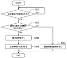
図2は、本実施形態に係る受電装置における状態管理方法に係る処理の一例を示す流れ図である。ここで、図2に示すステップS200、S202の処理が上記(I)の処理(判定処理)に該当し、図2に示すステップS204、S208の処理が上記(II)の処理(記録制御処理)に該当する。また、図2に示すステップS206の処理が上記(III)の処理(課金処理)に該当する。 FIG. 2 is a flowchart illustrating an example of processing related to a state management method in the power receiving device according to the present embodiment. Here, the processes of steps S200 and S202 shown in FIG. 2 correspond to the process (I) (determination process), and the processes of steps S204 and S208 shown in FIG. 2 are the processes (II) (recording control process). It corresponds to. Further, the process of step S206 shown in FIG. 2 corresponds to the process (III) (billing process).
本実施形態に係る受電装置は、証拠情報が受信されたか否かを判定する(S200)。ステップS200において証拠情報が受信されたと判定されない場合には、本実施形態に係る受電装置は、証拠情報が受信されたと判定されるまで処理を進めない。 The power receiving device according to the present embodiment determines whether or not evidence information has been received (S200). If it is not determined in step S200 that evidence information has been received, the power receiving device according to the present embodiment does not proceed with processing until it is determined that evidence information has been received.
また、ステップS200において証拠情報が受信されたと判定された場合には、本実施形態に係る受電装置は、証拠情報に課金に関する情報が含まれるか否かを判定する(S202)。 If it is determined in step S200 that evidence information has been received, the power receiving apparatus according to the present embodiment determines whether the evidence information includes information related to charging (S202).
ステップS202において証拠情報に課金に関する情報が含まれると判定されない場合には、本実施形態に係る受電装置は、受信された証拠情報を記録媒体に記憶させる(S204)。そして、本実施形態に係る受電装置は、本実施形態に係る状態管理方法に係る処理を終了する。 If it is not determined in step S202 that the evidence information includes information related to charging, the power receiving apparatus according to the present embodiment stores the received evidence information in the recording medium (S204). And the power receiving apparatus which concerns on this embodiment complete | finishes the process which concerns on the state management method which concerns on this embodiment.
また、ステップS202において証拠情報に課金に関する情報が含まれると判定された場合には、本実施形態に係る受電装置は、課金処理を行う(S206)。 If it is determined in step S202 that the information related to charging is included in the evidence information, the power receiving apparatus according to the present embodiment performs charging processing (S206).
また、本実施形態に係る受電装置は、証拠情報を記録媒体に記憶させる(S208)。ここで、ステップS208において記録媒体に記憶される証拠情報は、例えば、受信された証拠情報であってもよいし、ステップS206の処理の結果に応じて本実施形態に係る受電装置により変更が加えられた証拠情報(例えば、課金が正常に完了したか否かを示す情報が付加された証拠情報)であってもよい。そして、本実施形態に係る受電装置は、本実施形態に係る状態管理方法に係る処理を終了する。 Further, the power receiving device according to the present embodiment stores the evidence information in the recording medium (S208). Here, the evidence information stored in the recording medium in step S208 may be received evidence information, for example, or may be changed by the power receiving device according to the present embodiment according to the result of the process in step S206. It may be the evidence information (for example, evidence information to which information indicating whether or not the billing has been normally completed is added). And the power receiving apparatus which concerns on this embodiment complete | finishes the process which concerns on the state management method which concerns on this embodiment.
本実施形態に係る受電装置は、状態管理方法に係る処理として、例えば図2に示す処理を行う。図2に示す処理によって、上記(I)の処理(判定処理)〜上記(III)の処理(課金処理)が実現される。よって、例えば図2に示す処理を行うことによって、本実施形態に係る受電装置は、給電が行われない状態となった場合における情報を、より確実に残すことができる。 The power receiving apparatus according to the present embodiment performs, for example, the process illustrated in FIG. 2 as the process related to the state management method. With the process shown in FIG. 2, the process (I) (determination process) to the process (III) (billing process) are realized. Therefore, for example, by performing the process illustrated in FIG. 2, the power receiving device according to the present embodiment can more reliably leave information in a case where power feeding is not performed.
なお、本実施形態に係る受電装置における状態管理方法に係る処理は、図2に示す処理に限られない。例えば、本実施形態に係る受電装置は、図2に示すステップS202、S206、S208の処理を行わないことも可能である。図2に示すステップS202、S206、S208の処理を行わない場合であっても、本実施形態に係る受電装置は、上記(I)の処理(判定処理)、および上記(II)の処理(記録制御処理)を実現することができる。よって、図2に示すステップS202、S206、S208の処理を行わない場合であっても、本実施形態に係る受電装置は、給電が行われない状態となった場合における情報を、より確実に残すことができる。 In addition, the process which concerns on the state management method in the power receiving apparatus which concerns on this embodiment is not restricted to the process shown in FIG. For example, the power receiving device according to the present embodiment may not perform the processes of steps S202, S206, and S208 illustrated in FIG. Even when the processes of steps S202, S206, and S208 shown in FIG. 2 are not performed, the power receiving device according to the present embodiment performs the process (I) (determination process) and the process (recording) (II). Control processing) can be realized. Therefore, even when the processes of steps S202, S206, and S208 illustrated in FIG. 2 are not performed, the power receiving device according to the present embodiment more reliably retains information when power is not supplied. be able to.
(本実施形態に係る通信)
次に、上述した本実施形態に係る状態管理方法に係る処理とに係る、給電装置(または、給電装置に接続された外部通信装置)と受電装置(給電装置からみた場合における、給電対象の外部装置)との間で行われる通信について説明する。以下では、本実施形態に係る給電装置と本実施形態に係る受電装置とが通信を行う場合を例に挙げて、本実施形態に係る通信について説明する。また、以下では、本実施形態に係る給電装置と本実施形態に係る受電装置とが電力線で接続される場合、すなわち、電力が電力線を介した有線で伝送される場合を例に挙げて、本実施形態に係る通信について説明する。
(Communication according to this embodiment)
Next, a power supply device (or an external communication device connected to the power supply device) and a power reception device (when viewed from the power supply device) related to the process related to the state management method according to the present embodiment described above Communication performed with the apparatus) will be described. Hereinafter, communication according to the present embodiment will be described by taking as an example a case where the power feeding device according to the present embodiment and the power receiving device according to the present embodiment perform communication. Also, in the following, the case where the power supply apparatus according to the present embodiment and the power receiving apparatus according to the present embodiment are connected by a power line, that is, the case where power is transmitted by wire via the power line is described as an example. Communication according to the embodiment will be described.
本実施形態に係る給電装置と本実施形態に係る受電装置との間で行われる通信としては、例えば、無線通信と、電力線通信(有線通信)とが挙げられる。 Examples of communication performed between the power supply apparatus according to the present embodiment and the power reception apparatus according to the present embodiment include wireless communication and power line communication (wired communication).
本実施形態に係る給電装置と本実施形態に係る受電装置との間では、例えば、NFC(Near Field Communication)による通信技術やRFID(Radio Frequency IDentification)技術などの無線通信技術を用いて、無線通信が行われる。また、本実施形態に係る給電装置と本実施形態に係る受電装置との間では、例えば、NFCによる通信技術やRFID技術などの無線通信技術を、有線通信に適用することによって、電力線通信が行われる。ここで、本実施形態に係る電力線通信には、例えば、各装置の端子が接触して行われる通信(いわゆる、接触通信)と、各装置の端子が有線で結ばれて行われる通信とが含まれる。 Between the power supply apparatus according to the present embodiment and the power receiving apparatus according to the present embodiment, for example, wireless communication using a wireless communication technique such as a communication technique using NFC (Near Field Communication) or an RFID (Radio Frequency IDentification) technique is used. Is done. Further, between the power supply apparatus according to the present embodiment and the power receiving apparatus according to the present embodiment, for example, wireless communication technology such as NFC communication technology or RFID technology is applied to wired communication, thereby performing power line communication. Is called. Here, the power line communication according to the present embodiment includes, for example, communication performed by contact of terminals of each device (so-called contact communication) and communication performed by connecting terminals of each device by wire. It is.
本実施形態に係る給電装置は、例えば、高周波信号を生成する高周波信号生成部(後述する)を備え、高周波信号を外部装置へ送信する。つまり、本実施形態に係る給電装置は、例えば、いわゆるリーダ/ライタ機能を有する。 The power supply device according to the present embodiment includes, for example, a high frequency signal generation unit (described later) that generates a high frequency signal, and transmits the high frequency signal to an external device. That is, the power supply apparatus according to the present embodiment has a so-called reader / writer function, for example.
また、本実施形態に係る受電装置は、例えば本実施形態に係る給電装置などの外部装置から送信された信号に基づいて負荷変調を行うことにより、当該外部装置と通信を行う。例えば、本実施形態に係る受電装置が、本実施形態に係る給電装置から送信された高周波信号を受信した場合には、受信した高周波信号から電力を得て駆動し、受信した高周波信号を処理した結果に基づいて負荷変調を行うことによって、高周波信号を送信する。 Moreover, the power receiving apparatus according to the present embodiment performs communication with the external apparatus by performing load modulation based on a signal transmitted from the external apparatus such as the power supply apparatus according to the present embodiment. For example, when the power receiving device according to the present embodiment receives a high-frequency signal transmitted from the power feeding device according to the present embodiment, the power receiving device is driven by obtaining power from the received high-frequency signal and processes the received high-frequency signal. A high frequency signal is transmitted by performing load modulation based on the result.
例えば、本実施形態に係る給電装置と本実施形態に係る受電装置とが、ぞれぞれ上記のような処理を行うことによって、本実施形態に係る給電装置と本実施形態に係る受電装置との間では、本実施形態に係る無線通信、または、本実施形態に係る電力線通信が実現される。 For example, the power feeding device according to the present embodiment and the power receiving device according to the present embodiment perform the above-described processes, respectively, so that the power feeding device according to the present embodiment and the power receiving device according to the present embodiment Between, wireless communication according to the present embodiment or power line communication according to the present embodiment is realized.
ここで、本実施形態に係る高周波信号としては、例えば、RFIDで用いられる周波数の信号や、非接触通信で用いられる周波数の信号などが挙げられる。例えば、高周波信号の周波数としては、130〜135[kHz]、13.56[MHz]、56[MHz]、433[MHz]、954.2[MHz]、954.8[MHz]、2441.75[MHz]、2448.875[MHz]が挙げられるが、本実施系形態に係る高周波信号の周波数は、上記に限られない。以下では、本実施形態に係る高周波信号に基づき送信される高周波を、「搬送波」と示す場合がある。 Here, examples of the high-frequency signal according to the present embodiment include a frequency signal used in RFID and a frequency signal used in non-contact communication. For example, the frequency of the high-frequency signal is 130 to 135 [kHz], 13.56 [MHz], 56 [MHz], 433 [MHz], 954.2 [MHz], 954.8 [MHz], 2441.75. [MHz] and 2448.875 [MHz] are mentioned, but the frequency of the high-frequency signal according to the present embodiment is not limited to the above. Hereinafter, the high frequency transmitted based on the high frequency signal according to the present embodiment may be referred to as “carrier wave”.
なお、本実施形態に係る無線通信と、本実施形態に係る電力線通信とは、NFCによる通信技術やRFID技術などの無線通信技術を用いた通信に限られない。例えば、本実施形態に係る給電装置と本実施形態に係る受電装置との間では、IEEE802.11bに基づく無線通信などの任意の方式の無線通信や、PLC(Power Line Communication。電力線搬送通信)などの電力線通信が行われてもよい。以下では、本実施形態に係る給電装置と本実施形態に係る受電装置との間において、NFCによる通信技術やRFID技術などの無線通信技術を用いた通信が行われる場合を例に挙げて、本実施形態に係る通信について説明する。 Note that the wireless communication according to the present embodiment and the power line communication according to the present embodiment are not limited to communication using wireless communication technology such as NFC communication technology or RFID technology. For example, between the power feeding apparatus according to the present embodiment and the power receiving apparatus according to the present embodiment, wireless communication of an arbitrary system such as wireless communication based on IEEE802.11b, PLC (Power Line Communication), etc. Power line communication may be performed. Hereinafter, the case where communication using a wireless communication technology such as NFC communication technology or RFID technology is performed between the power supply device according to the present embodiment and the power reception device according to the present embodiment will be described as an example. Communication according to the embodiment will be described.
[1]本実施形態に係る無線通信
まず、本実施形態に係る無線通信について説明する。図3は、本実施形態に係る無線通信の一例を説明するための説明図である。以下では、図3に示す給電装置100Aと、受電装置200Aとを例に挙げて、本実施形態に係る無線通信について説明する。なお、図3では、本実施形態に係る給電装置の構成と本実施形態に係る受電装置の構成とのうち、本実施形態に係る無線通信に係る構成要素を示している。また、図3では、受電装置200Aとして、プラグを示しているが、本実施形態に係る受電装置は、プラグに限られない。
[1] Wireless communication according to this embodiment First, wireless communication according to this embodiment will be described. FIG. 3 is an explanatory diagram for explaining an example of wireless communication according to the present embodiment. Hereinafter, the wireless communication according to the present embodiment will be described using the
給電装置100Aは、例えば、接続部102と、無線通信部104と、制御部106とを備える。また、受電装置200Aは、例えば、接続部202と、無線通信部204とを備える。
The
接続部102は、電力が伝送される電力線PLを、外部装置に接続させる。また、接続部102には、接続される外部装置の接続状態の維持を補助するための接続補助部材が備えられていてもよい。ここで、本実施形態に係る電力線PLとしては、例えば、50[Hz]や60[Hz]などの所定の周波数の交流電流や、直流電流が流れる電力線が挙げられる。また、本実施形態に係る接続補助部材としては、例えば、マグネットなどが挙げられる。以下では、電力線PLに所定の周波数の交流電流が流れる場合を例に挙げて、説明する。
より具体的には、接続部102は、電力線PLと接続された端子を有し、また、接続部202は、電力線PL(給電装置100Aからみた場合には、外部電力線に該当する。)と接続された端子を有する。そして、接続部102が有する端子と、接続部202が有する端子とが、電気的に接続されることによって、給電装置100Aと受電装置200A(給電装置100Aからみた場合には、外部装置に該当する。)とは、接続される。ここで、本実施形態に係る“接続部102が有する端子と接続部202が有する端子との電気的な接続”とは、例えば、各装置の接続部が有する端子が接触することや、各装置の接続部が有する端子が有線で結ばれることをいう。なお、接続部202には、給電装置100Aが備える接続部102と同様に、接続される外部装置の接続状態の維持を補助するための接続補助部材が備えられていてもよい。
More specifically,
また、接続部102は、例えば、外部装置の接続状態の変化(未接続状態から接続状態への変化/接続状態から未接続状態への変化)を検出する。そして、接続部102は、検出されたこと(検出結果)を示す検出信号を、制御部106へ伝達する。なお、無線通信部104が、検出信号の伝達に応じて高周波信号を送信する機能を有している構成である場合には、接続部102は、検出信号を無線通信部104へ伝達してもよい。また、接続部102は、例えば、本実施形態に係る給電装置が備える電力供給部(後述する)に、検出信号を伝達してもよい。
Further, the
ここで、接続部102は、例えば、外部装置の物理的な接続状態を検出するスイッチを備え、当該スイッチの状態が変化したときに検出信号を制御部106などに伝達するが、接続部102の構成は、上記に限られない。例えば、本実施形態に係る接続部102は、圧力センサや加速度センサなどの1または2以上のセンサを備え、センサの検出結果に基づく検出信号を制御部106などに伝達してもよい。例えば、接続部102が圧力センサを備える場合、所定の閾値以上(または所定の閾値より大きな)の圧力が検出されているときの検出信号が外部装置が接続されている接続状態を示し、所定の閾値以上(または所定の閾値より大きな)の圧力が検出されていないときの検出信号が、外部装置が接続されていない未接続状態を示す。また、例えば、接続部102が加速度センサを備える場合、所定の閾値以上(または所定の閾値より大きな)の加速度が検出されたときの検出信号が示す、加速度の方向によって、接続状態と未接続状態とがそれぞれ示される。
Here, the
なお、例えば、給電装置100Aが定期的/非定期的に高周波信号を送信する構成である場合や、給電装置100Aが上述した第2の例に係る判定処理(電力線の接続状態に基づく判定処理)を行わない構成である場合には、本実施形態に係る接続部102は、例えば外部装置の接続状態の変化の検出に係る機能を有していない構成をとることも可能である。
For example, when the
無線通信部104と、無線通信部204とは、本実施形態に係る無線通信を行う役目を果たす。また、無線通信部104における通信は、例えば、制御部106によって制御する。
The
制御部106は、MPU(Micro Processing Unit)や各種処理回路が集積された集積回路などで構成され、給電装置100Aの各部を制御する。より具体的には、制御部106は、例えば、接続部102から伝達される検出信号や、無線通信部104から伝達される受電装置200Aなどの外部装置からの応答信号に基づいて、高周波信号生成命令や、高周波信号送信停止命令を無線通信部104に対して伝達して、無線通信部104における通信を制御する。
The
また、制御部106は、本実施形態に係る状態管理方法に係る処理(例えば、上記(1)の処理(判定処理)〜上記(3)の処理(送信制御処理))を主導的に行う役目を果たす。本実施形態に係る給電装置が備える制御部106における、本実施形態に係る状態管理方法に係る処理を実現するための構成の一例については、後述する。
In addition, the
図4は、本実施形態に係る給電装置と本実施形態に係る受電装置との間で行われる無線通信を実現するための構成の一例を示す説明図である。ここで、図4では、図3に示す給電装置100Aが備える無線通信部104、および制御部106と、図3に示す受電装置200Aが備える無線通信部204との構成の一例を示している。
FIG. 4 is an explanatory diagram illustrating an example of a configuration for realizing wireless communication performed between the power feeding device according to the present embodiment and the power receiving device according to the present embodiment. Here, FIG. 4 illustrates an example of a configuration of the
〔1−1〕本実施形態に係る給電装置が備える無線通信部104
無線通信部104は、例えば、高周波信号生成部150と、高周波送信部152と、復調部154とを備える。また、無線通信部104は、例えば、制御部106から伝達される高周波信号生成命令に応じて高周波信号を送信し、制御部106から伝達される高周波信号送信停止命令に応じて、高周波信号の送信を停止する。
[1-1] The
The
また、無線通信部104は、例えば、通信を暗号化するための暗号化回路(図示せず)や、通信衝突防止(アンチコリジョン)回路、外部装置や他の回路と接続するための接続インタフェース(図示せず)などを備えてもよい。ここで、無線通信部104は、例えば、データの伝送路としてのバスにより各構成要素間を接続する。また、接続インタフェースとしては、例えば、UART(Universal Asynchronous Receiver Transmitter)や、LAN端子および送受信回路などが挙げられる。
In addition, the
高周波信号生成部150は、制御部106からの高周波信号生成命令を受け、高周波信号生成命令に応じた高周波信号を生成する。ここで、図4では、高周波信号生成部150として交流電源が示されているが、本実施形態に係る高周波信号生成部150は、上記に限られない。例えば、本実施形態に係る高周波信号生成部150は、ASK(Amplitude Shift Keying)変調する変調回路(図示せず)と、変調回路の出力を増幅する増幅回路(図示せず)とで構成することができる。
The high frequency
ここで、高周波信号生成部150が生成する高周波信号としては、例えば、外部装置に識別情報の送信を要求する識別情報送信要求が含まれる高周波信号や、外部装置に対する各種処理命令や処理するデータを含む高周波信号が挙げられる。なお、高周波信号生成部150が生成する高周波信号は、上記に限られない。例えば、本実施形態に係る高周波信号は、後述する受電装置200Aの電力線通信部208に対して電力供給を行う役目を果たす信号(例えば、無変調の信号)であってもよい。
Here, the high-frequency signal generated by the high-frequency
高周波送信部152は、例えば、所定のインダクタンスをもつコイル(インダクタ。以下、同様とする。)L1を備え、高周波信号生成部150が生成した高周波信号に応じた搬送波を送信する。また、高周波送信部152は、外部装置からの応答信号を受信することもできる。つまり、高周波送信部152は、無線通信部104の通信アンテナとしての役目を果たすことができる。ここで、図4では、高周波送信部152がコイルL1で構成されている例を示しているが、本実施形態に係る高周波送信部152の構成は、上記に限られない。例えば、本実施形態に係る高周波送信部は、さらにキャパシタを備えることにより共振回路を構成してもよい。
The high-
復調部154は、例えば、高周波送信部152のアンテナ端における電圧の振幅変化を包絡線検波し、検波した信号を2値化することによって、外部装置からの応答信号を復調する。なお、復調部154における応答信号の復調手段は、上記に限られない、例えば、復調部154は、高周波送信部152のアンテナ端における電圧の位相変化を用いて応答信号を復調することもできる。
For example, the
また、復調部154は、復調した応答信号を制御部106へ伝達する。そして、復調された応答信号が伝達された制御部106は、例えば、応答信号に対応するデータを処理する、処理結果に基づいて高周波信号生成命令を生成するなど、様々な処理を行う。
Further, the
無線通信部104は、例えば図4に示す構成によって、搬送波を送信し、受電装置200Aなどの外部装置から送信される応答信号を復調する。なお、本実施形態に係る無線通信部104の構成が、図4に示す構成に限られないことは、言うまでもない。
For example, with the configuration illustrated in FIG. 4, the
〔1−2〕本実施形態に係る受電装置が備える無線通信部204
無線通信部204は、通信アンテナ250と、ICチップ252とを備える。また、無線通信部204は、例えば、データの伝送路としてのバス272で各構成要素間を接続する。
[1-2]
The
通信アンテナ250は、給電装置100Aなどの外部装置から送信された搬送波を受信し、ICチップ252における処理の処理結果に基づく応答信号を送信する。
The
通信アンテナ250は、例えば、所定のインダクタンスをもつコイル(インダクタ)L2と、所定の静電容量をもつキャパシタC1とからなる共振回路で構成され、搬送波の受信に応じて電磁誘導により誘起電圧を生じさせる。そして、通信アンテナ250は、所定の共振周波数で誘起電圧を共振させた受信電圧を出力する。ここで、通信アンテナ250における共振周波数は、例えば、13.56[MHz]など搬送波の周波数に合わせて設定される。通信アンテナ250は、上記構成により、搬送波を受信し、また、ICチップ252が備える負荷変調部264(後述する)において行われる負荷変調によって応答信号の送信を行う。
For example, the
ICチップ252は、受信された搬送波に基づいて高周波信号を復調して処理し、負荷変調により応答信号を通信アンテナ250から送信させる。つまり、ICチップ252は、無線通信部204において、無線通信を主導的に行う実質的な無線通信部としての役目を果たす。
The
ICチップ252は、例えば、キャリア検出部254と、検波部256と、レギュレータ258と、復調部260と、データ処理部262と、負荷変調部264と、ROM(Read Only Memory)266と、RAM(Random Access Memory)268と、内部メモリ270とを備える。また、データ処理部262と、ROM266、RAM268、内部メモリ270とは、例えば、データの伝送路としてのバス272によって接続される。なお、図4では示していないが、ICチップ252は、例えば、過電圧や過電流がデータ処理部262に印加されることを防止するための保護回路(図示せず)をさらに備えていてもよい。ここで、保護回路(図示せず)としては、例えば、ダイオードなどで構成されたクランプ回路が挙げられる。
The
キャリア検出部254は、通信アンテナ250から伝達される受信電圧に基づいて、例えば、矩形の検出信号を生成し、当該検出信号をデータ処理部262へ伝達する。また、データ処理部262は、伝達される上記検出信号を、例えば、データ処理のための処理クロックとして用いる。ここで、上記検出信号は、通信アンテナ250から伝達される受信電圧に基づくものであるので、外部装置から送信される搬送波の周波数と同期することとなる。したがって、ICチップ252は、キャリア検出部254を備えることによって、外部装置との間の処理を、外部装置と同期して行うことができる。
The
検波部256は、通信アンテナ250から出力される受信電圧を整流する。ここで、検波部256は、例えば、ダイオードD1と、キャパシタC2とで構成される。
The
レギュレータ258は、受信電圧を平滑、定電圧化し、データ処理部262へ駆動電圧を出力する。ここで、レギュレータ258は、例えば、受信電圧の直流成分を駆動電圧として用いる。
The
復調部260は、受信電圧に基づいて高周波信号を復調し、搬送波に含まれる高周波信号に対応するデータ(例えば、ハイレベルとローレベルとの2値化されたデータ信号)を出力する。ここで、復調部260は、例えば、受信電圧の交流成分をデータとして出力する。
The
データ処理部262は、例えば、レギュレータ258から出力される駆動電圧を電源として駆動し、復調部260において復調されたデータの処理を行う。ここで、データ処理部262は、例えば、MPUや各種処理回路などで構成される。
For example, the
また、データ処理部262は、外部装置への応答に係る負荷変調を制御する制御信号を処理結果に応じて選択的に生成する。そして、データ処理部262は、制御信号を負荷変調部264へと選択的に出力する。
Further, the
また、データ処理部262は、例えば、復調部260において復調されたデータに含まれる命令に基づいて、内部メモリ270に記憶されたデータの読出し、更新などを行う。
In addition, the
負荷変調部264は、例えば、負荷ZとスイッチSW1とを備え、データ処理部262から伝達される制御信号に応じて負荷Zを選択的に接続する(有効化する)ことによって負荷変調を行う。ここで、負荷Zは、例えば、所定の抵抗値を有する抵抗で構成されるが、負荷Zは、上記に限られない。また、スイッチSW1は、例えば、pチャネル型のMOSFET(Metal Oxide Semiconductor Field Effect Transistor)や、nチャネル型のMOSFETで構成されるが、スイッチSW1は、上記に限られない。
The
ROM266は、データ処理部262が使用するプログラムや演算パラメータなどの制御用データを記憶する。RAM268は、データ処理部262により実行されるプログラムや、演算結果、実行状態などを一時的に記憶する。
The
内部メモリ270は、ICチップ252が備える記憶手段であり、例えば耐タンパ性を有し、データ処理部262によって、例えば、データの読出しや、データの新規書込み、データの更新が行われる。内部メモリ270には、例えば、識別情報や、電子バリュー、アプリケーションなど様々なデータが記憶される。ここで、図4では、内部メモリ270が識別情報274と電子バリュー276とを記憶している例を示しているが、内部メモリ270に記憶されるデータは、上記に限られない。
The
ICチップ252は、例えば図4に示す上記のような構成によって、通信アンテナ250が受信した高周波信号を処理し、負荷変調によって通信アンテナ250から応答信号を送信させる。
The
無線通信部204は、例えば、通信アンテナ250と、ICチップ252とを備えることによって、給電装置100Aなどの外部装置から送信された高周波信号を処理し、負荷変調により応答信号を送信させる。なお、本実施形態に係る無線通信部204の構成は、図4に示す構成に限られない。例えば、無線通信部204は、例えば図4に示すICチップ252を構成する各構成要素を、IC(Integrated Circuit)チップの形態で備えていなくてもよい。
For example, the
本実施形態に係る給電装置と、本実施形態に係る受電装置とは、例えば、図4に示す無線通信部104を本実施形態に係る給電装置が備え、図4に示す無線通信部204を本実施形態に係る受電装置が備えることによって、NFCによる通信技術などの無線通信技術を用いて、無線通信を行うことができる。
The power supply apparatus according to the present embodiment and the power reception apparatus according to the present embodiment include, for example, the
ここで、NFCによる通信技術やRFID技術などの無線通信技術により無線通信を行うことによって、本実施形態に係る受電装置は、受信した高周波信号から電力を得て駆動し、負荷変調を行うことにより記憶している情報を送信することができる。つまり、本実施形態に係る給電装置と本実施形態に係る受電装置とを有する通信システムでは、本実施形態に係る受電装置は、通信を行うための別途の電源回路を備えなくとも、無線で通信を行うことが可能である。また、本実施形態に係る受電装置は、例えば、ユーザ操作に応じた信号(ユーザの指示を示す信号)が入力されなくとも、負荷変調を行うことにより記憶している情報を送信することができる。 Here, by performing wireless communication using wireless communication technology such as NFC communication technology or RFID technology, the power receiving device according to the present embodiment obtains power from the received high-frequency signal and drives and modulates the load. The stored information can be transmitted. In other words, in a communication system having the power supply device according to the present embodiment and the power receiving device according to the present embodiment, the power receiving device according to the present embodiment communicates wirelessly even if it does not include a separate power supply circuit for performing communication. Can be done. Moreover, the power receiving apparatus according to the present embodiment can transmit stored information by performing load modulation, for example, even if a signal corresponding to a user operation (a signal indicating a user instruction) is not input. .
[2]本実施形態に係る電力線通信
次に、本実施形態に係る電力線通信について説明する。図5は、本実施形態に係る電力線通信の一例を説明するための説明図である。以下では、図5に示す給電装置100Bと、受電装置200Bとを例に挙げて、本実施形態に係る電力線通信について説明する。なお、図5では、本実施形態に係る給電装置の構成と本実施形態に係る受電装置の構成とのうち、本実施形態に係る電力線通信に係る構成要素を示している。なお、本実施形態に係る受電装置における電力線通信に係る構成要素は、例えば図3に示す受電装置200Aのように、プラグに設けられていてもよい。
[2] Power Line Communication According to this Embodiment Next, power line communication according to this embodiment will be described. FIG. 5 is an explanatory diagram for explaining an example of power line communication according to the present embodiment. Hereinafter, the power line communication according to the present embodiment will be described using the
〔2−1〕給電装置100B
給電装置100Bは、例えば、接続部102と、制御部106と、電力線通信部108と、第1フィルタ110(通信フィルタ)と、第2フィルタ112とを備える。
[2-1]
The
また、給電装置100Bは、例えば、ROM(図示せず)や、RAM(図示せず)、記憶部(図示せず)、表示部(図示せず)などを備えていてもよい。給電装置100Bは、例えば、データの伝送路としてのバスにより各構成要素間を接続する。ここで、ROM(図示せず)は、制御部106が使用するプログラムや演算パラメータなどの制御用データを記憶する。RAM(図示せず)は、制御部106により実行されるプログラムなどを一時的に記憶する。
The
記憶部(図示せず)は、給電装置100Bが備える記憶手段であり、受電装置200Bなどの外部装置から取得した識別情報や、送信先情報、アプリケーションなど、様々なデータを記憶する。ここで、記憶部(図示せず)としては、例えば、ハードディスクなどの磁気記録媒体や、EEPROM(Electrically Erasable and Programmable Read Only Memory)、フラッシュメモリ(flash memory)、MRAM(Magnetoresistive Random Access Memory)、FeRAM(Ferroelectric Random Access Memory)、PRAM(Phase change Random Access Memory)などの不揮発性メモリ(nonvolatile memory)などが挙げられる。また、記憶部(図示せず)は、給電装置100Bから着脱可能であってもよい。
The storage unit (not shown) is a storage unit included in the
表示部(図示せず)は、給電装置100Bが備える表示手段であり、表示画面に様々な情報(例えば、画像、および/または、文字など)を表示する。表示部(図示せず)の表示画面に表示される画面としては、例えば所望する動作を給電装置100Bに対して行わせるための操作画面などが挙げられる。
The display unit (not shown) is a display unit included in the
ここで、表示部(図示せず)としては、例えば、液晶ディスプレイ(Liquid Crystal Display)や有機ELディスプレイ(Organic Electro-Luminescence display。または、OLEDディスプレイ(Organic Light Emitting Diode display)ともよばれる。)などの表示デバイスが挙げられる。また、給電装置100Bは、例えばタッチスクリーンで表示部(図示せず)を構成することもできる。上記の場合には、表示部(図示せず)は、ユーザ操作および表示の双方が可能な操作表示部として機能することとなる。
Here, as the display unit (not shown), for example, a liquid crystal display (Liquid Crystal Display), an organic EL display (Organic Electro-Luminescence display, or an OLED display (Organic Light Emitting Diode display)) is used. Display devices. In addition, the
なお、給電装置100Bは、表示部(図示せず)を備えているか否かによらず、ネットワークを介して(または直接的に)外部端末と通信を行い、当該外部端末の表示画面に上記操作画面や様々な情報を表示させることもできる。例えば、上記外部端末が給電装置100Bのユーザが所有する外部端末(例えば、携帯型通信装置やリモート・コントローラなど)である場合には、ユーザは、自己が所有する外部端末を操作して給電装置100Bに所望の処理を行わせることができ、また、当該外部端末を用いて給電装置100Bから送信される情報を確認することができる。よって、上記の場合には、例えば給電装置100Bが机の下に設置されているときなど、ユーザが給電装置100Bを直接操作したり、表示部(図示せず)に表示された情報をみることが容易ではないときであっても、ユーザの利便性の向上を図ることができる。
Regardless of whether or not the
制御部106は、MPUや各種処理回路が集積された集積回路などで構成され、給電装置100Bの各部を制御する。より具体的には、制御部106は、例えば、接続部102から伝達される検出信号や、電力線通信部108から伝達される受電装置200Bなどの外部装置からの応答信号に基づいて、高周波信号生成命令や、高周波信号送信停止命令を電力線通信部108に対して伝達して、電力線通信部108における通信を制御する。制御部106が、上記検出信号に基づいて高周波信号生成命令や、高周波信号送信停止命令を電力線通信部108に対して伝達することによって、実際に電力線を介して接続されている外部装置と通信を行うことができる。
The
制御部106が、上記のように高周波信号生成命令や高周波信号送信停止命令を電力線通信部108に対して伝達することによって、電力線通信部108は、例えば、接続部102における検出結果に基づいて高周波信号を送信することが可能となる。また、制御部106が、上記応答信号に基づいて高周波信号生成命令や、高周波信号送信停止命令を電力線通信部108に対して伝達することによって、受電装置200Bなどの外部装置との間の電力線を介した通信を制御することができる。なお、制御部106は、例えば、定期的/非定期的に高周波信号生成命令を電力線通信部108に対して伝達することによって、電力線通信部108に高周波信号を定期的/非定期的に送信させてもよい。
The
また、制御部106は、上述したように、本実施形態に係る状態管理方法に係る処理(例えば、上記(1)の処理(判定処理)〜上記(3)の処理(送信制御処理))を主導的に行う役目を果たす。本実施形態に係る給電装置が備える制御部106における、本実施形態に係る状態管理方法に係る処理を実現するための構成の一例については、後述する。
Further, as described above, the
電力線通信部108は、電力線を介して受電装置200Bなどの外部装置との間で通信を行う役目を果たす。
The power
図6は、本実施形態に係る給電装置100Bが備える電力線通信部108の構成の一例を示す説明図である。ここで、図6では、制御部106と第1フィルタ110とを併せて示している。電力線通信部108は、例えば、高周波信号生成部156と、復調部158とを備え、NFCなどにおけるリーダ/ライタ(または質問器)としての役目を果たす。また、電力線通信部108は、例えば、暗号化回路(図示せず)や通信衝突防止(アンチコリジョン)回路などをさらに備えてもよい。
FIG. 6 is an explanatory diagram illustrating an example of the configuration of the power
高周波信号生成部156は、例えば制御部106から伝達される高周波信号生成命令を受け、高周波信号生成命令に応じた高周波信号を生成する。また、高周波信号生成部156は、例えば制御部106から伝達される、高周波信号の送信停止を示す高周波信号送信停止命令を受け、高周波信号を生成を停止する。ここで、図6では、高周波信号生成部156として交流電源が示されているが、本実施形態に係る高周波信号生成部156は、上記に限られない。例えば、本実施形態に係る高周波信号生成部132は、ASK変調を行う変調回路(図示せず)と、変調回路の出力を増幅する増幅回路(図示せず)とを備えることができる。
The high frequency
ここで、高周波信号生成部156が生成する高周波信号としては、例えば、外部装置に識別情報の送信を要求する識別情報送信要求が含まれる高周波信号や、外部装置に対する各種処理命令や処理するデータを含む高周波信号が挙げられる。なお、高周波信号生成部156が生成する高周波信号は、上記に限られない。例えば、本実施形態に係る高周波信号は、後述する受電装置200Bの電力線通信部208に対して電力供給を行う役目を果たす信号(例えば、無変調の信号)であってもよい。
Here, as the high-frequency signal generated by the high-frequency
復調部158は、例えば、高周波信号生成部156と第1フィルタ110との間における電圧の振幅変化を包絡線検波し、検波した信号を2値化することによって、外部装置から送信される応答信号を復調する。そして、復調部158は、復調した応答信号(例えば、識別情報を示す応答信号や、高調波信号に応じた処理に基づく応答を示す応答信号)を、制御部106へ伝達する。なお、復調部158における応答信号の復調手段は、上記に限られず、例えば、復調部158は、高周波信号生成部156と第1フィルタ110との間における電圧の位相変化を用いて応答信号を復調することもできる。
For example, the
本実施形態に係る電力線通信部108は、例えば図6に示す構成によって、NFCなどにおけるリーダ/ライタとしての役目を果たし、電力線を介して外部装置との間で通信を行う役目を果たすことができる。
The power
なお、本実施形態に係る電力線通信部108の構成は、図6に示す構成に限られない。図7は、本実施形態に係る給電装置100Bが備える電力線通信部108の他の例を示す説明図である。ここで、図7では、図6と同様に、制御部106と第1フィルタ110とを併せて示している。
The configuration of the power
他の例に係る電力線通信部108は、高周波信号生成部156と、復調部158と、第1高周波送受信部160と、第2高周波送受信部162とを備える。また、他の例に係る電力線通信部108は、例えば、暗号化回路(図示せず)や通信衝突防止(アンチコリジョン)回路などをさらに備えてもよい。
The power
高周波信号生成部156は、図6に示す高周波信号生成部156と同様に、高周波信号生成命令に応じた高周波信号を生成し、高周波信号送信停止命令に応じて高周波信号の生成を停止する。
The high-frequency
復調部158は、高周波信号生成部156のアンテナ端における電圧の振幅変化を包絡線検波し、検波した信号を2値化することによって、外部装置から送信される応答信号を復調する。なお、復調部158における応答信号の復調手段は、上記に限られず、復調部158は、例えば、高周波信号生成部156のアンテナ端における電圧の位相変化を用いて応答信号を復調することもできる。
The
第1高周波送受信部160は、例えば、所定のインダクタンスをもつコイル(インダクタ)L3と所定の静電容量を有するキャパシタC3とを備え、共振回路を構成する。ここで、第1高周波送受信部156の共振周波数としては、例えば、13.56[MHz]などの高周波信号の周波数が挙げられる。第1高周波送受信部160は、上記構成により、高周波信号生成部156が生成した高周波信号を送信し、また、第2高周波送受信部162から送信される、外部装置から送信された応答信号を受信することができる。つまり、第1高周波送受信部160は、電力線通信部108内における第1の通信アンテナとしての役目を果たす。
The first high frequency transmitting / receiving
第2高周波送受信部162は、例えば、所定のインダクタンスをもつコイルL4と所定の静電容量を有するキャパシタC4とを備え、共振回路を構成する。ここで、第2高周波送受信部162の共振周波数としては、例えば、13.56[MHz]などの高周波信号の周波数が挙げられる。第2高周波送受信部162は、上記構成により、第1高周波送受信部160から送信された高周波信号を受信し、また、外部装置から送信された応答信号を送信することができる。つまり、第2高周波送受信部162は、電力線通信部108内における第2の通信アンテナとしての役目を果たす。
The second high frequency transmitter /
本実施形態に係る電力線通信部108は、図7に示す構成であっても、図6に示す構成と同様に、NFCなどにおけるリーダ/ライタとしての役目を果たし、電力線を介して外部装置との間で通信を行う役目を果たすことができる。
Even if the power
再度図5を参照して、本実施形態に係る給電装置100Bにおける、本実施形態に係る電力線通信に係る構成の一例について説明する。第1フィルタ110は、電力線通信部108と電力線PLとの間に接続され、電力線PLから伝達される信号をフィルタリングする役目を果たす。より具体的には、第1フィルタ110は、電力線PLから伝達される信号のうち、少なくとも電力線を介して受電装置200Bなどの外部装置に供給される電力の周波数の信号を遮断し、高周波信号を遮断しない機能を有する。給電装置100Bは、第1フィルタ110を備えることによってノイズとなりうる電力の周波数の信号を電力線通信部108へ伝達しないので、電力線通信部108と外部装置(より厳密には、例えば後述する受電装置200Bの電力線通信部208のような、外部装置が備える電力線通信部)との間の通信の精度を向上させることができる。
With reference to FIG. 5 again, an example of the configuration related to the power line communication according to the present embodiment in the
図8は、本実施形態に係る給電装置100Bが備える第1フィルタ110の構成の一例を示す説明図である。第1フィルタ110は、コイルL5、L6と、キャパシタC5〜C7と、サージアブソーバSA1〜SA3とで構成される。なお、本実施形態に係る第1フィルタ110の構成が、図8に示す構成に限られないことは、言うまでもない。
FIG. 8 is an explanatory diagram illustrating an example of the configuration of the
再度図5を参照して、本実施形態に係る給電装置100Bにおける、本実施形態に係る電力線通信に係る構成の一例について説明する。第2フィルタ112は、接続部102と電源との間の電力線PL上に設けられ、接続部102側から伝達されうる信号をフィルタリングする役目を果たす。ここで、本実施形態に係る電源としては、例えば、商用電源などの外部電源や、バッテリなどの内部電源などが挙げられる。
With reference to FIG. 5 again, an example of the configuration related to the power line communication according to the present embodiment in the
より具体的には、第2フィルタ112は、少なくとも電力線通信部108が送信する高周波信号や、外部装置により送信される高周波信号を遮断し、外部装置に供給される電力の周波数の信号を遮断しない機能を有する。給電装置100Bは、第2フィルタ112を備えることによって、例えば、電力線を介した通信に係る高周波信号や、外部装置側から伝達されうる雑音成分などの雑音成分を遮断することができる。つまり、第2フィルタ112は、いわゆるパワースプリッタとしての役目を果たす。
More specifically, the
図9は、本実施形態に係る給電装置100Bが備える第2フィルタ112の構成の一例を示す説明図である。第2フィルタ112は、コイルL7、L8と、キャパシタC8と、サージアブソーバSA4とで構成される。なお、本実施形態に係る第2フィルタ112の構成が、図9に示す構成に限られないことは、言うまでもない。
FIG. 9 is an explanatory diagram illustrating an example of the configuration of the
本実施形態に係る給電装置100Bは、例えば図5に示す構成によって、接続部102に接続された、受電装置200Bなどの外部装置と、電力線を介して通信を行うことができる。また、本実施形態に係る給電装置100Bは、例えば図5に示す構成によって、例えば、識別情報の送信や、電子バリューを用いた課金処理など、送信した高周波信号に基づく所定の処理を当該外部装置に行わせることができる。
The
〔2−2〕受電装置200B
受電装置200Bは、例えば、接続部202と、第1フィルタ206と、電力線通信部208と、第2フィルタ210とを備える。
[2-2]
The
また、受電装置200Bは、例えば、第2フィルタ210の後段(図5に示す第2フィルタ210における給電装置100Bと反対側)に、例えば、バッテリ(図示せず)や、受電装置200Bが有する機能を実現するための各種デバイス(例えば、MPUや、各種処理回路、駆動デバイスなど。図示せず)などを備える。つまり、受電装置200Bは、例えば、給電装置100Bなどの外部装置から電力線を介して供給される電力を上記バッテリ(図示せず)に充電することができ、また、当該供給される電力を用いて受電装置200Bが有する機能を実現することができる。例えば、受電装置200Bが、電気自動車などの車両である場合には、受電装置200Bは、電力供給を受けて内蔵するバッテリを充電し、バッテリの電力を使って車輪を回転させる。また、受電装置200Bが、画像(動画像/静止画像)および/または文字を表示することが可能な表示デバイスを備える場合には、受電装置200Bは、電力供給を受けて、表示デバイスの表示画面に、画像や文字を表示させる。
In addition, the
第1フィルタ206は、電力線(厳密には、受電装置200B内の電力線PL)と電力線通信部208との間に接続され、電力線から伝達される信号をフィルタリングする役目を果たす。より具体的には、第1フィルタ206は、電力線から伝達される信号のうち、少なくとも電力の周波数の信号を遮断し、高周波信号を遮断しない機能を有する。受電装置200Bは、第1フィルタ206を備えることによってノイズとなりうる電力の周波数の信号を電力線通信部208へ伝達しないので、電力線通信部208と外部装置(より厳密には、例えば給電装置100Bの電力線通信部108のような、外部装置が備える電力線通信部)との間の通信の精度を向上させることができる。
The
ここで、第1フィルタ206は、例えば図8に示す給電装置100Bの第1フィルタ110と同様の構成をとる。なお、本実施形態に係る第1フィルタ206の構成が、図8に示す構成に限られないことは、言うまでもない。
Here, the
電力線通信部208は、高周波信号によって、給電装置100Bなどの外部装置と電力線を介して通信を行う。より具体的には、電力線通信部208は、例えば、外部装置から送信された高周波信号を受信した場合には、当該高周波信号から電力を得て駆動して、受信した高周波信号に基づく処理を行う。そして、電力線通信部208は、上記処理に応じた応答信号を、負荷変調によって高周波信号として送信する。
The power
例えば、電力線通信部208は、識別情報の送信を要求する識別情報送信要求を含む高周波信号を受信した場合には、高周波信号に含まれる識別情報送信要求に基づいて、記憶されている識別情報を読み出す。そして、電力線通信部208は、読み出された識別情報を負荷変調によって電力線に重畳させて送信する。また、電力線通信部208は、例えば、各種処理命令や処理するデータを含む高周波信号を受信した場合には、高周波信号に含まれる処理命令やデータに基づく処理を行う。そして、電力線通信部208は、上記処理に基づく応答信号を負荷変調によって電力線に重畳させて送信する。つまり、電力線通信部208は、例えば、NFCなどにおける応答器としての役目を果たす。
For example, when the power
図10は、本実施形態に係る受電装置200Bが備える電力線通信部208の構成の一例を示す説明図である。ここで、図10では、第1フィルタ206を併せて示している。また、図10では、電力線通信部208が、受信された高調波信号を復調して処理し、負荷変調により応答信号を送信させるICチップ280を備える構成を示している。なお、本実施形態に係る電力線通信部208は、図10に示すICチップ280を構成する各構成要素を、ICチップの形態で備えていなくてもよい。
FIG. 10 is an explanatory diagram illustrating an example of a configuration of the power
ICチップ280は、例えば、検出部254と、検波部256と、レギュレータ258と、復調部260と、データ処理部262と、負荷変調部264とを備える。なお、図10では示していないが、ICチップ280は、例えば、過電圧や過電流がデータ処理部262に印加されることを防止するための保護回路(図示せず)をさらに備えていてもよい。ここで、保護回路(図示せず)としては、例えば、ダイオードなどで構成されたクランプ回路が挙げられる。
The
また、ICチップ280は、例えば、ROM234と、RAM236と、内部メモリ238とを備える。データ処理部262と、ROM234、RAM236、内部メモリ238とは、例えば、データの伝送路としてのバス240によって接続される。
The
ここで、図10に示すICチップ280の構成と、上述した本実施形態に係る無線通信に係る、図4に示す無線通信部204が備えるICチップ252の構成とを比較すると、ICチップ280は、図4に示すICチップ252と同様の構成をとることが分かる。
Here, comparing the configuration of the
上述したように、図4に示すICチップ252には、通信アンテナ250によって受信された搬送波に基づく高周波信号が入力され、ICチップ252は、通信アンテナ250によって受信された搬送波に基づく高周波信号を復調して処理し、負荷変調により応答信号を通信アンテナ250から送信させる。これに対して、ICチップ280には、第1フィルタ206から伝達される、給電装置100Bなどの外部装置から送信された高周波信号が入力される。また、ICチップ280は、図10に示すように、図4に示すICチップ252と同様の構成有する。したがって、ICチップ280は、図4に示すICチップ252と同様に、入力された高周波信号を復調して処理し、高周波信号に応じた応答信号を負荷変調によって送信することができる。
As described above, the
また、ICチップ280は、図10に示すように、第1フィルタ206と接続されており、図5に示すように、第1フィルタ206は、電力線PLに接続されている。よって、ICチップ280から送信された応答信号は、第1フィルタ206を介して電力線に重畳されることとなる。
Further, the
ICチップ280は、例えば図10に示す構成によって、受信した高周波信号を処理し、負荷変調によって応答信号を電力線に重畳させて送信させる。なお、本実施形態に係るICチップ280の構成が、図10に示す構成に限られないことは、言うまでもない。
The
電力線通信部208は、例えば図10に示す構成によって、受信した高周波信号から電力を得て駆動して受信した高周波信号が示す処理を行い、負荷変調によって当該処理に応じた応答信号を送信することができる。
The power
なお、本実施形態に係る電力線通信部208の構成は、図10に示す構成に限られない。図11は、本実施形態に係る受電装置200Bが備える電力線通信部208の構成の他の例を示す説明図である。ここで、図11では、第1フィルタ206を併せて示している。なお、本実施形態に係る電力線通信部208は、図11に示すICチップ280を構成する各構成要素を、ICチップの形態で備えていなくてもよい。
Note that the configuration of the power
他の例に係る電力線通信部208は、第1高周波送受信部282と、第2高周波送受信部284と、ICチップ280とを備える。
The power
第1高周波送受信部282は、例えば、所定のインダクタンスをもつコイルL9と所定の静電容量を有するキャパシタC9とを備え、共振回路を構成する。ここで、第1高周波送受信部282の共振周波数としては、例えば、13.56[MHz]などの高周波信号の周波数が挙げられる。第1高周波送受信部282は、上記構成により、第1フィルタ206から伝達される高周波信号を送信し、また、第2高周波送受信部284から送信される応答信号を受信することができる。つまり、第1高周波送受信部282は、電力線通信部208内における第1の通信アンテナとしての役目を果たす。
The first high frequency transmitting / receiving
第2高周波送受信部284は、例えば、所定のインダクタンスをもつコイルL10と所定の静電容量を有するキャパシタC10とを備え、共振回路を構成する。ここで、第2高周波送受信部284の共振周波数としては、例えば、13.56[MHz]などの高周波信号の周波数が挙げられる。第2高周波送受信部284は、上記構成により、第1高周波送受信部282から送信された高周波信号を受信し、また、応答信号を送信することができる。より具体的には、第2高周波送受信部284は、高周波信号の受信に応じて電磁誘導により誘起電圧を生じさせ、所定の共振周波数で誘起電圧を共振させた受信電圧をICチップ280へと出力する。また、第2高周波送受信部284は、ICチップ280が備える負荷変調部264において行われる負荷変調によって応答信号の送信を行う。つまり、第2高周波送受信部284は、電力線通信部208内における第2の通信アンテナとしての役目を果たす。
The second high frequency transmitter /
ICチップ280は、第2高周波送受信部284から伝達される受信電圧に基づいて、図10に示すICチップ280と同様に処理を行う。
The
電力線通信部208は、図11に示す構成であっても、図10に示す構成と同様に、受信した高周波信号から電力を得て駆動して受信した高周波信号が示す処理を行い、負荷変調によって当該処理に応じた応答信号を送信することができる。また、電力線通信部208が図11に示す構成を有する場合には、例えば、NFCやRFIDに係るICチップを流用することが可能であるので、実装がより容易となるという利点がある。
Even in the configuration shown in FIG. 11, the power
再度図5を参照して、本実施形態に係る受電装置200Bの構成における、本実施形態に係る電力線通信に係る構成の一例について説明する。第2フィルタ210は、電力線PLを介して給電装置100Bなどの外部装置側から伝達されうる信号をフィルタリングする役目を果たす。より具体的には、第2フィルタ210は、少なくとも外部装置により送信される高周波信号や、電力線通信部208が送信する高周波信号を遮断し、電力線PLを介して供給される電力の周波数の信号を遮断しない機能を有する。受電装置200Bは、第2フィルタ210を備えることによって、例えば、電力線を介した通信に係る高周波信号や、外部装置側から伝達されうる雑音成分などの雑音成分を遮断することができる。つまり、第2フィルタ210は、給電装置100Bが備える第2フィルタ112と同様に、いわゆるパワースプリッタとしての役目を果たす。
With reference to FIG. 5 again, an example of the configuration related to the power line communication according to the present embodiment in the configuration of the
ここで、第2フィルタ210は、例えば図9に示す給電装置100Bの第2フィルタ112と同様の構成をとることができる。なお、本実施形態に係る第2フィルタ210の構成が、図9に示す構成に限られないことは、言うまでもない。
Here, for example, the
本実施形態に係る給電装置と、本実施形態に係る受電装置とは、例えば、図5に示す電力線通信部108を本実施形態に係る給電装置が備え、図5に示す電力線通信部208を本実施形態に係る受電装置が備えることによって、NFCによる通信技術などの無線通信技術が有線通信に適用された、電力線通信を行うことができる。
The power supply apparatus according to the present embodiment and the power reception apparatus according to the present embodiment include, for example, the power
ここで、NFCによる通信技術などの無線通信技術を用いた通信デバイスは、回路規模が既存のPLCモデムなどと比較して非常に小さいことから、例えばICチップのようなサイズまで小型化が可能である。また、例えばICカードやICチップを搭載した携帯電話など、NFCによる通信技術などの無線通信技術を用いて通信を行うことが可能な装置の普及が進んでいることから、NFCによる通信技術やRFID技術などの無線通信技術を用いた通信デバイスは、既存のPLCモデムと比較して安価である。 Here, a communication device using a wireless communication technology such as NFC communication technology has a very small circuit scale as compared with an existing PLC modem or the like, and therefore can be downsized to an IC chip size, for example. is there. In addition, devices that can communicate using wireless communication technology such as communication technology using NFC, such as mobile phones equipped with IC cards and IC chips, are becoming popular. A communication device using a wireless communication technology such as a technology is less expensive than an existing PLC modem.
さらに、NFCによる通信技術やRFID技術などの無線通信技術を有線通信に適用することによって、本実施形態に係る受電装置は、電力線を介して受信した高周波信号から電力を得て駆動し、負荷変調を行うことにより記憶している情報を送信することができる。つまり、本実施形態に係る給電装置と本実施形態に係る受電装置とを有する通信システムでは、本実施形態に係る受電装置は、通信を行うための別途の電源回路を備えなくとも、有線で通信を行うことが可能である。また、本実施形態に係る受電装置は、例えば、ユーザ操作に応じた信号(ユーザの指示を示す信号)が入力されなくとも、負荷変調を行うことにより記憶している情報を送信することができる。 Furthermore, by applying wireless communication technology such as NFC communication technology or RFID technology to wired communication, the power receiving device according to the present embodiment obtains power from the high-frequency signal received via the power line, and drives load modulation. The stored information can be transmitted by performing. In other words, in a communication system having the power supply device according to the present embodiment and the power receiving device according to the present embodiment, the power receiving device according to the present embodiment communicates by wire without having a separate power supply circuit for performing communication. Can be done. Moreover, the power receiving apparatus according to the present embodiment can transmit stored information by performing load modulation, for example, even if a signal corresponding to a user operation (a signal indicating a user instruction) is not input. .
したがって、NFCによる通信技術やRFID技術などの無線通信技術を用いることによって、例えば、既存のPLCなどの従来の有線通信が用いられる場合よりも、コストの低減や、通信デバイスのサイズの制限の緩和、消費電力の低減などを図ることが可能な、有線通信を実現することができる。 Therefore, by using wireless communication technology such as NFC communication technology and RFID technology, for example, cost reduction and relaxation of communication device size restrictions are reduced compared to the case where conventional wired communication such as existing PLC is used. In addition, wired communication capable of reducing power consumption can be realized.
(本実施形態に係る給電装置)
次に、上述した本実施形態に係る状態管理方法に係る処理を行うことが可能な、本実施形態に係る給電装置の構成の一例について説明する。また、以下では、本実施形態に係る給電装置と、受電装置(給電対象の外部装置)とが、図5に示す本実施形態に係る電力線通信によって通信を行う構成を有する場合を例に挙げて、本実施形態に係る給電装置の構成の一例について説明する。
(Power supply device according to this embodiment)
Next, an example of the configuration of the power supply apparatus according to the present embodiment that can perform the process according to the state management method according to the present embodiment described above will be described. In the following, a case where the power feeding device according to the present embodiment and the power receiving device (external device to be fed) have a configuration of performing communication by power line communication according to the present embodiment illustrated in FIG. 5 will be described as an example. An example of the configuration of the power supply apparatus according to this embodiment will be described.
図12は、本実施形態に係る給電装置100の構成の一例を示す説明図である。ここで、図12では、図5に示す受電装置200Bを併せて示している。
FIG. 12 is an explanatory diagram illustrating an example of the configuration of the
給電装置100は、例えば、接続部102と、制御部106と、電力線通信部108と、第1フィルタ110と、第2フィルタ112と、電力供給部114と、消費電力測定部116と、通信部118とを備える。
The
また、給電装置100は、例えば、ROM(図示せず)や、RAM(図示せず)、記憶部(図示せず)、表示部(図示せず)、オシレータなどで構成される計時デバイス、検出部(図示せず)などを備えてもよい。給電装置100は、例えば、データの伝送路としてのバスにより各構成要素間を接続する。
In addition, the
制御部106は、例えばMPUや各種処理回路などで構成され、給電装置100全体を制御する役目を果たす。また、制御部106は、例えば、状態判定部120と、情報生成部122と、送信制御部124と、電力制御部126とを備え、本実施形態に係る状態管理方法に係る処理を主導的に行う役目を果たす。
The
状態判定部120は、上記(1)の処理(判定処理)を主導的に行う役目を果たし、給電対象の外部装置に対する給電が可能な状態にあるかを判定する。より具体的には、状態判定部120は、例えば、上記第1の例に係る判定処理〜上記第4の例に係る判定処理のうちの、1または2以上の処理を行う。また、状態判定部120は、判定結果を示す信号(またはデータ)を、情報生成部122に伝達する。
The
情報生成部122は、上記(2)の処理(情報生成処理)を主導的に行う役目を果たし、給電対象の外部装置に対する給電が可能な状態にない場合に証拠情報を生成する。より具体的には、情報生成部122は、例えば、状態判定部120から伝達される信号が、給電対象の外部装置に対する給電が可能な状態であると判定されないことを示す場合に、証拠情報を生成する。
The
送信制御部124は、上記(3)の処理(状態管理処理)を主導的に行う役目を果たし、情報生成部122において生成された証拠情報を、送信対象の外部装置へと送信させる。
The
より具体的には、例えば、記憶部(図示せず)などに記憶されている送信先情報が、送信対象の外部装置として受電装置200B(給電対象の外部装置)を示す場合には、送信制御部124は、電力線通信部108に、生成された証拠情報を、受電装置200Bへと送信させる。また、例えば、記憶部(図示せず)などに記憶されている送信先情報が、送信対象の外部装置として受電装置200B(給電対象の外部装置)以外の装置を示す場合には、送信制御部124は、通信部118に、生成された証拠情報を、送信先情報が示す外部装置へと送信させる。
More specifically, for example, when transmission destination information stored in a storage unit (not shown) or the like indicates the
電力制御部126は、電力を外部装置に選択的に伝送させる役目を果たす。より具体的には、電力制御部126は、例えば、電力供給部114に対して、電力供給部114における電力線PLへの選択的な電力の供給を制御する制御信号を伝達し、電力供給部114の動作を制御することによって、電力を外部装置に選択的に伝送させる。
The
また、電力制御部126は、例えば、電力線通信部108が受信したバッテリが満充電となったことを示す情報が受信された場合には、給電対象の外部装置に対する給電が完了した旨の信号を、状態判定部120へ伝達する。
For example, when information indicating that the battery received by the power
また、電力制御部126は、例えば、電力供給部114により外部装置に供給された電力の電力量や、当該電力量と電力の単価とに基づく供給された電力の対価を管理してもよい。供給された電力量や供給された電力の対価を管理する場合には、電力制御部126は、例えば、所定量または所定の金額分の電力を供給したと判定したときに、給電対象の外部装置に対する給電が完了した旨の信号を、状態判定部120へ伝達することも可能である。
In addition, the
また、電力制御部126は、例えば、消費電力測定部116に対して、消費電力測定部116における、受電装置200Bなどの外部装置における消費電力の測定の開始や、当該測定の停止を制御する制御信号を伝達することによって、消費電力測定部116の動作を制御してもよい。
For example, the
制御部106は、例えば、状態判定部120、情報生成部122、送信制御部124、および電力制御部126を備えることによって、本実施形態に係る状態管理方法に係る処理を主導的に行う。
The
なお、本実施形態に係る給電装置が備える制御部の構成は、図12に示す構成に限られない。例えば、本実施形態に係る給電装置が備える制御部は、電力制御部126を備えていなくてもよい。本実施形態に係る給電装置が備える制御部が電力制御部126を備えない構成であっても、本実施形態に係る給電装置が備える制御部は、本実施形態に係る状態管理方法に係る、上記(1)の処理(判定処理)〜上記(3)の処理(送信制御処理)を行うことができる。
In addition, the structure of the control part with which the electric power feeder which concerns on this embodiment is provided is not restricted to the structure shown in FIG. For example, the control unit included in the power supply apparatus according to the present embodiment may not include the
また、本実施形態に係る給電装置が備える制御部が電力制御部126を備えない場合、本実施形態に係る給電装置は、例えば、電力制御部126を別途備えていてもよいし、電力制御部126を備えていなくてもよい。本実施形態に係る給電装置が電力制御部126を備えない構成である場合であっても、状態判定部120は、例えば、電力制御部126と同様の機能を有する外部装置から送信される、給電対象の外部装置に対する給電が完了した旨の信号に基づいて、処理を行うことができる。
In addition, when the control unit included in the power supply device according to the present embodiment does not include the
また、本実施形態に係る給電装置は、例えば、図12に示す状態判定部120、情報生成部122、送信制御部124、および電力制御部126のうちの1または2以上を個別に備える(例えば、それぞれを個別の処理回路で実現する)こともできる。
Moreover, the power supply apparatus according to the present embodiment individually includes, for example, one or more of the
さらに、本実施形態に係る給電装置が備える制御部は、例えば、本実施形態に係る課金処理を主導的に行う課金処理部、および/または、本実施形態に係る記録制御処理を行う記録制御部をさらに備えていてもよい。 Furthermore, the control unit included in the power supply apparatus according to the present embodiment includes, for example, a charging processing unit that performs the charging process according to the present embodiment and / or a recording control unit that performs the recording control process according to the present embodiment. May be further provided.
電力線通信部108は、給電対象の外部装置と通信を行う通信部(通信部の一部)としての役目を果たす。また、例えば図6、図7を参照して説明したように、電力線通信部108における通信は、例えば、制御部106によって制御され、また、電力線通信部108は、復調した応答信号を制御部106へ伝達する。
The power
電力供給部114は、例えば、制御部106(より厳密には、電力制御部126)から伝達される制御信号に基づいて、電源(例えば、内部電源や、外部電源)と電力線PLとを選択的に接続し、電力線PLに選択的に電力を供給する。
For example, the
ここで、電力供給部114としては、例えば、制御部106から伝達される制御信号に基づいてオン/オフするスイッチが挙げられる。上記スイッチは、例えば、pチャネル型のMOSFETや、nチャネル型のMOSFETで構成されるが、上記スイッチの構成は、上記に限られない。
Here, examples of the
消費電力測定部116は、例えば接続部102に接続された受電装置200Bなどの、給電対象の外部装置が消費している消費電力(例えば、給電対象の外部装置に供給された電力に相当する。)を測定する。そして、消費電力測定部116は、測定した消費電力の情報を制御部106へ伝達する。また、消費電力測定部116は、例えば、制御部106(より厳密には、電力制御部126)から伝達される制御信号に基づいて、選択的に測定を行うこともできる。ここで、消費電力測定部116としては、例えば消費電力測定器などが挙げられる。
The power
通信部118は、給電装置100が備える通信手段であり、ネットワークを介して(あるいは、直接的に)、給電対象の外部装置以外の外部装置(例えば、給電対象の外部装置に対応付けられた外部装置や、給電対象の外部装置に対応付けられていない外部装置)や、外部課金処理装置などの外部装置と無線/有線で通信を行う。また、通信部118は、例えば制御部106により通信が制御される。
The
ここで、通信部118としては、例えば、通信アンテナおよびRF(Radio Frequency)回路(無線通信)や、IEEE802.15.1ポートおよび送受信回路(無線通信)、IEEE802.11bポートおよび送受信回路(無線通信)、あるいはLAN(Local Area Network)端子および送受信回路(有線通信)などが挙げられる。また、通信部118は、例えば、USB(Universal Serial Bus)端子および送受信回路など通信を行うことが可能な任意の規格に対応する構成や、ネットワークを介して外部装置と通信可能な任意の構成であってもよい。本実施形態に係るネットワークとしては、例えば、LANやWAN(Wide Area Network)などの有線ネットワーク、無線LAN(WLAN;Wireless Local Area Network)や基地局を介した無線WAN(WWAN;Wireless Wide Area Network)などの無線ネットワーク、あるいは、TCP/IP(Transmission Control Protocol/Internet Protocol)などの通信プロトコルを用いたインターネットなどが挙げられる。
Here, examples of the
給電装置100は、例えば図12に示す構成によって、本実施形態に係る状態管理方法に係る処理(例えば、上記(1)の処理(判定処理)〜上記(3)の処理(送信制御処理))を行う。したがって、給電装置100は、例えば図12に示す構成によって、給電が行われない状態となった場合における情報を、より確実に残すことができる。
The
なお、本実施形態に係る給電装置の構成は、図12に示す構成に限られない。 In addition, the structure of the electric power feeder which concerns on this embodiment is not restricted to the structure shown in FIG.
[1]第1の変形例
例えば、本実施形態に係る給電装置は、通信部118を備えない構成をとってもよい。通信部118を備えない構成をとる場合であっても、本実施形態の第1の変形例に係る給電装置は、上記(1)の処理(判定処理)〜上記(3)の処理(送信制御処理)を行うことが可能である。したがって、本実施形態の第1の変形例に係る給電装置は、図12に示す給電装置100と同様の効果を奏することができる。
[1] First Modification For example, the power supply apparatus according to this embodiment may have a configuration that does not include the
[2]第2の変形例
例えば、図12では、本実施形態に係る給電装置と受電装置(給電対象の外部装置の一例)とが、本実施形態に係る電力線通信によって通信を行う構成を示したが、本実施形態に係る給電装置と受電装置とは、本実施形態に係る無線通信によって通信を行うことも可能である。より具体的には、本実施形態に係る無線通信によって通信を行う場合には、本実施形態に係る給電装置と受電装置とは、例えば図5に示す本実施形態に係る電力線通信によって通信を行う構成に替えて、図3に示す本実施形態に係る無線通信によって通信を行う構成を備える。
[2] Second Modification For example, FIG. 12 shows a configuration in which a power supply apparatus according to the present embodiment and a power reception apparatus (an example of an external apparatus that is a power supply target) communicate by power line communication according to the present embodiment. However, the power feeding device and the power receiving device according to the present embodiment can also communicate by wireless communication according to the present embodiment. More specifically, when communication is performed by wireless communication according to the present embodiment, the power feeding device and the power receiving device according to the present embodiment perform communication by, for example, power line communication according to the present embodiment illustrated in FIG. It replaces with a structure and the structure which communicates by the wireless communication which concerns on this embodiment shown in FIG. 3 is provided.
ここで、本実施形態に係る無線通信によって通信を行う構成を備える場合であっても、本実施形態の第2の変形例に係る給電装置は、上記(1)の処理(判定処理)〜上記(3)の処理(送信制御処理)を行うことが可能である。したがって、本実施形態の第2の変形例に係る給電装置は、図12に示す給電装置100と同様の効果を奏することができる。
Here, even if it is a case where the structure which communicates by radio | wireless communication which concerns on this embodiment is provided, the electric power feeder which concerns on the 2nd modification of this embodiment is the process (determination process)-said above of (1). The process (3) (transmission control process) can be performed. Therefore, the power supply apparatus according to the second modification of the present embodiment can achieve the same effects as the
[3]第3の変形例
また、本実施形態に係る給電装置は、例えば、本実施形態に係る電力線通信によって通信を行う構成と、本実施形態に係る無線通信によって通信を行う構成との双方の構成を有していてもよい。より具体的には、本実施形態に係る給電装置は、例えば、図3に示す本実施形態に係る無線通信によって通信を行う構成と、図5に示す本実施形態に係る電力線通信によって通信を行う構成とを備える。
[3] Third Modification Also, the power supply apparatus according to the present embodiment includes, for example, both a configuration in which communication is performed by power line communication according to the present embodiment and a configuration in which communication is performed by wireless communication according to the present embodiment. You may have the structure of. More specifically, for example, the power supply apparatus according to the present embodiment performs communication by wireless communication according to the present embodiment illustrated in FIG. 3 and power line communication according to the present embodiment illustrated in FIG. A configuration.
ここで、本実施形態に係る電力線通信によって通信を行う構成と、本実施形態に係る無線通信によって通信を行う構成との双方の構成を有する場合であっても、本実施形態の第3の変形例に係る給電装置は、上記(1)の処理(判定処理)〜上記(3)の処理(送信制御処理)を行うことが可能である。したがって、本実施形態の第3の変形例に係る給電装置は、図12に示す給電装置100と同様の効果を奏することができる。
Here, even if it has a structure of both the structure which communicates by the power line communication which concerns on this embodiment, and the structure which communicates by the wireless communication which concerns on this embodiment, it is a 3rd modification of this embodiment. The power supply apparatus according to the example can perform the process (1) (determination process) to the process (3) (transmission control process). Therefore, the power supply apparatus according to the third modification of the present embodiment can achieve the same effects as the
[4]第4の変形例
また、本実施形態に係る給電装置は、例えば、本実施形態に係る給電装置の外部装置(または回路)として、電力供給部114に相当する機能を有する装置(または回路)が存在する場合などには、電力供給部114を備えていなくてもよい。また、本実施形態に係る給電装置は、例えば、本実施形態に係る給電装置の外部装置(または回路)として、消費電力測定部116に相当する機能を有する装置(または回路)が存在する場合などには、消費電力測定部116を備えていなくてもよい。上記の場合において電力供給部114や消費電力測定部116を備えない構成であっても、本実施形態の第4の変形例に係る給電装置は、上記(1)の処理(判定処理)〜上記(3)の処理(送信制御処理)を行うことが可能である。したがって、本実施形態の第4の変形例に係る給電装置は、図12に示す給電装置100と同様の効果を奏することができる。
[4] Fourth Modification The power supply device according to the present embodiment is a device (or a device) having a function corresponding to the
[5]第5の変形例
また、本実施形態に係る給電装置は、例えば、電力線通信部108、および第1フィルタ110など、本実施形態に係る電力線通信を行うための通信部や、第2フィルタ112などの通信に係る構成要素、通信部118のうちの1または2以上の構成要素を備えない構成をとってもよい。本実施形態に係る電力線通信を行うための通信部などのうちの1または2以上の構成要素を備えない構成をとる場合であっても、本実施形態の第5の変形例に係る給電装置は、例えば、備えている通信に係る構成要素、および/または、接続されている外部通信装置(図示せず)を介して、送信対象の外部装置に証拠情報を送信することが可能である。つまり、本実施形態に係る電力線通信を行うための通信部などのうちの1または2以上の構成要素を備えない構成をとる場合であっても、本実施形態の第5の変形例に係る給電装置は、上記(1)の処理(判定処理)〜上記(3)の処理(送信制御処理)を行うことができる。したがって、本実施形態の第5の変形例に係る給電装置は、図12に示す給電装置100と同様の効果を奏することができる。
[5] Fifth Modification Further, the power supply apparatus according to the present embodiment includes, for example, a communication unit for performing power line communication according to the present embodiment, such as the power
[6]第6の変形例
また、本実施形態に係る給電装置は、例えば、電力が無線で伝送される場合には、接続部102を備えなくてもよい。電力が無線で伝送される場合には、本実施形態に係る給電装置は、例えば、電磁誘導を利用した電力の伝送に係る送電デバイス、電波(マイクロ波)を利用した電力の伝送に係る送電デバイス、磁場の共鳴を利用した電力の伝送に係る送電デバイス、電場の共鳴を利用した電力の伝送に係る送電デバイスなど、無線電力伝送に係るに係る送電デバイスを備える。
[6] Sixth Modification The power supply apparatus according to the present embodiment may not include the
[7]第7の変形例
また、本実施形態に係る給電装置は、例えば、上記第1の変形例に係る構成と上記第2の変形例に係る構成とを組合せた構成や、上記第1の変形例に係る構成と上記第3の変形例に係る構成とを組合せた構成、…など、組合せ可能な任意の構成をとることも可能である。
[7] Seventh Modification The power supply device according to the present embodiment includes, for example, a configuration in which the configuration according to the first variation and the configuration according to the second variation are combined, or the first It is also possible to adopt an arbitrary configuration that can be combined, such as a configuration in which the configuration according to the modified example and the configuration according to the third modified example are combined.
(本実施形態に係る受電装置)
次に、上述した本実施形態に係る状態管理方法に係る処理を行うことが可能な、本実施形態に係る受電装置の構成の一例について説明する。また、以下では、本実施形態に係る受電装置と、給電装置とが、図5に示す本実施形態に係る電力線通信によって通信を行う場合を例に挙げて、本実施形態に係る受電装置の構成の一例について説明する。図13は、本実施形態に係る受電装置200の構成の一例を示す説明図である。
(Power receiving device according to the present embodiment)
Next, an example of the configuration of the power receiving device according to the present embodiment that can perform the processing according to the state management method according to the present embodiment described above will be described. In the following, the configuration of the power receiving device according to the present embodiment will be described by taking as an example the case where the power receiving device according to the present embodiment and the power feeding device perform communication by power line communication according to the present embodiment illustrated in FIG. An example will be described. FIG. 13 is an explanatory diagram illustrating an example of a configuration of the
受電装置200は、例えば、接続部202と、第1フィルタ206と、電力線通信部208と、第2フィルタ210と、通信部212とを備える。また、受電装置200は、例えば、第2フィルタ210の後段(図13に示す第2フィルタ210における接続部202と反対側)に、例えば、バッテリ(図示せず)や、記憶部(図示せず)、受電装置200が有する機能を実現するための各種デバイス(図示せず)などを備えていてもよい。なお、通信部212は、受電装置200が有する機能を実現するための構成要素の一つであってもよい。
The
電力線通信部208は、例えば図10、図11を参照して説明したように、本実施形態に係る給電装置などの外部装置から送信された信号に基づいて負荷変調を行うことにより、当該外部装置と通信を行う通信部(通信部の一部)としての役目を果たす。
For example, as described with reference to FIGS. 10 and 11, the power
また、電力線通信部208は、例えば、判定部214と、記録制御部216と、課金処理部218とを備え、本実施形態に係る受電装置における状態管理方法に係る処理(例えば、上記(I)の処理(判定処理)〜上記(III)の処理(課金処理))を主導的に行う役目を果たす。ここで、電力線通信部208では、例えば図10、図11に示すデータ処理部262が、判定部214、記録制御部216、および課金処理部218として機能する。
In addition, the power
なお、図13では、電力線通信部208が、判定部214と記録制御部216と課金処理部218とを備え、本実施形態に係る受電装置における状態管理方法に係る処理(例えば、上記(I)の処理(判定処理)〜上記(III)の処理(課金処理))を主導的に行う役目を果たす例を示しているが、本実施形態に係る受電装置の構成は、上記に限られない。例えば、本実施形態に係る受電装置は、判定部214、記録制御部216、および課金処理部218のうちの1または2以上の構成要素を個別に備えていてもよい。つまり、本実施形態に係る受電装置では、判定部214、記録制御部216、および課金処理部218のうちの1または2以上の構成要素を、例えば、MPUなどの個別の処理回路で実現することも可能である。判定部214、記録制御部216、および課金処理部218のうちの1または2以上の構成要素が、電力線通信部208とは別体に備えられる場合、別体に備えられる構成要素は、例えば、高周波信号に基づき得られた電力や、電力線PLから得られる電力、バッテリなどの内部電源から得られる電力などによって、本実施形態に係る状態管理方法に係る処理を行う。
In FIG. 13, the power
判定部214は、上記(I)の処理(判定処理)を主導的に行う役目を果たし、本実施形態に係る証拠情報が受信されたかを判定する。また、判定部214は、例えば、受信された証拠情報に含まれる情報を判別してもよい。判定部214は、判定結果を示す信号(またはデータ)を、記録制御部216と課金処理部218とに伝達する。
The
記録制御部216は、上記(II)の処理(記録制御処理)を主導的に行う役目を果たし、判定部214において証拠情報が受信されたと判定された場合に、受信された証拠情報を記録媒体に記憶させる。ここで、記録制御部216が証拠情報を記憶させる記録媒体としては、例えば、図10や図11に示す内部メモリ270や、記憶部(図示せず)、接続されている着脱可能な外部記録媒体、通信部212を介して有線または無線で接続された外部装置が備える記録媒体などが挙げられる。外部装置が備える記録媒体に証拠情報を記憶させる場合、記録制御部216は、例えば、証拠情報と、当該証拠情報を外部装置に記録させるための記録処理命令とを、通信部212に送信させる。
The
課金処理部218は、上記(III)の処理(課金処理)を主導的に行う役目を果たし、例えば、判定部214において受信された証拠情報に供給された電力に対する対価に関する情報が含まれると判定された場合に、証拠情報に含まれる供給された電力に対する対価に関する情報に基づいて、課金処理を行う。
The charging
通信部212は、受電装置200が備える通信手段であり、ネットワークを介して(あるいは、直接的に)、外部課金処理装置や、サーバなどの外部装置と無線/有線で通信を行う。例えば課金処理部218が、上述した間接的な課金処理を行う場合、課金処理部218は、例えば、通信部212に、証拠情報に含まれる供給された電力に対する対価に関する情報を、外部課金処理装置に送信させる。また、課金処理部218は、例えば、さらに受電装置200(課金対象の装置に該当する。)を示す識別情報を、通信部212に送信させてもよい。
The
また、通信部212は、例えば、高周波信号に基づき得られた電力や、電力線PLから得られる電力、バッテリなどの内部電源から得られる電力などによって駆動し、通信を行う。
In addition, the
ここで、通信部212としては、例えば、通信アンテナおよびRF回路(無線通信)や、IEEE802.15.1ポートおよび送受信回路(無線通信)、IEEE802.11bポートおよび送受信回路(無線通信)、あるいはLAN端子および送受信回路(有線通信)などが挙げられる。また、通信部212は、例えば、USB端子および送受信回路など通信を行うことが可能な任意の規格に対応する構成や、ネットワークを介して外部装置と通信可能な任意の構成であってもよい。
Here, examples of the
受電装置200は、例えば図13に示す構成によって、本実施形態に係る受電装置における状態管理方法に係る処理(例えば、上記(I)の処理(判定処理)〜上記(III)の処理(課金処理))を行う。したがって、受電装置200は、例えば図13に示す構成によって、給電が行われない状態となった場合における情報を、より確実に残すことができる。また、受電装置200は、例えば図13に示す構成によって、受信した証拠情報に基づく課金処理を選択的に行うことができる。
The
なお、本実施形態に係る受電装置の構成は、図13に示す構成に限られない。 Note that the configuration of the power receiving device according to the present embodiment is not limited to the configuration illustrated in FIG. 13.
[1]第1の変形例
例えば、本実施形態に係る受電装置は、通信部212を備えない構成であってもよい。通信部212を備えない場合であっても、本実施形態に係る受電装置は、例えば図10、図11に示す内部メモリ270に記憶されている電子バリューを用いた課金処理を行うことによって、上記(I)の処理(判定処理)〜上記(III)の処理(課金処理)を行うことが可能である。したがって、本実施形態の第1の変形例に係る受電装置は、図13に示す受電装置200と同様の効果を奏することができる。
[1] First Modification For example, the power receiving device according to the present embodiment may be configured not to include the
[2]第2の変形例
また、例えば図13では、本実施形態に係る受電装置が、本実施形態に係る電力線通信によって通信を行う構成を示したが、本実施形態に係る受電装置は、本実施形態に係る無線通信によって通信を行うことも可能である。より具体的には、本実施形態に係る無線通信によって通信を行う場合には、本実施形態に係る受電装置は、例えば図5に示す本実施形態に係る電力線通信によって通信を行う構成に替えて、図3に示す本実施形態に係る無線通信によって通信を行う構成を備える。
[2] Second Modification Also, for example, in FIG. 13, the power receiving device according to the present embodiment performs the communication through the power line communication according to the present embodiment, but the power receiving device according to the present embodiment is It is also possible to perform communication by wireless communication according to the present embodiment. More specifically, when communication is performed by wireless communication according to the present embodiment, the power receiving apparatus according to the present embodiment is replaced with a configuration in which communication is performed by power line communication according to the present embodiment illustrated in FIG. 5, for example. 3 is configured to perform communication by wireless communication according to the present embodiment illustrated in FIG.
ここで、本実施形態に係る無線通信によって通信を行う構成を備える場合であっても、本実施形態の第2の変形例に係る受電装置は、上記(I)の処理(判定処理)〜上記(III)の処理(課金処理)を行うことが可能である。したがって、本実施形態の第2の変形例に係る受電装置は、図13に示す受電装置200と同様の効果を奏することができる。
Here, even if it is a case provided with the structure which communicates by radio | wireless communication which concerns on this embodiment, the power receiving apparatus which concerns on the 2nd modification of this embodiment is the process (determination process)-said process of said (I). It is possible to perform the process (III) (billing process). Therefore, the power receiving device according to the second modification of the present embodiment can achieve the same effects as the
[3]第3の変形例
また、本実施形態に係る受電装置は、例えば、本実施形態に係る電力線通信によって通信を行う構成と、本実施形態に係る無線通信によって通信を行う構成との双方の構成を有していてもよい。より具体的には、本実施形態に係る受電装置は、例えば、図3に示す本実施形態に係る無線通信によって通信を行う構成と、図5に示す本実施形態に係る電力線通信によって通信を行う構成とを備える。
[3] Third Modification Also, the power receiving device according to the present embodiment has, for example, both a configuration in which communication is performed by power line communication according to the present embodiment and a configuration in which communication is performed by wireless communication according to the present embodiment. You may have the structure of. More specifically, for example, the power receiving device according to the present embodiment performs communication by wireless communication according to the present embodiment illustrated in FIG. 3 and power line communication according to the present embodiment illustrated in FIG. A configuration.
ここで、本実施形態に係る電力線通信によって通信を行う構成と、本実施形態に係る無線通信によって通信を行う構成との双方の構成を有する場合であっても、本実施形態の第3の変形例に係る受電装置は、上記(I)の処理(判定処理)〜上記(III)の処理(課金処理)を行うことが可能である。したがって、本実施形態の第3の変形例に係る受電装置は、図13に示す受電装置200と同様の効果を奏することができる。
Here, even if it has a structure of both the structure which communicates by the power line communication which concerns on this embodiment, and the structure which communicates by the wireless communication which concerns on this embodiment, it is a 3rd modification of this embodiment. The power receiving apparatus according to the example can perform the process (I) (determination process) to the process (III) (billing process). Therefore, the power receiving device according to the third modification of the present embodiment can achieve the same effects as the
[4]第4の変形例
また、本実施形態に係る受電装置は、例えば、課金処理部218を備えない構成であってもよい。課金処理部218を備えない構成であっても、本実施形態に係る受電装置は、上記(I)の処理(判定処理)、および上記(II)の処理(記録制御処理)を行うことが可能である。したがって、本実施形態の第4の変形例に係る受電装置は、給電が行われない状態となった場合における情報を、より確実に残すことができる。
[4] Fourth Modification The power receiving device according to the present embodiment may be configured not to include the charging
[5]第5の変形例
また、本実施形態に係る受電装置は、例えば、電力が無線で伝送される場合には、接続部202を備えなくてもよい。電力が無線で伝送される場合には、本実施形態に係る受電装置は、例えば、電磁誘導を利用した電力の伝送に係る受電デバイス、電波(マイクロ波)を利用した電力の伝送に係る受電デバイス、磁場の共鳴を利用した電力の伝送に係る受電デバイス、電場の共鳴を利用した電力の伝送に係る受電デバイスなど、無線電力伝送に係る受電デバイスを備える。
[5] Fifth Modification The power receiving device according to the present embodiment may not include the
[6]第6の変形例
また、本実施形態に係る受電装置は、例えば、受信された証拠情報の内容を、本実施形態に係る受電装置のユーザに通知させる通知制御部(図示せず)をさらに備えていてもよい。通知制御部(図示せず)は、例えば、文字や画像、ライトの点滅などを用いることによる視覚的な通知方法や、音声(音楽やビープ音などを含む。以下、同様とする。)を用いた聴覚的な通知方法などによって、本実施形態に係る受電装置のユーザに対する、受信された証拠情報の内容の通知を行わせる。ここで、通知制御部(図示せず)が通知を行わせる対象としては、例えば、本実施形態に係る受電装置が備える表示部(図示せず)や、本実施形態に係る受電装置が備えるアンプやスピーカなどの音声出力デバイス、外部表示装置や外部音声出力デバイスなどの外部装置などが挙げられる。
[6] Sixth Modification Also, the power receiving device according to the present embodiment, for example, a notification control unit (not shown) that notifies the user of the power receiving device according to the present embodiment of the content of the received evidence information. May be further provided. The notification control unit (not shown) uses, for example, a visual notification method by using characters, images, flashing lights, etc., and voice (including music, beep sound, etc., the same applies hereinafter). The content of the received evidence information is notified to the user of the power receiving apparatus according to the present embodiment by an audible notification method or the like. Here, as a target to be notified by the notification control unit (not shown), for example, a display unit (not shown) provided in the power receiving device according to the present embodiment, or an amplifier provided in the power receiving device according to the present embodiment. And an audio output device such as a speaker and an external device such as an external display device and an external audio output device.
[7]第7の変形例
また、本実施形態に係る受電装置は、例えば、上記第1の変形例に係る構成と上記第2の変形例に係る構成とを組合せた構成や、上記第1の変形例に係る構成と上記第3の変形例に係る構成とを組合せた構成、…など、組合せ可能な任意の構成をとることも可能である。
[7] Seventh Modification The power receiving device according to the present embodiment includes, for example, a configuration in which the configuration according to the first variation and the configuration according to the second variation are combined, or the first It is also possible to adopt an arbitrary configuration that can be combined, such as a configuration in which the configuration according to the modified example and the configuration according to the third modified example are combined.
[8]他の変形例
本実施形態に係る受電装置は、例えば、本実施形態に係る給電装置と同様に、いわゆるリーダ/ライタ機能を有していてもよい。
[8] Other Modifications The power receiving device according to the present embodiment may have a so-called reader / writer function, for example, similarly to the power feeding device according to the present embodiment.
以上、本実施形態として給電装置を挙げて説明したが、本実施形態は、かかる形態に限られない。本実施形態は、例えば、建物などに備え付けられたコンセント、PCやサーバなどのコンピュータ、電源タップ、電気自動車や電力で動く機器などに対して電力を供給可能な装置、表示装置など、様々な機器や設備に適用することができる。また、本実施形態は、例えば、給電装置の役目を果たす電気自動車などの車両や移動体に適用することもできる。さらに、本実施形態に係る給電装置は、外部装置から送信された電力を受電してもよい。つまり、本実施形態に係る給電装置は、受電装置の役目を果たしてもよい。 As mentioned above, although the electric power feeder was mentioned and demonstrated as this embodiment, this embodiment is not restricted to this form. In the present embodiment, for example, various devices such as an outlet provided in a building, a computer such as a PC or a server, a power strip, an electric vehicle or a device capable of supplying electric power to a power-operated device, a display device, etc. And can be applied to equipment. In addition, the present embodiment can be applied to a vehicle such as an electric vehicle that serves as a power feeding device or a moving body, for example. Furthermore, the power supply apparatus according to the present embodiment may receive power transmitted from an external apparatus. That is, the power feeding device according to the present embodiment may serve as a power receiving device.
また、本実施形態として受電装置を挙げて説明したが、本実施形態は、かかる形態に限られない。本実施形態は、例えば、PCなどのコンピュータや、携帯電話やスマートフォンなどの通信装置、映像/音楽再生装置(または映像/音楽記録再生装置)、携帯型ゲーム機、表示装置、テレビ受像機、照明機器、トースター、電気自動車などの電力で駆動する車両など、電力で動く様々な機器に適用することができる。また、本実施形態は、例えば、プラグに適用することもできる。さらに、本実施形態に係る受電装置は、外部装置へ電力を送信してもよい。つまり、本実施形態に係る受電装置は、給電装置の役目を果たしてもよい。 Moreover, although the power receiving apparatus was mentioned and demonstrated as this embodiment, this embodiment is not restricted to this form. In the present embodiment, for example, a computer such as a PC, a communication device such as a mobile phone or a smartphone, a video / music playback device (or video / music recording / playback device), a portable game machine, a display device, a television receiver, and an illumination The present invention can be applied to various devices that are driven by electric power, such as a vehicle driven by electric power such as a device, a toaster, and an electric vehicle. Moreover, this embodiment can also be applied to a plug, for example. Furthermore, the power receiving device according to the present embodiment may transmit power to an external device. That is, the power receiving device according to the present embodiment may serve as a power feeding device.
(本実施形態に係るプログラム)
[1]本実施形態に係る給電装置に係るプログラム
コンピュータを、本実施形態に係る給電装置として機能させるためのプログラム(例えば、“上記(1)の処理(判定処理)〜上記(3)の処理(送信制御処理)”や、“上記(1)の処理(判定処理)〜上記(3)の処理(送信制御処理)、および記録制御処理”など、本実施形態に係る給電装置における本実施形態に係る状態管理方法に係る処理を実行することが可能なプログラム)が、コンピュータにおいて実行されることによって、給電が行われない状態となった場合における情報を、より確実に残すことができる。
(Program according to this embodiment)
[1] Program for Power Supply Device According to the Present Embodiment A program for causing a computer to function as the power supply device according to the present embodiment (for example, “the process of (1) (determination process) to the process of (3) above” This embodiment of the power supply apparatus according to this embodiment, such as “(transmission control process)” and “the process (determination process) of (1) to the process (transmission control process) and the recording control process” of (3) above. By executing the program that can execute the process related to the state management method according to the above in the computer, it is possible to more reliably leave the information when the power supply is not performed.
[2]本実施形態に係る受電装置に係るプログラム
コンピュータを、本実施形態に係る受電装置として機能させるためのプログラム(例えば、“上記(I)の処理(判定処理)および上記(II)の処理(記録制御処理)”や、“上記(I)の処理(判定処理)〜上記(III)の処理(課金処理)”など、本実施形態に係る受電装置における本実施形態に係る状態管理方法に係る処理を実行することが可能なプログラム)が、コンピュータにおいて実行されることによって、給電が行われない状態となった場合における情報を、より確実に残すことができる。
[2] Program for Power Receiving Device According to the Present Embodiment A program for causing a computer to function as the power receiving device according to the present embodiment (for example, “the process (I) (determination process) and the process (II)” (Recording control process) "and" the process of (I) (determination process) to the process of (III) (billing process) "and the like in the state management method according to the present embodiment in the power receiving apparatus according to the present embodiment. By executing a program capable of executing such a process on the computer, it is possible to more reliably leave information when power is not supplied.
以上、添付図面を参照しながら本開示の好適な実施形態について詳細に説明したが、本開示の技術的範囲はかかる例に限定されない。本開示の技術分野における通常の知識を有する者であれば、特許請求の範囲に記載された技術的思想の範疇内において、各種の変更例または修正例に想到し得ることは明らかであり、これらについても、当然に本開示の技術的範囲に属するものと了解される。 The preferred embodiments of the present disclosure have been described in detail above with reference to the accompanying drawings, but the technical scope of the present disclosure is not limited to such examples. It is obvious that a person having ordinary knowledge in the technical field of the present disclosure can come up with various changes or modifications within the scope of the technical idea described in the claims. Of course, it is understood that it belongs to the technical scope of the present disclosure.
例えば、上記では、コンピュータを、本実施形態に係る給電装置、または、本実施形態に係る受電装置として機能させるためのプログラム(コンピュータプログラム)が提供されることを示したが、本実施形態は、さらに、上記プログラムをそれぞれ記憶させた記録媒体や、上記プログラムを共に記憶させた記録媒体も併せて提供することができる。 For example, in the above description, it has been shown that a program (computer program) for causing a computer to function as the power supply apparatus according to the present embodiment or the power reception apparatus according to the present embodiment is provided. Furthermore, it is possible to provide a recording medium that stores the program and a recording medium that stores the program together.
上述した構成は、本実施形態の一例を示すものであり、当然に、本開示の技術的範囲に属するものである。 The configuration described above shows an example of the present embodiment, and naturally belongs to the technical scope of the present disclosure.
なお、以下のような構成も本開示の技術的範囲に属する。
(1)
電力を供給する給電対象の外部装置に対する給電が可能な状態にあるかを判定する状態判定部と、
前記給電対象の外部装置に対する給電が可能な状態にない場合に、給電が可能ではない状態に関する証拠情報を生成する情報生成部と、
生成された前記証拠情報を、送信対象の外部装置へと送信させる送信制御部と、
を備える、給電装置。
(2)
前記情報生成部は、給電に関する時間の情報を含む前記証拠情報を生成する、(1)に記載の給電装置。
(3)
前記情報生成部は、供給された電力に対する対価に関する情報を含む前記証拠情報を生成する、(1)、または(2)に記載の給電装置。
(4)
前記状態判定部は、
前記給電対象の外部装置から取得される識別情報に基づいて前記給電対象の外部装置を認証し、
認証結果に基づいて、前記給電対象の外部装置に対する給電が可能な状態であるかを判定する、(1)〜(3)のいずれか1つに記載の給電装置。
(5)
前記給電対象の外部装置と通信を行う通信部をさらに備え、
前記状態判定部は、前記通信部における前記給電対象の外部装置との通信により取得された前記識別情報に基づいて、前記給電対象の外部装置を認証する、(4)に記載の給電装置。
(6)
前記通信部は、前記給電対象の外部装置において負荷変調が行われることにより送信される前記識別情報を取得する、(5)に記載の給電装置。
(7)
前記通信部は、
前記電力の周波数よりも高い周波数の高周波信号を、電力が伝送される電力線を介して送信し、前記給電対象の外部装置と通信を行う電力線通信部と、
前記電力線通信部と前記電力線との間に接続され、少なくとも前記電力の周波数の信号を遮断し、前記高周波信号を遮断しない通信フィルタと、
を備える、(6)に記載の給電装置。
(8)
前記通信部は、
前記電力の周波数よりも高い周波数の高周波信号に応じた搬送波を送信する通信アンテナと、
前記高周波信号を前記通信アンテナを介して送信し、前記給電対象の外部装置と通信を行う無線通信部と、
を備える、(6)に記載の給電装置。
(9)
電力が伝送される電力線を、外部装置に接続させる接続部をさらに備え、
前記状態判定部は、前記接続部における外部装置の接続状態に基づいて、前記給電対象の外部装置に対する給電が可能な状態であるかを判定する、(1)〜(3)のいずれか1つに記載の給電装置。
(10)
給電対象の外部装置を検出する検出部をさらに備え、
前記状態判定部は、前記検出部における外部装置の検出結果に基づいて、前記給電対象の外部装置に対する給電が可能な状態であるかを判定する、(1)〜(3)のいずれか1つに記載の給電装置。
(11)
前記送信対象の外部装置は、前記給電対象の外部装置、前記給電対象の外部装置以外の外部装置のうちの前記給電対象の外部装置に対応付けられた外部装置、前記給電対象の外部装置以外の外部装置のうちの前記給電対象の外部装置に対応付けられていない外部装置のうちの、1または2以上の外部装置である、(1)〜(10)のいずれか1つに記載の給電装置。
(12)
電力を供給する給電装置における給電が可能ではない状態に関する証拠情報が受信されたかを判定する判定部と、
前記証拠情報が受信されたと判定された場合に、前記証拠情報を記録させる記録制御部と、
を備える、受電装置。
(13)
前記証拠情報が受信されたと判定された場合に、前記証拠情報に基づいて課金処理を選択的に行う課金処理部をさらに備え、
前記判定部は、受信された前記証拠情報に含まれる情報を判別し、
前記課金処理部は、受信された前記証拠情報に供給された電力に対する対価に関する情報が含まれる場合に、前記課金処理を行う、(12)に記載の受電装置。
(14)
電力を供給する給電対象の外部装置に対する給電が可能な状態にあるかを判定するステップと、
前記給電対象の外部装置に対する給電が可能な状態にない場合に、給電が可能ではない状態に関する証拠情報を生成するステップと、
生成された前記証拠情報を、送信対象の外部装置へと送信させるステップと、
を有する、状態管理方法。
(15)
電力を供給する給電対象の外部装置に対する給電が可能な状態にあるかを判定するステップ、
前記給電対象の外部装置に対する給電が可能な状態にない場合に、給電が可能ではない状態に関する証拠情報を生成するステップ、
生成された前記証拠情報を、送信対象の外部装置へと送信させるステップ、
をコンピュータに実行させるためのプログラム。
The following configurations also belong to the technical scope of the present disclosure.
(1)
A state determination unit that determines whether power supply to a power supply target external device that supplies power is possible;
An information generating unit that generates evidence information regarding a state in which power feeding is not possible, when power feeding to the external device to be fed is not possible;
A transmission control unit that transmits the generated evidence information to an external device to be transmitted;
A power supply apparatus comprising:
(2)
The power supply apparatus according to (1), wherein the information generation unit generates the evidence information including time information regarding power supply.
(3)
The power generation apparatus according to (1) or (2), wherein the information generation unit generates the evidence information including information related to consideration for supplied power.
(4)
The state determination unit
Authenticate the power supply target external device based on identification information acquired from the power supply target external device,
The power supply device according to any one of (1) to (3), wherein it is determined whether power supply to the external device to be supplied is possible based on an authentication result.
(5)
A communication unit that communicates with the external device to be fed;
The power supply device according to (4), wherein the state determination unit authenticates the power supply target external device based on the identification information acquired by communication with the power supply target external device in the communication unit.
(6)
The power supply device according to (5), wherein the communication unit acquires the identification information transmitted by performing load modulation in the external device to be supplied with power.
(7)
The communication unit is
A power line communication unit that transmits a high-frequency signal having a frequency higher than the frequency of the power via a power line through which power is transmitted, and communicates with the external device to be fed;
A communication filter connected between the power line communication unit and the power line, blocking at least the signal of the power frequency, and not blocking the high frequency signal;
The power feeding device according to (6), comprising:
(8)
The communication unit is
A communication antenna that transmits a carrier wave corresponding to a high-frequency signal having a frequency higher than the frequency of the power;
A radio communication unit that transmits the high-frequency signal via the communication antenna and communicates with the external device to be fed;
The power feeding device according to (6), comprising:
(9)
It further comprises a connection part for connecting a power line through which power is transmitted to an external device,
The state determination unit determines whether or not power supply to the power supply target external device is possible based on a connection state of the external device in the connection unit, any one of (1) to (3) The electric power feeder as described in.
(10)
A detection unit for detecting an external device to be fed;
The state determination unit determines whether or not power supply to the power supply target external device is possible based on a detection result of the external device in the detection unit, any one of (1) to (3) The electric power feeder as described in.
(11)
The external device to be transmitted is an external device other than the external device to be fed, an external device associated with the external device to be fed among external devices other than the external device to be fed, and other than the external device to be fed The power feeding device according to any one of (1) to (10), which is one or two or more external devices among the external devices not associated with the power feeding target external device among the external devices. .
(12)
A determination unit that determines whether or not evidence information about a state where power supply is not possible in the power supply device that supplies power;
A recording control unit for recording the evidence information when it is determined that the evidence information is received;
A power receiving device.
(13)
A charge processing unit that selectively performs charge processing based on the evidence information when it is determined that the evidence information is received;
The determination unit determines information included in the received evidence information,
The power receiving device according to (12), wherein the billing processing unit performs the billing process when the received evidence information includes information related to compensation for the supplied power.
(14)
Determining whether power can be supplied to an external device to be supplied with power;
Generating evidence information relating to a state in which power feeding is not possible when power feeding to the external device to be fed is not possible; and
Transmitting the generated evidence information to an external device to be transmitted;
A state management method.
(15)
Determining whether power can be supplied to an external device to be supplied with power;
Generating evidence information relating to a state in which power feeding is not possible when power feeding to the external device to be fed is not possible;
Transmitting the generated evidence information to an external device to be transmitted;
A program that causes a computer to execute.
100、100A、100B 給電装置
102、202 接続部
104、204 無線通信部
106 制御部
108、208 電力線通信部
110、206 第1フィルタ
112、210 第2フィルタ
114 電力供給部
116 消費電力測定部
118、212 通信部
120 状態判定部
122 情報生成部
124 送信制御部
126 電力制御部
200、200A、200B 受電装置
214 判定部
216 記録制御部
218 課金処理部
100, 100A, 100B
Claims (8)
前記給電対象の外部装置に対する給電が可能な状態にない場合に、給電が可能ではない状態の証拠を示す証拠情報を生成する情報生成部と、
前記証拠情報が生成された後に、生成された前記証拠情報を、前記証拠情報の送信先の装置を示す送信先情報から特定される前記証拠情報の送信対象の外部装置へと送信させる送信制御部と、
給電されるときに前記給電対象の外部装置が位置するであろう位置における物体の質量を検出する検出部と、
を備え、
前記情報生成部は、給電に関する時間を示す情報と供給された電力に対する対価に関する内容を示す情報とを、前記証拠情報として生成し、
前記状態判定部は、
前記給電対象の外部装置に対する給電が完了したかを判定することにより、前記給電対象の外部装置に対する給電が可能な状態にあるかを判定し、
前記給電対象の外部装置に対する給電が完了したと判定された場合に、前記給電対象の外部装置に対する給電が可能な状態であると判定せず、
前記給電対象の外部装置に対する給電が完了したと判定されない場合、
前記給電対象の外部装置と通信を行うことにより前記給電対象の外部装置から取得される識別情報に基づいて前記給電対象の外部装置を認証し、認証結果に基づいて、前記給電対象の外部装置に対する給電が可能な状態であるかを判定する第1の判定処理と、
前記検出部において検出された物体の質量と所定の閾値との比較結果に基づいて、前記給電対象の外部装置に対する給電が可能な状態であるかを判定する第2の判定処理と、
を含む複数の判定処理における判定結果の組み合わせが、全ての判定処理において前記給電対象の外部装置に対する給電が可能な状態であるときに、前記給電対象の外部装置に対する給電が可能な状態であると判定する、給電装置。 A state determination unit that determines whether power supply to the power supply target external device is enabled after power supply to the power supply target external device is started ; and
An information generating unit that generates evidence information indicating evidence of a state in which power feeding is not possible, when power feeding to the external device to be fed is not possible;
After the evidence information is generated, a transmission control unit that transmits the generated evidence information to an external device that is the transmission target of the evidence information identified from the transmission destination information indicating the transmission destination device of the evidence information When,
A detection unit the power supply target of the external device detects the mass of our Keru object position will be located when it is powered,
With
The information generation unit generates, as the evidence information , information indicating a time related to power feeding and information indicating a content related to a charge for the supplied power,
The state determination unit
By determining whether power supply to the power supply target external device has been completed, it is determined whether power supply to the power supply target external device is possible,
When it is determined that the power supply to the power supply target external device is completed, the power supply target external device is not determined to be in a state in which power can be supplied,
When it is not determined that the power supply to the power supply target external device is completed,
The power supply target external device is authenticated based on the identification information acquired from the power supply target external device by communicating with the power supply target external device, and the power supply target external device is authenticated based on the authentication result. A first determination process for determining whether power supply is possible;
Based on the comparison result of the mass with a predetermined threshold value of an object detected have you to the detection unit, a second determination process for determining whether a state capable of power supply to the external device of the power supply object,
The combination of the determination results of the plurality of judgment processing including the, when it is all ready for power supply to external devices of the power supply object in the determining process, if it is ready for power supply to external devices of the power supply object Ru determine Teisu, the power supply device.
前記複数の判定処理のうちのいずれか1つの判定処理において、前記給電対象の外部装置に対する給電が可能な状態であると判定されない場合には、前記給電対象の外部装置に対する給電が可能な状態であると判定せず、
前記複数の判定処理のうちの全ての判定処理において、前記給電対象の外部装置に対する給電が可能な状態であると判定された場合に、前記給電対象の外部装置に対する給電が可能な状態であると判定する、請求項1に記載の給電装置。 The state determination unit
If it is not determined in any one of the plurality of determination processes that power can be supplied to the power supply target external device, power can be supplied to the power supply target external device. Without judging that there is
In all the determination processes among the plurality of determination processes, when it is determined that power can be supplied to the external device to be supplied with power, the external device to be supplied with power can be supplied. The power supply device according to claim 1, wherein the determination is made.
前記状態判定部は、前記接続部における前記給電対象の外部装置の接続状態の変化に基づいて、前記給電対象の外部装置に対する給電が可能な状態であるかを判定する第3の判定処理における判定結果をさらに含む、複数の判定処理における判定結果の組み合わせによって、前記給電対象の外部装置に対する給電が可能な状態であるかを判定し、
前記第3の判定処理では、前記給電対象の外部装置に対して給電が開始された後に、接続されている状態から接続されていない状態への変化が検出された場合に、前記給電対象の外部装置に対する給電が可能な状態であると判定されない、請求項1、または2に記載の給電装置。 A power line for transmitting power, further comprising a connection unit for connecting to the external device to be fed ;
The determination in the third determination process in which the state determination unit determines whether or not power supply to the power supply target external device is possible based on a change in the connection state of the power supply target external device in the connection unit. Further, including a result, by a combination of determination results in a plurality of determination processing, determine whether it is in a state in which power supply to the power supply target external device is possible ,
In the third determination process, when a change from a connected state to a disconnected state is detected after power supply to the external device to be supplied is started, The power feeding device according to claim 1, wherein the power feeding device is not determined to be capable of power feeding to the device.
前記状態判定部は、前記第1の判定処理において、前記通信部における前記給電対象の外部装置との通信により取得された前記識別情報に基づいて、前記給電対象の外部装置を認証する、請求項1〜3のいずれか1項に記載の給電装置。 A communication unit that communicates with the external device to be fed;
The said state determination part authenticates the said external device of the electric power feeding object based on the said identification information acquired by communication with the said external device of the electric power feeding object in the said communication part in a said 1st determination process. The power feeding device according to any one of 1 to 3.
前記電力の周波数よりも高い周波数の高周波信号を、電力が伝送される電力線を介して送信し、前記給電対象の外部装置と通信を行う電力線通信部と、
前記電力線通信部と前記電力線との間に接続され、少なくとも前記電力の周波数の信号を遮断し、前記高周波信号を遮断しない通信フィルタと、
を備える、請求項4に記載の給電装置。 The communication unit is
A power line communication unit that transmits a high-frequency signal having a frequency higher than the frequency of the power via a power line through which power is transmitted, and communicates with the external device to be fed;
A communication filter connected between the power line communication unit and the power line, blocking at least the signal of the power frequency, and not blocking the high frequency signal;
The power supply apparatus according to claim 4 , comprising:
前記電力の周波数よりも高い周波数の高周波信号に応じた搬送波を送信する通信アンテナと、
前記高周波信号を前記通信アンテナを介して送信し、前記給電対象の外部装置と通信を行う無線通信部と、
を備える、請求項4に記載の給電装置。 The communication unit is
A communication antenna that transmits a carrier wave corresponding to a high-frequency signal having a frequency higher than the frequency of the power;
A radio communication unit that transmits the high-frequency signal via the communication antenna and communicates with the external device to be fed;
The power supply apparatus according to claim 4 , comprising:
前記給電対象の外部装置に対する給電が可能な状態にない場合に、給電が可能ではない状態の証拠を示す証拠情報を生成するステップと、
前記証拠情報が生成された後に、生成された前記証拠情報を、前記証拠情報の送信先の装置を示す送信先情報から特定される前記証拠情報の送信対象の外部装置へと送信させるステップと、
を有し、
前記生成するステップでは、給電に関する時間を示す情報と供給された電力に対する対価に関する内容を示す情報とが、前記証拠情報として生成され、
前記判定するステップでは、
前記給電対象の外部装置に対する給電が完了したかを判定することにより、前記給電対象の外部装置に対する給電が可能な状態にあるかが判定され、
前記給電対象の外部装置に対する給電が完了したと判定された場合に、前記給電対象の外部装置に対する給電が可能な状態であると判定せず、
前記給電対象の外部装置に対する給電が完了したと判定されない場合、
前記給電対象の外部装置と通信を行うことにより前記給電対象の外部装置から取得される識別情報に基づいて前記給電対象の外部装置を認証し、認証結果に基づいて、前記給電対象の外部装置に対する給電が可能な状態であるかを判定する第1の判定処理と、
給電されるときに前記給電対象の外部装置が位置するであろう位置における物体の質量を検出する検出部において検出された物体の質量と所定の閾値との比較結果に基づいて、前記給電対象の外部装置に対する給電が可能な状態であるかを判定する第2の判定処理と、
を含む複数の判定処理における判定結果の組み合わせが、全ての判定処理において前記給電対象の外部装置に対する給電が可能な状態であるときに、前記給電対象の外部装置に対する給電が可能な状態であると判定される、給電装置において実行される状態管理方法。 A step of determining whether or not power supply to the external device to be supplied is possible after power supply is started to the external device to be supplied with power; and
Generating evidence information indicating evidence of a state in which power feeding is not possible when power feeding to the external device to be fed is not possible; and
After the evidence information is generated, the generated evidence information is transmitted to an external device that is the transmission target of the evidence information identified from the transmission destination information indicating the transmission destination device of the evidence information ;
Have
Wherein in the generating steps, and information indicating the content on the compensation for the supplied information indicating the time for feeding power is generated as the proof information,
In the determining step,
By determining whether power supply to the external device to be supplied is completed, it is determined whether power supply to the external device to be supplied is possible.
When it is determined that the power supply to the power supply target external device is completed, the power supply target external device is not determined to be in a state in which power can be supplied,
When it is not determined that the power supply to the power supply target external device is completed,
The power supply target external device is authenticated based on the identification information acquired from the power supply target external device by communicating with the power supply target external device, and the power supply target external device is authenticated based on the authentication result. A first determination process for determining whether power supply is possible;
Based on the comparison result between the power supply target of the object to the external device is detected have you to the detection unit for detecting the mass of our Keru object is likely if a position located mass and a predetermined threshold value when it is powered, A second determination process for determining whether power supply to the external device to be supplied is possible;
The combination of the determination results of the plurality of judgment processing including the, when it is all ready for power supply to external devices of the power supply object in the determining process, if it is ready for power supply to external devices of the power supply object A state management method executed in the power supply apparatus to be determined.
前記給電対象の外部装置に対して給電が開始された後に、前記給電対象の外部装置に対する給電が可能な状態にあるかを判定するステップ、
前記給電対象の外部装置に対する給電が可能な状態にない場合に、給電が可能ではない状態の証拠を示す証拠情報を生成するステップ、
前記証拠情報が生成された後に、生成された前記証拠情報を、前記証拠情報の送信先の装置を示す送信先情報から特定される前記証拠情報の送信対象の外部装置へと送信させるステップ、
をコンピュータに実行させ、
前記生成するステップでは、給電に関する時間を示す情報と供給された電力に対する対価に関する内容を示す情報とが、前記証拠情報として生成され、
前記判定するステップでは、
前記給電対象の外部装置に対する給電が完了したかを判定することにより、前記給電対象の外部装置に対する給電が可能な状態にあるかが判定され、
前記給電対象の外部装置に対する給電が完了したと判定された場合に、前記給電対象の外部装置に対する給電が可能な状態であると判定せず、
前記給電対象の外部装置に対する給電が完了したと判定されない場合、
前記給電対象の外部装置と通信を行うことにより前記給電対象の外部装置から取得される識別情報に基づいて前記給電対象の外部装置を認証し、認証結果に基づいて、前記給電対象の外部装置に対する給電が可能な状態であるかを判定する第1の判定処理と、
前記検出部において検出された物体の質量と所定の閾値との比較結果に基づいて、前記給電対象の外部装置に対する給電が可能な状態であるかを判定する第2の判定処理と、
を含む複数の判定処理における判定結果の組み合わせが、全ての判定処理において前記給電対象の外部装置に対する給電が可能な状態であるときに、前記給電対象の外部装置に対する給電が可能な状態であると判定される、プログラム。 A program which is applied to the power supply apparatus comprising a detector for detecting the mass of our Keru object at will if the position where the power supply target of the external device supplies power to the position when it is powered,
Determining whether power supply to the power supply target external device is possible after power supply to the power supply target external device is started ;
Generating evidence information indicating evidence of a state in which power feeding is not possible when power feeding to the external device to be fed is not possible;
After the evidence information is generated, the generated evidence information is transmitted to an external device that is the transmission target of the evidence information identified from the transmission destination information indicating the transmission destination device of the evidence information ;
To the computer,
Wherein in the generating steps, and information indicating the content on the compensation for the supplied information indicating the time for feeding power is generated as the proof information,
In the determining step,
By determining whether power supply to the external device to be supplied is completed, it is determined whether power supply to the external device to be supplied is possible.
When it is determined that the power supply to the power supply target external device is completed, the power supply target external device is not determined to be in a state in which power can be supplied,
When it is not determined that the power supply to the power supply target external device is completed,
The power supply target external device is authenticated based on the identification information acquired from the power supply target external device by communicating with the power supply target external device, and the power supply target external device is authenticated based on the authentication result. A first determination process for determining whether power supply is possible;
Based on the comparison result of the mass with a predetermined threshold value of an object detected have you to the detection unit, a second determination process for determining whether a state capable of power supply to the external device of the power supply object,
The combination of the determination results of the plurality of judgment processing including the, when it is all ready for power supply to external devices of the power supply object in the determining process, if it is ready for power supply to external devices of the power supply object The program to be judged.
Priority Applications (3)
| Application Number | Priority Date | Filing Date | Title |
|---|---|---|---|
| JP2012085361A JP6243099B2 (en) | 2012-04-04 | 2012-04-04 | Power feeding device, power receiving device, state management method, and program |
| US13/803,105 US20130264888A1 (en) | 2012-04-04 | 2013-03-14 | Power supplying apparatus, power receiving apparatus, state management method, and program |
| CN201310105550.5A CN103368275B (en) | 2012-04-04 | 2013-03-28 | Electric power supply device, power receiving apparatus, method of state management and program |
Applications Claiming Priority (1)
| Application Number | Priority Date | Filing Date | Title |
|---|---|---|---|
| JP2012085361A JP6243099B2 (en) | 2012-04-04 | 2012-04-04 | Power feeding device, power receiving device, state management method, and program |
Publications (3)
| Publication Number | Publication Date |
|---|---|
| JP2013215072A JP2013215072A (en) | 2013-10-17 |
| JP2013215072A5 JP2013215072A5 (en) | 2015-03-19 |
| JP6243099B2 true JP6243099B2 (en) | 2017-12-06 |
Family
ID=49291735
Family Applications (1)
| Application Number | Title | Priority Date | Filing Date |
|---|---|---|---|
| JP2012085361A Expired - Fee Related JP6243099B2 (en) | 2012-04-04 | 2012-04-04 | Power feeding device, power receiving device, state management method, and program |
Country Status (3)
| Country | Link |
|---|---|
| US (1) | US20130264888A1 (en) |
| JP (1) | JP6243099B2 (en) |
| CN (1) | CN103368275B (en) |
Cited By (1)
| Publication number | Priority date | Publication date | Assignee | Title |
|---|---|---|---|---|
| JP7078930B2 (en) | 2018-07-03 | 2022-06-01 | 国立大学法人 名古屋工業大学 | Insulated lightning protection system |
Families Citing this family (9)
| Publication number | Priority date | Publication date | Assignee | Title |
|---|---|---|---|---|
| JP6494227B2 (en) | 2014-09-22 | 2019-04-03 | キヤノン株式会社 | Power supply apparatus, control method, and program |
| JP6376919B2 (en) * | 2014-09-22 | 2018-08-22 | キヤノン株式会社 | Power supply device and electronic device |
| JP2016066829A (en) * | 2014-09-22 | 2016-04-28 | キヤノン株式会社 | Electronic apparatus and power supply device |
| JP6406955B2 (en) | 2014-09-22 | 2018-10-17 | キヤノン株式会社 | Electronics |
| JP6418867B2 (en) | 2014-09-22 | 2018-11-07 | キヤノン株式会社 | Power supply device |
| US9798337B2 (en) * | 2015-03-17 | 2017-10-24 | Diwin Technology Co., Ltd. | Control system using power line communication |
| JP6609986B2 (en) * | 2015-05-13 | 2019-11-27 | セイコーエプソン株式会社 | Control device, electronic device and non-contact power transmission system |
| KR102525573B1 (en) * | 2016-03-17 | 2023-04-24 | 현대자동차주식회사 | Power control method for power over data lines system |
| CN113098124A (en) * | 2021-03-31 | 2021-07-09 | 联想(北京)有限公司 | Power supply equipment and power supply method |
Family Cites Families (14)
| Publication number | Priority date | Publication date | Assignee | Title |
|---|---|---|---|---|
| JP2006244818A (en) * | 2005-03-02 | 2006-09-14 | Brother Ind Ltd | Power plug, power receptacle, tag management device and power supply system |
| JP4736862B2 (en) * | 2006-03-03 | 2011-07-27 | トヨタ自動車株式会社 | VEHICLE, POWER TRANSFER METHOD AND ELECTRIC DEVICE |
| US7952319B2 (en) * | 2008-01-07 | 2011-05-31 | Coulomb Technologies, Inc. | Street light mounted network-controlled charge transfer device for electric vehicles |
| US9853488B2 (en) * | 2008-07-11 | 2017-12-26 | Charge Fusion Technologies, Llc | Systems and methods for electric vehicle charging and power management |
| JP5373408B2 (en) * | 2009-01-05 | 2013-12-18 | 株式会社アルファ | Electric vehicle charging system, electric vehicle charging device, electric vehicle charging outlet device, and electric vehicle charging cable |
| JP2010182239A (en) * | 2009-02-09 | 2010-08-19 | Denso Corp | Plug-in vehicle management system |
| JP2010187451A (en) * | 2009-02-11 | 2010-08-26 | Chubu Electric Power Co Inc | Vehicle charging system for collective housing and charging terminal |
| US8935112B2 (en) * | 2009-02-17 | 2015-01-13 | Chargepoint, Inc. | System and method for managing electric vehicles |
| US10189359B2 (en) * | 2009-02-17 | 2019-01-29 | Chargepoint, Inc. | Transmitting notification messages for an electric vehicle charging network |
| US8452661B2 (en) * | 2009-03-06 | 2013-05-28 | Red White Blue And Green, Llc | Metered electrical charging station with integrated expense tracking and invoice capabilities |
| JP5621203B2 (en) * | 2009-03-30 | 2014-11-12 | 富士通株式会社 | Wireless power supply system and wireless power supply method |
| SI2362362T1 (en) * | 2010-02-18 | 2013-07-31 | Kapsch Trafficcom Ag | Method for charging electric vehicles in geographically distributed charging stations |
| RU2585658C2 (en) * | 2010-08-24 | 2016-06-10 | Сони Корпорейшн | Transmitting device, receiving device and communication system |
| US20120280653A1 (en) * | 2011-05-03 | 2012-11-08 | Green Charge Networks | Electric Vehicle Fleet Management Charging Station Systems and Methods |
-
2012
- 2012-04-04 JP JP2012085361A patent/JP6243099B2/en not_active Expired - Fee Related
-
2013
- 2013-03-14 US US13/803,105 patent/US20130264888A1/en not_active Abandoned
- 2013-03-28 CN CN201310105550.5A patent/CN103368275B/en not_active Expired - Fee Related
Cited By (1)
| Publication number | Priority date | Publication date | Assignee | Title |
|---|---|---|---|---|
| JP7078930B2 (en) | 2018-07-03 | 2022-06-01 | 国立大学法人 名古屋工業大学 | Insulated lightning protection system |
Also Published As
| Publication number | Publication date |
|---|---|
| CN103368275A (en) | 2013-10-23 |
| US20130264888A1 (en) | 2013-10-10 |
| JP2013215072A (en) | 2013-10-17 |
| CN103368275B (en) | 2018-04-20 |
Similar Documents
| Publication | Publication Date | Title |
|---|---|---|
| JP6243099B2 (en) | Power feeding device, power receiving device, state management method, and program | |
| JP6094047B2 (en) | Power feeding device, power receiving device, billing method, and program | |
| JP5924050B2 (en) | Power feeding device, power receiving device, power feeding method, power receiving method, and program | |
| JP5899994B2 (en) | Power feeding device, power receiving device, and program | |
| RU2585658C2 (en) | Transmitting device, receiving device and communication system | |
| US9268924B2 (en) | Transmission apparatus, electronic appliance, reception apparatus, and authentication system | |
| US9581977B2 (en) | Appliance management apparatus and appliance management method | |
| US20130211607A1 (en) | Power supplying apparatus and power supplying method | |
| JP5920365B2 (en) | Power receiving device and program | |
| US20130235504A1 (en) | Power relay apparatus, power relay method, power supply control apparatus, power supply control method, and power supply control system | |
| EP2933936B1 (en) | Communication terminal, communication device, communication method, program, and communication system |
Legal Events
| Date | Code | Title | Description |
|---|---|---|---|
| A521 | Request for written amendment filed |
Free format text: JAPANESE INTERMEDIATE CODE: A523 Effective date: 20150127 |
|
| A621 | Written request for application examination |
Free format text: JAPANESE INTERMEDIATE CODE: A621 Effective date: 20150127 |
|
| A977 | Report on retrieval |
Free format text: JAPANESE INTERMEDIATE CODE: A971007 Effective date: 20151027 |
|
| A131 | Notification of reasons for refusal |
Free format text: JAPANESE INTERMEDIATE CODE: A131 Effective date: 20151117 |
|
| A521 | Request for written amendment filed |
Free format text: JAPANESE INTERMEDIATE CODE: A523 Effective date: 20160104 |
|
| A02 | Decision of refusal |
Free format text: JAPANESE INTERMEDIATE CODE: A02 Effective date: 20160517 |
|
| A521 | Request for written amendment filed |
Free format text: JAPANESE INTERMEDIATE CODE: A523 Effective date: 20160729 |
|
| A911 | Transfer to examiner for re-examination before appeal (zenchi) |
Free format text: JAPANESE INTERMEDIATE CODE: A911 Effective date: 20160808 |
|
| A912 | Re-examination (zenchi) completed and case transferred to appeal board |
Free format text: JAPANESE INTERMEDIATE CODE: A912 Effective date: 20160909 |
|
| A521 | Request for written amendment filed |
Free format text: JAPANESE INTERMEDIATE CODE: A523 Effective date: 20170421 |
|
| A61 | First payment of annual fees (during grant procedure) |
Free format text: JAPANESE INTERMEDIATE CODE: A61 Effective date: 20171109 |
|
| R150 | Certificate of patent or registration of utility model |
Ref document number: 6243099 Country of ref document: JP Free format text: JAPANESE INTERMEDIATE CODE: R150 |
|
| LAPS | Cancellation because of no payment of annual fees |