WO2012077464A1 - Dispositif analyseur d'image - Google Patents
Dispositif analyseur d'image Download PDFInfo
- Publication number
- WO2012077464A1 WO2012077464A1 PCT/JP2011/076142 JP2011076142W WO2012077464A1 WO 2012077464 A1 WO2012077464 A1 WO 2012077464A1 JP 2011076142 W JP2011076142 W JP 2011076142W WO 2012077464 A1 WO2012077464 A1 WO 2012077464A1
- Authority
- WO
- WIPO (PCT)
- Prior art keywords
- image
- subject
- exposure
- parallax
- imaging
- Prior art date
Links
Images


Classifications
-
- H—ELECTRICITY
- H04—ELECTRIC COMMUNICATION TECHNIQUE
- H04N—PICTORIAL COMMUNICATION, e.g. TELEVISION
- H04N5/00—Details of television systems
- H04N5/222—Studio circuitry; Studio devices; Studio equipment
- H04N5/262—Studio circuits, e.g. for mixing, switching-over, change of character of image, other special effects ; Cameras specially adapted for the electronic generation of special effects
- H04N5/265—Mixing
-
- H—ELECTRICITY
- H04—ELECTRIC COMMUNICATION TECHNIQUE
- H04N—PICTORIAL COMMUNICATION, e.g. TELEVISION
- H04N13/00—Stereoscopic video systems; Multi-view video systems; Details thereof
- H04N13/10—Processing, recording or transmission of stereoscopic or multi-view image signals
- H04N13/106—Processing image signals
- H04N13/156—Mixing image signals
-
- H—ELECTRICITY
- H04—ELECTRIC COMMUNICATION TECHNIQUE
- H04N—PICTORIAL COMMUNICATION, e.g. TELEVISION
- H04N13/00—Stereoscopic video systems; Multi-view video systems; Details thereof
- H04N13/20—Image signal generators
- H04N13/204—Image signal generators using stereoscopic image cameras
- H04N13/239—Image signal generators using stereoscopic image cameras using two 2D image sensors having a relative position equal to or related to the interocular distance
Definitions
- the present invention relates to an imaging apparatus including a plurality of imaging systems that image the same subject from different viewpoints.
- the dynamic range in a camera is the ratio of maximum and minimum brightness that can be identified.
- the dynamic range of an image sensor such as a CCD or CMOS mounted on a general digital camera currently on the market is about 2000: 1 even if it has a high dynamic range.
- the ratio of the maximum luminance to the minimum luminance of the subject is 100000: 1 or more depending on the scene.
- Patent Document 1 proposes a technique for expanding the dynamic range by combining a plurality of images with different exposures. In this method, since imaging is performed a plurality of times with the same imaging system, there is a problem that when a subject is a moving object, a plurality of images used for synthesis are shifted, and synthesis is difficult.
- Patent Document 2 proposes a multi-lens camera that synthesizes images obtained by simultaneously imaging subjects with a plurality of imaging systems.
- This multi-lens camera includes a CCD that receives and shoots a light beam of a subject image, and a plurality of photographing optical systems that guide the subject image to the CCD.
- Each of the plurality of photographing optical systems has different visible light transmittance.
- An optical filter is attached, and a plurality of subject images from a plurality of photographing optical systems are photographed simultaneously.
- each imaging system is provided with a filter having a different visible light transmittance, so that each imaging system is set to a different exposure.
- the visible light transmittance of the filter is fixed, each imaging is performed for a scene to be imaged. System exposure differences are not always appropriate.
- parallax occurs between the plurality of images. For example, the parallax increases as the subject is closer to the subject, and the parallax decreases as the subject is farther away.
- this parallax is not taken into account, if a plurality of images having different viewpoints are simply combined, there is a possibility that the subject images may be misaligned and the combination may not be successful. .
- the present invention has been made in view of the above circumstances, and an object of the present invention is to provide an imaging apparatus capable of obtaining a high-quality composite image with appropriate exposure while expanding the dynamic range.
- the first technical means of the present invention includes a plurality of imaging systems, a parallax calculation unit that calculates parallaxes of a plurality of images captured by the plurality of imaging systems, and the plurality of images.
- a determination unit that determines the magnitude relationship and positional relationship of the brightness of the subject inside
- an exposure control unit that can control a plurality of imaging systems to different exposures based on the determination result of the determination unit, and the parallax and the exposure
- an image composition unit that composes the plurality of images based on the image.
- the exposure control unit determines the exposure of one imaging system. It is characterized by controlling the exposure of the other imaging system so that it matches a bright subject and a dark subject.
- the plurality of images include a first image picked up with exposure of a bright subject by the one imaging system and a dark subject by the other imaging system.
- the parallax calculation unit calculates the parallax from the first image and the second image
- the image composition unit calculates the parallax.
- the exposure control unit when the determination unit determines that a bright subject and a dark subject are arranged before and after, includes the plurality of image composition units.
- the exposure of the imaging system that captures the reference image serving as a reference when combining the images is adjusted to the foreground subject, and the exposure of the other imaging system is controlled to match the foreground subject.
- the plurality of images are: a first image captured by an imaging system that captures the reference image and a subject on the background side being exposed. And the second image captured by the other imaging system with the foreground subject adjusted to the exposure, and the parallax calculation unit calculates the parallax from the first image and the second image.
- the image composition unit composes an image based on the parallax calculated by the parallax calculation unit, the pixel of the first image is applied to an area where the pixel value of the first image is in a predetermined range. And, for an area where the pixel value of the first image is not within a predetermined range, image synthesis is performed using the pixel value of the area corresponding to the area of the second image. .
- the exposure control unit Adjusts the exposure of the imaging system that captures a reference image when combining the plurality of images to a subject having a brightness different from that of the subject in front, and controls the exposure of the other imaging system to match the subject in front It is characterized by that.
- the plurality of images are picked up by an image pickup system for picking up the reference image, with a subject having a brightness different from that of a subject in front of the subject, with exposure adjusted.
- the parallax is calculated, and the image synthesizing unit, when synthesizing the image based on the parallax calculated by the parallax calculating unit, for the region where the pixel value of the first image is in a predetermined range, The pixel value of the image of the first image is used, and for the region where the pixel value of the first image is not within a predetermined range, the image value is synthesized using the pixel value of the region corresponding to the region of the second image. It is characterized by.
- the eighth technical means is the technical means according to any one of the second, fourth and sixth technical means, wherein the exposure control unit controls the plurality of imaging systems to have the same exposure, and the parallax calculation unit comprises the exposure.
- the parallax of a plurality of images captured by the plurality of imaging systems controlled to the same exposure by the control unit is calculated, and the determination unit determines the magnitude relationship of the brightness of each subject based on the pixel values of the plurality of pixels And determining the positional relationship of each subject based on the parallax of each subject calculated by the parallax calculation unit.
- the exposure for each imaging system is appropriately controlled according to the subject, and the obtained images are synthesized based on parallax. It is possible to obtain a high-quality composite image in which exposure is matched from the dark part to the bright part while expanding the dynamic range.
- FIG. 1 is a block diagram illustrating a configuration example of an imaging apparatus according to an embodiment of the present invention.
- reference numeral 1 denotes an imaging device.
- the imaging device 1 includes a plurality of imaging systems 2 that image the same subject from different viewpoints.
- two imaging systems 2 are arranged on the left and right, and are constituted by a CCD (Charge Coupled Device) which is an example of a solid-state imaging device and a photographing optical system for guiding a subject image to the CCD.
- the solid-state imaging device is not limited to a CCD but may be a CMOS, but a CCD will be described below as a representative example.
- the imaging apparatus 1 includes a parallax calculation unit 3 that calculates parallaxes of a plurality of images captured by a plurality of imaging systems 2, and a determination unit that determines a magnitude relationship and a positional relationship between the brightness of subjects in the plurality of images. 4, based on the exposure control unit 5 that can control the plurality of imaging systems 2 to different exposures based on the determination result of the determination unit 4, the parallax calculated by the parallax calculation unit 3, and the exposure set by the exposure control unit 5 And an image composition unit 6 that composes a plurality of images.
- the determination unit 4 determines the magnitude relationship of the brightness of each subject and the positional relationship of each subject with respect to two or more subjects included in the same subject.
- the exposure control unit 5 controls the plurality of imaging systems 2 to different exposures based on the determination result of the determination unit 4.
- the parallax calculation unit 3 calculates the parallax from a plurality of images captured by the plurality of imaging systems 2 controlled to different exposures by the exposure control unit 5.
- the image synthesis unit 6 synthesizes a plurality of images based on the parallax calculated by the parallax calculation unit 3.
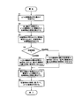
- FIG. 2 is a flowchart for explaining an example of an image composition method by the imaging apparatus of the present invention.
- the exposure control unit 5 of the imaging apparatus 1 controls the left and right imaging systems 2L and 2R to the same exposure, and images the same subject using these two imaging systems 2L and 2R (step S1). It is assumed that the same subject includes two or more subjects having different brightness.
- the left and right image information of the same subject captured in step S ⁇ b> 1 is input to the parallax calculation unit 3 and the determination unit 4.
- the parallax calculation unit 3 calculates the parallax of each subject from the left and right image information input by the imaging systems 2L and 2R (step S2). For this parallax calculation, for example, a block matching method described later can be used.
- the determination unit 4 acquires, for example, pixel values (RGB values) from the left and right image information input from the imaging systems 2L and 2R, and determines the magnitude relationship of the brightness of each subject based on the acquired pixel values.
- the positional relationship (also referred to as arrangement relationship) of each subject is determined (step S3).
- the brightness relationship of each subject is obtained by converting the pixel value (RGB) for each subject into a Y value (YCbCr) and comparing the average value of the brightness of each subject, for example, with a relatively bright subject. A dark subject can be determined.
- each subject is located on the left and right.
- step S4 when it is determined that a bright subject and a dark subject are arranged on the left and right (in the case of left and right light and dark in the figure), the exposure control unit 5 The exposure of the imaging system is adjusted to a bright subject, and the exposure of the other imaging system is adjusted to a dark subject (step S5).
- the exposure control unit 5 sets the exposure of one imaging system to a bright subject on the background (or The exposure of the other imaging system is adjusted to the dark subject (or bright subject) on the foreground side (step S6). Then, the same subject is imaged by the imaging systems 2L and 2R controlled to different exposures in step S5 or step S6.
- the left and right image information obtained by imaging the same subject is input to the parallax calculation unit 3 and the image synthesis unit 6.
- the parallax calculation unit 3 calculates the parallax of each subject from the left and right image information input by the imaging systems 2L and 2R (step S7). Then, the image synthesis unit 6 synthesizes the left and right image information input by the imaging systems 2L and 2R into one image based on the parallax of each subject calculated by the parallax calculation unit 3 (step S8). In this flow, the imaging systems 2L and 2R are set to the same exposure in step S1, but this calculates the parallax more correctly and sets the optimal exposure for the imaging systems 2L and 2R based on this parallax. Because.
- the parallax used for the image composition process in step S8 is calculated from the left and right images captured with different exposures in each frame.
- imaging performed with the same exposure, and further, imaging performed in order to obtain a composite image based on different exposures determined for each imaging system.
- imaging is performed twice, since imaging with the same exposure is not required after two frames, imaging is performed only once with different exposure for each imaging system.
- the exposure control unit 5 adjusts the exposure of one imaging system to the bright subject.
- the exposure of the other imaging system is controlled in accordance with a dark subject.
- the determination unit 4 acquires the brightness and parallax of each subject from the left and right image information captured with the same exposure, and based on this, the magnitude relationship between the brightness of each subject.
- the arrangement relationship of each subject may be determined, or the brightness of each subject may be obtained using a photometric sensor such as a luminance meter, and distance information to each subject may be obtained by the distance measuring sensor.
- the distance information may be calculated from the parallax of each subject if the imaging system specifications such as the focal length and the pixel pitch of the imaging device (CCD sensor) are known. Based on the brightness and distance information of the subject thus obtained, the magnitude relationship of the brightness of each subject and the arrangement relationship of each subject may be determined.
- the plurality of images used for image composition are the first image that is imaged with the exposure of a bright subject by one imaging system and the second image that is imaged with the exposure of a dark subject by the other imaging system. It consists of images.
- the parallax calculation unit 3 calculates the parallax from the first image and the second image, and the image synthesis unit 6 performs the first image when synthesizing the image based on the parallax calculated by the parallax calculation unit 3.
- one of the second images is used as a reference image
- the pixel value of the reference image is used for an area where the pixel value of the reference image is in a predetermined range, and the area where the pixel value of the reference image is not in the predetermined range
- image synthesis is performed using the pixel values of the region corresponding to the region of the other image.
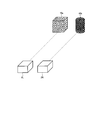
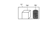
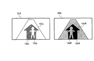
- FIG. 3 is a diagram schematically illustrating an example of imaging a bright subject (bright portion) and a dark subject (dark portion) arranged on the left and right using the two imaging systems 2L and 2R arranged on the left and right. It is.
- 10a indicates a bright subject (hereinafter, bright subject)
- 10b indicates a dark subject (hereinafter, dark subject).
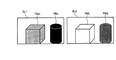
- FIG. 4 shows an image 2L1 that is captured with the exposure of the imaging system 2L adjusted to the bright subject 10a, and an image 2L2 that is also captured with the exposure of the imaging system 2L adjusted to the dark subject 10b.
- the dark subject image 10bL is crushed black as shown in the image 2L1, and the exposure is changed to the dark subject 10b.
- the bright subject image 10aL is overexposed as shown in the image 2L2.
- the exposure of one imaging system 2L is imaged according to the bright subject 10a
- the exposure of the other imaging system 2R is imaged according to the dark subject 10b
- both the captured images are synthesized.
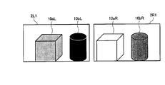
- FIG. 5 shows an image 2L1 obtained by capturing the exposure of the imaging system 2L with the bright subject 10a and an image 2R1 obtained by capturing the exposure of the imaging system 2R with the dark subject 10b.
- the image 2L1 and the image 2R1 correspond to the first image and the second image of the present invention.
- a method for setting the average pixel value of the image to a predetermined value or a method for setting the maximum pixel value or the minimum pixel value of the image to a predetermined value is known. It has been known.
- the captured image of the imaging system 2L does not have a blackout area and the captured image of the imaging system 2R does not have a whiteout area. It is desirable not to make the difference too large.
- the exposure can be set by controlling the aperture, sensitivity, shutter speed, and the like of the imaging apparatus 1. By independently controlling the exposure of the plurality of imaging systems 2L and 2R, it is possible to set an exposure difference suitable for the scene to be imaged.
- the images captured by the imaging systems 2L and 2R with different viewpoints have parallax so that the image 2L1 and the image 2R1 in FIG. 5 have different subject image positions.
- the parallax is larger as the subject is closer to the subject, the parallax is smaller as the subject is farther away, and the parallax of the subject at infinity is zero. Therefore, it is necessary to correct the parallax when combining images.
- the two subjects 10a and 10b are equidistant from the imaging systems 2L and 2R, it is determined that their parallax is equal. Therefore, the parallax of either one of the two subjects 10a and 10b may be calculated.
- the block matching method is a method for evaluating the similarity between images. Select a region from one image, select a region with the highest similarity to that region from the other image, and select from one image. The shift in position between the selected region and the region with the highest similarity selected from the other image is parallax.
- Various evaluation functions are used to evaluate the similarity. For example, there is a method called SAD (Sum of Absolute Difference), which selects a region having the smallest sum of absolute values of differences between pixel values or luminance values of both images as a region having the highest similarity.
- one image is set so that the brightness of the corresponding points of the two images matches in consideration of the exposure difference. It is preferable to perform matching after correcting the luminance value and the pixel value. For example, when the exposure difference ⁇ EV between the image 2L1 and the image 2R1 is 2EV (Exposure Value) and the pixel value of both images is linear with respect to the amount of light incident on the sensor, the pixel value of the image 2L1 is multiplied by 2 EV. By multiplying, the brightness of the corresponding pixels of the two images can be matched.
- 2EV Exposure Value
- FIG. 6 shows an image 2L1 ′ obtained by correcting the pixel values of the image 2L1 so that the brightness of corresponding points in the image 2L1 and the image 2R1 match.
- EV is an exposure setting value given by log 2 ⁇ (square of aperture value) / (shutter speed) ⁇ , and the state when the aperture value is 1.0 and the shutter speed is 1.0 second is 0. .0EV.
- the pixel value of the bright subject image 10aL of the image 2L1 is used as it is for the bright subject 10a
- the dark subject of the image 2R1 is used for the dark subject 10b.
- the threshold value for determining whether or not the exposure is appropriate an appropriate threshold value may be set in consideration of the specifications and characteristics of the imaging system. Note that, when combining images, it is necessary to consider the exposure difference as in the case of calculating parallax by the block matching method.
- the pixel value of the image 2R1 can be matched with the brightness of the corresponding pixel of the image 2L1 by dividing the pixel value of the image 2R1 by 2 to the power of ⁇ EV.
- the parallax calculation by the block matching method will be described in more detail.
- the exposure difference between the images is taken into account, and the brightness of the corresponding points of both images is considered. It is preferable to perform matching after correcting the luminance value or pixel value of one image so that the images match.
- the exposure difference between the two images is large, the following problem occurs.
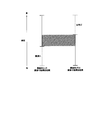
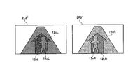
- FIG. 8 shows luminance ranges that can be imaged by the imaging systems 2L and 2R.
- the exposure of the imaging 2L is taken in the bright part, and the exposure of the imaging system 2R is taken in the dark part.
- the dark portion low luminance portion
- the bright portion high luminance portion
- the hatched portion is hatched in both imaging systems 2L and 2R. This is the overlapping luminance range.
- the parallax can be calculated by performing block matching by correcting the exposure difference between the images captured by both imaging systems.
- both imaging systems 2L and 2R are set to the same exposure to image the same subject, and the brightness and parallax of each subject are calculated from the obtained left and right captured images. Based on the calculated brightness and parallax, the exposures of both imaging systems 2L and 2R are appropriately controlled according to the scene. By setting the same exposure in this way, more correct parallax can be obtained.
- interpolation is performed using the parallax values of areas that can be determined to be correctly calculated in the surrounding areas. You may calculate by doing.
- the imaging systems 2L and 2R are once set to the same exposure, the brightness and the parallax are calculated, and then the exposures of the imaging systems 2L and 2R are set appropriately again. Also good.
- the exposure control unit 5 sets the exposure of one imaging system on the background side.
- the exposure of the other imaging system is controlled in accordance with the foreground subject.
- the same subject is imaged by the imaging systems 2L and 2R controlled to different exposures. Accordingly, a plurality of images used for image composition are captured with the first image captured by the one imaging system with the exposure on the background object and the other imaging system with the exposure on the foreground object. And the second image.
- the parallax calculation unit 3 calculates the parallax from the first image and the second image, and the image synthesis unit 6 performs the first image when synthesizing the image based on the parallax calculated by the parallax calculation unit 3.
- the pixel value of the reference image is used for the region where the pixel value of the reference image is in the predetermined range
- the region of the second image is used for the region where the pixel value of the reference image is not in the predetermined range.
- An image is synthesized using the pixel values of the area corresponding to the area.
- the second embodiment will be described below with a specific example.
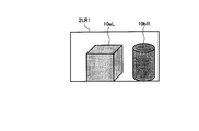
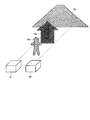
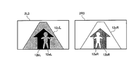
- FIG. 9 is a diagram schematically illustrating an example of imaging a bright subject (bright portion) and a dark subject (dark portion) arranged in front and back using two imaging systems 2L and 2R arranged on the left and right. It is.
- 11a indicates a bright subject
- 11b indicates a dark subject.
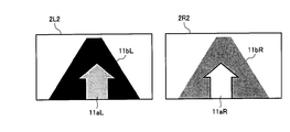
- FIG. 10 shows an image 2L2 that is captured with the exposure of the imaging system 2L matched to the bright subject 11a and an image 2R2 that is captured with the exposure of the imaging system 2R matched to the dark subject 11b.
- FIG. 10 shows an image 2L2 that is captured with the exposure of the imaging system 2L matched to the bright subject 11a and an image 2R2 that is captured with the exposure of the imaging system 2R matched to the dark subject 11b.
- the image 2L2 and the image 2R2 are combined with the image 2L2 matched with the bright subject 11a on the foreground side as a reference, the image 2L2 is captured with an appropriate exposure that does not cause overexposure or blackout.
- the subject 11a may use the pixel value of the bright subject image 11aL of the image 2L2, and the dark subject 11b that is not captured with appropriate exposure in the image 2L2 may use the pixel value of the dark subject image 11bR of the image 2R2.
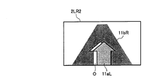
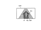
- a composite image 2LR2 captured with appropriate exposure from the bright part to the dark part as shown in FIG. 11 is obtained.
- the left side of the bright subject image 11aL is the occlusion area O, and there is a problem that the image quality deteriorates.
- the dark subject 11b is captured in the image 2L2 of FIG. 10, but the bright subject 11a is captured in the image 2R2, and the dark subject 11b is a shadow of the bright subject 11a.
- an area that is imaged in one imaging system and not imaged in the other imaging system is referred to as occlusion. Since the occlusion region O shown in white in FIG. 11 is crushed black in the image 2L2 in FIG. 10, it is preferable to use the pixel value of the image 2R2 captured with appropriate exposure for the synthesis.
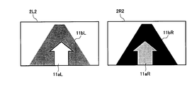
- FIG. 12 shows an image 2L2 obtained by taking the exposure of the imaging system 2L in accordance with the dark subject 11b and an image 2R2 obtained by taking the exposure of the imaging system 2R in accordance with the bright subject 11a.
- FIG. 13 shows a composite image of the image 2L2 and the image 2R2.
- the image 2L2 (corresponding to the first image) obtained by aligning the exposure with the dark subject 11b on the far side is the reference, and the dark subject 11b is imaged with an appropriate exposure.
- the pixel value of the dark subject image 11bL of the image 2L2 being used, and the bright subject 11a that has not been imaged with appropriate exposure in the image 2L2 is the pixel of the bright subject image 11aR of the image 2R2 (corresponding to the second image) Use the value.
- the pixels of the dark subject image 11bL of the image 2L2 are present in the occlusion area O shown in FIG. 11, deterioration due to occlusion does not occur as shown in FIG.
- the area of the bright subject image 11aL is not captured with appropriate exposure and is a whiteout area.
- the area of the bright subject image 11aR is captured with appropriate exposure.
- the bright subject image 11aL of the image 2L2 and the bright subject image 11aR of the image 2R2 are shifted by the amount of parallax.
- the pixel value of the shifted area corresponds to the pixel value of the area of the bright subject image 11aR.
- the pixel values of the bright subject image 11aR area of the image 2R2 are assigned to the bright subject image 11aL area of the image 2L2, and the image synthesis is performed, thereby preventing the occurrence of occlusion.
- the image capturing system of the reference imaging system is imaged according to the subject on the far side, and the exposure of the other imaging system is set to the subject on the near side.
- an exposure setting method in the case where two subjects having different brightness are in front and behind will be described.
- the exposure of the reference imaging system is adjusted to the subject on the far side (background), and the exposure of the other imaging system is set to the near side ( By image-taking in accordance with the subject on the foreground side), it is possible to perform image composition without image quality deterioration.
- the brightness of the subject and the distance information to the subject are required.
- an approximate luminance value can be calculated by calculating using RAW data having a linear value with respect to the amount of light incident on the CCD sensor.
- brightness may be calculated using pixel values (RGB values) of the image.
- RGB values pixel values
- a photometric sensor such as a luminance meter may be used.
- the distance information includes, for example, a distance measuring sensor and a method of calculating using parallax.
- parallax for example, when two imaging systems are arranged so that the optical axes are parallel, the parallax increases with the subject in the foreground, the parallax decreases with the subject in the distance, and becomes infinite.
- the parallax of a certain subject is zero. Therefore, the front-rear relationship of the subject can be determined based on the magnitude of the parallax. If the imaging system specifications such as the focal length and the pixel pitch of the sensor are known, the distance to the subject can be calculated from the parallax value.
- FIG. 14 shows an example of an average value of brightness in each parallax of a certain scene.
- parallax 1 to 6 have a small average brightness value
- parallax 7 and above have a large average brightness value. Therefore, it can be said that the foreground is bright and the background is dark.
- the exposure of the reference imaging system is set to capture the background, for example, an area with a parallax of 6 or less with an appropriate exposure (in this case, an exposure according to a dark subject), and the exposure of the other imaging system is set to the foreground, for example, parallax. What is necessary is just to set so that seven or more areas may be imaged with an appropriate exposure (in this case, an exposure according to a bright subject).
- the foreground and the background may be divided based on the information of the average parallax at each brightness.
- FIG. 15 shows an example of the average parallax at each brightness of a certain scene.
- the exposure of the reference imaging system may be adjusted to the bright part (background), and the exposure of the other imaging system may be adjusted to the dark part (foreground).
- the exposure of the reference imaging system may be adjusted to the minimum parallax area, and the exposure of the other imaging system may be adjusted to the area other than the minimum parallax.
- the reference imaging system may be adjusted to an area other than the maximum parallax, and the other imaging system may be adjusted to the maximum parallax area.
- the exposure control unit 5 brightens the exposure of one imaging system.
- the exposure of the other imaging system is controlled in accordance with the subject and in accordance with the dark subject.
- the same subject is imaged by the imaging systems 2L and 2R controlled to different exposures.
- the plurality of images used for image composition are the first image that is imaged with the exposure of a bright subject by one imaging system and the second image that is imaged with the exposure of a dark subject by the other imaging system. It consists of images.
- the parallax calculation unit 3 calculates the parallax from the first image and the second image, and the image synthesis unit 6 performs the first image when synthesizing the image based on the parallax calculated by the parallax calculation unit 3.
- the second image of the second image from which the exposure is adjusted to the second subject from the front is used as a reference image, and the pixel value of the reference image is used for an area where the pixel value of the reference image is in a predetermined range, For an area where the pixel value of the reference image is not within the predetermined range, image synthesis is performed using the pixel value of the area corresponding to the area of the other image.
- the third embodiment will be described with a specific example.
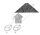
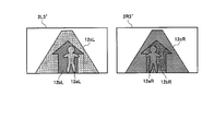
- FIG. 16 is a diagram schematically illustrating an example of imaging a subject arranged in the order of a bright subject, a dark subject, and a bright subject from the front side using the two imaging systems 2L and 2R arranged on the left and right. It is.
- 12a indicates a bright subject
- 12b indicates a dark subject
- 12c indicates a bright subject.
- FIG. 17 shows an image 2L3 captured with the exposure of the imaging system 2L adjusted to the bright subjects 12a and 12c, and an image 2R3 imaged with the exposure of the imaging system 2R adjusted to the dark subject 12b.
- the dark subject image 12bL is blacked out
- the bright subject image 12aR and the bright subject image 12cR are out of focus.
- the bright subjects 12a and 12c may use the pixel values of the bright subject images 12aL and 12cL of the image 2L3
- the dark subject 12b may use the pixel values of the image 2R3 and the dark subject image 12bR.
- the image 2L3 ′ in FIG. 18 shows the areas (12aL, 12cL) captured with appropriate exposure in the image 2L3 in FIG. 17 in light gray, and the blacked areas (12bL) in diagonal lines. It is.
- the image 2R3 ′ in FIG. 18 shows the area (12bR) captured with appropriate exposure in the image 2R3 in FIG. 17 in dark gray, and the overexposed areas (12aR, 12cR) in diagonal lines. It is.
- a part of the dark subject 12b becomes a shadow of the bright subject 12a
- a part of the bright subject 12c becomes a shadow of the dark subject 12b.
- the area 12bL of the image 2L3 is blacked out, it is desirable to use the pixel value of the area 12bR of the image 2R3.
- a part of the area 12bR of the image 2R3 has a whiteout area 12aR, and the corresponding There are no pixels. Therefore, when the image 2L3 and the image 2R3 in FIG. 17 are combined, an occlusion area O1 (hatched area) as shown in FIG. 19 is generated.
- the area of the dark subject image 12bL is not captured with an appropriate exposure and is a blackened area.
- the area of the dark subject image 12bR is captured with appropriate exposure.
- the dark subject image 12bL of the image 2L2 and the dark subject image 12bR of the image 2R2 are shifted by the respective parallaxes.
- this view in the image 2R3 The pixel value of the area shifted by the difference corresponds to the pixel value of the area of the dark subject image 12bR.
- the pixel values of the dark subject image 12bR of the image 2R3 are assigned to the dark subject image 12bL region of the image 2L3, and image synthesis is performed, but part of the dark subject image 12bR region of the image 2R3 is performed.
- FIG. 20 shows an image 2L3 (corresponding to the second image) captured with the exposure of the imaging system 2L adjusted to the dark subject 12b and the exposure of the imaging system 2R adjusted to the bright subjects 12a and 12c.
- An image 2R3 (corresponding to the first image) is shown.
- the bright subject images 12aL and 12cL are whiteout
- the dark subject image 12bR is blacked out.
- the dark subject 12b may use the pixel values of the dark subject image 12bL of the image 2L3, and the bright subjects 12a and 12c may use the pixel values of the bright subject images 12aR and 12cR of the image 2R3. .
- the image 2L3 ′ in FIG. 21 shows the area (12bL) captured with appropriate exposure in the image 2L3 in FIG. 20 in dark gray, and the areas that are overexposed (12aL, 12cL) in diagonal lines. It is.
- the image 2R3 ′ in FIG. 21 shows the regions (12aR, 12cR) captured with appropriate exposure in the image 2R3 in FIG. 20 in light gray, and the blacked regions (12bR) in diagonal lines. It is.
- a part of the dark subject 12b becomes a shadow of the bright subject 12a
- a part of the bright subject 12c becomes a shadow of the dark subject 12b.
- the regions 12aL and 12cL of the image 2L3 are whiteout, it is desirable to use the pixel values of the regions 12aR and 12cR of the image 2R3.
- a blackened region 12bR is included in a part of the region 12cR of the image 2R3. Yes, there is no corresponding pixel. Therefore, when the image 2L3 and the image 2R3 in FIG. 20 are combined, an occlusion region O2 (shaded region) as shown in FIG. 22 is generated.
- the areas of the bright subject images 12aL and 12cL are not captured with appropriate exposure, and are whiteout areas.
- the areas of the bright subject images 12aR and 12cR are captured with appropriate exposure.
- the parallax of each subject is calculated between the images 2L3 and 2R3.
- the pixel value of the region shifted by this amount of parallax corresponds to the pixel value of the region of the bright subject images 12aR and 12cR.
- the pixel values of the bright subject images 12aR and 12cR of the image 2R3 are assigned to the bright subject images 12aL and 12cL of the image 2L3, and image synthesis is performed.
- the bright subject image 12cR of the image 2R3 A part of the region includes a blackened region 12bR, and there is no corresponding pixel. Therefore, occlusion occurs when the images are combined (FIG. 22).
- the exposure of the reference imaging system 2L is adjusted to the dark subject 12b, and the exposure of the imaging system 2R is adjusted to the bright subject.
- the image picked up in accordance with the portions 12a and 12c (example in FIG. 22) has a small occlusion area and can suppress image quality deterioration.
- the influence of the occlusion area can be reduced by using the image 2L3 of the image 2L3 and the image 2R3, in which the exposure is adjusted to the second dark subject 12b from the front as the reference image.
- the exposure of the reference imaging system 2L is adjusted to the second bright subject from the near side, It can be said that the area where the image quality deteriorates due to occlusion can be suppressed to a smaller extent when the exposure of the imaging system 2R is imaged in accordance with a dark subject.
- the reference imaging is possible even when the bright subject, the dark subject, and the bright subject are arranged in this order from the near side, or the dark subject, the bright subject, and the dark subject are arranged in this order from the near side.
- LSI Large Scale Integration
- each functional block of the imaging apparatus may be individually chipped, or a part or all of them may be integrated into a chip.
- the method of the integrated circuit is not limited to LSI, and may be realized by a dedicated circuit or a general-purpose processor.
- processing such as parallax calculation, determination, exposure control, and image composition can be realized by hardware processing such as FPGA (Field Programmable Gate Array) or ASIC (Application Specific Integrated Circuit), or software processing by a microcomputer or the like. it can.
Landscapes
- Engineering & Computer Science (AREA)
- Multimedia (AREA)
- Signal Processing (AREA)
- Studio Devices (AREA)
- Exposure Control For Cameras (AREA)
- Cameras In General (AREA)
Abstract
L'invention concerne un dispositif analyseur d'image, selon lequel une image composite de haute résolution avec une exposition appropriée peut être obtenue, tout en élargissant la plage dynamique de celle-ci. Le dispositif analyseur d'image (1) comprend : une pluralité de systèmes analyseurs d'images (2) ; une unité de calcul de parallaxe (3) pour calculer la parallaxe d'une pluralité d'images analysées par la pluralité de systèmes analyseurs d'images (2) ; une unité d'évaluation (4) pour évaluer la corrélation de grandeur et la corrélation de position entre la luminosité des sujets dans la pluralité d'images ; une unité de commande d'exposition (5) qui est en mesure de commander la pluralité des systèmes analyseurs d'images (2) avec des expositions différentes, en fonction du résultat de l'évaluation par l'unité d'évaluation (4) ; et une unité de composition d'image (6) pour composer la pluralité d'images, en fonction de la parallaxe calculée par l'unité de calcul de parallaxe (3) et l'exposition définie par l'unité de commande d'exposition (5).
Priority Applications (1)
| Application Number | Priority Date | Filing Date | Title |
|---|---|---|---|
| US13/991,971 US20130258139A1 (en) | 2010-12-07 | 2011-11-14 | Imaging apparatus |
Applications Claiming Priority (2)
| Application Number | Priority Date | Filing Date | Title |
|---|---|---|---|
| JP2010272130A JP5411842B2 (ja) | 2010-12-07 | 2010-12-07 | 撮像装置 |
| JP2010-272130 | 2010-12-07 |
Publications (1)
| Publication Number | Publication Date |
|---|---|
| WO2012077464A1 true WO2012077464A1 (fr) | 2012-06-14 |
Family
ID=46206962
Family Applications (1)
| Application Number | Title | Priority Date | Filing Date |
|---|---|---|---|
| PCT/JP2011/076142 WO2012077464A1 (fr) | 2010-12-07 | 2011-11-14 | Dispositif analyseur d'image |
Country Status (3)
| Country | Link |
|---|---|
| US (1) | US20130258139A1 (fr) |
| JP (1) | JP5411842B2 (fr) |
| WO (1) | WO2012077464A1 (fr) |
Families Citing this family (16)
| Publication number | Priority date | Publication date | Assignee | Title |
|---|---|---|---|---|
| JP5968107B2 (ja) * | 2011-09-01 | 2016-08-10 | キヤノン株式会社 | 画像処理方法、画像処理装置およびプログラム |
| JP2013258577A (ja) * | 2012-06-13 | 2013-12-26 | Canon Inc | 撮像装置、撮像方法及びプログラム、画像符号化装置、画像符号化方法及びプログラム |
| EP2677734A3 (fr) * | 2012-06-18 | 2016-01-13 | Sony Mobile Communications AB | Système d'imagerie à caméra de réseau et procédé |
| KR101207343B1 (ko) * | 2012-08-30 | 2012-12-04 | 재단법인대구경북과학기술원 | 영상 밝기 조절 방법 및 그 장치와, 스테레오 카메라 |
| KR101711370B1 (ko) | 2012-10-29 | 2017-03-02 | 삼성전자주식회사 | 영상 처리 방법 및 장치 |
| WO2014077047A1 (fr) * | 2012-11-15 | 2014-05-22 | ソニー株式会社 | Dispositif de traitement d'image, méthode de traitement d'image, et programme |
| JP6397281B2 (ja) | 2013-10-23 | 2018-09-26 | キヤノン株式会社 | 撮像装置、その制御方法およびプログラム |
| US10306165B2 (en) | 2013-12-06 | 2019-05-28 | Huawei Device Co., Ltd. | Image generating method and dual-lens device |
| EP3138468A4 (fr) * | 2014-12-15 | 2018-01-17 | Olympus Corporation | Système de capture d'image |
| JP6493787B2 (ja) * | 2015-01-19 | 2019-04-03 | 株式会社リコー | 撮像装置、撮像方法及び撮像動作制御プログラム |
| EP3067011B1 (fr) * | 2015-03-09 | 2022-05-25 | Renfert GmbH | Dispositif de formation d'images dentaires |
| JP2017069926A (ja) * | 2015-10-02 | 2017-04-06 | ソニー株式会社 | 画像処理装置、および画像処理方法、並びにプログラム |
| JP2018169517A (ja) * | 2017-03-30 | 2018-11-01 | ソニーセミコンダクタソリューションズ株式会社 | 撮像装置、撮像モジュールおよび撮像装置の制御方法 |
| EP3462743A1 (fr) * | 2017-09-27 | 2019-04-03 | Thomson Licensing | Dispositif et procédé d'expansion de plage dynamique dans une scène de réalité virtuelle |
| JP6959277B2 (ja) * | 2019-02-27 | 2021-11-02 | ファナック株式会社 | 3次元撮影装置および3次元撮影条件調整方法 |
| JP2020167517A (ja) * | 2019-03-29 | 2020-10-08 | ソニー株式会社 | 画像処理装置と画像処理方法とプログラムおよび撮像装置 |
Citations (3)
| Publication number | Priority date | Publication date | Assignee | Title |
|---|---|---|---|---|
| JP2003018617A (ja) * | 2001-07-03 | 2003-01-17 | Olympus Optical Co Ltd | 撮像装置 |
| JP2004096488A (ja) * | 2002-08-30 | 2004-03-25 | Fujitsu Ltd | 物体検知装置、物体検知方法および物体検知プログラム |
| JP2008092005A (ja) * | 2006-09-29 | 2008-04-17 | Casio Comput Co Ltd | 電子カメラ、撮像制御プログラム及び撮像制御方法 |
Family Cites Families (2)
| Publication number | Priority date | Publication date | Assignee | Title |
|---|---|---|---|---|
| US7298402B2 (en) * | 2000-10-26 | 2007-11-20 | Olympus Corporation | Image-pickup apparatus with expanded dynamic range capabilities |
| JP5450200B2 (ja) * | 2009-07-17 | 2014-03-26 | 富士フイルム株式会社 | 撮像装置、方法およびプログラム |
-
2010
- 2010-12-07 JP JP2010272130A patent/JP5411842B2/ja not_active Expired - Fee Related
-
2011
- 2011-11-14 US US13/991,971 patent/US20130258139A1/en not_active Abandoned
- 2011-11-14 WO PCT/JP2011/076142 patent/WO2012077464A1/fr active Application Filing
Patent Citations (3)
| Publication number | Priority date | Publication date | Assignee | Title |
|---|---|---|---|---|
| JP2003018617A (ja) * | 2001-07-03 | 2003-01-17 | Olympus Optical Co Ltd | 撮像装置 |
| JP2004096488A (ja) * | 2002-08-30 | 2004-03-25 | Fujitsu Ltd | 物体検知装置、物体検知方法および物体検知プログラム |
| JP2008092005A (ja) * | 2006-09-29 | 2008-04-17 | Casio Comput Co Ltd | 電子カメラ、撮像制御プログラム及び撮像制御方法 |
Also Published As
| Publication number | Publication date |
|---|---|
| JP2012124622A (ja) | 2012-06-28 |
| US20130258139A1 (en) | 2013-10-03 |
| JP5411842B2 (ja) | 2014-02-12 |
Similar Documents
| Publication | Publication Date | Title |
|---|---|---|
| JP5411842B2 (ja) | 撮像装置 | |
| US8218036B2 (en) | Image sensing apparatus and control method therefor | |
| CN107846556B (zh) | 成像方法、装置、移动终端和存储介质 | |
| CN108886581B (zh) | 图像处理装置、摄像装置及其控制方法 | |
| JP6489932B2 (ja) | 画像処理装置、撮像装置、画像処理方法およびプログラム | |
| JP6110574B2 (ja) | ハイダイナミックレンジ画像化方法及びカメラ | |
| JP5860663B2 (ja) | ステレオ撮像装置 | |
| US9892497B2 (en) | Image processing apparatus, imaging apparatus, and image processing method | |
| JP5857444B2 (ja) | 撮像装置 | |
| JP2017118296A (ja) | 撮像装置、画像処理装置、画像処理方法、画像処理プログラム、および、記憶媒体 | |
| JP2015144475A (ja) | 撮像装置、撮像装置の制御方法、プログラム及び記憶媒体 | |
| JP5882702B2 (ja) | 撮像装置 | |
| JP5713643B2 (ja) | 撮像装置、撮像装置の制御方法、プログラム及び記憶媒体 | |
| JP5569617B2 (ja) | 画像処理装置、及び、プログラム | |
| JP2010026018A (ja) | カメラ装置、その撮影方法と撮影制御プログラム | |
| JP4857556B2 (ja) | 車載用カメラ映像提示装置 | |
| JP5245648B2 (ja) | 画像処理装置、及び、プログラム | |
| US8421907B2 (en) | Imager that photographs an image using a rolling shutter | |
| JP6746738B2 (ja) | 画像処理装置、撮像装置、画像処理方法およびプログラム | |
| JP6519625B2 (ja) | 撮像装置 | |
| JP2011135379A (ja) | 撮像装置、撮像方法及びプログラム | |
| JP6725105B2 (ja) | 撮像装置及び画像処理方法 | |
| US7986348B2 (en) | Photometric device | |
| JP6570230B2 (ja) | 撮像装置および撮像方法 | |
| JP6222335B2 (ja) | 撮像装置 |
Legal Events
| Date | Code | Title | Description |
|---|---|---|---|
| 121 | Ep: the epo has been informed by wipo that ep was designated in this application |
Ref document number: 11846730 Country of ref document: EP Kind code of ref document: A1 |
|
| DPE1 | Request for preliminary examination filed after expiration of 19th month from priority date (pct application filed from 20040101) | ||
| WWE | Wipo information: entry into national phase |
Ref document number: 13991971 Country of ref document: US |
|
| NENP | Non-entry into the national phase |
Ref country code: DE |
|
| 122 | Ep: pct application non-entry in european phase |
Ref document number: 11846730 Country of ref document: EP Kind code of ref document: A1 |