WO2012077464A1 - Image pickup device - Google Patents
Image pickup device Download PDFInfo
- Publication number
- WO2012077464A1 WO2012077464A1 PCT/JP2011/076142 JP2011076142W WO2012077464A1 WO 2012077464 A1 WO2012077464 A1 WO 2012077464A1 JP 2011076142 W JP2011076142 W JP 2011076142W WO 2012077464 A1 WO2012077464 A1 WO 2012077464A1
- Authority
- WO
- WIPO (PCT)
- Prior art keywords
- image
- subject
- exposure
- parallax
- imaging
- Prior art date
Links
Images


Classifications
-
- H—ELECTRICITY
- H04—ELECTRIC COMMUNICATION TECHNIQUE
- H04N—PICTORIAL COMMUNICATION, e.g. TELEVISION
- H04N5/00—Details of television systems
- H04N5/222—Studio circuitry; Studio devices; Studio equipment
- H04N5/262—Studio circuits, e.g. for mixing, switching-over, change of character of image, other special effects ; Cameras specially adapted for the electronic generation of special effects
- H04N5/265—Mixing
-
- H—ELECTRICITY
- H04—ELECTRIC COMMUNICATION TECHNIQUE
- H04N—PICTORIAL COMMUNICATION, e.g. TELEVISION
- H04N13/00—Stereoscopic video systems; Multi-view video systems; Details thereof
- H04N13/10—Processing, recording or transmission of stereoscopic or multi-view image signals
- H04N13/106—Processing image signals
- H04N13/156—Mixing image signals
-
- H—ELECTRICITY
- H04—ELECTRIC COMMUNICATION TECHNIQUE
- H04N—PICTORIAL COMMUNICATION, e.g. TELEVISION
- H04N13/00—Stereoscopic video systems; Multi-view video systems; Details thereof
- H04N13/20—Image signal generators
- H04N13/204—Image signal generators using stereoscopic image cameras
- H04N13/239—Image signal generators using stereoscopic image cameras using two 2D image sensors having a relative position equal to or related to the interocular distance
Definitions
- the present invention relates to an imaging apparatus including a plurality of imaging systems that image the same subject from different viewpoints.
- the dynamic range in a camera is the ratio of maximum and minimum brightness that can be identified.
- the dynamic range of an image sensor such as a CCD or CMOS mounted on a general digital camera currently on the market is about 2000: 1 even if it has a high dynamic range.
- the ratio of the maximum luminance to the minimum luminance of the subject is 100000: 1 or more depending on the scene.
- Patent Document 1 proposes a technique for expanding the dynamic range by combining a plurality of images with different exposures. In this method, since imaging is performed a plurality of times with the same imaging system, there is a problem that when a subject is a moving object, a plurality of images used for synthesis are shifted, and synthesis is difficult.
- Patent Document 2 proposes a multi-lens camera that synthesizes images obtained by simultaneously imaging subjects with a plurality of imaging systems.
- This multi-lens camera includes a CCD that receives and shoots a light beam of a subject image, and a plurality of photographing optical systems that guide the subject image to the CCD.
- Each of the plurality of photographing optical systems has different visible light transmittance.
- An optical filter is attached, and a plurality of subject images from a plurality of photographing optical systems are photographed simultaneously.
- each imaging system is provided with a filter having a different visible light transmittance, so that each imaging system is set to a different exposure.
- the visible light transmittance of the filter is fixed, each imaging is performed for a scene to be imaged. System exposure differences are not always appropriate.
- parallax occurs between the plurality of images. For example, the parallax increases as the subject is closer to the subject, and the parallax decreases as the subject is farther away.
- this parallax is not taken into account, if a plurality of images having different viewpoints are simply combined, there is a possibility that the subject images may be misaligned and the combination may not be successful. .
- the present invention has been made in view of the above circumstances, and an object of the present invention is to provide an imaging apparatus capable of obtaining a high-quality composite image with appropriate exposure while expanding the dynamic range.
- the first technical means of the present invention includes a plurality of imaging systems, a parallax calculation unit that calculates parallaxes of a plurality of images captured by the plurality of imaging systems, and the plurality of images.
- a determination unit that determines the magnitude relationship and positional relationship of the brightness of the subject inside
- an exposure control unit that can control a plurality of imaging systems to different exposures based on the determination result of the determination unit, and the parallax and the exposure
- an image composition unit that composes the plurality of images based on the image.
- the exposure control unit determines the exposure of one imaging system. It is characterized by controlling the exposure of the other imaging system so that it matches a bright subject and a dark subject.
- the plurality of images include a first image picked up with exposure of a bright subject by the one imaging system and a dark subject by the other imaging system.
- the parallax calculation unit calculates the parallax from the first image and the second image
- the image composition unit calculates the parallax.
- the exposure control unit when the determination unit determines that a bright subject and a dark subject are arranged before and after, includes the plurality of image composition units.
- the exposure of the imaging system that captures the reference image serving as a reference when combining the images is adjusted to the foreground subject, and the exposure of the other imaging system is controlled to match the foreground subject.
- the plurality of images are: a first image captured by an imaging system that captures the reference image and a subject on the background side being exposed. And the second image captured by the other imaging system with the foreground subject adjusted to the exposure, and the parallax calculation unit calculates the parallax from the first image and the second image.
- the image composition unit composes an image based on the parallax calculated by the parallax calculation unit, the pixel of the first image is applied to an area where the pixel value of the first image is in a predetermined range. And, for an area where the pixel value of the first image is not within a predetermined range, image synthesis is performed using the pixel value of the area corresponding to the area of the second image. .
- the exposure control unit Adjusts the exposure of the imaging system that captures a reference image when combining the plurality of images to a subject having a brightness different from that of the subject in front, and controls the exposure of the other imaging system to match the subject in front It is characterized by that.
- the plurality of images are picked up by an image pickup system for picking up the reference image, with a subject having a brightness different from that of a subject in front of the subject, with exposure adjusted.
- the parallax is calculated, and the image synthesizing unit, when synthesizing the image based on the parallax calculated by the parallax calculating unit, for the region where the pixel value of the first image is in a predetermined range, The pixel value of the image of the first image is used, and for the region where the pixel value of the first image is not within a predetermined range, the image value is synthesized using the pixel value of the region corresponding to the region of the second image. It is characterized by.
- the eighth technical means is the technical means according to any one of the second, fourth and sixth technical means, wherein the exposure control unit controls the plurality of imaging systems to have the same exposure, and the parallax calculation unit comprises the exposure.
- the parallax of a plurality of images captured by the plurality of imaging systems controlled to the same exposure by the control unit is calculated, and the determination unit determines the magnitude relationship of the brightness of each subject based on the pixel values of the plurality of pixels And determining the positional relationship of each subject based on the parallax of each subject calculated by the parallax calculation unit.
- the exposure for each imaging system is appropriately controlled according to the subject, and the obtained images are synthesized based on parallax. It is possible to obtain a high-quality composite image in which exposure is matched from the dark part to the bright part while expanding the dynamic range.
- FIG. 1 is a block diagram illustrating a configuration example of an imaging apparatus according to an embodiment of the present invention.
- reference numeral 1 denotes an imaging device.
- the imaging device 1 includes a plurality of imaging systems 2 that image the same subject from different viewpoints.
- two imaging systems 2 are arranged on the left and right, and are constituted by a CCD (Charge Coupled Device) which is an example of a solid-state imaging device and a photographing optical system for guiding a subject image to the CCD.
- the solid-state imaging device is not limited to a CCD but may be a CMOS, but a CCD will be described below as a representative example.
- the imaging apparatus 1 includes a parallax calculation unit 3 that calculates parallaxes of a plurality of images captured by a plurality of imaging systems 2, and a determination unit that determines a magnitude relationship and a positional relationship between the brightness of subjects in the plurality of images. 4, based on the exposure control unit 5 that can control the plurality of imaging systems 2 to different exposures based on the determination result of the determination unit 4, the parallax calculated by the parallax calculation unit 3, and the exposure set by the exposure control unit 5 And an image composition unit 6 that composes a plurality of images.
- the determination unit 4 determines the magnitude relationship of the brightness of each subject and the positional relationship of each subject with respect to two or more subjects included in the same subject.
- the exposure control unit 5 controls the plurality of imaging systems 2 to different exposures based on the determination result of the determination unit 4.
- the parallax calculation unit 3 calculates the parallax from a plurality of images captured by the plurality of imaging systems 2 controlled to different exposures by the exposure control unit 5.
- the image synthesis unit 6 synthesizes a plurality of images based on the parallax calculated by the parallax calculation unit 3.
- FIG. 2 is a flowchart for explaining an example of an image composition method by the imaging apparatus of the present invention.
- the exposure control unit 5 of the imaging apparatus 1 controls the left and right imaging systems 2L and 2R to the same exposure, and images the same subject using these two imaging systems 2L and 2R (step S1). It is assumed that the same subject includes two or more subjects having different brightness.
- the left and right image information of the same subject captured in step S ⁇ b> 1 is input to the parallax calculation unit 3 and the determination unit 4.
- the parallax calculation unit 3 calculates the parallax of each subject from the left and right image information input by the imaging systems 2L and 2R (step S2). For this parallax calculation, for example, a block matching method described later can be used.
- the determination unit 4 acquires, for example, pixel values (RGB values) from the left and right image information input from the imaging systems 2L and 2R, and determines the magnitude relationship of the brightness of each subject based on the acquired pixel values.
- the positional relationship (also referred to as arrangement relationship) of each subject is determined (step S3).
- the brightness relationship of each subject is obtained by converting the pixel value (RGB) for each subject into a Y value (YCbCr) and comparing the average value of the brightness of each subject, for example, with a relatively bright subject. A dark subject can be determined.
- each subject is located on the left and right.
- step S4 when it is determined that a bright subject and a dark subject are arranged on the left and right (in the case of left and right light and dark in the figure), the exposure control unit 5 The exposure of the imaging system is adjusted to a bright subject, and the exposure of the other imaging system is adjusted to a dark subject (step S5).
- the exposure control unit 5 sets the exposure of one imaging system to a bright subject on the background (or The exposure of the other imaging system is adjusted to the dark subject (or bright subject) on the foreground side (step S6). Then, the same subject is imaged by the imaging systems 2L and 2R controlled to different exposures in step S5 or step S6.
- the left and right image information obtained by imaging the same subject is input to the parallax calculation unit 3 and the image synthesis unit 6.
- the parallax calculation unit 3 calculates the parallax of each subject from the left and right image information input by the imaging systems 2L and 2R (step S7). Then, the image synthesis unit 6 synthesizes the left and right image information input by the imaging systems 2L and 2R into one image based on the parallax of each subject calculated by the parallax calculation unit 3 (step S8). In this flow, the imaging systems 2L and 2R are set to the same exposure in step S1, but this calculates the parallax more correctly and sets the optimal exposure for the imaging systems 2L and 2R based on this parallax. Because.
- the parallax used for the image composition process in step S8 is calculated from the left and right images captured with different exposures in each frame.
- imaging performed with the same exposure, and further, imaging performed in order to obtain a composite image based on different exposures determined for each imaging system.
- imaging is performed twice, since imaging with the same exposure is not required after two frames, imaging is performed only once with different exposure for each imaging system.
- the exposure control unit 5 adjusts the exposure of one imaging system to the bright subject.
- the exposure of the other imaging system is controlled in accordance with a dark subject.
- the determination unit 4 acquires the brightness and parallax of each subject from the left and right image information captured with the same exposure, and based on this, the magnitude relationship between the brightness of each subject.
- the arrangement relationship of each subject may be determined, or the brightness of each subject may be obtained using a photometric sensor such as a luminance meter, and distance information to each subject may be obtained by the distance measuring sensor.
- the distance information may be calculated from the parallax of each subject if the imaging system specifications such as the focal length and the pixel pitch of the imaging device (CCD sensor) are known. Based on the brightness and distance information of the subject thus obtained, the magnitude relationship of the brightness of each subject and the arrangement relationship of each subject may be determined.
- the plurality of images used for image composition are the first image that is imaged with the exposure of a bright subject by one imaging system and the second image that is imaged with the exposure of a dark subject by the other imaging system. It consists of images.
- the parallax calculation unit 3 calculates the parallax from the first image and the second image, and the image synthesis unit 6 performs the first image when synthesizing the image based on the parallax calculated by the parallax calculation unit 3.
- one of the second images is used as a reference image
- the pixel value of the reference image is used for an area where the pixel value of the reference image is in a predetermined range, and the area where the pixel value of the reference image is not in the predetermined range
- image synthesis is performed using the pixel values of the region corresponding to the region of the other image.
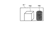
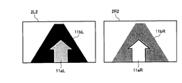
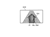
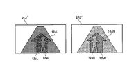
- FIG. 3 is a diagram schematically illustrating an example of imaging a bright subject (bright portion) and a dark subject (dark portion) arranged on the left and right using the two imaging systems 2L and 2R arranged on the left and right. It is.
- 10a indicates a bright subject (hereinafter, bright subject)
- 10b indicates a dark subject (hereinafter, dark subject).
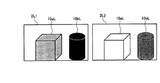
- FIG. 4 shows an image 2L1 that is captured with the exposure of the imaging system 2L adjusted to the bright subject 10a, and an image 2L2 that is also captured with the exposure of the imaging system 2L adjusted to the dark subject 10b.
- the dark subject image 10bL is crushed black as shown in the image 2L1, and the exposure is changed to the dark subject 10b.
- the bright subject image 10aL is overexposed as shown in the image 2L2.
- the exposure of one imaging system 2L is imaged according to the bright subject 10a
- the exposure of the other imaging system 2R is imaged according to the dark subject 10b
- both the captured images are synthesized.
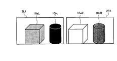
- FIG. 5 shows an image 2L1 obtained by capturing the exposure of the imaging system 2L with the bright subject 10a and an image 2R1 obtained by capturing the exposure of the imaging system 2R with the dark subject 10b.
- the image 2L1 and the image 2R1 correspond to the first image and the second image of the present invention.
- a method for setting the average pixel value of the image to a predetermined value or a method for setting the maximum pixel value or the minimum pixel value of the image to a predetermined value is known. It has been known.
- the captured image of the imaging system 2L does not have a blackout area and the captured image of the imaging system 2R does not have a whiteout area. It is desirable not to make the difference too large.
- the exposure can be set by controlling the aperture, sensitivity, shutter speed, and the like of the imaging apparatus 1. By independently controlling the exposure of the plurality of imaging systems 2L and 2R, it is possible to set an exposure difference suitable for the scene to be imaged.
- the images captured by the imaging systems 2L and 2R with different viewpoints have parallax so that the image 2L1 and the image 2R1 in FIG. 5 have different subject image positions.
- the parallax is larger as the subject is closer to the subject, the parallax is smaller as the subject is farther away, and the parallax of the subject at infinity is zero. Therefore, it is necessary to correct the parallax when combining images.
- the two subjects 10a and 10b are equidistant from the imaging systems 2L and 2R, it is determined that their parallax is equal. Therefore, the parallax of either one of the two subjects 10a and 10b may be calculated.
- the block matching method is a method for evaluating the similarity between images. Select a region from one image, select a region with the highest similarity to that region from the other image, and select from one image. The shift in position between the selected region and the region with the highest similarity selected from the other image is parallax.
- Various evaluation functions are used to evaluate the similarity. For example, there is a method called SAD (Sum of Absolute Difference), which selects a region having the smallest sum of absolute values of differences between pixel values or luminance values of both images as a region having the highest similarity.
- one image is set so that the brightness of the corresponding points of the two images matches in consideration of the exposure difference. It is preferable to perform matching after correcting the luminance value and the pixel value. For example, when the exposure difference ⁇ EV between the image 2L1 and the image 2R1 is 2EV (Exposure Value) and the pixel value of both images is linear with respect to the amount of light incident on the sensor, the pixel value of the image 2L1 is multiplied by 2 EV. By multiplying, the brightness of the corresponding pixels of the two images can be matched.
- 2EV Exposure Value
- FIG. 6 shows an image 2L1 ′ obtained by correcting the pixel values of the image 2L1 so that the brightness of corresponding points in the image 2L1 and the image 2R1 match.
- EV is an exposure setting value given by log 2 ⁇ (square of aperture value) / (shutter speed) ⁇ , and the state when the aperture value is 1.0 and the shutter speed is 1.0 second is 0. .0EV.
- the pixel value of the bright subject image 10aL of the image 2L1 is used as it is for the bright subject 10a
- the dark subject of the image 2R1 is used for the dark subject 10b.
- the threshold value for determining whether or not the exposure is appropriate an appropriate threshold value may be set in consideration of the specifications and characteristics of the imaging system. Note that, when combining images, it is necessary to consider the exposure difference as in the case of calculating parallax by the block matching method.
- the pixel value of the image 2R1 can be matched with the brightness of the corresponding pixel of the image 2L1 by dividing the pixel value of the image 2R1 by 2 to the power of ⁇ EV.
- the parallax calculation by the block matching method will be described in more detail.
- the exposure difference between the images is taken into account, and the brightness of the corresponding points of both images is considered. It is preferable to perform matching after correcting the luminance value or pixel value of one image so that the images match.
- the exposure difference between the two images is large, the following problem occurs.
- FIG. 8 shows luminance ranges that can be imaged by the imaging systems 2L and 2R.
- the exposure of the imaging 2L is taken in the bright part, and the exposure of the imaging system 2R is taken in the dark part.
- the dark portion low luminance portion
- the bright portion high luminance portion
- the hatched portion is hatched in both imaging systems 2L and 2R. This is the overlapping luminance range.
- the parallax can be calculated by performing block matching by correcting the exposure difference between the images captured by both imaging systems.
- both imaging systems 2L and 2R are set to the same exposure to image the same subject, and the brightness and parallax of each subject are calculated from the obtained left and right captured images. Based on the calculated brightness and parallax, the exposures of both imaging systems 2L and 2R are appropriately controlled according to the scene. By setting the same exposure in this way, more correct parallax can be obtained.
- interpolation is performed using the parallax values of areas that can be determined to be correctly calculated in the surrounding areas. You may calculate by doing.
- the imaging systems 2L and 2R are once set to the same exposure, the brightness and the parallax are calculated, and then the exposures of the imaging systems 2L and 2R are set appropriately again. Also good.
- the exposure control unit 5 sets the exposure of one imaging system on the background side.
- the exposure of the other imaging system is controlled in accordance with the foreground subject.
- the same subject is imaged by the imaging systems 2L and 2R controlled to different exposures. Accordingly, a plurality of images used for image composition are captured with the first image captured by the one imaging system with the exposure on the background object and the other imaging system with the exposure on the foreground object. And the second image.
- the parallax calculation unit 3 calculates the parallax from the first image and the second image, and the image synthesis unit 6 performs the first image when synthesizing the image based on the parallax calculated by the parallax calculation unit 3.
- the pixel value of the reference image is used for the region where the pixel value of the reference image is in the predetermined range
- the region of the second image is used for the region where the pixel value of the reference image is not in the predetermined range.
- An image is synthesized using the pixel values of the area corresponding to the area.
- the second embodiment will be described below with a specific example.
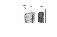
- FIG. 9 is a diagram schematically illustrating an example of imaging a bright subject (bright portion) and a dark subject (dark portion) arranged in front and back using two imaging systems 2L and 2R arranged on the left and right. It is.
- 11a indicates a bright subject
- 11b indicates a dark subject.
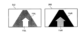
- FIG. 10 shows an image 2L2 that is captured with the exposure of the imaging system 2L matched to the bright subject 11a and an image 2R2 that is captured with the exposure of the imaging system 2R matched to the dark subject 11b.
- FIG. 10 shows an image 2L2 that is captured with the exposure of the imaging system 2L matched to the bright subject 11a and an image 2R2 that is captured with the exposure of the imaging system 2R matched to the dark subject 11b.
- the image 2L2 and the image 2R2 are combined with the image 2L2 matched with the bright subject 11a on the foreground side as a reference, the image 2L2 is captured with an appropriate exposure that does not cause overexposure or blackout.
- the subject 11a may use the pixel value of the bright subject image 11aL of the image 2L2, and the dark subject 11b that is not captured with appropriate exposure in the image 2L2 may use the pixel value of the dark subject image 11bR of the image 2R2.
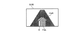
- a composite image 2LR2 captured with appropriate exposure from the bright part to the dark part as shown in FIG. 11 is obtained.
- the left side of the bright subject image 11aL is the occlusion area O, and there is a problem that the image quality deteriorates.
- the dark subject 11b is captured in the image 2L2 of FIG. 10, but the bright subject 11a is captured in the image 2R2, and the dark subject 11b is a shadow of the bright subject 11a.
- an area that is imaged in one imaging system and not imaged in the other imaging system is referred to as occlusion. Since the occlusion region O shown in white in FIG. 11 is crushed black in the image 2L2 in FIG. 10, it is preferable to use the pixel value of the image 2R2 captured with appropriate exposure for the synthesis.
- FIG. 12 shows an image 2L2 obtained by taking the exposure of the imaging system 2L in accordance with the dark subject 11b and an image 2R2 obtained by taking the exposure of the imaging system 2R in accordance with the bright subject 11a.
- FIG. 13 shows a composite image of the image 2L2 and the image 2R2.
- the image 2L2 (corresponding to the first image) obtained by aligning the exposure with the dark subject 11b on the far side is the reference, and the dark subject 11b is imaged with an appropriate exposure.
- the pixel value of the dark subject image 11bL of the image 2L2 being used, and the bright subject 11a that has not been imaged with appropriate exposure in the image 2L2 is the pixel of the bright subject image 11aR of the image 2R2 (corresponding to the second image) Use the value.
- the pixels of the dark subject image 11bL of the image 2L2 are present in the occlusion area O shown in FIG. 11, deterioration due to occlusion does not occur as shown in FIG.
- the area of the bright subject image 11aL is not captured with appropriate exposure and is a whiteout area.
- the area of the bright subject image 11aR is captured with appropriate exposure.
- the bright subject image 11aL of the image 2L2 and the bright subject image 11aR of the image 2R2 are shifted by the amount of parallax.
- the pixel value of the shifted area corresponds to the pixel value of the area of the bright subject image 11aR.
- the pixel values of the bright subject image 11aR area of the image 2R2 are assigned to the bright subject image 11aL area of the image 2L2, and the image synthesis is performed, thereby preventing the occurrence of occlusion.
- the image capturing system of the reference imaging system is imaged according to the subject on the far side, and the exposure of the other imaging system is set to the subject on the near side.
- an exposure setting method in the case where two subjects having different brightness are in front and behind will be described.
- the exposure of the reference imaging system is adjusted to the subject on the far side (background), and the exposure of the other imaging system is set to the near side ( By image-taking in accordance with the subject on the foreground side), it is possible to perform image composition without image quality deterioration.
- the brightness of the subject and the distance information to the subject are required.
- an approximate luminance value can be calculated by calculating using RAW data having a linear value with respect to the amount of light incident on the CCD sensor.
- brightness may be calculated using pixel values (RGB values) of the image.
- RGB values pixel values
- a photometric sensor such as a luminance meter may be used.
- the distance information includes, for example, a distance measuring sensor and a method of calculating using parallax.
- parallax for example, when two imaging systems are arranged so that the optical axes are parallel, the parallax increases with the subject in the foreground, the parallax decreases with the subject in the distance, and becomes infinite.
- the parallax of a certain subject is zero. Therefore, the front-rear relationship of the subject can be determined based on the magnitude of the parallax. If the imaging system specifications such as the focal length and the pixel pitch of the sensor are known, the distance to the subject can be calculated from the parallax value.
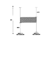
- FIG. 14 shows an example of an average value of brightness in each parallax of a certain scene.
- parallax 1 to 6 have a small average brightness value
- parallax 7 and above have a large average brightness value. Therefore, it can be said that the foreground is bright and the background is dark.
- the exposure of the reference imaging system is set to capture the background, for example, an area with a parallax of 6 or less with an appropriate exposure (in this case, an exposure according to a dark subject), and the exposure of the other imaging system is set to the foreground, for example, parallax. What is necessary is just to set so that seven or more areas may be imaged with an appropriate exposure (in this case, an exposure according to a bright subject).
- the foreground and the background may be divided based on the information of the average parallax at each brightness.
- FIG. 15 shows an example of the average parallax at each brightness of a certain scene.
- the exposure of the reference imaging system may be adjusted to the bright part (background), and the exposure of the other imaging system may be adjusted to the dark part (foreground).
- the exposure of the reference imaging system may be adjusted to the minimum parallax area, and the exposure of the other imaging system may be adjusted to the area other than the minimum parallax.
- the reference imaging system may be adjusted to an area other than the maximum parallax, and the other imaging system may be adjusted to the maximum parallax area.
- the exposure control unit 5 brightens the exposure of one imaging system.
- the exposure of the other imaging system is controlled in accordance with the subject and in accordance with the dark subject.
- the same subject is imaged by the imaging systems 2L and 2R controlled to different exposures.
- the plurality of images used for image composition are the first image that is imaged with the exposure of a bright subject by one imaging system and the second image that is imaged with the exposure of a dark subject by the other imaging system. It consists of images.
- the parallax calculation unit 3 calculates the parallax from the first image and the second image, and the image synthesis unit 6 performs the first image when synthesizing the image based on the parallax calculated by the parallax calculation unit 3.
- the second image of the second image from which the exposure is adjusted to the second subject from the front is used as a reference image, and the pixel value of the reference image is used for an area where the pixel value of the reference image is in a predetermined range, For an area where the pixel value of the reference image is not within the predetermined range, image synthesis is performed using the pixel value of the area corresponding to the area of the other image.
- the third embodiment will be described with a specific example.
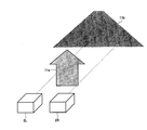
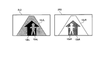
- FIG. 16 is a diagram schematically illustrating an example of imaging a subject arranged in the order of a bright subject, a dark subject, and a bright subject from the front side using the two imaging systems 2L and 2R arranged on the left and right. It is.
- 12a indicates a bright subject
- 12b indicates a dark subject
- 12c indicates a bright subject.
- FIG. 17 shows an image 2L3 captured with the exposure of the imaging system 2L adjusted to the bright subjects 12a and 12c, and an image 2R3 imaged with the exposure of the imaging system 2R adjusted to the dark subject 12b.
- the dark subject image 12bL is blacked out
- the bright subject image 12aR and the bright subject image 12cR are out of focus.
- the bright subjects 12a and 12c may use the pixel values of the bright subject images 12aL and 12cL of the image 2L3
- the dark subject 12b may use the pixel values of the image 2R3 and the dark subject image 12bR.
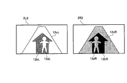
- the image 2L3 ′ in FIG. 18 shows the areas (12aL, 12cL) captured with appropriate exposure in the image 2L3 in FIG. 17 in light gray, and the blacked areas (12bL) in diagonal lines. It is.
- the image 2R3 ′ in FIG. 18 shows the area (12bR) captured with appropriate exposure in the image 2R3 in FIG. 17 in dark gray, and the overexposed areas (12aR, 12cR) in diagonal lines. It is.
- a part of the dark subject 12b becomes a shadow of the bright subject 12a
- a part of the bright subject 12c becomes a shadow of the dark subject 12b.
- the area 12bL of the image 2L3 is blacked out, it is desirable to use the pixel value of the area 12bR of the image 2R3.
- a part of the area 12bR of the image 2R3 has a whiteout area 12aR, and the corresponding There are no pixels. Therefore, when the image 2L3 and the image 2R3 in FIG. 17 are combined, an occlusion area O1 (hatched area) as shown in FIG. 19 is generated.
- the area of the dark subject image 12bL is not captured with an appropriate exposure and is a blackened area.
- the area of the dark subject image 12bR is captured with appropriate exposure.
- the dark subject image 12bL of the image 2L2 and the dark subject image 12bR of the image 2R2 are shifted by the respective parallaxes.
- this view in the image 2R3 The pixel value of the area shifted by the difference corresponds to the pixel value of the area of the dark subject image 12bR.
- the pixel values of the dark subject image 12bR of the image 2R3 are assigned to the dark subject image 12bL region of the image 2L3, and image synthesis is performed, but part of the dark subject image 12bR region of the image 2R3 is performed.
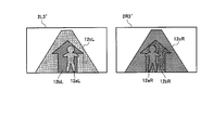
- FIG. 20 shows an image 2L3 (corresponding to the second image) captured with the exposure of the imaging system 2L adjusted to the dark subject 12b and the exposure of the imaging system 2R adjusted to the bright subjects 12a and 12c.
- An image 2R3 (corresponding to the first image) is shown.
- the bright subject images 12aL and 12cL are whiteout
- the dark subject image 12bR is blacked out.
- the dark subject 12b may use the pixel values of the dark subject image 12bL of the image 2L3, and the bright subjects 12a and 12c may use the pixel values of the bright subject images 12aR and 12cR of the image 2R3. .
- the image 2L3 ′ in FIG. 21 shows the area (12bL) captured with appropriate exposure in the image 2L3 in FIG. 20 in dark gray, and the areas that are overexposed (12aL, 12cL) in diagonal lines. It is.
- the image 2R3 ′ in FIG. 21 shows the regions (12aR, 12cR) captured with appropriate exposure in the image 2R3 in FIG. 20 in light gray, and the blacked regions (12bR) in diagonal lines. It is.
- a part of the dark subject 12b becomes a shadow of the bright subject 12a
- a part of the bright subject 12c becomes a shadow of the dark subject 12b.
- the regions 12aL and 12cL of the image 2L3 are whiteout, it is desirable to use the pixel values of the regions 12aR and 12cR of the image 2R3.
- a blackened region 12bR is included in a part of the region 12cR of the image 2R3. Yes, there is no corresponding pixel. Therefore, when the image 2L3 and the image 2R3 in FIG. 20 are combined, an occlusion region O2 (shaded region) as shown in FIG. 22 is generated.
- the areas of the bright subject images 12aL and 12cL are not captured with appropriate exposure, and are whiteout areas.
- the areas of the bright subject images 12aR and 12cR are captured with appropriate exposure.
- the parallax of each subject is calculated between the images 2L3 and 2R3.
- the pixel value of the region shifted by this amount of parallax corresponds to the pixel value of the region of the bright subject images 12aR and 12cR.
- the pixel values of the bright subject images 12aR and 12cR of the image 2R3 are assigned to the bright subject images 12aL and 12cL of the image 2L3, and image synthesis is performed.
- the bright subject image 12cR of the image 2R3 A part of the region includes a blackened region 12bR, and there is no corresponding pixel. Therefore, occlusion occurs when the images are combined (FIG. 22).
- the exposure of the reference imaging system 2L is adjusted to the dark subject 12b, and the exposure of the imaging system 2R is adjusted to the bright subject.
- the image picked up in accordance with the portions 12a and 12c (example in FIG. 22) has a small occlusion area and can suppress image quality deterioration.
- the influence of the occlusion area can be reduced by using the image 2L3 of the image 2L3 and the image 2R3, in which the exposure is adjusted to the second dark subject 12b from the front as the reference image.
- the exposure of the reference imaging system 2L is adjusted to the second bright subject from the near side, It can be said that the area where the image quality deteriorates due to occlusion can be suppressed to a smaller extent when the exposure of the imaging system 2R is imaged in accordance with a dark subject.
- the reference imaging is possible even when the bright subject, the dark subject, and the bright subject are arranged in this order from the near side, or the dark subject, the bright subject, and the dark subject are arranged in this order from the near side.
- LSI Large Scale Integration
- each functional block of the imaging apparatus may be individually chipped, or a part or all of them may be integrated into a chip.
- the method of the integrated circuit is not limited to LSI, and may be realized by a dedicated circuit or a general-purpose processor.
- processing such as parallax calculation, determination, exposure control, and image composition can be realized by hardware processing such as FPGA (Field Programmable Gate Array) or ASIC (Application Specific Integrated Circuit), or software processing by a microcomputer or the like. it can.
Abstract
Provided is an image pickup device, wherein a high-resolution composited image with an appropriate exposure can be obtained, while widening the dynamic range thereof. The image pickup device (1) is provided with: a plurality of image-pickup systems (2); a parallax calculation unit (3) for calculating parallax of a plurality of images picked up by the plurality of image-pickup systems (2); an evaluation unit (4) for evaluating the magnitude correlation and position correlation between brightness of subjects in the plurality of images; an exposure control unit (5) that is able to control the plurality of image-pickup systems (2) with different exposures, on the basis of the result of the evaluation by the evaluation unit (4); and an image compositing unit (6) for compositing the plurality of images, on the basis of the parallax calculated by the parallax calculation unit (3) and the exposure set by the exposure control unit (5).
Description
本発明は、同一被写体を異なる視点で撮像する複数の撮像系を備えた撮像装置に関する。
The present invention relates to an imaging apparatus including a plurality of imaging systems that image the same subject from different viewpoints.
近年、デジタルスチルカメラやデジタルビデオカメラなどの撮像装置の高機能化や高画質化が進んでいる。撮像画像の画質を決める要因の1つとして、ダイナミックレンジがある。カメラにおけるダイナミックレンジとは識別可能な最大輝度と最小輝度の比である。現在市販されている一般的なデジタルカメラに搭載されているCCDやCMOSなどの撮像素子のダイナミックレンジは高いものでも2000:1程度である。一方、被写体の最大輝度と最小輝度の比は、シーンによっては100000:1以上あり、そのようなシーンを撮像する場合、明部に露出を合わせると暗部の光量が不足し黒潰れし、暗部に露出を合わせると明部が飽和し白飛びしてしまうという問題がある。
In recent years, imaging devices such as digital still cameras and digital video cameras have been improved in function and image quality. One of the factors that determine the image quality of a captured image is a dynamic range. The dynamic range in a camera is the ratio of maximum and minimum brightness that can be identified. The dynamic range of an image sensor such as a CCD or CMOS mounted on a general digital camera currently on the market is about 2000: 1 even if it has a high dynamic range. On the other hand, the ratio of the maximum luminance to the minimum luminance of the subject is 100000: 1 or more depending on the scene. When shooting such a scene, if the exposure is adjusted to the bright part, the amount of light in the dark part is insufficient and the black part is crushed. When the exposure is adjusted, there is a problem that the bright part is saturated and whiteout occurs.
黒潰れや白飛びによる画質劣化を防ぐには、ダイナミックレンジを拡大する必要がある。センサ自体のダイナミックレンジを拡大する以外に、例えば、特許文献1には、露出の異なる複数の画像を合成することでダイナミックレンジを拡大する技術が提案されている。この方法では、同一の撮像系で複数回撮像するため、被写体が動体である場合には合成に用いる複数の画像にずれが生じ、合成が困難になるという問題があった。
¡In order to prevent image deterioration due to black crushing or whiteout, it is necessary to expand the dynamic range. In addition to expanding the dynamic range of the sensor itself, for example, Patent Document 1 proposes a technique for expanding the dynamic range by combining a plurality of images with different exposures. In this method, since imaging is performed a plurality of times with the same imaging system, there is a problem that when a subject is a moving object, a plurality of images used for synthesis are shifted, and synthesis is difficult.
また、動被写体撮像時のずれを回避するため、例えば、特許文献2では、複数の撮像系で被写体を同時に撮像した画像を合成する多眼式カメラが提案されている。この多眼式カメラは、被写体像の光束を受光して撮影するCCDと、CCDに被写体像を導くための複数の撮影光学系とを備え、複数の撮影光学系にそれぞれ異なる可視光透過率の光学フィルタが装着され、複数の撮影光学系からの複数の被写体像が同時に撮影される。
In order to avoid a shift at the time of moving subject imaging, for example, Patent Document 2 proposes a multi-lens camera that synthesizes images obtained by simultaneously imaging subjects with a plurality of imaging systems. This multi-lens camera includes a CCD that receives and shoots a light beam of a subject image, and a plurality of photographing optical systems that guide the subject image to the CCD. Each of the plurality of photographing optical systems has different visible light transmittance. An optical filter is attached, and a plurality of subject images from a plurality of photographing optical systems are photographed simultaneously.
しかしながら、上記特許文献2の方法は次のような課題を有している。すなわち、可視光透過率の異なるフィルタを各撮像系に備えることによって各撮像系を異なる露出に設定しているが、フィルタの可視光透過率は固定であるため、撮像するシーンに対して各撮像系の露出差が必ずしも適切にはならない。また、視点の異なる複数の画像を合成に用いる場合には、複数の画像間に視差が発生する。例えば、手前の被写体ほど視差は大きくなり、遠方にある被写体ほど視差は小さくなる。しかし、特許文献2の方法では、この視差について考慮されていないため、視点の異なる複数の画像を単純に合成してしまうと、各被写体画像に位置ずれなどが発生し合成がうまくいかない可能性がある。
However, the method of Patent Document 2 has the following problems. That is, each imaging system is provided with a filter having a different visible light transmittance, so that each imaging system is set to a different exposure. However, since the visible light transmittance of the filter is fixed, each imaging is performed for a scene to be imaged. System exposure differences are not always appropriate. In addition, when a plurality of images with different viewpoints are used for synthesis, parallax occurs between the plurality of images. For example, the parallax increases as the subject is closer to the subject, and the parallax decreases as the subject is farther away. However, in the method of Patent Document 2, since this parallax is not taken into account, if a plurality of images having different viewpoints are simply combined, there is a possibility that the subject images may be misaligned and the combination may not be successful. .
本発明は、上述のごとき実情に鑑みてなされたもので、ダイナミックレンジを広げつつ、適切な露出で高画質な合成画像を得ることができる撮像装置を提供すること、を目的とする。
The present invention has been made in view of the above circumstances, and an object of the present invention is to provide an imaging apparatus capable of obtaining a high-quality composite image with appropriate exposure while expanding the dynamic range.
上記課題を解決するために、本発明の第1の技術手段は、複数の撮像系と、該複数の撮像系により撮像された複数の画像の視差を算出する視差算出部と、前記複数の画像中の被写体の明るさの大小関係及び位置関係を判定する判定部と、前記判定部の判定結果に基づき複数の撮像系をそれぞれ異なる露出に制御可能な露出制御部と、前記視差と前記露出に基づいて前記複数の画像を合成する画像合成部とを備えることを特徴とする。
In order to solve the above-described problem, the first technical means of the present invention includes a plurality of imaging systems, a parallax calculation unit that calculates parallaxes of a plurality of images captured by the plurality of imaging systems, and the plurality of images. A determination unit that determines the magnitude relationship and positional relationship of the brightness of the subject inside, an exposure control unit that can control a plurality of imaging systems to different exposures based on the determination result of the determination unit, and the parallax and the exposure And an image composition unit that composes the plurality of images based on the image.
第2の技術手段は、第1の技術手段において、前記判定部により明るい被写体と暗い被写体とが左右に配置されていると判定された場合、前記露出制御部は、一方の撮像系の露出を明るい被写体に合わせ、他方の撮像系の露出を暗い被写体に合うよう制御することを特徴とする。
In the second technical means, in the first technical means, when the determination unit determines that a bright subject and a dark subject are arranged on the left and right, the exposure control unit determines the exposure of one imaging system. It is characterized by controlling the exposure of the other imaging system so that it matches a bright subject and a dark subject.
第3の技術手段は、第2の技術手段において、前記複数の画像は、前記一方の撮像系により明るい被写体に露出を合わせて撮像された第1の画像と、前記他方の撮像系により暗い被写体に露出を合わせて撮像された第2の画像とで構成され、前記視差算出部は、前記第1の画像と前記第2の画像とから視差を算出し、前記画像合成部は、前記視差算出部により算出された視差に基づいて画像合成する際に、前記第1の画像または前記第2の画像のいずれか一方を基準画像とし、前記基準画像の画素値が所定範囲にある領域に対しては前記基準画像の画素値を用い、また、前記基準画像の画素値が所定範囲にない領域に対しては他方の画像の前記領域に対応する領域の画素値を用いて画像合成することを特徴とする。
According to a third technical means, in the second technical means, the plurality of images include a first image picked up with exposure of a bright subject by the one imaging system and a dark subject by the other imaging system. The parallax calculation unit calculates the parallax from the first image and the second image, and the image composition unit calculates the parallax. When synthesizing an image based on the parallax calculated by the unit, one of the first image and the second image is used as a reference image, and the pixel value of the reference image is within a predetermined range. Uses the pixel value of the reference image, and, for an area where the pixel value of the reference image is not within a predetermined range, image synthesis is performed using the pixel value of the area corresponding to the area of the other image. And
第4の技術手段は、第1の技術手段において、前記判定部により明るい被写体と暗い被写体とが前後に配置されていると判定された場合、前記露出制御部は、前記画像合成部が前記複数の画像を合成する際に基準となる基準画像を撮像する撮像系の露出を後景側の被写体に合わせ、他方の撮像系の露出を前景側の被写体に合うよう制御することを特徴とする。
According to a fourth technical means, in the first technical means, when the determination unit determines that a bright subject and a dark subject are arranged before and after, the exposure control unit includes the plurality of image composition units. The exposure of the imaging system that captures the reference image serving as a reference when combining the images is adjusted to the foreground subject, and the exposure of the other imaging system is controlled to match the foreground subject.
第5の技術手段は、第4の技術手段において、前記複数の画像は、前記基準となる画像を撮像する撮像系により後景側の被写体に露出を合わせて撮像された第1の画像と、前記他方の撮像系により前景側の被写体に露出を合わせて撮像された第2の画像とで構成され、前記視差算出部は、前記第1の画像と前記第2の画像とから視差を算出し、前記画像合成部は、前記視差算出部により算出された視差に基づいて画像合成する際に、前記第1の画像の画素値が所定範囲にある領域に対しては前記第1の画像の画素値を用い、また、前記第1の画像の画素値が所定範囲にない領域に対しては前記第2の画像の前記領域に対応する領域の画素値を用いて画像合成することを特徴とする。
According to a fifth technical means, in the fourth technical means, the plurality of images are: a first image captured by an imaging system that captures the reference image and a subject on the background side being exposed. And the second image captured by the other imaging system with the foreground subject adjusted to the exposure, and the parallax calculation unit calculates the parallax from the first image and the second image. When the image composition unit composes an image based on the parallax calculated by the parallax calculation unit, the pixel of the first image is applied to an area where the pixel value of the first image is in a predetermined range. And, for an area where the pixel value of the first image is not within a predetermined range, image synthesis is performed using the pixel value of the area corresponding to the area of the second image. .
第6の技術手段は、第1の技術手段において、前記判定部により明るい被写体と暗い被写体とが奥行き方向に交互に配置されていると判定された場合、前記露出制御部は、前記画像合成部が前記複数の画像を合成する際に基準となる画像を撮像する撮像系の露出を手前の被写体とは明るさの異なる被写体に合わせ、他方の撮像系の露出を手前の被写体に合うよう制御することを特徴とする。
According to a sixth technical means, in the first technical means, when the determination unit determines that a bright subject and a dark subject are alternately arranged in the depth direction, the exposure control unit Adjusts the exposure of the imaging system that captures a reference image when combining the plurality of images to a subject having a brightness different from that of the subject in front, and controls the exposure of the other imaging system to match the subject in front It is characterized by that.
第7の技術手段は、第6の技術手段において、前記複数の画像は、前記基準となる画像を撮像する撮像系により手前の被写体とは明るさの異なる被写体に露出を合わせて撮像された第1の画像と、前記他方の撮像系により手前の被写体に露出を合わせて撮像された第2の画像とで構成され、前記視差算出部は、前記第1の画像と前記第2の画像とから視差を算出し、前記画像合成部は、前記視差算出部により算出された視差に基づいて画像合成する際に、前記第1の画像の画素値が所定範囲にある領域に対しては前記第1の画像の画素値を用い、また、前記第1の画像の画素値が所定範囲にない領域に対しては前記第2の画像の前記領域に対応する領域の画素値を用いて画像合成することを特徴とする。
According to a seventh technical means, in the sixth technical means, the plurality of images are picked up by an image pickup system for picking up the reference image, with a subject having a brightness different from that of a subject in front of the subject, with exposure adjusted. 1 image and a second image captured by the other imaging system with an exposure of the subject in front, and the parallax calculation unit includes the first image and the second image. The parallax is calculated, and the image synthesizing unit, when synthesizing the image based on the parallax calculated by the parallax calculating unit, for the region where the pixel value of the first image is in a predetermined range, The pixel value of the image of the first image is used, and for the region where the pixel value of the first image is not within a predetermined range, the image value is synthesized using the pixel value of the region corresponding to the region of the second image. It is characterized by.
第8の技術手段は、第2、第4、第6のいずれか1の技術手段において、前記露出制御部は、前記複数の撮像系を同じ露出に制御し、前記視差算出部は、前記露出制御部により同じ露出に制御された前記複数の撮像系により撮像された複数の画像の視差を算出し、前記判定部は、前記複数の画素の画素値に基づいて各被写体の明るさの大小関係を判定し、前記視差算出部により算出された各被写体の視差に基づいて各被写体の位置関係を判定することを特徴とする。
The eighth technical means is the technical means according to any one of the second, fourth and sixth technical means, wherein the exposure control unit controls the plurality of imaging systems to have the same exposure, and the parallax calculation unit comprises the exposure. The parallax of a plurality of images captured by the plurality of imaging systems controlled to the same exposure by the control unit is calculated, and the determination unit determines the magnitude relationship of the brightness of each subject based on the pixel values of the plurality of pixels And determining the positional relationship of each subject based on the parallax of each subject calculated by the parallax calculation unit.
本発明によれば、視点の異なる複数の画像を撮像する際に、各撮像系毎の露出を被写体に応じて適切に制御すると共に、得られた複数の画像を視差に基づいて合成することにより、ダイナミックレンジを広げつつ、暗部から明部まで露出の合った高画質な合成画像を得ることが可能となる。
According to the present invention, when capturing a plurality of images with different viewpoints, the exposure for each imaging system is appropriately controlled according to the subject, and the obtained images are synthesized based on parallax. It is possible to obtain a high-quality composite image in which exposure is matched from the dark part to the bright part while expanding the dynamic range.
以下、添付図面を参照しながら、本発明の撮像装置に係る好適な実施の形態について説明する。
Hereinafter, preferred embodiments of the imaging apparatus of the present invention will be described with reference to the accompanying drawings.
図1は、本発明の一実施形態に係る撮像装置の構成例を示すブロック図である。図中、1は撮像装置を示す。撮像装置1は、同一被写体を異なる視点で撮像する複数の撮像系2を備える。この撮像系2は、本例では左右に2つ配置され、固体撮像素子の一例であるCCD(Charge Coupled Device)と、CCDに被写体像を導くための撮影光学系とで構成される。固体撮像素子としては、CCDに限らず、CMOSであってもよいが、以下ではCCDを代表例として説明する。また、撮像装置1は、複数の撮像系2により撮像された複数の画像の視差を算出する視差算出部3と、複数の画像中の被写体の明るさの大小関係及び位置関係を判定する判定部4と、判定部4の判定結果に基づき複数の撮像系2をそれぞれ異なる露出に制御可能な露出制御部5と、視差算出部3で算出した視差と露出制御部5で設定した露出に基づいて複数の画像を合成する画像合成部6とを備える。
FIG. 1 is a block diagram illustrating a configuration example of an imaging apparatus according to an embodiment of the present invention. In the figure, reference numeral 1 denotes an imaging device. The imaging device 1 includes a plurality of imaging systems 2 that image the same subject from different viewpoints. In this example, two imaging systems 2 are arranged on the left and right, and are constituted by a CCD (Charge Coupled Device) which is an example of a solid-state imaging device and a photographing optical system for guiding a subject image to the CCD. The solid-state imaging device is not limited to a CCD but may be a CMOS, but a CCD will be described below as a representative example. In addition, the imaging apparatus 1 includes a parallax calculation unit 3 that calculates parallaxes of a plurality of images captured by a plurality of imaging systems 2, and a determination unit that determines a magnitude relationship and a positional relationship between the brightness of subjects in the plurality of images. 4, based on the exposure control unit 5 that can control the plurality of imaging systems 2 to different exposures based on the determination result of the determination unit 4, the parallax calculated by the parallax calculation unit 3, and the exposure set by the exposure control unit 5 And an image composition unit 6 that composes a plurality of images.
すなわち、判定部4は、同一被写体に含まれる2つ以上の被写体に対して各被写体の明るさの大小関係及び各被写体の位置関係を判定する。露出制御部5は、判定部4の判定結果に基づいて複数の撮像系2をそれぞれ異なる露出に制御する。視差算出部3は、露出制御部5で異なる露出に制御された複数の撮像系2により撮像された複数の画像から視差を算出する。画像合成部6は、視差算出部3で算出した視差に基づいて複数の画像を合成する。
That is, the determination unit 4 determines the magnitude relationship of the brightness of each subject and the positional relationship of each subject with respect to two or more subjects included in the same subject. The exposure control unit 5 controls the plurality of imaging systems 2 to different exposures based on the determination result of the determination unit 4. The parallax calculation unit 3 calculates the parallax from a plurality of images captured by the plurality of imaging systems 2 controlled to different exposures by the exposure control unit 5. The image synthesis unit 6 synthesizes a plurality of images based on the parallax calculated by the parallax calculation unit 3.
図2は、本発明の撮像装置による画像合成方法の一例を説明するためのフロー図である。まず、撮像装置1の露出制御部5は、左右2つの撮像系2L,2Rを同じ露出に制御し、これら2つの撮像系2L,2Rにより同一被写体を撮像する(ステップS1)。この同一被写体には明るさの異なる2つ以上の被写体が含まれているものとする。また、ステップS1で撮像された同一被写体の左右の画像情報は視差算出部3及び判定部4に入力される。次に、視差算出部3は、撮像系2L,2Rにより入力された左右の画像情報から各被写体の視差を算出する(ステップS2)。この視差の算出には例えば後述するブロックマッチング法を利用することができる。
FIG. 2 is a flowchart for explaining an example of an image composition method by the imaging apparatus of the present invention. First, the exposure control unit 5 of the imaging apparatus 1 controls the left and right imaging systems 2L and 2R to the same exposure, and images the same subject using these two imaging systems 2L and 2R (step S1). It is assumed that the same subject includes two or more subjects having different brightness. Also, the left and right image information of the same subject captured in step S <b> 1 is input to the parallax calculation unit 3 and the determination unit 4. Next, the parallax calculation unit 3 calculates the parallax of each subject from the left and right image information input by the imaging systems 2L and 2R (step S2). For this parallax calculation, for example, a block matching method described later can be used.
次に、判定部4は、撮像系2L,2Rより入力された左右の画像情報から例えば画素値(RGB値)を取得し、取得した画素値に基づいて各被写体の明るさの大小関係を判定すると共に、視差算出部3で算出された各被写体の視差に基づいて各被写体の位置関係(配置関係ともいう)を判定する(ステップS3)。各被写体の明るさの大小関係は、各被写体毎の画素値(RGB)をY値(YCbCr)に変換し、例えば各被写体の明るさの平均値を比較することで、相対的に明るい被写体と暗い被写体とを判定できる。また、各被写体の配置関係は、撮像系2L,2Rから見て、手前の被写体ほど視差が大きく、遠方の被写体ほど視差が小さいという関係から、各被写体の視差が異なっていれば、各被写体は前後に配置されており、また、各被写体の視差が同じであれば、各被写体は左右に配置されていると判定できる。
Next, the determination unit 4 acquires, for example, pixel values (RGB values) from the left and right image information input from the imaging systems 2L and 2R, and determines the magnitude relationship of the brightness of each subject based on the acquired pixel values. At the same time, based on the parallax of each subject calculated by the parallax calculation unit 3, the positional relationship (also referred to as arrangement relationship) of each subject is determined (step S3). The brightness relationship of each subject is obtained by converting the pixel value (RGB) for each subject into a Y value (YCbCr) and comparing the average value of the brightness of each subject, for example, with a relatively bright subject. A dark subject can be determined. In addition, the disposition relationship of each subject is such that, when viewed from the imaging systems 2L and 2R, the disparity of each subject is different if the disparity of each subject is different. If the parallax of each subject is the same and the parallax of each subject is the same, it can be determined that each subject is located on the left and right.
次に、判定部4による判定の結果(ステップS4)、左右に明るい被写体と暗い被写体が配置されていると判定された場合(図中、左右明暗の場合)、露出制御部5は、一方の撮像系の露出を明るい被写体に合わせ、他方の撮像系の露出を暗い被写体に合わせる(ステップS5)。また、前後に明るい被写体と暗い被写体が配置されていると判定された場合(図中、前後明暗の場合)、露出制御部5は、一方の撮像系の露出を後景側の明るい被写体(又は暗い被写体)に合わせ、他方の撮像系の露出を前景側の暗い被写体(又は明るい被写体)に合わせる(ステップS6)。そして、ステップS5またはステップS6で異なる露出に制御された撮像系2L,2Rにより同一被写体を撮像する。この同一被写体を撮像して得られた左右の画像情報は視差算出部3及び画像合成部6に入力される。
Next, as a result of the determination by the determination unit 4 (step S4), when it is determined that a bright subject and a dark subject are arranged on the left and right (in the case of left and right light and dark in the figure), the exposure control unit 5 The exposure of the imaging system is adjusted to a bright subject, and the exposure of the other imaging system is adjusted to a dark subject (step S5). In addition, when it is determined that a bright subject and a dark subject are arranged in front and back (in the case of front and rear bright and dark in the figure), the exposure control unit 5 sets the exposure of one imaging system to a bright subject on the background (or The exposure of the other imaging system is adjusted to the dark subject (or bright subject) on the foreground side (step S6). Then, the same subject is imaged by the imaging systems 2L and 2R controlled to different exposures in step S5 or step S6. The left and right image information obtained by imaging the same subject is input to the parallax calculation unit 3 and the image synthesis unit 6.
次に、視差算出部3は、撮像系2L,2Rにより入力された左右の画像情報から各被写体の視差を算出する(ステップS7)。そして、画像合成部6は、視差算出部3で算出された各被写体の視差に基づいて撮像系2L,2Rにより入力された左右2つの画像情報を1つの画像に合成する(ステップS8)。このフローにおいて、ステップS1では、撮像系2L,2Rを同じ露出に設定しているが、これは、視差をより正しく算出し、この視差に基づいて撮像系2L,2Rに最適な露出を設定するためである。また、ステップS8で画像合成処理に用いる視差は、各フレームにおいて異なる露出で撮像された左右画像から算出されるものである。つまり、最初の1フレームのみ各撮像系毎に最適な露出を設定するために同じ露出で行う撮像と、さらに、決定した各撮像系毎の異なる露出に基づき合成画像を得るために行う撮像と計2回撮像されるが、2フレーム以降は同じ露出での撮像は必要ないため、各撮像系毎の異なる露出による1回のみの撮像となる。
Next, the parallax calculation unit 3 calculates the parallax of each subject from the left and right image information input by the imaging systems 2L and 2R (step S7). Then, the image synthesis unit 6 synthesizes the left and right image information input by the imaging systems 2L and 2R into one image based on the parallax of each subject calculated by the parallax calculation unit 3 (step S8). In this flow, the imaging systems 2L and 2R are set to the same exposure in step S1, but this calculates the parallax more correctly and sets the optimal exposure for the imaging systems 2L and 2R based on this parallax. Because. In addition, the parallax used for the image composition process in step S8 is calculated from the left and right images captured with different exposures in each frame. In other words, in order to set an optimal exposure for each imaging system in only the first frame, imaging performed with the same exposure, and further, imaging performed in order to obtain a composite image based on different exposures determined for each imaging system. Although imaging is performed twice, since imaging with the same exposure is not required after two frames, imaging is performed only once with different exposure for each imaging system.
<第1の実施形態>
本発明の第1の実施形態では、判定部4により明るい被写体と暗い被写体とが左右に配置されていると判定された場合、露出制御部5は、一方の撮像系の露出を明るい被写体に合わせ、他方の撮像系の露出を暗い被写体に合わせて制御する。なお、判定部4は、図2のフローで説明したように、同じ露出で撮像した左右の画像情報から各被写体の明るさと視差を取得し、これに基づいて各被写体の明るさの大小関係と各被写体の配置関係を判定してもよいし、あるいは、各被写体の明るさを輝度計などの測光センサを用いて取得し、各被写体までの距離情報を測距センサにより取得してもよい。また、距離情報については、焦点距離や撮像素子(CCDセンサ)の画素ピッチ等の撮像系の仕様が既知であれば、各被写体の視差から算出してもよい。このようにして得られた被写体の明るさ及び距離情報に基づいて、各被写体の明るさの大小関係と各被写体の配置関係を判定してもよい。 <First Embodiment>
In the first embodiment of the present invention, when the determination unit 4 determines that a bright subject and a dark subject are arranged on the left and right, theexposure control unit 5 adjusts the exposure of one imaging system to the bright subject. The exposure of the other imaging system is controlled in accordance with a dark subject. Note that, as described in the flow of FIG. 2, the determination unit 4 acquires the brightness and parallax of each subject from the left and right image information captured with the same exposure, and based on this, the magnitude relationship between the brightness of each subject. The arrangement relationship of each subject may be determined, or the brightness of each subject may be obtained using a photometric sensor such as a luminance meter, and distance information to each subject may be obtained by the distance measuring sensor. The distance information may be calculated from the parallax of each subject if the imaging system specifications such as the focal length and the pixel pitch of the imaging device (CCD sensor) are known. Based on the brightness and distance information of the subject thus obtained, the magnitude relationship of the brightness of each subject and the arrangement relationship of each subject may be determined.
本発明の第1の実施形態では、判定部4により明るい被写体と暗い被写体とが左右に配置されていると判定された場合、露出制御部5は、一方の撮像系の露出を明るい被写体に合わせ、他方の撮像系の露出を暗い被写体に合わせて制御する。なお、判定部4は、図2のフローで説明したように、同じ露出で撮像した左右の画像情報から各被写体の明るさと視差を取得し、これに基づいて各被写体の明るさの大小関係と各被写体の配置関係を判定してもよいし、あるいは、各被写体の明るさを輝度計などの測光センサを用いて取得し、各被写体までの距離情報を測距センサにより取得してもよい。また、距離情報については、焦点距離や撮像素子(CCDセンサ)の画素ピッチ等の撮像系の仕様が既知であれば、各被写体の視差から算出してもよい。このようにして得られた被写体の明るさ及び距離情報に基づいて、各被写体の明るさの大小関係と各被写体の配置関係を判定してもよい。 <First Embodiment>
In the first embodiment of the present invention, when the determination unit 4 determines that a bright subject and a dark subject are arranged on the left and right, the
そして、上記により異なる露出に制御された撮像系2L,2Rによって同一の被写体が撮像される。従って、画像合成に用いる複数の画像は、一方の撮像系により明るい被写体に露出を合わせて撮像された第1の画像と、他方の撮像系により暗い被写体に露出を合わせて撮像された第2の画像とで構成される。視差算出部3は、第1の画像と第2の画像とから視差を算出し、画像合成部6は、視差算出部3により算出された視差に基づいて画像合成する際に、第1の画像または第2の画像のいずれか一方を基準画像とし、基準画像の画素値が所定範囲にある領域に対しては基準画像の画素値を用い、また、基準画像の画素値が所定範囲にない領域に対しては他方の画像の当該領域に対応する領域の画素値を用いて画像合成する。以下、第1の実施形態について具体例を示して説明する。
Then, the same subject is imaged by the imaging systems 2L and 2R controlled to different exposures as described above. Accordingly, the plurality of images used for image composition are the first image that is imaged with the exposure of a bright subject by one imaging system and the second image that is imaged with the exposure of a dark subject by the other imaging system. It consists of images. The parallax calculation unit 3 calculates the parallax from the first image and the second image, and the image synthesis unit 6 performs the first image when synthesizing the image based on the parallax calculated by the parallax calculation unit 3. Alternatively, one of the second images is used as a reference image, the pixel value of the reference image is used for an area where the pixel value of the reference image is in a predetermined range, and the area where the pixel value of the reference image is not in the predetermined range In contrast, image synthesis is performed using the pixel values of the region corresponding to the region of the other image. Hereinafter, the first embodiment will be described with a specific example.
図3は、左右に配置された2つの撮像系2L,2Rを用いて、左右に配置された明るい被写体(明部)と暗い被写体(暗部)を撮像する場合の一例を模式的に示した図である。図中、10aは明るい被写体(以下、明被写体)、10bは暗い被写体(以下、暗被写体)を示す。また、図4に、撮像系2Lの露出を明被写体10aに合わせて撮像した画像2L1と、同じく撮像系2Lの露出を暗被写体10bに合わせて撮像した画像2L2とを示す。明被写体10aと暗被写体10bの輝度比が撮像系2Lのダイナミックレンジより広いため、露出を明被写体10aに合わせると画像2L1に示すように暗被写体画像10bLが黒潰れし、露出を暗被写体10bに合わせると画像2L2に示すように明被写体画像10aLが白飛びしてしまう。
FIG. 3 is a diagram schematically illustrating an example of imaging a bright subject (bright portion) and a dark subject (dark portion) arranged on the left and right using the two imaging systems 2L and 2R arranged on the left and right. It is. In the figure, 10a indicates a bright subject (hereinafter, bright subject) and 10b indicates a dark subject (hereinafter, dark subject). FIG. 4 shows an image 2L1 that is captured with the exposure of the imaging system 2L adjusted to the bright subject 10a, and an image 2L2 that is also captured with the exposure of the imaging system 2L adjusted to the dark subject 10b. Since the luminance ratio of the bright subject 10a and the dark subject 10b is wider than the dynamic range of the imaging system 2L, when the exposure is adjusted to the bright subject 10a, the dark subject image 10bL is crushed black as shown in the image 2L1, and the exposure is changed to the dark subject 10b. When combined, the bright subject image 10aL is overexposed as shown in the image 2L2.
そこで、本実施形態では、一方の撮像系2Lの露出を明被写体10aに合わせて撮像し、他方の撮像系2Rの露出を暗被写体10bに合わせて撮像し、両方の撮像画像を合成することにより、明部から暗部まで白飛びや黒潰れのない露出の合った画像を得るようにしている。
Therefore, in the present embodiment, the exposure of one imaging system 2L is imaged according to the bright subject 10a, the exposure of the other imaging system 2R is imaged according to the dark subject 10b, and both the captured images are synthesized. Thus, an image with a well-exposed image without whiteout or blackout is obtained from the bright part to the dark part.
図5に、撮像系2Lの露出を明被写体10aに合わせて撮像した画像2L1と、撮像系2Rの露出を暗被写体10bに合わせて撮像した画像2R1を示す。画像2L1と画像2R1は本発明の第1の画像と第2の画像に相当するものとする。露出の設定方法は、既知の技術として、例えば、画像の平均画素値が所定の値となるようにする方法や、画像の最大画素値あるいは最小画素値が所定の値となるようにする方法などが知られている。また、画像合成用の視差をより正しく算出するためには、撮像系2Lの撮像画像に黒潰れ領域がなく、撮像系2Rの撮像画像に白飛び領域がないほうがよいため、両撮像系の露出差をあまり大きくとらないほうが望ましい。露出は、撮像装置1の絞り、感度、シャッタ速度等を制御することで設定することが出来る。複数の撮像系2L,2Rの露出を独立に制御することで、撮像するシーンに適した露出差に設定することが出来る。
FIG. 5 shows an image 2L1 obtained by capturing the exposure of the imaging system 2L with the bright subject 10a and an image 2R1 obtained by capturing the exposure of the imaging system 2R with the dark subject 10b. The image 2L1 and the image 2R1 correspond to the first image and the second image of the present invention. As a known technique, for example, a method for setting the average pixel value of the image to a predetermined value or a method for setting the maximum pixel value or the minimum pixel value of the image to a predetermined value is known. It has been known. Further, in order to calculate the parallax for image synthesis more correctly, it is better that the captured image of the imaging system 2L does not have a blackout area and the captured image of the imaging system 2R does not have a whiteout area. It is desirable not to make the difference too large. The exposure can be set by controlling the aperture, sensitivity, shutter speed, and the like of the imaging apparatus 1. By independently controlling the exposure of the plurality of imaging systems 2L and 2R, it is possible to set an exposure difference suitable for the scene to be imaged.
次に、画像合成に用いる視差の算出方法について述べる。図5の画像2L1と画像2R1とでは被写体像の位置が異なるように、視点の異なる撮像系2L,2Rで撮像された画像には視差がある。例えば、光軸が平行な2つの撮像系で撮像した場合、手前にある被写体ほど視差が大きくなり、遠方にある被写体ほど視差が小さくなり、無限遠にある被写体の視差はゼロとなる。従って、画像合成の際には視差を補正して合成する必要がある。なお、本例の場合、2つの被写体10a,10bは、撮像系2L,2Rから等距離にあるため、それぞれの視差は等しいと判定される。従って、2つの被写体10a,10bのいずれか一方の視差を算出すればよい。
Next, a method for calculating parallax used for image composition will be described. The images captured by the imaging systems 2L and 2R with different viewpoints have parallax so that the image 2L1 and the image 2R1 in FIG. 5 have different subject image positions. For example, when imaging is performed with two imaging systems in which the optical axes are parallel, the parallax is larger as the subject is closer to the subject, the parallax is smaller as the subject is farther away, and the parallax of the subject at infinity is zero. Therefore, it is necessary to correct the parallax when combining images. In this example, since the two subjects 10a and 10b are equidistant from the imaging systems 2L and 2R, it is determined that their parallax is equal. Therefore, the parallax of either one of the two subjects 10a and 10b may be calculated.
視差を算出する方法としては、例えば、公知の技術として、ブロックマッチング法がある。ブロックマッチング法とは、画像間の類似度を評価する方法であり、一方の画像からある領域を選択し、その領域と最も類似度の高い領域を他方の画像から選択し、一方の画像から選択された領域と他方の画像から選択された最も類似度の高い領域との位置のずれが視差となる。類似度の評価には様々な評価関数が用いられる。例えば、SAD(Sum of Absolute Difference)と言われる、両画像の画素値または輝度値の差異の絶対値の総和が最小となる領域を最も類似度の高い領域として選択する方法がある。
As a method for calculating parallax, for example, there is a block matching method as a known technique. The block matching method is a method for evaluating the similarity between images. Select a region from one image, select a region with the highest similarity to that region from the other image, and select from one image. The shift in position between the selected region and the region with the highest similarity selected from the other image is parallax. Various evaluation functions are used to evaluate the similarity. For example, there is a method called SAD (Sum of Absolute Difference), which selects a region having the smallest sum of absolute values of differences between pixel values or luminance values of both images as a region having the highest similarity.
ここで、異なる露出設定で撮像された画像の輝度値や画素値を用いてブロックマッチングを行う場合は、露出差を考慮し、2つの画像の対応する点の明るさが一致するよう一方の画像の輝度値や画素値を補正してからマッチングをするとよい。例えば、画像2L1と画像2R1の露出差ΔEVが2EV(Exposure Value)であり、両画像の画素値がセンサに入射する光量に対して線形である場合は、画像2L1の画素値に2のΔEV乗を掛けることで、2つの画像の対応する画素の明るさを一致させることが出来る。
Here, when performing block matching using the luminance values and pixel values of images captured with different exposure settings, one image is set so that the brightness of the corresponding points of the two images matches in consideration of the exposure difference. It is preferable to perform matching after correcting the luminance value and the pixel value. For example, when the exposure difference ΔEV between the image 2L1 and the image 2R1 is 2EV (Exposure Value) and the pixel value of both images is linear with respect to the amount of light incident on the sensor, the pixel value of the image 2L1 is multiplied by 2 EV. By multiplying, the brightness of the corresponding pixels of the two images can be matched.
図6に、画像2L1と画像2R1の対応する点の明るさが一致するよう画像2L1の画素値を補正した画像2L1′を示す。このようにして、明るさの一致した画像2L1′と画像2R1とを用いてブロックマッチングを行えばよい。なお、EVとは、log2{(絞り値の2乗)/(シャッタ速度)}で与えられる露出設定値であり、絞り値が1.0、シャッタ速度が1.0秒のときの状態が0.0EVである。
FIG. 6 shows an image 2L1 ′ obtained by correcting the pixel values of the image 2L1 so that the brightness of corresponding points in the image 2L1 and the image 2R1 match. In this way, block matching may be performed using the images 2L1 ′ and 2R1 having the same brightness. EV is an exposure setting value given by log 2 {(square of aperture value) / (shutter speed)}, and the state when the aperture value is 1.0 and the shutter speed is 1.0 second is 0. .0EV.
次に、画像を合成する方法について述べる。露出の異なる複数の画像を合成する場合、いずれか一方の画像を基準画像とし、この基準画像において適切な露出で撮像された領域については、基準画像の画素値を用い、基準画像において露出が適切でない領域については、他方の画像の当該領域に対応する領域の画素値を用いることで、明部から暗部まで適切な露出で撮像された画像を合成することが出来る。例えば、図5の画像2L1と画像2R1を、画像2L1を基準として合成する場合、明被写体10aについては画像2L1の明被写体画像10aLの画素値をそのまま用い、暗被写体10bについては画像2R1の暗被写体画像10bRの画素値を用いることで、図7に示すように、明被写体10a、暗被写体10b共に適切な露出で撮像された合成画像2LR1を得ることが出来る。
Next, a method for synthesizing images will be described. When combining multiple images with different exposures, use one of the images as the reference image, and use the pixel value of the reference image for the area captured with appropriate exposure in this reference image, and use the reference image for appropriate exposure. For a region that is not, by using the pixel value of the region corresponding to the region of the other image, it is possible to synthesize an image captured with appropriate exposure from the bright part to the dark part. For example, when the image 2L1 and the image 2R1 in FIG. 5 are combined based on the image 2L1, the pixel value of the bright subject image 10aL of the image 2L1 is used as it is for the bright subject 10a, and the dark subject of the image 2R1 is used for the dark subject 10b. By using the pixel value of the image 10bR, as shown in FIG. 7, it is possible to obtain a composite image 2LR1 that is captured with appropriate exposure for both the bright subject 10a and the dark subject 10b.
基準画像において適切な露出で撮像されているか否かを判断する方法としては、例えば、8ビットの画像(最大画素値が255)とした場合、画素値RGBの最大値が例えば250以上である場合、又は、画素値RGBの最小値が例えば5以下である場合に露出が適切でないと判定することができる。露出が適切であるか否かを判断するための閾値については、撮像系の仕様、特性等を考慮して適切な閾値を設定すればよい。なお、画像合成する際には、ブロックマッチング法により視差を算出する場合と同様、露出差を考慮する必要がある。例えば、画像2R1の画素を合成に用いる場合は、画像2R1の画素値を2のΔEV乗で割ることで、画像2L1の対応する画素の明るさと一致させることができる。
As a method for determining whether or not the reference image is captured with appropriate exposure, for example, when an 8-bit image (maximum pixel value is 255) is used, the maximum value of the pixel value RGB is, for example, 250 or more. Alternatively, it can be determined that the exposure is not appropriate when the minimum pixel value RGB is, for example, 5 or less. As for the threshold value for determining whether or not the exposure is appropriate, an appropriate threshold value may be set in consideration of the specifications and characteristics of the imaging system. Note that, when combining images, it is necessary to consider the exposure difference as in the case of calculating parallax by the block matching method. For example, when the pixel of the image 2R1 is used for composition, the pixel value of the image 2R1 can be matched with the brightness of the corresponding pixel of the image 2L1 by dividing the pixel value of the image 2R1 by 2 to the power of ΔEV.
ここで、ブロックマッチング法による視差算出についてより詳細に説明する。前述のように、画像合成時に、異なる露出設定で撮像された画像の画素値を用いてブロックマッチング法により視差を算出する場合、画像間の露出差を考慮し、両画像の対応する点の明るさが一致するよう一方の画像の輝度値または画素値を補正してからマッチングをするとよい。しかしながら、両画像の露出差が大きい場合には以下に述べる問題が生じる。
Here, the parallax calculation by the block matching method will be described in more detail. As described above, when parallax is calculated by the block matching method using pixel values of images captured with different exposure settings at the time of image synthesis, the exposure difference between the images is taken into account, and the brightness of the corresponding points of both images is considered. It is preferable to perform matching after correcting the luminance value or pixel value of one image so that the images match. However, when the exposure difference between the two images is large, the following problem occurs.
図8に、撮像系2L,2Rの撮像可能な輝度範囲を示す。撮像2Lの露出は明部に、撮像系2Rの露出は暗部に合わせて撮像している。図中、暗部(低輝度部分)は撮像系2Lでは黒潰れしており、明部(高輝度部分)は撮像系2Rでは白飛びしており、斜線(ハッチング)部は両撮像系2L,2Rで重複する輝度範囲である。この斜線部の輝度範囲においては、両撮像系で撮像された画像の露出差を補正することでブロックマッチングを行い、視差を算出することが出来る。しかしながら、撮像系2Lにおける黒潰れ領域では、画素値が0であれば補正不可能であり、0でなくともノイズが多いために補正しても正しい視差を算出することが困難な場合がある。また、同様に、撮像系2Rにおける白飛び領域では、画素値が255であれば適切に補正することが出来ず、正しい視差を算出することが困難な場合がある。
FIG. 8 shows luminance ranges that can be imaged by the imaging systems 2L and 2R. The exposure of the imaging 2L is taken in the bright part, and the exposure of the imaging system 2R is taken in the dark part. In the drawing, the dark portion (low luminance portion) is blacked out in the imaging system 2L, the bright portion (high luminance portion) is overexposed in the imaging system 2R, and the hatched portion is hatched in both imaging systems 2L and 2R. This is the overlapping luminance range. In the shaded area, the parallax can be calculated by performing block matching by correcting the exposure difference between the images captured by both imaging systems. However, in a blackout area in the imaging system 2L, correction is impossible if the pixel value is 0, and even if it is not 0, there is a lot of noise, and it may be difficult to calculate correct parallax even if correction is performed. Similarly, in the whiteout region in the imaging system 2R, if the pixel value is 255, it cannot be corrected appropriately, and it may be difficult to calculate the correct parallax.
従って、画像合成時に正しい視差を算出するためには、両撮像系ともに黒潰れ領域または白飛び領域がなるべく発生しないように撮像時の露出が適切に制御されることが望ましい。具体的には、両撮像系における撮像可能輝度範囲の重複部分が多くなるように、両撮像系の露出差を小さく制御することが考えられる。なお、両撮像系に対して適切な露出を設定するために、各被写体の明るさと視差(距離)が必要となる。このため本実施形態では、まず、両撮像系2L,2Rを同じ露出に設定して同一被写体を撮像し、得られた左右の撮像画像から各被写体の明るさと視差を算出する。そして、算出した明るさと視差に基づいて両撮像系2L,2Rの露出をシーンに合わせて適切に制御する。このように同じ露出に設定することで、より正しい視差を求めることができる。
Therefore, in order to calculate the correct parallax at the time of image synthesis, it is desirable that the exposure at the time of imaging is appropriately controlled so that a blackout area or a whiteout area does not occur as much as possible in both imaging systems. Specifically, it is conceivable to control the exposure difference between the two imaging systems to be small so that the overlapping range of the imageable luminance ranges in both imaging systems increases. Note that the brightness and parallax (distance) of each subject are required to set appropriate exposure for both imaging systems. For this reason, in this embodiment, first, both imaging systems 2L and 2R are set to the same exposure to image the same subject, and the brightness and parallax of each subject are calculated from the obtained left and right captured images. Based on the calculated brightness and parallax, the exposures of both imaging systems 2L and 2R are appropriately controlled according to the scene. By setting the same exposure in this way, more correct parallax can be obtained.
なお、白飛び領域、黒潰れ領域のように視差を正しく算出できない可能性がある領域については、例えば、その周辺領域において視差を正しく算出できていると判断できる領域の視差の値を用いて補間することで算出してもよい。
For areas that may not be able to calculate parallax correctly, such as whiteout areas and blackout areas, for example, interpolation is performed using the parallax values of areas that can be determined to be correctly calculated in the surrounding areas. You may calculate by doing.
また、撮像するシーンが急激に変化した場合は、視差の算出が困難になったり、露出の設定が適切でなくなったりする可能性がある。そこで、撮像するシーンが急激に変化した場合は、一旦撮像系2L,2Rを同じ露出設定にし、明るさと視差を算出した後、再度、それぞれの撮像系2L,2Rの露出を適切に設定してもよい。
In addition, when the scene to be imaged changes suddenly, it may be difficult to calculate the parallax or the exposure setting may not be appropriate. Therefore, when the scene to be imaged changes suddenly, the imaging systems 2L and 2R are once set to the same exposure, the brightness and the parallax are calculated, and then the exposures of the imaging systems 2L and 2R are set appropriately again. Also good.
<第2の実施形態>
本発明の第2の実施形態では、判定部4により明るい被写体と暗い被写体とが前後に配置されていると判定された場合、露出制御部5は、一方の撮像系の露出を後景側の被写体に合わせ、他方の撮像系の露出を前景側の被写体に合わせて制御する。そして、異なる露出に制御された撮像系2L,2Rにより同一の被写体が撮像される。従って、画像合成に用いる複数の画像は、一方の撮像系により後景側の被写体に露出を合わせて撮像された第1の画像と、他方の撮像系により前景側の被写体に露出を合わせて撮像された第2の画像とで構成される。視差算出部3は、第1の画像と第2の画像とから視差を算出し、画像合成部6は、視差算出部3により算出された視差に基づいて画像合成する際に、第1の画像を基準画像とし、基準画像の画素値が所定範囲にある領域に対しては基準画像の画素値を用い、また、基準画像の画素値が所定範囲にない領域に対しては第2の画像の当該領域に対応する領域の画素値を用いて画像合成する。以下、第2の実施形態について具体例を示して説明する。 <Second Embodiment>
In the second embodiment of the present invention, when the determination unit 4 determines that a bright subject and a dark subject are arranged in front and back, theexposure control unit 5 sets the exposure of one imaging system on the background side. In accordance with the subject, the exposure of the other imaging system is controlled in accordance with the foreground subject. Then, the same subject is imaged by the imaging systems 2L and 2R controlled to different exposures. Accordingly, a plurality of images used for image composition are captured with the first image captured by the one imaging system with the exposure on the background object and the other imaging system with the exposure on the foreground object. And the second image. The parallax calculation unit 3 calculates the parallax from the first image and the second image, and the image synthesis unit 6 performs the first image when synthesizing the image based on the parallax calculated by the parallax calculation unit 3. Is used as the reference image, the pixel value of the reference image is used for the region where the pixel value of the reference image is in the predetermined range, and the region of the second image is used for the region where the pixel value of the reference image is not in the predetermined range. An image is synthesized using the pixel values of the area corresponding to the area. The second embodiment will be described below with a specific example.
本発明の第2の実施形態では、判定部4により明るい被写体と暗い被写体とが前後に配置されていると判定された場合、露出制御部5は、一方の撮像系の露出を後景側の被写体に合わせ、他方の撮像系の露出を前景側の被写体に合わせて制御する。そして、異なる露出に制御された撮像系2L,2Rにより同一の被写体が撮像される。従って、画像合成に用いる複数の画像は、一方の撮像系により後景側の被写体に露出を合わせて撮像された第1の画像と、他方の撮像系により前景側の被写体に露出を合わせて撮像された第2の画像とで構成される。視差算出部3は、第1の画像と第2の画像とから視差を算出し、画像合成部6は、視差算出部3により算出された視差に基づいて画像合成する際に、第1の画像を基準画像とし、基準画像の画素値が所定範囲にある領域に対しては基準画像の画素値を用い、また、基準画像の画素値が所定範囲にない領域に対しては第2の画像の当該領域に対応する領域の画素値を用いて画像合成する。以下、第2の実施形態について具体例を示して説明する。 <Second Embodiment>
In the second embodiment of the present invention, when the determination unit 4 determines that a bright subject and a dark subject are arranged in front and back, the
図9は、左右に配置された2つの撮像系2L、2Rを用いて、前後に配置された明被写体(明部)と暗被写体(暗部)を撮像する場合の一例を模式的に示した図である。図中、11aは明被写体、11bは暗被写体を示す。また、図10に、撮像系2Lの露出を明被写体11aに合わせて撮像した画像2L2と撮像系2Rの露出を暗被写体11bに合わせて撮像した画像2R2を示す。図10において、前景側の明被写体11aに合わせた画像2L2を基準とし、画像2L2と画像2R2を合成する際に、画像2L2で白飛びや黒潰れしていない適切な露出で撮像されている明被写体11aは画像2L2の明被写体画像11aLの画素値を用い、また、画像2L2で適切な露出で撮像されていない暗被写体11bは画像2R2の暗被写体画像11bRの画素値を用いればよい。これにより、図11に示すような、明部から暗部まで適切な露出で撮像された合成画像2LR2が得られる。
FIG. 9 is a diagram schematically illustrating an example of imaging a bright subject (bright portion) and a dark subject (dark portion) arranged in front and back using two imaging systems 2L and 2R arranged on the left and right. It is. In the figure, 11a indicates a bright subject and 11b indicates a dark subject. FIG. 10 shows an image 2L2 that is captured with the exposure of the imaging system 2L matched to the bright subject 11a and an image 2R2 that is captured with the exposure of the imaging system 2R matched to the dark subject 11b. In FIG. 10, when the image 2L2 and the image 2R2 are combined with the image 2L2 matched with the bright subject 11a on the foreground side as a reference, the image 2L2 is captured with an appropriate exposure that does not cause overexposure or blackout. The subject 11a may use the pixel value of the bright subject image 11aL of the image 2L2, and the dark subject 11b that is not captured with appropriate exposure in the image 2L2 may use the pixel value of the dark subject image 11bR of the image 2R2. As a result, a composite image 2LR2 captured with appropriate exposure from the bright part to the dark part as shown in FIG. 11 is obtained.
しかしながら、図11の合成画像2LR2では明被写体画像11aLの左側がオクルージョン領域Oになっており、画質が劣化するという問題がある。このオクルージョン領域Oは、図10の画像2L2では暗被写体11bが撮像されているが、画像2R2では明被写体11aが撮像されており、暗被写体11bは明被写体11aの影になっている。このように、一方の撮像系では撮像されており、他方の撮像系では撮像されていない領域をオクルージョンという。図11に白色で示すオクルージョン領域Oは、図10の画像2L2では黒潰れしているため、合成には適切な露出で撮像されている画像2R2の画素値を用いるのが好適であるが、画像2R2ではオクルージョンになっているため対応する領域に画素が存在しない。したがって、画像を合成する際、誤った画素値を合成に用いたり、露出の合っていない画像2L2の画素値を用いたりする必要があるため、画質が劣化する。
However, in the composite image 2LR2 in FIG. 11, the left side of the bright subject image 11aL is the occlusion area O, and there is a problem that the image quality deteriorates. In this occlusion area O, the dark subject 11b is captured in the image 2L2 of FIG. 10, but the bright subject 11a is captured in the image 2R2, and the dark subject 11b is a shadow of the bright subject 11a. Thus, an area that is imaged in one imaging system and not imaged in the other imaging system is referred to as occlusion. Since the occlusion region O shown in white in FIG. 11 is crushed black in the image 2L2 in FIG. 10, it is preferable to use the pixel value of the image 2R2 captured with appropriate exposure for the synthesis. Since 2R2 is occluded, there is no pixel in the corresponding region. Accordingly, when combining images, it is necessary to use an incorrect pixel value for combining or to use a pixel value of the image 2L2 that is not exposed properly, so that the image quality deteriorates.
これに対して、図12に、撮像系2Lの露出を暗被写体11bに合わせて撮像した画像2L2と撮像系2Rの露出を明被写体11aに合わせて撮像した画像2R2を示す。また、図13に画像2L2と画像2R2の合成画像を示す。図12の例の場合、上記の図10の例と異なり、遠景側の暗被写体11bに露出を合わせた画像2L2(第1の画像に相当)が基準となり、暗被写体11bは適切な露出で撮像されている画像2L2の暗被写体画像11bLの画素値を用い、また、画像2L2で適切な露出で撮像されていない明被写体11aは画像2R2(第2の画像に相当)の明被写体画像11aRの画素値を用いる。この際、図11に示すオクルージョン領域Oには、画像2L2の暗被写体画像11bLの画素が存在するため、図13に示すようにオクルージョンによる劣化は生じない。
On the other hand, FIG. 12 shows an image 2L2 obtained by taking the exposure of the imaging system 2L in accordance with the dark subject 11b and an image 2R2 obtained by taking the exposure of the imaging system 2R in accordance with the bright subject 11a. FIG. 13 shows a composite image of the image 2L2 and the image 2R2. In the example of FIG. 12, unlike the example of FIG. 10 described above, the image 2L2 (corresponding to the first image) obtained by aligning the exposure with the dark subject 11b on the far side is the reference, and the dark subject 11b is imaged with an appropriate exposure. The pixel value of the dark subject image 11bL of the image 2L2 being used, and the bright subject 11a that has not been imaged with appropriate exposure in the image 2L2 is the pixel of the bright subject image 11aR of the image 2R2 (corresponding to the second image) Use the value. At this time, since the pixels of the dark subject image 11bL of the image 2L2 are present in the occlusion area O shown in FIG. 11, deterioration due to occlusion does not occur as shown in FIG.
すなわち、図12において、画像2L2では、明被写体画像11aLの領域が適切な露出で撮像されておらず白飛び領域となっている。一方、画像2R2では、明被写体画像11aRの領域が適切な露出で撮像されている。画像2L2の明被写体画像11aLと画像2R2の明被写体画像11aRとは視差分だけずれているが、画像2L2と画像2R2間では各被写体の視差が算出されているため、画像2R2においてこの視差分だけずらした領域の画素値が明被写体画像11aRの領域の画素値に対応することになる。このようにして、画像2L2の明被写体画像11aLの領域に、画像2R2の明被写体画像11aRの領域の画素値を割り当てて、画像合成を行うことで、オクルージョンの発生を防止することができる。
That is, in FIG. 12, in the image 2L2, the area of the bright subject image 11aL is not captured with appropriate exposure and is a whiteout area. On the other hand, in the image 2R2, the area of the bright subject image 11aR is captured with appropriate exposure. The bright subject image 11aL of the image 2L2 and the bright subject image 11aR of the image 2R2 are shifted by the amount of parallax. However, since the parallax of each subject is calculated between the image 2L2 and the image 2R2, only this amount of parallax is calculated in the image 2R2. The pixel value of the shifted area corresponds to the pixel value of the area of the bright subject image 11aR. In this way, the pixel values of the bright subject image 11aR area of the image 2R2 are assigned to the bright subject image 11aL area of the image 2L2, and the image synthesis is performed, thereby preventing the occurrence of occlusion.
以上より、明るさの異なる2つの被写体が前後にある場合には、基準となる撮像系の露出を遠い側にある被写体に合わせて撮像し、他方の撮像系の露出を近い側にある被写体に合わせて撮像することで、画像合成時にオクルージョンに起因する画質の劣化を回避することが出来る。
As described above, when there are two subjects with different brightness levels, the image capturing system of the reference imaging system is imaged according to the subject on the far side, and the exposure of the other imaging system is set to the subject on the near side. By capturing the images together, it is possible to avoid image quality degradation caused by occlusion during image composition.
次に、明るさの異なる2つの被写体が前後にある場合における露出の設定方法について説明する。上述のように、明るさの異なる2つの被写体が前後にある場合は、基準となる撮像系の露出を遠い側(後景側)にある被写体に合わせ、他方の撮像系の露出を近い側(前景側)にある被写体に合わせて撮像することで、画質劣化のない画像合成を行うことができる。この際、被写体の明るさと被写体までの距離情報が必要となる。
Next, an exposure setting method in the case where two subjects having different brightness are in front and behind will be described. As described above, when two subjects with different brightness are present at the front and rear, the exposure of the reference imaging system is adjusted to the subject on the far side (background), and the exposure of the other imaging system is set to the near side ( By image-taking in accordance with the subject on the foreground side), it is possible to perform image composition without image quality deterioration. At this time, the brightness of the subject and the distance information to the subject are required.
明るさについては、例えば、CCDセンサに入射する光量に対して線形な値を持つRAWデータを用いて算出することで、おおよその輝度値を算出することが出来る。また、画像の画素値(RGB値)を用いて明るさを算出してもよい。画素値を用いる場合、正確な輝度を算出することは容易ではないが、被写体の明るさの大小の傾向を知ることは出来るため、露出を設定する際に必要な情報としては十分である。また、輝度計などの測光センサを用いてもよい。
About brightness, for example, an approximate luminance value can be calculated by calculating using RAW data having a linear value with respect to the amount of light incident on the CCD sensor. Alternatively, brightness may be calculated using pixel values (RGB values) of the image. When pixel values are used, it is not easy to calculate an accurate luminance, but since it is possible to know the tendency of the brightness of the subject, it is sufficient as information necessary for setting the exposure. Further, a photometric sensor such as a luminance meter may be used.
距離情報については、例えば、測距センサや、視差を利用して算出する方法などがある。視差を利用する場合、例えば、光軸が平行となるよう2つの撮像系を配置して撮像した場合、手前にある被写体ほど視差が大きくなり、遠方にある被写体ほど視差が小さくなり、無限遠にある被写体の視差はゼロとなる。したがって、視差の大小により被写体の前後関係を判定することが出来る。また、焦点距離やセンサの画素ピッチ等の撮像系の仕様が既知であれば、視差値から被写体までの距離を算出することも出来る。
The distance information includes, for example, a distance measuring sensor and a method of calculating using parallax. When using parallax, for example, when two imaging systems are arranged so that the optical axes are parallel, the parallax increases with the subject in the foreground, the parallax decreases with the subject in the distance, and becomes infinite. The parallax of a certain subject is zero. Therefore, the front-rear relationship of the subject can be determined based on the magnitude of the parallax. If the imaging system specifications such as the focal length and the pixel pitch of the sensor are known, the distance to the subject can be calculated from the parallax value.
次に、被写体の明るさと距離情報に基づいて撮像系の露出を設定する方法について述べる。本実施形態では、基準の撮像系の露出を後景に合わせ、他方の撮像系の露出を前景に合わせるため、例えば、各視差における明るさの平均値の情報より、ある視差値を閾値として前景と後景に分割すればよい。図14に、あるシーンの各視差における明るさの平均値の一例を示す。この例においては、視差1から6は明るさの平均値が小さく、視差7以上は明るさの平均値が大きい。したがって、前景は明るく、後景は暗いと言える。そこで、基準の撮像系の露出を後景、例えば視差6以下の領域を適切な露出(ここでは暗い被写体に合わせた露出)で撮像するよう設定し、他方の撮像系の露出を前景、例えば視差7以上の領域を適切な露出(ここでは明るい被写体に合わせた露出)で撮像するよう設定すればよい。
Next, a method for setting the exposure of the imaging system based on the brightness and distance information of the subject will be described. In this embodiment, in order to adjust the exposure of the reference imaging system to the foreground and the exposure of the other imaging system to the foreground, for example, from the information on the average value of the brightness in each parallax, a certain parallax value is used as a threshold value. And divide it into a background. FIG. 14 shows an example of an average value of brightness in each parallax of a certain scene. In this example, parallax 1 to 6 have a small average brightness value, and parallax 7 and above have a large average brightness value. Therefore, it can be said that the foreground is bright and the background is dark. Therefore, the exposure of the reference imaging system is set to capture the background, for example, an area with a parallax of 6 or less with an appropriate exposure (in this case, an exposure according to a dark subject), and the exposure of the other imaging system is set to the foreground, for example, parallax. What is necessary is just to set so that seven or more areas may be imaged with an appropriate exposure (in this case, an exposure according to a bright subject).
また、各明るさにおける平均視差の情報より前景と後景に分割してもよい。図15に、あるシーンの各明るさにおける平均視差の一例を示す。本例においては、明るい領域の平均視差が小さく、暗い領域の平均視差が大きいことから、前景は暗く、後景は明るいと判断することが出来る。したがって、基準の撮像系の露出を明部(後景)に合わせ、他方の撮像系の露出を暗部(前景)に合わせればよい。また、基準の撮像系の露出を最小視差の領域に合わせ、他方の撮像系の露出を最小視差以外の領域に合わせてもよい。また、基準の撮像系を最大視差以外の領域に合わせ、他方の撮像系を最大視差の領域に合わせてもよい。
Further, the foreground and the background may be divided based on the information of the average parallax at each brightness. FIG. 15 shows an example of the average parallax at each brightness of a certain scene. In this example, since the average parallax in the bright area is small and the average parallax in the dark area is large, it can be determined that the foreground is dark and the background is bright. Therefore, the exposure of the reference imaging system may be adjusted to the bright part (background), and the exposure of the other imaging system may be adjusted to the dark part (foreground). Further, the exposure of the reference imaging system may be adjusted to the minimum parallax area, and the exposure of the other imaging system may be adjusted to the area other than the minimum parallax. Further, the reference imaging system may be adjusted to an area other than the maximum parallax, and the other imaging system may be adjusted to the maximum parallax area.
<第3の実施形態>
本発明の第3の実施形態では、判定部4により明るい被写体と暗い被写体とが奥行き方向に交互に配置されていると判定された場合、露出制御部5は、一方の撮像系の露出を明るい被写体に合わせ、他方の撮像系の露出を暗い被写体に合わせて制御する。そして、異なる露出に制御された撮像系2L,2Rにより同一の被写体が撮像される。従って、画像合成に用いる複数の画像は、一方の撮像系により明るい被写体に露出を合わせて撮像された第1の画像と、他方の撮像系により暗い被写体に露出を合わせて撮像された第2の画像とで構成される。視差算出部3は、第1の画像と第2の画像とから視差を算出し、画像合成部6は、視差算出部3により算出された視差に基づいて画像合成する際に、第1の画像と第2の画像のうち、手前から2番目の被写体に露出を合わせた一方の画像を基準画像とし、基準画像の画素値が所定範囲にある領域に対しては基準画像の画素値を用い、また、基準画像の画素値が所定範囲にない領域に対しては他方の画像の当該領域に対応する領域の画素値を用いて画像合成する。以下、第3の実施形態について具体例を示して説明する。 <Third Embodiment>
In the third embodiment of the present invention, when the determination unit 4 determines that a bright subject and a dark subject are alternately arranged in the depth direction, theexposure control unit 5 brightens the exposure of one imaging system. The exposure of the other imaging system is controlled in accordance with the subject and in accordance with the dark subject. Then, the same subject is imaged by the imaging systems 2L and 2R controlled to different exposures. Accordingly, the plurality of images used for image composition are the first image that is imaged with the exposure of a bright subject by one imaging system and the second image that is imaged with the exposure of a dark subject by the other imaging system. It consists of images. The parallax calculation unit 3 calculates the parallax from the first image and the second image, and the image synthesis unit 6 performs the first image when synthesizing the image based on the parallax calculated by the parallax calculation unit 3. And the second image of the second image from which the exposure is adjusted to the second subject from the front is used as a reference image, and the pixel value of the reference image is used for an area where the pixel value of the reference image is in a predetermined range, For an area where the pixel value of the reference image is not within the predetermined range, image synthesis is performed using the pixel value of the area corresponding to the area of the other image. Hereinafter, the third embodiment will be described with a specific example.
本発明の第3の実施形態では、判定部4により明るい被写体と暗い被写体とが奥行き方向に交互に配置されていると判定された場合、露出制御部5は、一方の撮像系の露出を明るい被写体に合わせ、他方の撮像系の露出を暗い被写体に合わせて制御する。そして、異なる露出に制御された撮像系2L,2Rにより同一の被写体が撮像される。従って、画像合成に用いる複数の画像は、一方の撮像系により明るい被写体に露出を合わせて撮像された第1の画像と、他方の撮像系により暗い被写体に露出を合わせて撮像された第2の画像とで構成される。視差算出部3は、第1の画像と第2の画像とから視差を算出し、画像合成部6は、視差算出部3により算出された視差に基づいて画像合成する際に、第1の画像と第2の画像のうち、手前から2番目の被写体に露出を合わせた一方の画像を基準画像とし、基準画像の画素値が所定範囲にある領域に対しては基準画像の画素値を用い、また、基準画像の画素値が所定範囲にない領域に対しては他方の画像の当該領域に対応する領域の画素値を用いて画像合成する。以下、第3の実施形態について具体例を示して説明する。 <Third Embodiment>
In the third embodiment of the present invention, when the determination unit 4 determines that a bright subject and a dark subject are alternately arranged in the depth direction, the
図16は、左右に配置された2つの撮像系2L,2Rを用いて、手前側から明被写体、暗被写体、明被写体の順に配置されている被写体を撮像する場合の一例を模式的に示す図である。図中、12aは明被写体、12bは暗被写体、12cは明被写体を示す。図17に、撮像系2Lの露出を明被写体12a,12cに合わせて撮像した画像2L3と、撮像系2Rの露出を暗被写体12bに合わせて撮像した画像2R3を示す。図17において、画像2L3では暗被写体画像12bLが黒潰れしており、画像2R3では明被写体画像12aRと明被写体画像12cRが白飛びしている。画像2L3と画像2R3を合成に用いる際、明被写体12a,12cは画像2L3の明被写体画像12aL,12cLの画素値を用い、暗被写体12bは画像2R3暗被写体画像12bRの画素値を用いればよい。
FIG. 16 is a diagram schematically illustrating an example of imaging a subject arranged in the order of a bright subject, a dark subject, and a bright subject from the front side using the two imaging systems 2L and 2R arranged on the left and right. It is. In the figure, 12a indicates a bright subject, 12b indicates a dark subject, and 12c indicates a bright subject. FIG. 17 shows an image 2L3 captured with the exposure of the imaging system 2L adjusted to the bright subjects 12a and 12c, and an image 2R3 imaged with the exposure of the imaging system 2R adjusted to the dark subject 12b. In FIG. 17, in the image 2L3, the dark subject image 12bL is blacked out, and in the image 2R3, the bright subject image 12aR and the bright subject image 12cR are out of focus. When the image 2L3 and the image 2R3 are used for composition, the bright subjects 12a and 12c may use the pixel values of the bright subject images 12aL and 12cL of the image 2L3, and the dark subject 12b may use the pixel values of the image 2R3 and the dark subject image 12bR.
また、図18の画像2L3′は、図17の画像2L3で適正な露出で撮像された領域(12aL,12cL)を薄いグレーで示し、黒潰れしている領域(12bL)を斜線で示したものである。また、図18の画像2R3′は、図17の画像2R3で適正な露出で撮像された領域(12bR)を濃いグレーで示し、白飛びしている領域(12aR,12cR)を斜線で示したものである。
In addition, the image 2L3 ′ in FIG. 18 shows the areas (12aL, 12cL) captured with appropriate exposure in the image 2L3 in FIG. 17 in light gray, and the blacked areas (12bL) in diagonal lines. It is. In addition, the image 2R3 ′ in FIG. 18 shows the area (12bR) captured with appropriate exposure in the image 2R3 in FIG. 17 in dark gray, and the overexposed areas (12aR, 12cR) in diagonal lines. It is.
ここで、暗被写体12bの一部は明被写体12aの影となり、明被写体12cの一部は暗被写体12bの影となる。この際、画像2L3の領域12bLは黒潰れしているため、画像2R3の領域12bRの画素値を用いることが望ましいが、画像2R3の領域12bRの一部には白飛び領域12aRがあり、対応する画素が存在しない。従って、図17の画像2L3と画像2R3とを画像合成すると、図19に示すようなオクルージョン領域O1(斜線の領域)が発生する。
Here, a part of the dark subject 12b becomes a shadow of the bright subject 12a, and a part of the bright subject 12c becomes a shadow of the dark subject 12b. At this time, since the area 12bL of the image 2L3 is blacked out, it is desirable to use the pixel value of the area 12bR of the image 2R3. However, a part of the area 12bR of the image 2R3 has a whiteout area 12aR, and the corresponding There are no pixels. Therefore, when the image 2L3 and the image 2R3 in FIG. 17 are combined, an occlusion area O1 (hatched area) as shown in FIG. 19 is generated.
すなわち、図17において、画像2L3では、暗被写体画像12bLの領域が適切な露出で撮像されておらず黒潰れ領域となっている。一方、画像2R3では、暗被写体画像12bRの領域が適切な露出で撮像されている。画像2L2の暗被写体画像12bLと画像2R2の暗被写体画像12bRとはそれぞれの視差分だけずれているが、画像2L3と画像2R3間では各被写体の視差が算出されているため、画像2R3においてこの視差分だけずらした領域の画素値が暗被写体画像12bRの領域の画素値に対応することになる。このようにして、画像2L3の暗被写体画像12bLの領域に、画像2R3の暗被写体画像12bRの領域の画素値を割り当てて、画像合成を行うが、画像2R3の暗被写体画像12bRの領域の一部には白飛び領域12aRがあり、対応する画素が存在しないため、画像合成したときにオクルージョン(図19)となる。
That is, in FIG. 17, in the image 2L3, the area of the dark subject image 12bL is not captured with an appropriate exposure and is a blackened area. On the other hand, in the image 2R3, the area of the dark subject image 12bR is captured with appropriate exposure. The dark subject image 12bL of the image 2L2 and the dark subject image 12bR of the image 2R2 are shifted by the respective parallaxes. However, since the parallax of each subject is calculated between the image 2L3 and the image 2R3, this view in the image 2R3 The pixel value of the area shifted by the difference corresponds to the pixel value of the area of the dark subject image 12bR. In this way, the pixel values of the dark subject image 12bR of the image 2R3 are assigned to the dark subject image 12bL region of the image 2L3, and image synthesis is performed, but part of the dark subject image 12bR region of the image 2R3 is performed. Has a whiteout region 12aR, and there is no corresponding pixel, so that occlusion (FIG. 19) occurs when images are combined.
これに対して、図20に、撮像系2Lの露出を暗被写体12bに合わせて撮像した画像2L3(第2の画像に相当)と、撮像系2Rの露出を明被写体12a,12cに合わせて撮像した画像2R3(第1の画像に相当)を示す。図20において、画像2L3では明被写体画像12aL,12cLが白飛びしており、画像2R3では暗被写体画像12bRが黒潰れしている。画像2L3と画像2R3を合成に用いる際、暗被写体12bは画像2L3の暗被写体画像12bLの画素値を用い、明被写体12a,12cは画像2R3の明被写体画像12aR,12cRの画素値を用いればよい。
On the other hand, FIG. 20 shows an image 2L3 (corresponding to the second image) captured with the exposure of the imaging system 2L adjusted to the dark subject 12b and the exposure of the imaging system 2R adjusted to the bright subjects 12a and 12c. An image 2R3 (corresponding to the first image) is shown. In FIG. 20, in the image 2L3, the bright subject images 12aL and 12cL are whiteout, and in the image 2R3, the dark subject image 12bR is blacked out. When the image 2L3 and the image 2R3 are used for composition, the dark subject 12b may use the pixel values of the dark subject image 12bL of the image 2L3, and the bright subjects 12a and 12c may use the pixel values of the bright subject images 12aR and 12cR of the image 2R3. .
また、図21の画像2L3′は、図20の画像2L3で適正な露出で撮像された領域(12bL)を濃いグレーで示し、白飛びしている領域(12aL,12cL)を斜線で示したものである。また、図21の画像2R3′は、図20の画像2R3で適正な露出で撮像された領域(12aR,12cR)を薄いグレーで示し、黒潰れしている領域(12bR)を斜線で示したものである。
In addition, the image 2L3 ′ in FIG. 21 shows the area (12bL) captured with appropriate exposure in the image 2L3 in FIG. 20 in dark gray, and the areas that are overexposed (12aL, 12cL) in diagonal lines. It is. In addition, the image 2R3 ′ in FIG. 21 shows the regions (12aR, 12cR) captured with appropriate exposure in the image 2R3 in FIG. 20 in light gray, and the blacked regions (12bR) in diagonal lines. It is.
ここで、図17の例と同様に、暗被写体12bの一部は明被写体12aの影となり、明被写体12cの一部は暗被写体12bの影となる。この際、画像2L3の領域12aL,12cLは白飛びしているため、画像2R3の領域12aR,12cRの画素値を用いることが望ましいが、画像2R3の領域12cRの一部には黒潰れ領域12bRがあり、対応する画素が存在しない。従って、図20の画像2L3と画像2R3とを画像合成すると、図22に示すようなオクルージョン領域O2(斜線の領域)が発生する。
Here, as in the example of FIG. 17, a part of the dark subject 12b becomes a shadow of the bright subject 12a, and a part of the bright subject 12c becomes a shadow of the dark subject 12b. At this time, since the regions 12aL and 12cL of the image 2L3 are whiteout, it is desirable to use the pixel values of the regions 12aR and 12cR of the image 2R3. However, a blackened region 12bR is included in a part of the region 12cR of the image 2R3. Yes, there is no corresponding pixel. Therefore, when the image 2L3 and the image 2R3 in FIG. 20 are combined, an occlusion region O2 (shaded region) as shown in FIG. 22 is generated.
すなわち、図20において、画像2L3では、明被写体画像12aL,12cLの領域が適切な露出で撮像されておらず白飛び領域となっている。一方、画像2R3では、明被写体画像12aR,12cRの領域が適切な露出で撮像されている。画像2L2の明被写体画像12aL,12cLと画像2R2の明被写体画像12aR,12cRとはそれぞれの視差分だけずれているが、画像2L3と画像2R3間では各被写体の視差が算出されているため、画像2R3においてこの視差分だけずらした領域の画素値が明被写体画像12aR,12cRの領域の画素値に対応することになる。このようにして、画像2L3の明被写体画像12aL,12cLの領域に、画像2R3の明被写体画像12aR、12cRの領域の画素値を割り当てて、画像合成を行うが、画像2R3の明被写体画像12cRの領域の一部には黒潰れ領域12bRがあり、対応する画素が存在しないため、画像合成したときにオクルージョン(図22)となる。
That is, in FIG. 20, in the image 2L3, the areas of the bright subject images 12aL and 12cL are not captured with appropriate exposure, and are whiteout areas. On the other hand, in the image 2R3, the areas of the bright subject images 12aR and 12cR are captured with appropriate exposure. Although the bright subject images 12aL and 12cL of the image 2L2 and the bright subject images 12aR and 12cR of the image 2R2 are shifted by the respective parallaxes, the parallax of each subject is calculated between the images 2L3 and 2R3. In 2R3, the pixel value of the region shifted by this amount of parallax corresponds to the pixel value of the region of the bright subject images 12aR and 12cR. In this manner, the pixel values of the bright subject images 12aR and 12cR of the image 2R3 are assigned to the bright subject images 12aL and 12cL of the image 2L3, and image synthesis is performed. However, the bright subject image 12cR of the image 2R3 A part of the region includes a blackened region 12bR, and there is no corresponding pixel. Therefore, occlusion occurs when the images are combined (FIG. 22).
以上より、撮像系2Lの露出を暗被写体12bに合わせ、撮像系2Rの露出を明被写体12a,12cに合わせて撮像した場合も、あるいは、撮像系2Lの露出を明被写体12a,12cに合わせ、撮像系2Rの露出を暗被写体12bに合わせて撮像した場合も、画像合成時にオクルージョンが発生し、画質が劣化する可能性があると言える。しかしながら、図19と図22に示すように、オクルージョン領域は手前にある被写体ほど発生する可能性が高く、また、その領域も大きくなる。図19と図22に斜線で示すオクルージョン領域O1,O2の大きさが異なることからも明らかなように、基準となる撮像系2Lの露出を暗被写体12bに合わせ、撮像系2Rの露出を明被写体部12a,12cに合わせて撮像した方(図22の例)が、オクルージョン領域が小さく、画質劣化を抑えることが出来る。すなわち、画像2L3と画像2R3のうち、手前から2番目の暗被写体12bに露出を合わせた画像2L3を基準画像とすることで、オクルージョン領域の影響を小さくすることが可能となる。
As described above, even when the exposure of the imaging system 2L is set to the dark subject 12b and the exposure of the imaging system 2R is set to the bright subjects 12a and 12c, or the exposure of the imaging system 2L is set to the bright subjects 12a and 12c, Even when the exposure of the imaging system 2R is imaged in accordance with the dark subject 12b, it can be said that occlusion occurs at the time of image synthesis, and the image quality may deteriorate. However, as shown in FIGS. 19 and 22, the occlusion area is more likely to occur in the foreground subject, and the area also becomes larger. As apparent from the fact that the sizes of the occlusion areas O1 and O2 indicated by hatching in FIG. 19 and FIG. 22 are different, the exposure of the reference imaging system 2L is adjusted to the dark subject 12b, and the exposure of the imaging system 2R is adjusted to the bright subject. The image picked up in accordance with the portions 12a and 12c (example in FIG. 22) has a small occlusion area and can suppress image quality deterioration. In other words, the influence of the occlusion area can be reduced by using the image 2L3 of the image 2L3 and the image 2R3, in which the exposure is adjusted to the second dark subject 12b from the front as the reference image.
また、図16の例とは逆に、手前側から暗被写体、明被写体、暗被写体の順に並んでいる場合についても、基準とする撮像系2Lの露出を手前から2番目の明被写体に合わせ、撮像系2Rの露出を暗被写体に合わせて撮像した方が、オクルージョンにより画質が劣化する領域を小さく抑えることが出来るといえる。つまり、撮像系から見て、手前側から明被写体、暗被写体、明被写体の順に並んでいても、あるいは、手前側から暗被写体、明被写体、暗被写体の順に並んでいても、基準とする撮像系の露出を手前から2番目の被写体に合わせることで、画像を合成した際にオクルージョンにより画質が劣化する領域を低減することが出来る。
Contrary to the example of FIG. 16, when the dark subject, the bright subject, and the dark subject are arranged in this order from the near side, the exposure of the reference imaging system 2L is adjusted to the second bright subject from the near side, It can be said that the area where the image quality deteriorates due to occlusion can be suppressed to a smaller extent when the exposure of the imaging system 2R is imaged in accordance with a dark subject. In other words, as viewed from the imaging system, the reference imaging is possible even when the bright subject, the dark subject, and the bright subject are arranged in this order from the near side, or the dark subject, the bright subject, and the dark subject are arranged in this order from the near side. By matching the exposure of the system to the second subject from the front, it is possible to reduce an area where the image quality deteriorates due to occlusion when the images are combined.
以上説明した実施形態は、撮像装置に搭載される集積回路であるLSI(Large Scale Integration)にも適用される。すなわち、撮像装置の各機能ブロックは個別にチップ化してもよいし、一部または全部を集積してチップ化してもよい。また、集積回路の手法はLSIに限らず、専用回路、または、汎用プロセッサで実現してもよい。例えば、視差算出、判定、露出制御、画像合成などの処理は、FPGA(Field Programmable Gate Array)やASIC(Application Specific Integrated Circuit)などのハードウェア処理、あるいは、マイコンなどによるソフトウェア処理で実現することができる。
The embodiment described above is also applied to an LSI (Large Scale Integration) that is an integrated circuit mounted on the imaging apparatus. That is, each functional block of the imaging apparatus may be individually chipped, or a part or all of them may be integrated into a chip. Further, the method of the integrated circuit is not limited to LSI, and may be realized by a dedicated circuit or a general-purpose processor. For example, processing such as parallax calculation, determination, exposure control, and image composition can be realized by hardware processing such as FPGA (Field Programmable Gate Array) or ASIC (Application Specific Integrated Circuit), or software processing by a microcomputer or the like. it can.
1…撮像装置、2…撮像系、3…視差算出部、4…判定部、5…露出制御部、6…画像合成部。
DESCRIPTION OF SYMBOLS 1 ... Imaging device, 2 ... Imaging system, 3 ... Parallax calculation part, 4 ... Determination part, 5 ... Exposure control part, 6 ... Image composition part.
Claims (8)
- 複数の撮像系と、該複数の撮像系により撮像された複数の画像の視差を算出する視差算出部と、前記複数の画像中の被写体の明るさの大小関係及び位置関係を判定する判定部と、前記判定部の判定結果に基づき複数の撮像系をそれぞれ異なる露出に制御可能な露出制御部と、前記視差と前記露出に基づいて前記複数の画像を合成する画像合成部とを備えることを特徴とする撮像装置。 A plurality of imaging systems, a parallax calculation unit that calculates parallaxes of a plurality of images captured by the plurality of imaging systems, and a determination unit that determines a magnitude relationship and a positional relationship of the brightness of a subject in the plurality of images An exposure control unit capable of controlling a plurality of imaging systems to different exposures based on a determination result of the determination unit, and an image combining unit configured to combine the plurality of images based on the parallax and the exposure. An imaging device.
- 請求項1に記載の撮像装置において、前記判定部により明るい被写体と暗い被写体とが左右に配置されていると判定された場合、前記露出制御部は、一方の撮像系の露出を明るい被写体に合わせ、他方の撮像系の露出を暗い被写体に合うよう制御することを特徴とする撮像装置。 2. The imaging apparatus according to claim 1, wherein when the determination unit determines that a bright subject and a dark subject are arranged on the left and right, the exposure control unit adjusts the exposure of one imaging system to the bright subject. An image pickup apparatus that controls the exposure of the other image pickup system to match a dark subject.
- 請求項2に記載の撮像装置において、前記複数の画像は、前記一方の撮像系により明るい被写体に露出を合わせて撮像された第1の画像と、前記他方の撮像系により暗い被写体に露出を合わせて撮像された第2の画像とで構成され、前記視差算出部は、前記第1の画像と前記第2の画像とから視差を算出し、前記画像合成部は、前記視差算出部により算出された視差に基づいて画像合成する際に、前記第1の画像または前記第2の画像のいずれか一方を基準画像とし、前記基準画像の画素値が所定範囲にある領域に対しては前記基準画像の画素値を用い、また、前記基準画像の画素値が所定範囲にない領域に対しては他方の画像の前記領域に対応する領域の画素値を用いて画像合成することを特徴とする撮像装置。 3. The imaging apparatus according to claim 2, wherein the plurality of images are adjusted such that a first subject imaged with a bright subject is exposed by the one imaging system and a dark subject subject by the other imaging system. The parallax calculation unit calculates the parallax from the first image and the second image, and the image synthesis unit is calculated by the parallax calculation unit. When synthesizing an image based on the parallax, either the first image or the second image is set as a reference image, and the reference image is applied to an area where the pixel value of the reference image is within a predetermined range. An image pickup apparatus characterized in that an image is synthesized using a pixel value of a region corresponding to the region of the other image for a region where the pixel value of the reference image is not within a predetermined range. .
- 請求項1に記載の撮像装置において、前記判定部により明るい被写体と暗い被写体とが前後に配置されていると判定された場合、前記露出制御部は、前記画像合成部が前記複数の画像を合成する際に基準となる基準画像を撮像する撮像系の露出を後景側の被写体に合わせ、他方の撮像系の露出を前景側の被写体に合うよう制御することを特徴とする撮像装置。 The imaging apparatus according to claim 1, wherein when the determination unit determines that a bright subject and a dark subject are arranged in front and back, the exposure control unit combines the plurality of images with the image synthesis unit. An image pickup apparatus that controls the exposure of an imaging system that captures a reference image serving as a reference when performing the adjustment so that the exposure on the background side is matched with the exposure on the other imaging system.
- 請求項4に記載の撮像装置において、前記複数の画像は、前記基準となる画像を撮像する撮像系により後景側の被写体に露出を合わせて撮像された第1の画像と、前記他方の撮像系により前景側の被写体に露出を合わせて撮像された第2の画像とで構成され、前記視差算出部は、前記第1の画像と前記第2の画像とから視差を算出し、前記画像合成部は、前記視差算出部により算出された視差に基づいて画像合成する際に、前記第1の画像の画素値が所定範囲にある領域に対しては前記第1の画像の画素値を用い、また、前記第1の画像の画素値が所定範囲にない領域に対しては前記第2の画像の前記領域に対応する領域の画素値を用いて画像合成することを特徴とする撮像装置。 5. The imaging device according to claim 4, wherein the plurality of images includes a first image captured by an imaging system that captures the reference image and an exposure on a subject on the background side, and the other imaging. A parallax calculation unit configured to calculate parallax from the first image and the second image, and to combine the images. When synthesizing an image based on the parallax calculated by the parallax calculation unit, the unit uses the pixel value of the first image for an area where the pixel value of the first image is in a predetermined range, An image pickup apparatus characterized in that an image is synthesized using a pixel value of a region corresponding to the region of the second image for a region where the pixel value of the first image is not within a predetermined range.
- 請求項1に記載の撮像装置において、前記判定部により明るい被写体と暗い被写体とが奥行き方向に交互に配置されていると判定された場合、前記露出制御部は、前記画像合成部が前記複数の画像を合成する際に基準となる画像を撮像する撮像系の露出を手前の被写体とは明るさの異なる被写体に合わせ、他方の撮像系の露出を手前の被写体に合うよう制御することを特徴とする撮像装置。 The imaging apparatus according to claim 1, wherein when the determination unit determines that a bright subject and a dark subject are alternately arranged in a depth direction, the exposure control unit includes the plurality of image combining units. It is characterized in that the exposure of the imaging system that captures a reference image when combining images is adjusted to a subject having a brightness different from that of the subject in front, and the exposure of the other imaging system is controlled to match the subject in front. An imaging device.
- 請求項6に記載の撮像装置において、前記複数の画像は、前記基準となる画像を撮像する撮像系により手前の被写体とは明るさの異なる被写体に露出を合わせて撮像された第1の画像と、前記他方の撮像系により手前の被写体に露出を合わせて撮像された第2の画像とで構成され、前記視差算出部は、前記第1の画像と前記第2の画像とから視差を算出し、前記画像合成部は、前記視差算出部により算出された視差に基づいて画像合成する際に、前記第1の画像の画素値が所定範囲にある領域に対しては前記第1の画像の画素値を用い、また、前記第1の画像の画素値が所定範囲にない領域に対しては前記第2の画像の前記領域に対応する領域の画素値を用いて画像合成することを特徴とする撮像装置。 7. The imaging apparatus according to claim 6, wherein the plurality of images are a first image that is captured by an imaging system that captures the reference image, with a subject having a brightness different from that of a subject in front, with an exposure adjusted. A second image captured by the other imaging system with an exposure of the subject in front, and the parallax calculation unit calculates the parallax from the first image and the second image. When the image composition unit composes an image based on the parallax calculated by the parallax calculation unit, the pixel of the first image is applied to an area where the pixel value of the first image is in a predetermined range. And, for an area where the pixel value of the first image is not within a predetermined range, image synthesis is performed using the pixel value of the area corresponding to the area of the second image. Imaging device.
- 請求項2、4、6のいずれか1項に記載の撮像装置において、前記露出制御部は、前記複数の撮像系を同じ露出に制御し、前記視差算出部は、前記露出制御部により同じ露出に制御された前記複数の撮像系により撮像された複数の画像の視差を算出し、前記判定部は、前記複数の画素の画素値に基づいて各被写体の明るさの大小関係を判定し、前記視差算出部により算出された各被写体の視差に基づいて各被写体の位置関係を判定することを特徴とする撮像装置。 7. The imaging apparatus according to claim 2, wherein the exposure control unit controls the plurality of imaging systems to have the same exposure, and the parallax calculation unit has the same exposure by the exposure control unit. The parallax of a plurality of images captured by the plurality of imaging systems controlled to be calculated, and the determination unit determines the magnitude relationship of brightness of each subject based on pixel values of the plurality of pixels, An image pickup apparatus that determines the positional relationship of each subject based on the parallax of each subject calculated by the parallax calculation unit.
Priority Applications (1)
| Application Number | Priority Date | Filing Date | Title |
|---|---|---|---|
| US13/991,971 US20130258139A1 (en) | 2010-12-07 | 2011-11-14 | Imaging apparatus |
Applications Claiming Priority (2)
| Application Number | Priority Date | Filing Date | Title |
|---|---|---|---|
| JP2010-272130 | 2010-12-07 | ||
| JP2010272130A JP5411842B2 (en) | 2010-12-07 | 2010-12-07 | Imaging device |
Publications (1)
| Publication Number | Publication Date |
|---|---|
| WO2012077464A1 true WO2012077464A1 (en) | 2012-06-14 |
Family
ID=46206962
Family Applications (1)
| Application Number | Title | Priority Date | Filing Date |
|---|---|---|---|
| PCT/JP2011/076142 WO2012077464A1 (en) | 2010-12-07 | 2011-11-14 | Image pickup device |
Country Status (3)
| Country | Link |
|---|---|
| US (1) | US20130258139A1 (en) |
| JP (1) | JP5411842B2 (en) |
| WO (1) | WO2012077464A1 (en) |
Families Citing this family (16)
| Publication number | Priority date | Publication date | Assignee | Title |
|---|---|---|---|---|
| JP5968107B2 (en) * | 2011-09-01 | 2016-08-10 | キヤノン株式会社 | Image processing method, image processing apparatus, and program |
| JP2013258577A (en) * | 2012-06-13 | 2013-12-26 | Canon Inc | Imaging device, imaging method and program, image encoding device, and image encoding method and program |
| EP2677734A3 (en) * | 2012-06-18 | 2016-01-13 | Sony Mobile Communications AB | Array camera imaging system and method |
| KR101207343B1 (en) * | 2012-08-30 | 2012-12-04 | 재단법인대구경북과학기술원 | Method, apparatus, and stereo camera for controlling image lightness |
| KR101711370B1 (en) | 2012-10-29 | 2017-03-02 | 삼성전자주식회사 | Method and apparatus for processing the image |
| WO2014077047A1 (en) * | 2012-11-15 | 2014-05-22 | ソニー株式会社 | Image processing device, image processing method, and program |
| JP6397281B2 (en) | 2013-10-23 | 2018-09-26 | キヤノン株式会社 | Imaging apparatus, control method thereof, and program |
| EP3073733A4 (en) * | 2013-12-06 | 2017-04-05 | Huawei Device Co., Ltd. | Method for generating picture and twin-lens device |
| CN106455948B (en) * | 2014-12-15 | 2018-06-12 | 奥林巴斯株式会社 | Camera system |
| JP6493787B2 (en) * | 2015-01-19 | 2019-04-03 | 株式会社リコー | Imaging apparatus, imaging method, and imaging operation control program |
| EP3067011B1 (en) * | 2015-03-09 | 2022-05-25 | Renfert GmbH | Dental imaging device |
| JP2017069926A (en) | 2015-10-02 | 2017-04-06 | ソニー株式会社 | Image processing device, and image processing method, and program |
| JP2018169517A (en) * | 2017-03-30 | 2018-11-01 | ソニーセミコンダクタソリューションズ株式会社 | Image capturing device, image capturing module, and control method for image capturing device |
| EP3462743A1 (en) * | 2017-09-27 | 2019-04-03 | Thomson Licensing | Device and method for dynamic range expansion in a virtual reality scene |
| JP6959277B2 (en) * | 2019-02-27 | 2021-11-02 | ファナック株式会社 | 3D imaging device and 3D imaging condition adjustment method |
| JP2020167517A (en) * | 2019-03-29 | 2020-10-08 | ソニー株式会社 | Image processing apparatus, image processing method, program, and imaging apparatus |
Citations (3)
| Publication number | Priority date | Publication date | Assignee | Title |
|---|---|---|---|---|
| JP2003018617A (en) * | 2001-07-03 | 2003-01-17 | Olympus Optical Co Ltd | Imaging apparatus |
| JP2004096488A (en) * | 2002-08-30 | 2004-03-25 | Fujitsu Ltd | Object detection apparatus, object detection method and object detection program |
| JP2008092005A (en) * | 2006-09-29 | 2008-04-17 | Casio Comput Co Ltd | Electronic camera, imaging control program and imaging control method |
Family Cites Families (2)
| Publication number | Priority date | Publication date | Assignee | Title |
|---|---|---|---|---|
| US7298402B2 (en) * | 2000-10-26 | 2007-11-20 | Olympus Corporation | Image-pickup apparatus with expanded dynamic range capabilities |
| JP5450200B2 (en) * | 2009-07-17 | 2014-03-26 | 富士フイルム株式会社 | Imaging apparatus, method and program |
-
2010
- 2010-12-07 JP JP2010272130A patent/JP5411842B2/en not_active Expired - Fee Related
-
2011
- 2011-11-14 WO PCT/JP2011/076142 patent/WO2012077464A1/en active Application Filing
- 2011-11-14 US US13/991,971 patent/US20130258139A1/en not_active Abandoned
Patent Citations (3)
| Publication number | Priority date | Publication date | Assignee | Title |
|---|---|---|---|---|
| JP2003018617A (en) * | 2001-07-03 | 2003-01-17 | Olympus Optical Co Ltd | Imaging apparatus |
| JP2004096488A (en) * | 2002-08-30 | 2004-03-25 | Fujitsu Ltd | Object detection apparatus, object detection method and object detection program |
| JP2008092005A (en) * | 2006-09-29 | 2008-04-17 | Casio Comput Co Ltd | Electronic camera, imaging control program and imaging control method |
Also Published As
| Publication number | Publication date |
|---|---|
| JP2012124622A (en) | 2012-06-28 |
| US20130258139A1 (en) | 2013-10-03 |
| JP5411842B2 (en) | 2014-02-12 |
Similar Documents
| Publication | Publication Date | Title |
|---|---|---|
| JP5411842B2 (en) | Imaging device | |
| US8218036B2 (en) | Image sensing apparatus and control method therefor | |
| CN107846556B (en) | Imaging method, imaging device, mobile terminal and storage medium | |
| CN108886581B (en) | Image processing apparatus, image pickup apparatus, and control method thereof | |
| JP6110574B2 (en) | High dynamic range imaging method and camera | |
| JP6489932B2 (en) | Image processing apparatus, imaging apparatus, image processing method, and program | |
| JP5860663B2 (en) | Stereo imaging device | |
| US9892497B2 (en) | Image processing apparatus, imaging apparatus, and image processing method | |
| JP5857444B2 (en) | Imaging device | |
| JP2017118296A (en) | Imaging apparatus, image processing apparatus, image processing method, image processing program, and storage medium | |
| JP2015144475A (en) | Imaging apparatus, control method of the same, program and storage medium | |
| JP5882702B2 (en) | Imaging device | |
| EP4050881A1 (en) | High-dynamic range image synthesis method and electronic device | |
| JP5713643B2 (en) | IMAGING DEVICE, IMAGING DEVICE CONTROL METHOD, PROGRAM, AND STORAGE MEDIUM | |
| JP5569617B2 (en) | Image processing apparatus and program | |
| JP4857556B2 (en) | In-vehicle camera video presentation device | |
| JP5245648B2 (en) | Image processing apparatus and program | |
| US8421907B2 (en) | Imager that photographs an image using a rolling shutter | |
| JP6746738B2 (en) | Image processing device, imaging device, image processing method, and program | |
| JP6519625B2 (en) | Imaging device | |
| JP2011135379A (en) | Imaging apparatus, imaging method and program | |
| JP6725105B2 (en) | Imaging device and image processing method | |
| US7986348B2 (en) | Photometric device | |
| JP6570230B2 (en) | Imaging apparatus and imaging method | |
| JP6222335B2 (en) | Imaging device |
Legal Events
| Date | Code | Title | Description |
|---|---|---|---|
| 121 | Ep: the epo has been informed by wipo that ep was designated in this application |
Ref document number: 11846730 Country of ref document: EP Kind code of ref document: A1 |
|
| DPE1 | Request for preliminary examination filed after expiration of 19th month from priority date (pct application filed from 20040101) | ||
| WWE | Wipo information: entry into national phase |
Ref document number: 13991971 Country of ref document: US |
|
| NENP | Non-entry into the national phase |
Ref country code: DE |
|
| 122 | Ep: pct application non-entry in european phase |
Ref document number: 11846730 Country of ref document: EP Kind code of ref document: A1 |