WO2012074093A1 - 車両検知システム、及び車両検知方法 - Google Patents
車両検知システム、及び車両検知方法 Download PDFInfo
- Publication number
- WO2012074093A1 WO2012074093A1 PCT/JP2011/077916 JP2011077916W WO2012074093A1 WO 2012074093 A1 WO2012074093 A1 WO 2012074093A1 JP 2011077916 W JP2011077916 W JP 2011077916W WO 2012074093 A1 WO2012074093 A1 WO 2012074093A1
- Authority
- WO
- WIPO (PCT)
- Prior art keywords
- vehicle
- straight line
- determination unit
- unit
- detection system
- Prior art date
- Legal status (The legal status is an assumption and is not a legal conclusion. Google has not performed a legal analysis and makes no representation as to the accuracy of the status listed.)
- Ceased
Links
Images






Classifications
-
- G—PHYSICS
- G08—SIGNALLING
- G08G—TRAFFIC CONTROL SYSTEMS
- G08G1/00—Traffic control systems for road vehicles
- G08G1/01—Detecting movement of traffic to be counted or controlled
- G08G1/04—Detecting movement of traffic to be counted or controlled using optical or ultrasonic detectors
-
- G—PHYSICS
- G08—SIGNALLING
- G08G—TRAFFIC CONTROL SYSTEMS
- G08G1/00—Traffic control systems for road vehicles
- G08G1/01—Detecting movement of traffic to be counted or controlled
- G08G1/056—Detecting movement of traffic to be counted or controlled with provision for distinguishing direction of travel
-
- G—PHYSICS
- G08—SIGNALLING
- G08G—TRAFFIC CONTROL SYSTEMS
- G08G1/00—Traffic control systems for road vehicles
- G08G1/09—Arrangements for giving variable traffic instructions
Definitions
- the present invention relates to a vehicle detection system and a vehicle detection method for detecting entry and exit of a vehicle with respect to a predetermined area on a passage.
- ETC Electronic Toll Collection
- the ETC system detects the approach of the vehicle by the vehicle detection system and performs communication by the antenna provided on the road side, thereby executing the charging process for the vehicle.
- the vehicle detection system is composed of two sets of vehicle detectors arranged at the entrance and exit of the antenna communication range, and the vehicle enters the antenna communication range when the vehicle detector on the entrance side detects the vehicle. It is determined that the vehicle has left the communication range of the antenna when the vehicle detector on the exit side detects the vehicle.
- a conventional vehicle detector includes a pair of optical sensors installed on both sides of a lane, and determines whether a space between the optical sensor pair is in a light-transmitting state or a light-blocking state (for example, Patent Document 1). reference). The vehicle detector determines that there is a vehicle between the optical sensor pair when the optical sensor pair is in a light-transmitting state, and if there is no vehicle between the optical sensor pair when in the light-shielding state. judge.
- a vehicle detection system including two sets of vehicle detectors has a short MTBF (Mean Time Between Failure). Specifically, even if one of the vehicle detectors is operating normally, if the other vehicle detector fails, the vehicle entry / exit detection process cannot be performed. That is, the MTBF of the vehicle detection system including two sets of vehicle detectors is shorter than the MTBF of one set of vehicle detectors. Moreover, in order to perform the conventional vehicle detection method, since two sets of vehicle detectors are used, the installation cost of an apparatus is high.
- the present invention has been made to solve the above-described problems, and is a vehicle detection system that detects entry and exit of a vehicle from a predetermined area on a passage, and a beam directed radially outward of a central axis An emission part that emits light in the circumferential direction of the central axis, a first straight line that is a straight line corresponding to the rear end in the vehicle traveling direction in the predetermined region, and an end in the vehicle traveling direction in the predetermined region And a reflecting portion that reflects at least a part of the beam so that the beam is irradiated onto a second straight line that is a corresponding straight line.
- the reflected wave of the beam emitted from the emission part is used to determine whether or not a vehicle exists between the emission part and the first straight line, and the vehicle does not exist
- An entrance determination unit that determines that the vehicle has entered the predetermined region when the vehicle transitions to a state where the vehicle exists, and a reflected wave of the beam emitted by the emission unit, and the emission unit and the first
- the exit that determines whether or not the vehicle exists between the two straight lines and determines that the vehicle has exited the predetermined area when the vehicle transitions from a state where the vehicle does not exist to a state where the vehicle exists
- a determination unit that determines that the vehicle has entered the predetermined region when the vehicle transitions to a state where the vehicle exists, and a reflected wave of the beam emitted by the emission unit, and the emission unit and the first
- the exit that determines whether or not the vehicle exists between the two straight lines and determines that the vehicle has exited the predetermined area when the vehicle transitions from a state where the vehicle does not
- the emitting portion is provided immediately above the first straight line so that the central axis is parallel to the vehicle traveling direction, and the reflecting portion is a beam of the beam emitted by the emitting portion.
- the beam that is not irradiated on the first straight line may be reflected so as to be irradiated on the second straight line.
- the reflecting portion is a beam on a third straight line that is a straight line near the reference straight line that is the first straight line or the second straight line and that crosses the path. So that at least a portion of the beam is reflected.
- the vehicle determination part and the advancing direction determination part which determines the advancing direction of a vehicle by comparing the determination result this time by the said vehicle determination part, and the previous determination result.
- the reflection unit may reflect at least a part of the beam so that the beam is irradiated from one end of the passage toward the width direction of the passage.
- the number of axles of a vehicle is counted using a reflected wave of a beam emitted from one end of the passage by the reflecting portion in the width direction of the passage among the beams emitted from the emitting portion.
- An axle counting unit may be provided.
- the present invention uses the reflected wave of the beam emitted from the emission part of the vehicle detection system to determine whether a vehicle exists between the emission part and the first straight line.
- the step of determining that the vehicle has entered the predetermined region, and using the reflected wave of the beam emitted from the emitting unit, the emitting unit and the It is determined whether or not the vehicle exists between the second straight line, and it is determined that the vehicle has exited from the predetermined area when the vehicle transitions from a state where no vehicle exists to a state where the vehicle exists.
- a vehicle detection method including steps.
- the vehicle detection system since the vehicle detection system includes one emitting part and a reflecting part, one unit can irradiate the beam on the first straight line and the second straight line. Therefore, the entry and exit of the vehicle with respect to a predetermined area on the passage are detected by one vehicle detector. Thereby, MTBF can be lengthened compared with the vehicle detection system which consists of two sets of vehicle detectors. Moreover, since the number of vehicle detectors can be reduced to one, the installation cost can be reduced compared to a vehicle detection system including two sets of vehicle detectors.
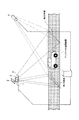
- FIG. 1 is a diagram showing a configuration of an ETC system including a vehicle detection system according to a first embodiment of the present invention.
- the ETC system includes a laser sensor 1 (emission unit), a reflection plate 2 (reflection unit), a lane server 3, and an antenna 4.
- a combination of the laser sensor 1, the reflector 2, and the lane server 3 constitutes a vehicle detection system that detects vehicle entry and exit from the communication range (predetermined area) of the antenna 4.
- the laser sensor 1 emits a laser (beam) directed radially outward of the central axis O over the circumferential direction of the central axis O. Specifically, the laser sensor 1 changes the laser emission direction toward the radially outer side of the central axis O around the central axis O over time. Further, the laser sensor 1 receives the reflected wave of the emitted laser, and calculates the distance from the laser sensor 1 to the obstacle (vehicle, passage, etc.) from the delay time from the emission of the laser to the reception of the reflected wave. .
- the laser sensor 1 is provided directly above the rear end of the communication range of the antenna 4 in the vehicle traveling direction so that the central axis O is parallel to the vehicle traveling direction. Thereby, a part of the laser emitted from the laser sensor 1 is irradiated on the first straight line which is a straight line corresponding to the rear end (entrance side) in the vehicle traveling direction in the communication range of the antenna 4.
- the reflector 2 reflects the laser emitted from the laser sensor 1.
- the reflector 2 reflects a part of the laser emitted from the laser sensor 1 so that the laser corresponds to a straight line corresponding to the front (exit side) end in the vehicle traveling direction in the communication range (predetermined region) of the antenna 4. It is provided so as to be irradiated on the second straight line. That is, the reflecting plate 2 reflects a beam that is not irradiated on the first straight line of the laser emitted from the laser sensor 1 so that it is irradiated on the second straight line.
- the lane server 3 receives scan data indicating the distance to the obstacle in the emission direction of each laser from the laser sensor 1, and detects entry and exit of the vehicle into the communication range of the antenna 4 using the scan data. To do.
- the lane server 3 detects the entry of the vehicle into the communication range of the antenna 4, the antenna 4 starts communication with the vehicle, and the lane server 3 causes the vehicle to leave the communication range of the antenna 4. If detected, the communication with the vehicle is terminated.
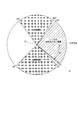
- FIG. 2 is a diagram showing a laser emission range of the laser sensor 1 according to the first embodiment of the present invention.
- the circumferential direction of 0 ° to 270 ° of the central axis O is a laser emission range toward the radially outer side of the central axis O. That is, the laser beam is not emitted in the circumferential direction 270 ° to 360 ° (0 °) of the central axis O.
- the laser sensor 1 is installed such that the direction of the central axis O in the circumferential direction 0 ° is 40 ° lower than the horizontal direction perpendicular to the vehicle traveling direction.
- the laser beam emitted from the emission range R1 in the circumferential direction 5 ° to 95 ° of the central axis O is irradiated onto the first straight line.
- the reflection plate 2 is installed in the upward direction of the laser sensor 1.
- the laser emitted from the emission range R2 in the circumferential direction 194 ° to 266 ° of the central axis O is irradiated onto the second straight line via the reflector 2.
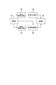
- FIG. 3 is a schematic block diagram showing the configuration of the lane server 3 according to the first embodiment.
- the lane server 3 includes a reception unit 31, a first vehicle determination unit 32, a second vehicle determination unit 33, an entry determination unit 34, an exit determination unit 35, and a communication unit 36.
- the receiving unit 31 receives scan data from the laser sensor 1.
- the first vehicle determination unit 32 determines whether there is a vehicle on the first straight line.
- the second vehicle determination unit 33 determines whether there is a vehicle on the second straight line.
- the entry determination unit 34 determines whether a vehicle has entered the communication range of the antenna 4.
- the leaving determination unit 35 determines whether or not the vehicle has left the communication range of the antenna 4.
- the communication unit 36 communicates with the vehicle via the antenna 4 based on the entry / exit of the vehicle with respect to the communication range.
- the first vehicle determination unit 32 reads the distance corresponding to each emission direction in the emission range R1 from the scan data received by the reception unit 31, and uses the distance to determine the distance between the laser sensor 1 and the first straight line. It is determined whether or not there is a vehicle. Specifically, the first vehicle determination unit 32 determines that the laser sensor 1 and the first straight line when the distance corresponding to each emission direction within the emission range R1 indicates a predetermined threshold value or less. It is determined that there is a vehicle between. As the threshold value, for example, a length obtained by subtracting 1 meter from the distance from the laser sensor 1 to the first straight line may be used.
- the entry determination unit 34 determines whether the vehicle has entered the communication range of the antenna 4 based on the previous determination result and the current determination result by the first vehicle determination unit 32. Specifically, the first vehicle determination unit 32 determines that there is no vehicle between the laser sensor 1 and the first straight line in the previous determination, and the laser sensor 1 and the first straight line in the current determination. When it is determined that there is a vehicle between the two, the entry determination unit 34 determines that the vehicle has entered the communication range of the antenna 4. In this process, for example, the previous determination result by the first vehicle determination unit 32 is recorded in the internal memory of the entry determination unit 34, and the determination result stored in the internal memory is compared with the current determination result. Can be done. That is, the entry determination unit determines that the vehicle has entered the communication range of the antenna 4 when the vehicle transitions from the state in which no vehicle exists between the laser sensor 1 and the first straight line to the state in which the vehicle exists.
- the second vehicle determination unit 33 reads distances corresponding to the respective emission directions in the emission range R2 from the scan data received by the reception unit 31, and uses the distances between the laser sensor 1 and the second straight line. It is determined whether or not there is a vehicle. Specifically, the second vehicle determination unit 33 determines that the laser sensor 1 and the second straight line when the distance corresponding to each emission direction in the emission range R2 indicates a predetermined threshold value or less. It is determined that there is a vehicle between.
- the threshold value for example, a length obtained by subtracting 1 meter from a length obtained by adding a distance from the reflecting plate 2 to the second straight line to a distance from the laser sensor 1 to the reflecting plate 2 may be used.
- the exit determination unit 35 determines whether or not the vehicle has entered the communication range of the antenna 4 based on the previous determination result and the current determination result by the second vehicle determination unit 33. Specifically, the second vehicle determination unit 33 determines that there is no vehicle between the laser sensor 1 and the second straight line in the previous determination, and the laser sensor 1 and the second straight line in the current determination. When it is determined that there is a vehicle between and the exit determination unit 35 determines that the vehicle has exited the communication range of the antenna 4. That is, it is determined that the vehicle has left the communication range of the antenna 4 when a transition is made from the state in which no vehicle exists between the laser sensor 1 and the second straight line to the state in which the vehicle exists.
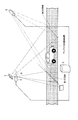
- FIG. 4 is a diagram illustrating a case where two adjacent vehicles A and B pass on the second straight line.
- the second vehicle determination unit 33 determines that the vehicle exists between the laser sensor 1 and the second straight line in both the previous determination and the current determination. Then it may be determined. Specifically, in the previous determination, as shown in FIG. 4A, it is determined that the preceding vehicle A exists between the laser sensor 1 and the second straight line, and in this determination, FIG. As shown in B), there is a case where it is determined that the following vehicle B exists between the laser sensor 1 and the second straight line.
- the distance corresponding to the emission direction in the emission range R2 in the scan data previously received by the reception unit 31, and the emission direction in the emission range R2 in the scan data received by the reception unit 31 this time.
- the distance corresponding to is a different value. Therefore, when the exit determination unit 35 determines that there is a vehicle between the laser sensor 1 and the second straight line in both the previous determination and the current determination, the exit determination unit 35 emits the scan data previously received by the reception unit 31.
- the exit determination unit 35 can determine the exit of each vehicle even when two adjacent vehicles pass on the second straight line.
- the communication unit 36 performs communication processing according to the following procedure.
- the communication unit 36 starts communication processing with the vehicle via the antenna 4 when the entry determination unit 34 determines that the vehicle has entered, and communicates until the exit determination unit 35 determines that the vehicle has exited. I do.
- the communication unit 36 determines that the vehicle is a normal ETC vehicle when the communication ends normally before the departure determination unit 35 determines that the vehicle has left. Further, when the communication does not end normally before the exit determination unit 35 determines that the vehicle has exited, the communication unit 36 determines that the vehicle is an abnormal ETC vehicle. Moreover, when the communication unit 36 cannot obtain a response from the vehicle before the departure determining unit 35 determines that the vehicle has left, the communication unit 36 determines that the vehicle is a non-ETC vehicle.
- the vehicle detection system can irradiate the beam on the entrance side and the exit side of the communication range of the antenna 4 with one laser sensor 1. Therefore, it is possible to detect the entry and exit of the vehicle with respect to a predetermined area on the passage by one laser sensor 1.
- MTBF can be lengthened and installation cost can be reduced.
- the laser sensor 1 is provided directly above the rear end of the communication range of the antenna 4 in the vehicle traveling direction so that the central axis O is parallel to the vehicle traveling direction.
- the incident angle with respect to the path of the laser irradiated onto the first straight line becomes a right angle. Accordingly, the lane server 3 can accurately determine whether or not the vehicle exists on the first straight line regardless of the height of the vehicle.
- the laser sensor 1 is provided immediately above the first straight line
- the present invention is not limited to this.
- the laser sensor 1 may be provided immediately above the second straight line so that the central axis O is parallel to the vehicle traveling direction. In this case, a part of the laser emitted from the laser sensor 1 is irradiated on the second straight line. Therefore, the reflecting plate 2 needs to be provided so that the laser is irradiated on the second straight line by reflecting a part of the laser emitted from the laser sensor 1.
- the present invention is not limited to this, and two or more reflectors may be provided.
- the laser sensor 1 is provided immediately above the passage so that the central axis O is in the vertical direction
- one reflector 2 irradiates a part of the laser emitted from the laser sensor 1 onto the first straight line.
- the other reflector 2 may be provided such that a part of the laser emitted from the laser sensor 1 is irradiated on the second straight line.
- the laser sensor 1 measures the distance to the obstacle and the lane server 3 determines the presence / absence of the vehicle based on the distance is described, but the present invention is not limited to this.
- the laser sensor 1 does not have a function of measuring the distance to the obstacle, outputs a time difference from when the laser is emitted until the reflected wave is received, and the lane server 3 determines whether the vehicle is present based on the time difference. May be determined.
- this embodiment demonstrated the case where the laser sensor 1 was used as an emitting part, it is not restricted to this, For example, you may radiate
- the case where the laser emitted from the emission range R1 is irradiated on the first straight line and the laser emitted from the emission range R2 is irradiated on the second straight line has been described.
- the present invention is not limited to this, and laser beams emitted from other emission ranges may be irradiated on the first straight line and the second straight line.
- the vehicle detection system according to the second embodiment has a function of determining whether the vehicle is moving forward or backward in addition to the function of the vehicle detection system according to the first embodiment.
- FIG. 5 is a diagram showing a configuration of an ETC system including a vehicle detection system according to the second embodiment of the present invention.
- the vehicle detection system according to the second embodiment includes a reflector 5 in addition to the configuration of the vehicle detection system according to the first embodiment, and the processing of the lane server 3 is different.
- the reflector 5 reflects the laser emitted from the laser sensor 1.
- the reflecting plate 5 reflects a part of the laser emitted by the laser sensor 1 so that the laser is a straight line in the vicinity of the first straight line (reference straight line) in the vehicle traveling direction and is a straight line that crosses the passage. It is provided so that the beam is irradiated on the third straight line.
- FIG. 6 is a diagram showing a laser emission range by the laser sensor 1 according to the second embodiment of the present invention.
- the circumferential direction of 0 ° to 270 ° of the central axis O is a laser emission range toward the radially outer side of the central axis O. That is, the laser beam is not emitted in the circumferential direction 270 ° to 360 ° (0 °) of the central axis O.
- the laser sensor 1 is installed so that the direction of the central axis O in the circumferential direction 0 ° is 40 ° downward from the horizontal direction.
- the laser beam emitted from the emission range R1 in the circumferential direction 5 ° to 95 ° of the central axis O is irradiated onto the first straight line.
- the reflection plate 2 is installed in the upward direction of the laser sensor 1.
- the laser emitted from the emission range R2 in the circumferential direction 194 ° to 266 ° of the central axis O is irradiated onto the second straight line via the reflector 2.
- the reflecting plate 5 is installed on the side of the laser sensor 1.
- the laser beam emitted from the emission range R3 in the circumferential direction 120 ° to 140 ° of the central axis O is irradiated onto the third straight line via the reflecting plate 5.
- FIG. 7 is a schematic block diagram showing the configuration of the lane server 3 according to the second embodiment.
- the lane server 3 includes a third vehicle determination unit 37 and a traveling direction determination unit 38 in addition to the lane server 3 according to the first embodiment.
- the third vehicle determination unit 37 reads distances corresponding to the respective emission directions in the emission range R3 from the scan data received by the reception unit 31, and uses the distances between the laser sensor 1 and the third straight line. It is determined whether or not there is a vehicle. Specifically, the third vehicle determination unit 37 determines that the laser sensor 1 and the third straight line when the distance corresponding to each emission direction in the emission range R3 indicates a predetermined threshold value or less. It is determined that there is a vehicle between.
- the traveling direction determination unit 38 determines whether the vehicle has moved forward or backward using the determination results of the first vehicle determination unit 32 and the third vehicle determination unit 37.
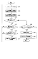
- FIG. 8 is a flowchart showing an operation in which the lane server 3 determines the traveling direction of the vehicle.
- the receiving unit 31 periodically receives scan data from the laser sensor 1 (step S1).
- the first vehicle determination unit 32 reads the distance corresponding to each emission direction in the emission range R1 from the received scan data, and uses the distance to read the laser sensor 1 and the first data. It is determined whether or not a vehicle exists between the first straight line (step S2).
- the third vehicle determination unit 37 reads distances corresponding to the respective emission directions in the emission range R3 from the received scan data, and uses the distances between the laser sensor 1 and the third straight line. It is determined whether or not a vehicle exists (step S3).
- the traveling direction determination unit 38 stores the current determination result (hereinafter referred to as the current determination result) by the first vehicle determination unit 32 and the second vehicle determination unit 33 and the internal memory in step S5 described later.
- the previous determination result (hereinafter referred to as the previous determination result) by the first vehicle determination unit 32 and the second vehicle determination unit 33, it is determined whether the vehicle has advanced or retreated (step S4). ).
- the traveling direction determination unit 38 determines that the vehicle has moved forward.
- the traveling direction determination unit 38 determines that the vehicle has moved backward.
- the traveling direction determination unit 38 determines that the vehicle has moved forward.
- the traveling direction determination unit 38 determines that the vehicle has moved backward.
- the traveling direction determination unit 38 determines that the vehicle has advanced.
- the traveling direction determination unit 38 determines that the vehicle has moved backward.
- the traveling direction determination unit 38 determines that the vehicle has advanced.
- the traveling direction determination unit 38 determines that the vehicle has moved backward.
- the traveling direction determination unit 38 determines the traveling direction of the vehicle by the process of step S4, the current determination result by the first vehicle determination unit 32 and the second vehicle determination unit 33 is stored in the internal memory as the previous determination result. (Step S5).
- the lane server 3 can determine at any time whether the vehicle has moved forward or backward.
- FIG. 9 is a first diagram showing the positional relationship between the vehicle detection system and the vehicle in time series.
- FIG. 10 is a second diagram showing the positional relationship between the vehicle detection system and the vehicle in time series.
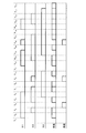
- FIG. 11 is a time chart showing the determination result of the presence / absence of the vehicle and the determination result of the traveling direction of the vehicle by the lane server 3.
- the traveling direction determination unit 38 determines that the vehicle has advanced.
- the traveling direction determination unit 38 determines that the vehicle has advanced.
- the traveling direction determination unit 38 determines that the vehicle has moved backward.
- the traveling direction determination unit 38 determines that the vehicle has advanced.
- the traveling direction determination unit 38 does not determine whether the vehicle has moved forward or backward.
- the traveling direction determination unit 38 determines that the vehicle has advanced.
- the traveling direction determination unit 38 determines that the vehicle has advanced.
- the traveling direction determination unit 38 determines that the vehicle has advanced.
- the traveling direction determination unit 38 determines that the vehicle has advanced.
- the traveling direction determination unit 38 does not determine whether the vehicle has moved forward or backward.
- the traveling direction determination unit 38 determines that the vehicle has advanced.
- the traveling direction determination unit 38 does not determine whether the vehicle has moved forward or backward.
- the traveling direction determination unit 38 determines that the vehicle has advanced.
- the traveling direction determination unit 38 determines that the vehicle has moved backward.
- the traveling direction determination unit 38 determines that the vehicle has advanced.
- the traveling direction determination unit 38 determines that the vehicle has advanced.
- the traveling direction determination unit 38 determines that the vehicle has advanced.
- the traveling direction determination unit 38 determines that the vehicle has advanced.
- the traveling direction determination unit 38 determines that the vehicle has advanced.
- the traveling direction determination unit 38 does not determine whether the vehicle has moved forward or backward.
- the vehicle detection system uses the single laser sensor 1 to detect the entry and exit of the vehicle with respect to a predetermined area on the passage, and whether the vehicle on the passage has advanced.
- a process for determining whether the vehicle has moved backward can be executed.
- path can be performed by the method similar to 1st Embodiment.
- the reflecting plate 5 reflects a part of the laser emitted from the laser sensor 1 so that the laser is a straight line in the vicinity of the first straight line in the vehicle traveling direction and passes through the path.
- the beam is provided so as to be irradiated on the third straight line that is a transverse line
- the present invention is not limited to this.
- the reflecting plate 5 reflects a part of the laser emitted from the laser sensor 1 so that the laser is a straight line near the rear in the vehicle traveling direction of the first straight line and crosses the passage. You may provide so that a beam may be irradiated.
- the advancing direction determination unit 38 determines “retracted” in the pattern determined as “advanced” in the present embodiment, and determined “advanced” in the pattern determined as “retracted” in the present embodiment. Will be.
- the reflecting plate 5 reflects a part of the laser emitted from the laser sensor 1 so that the laser is a straight line near the front of the second straight line (reference straight line) in the vehicle traveling direction. You may provide so that a beam may be irradiated on the crossing straight line.
- the traveling direction determination unit 38 determines whether the vehicle has moved forward or backward using the determination result of the second vehicle determination unit 33 and the determination result of the third vehicle determination unit 37.
- the reflecting plate 5 reflects a part of the laser emitted by the laser sensor 1 so that the laser is a straight line near the rear of the second straight line (reference straight line) in the vehicle traveling direction and passes through the path. You may provide so that a beam may be irradiated on the crossing straight line.
- the vehicle detection system according to the third embodiment has a function of counting the number of vehicle axes in addition to the function of the vehicle detection system according to the first embodiment.
- FIG. 12 is a diagram showing a configuration of an ETC system including a vehicle detection system according to the third embodiment of the present invention.
- the vehicle detection system according to the third embodiment includes a reflector 6 in addition to the configuration of the vehicle detection system according to the first embodiment, and the processing of the lane server 3 is different.
- the reflector 6 reflects the laser emitted from the laser sensor 1.
- the reflecting plate 6 reflects a part of the laser emitted from the laser sensor 1 so that the laser is emitted from one end of the passage toward the width direction of the passage just above the first straight line. Provided.
- FIG. 13 is a diagram showing a laser emission range of the laser sensor 1 according to the third embodiment of the present invention.
- the circumferential direction of 0 ° to 270 ° of the central axis O is a laser emission range toward the radially outer side of the central axis O. That is, the laser beam is not emitted in the circumferential direction 270 ° to 360 ° (0 °) of the central axis O.
- the laser sensor 1 is installed so that the direction of the central axis O in the circumferential direction 0 ° is 40 ° downward from the horizontal direction.
- the laser beam emitted from the emission range R1 in the circumferential direction 5 ° to 95 ° of the central axis O is irradiated onto the first straight line.
- the reflection plate 2 is installed in the upward direction of the laser sensor 1.
- the laser emitted from the emission range R2 in the circumferential direction 194 ° to 266 ° of the central axis O is irradiated onto the second straight line via the reflector 2.
- the reflecting plate 6 is installed at a position on the first straight line and on the side of the passage.
- the laser emitted from the emission range R4 in the circumferential direction 0 ° to 1 ° of the central axis O is irradiated from the one end of the passage toward the width direction of the passage via the reflection plate 6.
- FIG. 14 is a schematic block diagram showing the configuration of the lane server 3 according to the third embodiment.
- the lane server 3 includes an axle determination unit 39 and an axle counting unit 40 in addition to the lane server 3 according to the first embodiment.
- the axle determination unit 39 reads a distance corresponding to the emission direction in the emission range R4 from the scan data received by the reception unit 31, and uses the distance to determine whether an axle is present on the first straight line. To do. Specifically, the axle determination unit 39 determines that there is an axle on the first straight line when there is a distance that is equal to or less than a predetermined threshold in the distance corresponding to each emission direction in the emission range R4. .
- the axle counting unit 40 counts the number of axles of the vehicle using the determination result of the axle determination unit 39 and the determination result of the first vehicle determination unit 32.
- FIG. 15 is a flowchart showing an operation in which the lane server 3 determines the number of axles.
- the receiving unit 31 periodically receives scan data from the laser sensor 1 (step S11).
- the first vehicle determination unit 32 reads the distance corresponding to each emission direction in the emission range R1 from the received scan data, and uses the distance to read the laser sensor 1 and the first data. It is determined whether or not there is a vehicle between the first straight line (step S12).
- the axle determination unit 39 reads distances corresponding to the respective emission directions in the emission range R4 from the received scan data, and uses the distances to determine whether an axle is present immediately above the first straight line. Determination is made (step S13).
- the axle counting unit 40 determines whether or not the determination result by the first vehicle determination unit 32 indicates that a vehicle exists between the laser sensor 1 and the first straight line (step S14). When the determination result by the first vehicle determination unit 32 indicates that a vehicle is present between the laser sensor 1 and the first straight line (step S14: YES), the axle counting unit 40 is determined by the axle determination unit 39. It is determined whether or not the determination result indicates that an axle is present immediately above the first straight line (step S15).
- step S15 When the determination result by the axle determination unit 39 indicates that an axle is present immediately above the first straight line (step S15: YES), the axle counting unit 40 determines that the previous determination result by the axle determination unit 39 is the first It is determined whether or not an axle is present immediately above the straight line (step S16). When the previous determination result by the axle determination unit 39 indicates that no axle is present immediately above the first straight line (step S16: NO), the axle counting unit 40 adds 1 to the number of axles stored in the internal memory. (Step S17). In the initial state, the number of axles stored in the internal memory is zero.
- step S15 When the current determination result by the axle determination unit 39 indicates that no axle is present immediately above the first straight line (step S15: NO), the previous determination result by the axle determination unit 39 is immediately above the first straight line. Indicates that an axle is present (step S16: NO), or if 1 is added to the number of axles in step S17, the process returns to step S11 and waits for reception of the next scan data.
- step S14 when the determination result by the first vehicle determination unit 32 indicates that there is no vehicle between the laser sensor 1 and the first straight line (step S14: NO), the axle counting unit 40 is Then, it is determined whether or not the number of axles stored in the internal memory is 1 or more (step S18).
- step S18: YES the axle counting unit 40 determines the number of axles stored in the internal memory as the number of axles of the vehicle (step S19), and the number of axles concerned. Is output to a predetermined output destination, and then the number of axles is rewritten to 0 (step S20).
- step S18: NO the axle counting unit 40 determines that the vehicle does not pass on the first straight line, and ends the process.
- the vehicle detection system uses the single laser sensor 1 to detect the entry and exit of a vehicle from a predetermined area on the passage, and the number of axles of the vehicle on the passage.
- a counting process can be executed.
- path can be performed by the method similar to 1st Embodiment.
- the reflecting plate 6 reflects a part of the laser emitted from the laser sensor 1 so that the laser is directly above the first straight line from one end of the passage in the width direction of the passage. Although the case where it irradiates toward was demonstrated, it is not restricted to this.
- the reflecting plate 6 reflects a part of the laser emitted from the laser sensor 1 so that the laser is emitted from one end of the passage toward the width direction of the passage just above the second straight line.
- the axle counting unit 40 counts the number of axles of the vehicle using the determination result of the axle determination unit 39 and the determination result of the second vehicle determination unit 33.
- the laser sensor 1 is preferably provided above the passage. However, as long as the beam is irradiated on the first straight line and the second straight line, the laser sensor 1 is provided at any position near the passage. Also, the effect of the present invention can be obtained.
- the lane server 3 has a computer system therein.
- the operation of each processing unit described above is stored in a computer-readable recording medium in the form of a program, and the above processing is performed by the computer reading and executing this program.
- the computer-readable recording medium means a magnetic disk, a magneto-optical disk, a CD-ROM, a DVD-ROM, a semiconductor memory, or the like.
- the computer program may be distributed to the computer via a communication line, and the computer that has received the distribution may execute the program.
- the program may be for realizing a part of the functions described above. Furthermore, what can implement
- the present invention relates to a vehicle detection system that detects entry and exit of a vehicle with respect to a predetermined area on a passage.
- the mean time between failures (MTBF) can be made longer than before.
Landscapes
- Physics & Mathematics (AREA)
- General Physics & Mathematics (AREA)
- Traffic Control Systems (AREA)
- Devices For Checking Fares Or Tickets At Control Points (AREA)
Abstract
この車両検知システムのレーザセンサ(1)は、中心軸(O)の径方向外側に向かうレーザを中心軸(O)の周方向に亘って出射する。反射板(2)は、アンテナ(4)の通信範囲における車両進行方向後方の端に相当する直線である第1の直線上、及びアンテナ(4)の通信範囲における車両進行方向前方の端に相当する直線である第2の直線上にレーザが照射されるように、レーザセンサ(1)が出射するレーザの一部を反射させる。
Description
本発明は、通路上の所定の領域に対する車両の進入及び退出を検知する車両検知システム、及び車両検知方法に関する。
本願は、2010年12月3日に日本に出願された特願2010-270517号について優先権を主張し、その内容をここに援用する。
本願は、2010年12月3日に日本に出願された特願2010-270517号について優先権を主張し、その内容をここに援用する。
高速道路の通行料の課金を行うETC(Electronic Toll Collection)システムが普及している。ETCシステムは、車両検知システムにより車両の進入を検知して路側に設けられたアンテナによる通信を行うことで、車両に対する課金処理を実行する。車両検知システムは、アンテナの通信範囲の入口と出口とに配置された2組の車両検知器によって構成され、入口側の車両検知器が車両を検知したときにアンテナの通信範囲内に車両が進入したと判定し、出口側の車両検知器が車両を検知したときにアンテナの通信範囲外へ車両が退出したと判定する。
従来の車両検知器は、車線の両側に設置される一対の光センサから構成され、光センサ対の間の空間が通光状態であるか遮光状態であるかを判定する(例えば、特許文献1参照)。そして、車両検知器は、光センサ対が通光状態である場合に、光センサ対の間に車両が存在すると判定し、遮光状態である場合に、光センサ対の間に車両が存在しないと判定する。
しかしながら、2組の車両検知器からなる車両検知システムは、MTBF(Mean Time Between Failure:平均故障間隔)が短い。
具体的には、一方の車両検知器が正常に動作していたとしても、他方の車両検知器が故障した場合、車両の進入・退出の検知処理を行うことができなくなる。すなわち、2組の車両検知器からなる車両検知システムのMTBFは、1組の車両検知器のMTBFより短くなってしまう。
また、従来の車両検知方法を実行するには、車両検知器を2組用いるため、機器の設置コストが高い。
具体的には、一方の車両検知器が正常に動作していたとしても、他方の車両検知器が故障した場合、車両の進入・退出の検知処理を行うことができなくなる。すなわち、2組の車両検知器からなる車両検知システムのMTBFは、1組の車両検知器のMTBFより短くなってしまう。
また、従来の車両検知方法を実行するには、車両検知器を2組用いるため、機器の設置コストが高い。
本発明は上記の課題を解決するためになされたものであり、通路上の所定の領域に対する車両の進入及び退出を検知する車両検知システムであって、中心軸の径方向外側に向かうビームを当該中心軸の周方向に亘って出射する出射部と、前記所定の領域における車両進行方向後方の端に相当する直線である第1の直線上、及び前記所定の領域における車両進行方向前方の端に相当する直線である第2の直線上に前記ビームが照射されるように、前記ビームの少なくとも一部を反射させる反射部とを備える。
また、本発明においては、前記出射部が出射したビームの反射波を用いて、前記出射部と前記第1の直線との間に車両が存在するか否かを判定し、車両が存在しない状態から車両が存在する状態に遷移したときに、当該車両が前記所定の領域に進入したと判定する進入判定部と、前記出射部が出射したビームの反射波を用いて、前記出射部と前記第2の直線との間に前記車両が存在するか否かを判定し、車両が存在しない状態から車両が存在する状態に遷移したときに、当該車両が前記所定の領域から退出したと判定する退出判定部と、を備えてもよい。
また、本発明においては、前記出射部は、前記中心軸が前記車両進行方向と平行をなすように前記第1の直線の直上に設けられ、前記反射部は、前記出射部が出射するビームのうち前記第1の直線上に照射されないビームを、前記第2の直線上に照射されるように反射させてもよい。
また、本発明においては、前記反射部は、前記第1の直線または前記第2の直線である基準直線に近傍の直線であって前記通路を横断する直線である第3の直線上に前記ビームが照射されるように、前記ビームの少なくとも一部を反射させてもよい。
また、本発明においては、前記出射部と前記基準直線との間に車両が存在するか否か、及び前記出射部と前記第3の直線との間に車両が存在するか否かを判定する車両判定部と、前記車両判定部による今回の判定結果と前回の判定結果とを比較することで車両の進行方向を判定する進行方向判定部とを備えてもよい。
また、本発明においては、前記反射部は、前記通路の一端から前記通路の幅方向に向かって前記ビームが照射されるように、前記ビームの少なくとも一部を反射させてもよい。
また、本発明においては、前記出射部が出射したビームのうち、前記反射部によって前記通路の一端から前記通路の幅方向に照射されたビームの反射波を用いて、車両の車軸数を計数する車軸計数部を備えてもよい。
また、本発明は、上記車両検知システムの出射部が出射したビームの反射波を用いて、前記出射部と前記第1の直線との間に車両が存在するか否かを判定し、車両が存在しない状態から車両が存在する状態に遷移したときに、当該車両が前記所定の領域に進入したと判定するステップと、前記出射部が出射したビームの反射波を用いて、前記出射部と前記第2の直線との間に前記車両が存在するか否かを判定し、車両が存在しない状態から車両が存在する状態に遷移したときに、当該車両が前記所定の領域から退出したと判定するステップとを含む車両検知方法である。
本発明によれば、車両検知システムは、1つの出射部と反射部とを備えることで、1台で第1の直線上、及び第2の直線上にビームを照射することができる。そのため、1台の車両検知器によって通路上の所定の領域に対する車両の進入及び退出を検知する。これにより、2組の車両検知器からなる車両検知システムと比較してMTBFを長くすることができる。また、車両検知器の台数を1台にすることができるため、2組の車両検知器からなる車両検知システムと比較して設置コストを下げることができる。
(第1の実施形態)
以下、図面を参照しながら本発明の第1の実施形態について詳しく説明する。
図1は、本発明の第1の実施形態による車両検知システムを備えるETCシステムの構成を示す図である。
ETCシステムは、レーザセンサ1(出射部)、反射板2(反射部)、車線サーバ3、アンテナ4を備える。なお、レーザセンサ1、反射板2、車線サーバ3の組み合わせによって、アンテナ4の通信範囲(所定の領域)に対する車両の進入及び退出を検知する車両検知システムが構成される。
以下、図面を参照しながら本発明の第1の実施形態について詳しく説明する。
図1は、本発明の第1の実施形態による車両検知システムを備えるETCシステムの構成を示す図である。
ETCシステムは、レーザセンサ1(出射部)、反射板2(反射部)、車線サーバ3、アンテナ4を備える。なお、レーザセンサ1、反射板2、車線サーバ3の組み合わせによって、アンテナ4の通信範囲(所定の領域)に対する車両の進入及び退出を検知する車両検知システムが構成される。
レーザセンサ1は、中心軸Oの径方向外側に向かうレーザ(ビーム)を、当該中心軸Oの周方向に亘って出射する。具体的には、レーザセンサ1は、中心軸Oの径方向外側に向かうレーザの出射方向を当該中心軸O回りに経時的に変化させる。また、レーザセンサ1は、出射したレーザの反射波を受信し、レーザの出射からから反射波の受信までの遅延時間から、レーザセンサ1から障害物(車両、通路など)までの距離を算出する。
レーザセンサ1は、中心軸Oが車両進行方向と平行をなすように、アンテナ4の通信範囲の車両進行方向後方の端の直上に設けられる。これにより、レーザセンサ1が出射するレーザの一部は、アンテナ4の通信範囲における車両進行方向後方の端(入口側)に相当する直線である第1の直線上に照射される。
反射板2は、レーザセンサ1が出射するレーザを反射させる。反射板2は、レーザセンサ1が出射するレーザの一部を反射させることで、当該レーザが、アンテナ4の通信範囲(所定の領域)における車両進行方向前方(出口側)の端に相当する直線である第2の直線上に照射されるように設けられる。すなわち、反射板2は、レーザセンサ1が出射するレーザのうち第1の直線上に照射されないビームを、第2の直線上に照射されるように反射させる。
車線サーバ3は、レーザセンサ1から、各レーザの出射方向における障害物までの距離を示すスキャンデータを受信し、当該スキャンデータを用いて、アンテナ4の通信範囲への車両の進入及び退出を検知する。
アンテナ4は、車線サーバ3が、アンテナ4の通信範囲への車両の進入を検知した場合に、当該車両との通信を開始し、車線サーバ3が、アンテナ4の通信範囲からの車両の退出を検知した場合に、当該車両との通信を終了する。
アンテナ4は、車線サーバ3が、アンテナ4の通信範囲への車両の進入を検知した場合に、当該車両との通信を開始し、車線サーバ3が、アンテナ4の通信範囲からの車両の退出を検知した場合に、当該車両との通信を終了する。
図2は、本発明の第1の実施形態によるレーザセンサ1によるレーザの出射範囲を示す図である。
本実施形態で用いるレーザセンサ1は、中心軸Oの周方向0°~270°を、中心軸Oの径方向外側に向かうレーザの出射範囲とする。すなわち、中心軸Oの周方向270°~360°(0°)の方向にはレーザが出射されない。
本実施形態においてレーザセンサ1は、中心軸Oの周方向0°の方向が車両進行方向に直行する水平方向より40°下向きとなるように設置される。これにより、中心軸Oの周方向5°~95°の出射範囲R1から出射されたレーザが、第1の直線上に照射されることとなる。
また、本実施形態において反射板2は、レーザセンサ1の上方向に設置される。これにより、中心軸Oの周方向194°~266°の出射範囲R2から出射されたレーザは、反射板2を介して第2の直線上に照射されることとなる。
本実施形態で用いるレーザセンサ1は、中心軸Oの周方向0°~270°を、中心軸Oの径方向外側に向かうレーザの出射範囲とする。すなわち、中心軸Oの周方向270°~360°(0°)の方向にはレーザが出射されない。
本実施形態においてレーザセンサ1は、中心軸Oの周方向0°の方向が車両進行方向に直行する水平方向より40°下向きとなるように設置される。これにより、中心軸Oの周方向5°~95°の出射範囲R1から出射されたレーザが、第1の直線上に照射されることとなる。
また、本実施形態において反射板2は、レーザセンサ1の上方向に設置される。これにより、中心軸Oの周方向194°~266°の出射範囲R2から出射されたレーザは、反射板2を介して第2の直線上に照射されることとなる。
次に、車線サーバ3の構成を説明する。
図3は、第1の実施形態による車線サーバ3の構成を示す概略ブロック図である。
車線サーバ3は、受信部31、第1の車両判定部32、第2の車両判定部33、進入判定部34、退出判定部35、通信部36を備える。
受信部31は、レーザセンサ1からスキャンデータを受信する。
第1の車両判定部32は、第1の直線上に車両が存在するか否かを判定する。
第2の車両判定部33は、第2の直線上に車両が存在するか否かを判定する。
進入判定部34は、アンテナ4の通信範囲に車両が進入したか否かを判定する。
退出判定部35は、アンテナ4の通信範囲から車両が退出したか否かを判定する。
通信部36は、通信範囲に対する車両の進入・退出に基づいてアンテナ4を介して車両と通信を行う。
図3は、第1の実施形態による車線サーバ3の構成を示す概略ブロック図である。
車線サーバ3は、受信部31、第1の車両判定部32、第2の車両判定部33、進入判定部34、退出判定部35、通信部36を備える。
受信部31は、レーザセンサ1からスキャンデータを受信する。
第1の車両判定部32は、第1の直線上に車両が存在するか否かを判定する。
第2の車両判定部33は、第2の直線上に車両が存在するか否かを判定する。
進入判定部34は、アンテナ4の通信範囲に車両が進入したか否かを判定する。
退出判定部35は、アンテナ4の通信範囲から車両が退出したか否かを判定する。
通信部36は、通信範囲に対する車両の進入・退出に基づいてアンテナ4を介して車両と通信を行う。
ここで、車両がアンテナ4の通信範囲に進入したか否かを判定する方法を説明する。
第1の車両判定部32は、受信部31が受信したスキャンデータから出射範囲R1内の各出射方向に対応する距離を読み出し、当該距離を用いて、レーザセンサ1と第1の直線との間に車両が存在するか否かを判定する。具体的には、第1の車両判定部32は、出射範囲R1内の各出射方向に対応する距離の中に所定の閾値以下を示すものがある場合に、レーザセンサ1と第1の直線との間に車両が存在すると判定する。閾値としては、例えば、レーザセンサ1から第1の直線までの距離から1メートルを減じた長さなどを用いると良い。
第1の車両判定部32は、受信部31が受信したスキャンデータから出射範囲R1内の各出射方向に対応する距離を読み出し、当該距離を用いて、レーザセンサ1と第1の直線との間に車両が存在するか否かを判定する。具体的には、第1の車両判定部32は、出射範囲R1内の各出射方向に対応する距離の中に所定の閾値以下を示すものがある場合に、レーザセンサ1と第1の直線との間に車両が存在すると判定する。閾値としては、例えば、レーザセンサ1から第1の直線までの距離から1メートルを減じた長さなどを用いると良い。
次に、進入判定部34は、第1の車両判定部32による前回の判定結果と今回の判定結果とに基づいて車両がアンテナ4の通信範囲に進入したか否かを判定する。具体的には、第1の車両判定部32が、前回の判定においてレーザセンサ1と第1の直線との間に車両が存在しないと判定し、今回の判定においてレーザセンサ1と第1の直線との間に車両が存在すると判定した場合、進入判定部34は、当該車両がアンテナ4の通信範囲に進入したと判定する。この処理は、例えば、第1の車両判定部32による前回の判定結果を進入判定部34の内部メモリに記録しておき、内部メモリに記憶された判定結果と今回の判定結果とを比較することで行うことができる。
すなわち、進入判定部は、レーザセンサ1と第1の直線との間に車両が存在しない状態から車両が存在する状態に遷移したときに、車両がアンテナ4の通信範囲に進入したと判定する。
すなわち、進入判定部は、レーザセンサ1と第1の直線との間に車両が存在しない状態から車両が存在する状態に遷移したときに、車両がアンテナ4の通信範囲に進入したと判定する。
次に、車両がアンテナ4の通信範囲から退出したか否かを判定する方法を説明する。
第2の車両判定部33は、受信部31が受信したスキャンデータから出射範囲R2内の各出射方向に対応する距離を読み出し、当該距離を用いて、レーザセンサ1と第2の直線との間に車両が存在するか否かを判定する。具体的には、第2の車両判定部33は、出射範囲R2内の各出射方向に対応する距離の中に所定の閾値以下を示すものがある場合に、レーザセンサ1と第2の直線との間に車両が存在すると判定する。閾値としては、例えば、レーザセンサ1から反射板2までの距離に反射板2から第2の直線までの距離を加算した長さから1メートルを減じた長さなどを用いると良い。
第2の車両判定部33は、受信部31が受信したスキャンデータから出射範囲R2内の各出射方向に対応する距離を読み出し、当該距離を用いて、レーザセンサ1と第2の直線との間に車両が存在するか否かを判定する。具体的には、第2の車両判定部33は、出射範囲R2内の各出射方向に対応する距離の中に所定の閾値以下を示すものがある場合に、レーザセンサ1と第2の直線との間に車両が存在すると判定する。閾値としては、例えば、レーザセンサ1から反射板2までの距離に反射板2から第2の直線までの距離を加算した長さから1メートルを減じた長さなどを用いると良い。
次に、退出判定部35は、第2の車両判定部33による前回の判定結果と今回の判定結果とに基づいて車両がアンテナ4の通信範囲に進入したか否かを判定する。具体的には、第2の車両判定部33が、前回の判定においてレーザセンサ1と第2の直線との間に車両が存在しないと判定し、今回の判定においてレーザセンサ1と第2の直線との間に車両が存在すると判定した場合、退出判定部35は、当該車両がアンテナ4の通信範囲から退出したと判定する。すなわち、レーザセンサ1と第2の直線との間に車両が存在しない状態から車両が存在する状態に遷移したときに、当該車両がアンテナ4の通信範囲から退出したと判定する。
図4は、近接した2つの車両A、Bが第2の直線上を通過する場合を示す図である。
近接した2つの車両が第2の直線上を通過する場合、第2の車両判定部33が、前回の判定及び今回の判定で、ともにレーザセンサ1と第2の直線との間に車両が存在すると判定することがある。具体的には、前回の判定において、図4(A)に示すように、レーザセンサ1と第2の直線との間に先行の車両Aが存在すると判定され、今回の判定において、図4(B)に示すように、レーザセンサ1と第2の直線との間に後続の車両Bが存在すると判定された場合が挙げられる。つまり、前回の判定においては、レーザセンサ1と第1の直線との間に後続の車両Bが存在し、レーザセンサ1と第2の直線との間には先行の車両Aが存在すると判定され、今回の判定においては、レーザセンサ1と第1の直線との間にも、レーザセンサ1と第2の直線との間にも後続の車両Bが存在すると判定される場合である。
近接した2つの車両が第2の直線上を通過する場合、第2の車両判定部33が、前回の判定及び今回の判定で、ともにレーザセンサ1と第2の直線との間に車両が存在すると判定することがある。具体的には、前回の判定において、図4(A)に示すように、レーザセンサ1と第2の直線との間に先行の車両Aが存在すると判定され、今回の判定において、図4(B)に示すように、レーザセンサ1と第2の直線との間に後続の車両Bが存在すると判定された場合が挙げられる。つまり、前回の判定においては、レーザセンサ1と第1の直線との間に後続の車両Bが存在し、レーザセンサ1と第2の直線との間には先行の車両Aが存在すると判定され、今回の判定においては、レーザセンサ1と第1の直線との間にも、レーザセンサ1と第2の直線との間にも後続の車両Bが存在すると判定される場合である。
この場合、図4に示すように、受信部31が前回受信したスキャンデータにおける出射範囲R2内の出射方向に対応する距離と、受信部31が今回受信したスキャンデータにおける出射範囲R2内の出射方向に対応する距離とが異なる値を示すこととなる。
そのため、退出判定部35は、前回の判定及び今回の判定で、ともにレーザセンサ1と第2の直線との間に車両が存在すると判定した場合において、受信部31が前回受信したスキャンデータにおける出射範囲R2内の出射方向に対応する距離と、受信部31が今回受信したスキャンデータにおける出射範囲R2内の出射方向に対応する距離との差が所定の閾値以上であると判定した場合にも、車両がアンテナ4の通信範囲から退出したと判定する。閾値としては、例えば、0.5メートル程度の長さを用いると良い。
上記処理を実行することで、退出判定部35は、近接した2つの車両が第2の直線上を通過する場合においても、それぞれの車両の退出を判定することができる。
そのため、退出判定部35は、前回の判定及び今回の判定で、ともにレーザセンサ1と第2の直線との間に車両が存在すると判定した場合において、受信部31が前回受信したスキャンデータにおける出射範囲R2内の出射方向に対応する距離と、受信部31が今回受信したスキャンデータにおける出射範囲R2内の出射方向に対応する距離との差が所定の閾値以上であると判定した場合にも、車両がアンテナ4の通信範囲から退出したと判定する。閾値としては、例えば、0.5メートル程度の長さを用いると良い。
上記処理を実行することで、退出判定部35は、近接した2つの車両が第2の直線上を通過する場合においても、それぞれの車両の退出を判定することができる。
上記処理によって進入判定部34及び退出判定部35がアンテナ4の通信範囲に対する車両の進入・退出を判定すると、通信部36は、以下に示す手順で通信処理を行う。
通信部36は、進入判定部34によって車両が進入したと判定されたときに、アンテナ4を介して車両との通信処理を開始し、退出判定部35によって車両が退出したと判定されるまで通信を行う。なお、通信部36は、退出判定部35によって車両が退出したと判定されるまでに通信が正常に終了した場合、当該車両を正常ETC車と判定する。また、通信部36は、退出判定部35によって車両が退出したと判定されるまでに通信が正常に終了しなかった場合、当該車両を異常ETC車と判定する。また、通信部36は、退出判定部35によって車両が退出したと判定されるまでに車両からの応答を得ることができなかった場合、当該車両を非ETC車と判定する。
通信部36は、進入判定部34によって車両が進入したと判定されたときに、アンテナ4を介して車両との通信処理を開始し、退出判定部35によって車両が退出したと判定されるまで通信を行う。なお、通信部36は、退出判定部35によって車両が退出したと判定されるまでに通信が正常に終了した場合、当該車両を正常ETC車と判定する。また、通信部36は、退出判定部35によって車両が退出したと判定されるまでに通信が正常に終了しなかった場合、当該車両を異常ETC車と判定する。また、通信部36は、退出判定部35によって車両が退出したと判定されるまでに車両からの応答を得ることができなかった場合、当該車両を非ETC車と判定する。
このように、本実施形態によれば、車両検知システムは、1台のレーザセンサ1でアンテナ4の通信範囲の入口側及び出口側にビームを照射することができる。そのため、1台のレーザセンサ1によって通路上の所定の領域に対する車両の進入及び退出を検知することができる。これにより、2組の車両検知器からなる車両検知システムと比較してMTBFを長くし、かつ設置コストを下げることができる。
また、本実施形態によれば、レーザセンサ1は、中心軸Oが車両進行方向と平行をなすように、アンテナ4の通信範囲の車両進行方向後方の端の直上に設けられる。これにより、第1の直線上に照射されるレーザは、通路に対する入射角が直角となる。これにより、車線サーバ3は、車両が第1の直線上に存在するか否かを車両の高さに関わらず正確に判定することができる。
以上、図面を参照してこの発明の第1の実施形態について詳しく説明してきたが、具体的な構成は上述のものに限られることはなく、この発明の要旨を逸脱しない範囲内において様々な設計変更等をすることが可能である。
本実施形態では、レーザセンサ1の第1の直線の直上に設けられる場合を説明したが、これに限られない。例えば、レーザセンサ1は、中心軸Oが車両進行方向と平行をなすように、第2の直線の直上に設けられていても良い。この場合、レーザセンサ1が出射するレーザの一部は、第2の直線上に照射される。そのため、反射板2は、レーザセンサ1が出射するレーザの一部を反射させることで当該レーザが第2の直線上に照射されるように設けられる必要がある。
本実施形態では、レーザセンサ1の第1の直線の直上に設けられる場合を説明したが、これに限られない。例えば、レーザセンサ1は、中心軸Oが車両進行方向と平行をなすように、第2の直線の直上に設けられていても良い。この場合、レーザセンサ1が出射するレーザの一部は、第2の直線上に照射される。そのため、反射板2は、レーザセンサ1が出射するレーザの一部を反射させることで当該レーザが第2の直線上に照射されるように設けられる必要がある。
また、本実施形態では、反射板2を1つだけ備える場合を説明したが、これに限られず、2つ以上備えていても良い。例えば、レーザセンサ1が、中心軸Oが鉛直方向となるように通路の直上に設けられる場合、1つの反射板2が、レーザセンサ1が出射するレーザの一部が第1の直線上に照射されるように設けられ、もう1つの反射板2が、レーザセンサ1が出射するレーザの一部が第2の直線上に照射されるように設けられても良い。
また、本実施形態では、レーザセンサ1が障害物との距離を測定し、車線サーバ3が当該距離に基づいて車両の有無を判定する場合を説明したが、これに限られない。例えば、レーザセンサ1は、障害物との距離を測定する機能を備えず、レーザを出射してから反射波を受信するまでの時間差を出力し、車線サーバ3が当該時間差に基づいて車両の有無を判定しても良い。
また、本実施形態では、出射部としてレーザセンサ1を用いる場合を説明したが、これに限られず、例えば、レーザの代わりに超音波や電磁波を出射しても良い。
また、本実施形態では、出射範囲R1から出射されたレーザが、第1の直線上に照射され、出射範囲R2から出射されたレーザが、第2の直線上に照射される場合を説明したが、これに限られず、他の出射範囲から出射されたレーザが第1の直線上及び第2の直線上に照射されても良い。
また、本実施形態では、出射範囲R1から出射されたレーザが、第1の直線上に照射され、出射範囲R2から出射されたレーザが、第2の直線上に照射される場合を説明したが、これに限られず、他の出射範囲から出射されたレーザが第1の直線上及び第2の直線上に照射されても良い。
(第2の実施形態)
第2の実施形態による車両検知システムは、第1の実施形態による車両検知システムの機能に加えて、車両が前進しているか後退しているかを判定する機能を有する。
第2の実施形態による車両検知システムは、第1の実施形態による車両検知システムの機能に加えて、車両が前進しているか後退しているかを判定する機能を有する。
図5は、本発明の第2の実施形態による車両検知システムを備えるETCシステムの構成を示す図である。
第2の実施形態による車両検知システムは、第1の実施形態による車両検知システムの構成に加えて、反射板5を備え、車線サーバ3の処理が異なるものである。
反射板5は、レーザセンサ1が出射するレーザを反射させる。反射板5は、レーザセンサ1が出射するレーザの一部を反射させることで、当該レーザが、第1の直線(基準直線)の車両進行方向前方に近傍の直線であって通路を横断する直線である第3の直線上にビームが照射されるように設けられる。
第2の実施形態による車両検知システムは、第1の実施形態による車両検知システムの構成に加えて、反射板5を備え、車線サーバ3の処理が異なるものである。
反射板5は、レーザセンサ1が出射するレーザを反射させる。反射板5は、レーザセンサ1が出射するレーザの一部を反射させることで、当該レーザが、第1の直線(基準直線)の車両進行方向前方に近傍の直線であって通路を横断する直線である第3の直線上にビームが照射されるように設けられる。
図6は、本発明の第2の実施形態によるレーザセンサ1によるレーザの出射範囲を示す図である。
本実施形態で用いるレーザセンサ1は、中心軸Oの周方向0°~270°を、中心軸Oの径方向外側に向かうレーザの出射範囲とする。すなわち、中心軸Oの周方向270°~360°(0°)の方向にはレーザが出射されない。
本実施形態においてレーザセンサ1は、中心軸Oの周方向0°の方向が水平方向より40°下向きとなるように設置される。これにより、中心軸Oの周方向5°~95°の出射範囲R1から出射されたレーザが、第1の直線上に照射されることとなる。
また、本実施形態において反射板2は、レーザセンサ1の上方向に設置される。これにより、中心軸Oの周方向194°~266°の出射範囲R2から出射されたレーザは、反射板2を介して第2の直線上に照射されることとなる。
また、本実施形態において反射板5は、レーザセンサ1の側方に設置される。これにより、中心軸Oの周方向120°~140°の出射範囲R3から出射されたレーザは、反射板5を介して第3の直線上に照射されることとなる。
本実施形態で用いるレーザセンサ1は、中心軸Oの周方向0°~270°を、中心軸Oの径方向外側に向かうレーザの出射範囲とする。すなわち、中心軸Oの周方向270°~360°(0°)の方向にはレーザが出射されない。
本実施形態においてレーザセンサ1は、中心軸Oの周方向0°の方向が水平方向より40°下向きとなるように設置される。これにより、中心軸Oの周方向5°~95°の出射範囲R1から出射されたレーザが、第1の直線上に照射されることとなる。
また、本実施形態において反射板2は、レーザセンサ1の上方向に設置される。これにより、中心軸Oの周方向194°~266°の出射範囲R2から出射されたレーザは、反射板2を介して第2の直線上に照射されることとなる。
また、本実施形態において反射板5は、レーザセンサ1の側方に設置される。これにより、中心軸Oの周方向120°~140°の出射範囲R3から出射されたレーザは、反射板5を介して第3の直線上に照射されることとなる。
図7は、第2の実施形態による車線サーバ3の構成を示す概略ブロック図である。
車線サーバ3は、第1の実施形態による車線サーバ3に加えて、第3の車両判定部37と進行方向判定部38とを備える。
第3の車両判定部37は、受信部31が受信したスキャンデータから出射範囲R3内の各出射方向に対応する距離を読み出し、当該距離を用いて、レーザセンサ1と第3の直線との間に車両が存在するか否かを判定する。具体的には、第3の車両判定部37は、出射範囲R3内の各出射方向に対応する距離の中に所定の閾値以下を示すものがある場合に、レーザセンサ1と第3の直線との間に車両が存在すると判定する。閾値としては、例えば、レーザセンサ1から反射板5までの距離に反射板5から第3の直線までの距離を加算した長さから1メートルを減じた長さなどを用いると良い。
進行方向判定部38は、第1の車両判定部32及び第3の車両判定部37の判定結果を用いて、車両が前進したか後退したかを判定する。
車線サーバ3は、第1の実施形態による車線サーバ3に加えて、第3の車両判定部37と進行方向判定部38とを備える。
第3の車両判定部37は、受信部31が受信したスキャンデータから出射範囲R3内の各出射方向に対応する距離を読み出し、当該距離を用いて、レーザセンサ1と第3の直線との間に車両が存在するか否かを判定する。具体的には、第3の車両判定部37は、出射範囲R3内の各出射方向に対応する距離の中に所定の閾値以下を示すものがある場合に、レーザセンサ1と第3の直線との間に車両が存在すると判定する。閾値としては、例えば、レーザセンサ1から反射板5までの距離に反射板5から第3の直線までの距離を加算した長さから1メートルを減じた長さなどを用いると良い。
進行方向判定部38は、第1の車両判定部32及び第3の車両判定部37の判定結果を用いて、車両が前進したか後退したかを判定する。
ここで、車線サーバ3が車両の進行方向を判定する動作について説明する。
図8は、車線サーバ3が車両の進行方向を判定する動作を示すフローチャートである。
受信部31は、定期的にレーザセンサ1からスキャンデータを受信する(ステップS1)。受信部31がスキャンデータを受信すると、第1の車両判定部32は、受信したスキャンデータから出射範囲R1内の各出射方向に対応する距離を読み出し、当該距離を用いて、レーザセンサ1と第1の直線との間に車両が存在するか否かを判定する(ステップS2)。同様に、第3の車両判定部37は、受信したスキャンデータから出射範囲R3内の各出射方向に対応する距離を読み出し、当該距離を用いて、レーザセンサ1と第3の直線との間に車両が存在するか否かを判定する(ステップS3)。
図8は、車線サーバ3が車両の進行方向を判定する動作を示すフローチャートである。
受信部31は、定期的にレーザセンサ1からスキャンデータを受信する(ステップS1)。受信部31がスキャンデータを受信すると、第1の車両判定部32は、受信したスキャンデータから出射範囲R1内の各出射方向に対応する距離を読み出し、当該距離を用いて、レーザセンサ1と第1の直線との間に車両が存在するか否かを判定する(ステップS2)。同様に、第3の車両判定部37は、受信したスキャンデータから出射範囲R3内の各出射方向に対応する距離を読み出し、当該距離を用いて、レーザセンサ1と第3の直線との間に車両が存在するか否かを判定する(ステップS3)。
次に、進行方向判定部38は、第1の車両判定部32及び第2の車両判定部33による今回の判定結果(以下、今回判定結果と呼ぶ)と、後述するステップS5で内部メモリに格納された第1の車両判定部32及び第2の車両判定部33による前回の判定結果(以下、前回判定結果と呼ぶ)とを用いて、車両が前進したか後退したかを判定する(ステップS4)。
具体的には、前回判定結果が、車両が第1の直線上及び第3の直線上に存在しないことを示す場合において、今回判定結果が、車両が第1の直線上に存在し、第3の直線上に存在しないことを示すとき、進行方向判定部38は、車両が前進したと判定する。
他方、前回判定結果が、車両が第1の直線上及び第3の直線上に存在しないことを示す場合において、今回判定結果が、車両が第3の直線上に存在し、第1の直線上に存在しないことを示すとき、進行方向判定部38は、車両が後退したと判定する。
他方、前回判定結果が、車両が第1の直線上及び第3の直線上に存在しないことを示す場合において、今回判定結果が、車両が第3の直線上に存在し、第1の直線上に存在しないことを示すとき、進行方向判定部38は、車両が後退したと判定する。
また、前回判定結果が、車両が第1の直線上に存在し、第3の直線上に存在しないことを示す場合において、今回判定結果が、車両が第1の直線上及び第3の直線上に存在することを示すとき、進行方向判定部38は、車両が前進したと判定する。
他方、前回判定結果が、車両が第1の直線上に存在し、第3の直線上に存在しないことを示す場合において、今回判定結果が、車両が第1の直線上及び第3の直線上に存在しないことを示すとき、進行方向判定部38は、車両が後退したと判定する。
他方、前回判定結果が、車両が第1の直線上に存在し、第3の直線上に存在しないことを示す場合において、今回判定結果が、車両が第1の直線上及び第3の直線上に存在しないことを示すとき、進行方向判定部38は、車両が後退したと判定する。
また、前回判定結果が、車両が第3の直線上に存在し、第1の直線上に存在しないことを示す場合において、今回判定結果が、車両が第1の直線上及び第3の直線上に存在しないことを示すとき、進行方向判定部38は、車両が前進したと判定する。
他方、前回判定結果が、車両が第3の直線上に存在し、第1の直線上に存在しないことを示す場合において、今回判定結果が、車両が第1の直線上及び第3の直線上に存在することを示すとき、進行方向判定部38は、車両が後退したと判定する。
他方、前回判定結果が、車両が第3の直線上に存在し、第1の直線上に存在しないことを示す場合において、今回判定結果が、車両が第1の直線上及び第3の直線上に存在することを示すとき、進行方向判定部38は、車両が後退したと判定する。
また、前回判定結果が、車両が第1の直線上及び第3の直線上に存在することを示す場合において、今回判定結果が、車両が第3の直線上に存在し、第1の直線上に存在しないことを示すとき、進行方向判定部38は、車両が前進したと判定する。
他方、前回判定結果が、車両が第1の直線上及び第3の直線上に存在することを示す場合において、今回判定結果が、車両が第1の直線上に存在し、第3の直線上に存在しないことを示すとき、進行方向判定部38は、車両が後退したと判定する。
他方、前回判定結果が、車両が第1の直線上及び第3の直線上に存在することを示す場合において、今回判定結果が、車両が第1の直線上に存在し、第3の直線上に存在しないことを示すとき、進行方向判定部38は、車両が後退したと判定する。
進行方向判定部38は、ステップS4の処理によって、車両の進行方向を判定すると、第1の車両判定部32及び第2の車両判定部33による今回判定結果を、前回判定結果として内部メモリに格納する(ステップS5)。以上の処理を、受信部31がスキャンデータを受信する毎に実行することで、車線サーバ3は、車両が前進したか後退したかを随時判定することができる。
次に、具体的な車両の通行の例を用いて、車線サーバ3が車両の進行方向を判定する動作について説明する。
図9は、車両検知システムと車両との位置関係を時系列に示す第1の図である。
図10は、車両検知システムと車両との位置関係を時系列に示す第2の図である。
図11は、車線サーバ3による車両の有無の判定結果と車両の進行方向の判定結果を示すタイムチャートである。
図9は、車両検知システムと車両との位置関係を時系列に示す第1の図である。
図10は、車両検知システムと車両との位置関係を時系列に示す第2の図である。
図11は、車線サーバ3による車両の有無の判定結果と車両の進行方向の判定結果を示すタイムチャートである。
車両Aが図9(T1)に示す位置から前進することで、図9(T2)に示す位置へ移動した場合、図11に示すように、前回判定結果は、車両が第1の直線上及び第3の直線上に存在しないことを示す。他方、今回判定結果は、車両が第1の直線上に存在し、第3の直線上に存在しないことを示す。したがって、進行方向判定部38は、車両が前進したと判定する。
次に、車両Aが図9(T2)に示す位置から前進することで、図9(T3)に示す位置へ移動した場合、図11に示すように、前回判定結果は、車両が第1の直線上に存在し、第3の直線上に存在しないことを示す。他方、今回判定結果は、車両が第1の直線上及び第3の直線上に存在することを示す。したがって、進行方向判定部38は、車両が前進したと判定する。
次に、車両Aが図9(T3)に示す位置から後退することで、図9(T4)に示す位置へ移動した場合、図11に示すように、前回判定結果は、車両が第1の直線上及び第3の直線上に存在することを示す。他方、今回判定結果は、車両が第1の直線上に存在し、第3の直線上に存在しないことを示す。したがって、進行方向判定部38は、車両が後退したと判定する。
次に、車両Aが図9(T4)に示す位置から前進することで、図9(T5)に示す位置へ移動した場合、図11に示すように、前回判定結果は、車両が第1の直線上に存在し、第3の直線上に存在しないことを示す。他方、今回判定結果は、車両が第1の直線上及び第3の直線上に存在することを示す。したがって、進行方向判定部38は、車両が前進したと判定する。
次に、車両Aが図9(T5)に示す位置から前進することで、図9(T6)に示す位置へ移動した場合、図11に示すように、前回判定結果及び今回判定結果は、車両が第1の直線上及び第3の直線上に存在することを示す。したがって、進行方向判定部38は、車両が前進したか後退したかの判定を行わない。
次に、車両Aが図9(T6)に示す位置から前進することで、図9(T7)に示す位置へ移動した場合、図11に示すように、前回判定結果は、車両が第1の直線上及び第3の直線上に存在することを示す。他方、今回判定結果は、車両が第3の直線上に存在し、第1の直線上に存在しないことを示す。したがって、進行方向判定部38は、車両が前進したと判定する。
次に、車両Aが図9(T7)に示す位置から前進することで、図9(T8)に示す位置へ移動した場合、図11に示すように、前回判定結果は、車両が第3の直線上に存在し、第1の直線上に存在しないことを示す。他方、今回判定結果は、車両が第1の直線上及び第3の直線上に存在しないことを示す。したがって、進行方向判定部38は、車両が前進したと判定する。
次に、車両Aが図9(T7)に示す位置から前進することで、図9(T8)に示す位置へ移動した場合、図11に示すように、前回判定結果は、車両が第3の直線上に存在し、第1の直線上に存在しないことを示す。他方、今回判定結果は、車両が第1の直線上及び第3の直線上に存在しないことを示す。したがって、進行方向判定部38は、車両が前進したと判定する。
次に、車両Aが図9(T8)に示す位置から後退することで、図9(T9)に示す位置へ移動した場合、図11に示すように、前回判定結果は、車両が第1の直線上及び第3の直線上に存在しないことを示す。他方、今回判定結果は、車両が第3の直線上に存在し、第1の直線上に存在しないことを示す。したがって、進行方向判定部38は、車両が後退したと判定する。
次に、車両Aが図9(T9)に示す位置から前進することで、図9(T10)に示す位置へ移動した場合、図11に示すように、前回判定結果は、車両が第3の直線上に存在し、第1の直線上に存在しないことを示す。他方、今回判定結果は、車両が第1の直線上及び第3の直線上に存在しないことを示す。したがって、進行方向判定部38は、車両が前進したと判定する。
次に、車両Aが図9(T10)に示す位置から前進することで、図9(T11)に示す位置へ移動した場合、図11に示すように、前回判定結果及び今回判定結果は、車両が第1の直線上及び第3の直線上に存在しないことを示す。したがって、進行方向判定部38は、車両が前進したか後退したかの判定を行わない。
次に、車両Aの後続車両である車両Bが図9(T11)に示す位置から前進することで、図9(T12)に示す位置へ移動した場合、図11に示すように、前回判定結果は、車両が第1の直線上及び第3の直線上に存在しないことを示す。他方、今回判定結果は、車両が第1の直線上に存在し、第3の直線上に存在しないことを示す。したがって、進行方向判定部38は、車両が前進したと判定する。
次に、車両Bが図9(T12)に示す位置から前進することで、図9(T13)に示す位置へ移動した場合、図11に示すように、前回判定結果は、車両が第1の直線上に存在し、第3の直線上に存在しないことを示す。他方、今回判定結果は、車両が第1の直線上及び第3の直線上に存在することを示す。したがって、進行方向判定部38は、車両が前進したと判定する。
次に、車両Bが図9(T13)に示す位置から前進することで、図9(T14)に示す位置へ移動した場合、図11に示すように、前回判定結果及び今回判定結果は、車両が第1の直線上及び第3の直線上に存在することを示す。したがって、進行方向判定部38は、車両が前進したか後退したかの判定を行わない。
次に、車両Bが図9(T14)に示す位置から前進することで、図9(T15)に示す位置へ移動した場合、図11に示すように、前回判定結果は、車両が第1の直線上及び第3の直線上に存在することを示す。他方、今回判定結果は、車両が第3の直線上に存在し、第1の直線上に存在しないことを示す。したがって、進行方向判定部38は、車両が前進したと判定する。
次に、車両Bが図9(T15)に示す位置から後退することで、図9(T16)に示す位置へ移動した場合、図11に示すように、前回判定結果は、車両が第3の直線上に存在し、第1の直線上に存在しないことを示す。他方、今回判定結果は、車両が第1の直線上及び第3の直線上に存在することを示す。したがって、進行方向判定部38は、車両が後退したと判定する。
次に、車両Bが図9(T16)に示す位置から前進することで、図9(T17)に示す位置へ移動した場合、図11に示すように、前回判定結果は、車両が第1の直線上及び第3の直線上に存在することを示す。他方、今回判定結果は、車両が第3の直線上に存在し、第1の直線上に存在しないことを示す。したがって、進行方向判定部38は、車両が前進したと判定する。
次に、車両Bが図9(T17)に示す位置から前進することで、図9(T18)に示す位置へ移動した場合、図11に示すように、前回判定結果は、車両が第3の直線上に存在し、第1の直線上に存在しないことを示す。他方、今回判定結果は、車両が第1の直線上及び第3の直線上に存在しないことを示す。したがって、進行方向判定部38は、車両が前進したと判定する。
次に、車両Bの後続車両である車両Cが図9(T18)に示す位置から前進することで、図9(T19)に示す位置へ移動した場合、図11に示すように、前回判定結果は、車両が第1の直線上及び第3の直線上に存在しないことを示す。他方、今回判定結果は、車両が第1の直線上に存在し、第3の直線上に存在しないことを示す。したがって、進行方向判定部38は、車両が前進したと判定する。
次に、車両Cが図9(T19)に示す位置から前進することで、図9(T20)に示す位置へ移動した場合、図11に示すように、前回判定結果は、車両が第1の直線上に存在し、第3の直線上に存在しないことを示す。他方、今回判定結果は、車両が第1の直線上及び第3の直線上に存在することを示す。したがって、進行方向判定部38は、車両が前進したと判定する。
次に、車両Cが図9(T20)に示す位置から前進することで、図9(T21)に示す位置へ移動した場合、図11に示すように、前回判定結果は、車両が第1の直線上及び第3の直線上に存在することを示す。他方、今回判定結果は、車両が第3の直線上に存在し、第1の直線上に存在しないことを示す。したがって、進行方向判定部38は、車両が前進したと判定する。
次に、車両Cが図9(T21)に示す位置から前進することで、図9(T22)に示す位置へ移動した場合、図11に示すように、前回判定結果は、車両が第3の直線上に存在し、第1の直線上に存在しないことを示す。他方、今回判定結果は、車両が第1の直線上及び第3の直線上に存在しないことを示す。したがって、進行方向判定部38は、車両が前進したと判定する。
次に、車両Cが図9(T22)に示す位置から前進することで、図9(T23)に示す位置へ移動した場合、図11に示すように、前回判定結果及び今回判定結果は、車両が第1の直線上及び第3の直線上に存在しないことを示す。したがって、進行方向判定部38は、車両が前進したか後退したかの判定を行わない。
このように、本実施形態によれば、車両検知システムは、1台のレーザセンサ1によって、通路上の所定の領域に対する車両の進入及び退出を検知する処理、及び通路上の車両が前進したか後退したかを判定する処理を実行することができる。なお、通路上の所定の領域に対する車両の進入及び退出を検知する処理は、第1の実施形態と同様の方法で実行することができる。
以上、図面を参照してこの発明の第2の実施形態について詳しく説明してきたが、具体的な構成は上述のものに限られることはなく、この発明の要旨を逸脱しない範囲内において様々な設計変更等をすることが可能である。
例えば、本実施形態では、反射板5が、レーザセンサ1が出射するレーザの一部を反射させることで、当該レーザが、第1の直線の車両進行方向前方に近傍の直線であって通路を横断する直線である第3の直線上にビームが照射されるように設けられる場合を説明したが、これに限られない。
例えば、本実施形態では、反射板5が、レーザセンサ1が出射するレーザの一部を反射させることで、当該レーザが、第1の直線の車両進行方向前方に近傍の直線であって通路を横断する直線である第3の直線上にビームが照射されるように設けられる場合を説明したが、これに限られない。
例えば、反射板5が、レーザセンサ1が出射するレーザの一部を反射させることで、当該レーザが、第1の直線の車両進行方向後方に近傍の直線であって通路を横断する直線上にビームが照射されるように設けられても良い。この場合、進行方向判定部38は、本実施形態において「前進した」と判定するパターンで「後退した」と判定し、本実施形態において「後退した」と判定するパターンで「前進した」と判定することとなる。
また例えば、反射板5が、レーザセンサ1が出射するレーザの一部を反射させることで、当該レーザが、第2の直線(基準直線)の車両進行方向前方に近傍の直線であって通路を横断する直線上にビームが照射されるように設けられても良い。この場合、進行方向判定部38は、第2の車両判定部33の判定結果と第3の車両判定部37の判定結果とを用いて、車両が前進したか後退したかを判定することとなる。
同様に、反射板5が、レーザセンサ1が出射するレーザの一部を反射させることで、当該レーザが、第2の直線(基準直線)の車両進行方向後方に近傍の直線であって通路を横断する直線上にビームが照射されるように設けられても良い。
同様に、反射板5が、レーザセンサ1が出射するレーザの一部を反射させることで、当該レーザが、第2の直線(基準直線)の車両進行方向後方に近傍の直線であって通路を横断する直線上にビームが照射されるように設けられても良い。
(第3の実施形態)
第3の実施形態による車両検知システムは、第1の実施形態による車両検知システムの機能に加えて、車両の軸数を計数する機能を有する。
第3の実施形態による車両検知システムは、第1の実施形態による車両検知システムの機能に加えて、車両の軸数を計数する機能を有する。
図12は、本発明の第3の実施形態による車両検知システムを備えるETCシステムの構成を示す図である。
第3の実施形態による車両検知システムは、第1の実施形態による車両検知システムの構成に加えて、反射板6を備え、車線サーバ3の処理が異なるものである。
反射板6は、レーザセンサ1が出射するレーザを反射させる。反射板6は、レーザセンサ1が出射するレーザの一部を反射させることで、当該レーザが、第1の直線の直上で、通路の一端から前記通路の幅方向に向かって照射されるように設けられる。
第3の実施形態による車両検知システムは、第1の実施形態による車両検知システムの構成に加えて、反射板6を備え、車線サーバ3の処理が異なるものである。
反射板6は、レーザセンサ1が出射するレーザを反射させる。反射板6は、レーザセンサ1が出射するレーザの一部を反射させることで、当該レーザが、第1の直線の直上で、通路の一端から前記通路の幅方向に向かって照射されるように設けられる。
図13は、本発明の第3の実施形態によるレーザセンサ1によるレーザの出射範囲を示す図である。
本実施形態で用いるレーザセンサ1は、中心軸Oの周方向0°~270°を、中心軸Oの径方向外側に向かうレーザの出射範囲とする。すなわち、中心軸Oの周方向270°~360°(0°)の方向にはレーザが出射されない。
本実施形態においてレーザセンサ1は、中心軸Oの周方向0°の方向が水平方向より40°下向きとなるように設置される。これにより、中心軸Oの周方向5°~95°の出射範囲R1から出射されたレーザが、第1の直線上に照射されることとなる。
また、本実施形態において反射板2は、レーザセンサ1の上方向に設置される。これにより、中心軸Oの周方向194°~266°の出射範囲R2から出射されたレーザは、反射板2を介して第2の直線上に照射されることとなる。
また、本実施形態において反射板6は、第1の直線上であって通路の側方となる位置に設置される。これにより、中心軸Oの周方向0°~1°の出射範囲R4から出射されたレーザは、反射板6を介して通路の一端から前記通路の幅方向に向かって照射されることとなる。
本実施形態で用いるレーザセンサ1は、中心軸Oの周方向0°~270°を、中心軸Oの径方向外側に向かうレーザの出射範囲とする。すなわち、中心軸Oの周方向270°~360°(0°)の方向にはレーザが出射されない。
本実施形態においてレーザセンサ1は、中心軸Oの周方向0°の方向が水平方向より40°下向きとなるように設置される。これにより、中心軸Oの周方向5°~95°の出射範囲R1から出射されたレーザが、第1の直線上に照射されることとなる。
また、本実施形態において反射板2は、レーザセンサ1の上方向に設置される。これにより、中心軸Oの周方向194°~266°の出射範囲R2から出射されたレーザは、反射板2を介して第2の直線上に照射されることとなる。
また、本実施形態において反射板6は、第1の直線上であって通路の側方となる位置に設置される。これにより、中心軸Oの周方向0°~1°の出射範囲R4から出射されたレーザは、反射板6を介して通路の一端から前記通路の幅方向に向かって照射されることとなる。
図14は、第3の実施形態による車線サーバ3の構成を示す概略ブロック図である。
車線サーバ3は、第1の実施形態による車線サーバ3に加えて、車軸判定部39と車軸計数部40とを備える。
車軸判定部39は、受信部31が受信したスキャンデータから出射範囲R4内の出射方向に対応する距離を読み出し、当該距離を用いて、第1の直線上に車軸が存在するか否かを判定する。具体的には、車軸判定部39は、出射範囲R4内の各出射方向に対応する距離の中に所定の閾値以下を示すものがある場合に、第1の直線上に車軸が存在すると判定する。閾値としては、例えば、レーザセンサ1から反射板6までの距離に通路の幅方向の長さを加算した長さを用いると良い。
車軸計数部40は、車軸判定部39の判定結果及び第1の車両判定部32の判定結果を用いて、車両の車軸数を計数する。
車線サーバ3は、第1の実施形態による車線サーバ3に加えて、車軸判定部39と車軸計数部40とを備える。
車軸判定部39は、受信部31が受信したスキャンデータから出射範囲R4内の出射方向に対応する距離を読み出し、当該距離を用いて、第1の直線上に車軸が存在するか否かを判定する。具体的には、車軸判定部39は、出射範囲R4内の各出射方向に対応する距離の中に所定の閾値以下を示すものがある場合に、第1の直線上に車軸が存在すると判定する。閾値としては、例えば、レーザセンサ1から反射板6までの距離に通路の幅方向の長さを加算した長さを用いると良い。
車軸計数部40は、車軸判定部39の判定結果及び第1の車両判定部32の判定結果を用いて、車両の車軸数を計数する。
ここで、車線サーバ3が車軸数を判定する動作について説明する。
図15は、車線サーバ3が車軸数を判定する動作を示すフローチャートである。
受信部31は、定期的にレーザセンサ1からスキャンデータを受信する(ステップS11)。受信部31がスキャンデータを受信すると、第1の車両判定部32は、受信したスキャンデータから出射範囲R1内の各出射方向に対応する距離を読み出し、当該距離を用いて、レーザセンサ1と第1の直線との間に車両が存在するか否かを判定する(ステップS12)。同様に、車軸判定部39は、受信したスキャンデータから出射範囲R4内の各出射方向に対応する距離を読み出し、当該距離を用いて、第1の直線の直上に車軸が存在するか否かを判定する(ステップS13)。
図15は、車線サーバ3が車軸数を判定する動作を示すフローチャートである。
受信部31は、定期的にレーザセンサ1からスキャンデータを受信する(ステップS11)。受信部31がスキャンデータを受信すると、第1の車両判定部32は、受信したスキャンデータから出射範囲R1内の各出射方向に対応する距離を読み出し、当該距離を用いて、レーザセンサ1と第1の直線との間に車両が存在するか否かを判定する(ステップS12)。同様に、車軸判定部39は、受信したスキャンデータから出射範囲R4内の各出射方向に対応する距離を読み出し、当該距離を用いて、第1の直線の直上に車軸が存在するか否かを判定する(ステップS13)。
車軸計数部40は、第1の車両判定部32による判定結果が、レーザセンサ1と第1の直線との間に車両が存在することを示すか否かを判定する(ステップS14)。第1の車両判定部32による判定結果が、レーザセンサ1と第1の直線との間に車両が存在することを示す場合(ステップS14:YES)、車軸計数部40は、車軸判定部39による判定結果が、第1の直線の直上に車軸が存在することを示すか否かを判定する(ステップS15)。
車軸判定部39による判定結果が、第1の直線の直上に車軸が存在することを示す場合(ステップS15:YES)、車軸計数部40は、車軸判定部39による前回の判定結果が、第1の直線の直上に車軸が存在することを示すか否かを判定する(ステップS16)。車軸判定部39による前回の判定結果が、第1の直線の直上に車軸が存在しないことを示す場合(ステップS16:NO)、車軸計数部40は、内部メモリに記憶する車軸数に1を加算する(ステップS17)。なお、初期状態において、内部メモリに記憶する車軸数は0である。
車軸判定部39による今回の判定結果が、第1の直線の直上に車軸が存在しないことを示す場合(ステップS15:NO)、車軸判定部39による前回の判定結果が、第1の直線の直上に車軸が存在することを示す場合(ステップS16:NO)、またはステップS17で車軸数に1を加算した場合、ステップS11に戻り、次回のスキャンデータの受信を待機する。
また、ステップS14で、第1の車両判定部32による判定結果が、レーザセンサ1と第1の直線との間に車両が存在しないことを示す場合(ステップS14:NO)、車軸計数部40は、内部メモリに記憶する車軸数が1以上であるか否かを判定する(ステップS18)。
内部メモリに記憶する車軸数が1以上である場合(ステップS18:YES)、車軸計数部40は、内部メモリに記憶する車軸数を、車両の車軸数として確定し(ステップS19)、当該車軸数を所定の出力先に出力した後、当該車軸数を0に書き換える(ステップS20)。
他方、内部メモリに記憶する車軸数が0である場合(ステップS18:NO)、車軸計数部40は、車両が第1の直線上を通過していないと判定し、処理を終了する。
内部メモリに記憶する車軸数が1以上である場合(ステップS18:YES)、車軸計数部40は、内部メモリに記憶する車軸数を、車両の車軸数として確定し(ステップS19)、当該車軸数を所定の出力先に出力した後、当該車軸数を0に書き換える(ステップS20)。
他方、内部メモリに記憶する車軸数が0である場合(ステップS18:NO)、車軸計数部40は、車両が第1の直線上を通過していないと判定し、処理を終了する。
このように、本実施形態によれば、車両検知システムは、1台のレーザセンサ1によって、通路上の所定の領域に対する車両の進入及び退出を検知する処理、及び通路上の車両の車軸数を計数する処理を実行することができる。なお、通路上の所定の領域に対する車両の進入及び退出を検知する処理は、第1の実施形態と同様の方法で実行することができる。
以上、図面を参照してこの発明の第3の実施形態について詳しく説明してきたが、具体的な構成は上述のものに限られることはなく、この発明の要旨を逸脱しない範囲内において様々な設計変更等をすることが可能である。
例えば、本実施形態では、反射板6が、レーザセンサ1が出射するレーザの一部を反射させることで、当該レーザが、第1の直線の直上で、通路の一端から前記通路の幅方向に向かって照射される場合を説明したが、これに限られない。
例えば、本実施形態では、反射板6が、レーザセンサ1が出射するレーザの一部を反射させることで、当該レーザが、第1の直線の直上で、通路の一端から前記通路の幅方向に向かって照射される場合を説明したが、これに限られない。
例えば、反射板6が、レーザセンサ1が出射するレーザの一部を反射させることで、当該レーザが、第2の直線の直上で、通路の一端から前記通路の幅方向に向かって照射されるように設けられても良い。この場合、車軸計数部40は、車軸判定部39の判定結果と第2の車両判定部33の判定結果とを用いて、車両の車軸数を計数することとなる。
また、本実施形態では、レーザセンサ1が通路の上方に設けられる場合を説明したが、これに限られない。レーザセンサ1は、通路の上方に設けられることが好ましいが、ビームが第1の直線上と第2の直線上とに照射されるのであれば、通路の近傍の何れの位置に設けられていても本発明による効果を得ることができる。
また、本実施形態では、レーザセンサ1が通路の上方に設けられる場合を説明したが、これに限られない。レーザセンサ1は、通路の上方に設けられることが好ましいが、ビームが第1の直線上と第2の直線上とに照射されるのであれば、通路の近傍の何れの位置に設けられていても本発明による効果を得ることができる。
上述の第1の実施形態から第3の実施形態による車線サーバ3は、内部にコンピュータシステムを有している。そして、上述した各処理部の動作は、プログラムの形式でコンピュータ読み取り可能な記録媒体に記憶されており、このプログラムをコンピュータが読み出して実行することによって、上記処理が行われる。ここでコンピュータ読み取り可能な記録媒体とは、磁気ディスク、光磁気ディスク、CD-ROM、DVD-ROM、半導体メモリ等をいう。また、このコンピュータプログラムを通信回線によってコンピュータに配信し、この配信を受けたコンピュータが当該プログラムを実行するようにしても良い。
また、上記プログラムは、前述した機能の一部を実現するためのものであっても良い。
さらに、前述した機能をコンピュータシステムにすでに記録されているプログラムとの組み合わせで実現できるもの、いわゆる差分ファイル(差分プログラム)であっても良い。
さらに、前述した機能をコンピュータシステムにすでに記録されているプログラムとの組み合わせで実現できるもの、いわゆる差分ファイル(差分プログラム)であっても良い。
本発明は、通路上の所定の領域に対する車両の進入及び退出を検知する車両検知システムに関する。本発明によれば、平均故障間隔(MTBF)を従来よりも長くすることができる。
1 レーザセンサ、
2、5、6 反射板、
3 車線サーバ、
4 アンテナ、
31 受信部、
32 第1の車両判定部、
33 第2の車両判定部、
34 進入判定部、
35 退出判定部、
36 通信部、
37 第3の車両判定部、
38 進行方向判定部、
39 車軸判定部、
40 車軸計数部
2、5、6 反射板、
3 車線サーバ、
4 アンテナ、
31 受信部、
32 第1の車両判定部、
33 第2の車両判定部、
34 進入判定部、
35 退出判定部、
36 通信部、
37 第3の車両判定部、
38 進行方向判定部、
39 車軸判定部、
40 車軸計数部
Claims (8)
- 通路上の所定の領域に対する車両の進入及び退出を検知する車両検知システムであって、
中心軸の径方向外側に向かうビームを当該中心軸の周方向に亘って出射する出射部と、
前記所定の領域における車両進行方向後方の端に相当する直線である第1の直線上、及び前記所定の領域における車両進行方向前方の端に相当する直線である第2の直線上に前記ビームが照射されるように、前記ビームの少なくとも一部を反射させる反射部と
を備える車両検知システム。 - 前記出射部が出射したビームの反射波を用いて、前記出射部と前記第1の直線との間に車両が存在するか否かを判定し、車両が存在しない状態から車両が存在する状態に遷移したときに、当該車両が前記所定の領域に進入したと判定する進入判定部と、
前記出射部が出射したビームの反射波を用いて、前記出射部と前記第2の直線との間に前記車両が存在するか否かを判定し、車両が存在しない状態から車両が存在する状態に遷移したときに、当該車両が前記所定の領域から退出したと判定する退出判定部と
を備える請求項1に記載の車両検知システム。 - 前記出射部は、前記中心軸が前記車両進行方向と平行をなすように前記第1の直線の直上に設けられ、
前記反射部は、前記出射部が出射するビームのうち前記第1の直線上に照射されないビームを、前記第2の直線上に照射されるように反射させる
請求項1または請求項2に記載の車両検知システム。 - 前記反射部は、前記第1の直線または前記第2の直線である基準直線に近傍の直線であって前記通路を横断する直線である第3の直線上に前記ビームが照射されるように、前記ビームの少なくとも一部を反射させる
請求項1から請求項3の何れか1項に記載の車両検知システム。 - 前記出射部と前記基準直線との間に車両が存在するか否か、及び前記出射部と前記第3の直線との間に車両が存在するか否かを判定する車両判定部と、
前記車両判定部による今回の判定結果と前回の判定結果とを比較することで車両の進行方向を判定する進行方向判定部と
を備える請求項4に記載の車両検知システム。 - 前記反射部は、前記通路の一端から前記通路の幅方向に向かって前記ビームが照射されるように、前記ビームの少なくとも一部を反射させる
請求項1から請求項5の何れか1項に記載の車両検知システム。 - 前記出射部が出射したビームのうち、前記反射部によって前記通路の一端から前記通路の幅方向に照射されたビームの反射波を用いて、車両の車軸数を計数する車軸計数部を備える請求項6に記載の車両検知システム。
- 請求項1から請求項8の何れか1項に記載の車両検知システムの出射部が出射したビームの反射波を用いて、前記出射部と前記第1の直線との間に車両が存在するか否かを判定し、車両が存在しない状態から車両が存在する状態に遷移したときに、当該車両が前記所定の領域に進入したと判定するステップと、
前記出射部が出射したビームの反射波を用いて、前記出射部と前記第2の直線との間に前記車両が存在するか否かを判定し、車両が存在しない状態から車両が存在する状態に遷移したときに、当該車両が前記所定の領域から退出したと判定するステップと
を含む車両検知方法。
Applications Claiming Priority (2)
| Application Number | Priority Date | Filing Date | Title |
|---|---|---|---|
| JP2010-270517 | 2010-12-03 | ||
| JP2010270517A JP5825775B2 (ja) | 2010-12-03 | 2010-12-03 | 車両検知システム、及び車両検知方法 |
Publications (1)
| Publication Number | Publication Date |
|---|---|
| WO2012074093A1 true WO2012074093A1 (ja) | 2012-06-07 |
Family
ID=46172015
Family Applications (1)
| Application Number | Title | Priority Date | Filing Date |
|---|---|---|---|
| PCT/JP2011/077916 Ceased WO2012074093A1 (ja) | 2010-12-03 | 2011-12-02 | 車両検知システム、及び車両検知方法 |
Country Status (2)
| Country | Link |
|---|---|
| JP (1) | JP5825775B2 (ja) |
| WO (1) | WO2012074093A1 (ja) |
Cited By (1)
| Publication number | Priority date | Publication date | Assignee | Title |
|---|---|---|---|---|
| CN112700564A (zh) * | 2020-12-24 | 2021-04-23 | 北汽福田汽车股份有限公司 | 一种车辆信息采集的方法、装置以及一种汽车 |
Families Citing this family (1)
| Publication number | Priority date | Publication date | Assignee | Title |
|---|---|---|---|---|
| JP6598517B2 (ja) * | 2015-06-04 | 2019-10-30 | 東日本高速道路株式会社 | 光波を用いた逆走車両検知システム |
Citations (3)
| Publication number | Priority date | Publication date | Assignee | Title |
|---|---|---|---|---|
| JPH11203588A (ja) * | 1998-01-20 | 1999-07-30 | Denso Corp | 車種判別装置 |
| JP2000020877A (ja) * | 1998-06-29 | 2000-01-21 | Mitsubishi Heavy Ind Ltd | 車種判別装置 |
| JP2001101574A (ja) * | 1999-09-27 | 2001-04-13 | Omron Corp | レーザセンサを用いた車両検出装置 |
Family Cites Families (2)
| Publication number | Priority date | Publication date | Assignee | Title |
|---|---|---|---|---|
| JP3408608B2 (ja) * | 1994-01-21 | 2003-05-19 | 株式会社オプテック | 警備装置 |
| JP2004340729A (ja) * | 2003-05-15 | 2004-12-02 | Hitachi Ltd | 移動体検知レーダー装置 |
-
2010
- 2010-12-03 JP JP2010270517A patent/JP5825775B2/ja active Active
-
2011
- 2011-12-02 WO PCT/JP2011/077916 patent/WO2012074093A1/ja not_active Ceased
Patent Citations (3)
| Publication number | Priority date | Publication date | Assignee | Title |
|---|---|---|---|---|
| JPH11203588A (ja) * | 1998-01-20 | 1999-07-30 | Denso Corp | 車種判別装置 |
| JP2000020877A (ja) * | 1998-06-29 | 2000-01-21 | Mitsubishi Heavy Ind Ltd | 車種判別装置 |
| JP2001101574A (ja) * | 1999-09-27 | 2001-04-13 | Omron Corp | レーザセンサを用いた車両検出装置 |
Cited By (1)
| Publication number | Priority date | Publication date | Assignee | Title |
|---|---|---|---|---|
| CN112700564A (zh) * | 2020-12-24 | 2021-04-23 | 北汽福田汽车股份有限公司 | 一种车辆信息采集的方法、装置以及一种汽车 |
Also Published As
| Publication number | Publication date |
|---|---|
| JP2012118925A (ja) | 2012-06-21 |
| JP5825775B2 (ja) | 2015-12-02 |
Similar Documents
| Publication | Publication Date | Title |
|---|---|---|
| JP5821419B2 (ja) | 移動物体検出装置、移動物体検出方法及び移動物体検出用コンピュータプログラム | |
| US9207074B2 (en) | Distance measurement apparatus, and distance measurement method | |
| US20150185319A1 (en) | Adjacent vehicle detection device | |
| JP5968494B2 (ja) | 車両検出システムおよび車両検出方法 | |
| CN104050806A (zh) | 用于通过利用雷达仪器车尾测量检测交通灯区域内的交通违章的方法 | |
| US20090082968A1 (en) | Material handling vehicle location system | |
| JP5825775B2 (ja) | 車両検知システム、及び車両検知方法 | |
| JP2011145204A (ja) | レーザセンサ及びこれを用いた検出対象判定方法 | |
| JP7065020B2 (ja) | 車両検出装置、車両検出方法、及びプログラム | |
| US20230236290A1 (en) | Lidar sensor for detecting an object and a method for a lidar sensor | |
| JP2014085219A (ja) | 位置検出装置、位置検出方法、及び運転支援装置 | |
| JP5743688B2 (ja) | 車両検出システムおよび車両検出方法 | |
| WO2016136720A1 (ja) | 車種判別装置、車種判別方法及びプログラム | |
| JP6748733B2 (ja) | 通信制御装置、料金収受システム、通信制御方法及びプログラム | |
| JP3653862B2 (ja) | 車両用カーブ径推定装置および目標先行車検出装置 | |
| JP7267062B2 (ja) | 車両検知器及び車両検知方法 | |
| JP2013238902A (ja) | 距離計測センサによる車種判別システム | |
| JP6887797B2 (ja) | 車幅計測装置、車幅計測方法、及びプログラム | |
| JP7081932B2 (ja) | 車両検知器、車両検知システム、車両検知方法、及びプログラム | |
| JP6777515B2 (ja) | 車種判別装置、車種判別方法及びプログラム | |
| JP3498532B2 (ja) | 車形判別装置 | |
| JP2002022830A (ja) | 距離測定装置およびその距離測定方法 | |
| JP2001143188A (ja) | パルスレーザ式走行車両検出装置 | |
| KR20120036471A (ko) | 차량의 주차제어시스템 | |
| JP2015004543A (ja) | 車両位置認識装置 |
Legal Events
| Date | Code | Title | Description |
|---|---|---|---|
| 121 | Ep: the epo has been informed by wipo that ep was designated in this application |
Ref document number: 11844172 Country of ref document: EP Kind code of ref document: A1 |
|
| NENP | Non-entry into the national phase |
Ref country code: DE |
|
| 122 | Ep: pct application non-entry in european phase |
Ref document number: 11844172 Country of ref document: EP Kind code of ref document: A1 |