WO2012056942A1 - Stretchable sheet manufacturing method - Google Patents
Stretchable sheet manufacturing method Download PDFInfo
- Publication number
- WO2012056942A1 WO2012056942A1 PCT/JP2011/073931 JP2011073931W WO2012056942A1 WO 2012056942 A1 WO2012056942 A1 WO 2012056942A1 JP 2011073931 W JP2011073931 W JP 2011073931W WO 2012056942 A1 WO2012056942 A1 WO 2012056942A1
- Authority
- WO
- WIPO (PCT)
- Prior art keywords
- elastic body
- thread
- speed
- sheet
- elastic
- Prior art date
Links
Images


Classifications
-
- B—PERFORMING OPERATIONS; TRANSPORTING
- B32—LAYERED PRODUCTS
- B32B—LAYERED PRODUCTS, i.e. PRODUCTS BUILT-UP OF STRATA OF FLAT OR NON-FLAT, e.g. CELLULAR OR HONEYCOMB, FORM
- B32B5/00—Layered products characterised by the non- homogeneity or physical structure, i.e. comprising a fibrous, filamentary, particulate or foam layer; Layered products characterised by having a layer differing constitutionally or physically in different parts
- B32B5/22—Layered products characterised by the non- homogeneity or physical structure, i.e. comprising a fibrous, filamentary, particulate or foam layer; Layered products characterised by having a layer differing constitutionally or physically in different parts characterised by the presence of two or more layers which are next to each other and are fibrous, filamentary, formed of particles or foamed
- B32B5/24—Layered products characterised by the non- homogeneity or physical structure, i.e. comprising a fibrous, filamentary, particulate or foam layer; Layered products characterised by having a layer differing constitutionally or physically in different parts characterised by the presence of two or more layers which are next to each other and are fibrous, filamentary, formed of particles or foamed one layer being a fibrous or filamentary layer
- B32B5/26—Layered products characterised by the non- homogeneity or physical structure, i.e. comprising a fibrous, filamentary, particulate or foam layer; Layered products characterised by having a layer differing constitutionally or physically in different parts characterised by the presence of two or more layers which are next to each other and are fibrous, filamentary, formed of particles or foamed one layer being a fibrous or filamentary layer another layer next to it also being fibrous or filamentary
-
- A—HUMAN NECESSITIES
- A61—MEDICAL OR VETERINARY SCIENCE; HYGIENE
- A61F—FILTERS IMPLANTABLE INTO BLOOD VESSELS; PROSTHESES; DEVICES PROVIDING PATENCY TO, OR PREVENTING COLLAPSING OF, TUBULAR STRUCTURES OF THE BODY, e.g. STENTS; ORTHOPAEDIC, NURSING OR CONTRACEPTIVE DEVICES; FOMENTATION; TREATMENT OR PROTECTION OF EYES OR EARS; BANDAGES, DRESSINGS OR ABSORBENT PADS; FIRST-AID KITS
- A61F13/00—Bandages or dressings; Absorbent pads
- A61F13/15—Absorbent pads, e.g. sanitary towels, swabs or tampons for external or internal application to the body; Supporting or fastening means therefor; Tampon applicators
- A61F13/15577—Apparatus or processes for manufacturing
- A61F13/15585—Apparatus or processes for manufacturing of babies' napkins, e.g. diapers
- A61F13/15593—Apparatus or processes for manufacturing of babies' napkins, e.g. diapers having elastic ribbons fixed thereto; Devices for applying the ribbons
- A61F13/15601—Apparatus or processes for manufacturing of babies' napkins, e.g. diapers having elastic ribbons fixed thereto; Devices for applying the ribbons the ribbons being applied transversely to the direction of the movement of the webs the diapers are being made of
-
- A—HUMAN NECESSITIES
- A61—MEDICAL OR VETERINARY SCIENCE; HYGIENE
- A61F—FILTERS IMPLANTABLE INTO BLOOD VESSELS; PROSTHESES; DEVICES PROVIDING PATENCY TO, OR PREVENTING COLLAPSING OF, TUBULAR STRUCTURES OF THE BODY, e.g. STENTS; ORTHOPAEDIC, NURSING OR CONTRACEPTIVE DEVICES; FOMENTATION; TREATMENT OR PROTECTION OF EYES OR EARS; BANDAGES, DRESSINGS OR ABSORBENT PADS; FIRST-AID KITS
- A61F13/00—Bandages or dressings; Absorbent pads
- A61F13/15—Absorbent pads, e.g. sanitary towels, swabs or tampons for external or internal application to the body; Supporting or fastening means therefor; Tampon applicators
- A61F13/15577—Apparatus or processes for manufacturing
- A61F13/15585—Apparatus or processes for manufacturing of babies' napkins, e.g. diapers
- A61F13/15593—Apparatus or processes for manufacturing of babies' napkins, e.g. diapers having elastic ribbons fixed thereto; Devices for applying the ribbons
- A61F13/15609—Apparatus or processes for manufacturing of babies' napkins, e.g. diapers having elastic ribbons fixed thereto; Devices for applying the ribbons the ribbons being applied in an irregular path
-
- A—HUMAN NECESSITIES
- A61—MEDICAL OR VETERINARY SCIENCE; HYGIENE
- A61F—FILTERS IMPLANTABLE INTO BLOOD VESSELS; PROSTHESES; DEVICES PROVIDING PATENCY TO, OR PREVENTING COLLAPSING OF, TUBULAR STRUCTURES OF THE BODY, e.g. STENTS; ORTHOPAEDIC, NURSING OR CONTRACEPTIVE DEVICES; FOMENTATION; TREATMENT OR PROTECTION OF EYES OR EARS; BANDAGES, DRESSINGS OR ABSORBENT PADS; FIRST-AID KITS
- A61F13/00—Bandages or dressings; Absorbent pads
- A61F13/15—Absorbent pads, e.g. sanitary towels, swabs or tampons for external or internal application to the body; Supporting or fastening means therefor; Tampon applicators
- A61F13/45—Absorbent pads, e.g. sanitary towels, swabs or tampons for external or internal application to the body; Supporting or fastening means therefor; Tampon applicators characterised by the shape
- A61F13/49—Absorbent articles specially adapted to be worn around the waist, e.g. diapers
- A61F13/49007—Form-fitting, self-adjusting disposable diapers
- A61F13/49009—Form-fitting, self-adjusting disposable diapers with elastic means
- A61F13/49014—Form-fitting, self-adjusting disposable diapers with elastic means the elastic means is located at the side panels
Definitions
- the present invention relates to a method for producing an elastic sheet.
- a waist panel material with fastening tape is manufactured in a separate process, and the rectangular absorbency including the absorber
- An unfolded disposable diaper manufactured by adding this waist panel material to a main body is known.
- the waist panel material is preferably a stretchable member from the viewpoint of wearability, and the waist panel material is generally formed using a stretchable film.
- a stretchable film is expensive, it is preferable to form a waist panel material using a so-called thread rubber that is a general-purpose elastic member.
- the rubber thread is used.
- the stretch direction of the waist panel material formed by using is generally the same direction as the transport direction of the absorbent main body, and is a direction orthogonal to the stretch direction of the waist panel material required when the unfolded disposable diaper is worn. Therefore, when manufacturing a deployable disposable diaper by adding a waist panel material formed using thread rubber to the absorbent main body in an in-line process, the waist panel material formed using thread rubber is inverted 90 degrees and absorbed. It is necessary to add to the sex body. Thus, since the apparatus which reverses a waist panel material 90 degree
- Patent Document 1 As a method that does not use the 90-degree reversing apparatus as described above, for example, in Patent Document 1 and Patent Document 2, an adhesive is applied to a water-permeable sheet that is running in the length direction, and the adhesive-coated surface is applied.
- disconnecting the said thread-like elastic body at both ends is described.
- Patent Document 1 also describes a method of rearranging the zigzag thread-like elastic bodies in parallel.
- the thread-like elastic body is wound around a pair of feed belts and oriented in a direction crossing the sheet conveying direction, and the thread-like elastic body in that state is integrated with the sheet to expand and contract.
- the elastic stress characteristic of the sheet is likely to vary depending on the production speed of the elastic sheet. For example, when the production rate is increased, it becomes difficult to maintain the stretching stress characteristic of the manufactured sheet constant.
- This invention relates to providing the manufacturing method of the elastic sheet which can eliminate the fault which the prior art mentioned above has.
- the present invention is a method for producing an elastic sheet, in which an elastic sheet is continuously produced in which a thread-like elastic body is stretched between a pair of belt-like sheets in a direction that intersects with the conveying direction of the belt-like sheet.
- the method for producing the stretchable sheet of the present invention comprises a feeding step of continuously feeding out a thread-like elastic body and introducing the drawn-out thread-like elastic body into an elastic body winding means, and using the elastic body winding means.
- the thread-like elastic body is continuously wound around the thread-conveying longitudinal structure and the wound thread-like elastic body is transported in the longitudinal direction of the thread-conveying longitudinal structure;
- the thread-like elastic body is moved by the speed adjusting means arranged on the upstream side of the elastic body winding means. The speed is adjusted to be equal to or higher than the winding speed around the body and introduced into the elastic body winding means.
- FIG. 1 is a plan view showing a waist panel material and a deployable disposable diaper obtained by an embodiment of the present invention.
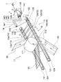
- FIG. 2 is a perspective view showing a stretchable sheet manufacturing apparatus suitably used for carrying out the manufacturing method of one embodiment of the present invention.
- FIG. 3 is a perspective view showing a configuration upstream of the rotary arm (elastic body winding means) of the apparatus shown in FIG.
- FIG. 4 is an explanatory diagram for explaining the winding speed.
- the manufacturing method of the elastic sheet of this invention is demonstrated, referring drawings based on the preferable embodiment.
- the stretchable sheet manufactured in the present embodiment is used for, for example, the waist panel 3 of the unfolded disposable diaper 1. Therefore, first, the unfoldable disposable diaper 1 using the stretchable sheet manufactured according to this embodiment for the waist panel will be described.
- the unfoldable disposable diaper 1 (hereinafter also referred to as “diaper 1”) includes a ventral side A located on the abdomen side of the wearer and a dorsal side B positioned on the dorsal side when worn. , And an absorbent main body 2 having a crotch C positioned between the abdominal side A and the back side B, and a pair of left and right waist panels 3, 3 connected to the left and right outside of the back side B And have.
- the diaper 1 has a pair of left and right panel members 4, 4 connected to the left and right outer sides of the ventral side A.
- FIG. 1 the unfoldable disposable diaper 1
- the absorptive main body 2 of the diaper 1 has a rectangular shape in a state of being expanded in a planar shape.
- the panel material 4 of the diaper 1 has a trapezoidal shape in a state of being spread in a flat shape, and the lower bottom side having a long length is formed by an absorbent body or an adhesive body by means such as adhesive or fusion. 2 is fixed.
- the longitudinal direction of the absorbent main body 2 (also the longitudinal direction of the diaper 1) will be described as the Y direction
- the width direction of the absorbent main body 2 also the width direction of the diaper 1 will be described as the X direction.
- Each of the pair of waist panels 3 and 3 has a rectangular shape in a state of being expanded in a planar shape.
- Each waist panel 3 has two sheets 5, 6 and a plurality of thread-like elastic bodies 7 arranged between the two sheets 5, 6 in an extended state.
- Each waist panel 3 is made of a stretchable sheet that is fixed between a pair of sheets 5 and 6 in a state where the thread-like elastic body 7 extends in a direction intersecting the Y direction. Specifically, as shown in FIG. 1, each waist panel 3 extends in a direction (X direction) orthogonal to the Y direction between two rectangular sheets 5 and 6 having the same shape and the same size.
- the thread-like elastic bodies are formed at substantially equal intervals in the Y direction and integrally fixed by means such as an adhesive or fusion.
- a fastening tape 8 is fixed to the rectangular waist panel 3 formed in this way at an end portion on the outer side in the X direction by means such as adhesive or fusion.
- the rectangular waist panel 3 is fixed to the back side B of the absorbent main body 2 by means such as adhesive or fusion, and the X side inward in the X direction. It is connected to the direction.
- the threadlike elastic body 7 which the waist panel 3 (elastic sheet) manufactured by this embodiment has extended
- the absorbent main body 2 includes a liquid-permeable top sheet 21, a liquid-impermeable or water-repellent back sheet 22, and a liquid-retaining property interposed between the two sheets 21 and 22. And an absorber 23.
- the absorbent main body 2 includes a top sheet 21 that forms the inner surface of the diaper 1 and a back sheet 22 that forms the outer surface of the diaper 1, with an absorber 23 interposed between the two sheets 21 and 22. It is formed by joining.
- the absorptive main body 2 is provided with three-dimensional guard forming sheets 24, 24 along both sides in the Y direction, as shown in FIG.
- the three-dimensional guard forming sheet 24 is fixed to the topsheet 21 along both sides in the Y direction of the absorbent main body 2.
- Each three-dimensional guard forming sheet 24 has a three-dimensional guard-forming elastic member 25 along the vicinity of the inner edge on the inner side in the X direction. A portion having a predetermined width is separated from the top sheet 21 to form a three-dimensional guard.
- the elastic member 26 for leg gather formation is distribute
- the material for forming the diaper 1 will be described.
- the sheets 5 and 6 and the panel material 4 a non-woven fabric, a woven fabric, a film, or a laminated sheet thereof can be used.
- the surface sheet 21 and the back surface sheet 22 constituting the absorbent main body 2 as long as they are usually used for absorbent articles such as disposable diapers, they can be used without particular limitation.
- a hydrophilic and liquid-permeable non-woven fabric can be used as the top sheet 21, and a liquid-impermeable or water-repellent resin film or a laminate of a resin film and a non-woven fabric is used as the back sheet 22.
- a liquid-impermeable or water-repellent resin film or a laminate of a resin film and a non-woven fabric is used as the back sheet 22.
- the absorbent body 23 an aggregate of fibers such as pulp fibers (may be a non-woven fabric) or an absorbent core in which water-absorbing polymer particles are held therein, a core wrap made of water-permeable thin paper or non-woven fabric. What was covered with the sheet
- a stretchable film, a nonwoven fabric, a woven fabric, or a laminated sheet thereof can be used as the three-dimensional guard.
- Examples of the elastic member 25 constituting the thread-like elastic body 7 and the three-dimensional guard include natural rubber, polyurethane, polystyrene-polyisoprene copolymer, polystyrene-polybutadiene copolymer, and polyethylene- ⁇ -olefin copolymer such as ethyl acrylate-ethylene.
- a thread-like stretchable material made of, for example, can be used.
- the filamentous elastic body in the present invention includes not only those having a circular or square cross section but also those having a narrow band shape such as an ellipse or a rectangular cross section, and a multifilament type can also be used.
- the width (or diameter) of the thread-like elastic member is, for example, 0.1 to 3 mm, and preferably 1 mm or less.
- the fastening tape 8 for example, a tape formed by attaching a hook member of a mechanical fastener to one surface of a tape base material such as a nonwoven fabric by heat fusion or an adhesive can be used.
- FIG. 2 schematically shows a production apparatus suitably used in the method for producing the waist panel 3 (elastic sheet) of this embodiment.
- the manufacturing apparatus 11 is an apparatus that continuously manufactures the elastic sheet 3 ⁇ / b> A used for the waist panel 3, and is in a direction (x direction) orthogonal to the sheet conveying direction (y direction).
- An elastic body winding rotary arm (elastic body winding means) 14 for continuously winding the thread-like elastic body 7 is provided on the pair of spaced conveyor belts 12 and 13. Further, as shown in FIGS. 2 and 3, the manufacturing apparatus 11 continuously feeds the thread-like elastic body 7 and introduces the thread-like elastic body 7 into the rotating arm 14 in an extended state.
- a conveying means 16 that conveys the thread-like elastic body 7 between the pair of belt-like sheets 50 and 60 by the pair of conveyor belts 12 and 13 and a pair of nip rollers 171 and 172 between the pair of belt-like sheets 50 and 60.
- An integration means 17 for fixing the elongated thread-like elastic body 7 and a cutting means 18 for cutting the thread-like elastic body 7 extending from both ends in the width direction of the belt-like sheets 50 and 60 are provided.
- the pair of conveying belts 12 and 13 is the longitudinal structure for yarn conveyance in the present invention, and the longitudinal direction of the longitudinal structure for yarn conveyance is the extending direction of the two conveying belts 12 and 13 ( y direction).
- the conveyance direction of the sheet is the conveyance direction of the thread-like elastic body 7 wound around the pair of conveyance belts 12 and 13 or the conveyance direction of the sheet integrated with the thread-like elastic body 7 (band-like sheets 50 and / or 60). is there.
- the y direction of the arrow in FIG. 2 indicates the conveyance direction of the thread-like elastic body 7 and the pair of belt-like sheets 50 and 60, which is the sheet conveyance direction, and finally the waist panel 3 (stretchable) manufactured according to this embodiment.
- the conveying direction of the sheet) and the conveying direction of the continuous body of the diaper 1 to which the waist panel 3 (elastic sheet) is attached are the same direction.
- the x direction of the arrow in FIG. 2 is the width direction of the belt-like sheets 50 and 60, and is the direction orthogonal to the sheet conveying direction. 2 is a direction in which a pair of nip rollers 171 and 172 described later face each other.
- the conveying belt 12 of the conveying means 16 is an endless rotating belt, and includes an upper conveying belt 12a and a lower conveying belt 12b in two upper and lower stages.
- the upper conveyance belt 12a is stretched between pulleys 121 and 122 whose rotation axis direction is arranged in the z direction.
- the lower conveyance belt 12b is bridged between pulleys 124 and 125 whose rotation axis direction is arranged in the z direction.
- the pulley 121 is located on the downstream side of the pair of nip rollers 171 and 172 for fixing the elongated elastic body 7 between the pair of belt-like sheets 50 and 60, and the pulley 122 is located on the upstream side of the nip rollers 171 and 172. Is located.
- the pulley 124 is located on the downstream side of the nip rollers 171 and 172, and the pulley 125 is located on the upstream side of the nip rollers 171 and 172.
- the pulleys 121 and 124 are arranged at the same position in two upper and lower stages. Further, the pulleys 122 and 125 are also arranged in two upper and lower stages at the same position.
- the pulley 122 (pulley 125) is located outward in the x direction from the x direction end portions of the belt-like sheets 50 and 60.
- Each of the pulley 121 and the pulley 124 is provided with a servo motor (not shown) connected to its drive unit, so that the rotational speeds of the upper conveyance belt 12a and the lower conveyance belt 12b can be changed.
- the conveying belt 13 of the conveying means 16 is an endless rotating belt, similar to the conveying belt 12, and includes an upper conveying belt 13a and a lower conveying belt 13b in two upper and lower stages.
- the upper conveyance belt 13a is stretched between pulleys 131 and 132 whose rotation axis direction is arranged in the z direction.
- the lower conveyance belt 13b is bridged between pulleys 134 and 135 whose rotation axis direction is arranged in the z direction.
- the pulley 131 is located on the downstream side of the pair of nip rollers 171 and 172, and the pulley 132 is located on the upstream side of the nip rollers 171 and 172.
- the pulley 134 is located on the downstream side of the nip rollers 171 and 172, and the pulley 135 is located on the upstream side of the nip rollers 171 and 172.
- the pulleys 131 and 134 are arranged in two upper and lower stages at the same position. Further, the pulleys 132 and 135 are also arranged in two upper and lower stages at the same position. Further, the pulley 132 (pulley 135) is positioned outward in the x direction from the x direction end portions of the belt-like sheets 50 and 60.
- Each of the pulley 131 and the pulley 134 is provided with a servo motor (not shown) connected to its drive unit, and the rotational speed of each of the upper conveyance belt 13a and the lower conveyance belt 13b can be changed.
- the conveyor belt 12 (the upper conveyor belt 12 a and the lower conveyor belt 12 b) is bridged between the pulleys 121 and 122 and the pulleys 124 and 125 arranged as described above, and the pair of nip rollers 171. , 172 from the upstream side to the downstream side.
- the conveyor belt 13 (the upper conveyor belt 13a and the lower conveyor belt 13b) is connected to the pulleys 131 and 132 and the pulleys 134 and 135 arranged as described above so that the upstream side of the pair of nip rollers 171 and 172. To the downstream side.
- the transport belt 12 (upper transport belt 12a and lower transport belt 12b) and the transport belt 13 (upper transport belt 13a and lower transport belt 13b) are located outside the belt-like sheets 50 and 60 in the x direction and are symmetrical with each other. It is arranged in.
- the transport belt 12 (upper transport belt 12a, lower transport belt 12b) and transport belt 13 (upper transport belt 13a, lower transport belt 13b) rotate so that their outer peripheral sides move in the y direction.
- the transport belt 12 (upper transport belt 12a, lower transport belt 12b) and transport belt 13 (upper transport belt 13a, lower transport belt 13b) are preferably timing belts.
- the rotation speed of a servo motor (not shown) arranged in the control unit is controlled by a control unit (not shown) included in the manufacturing apparatus 11.
- the rotating arm 14 includes an arm portion 141 having a shaft portion 142, a revolving portion 143, and a connecting portion 144, and a drive mechanism 147 that rotates the arm portion 141 around the center line of the shaft portion 142.
- the connecting portion 144 is coupled to each of the shaft portion 142 and the rotating portion 143 at an angle, and the rotating portion 143 and the shaft portion 142 are substantially parallel.
- the shaft portion 142 has an introduction port 145 for the thread-like elastic body 7 at one end thereof, and the circumferential portion 143 has a lead-out port 146 for the thread-like elastic body 7 at one end thereof, which is introduced from the introduction port 145.
- the thread-like elastic body 7 is smoothly led out from the outlet port 146 through the shaft portion 142, the connecting portion 144 and the rotating portion 143.
- Various known members a driven roll, a low friction member, etc. that can reduce friction with the thread-like elastic body 7 can be disposed in the bent portion of the arm portion 141, the outlet port 146, and the like.
- the position of the outlet 146 is downstream from the upstream end of the transport belt 12 (upper transport belt 12a, lower transport belt 12b) and transport belt 13 (upper transport belt 13a, lower transport belt 13b). It is arranged in.
- the rotary arm 14 has a servo motor 148 attached to its drive part (shaft part 142), and the rotation part 143 causes the rotation part 143 to move the conveyor belt 12 (the upper conveyor belt 12a and the lower conveyor belt 12b) by the rotation of the servo motor 148. And the outer circumference of the conveyor belt 13 (the upper conveyor belt 13a and the lower conveyor belt 13b) is circulated.
- the diameter of the locus along which the outlet 146 rotates is greater than the distance between the outer surfaces of the pair of conveyor belts 12 and 13.
- the thread-like elastic body 7 taken in is fed to the upstream end of the transport belt 12 (upper transport belt 12a, lower transport belt 12b) and transport belt 13 (upper transport belt 13a, lower transport belt 13b). It is a part and can be continuously wound on each outer peripheral side.
- the rotation speed of the rotary arm 14, that is, the rotation speed of the servo motor 148 is controlled by a control unit (not shown) included in the manufacturing apparatus 11.
- the elastic body supply means 15 includes means for pulling out the thread-like elastic body 7 from the bobbin 70, tension adjusting means 15A for applying a predetermined tension to the thread-like elastic body 7 drawn out from the bobbin 70, and tension adjustment.
- a speed adjusting means 15B for adjusting the speed of the thread-like elastic body 7 fed from the tension adjusting means 15A and introducing it into the rotating arm (elastic body winding means) 14 is provided downstream of the means 15A. Yes.
- the tension adjusting means 15 ⁇ / b> A is located on the downstream side of the bobbin 70, the tensioner 151 for applying tension to the thread-like elastic body 7 by the brake, the feeding roller 152 located on the downstream side of the tensor 151, and the downstream side of the feeding roller 152. And a tension measuring device 153.
- the feeding roller 152 has a rotational axis direction in the x direction.
- a servo motor (not shown) is attached to the driving portion of the feeding roller 152.
- the feeding roller 152 is used with the thread-like elastic body 7 wound around its outer periphery once or a plurality of times (preferably twice).
- the feeding roller 152 used in this embodiment also serves as the whole or a part of the above-described drawing means, and the thread-like elastic body 7 drawn from the bobbin 70 by the drawing roller 152 passes through the guide hole of the guide member 150. Are introduced into the tensor 151.
- the tension adjusting unit 15A detects the tension of the thread-like elastic body 7 between the feeding roller 152 and the guide roller 155 by the tension measuring device 153, and the tension measuring device 153 by a control unit (not shown) included in the manufacturing apparatus 11.
- the rotational speed of the feeding roller 152 is controlled in a foot-back manner based on the detection output from. Thereby, the tension of the thread-like elastic body 7 sent out from the guide roller 155 can be adjusted to the set predetermined tension.
- the speed adjusting means 15B adjusts the speed of the thread-like elastic body 7 sent out from the tension adjusting means 15A, and introduces the speed-adjusted thread-like elastic body 7 into the rotating arm (elastic body winding means) 14.
- the speed adjusting unit 15 ⁇ / b> B includes a feed roller 156 in the vicinity of the rotating arm 14.
- the feed roller 156 is disposed between the rotating arm 14 and the feeding roller 152, and the rotation axis direction thereof is disposed in the x direction.
- Guide rollers 156a and 156b are arranged before and after the feed roller 156.
- the feed roller 156 has a servo motor (not shown) attached to its drive unit.
- the rotation speed of the servo motor (not shown), that is, the rotation speed of the feed roller 156 is controlled by a control unit (not shown) provided in the manufacturing apparatus 11. It is preferable that the feed roller 156 is disposed in the vicinity of the rotating arm 14, particularly immediately before the feed path of the thread-like elastic body.
- the length of the conveyance path of the thread-like elastic body from the time when it leaves the feed roller 156 until it is introduced into the rotation arm 14 is 10 times the total length of the conveyance path of the thread-like elastic body from the bobbin 70 to the rotation arm 14. It is preferably ⁇ 50%, more preferably 10 to 30%.
- Integral means 17 includes a pair of nip rollers 171 and 172 as shown in FIGS.
- a metal cylindrical roller or a cylindrical roller made of low hardness silicon rubber can be used as the pair of nip rollers 171, 172.
- the pair of nip rollers 171 and 172 has a servo motor (not shown) attached to one of the drive units, and the rotation speed is controlled by a control unit (not shown) included in the manufacturing apparatus 11.
- Drive transmission gears are attached to the rotation shafts of the pair of nip rollers 171 and 172, respectively.
- the rotation speed of a servo motor (not shown), that is, the rotation speed of one of the nip rollers 171 and 172 can be controlled based on the production speed of the stretchable sheet.
- the driving force is transmitted to the other nip rollers 172 and 171, and the pair of nip rollers 171 and 172 can be rotated.
- the bearing portions of the pair of nip rollers 171 and 172 use a force such as hydraulic pressure, pneumatic pressure, or spring in order to securely fix the elongated elastic body between the pair of belt-like sheets 50 and 60, Each bearing part is pressurized.
- the pair of nip rollers 171 and 172 includes an inner peripheral side of the transport belt 12 (upper transport belt 12a and lower transport belt 12b) and a transport belt 13 (upper transport belt 13a and lower transport belt 13b). It is located between the inner circumference side.
- the cutting means 18 includes a cutter 180 having a sharp cutting blade where the conveyed elastic elastic body 7 contacts (the cutter 180 on the conveyor belt 13 side is not shown).
- the cutter 180 is disposed by a support (not shown) at a position where the thread-like elastic body 7 hits, and the thread-like elastic body 7 is cut by being conveyed by the conveyor belts 12 and 13 and being pressed against the cutter 180.
- the cutting means 18 includes a pair of nip rollers 171, 172, pulleys 121, 124 of the conveyor belt 12 (upper conveyor belt 12a, lower conveyor belt 12b), and conveyor belt 13 (upper conveyor belt 13a, lower conveyor).
- the position in the x direction where the thread-like elastic body 7 is cut by the cutting means 18 may be between the nip rollers 171 and 172 and the conveyor belts 12 and 13, or the inner and outer circumferences of the conveyor belts 12 and 13, respectively. May be between the outer peripheral portions of the conveyor belts 12 and 13.
- the cutting means 18 various known ones that can cut the thread-like elastic body 7 can be used without particular limitation.
- a cutter roller having a cutting blade extending in the circumferential direction on the outer peripheral surface and the cutting blade It is also possible to use a roller cutter or the like equipped with an anvil roller for receiving the same. Moreover, you may cut
- the thread-like elastic body 7 is continuously fed out, and the fed-out thread-like elastic body 7 is introduced into a rotating arm 14 as an elastic body winding means in a stretched state (supplying step). More specifically, the thread-like elastic body 7 is continuously pulled out from the bobbin 70 using the feeding roller 152. In this embodiment, the bobbin 70 does not rotate, but may rotate. Then, a predetermined tension is applied to the thread-like elastic body 7 drawn out from the bobbin 70 by the tension adjusting means 15A. More specifically, the tension measuring device 153 detects the tension of the thread-like elastic body 7 between the feeding roller 152 and the guide roller 155, and the tension measuring device 153 is controlled by a control unit (not shown) included in the manufacturing apparatus 11.
- a control unit not shown
- the rotational speed of the feeding roller 152 and the brake of the tensor 151 are adjusted based on the detection output from the guide roller 155 and the thread-like elastic body 7 adjusted to a predetermined tension (predetermined expansion ratio) from the guide roller 155 toward the downstream side. Send out tension.
- the brake of the tensor 151 is provided so that the sudden slack of the thread-like elastic body that may occur when the tensor 151 is pulled out from the bobbin 70 does not affect the downstream process.
- a preferable range of the expansion ratio of the thread-like elastic body in the elastic sheet to be manufactured by adjusting the tension by the tension adjusting means 15A is 1.5 to 4.0 times, more preferably 1.8 to 3.5 times. More preferably, it is 2.0 to 3.0 times.
- the thread-like elastic body 7 is introduced into the rotary arm 14.
- the thread-like elastic body 7 stretched to a predetermined tension (a predetermined expansion ratio) by the tension adjusting means 15A described above.
- the speed is adjusted to a speed equal to or higher than the winding speed at which the thread-like elastic body 7 is wound around the pair of transport belts 12 and 13 by the rotating arm 14 (elastic body winding means) by the speed adjusting means 15B.
- the time T is the time when the thread-like elastic body 7 that circulates on the outer peripheral side of the conveyor belt 12 and the outer peripheral side of the conveyor belt 13 moves in the y direction.
- the elastic body winding means is a rotating arm .
- the circumferential length L is calculated by taking the total length of the portions a to d in the figure in consideration of the movement of the conveyor belt and the movement of the thread-like elastic body.
- the speed adjustment means 15B arranged upstream of the rotating arm 14 adjusts the speed of the thread-like elastic body 7 introduced into the rotating arm 14 to a speed equal to or higher than the winding speed.
- an elastic sheet having a certain elastic property can be stably produced regardless of the production speed.
- the manufacturing method of the elastic sheet of this embodiment can be implemented with a comparatively simple installation and process as above-mentioned.
- the speed [m / sec] of the thread-like elastic body 7 introduced into the rotary arm 14 is preferably 95 to 200% of the winding speed [m / sec]. More preferably, it is 100 to 150%, and still more preferably 110 to 120%.
- the speed of the thread-like elastic body 7 introduced into the rotating arm 14 being equal to the winding speed means that the speed of the thread-like elastic body 7 introduced into the rotating arm 14 is 95 to 105% of the winding speed. . It is more preferable that the speed of the thread-like elastic body 7 introduced into the rotating arm 14 is equal to or higher than the winding speed, particularly higher than the winding speed.
- the stretched elastic elastic body 7 is continuously wound around the pair of transport belts 12 and 13 by using the rotating arm 14, and the pair of transport belts 12 and 13.
- the thread-like elastic body 7 that is continuously wound using is conveyed between the pair of belt-like sheets 50 and 60 (conveying step). More specifically, the thread-like elastic body 7 supplied into the rotating arm 14 in the extended state is introduced into the arm portion 141 from the introduction port 145, passes through the shaft portion 142, the connecting portion 144, and the rotating portion 143. Derived from the outlet 146.
- the thread-like elastic body 7 led out from the lead-out port 146 is led out while the rotary arm 14 is rotated, so that the outer peripheral side at the upstream end of the transport belt 12 (upper transport belt 12a, lower transport belt 12b) and The conveyor belt 13 (upper conveyor belt 13a, lower conveyor belt 13b) is wound around the outer peripheral side at the upstream end.
- the conveyor belt 12 (upper conveyor belt 12a, lower conveyor belt 12b) and the conveyor belt 12 (upper conveyor belt 12a, lower conveyor belt 12b) are rotated by the rotational travel of the conveyor belt 12 (upper conveyor belt 12a, lower conveyor belt 12b).
- the thread-like elastic body 7 is continuously wound in a spiral shape.
- the continuously wound thread-like elastic body 7 is conveyed between the pair of downstream belt-like sheets 50 and 60.
- the thread-like elastic body 7 wound around the pair of transport belts 12 and 13 extends in a direction intersecting the y direction, and is not arranged in a direction orthogonal to the y direction.
- the rotational speed of the upper transport belt 12 a is made slower than the rotational speed of the lower transport belt 12 b
- the rotational speed of the lower transport belt 13 b is made slower than the rotational speed of the upper transport belt 13 a in the transport belt 13.
- the inclination of the thread-like elastic body 7 is gradually changed during the conveyance in the y-direction, and the inclination of the thread-like elastic body 7 is orthogonal to the y-direction before being conveyed between the pair of belt-like sheets 50 and 60 ( x direction).
- the belt-like sheet 50 is previously folded at both ends in the x direction on the outer surface side by a sailor (not shown) or the like, and the conveyor belt 12 (upper conveyor belt 12a, lower conveyor belt 12b). ) And the conveyor belt 13 (upper conveyor belt 13a, lower conveyor belt 13b) from the upper side of the nip rollers 171 and 172.
- a sailor not shown
- the conveyor belt 13 upper conveyor belt 13a, lower conveyor belt 13b
- the belt-like sheet 60 is previously folded at both ends in the x direction on the outer surface side by a sailor (not shown) or the like, and the conveyance belt 12 (upper conveyance belt 12a, lower conveyance)
- the belt 12b) and the conveyor belt 13 are supplied between a pair of nip rollers 171 and 172 from the lower side.
- the adhesive agent is apply
- the adhesive may be applied in a stripe shape, a spiral shape, a sine wave shape, or the like, or may be sprayed on the entire surface or applied in a solid shape.
- the thread-like elastic body 7 is fixed in an extended state between the pair of belt-like sheets 50 and 60 using the nip rollers 171 and 172 (integration step). More specifically, a continuous body in which the continuously wound thread-like elastic body 7 is disposed between the pair of belt-like sheets 50 and 60 is supplied between the pair of nip rollers 171 and 172, and the pair of belt-like sheets 50. , 60 is fixed in a stretched state.
- the thread-like elastic body 7 extending from both ends in the width direction (x direction) of the pair of belt-like sheets 50 and 60 is cut with the cutter 180 described above (cutting step).
- both ends in the x direction of the belt-like sheets 50 and 60 folded on the outer surface side are refolded by a sailor (not shown) or the like, and the thread-like elastic body 7 is placed between the pair of belt-like sheets 50 and 60.
- a belt-like stretchable sheet fixed in a state of extending in a direction crossing the direction can be continuously produced.
- the manufactured belt-like stretchable sheet is intermittently cut in the x direction by a known cutting means (not shown).
- the interval of intermittently cutting is the same as the size of the waist panel 3 provided in the diaper 1. Thereby, the waist panel 3 (elastic sheet) can be manufactured continuously.
- the continuous body of the absorptive main body 2 is manufactured at another process by a well-known method.
- the continuous body of the absorbent main body 2 includes a plurality of absorbent bodies intermittently in the transport direction (y direction) between the continuous body of the top sheet 21, the continuous body of the back sheet 22, and the continuous body of both sheets 21 and 22. 23, 23... Are arranged, and a continuous body of a plurality of elastic members 25 and a three-dimensional guard forming sheet 24 are arranged on both sides in the conveying direction (y direction) of the continuous body of the topsheet 21. .
- a pair of waist panels 3 are included in the continuous body of the absorbent main body 2 so as to protrude outward in the x direction while transporting the manufactured continuous body of the absorbent main body 2 in the transport direction (y direction).
- the continuous body of the diaper 1 distribute
- the conveyance direction (y direction) of the continuous body of the absorbent main body 2 and the conveyance direction (y direction) when manufacturing the waist panel 3 (elastic sheet) are the same direction, and the waist panel 3 (extension and contraction). It is not necessary to invert the adhesive sheet) by 90 °. Thereafter, the continuum can be cut into the dimensions of the individual diaper 1 by a known cutting means (not shown) to manufacture the diaper 1.
- the method for producing the stretchable sheet of the present invention is not limited to the above-described embodiment, and can be changed as appropriate.
- the pair of waist panels 3 and 3 are rectangular, but may be trapezoids or parallelograms.
- the pair of waist panels 3 and 3 are cut and formed from the stretchable sheet, it is preferable to have a shape having as few portions as possible to be discarded.
- the inclination of the thread-like elastic body 7 is corrected in the direction orthogonal to the y-direction (x-direction), but is fixed to the pair of belt-like sheets 50 and 60 without being corrected at the angle wound around the conveyor belt 12. May be.
- the elastic body winding means includes a disk having a thread-like elastic body introducing portion at the rotating shaft portion and an arm protruding downstream from the disk in the y direction. It is also possible to use one that wraps around the belt and winds the elastic thread around the conveyor belts 12 and 13. Further, as the feed roller 156, as shown in FIG. 2, instead of a material (thread-like elastic body) wound around and feeding the material, a feed roller 156 sandwiching the material with a nip roll may be used. it can. Further, instead of fixing a thread-like elastic body between the pair of nip rolls 170, 171 by introducing a band-like sheet having a narrow width by folding back both ends in the width direction to the respective outer surface sides. Between the nip rolls 170 and 171, a belt-like sheet whose both ends in the width direction are not folded back may be introduced, and the thread-like elastic body may be fixed between the belt-like sheets.
- a conveyor belt as disclosed in WO2005 / 060910 may be used instead of a pair of conveyor belts. In this case, only one conveyor belt may be used.
- a thread support member provided with screw grooves described in FIGS. 4 to 6 of JP-A No. 2002-192641 may be used as the longitudinal structure for thread conveyance.
- the present invention further discloses the following manufacturing method or manufacturing method of the absorbent article.
- a method for producing a stretchable sheet which continuously produces a stretchable sheet that is fixed in a state where a thread-like elastic body is stretched in a direction intersecting the transport direction of the beltlike sheet between a pair of striplike sheets,
- the thread-like elastic body is equal to or higher than the winding speed of the longitudinal structure for yarn conveyance by speed adjusting means arranged upstream of the elastic body winding means.
- a method for producing a stretchable sheet that is adjusted to the speed of the elastic body and introduced into the elastic body winding means.
- the tension is adjusted to a constant tension by a tension adjusting unit arranged on the upstream side of the speed adjusting unit, and the speed of the filamentous elastic body is adjusted by the speed adjusting unit.
- the speed adjusting means includes a feed roller and a guide roller, and adjusts the speed of the thread-like elastic body by increasing or decreasing the rotational speed of the feed roller.
- ⁇ 1> to ⁇ 3 The method for producing an elastic sheet according to any one of the above. ⁇ 5> While feeding out the threadlike elastic body from the bobbin, The length of the conveyance path of the thread-like elastic body from the time when it leaves the feed roller until it is introduced into the elastic body winding means is the total length of the conveyance path of the thread-like elastic body from the bobbin to the elastic body winding means.
- the tension adjusting means includes a tensor for applying tension to the thread-like elastic body by a brake, a feeding roller positioned on the downstream side of the tensor, and a tension measuring device. Detection from the tension measuring device The method for producing a stretchable sheet according to any one of ⁇ 1> to ⁇ 5>, wherein the tension of the thread-like elastic body is adjusted by increasing / decreasing the rotational speed of the feeding roller based on an output.
- the speed of the thread-like elastic body introduced into the elastic body winding means is 95 to 200%, more preferably 100 to 150%, still more preferably 110% of the winding speed with respect to the yarn transporting longitudinal structure.
- the stretchable sheet produced by the production method of the present invention includes a waist part of a developed or pant-type disposable diaper, a waist part of a pant-type disposable diaper, and a pant-type sanitary garment. It can also be used for napkins, disposable underwear, disposable mask ear hooks, cleaning sheets, bandages and the like.
- Example 1 The stretchable sheet in which the thread-like elastic body 7 was fixed between the belt-like sheets 50 and 60 was produced using the stretchable sheet manufacturing apparatus shown in FIG.
- the tension of the thread-like elastic body 7 drawn out from the bobbin 70 is expanded and contracted by a tension adjusting means 15A including a feeding roller 152 (a thread rubber tension measured by a tension measuring device 153).
- the speed is adjusted within the range of 0 to 100 gf so as to obtain a desired stretching stress of the adhesive sheet (85 gf in Example 1), and the speed adjustment using the feed roller 156 as a main element.
- the speed of the thread-like elastic body 7 was adjusted so as to be 115% of the winding speed around the conveyor belt, and introduced into the rotary arm 14.
- the winding length L1 is 1362 m
- the winding time T is 60 seconds
- the winding speed (L1 / T) is 22.7 m / sec (1362 m / min).
- the conveyance speed of the elastic sheet was 16.8 m / min. It was 1.9 times when the expansion ratio of the threadlike elastic body in the obtained elastic sheet was measured.
- the elastic sheet was manufactured by changing the conveying speed of the elastic sheet to 33.6 m / min, 50.4 m / min, and 67.2 m / min in order.
- the tension control by the tension adjusting unit 15A and the introduction speed control by the speed adjusting unit 15B are performed so that the thread rubber tension measured by the tension measuring device 153 becomes the desired stretching stress of the stretchable sheet. Is set within the range of 0 to 100 gf. In this example, the process was performed to 85 gf. The elongation ratio of the thread-like elastic body in the obtained stretchable sheet was 1.9 times in all results.
- Example 2 A stretchable sheet was produced in the same manner as in Example 1 except that the speed of the thread-like elastic body 7 adjusted by the speed adjusting means 15B was set to 100% of the winding speed with respect to the conveying belt.
- the expansion ratio of the thread-like elastic body in the obtained stretchable sheet was 2.0 times, 2.0 times, and 2.1 times in this order.
- Example 1 A stretchable sheet was produced in the same manner as in Example 1 except that the speed adjusting unit 15B was removed from the apparatus used in Example 1 and the speed control by the speed adjusting unit 15B was not performed. Subsequently, the peripheral speeds of the rollers 171 and 172 were changed in order to 33.6 m / min, 50.4 m / min, and 67.2 m / min to produce elastic sheets.
- the tension control by the tension adjusting means 15A similarly to the above case, the thread rubber tension measured by the tension measuring device 153 is set within the range of 0 to 100 gf so as to be a desired stretching stress of the stretchable sheet. . Comparative example 1 was also performed to be 85 gf.
- the expansion ratio of the thread-like elastic body in the obtained stretchable sheet was 2.2 times, 2.4 times, and 3.0 times in order.
- an elastic sheet in which a thread-like elastic body is fixed between a pair of belt-like sheets in an extended state in a direction intersecting the conveying direction of the belt-like sheet is continuously produced.
- a method for producing a stretchable sheet which can stably produce a stretchable sheet having a certain stretch property regardless of the production rate.
Abstract
Description
本実施態様で製造する伸縮性シートは、図1に示すように、例えば、展開型の使い捨ておむつ1のウエストパネル3に用いられる。従って、先ず、本実施態様により製造される伸縮性シートをウエストパネルに用いた展開型の使い捨ておむつ1について説明する。 Hereinafter, the manufacturing method of the elastic sheet of this invention is demonstrated, referring drawings based on the preferable embodiment.
As shown in FIG. 1, the stretchable sheet manufactured in the present embodiment is used for, for example, the
以下の説明では、吸収性本体2の長手方向(おむつ1の長手方向でもある)をY方向、吸収性本体2の幅方向(おむつ1の幅方向でもある)をX方向として説明する。 As shown in FIG. 1, the unfoldable disposable diaper 1 (hereinafter also referred to as “
In the following description, the longitudinal direction of the absorbent main body 2 (also the longitudinal direction of the diaper 1) will be described as the Y direction, and the width direction of the absorbent main body 2 (also the width direction of the diaper 1) will be described as the X direction.
ウエストパネル3を構成するシート5,6及びパネル材4としては、通常、使い捨ておむつ等の吸収性物品に用いられるものであれば、特に制限なく用いることができる。例えば、シート5,6及びパネル材4としては、不織布、織物、フィルムまたはそれらの積層シート等を用いることができる。吸収性本体2を構成する表面シート21、裏面シート22としては、それぞれ、通常、使い捨ておむつ等の吸収性物品に用いられるものであれば、特に制限なく用いることができる。例えば、表面シート21としては、親水性且つ液透過性の不織布等を用いることができ、裏面シート22としては、液不透過性又は撥水性の樹脂フィルムや樹脂フィルムと不織布の積層体等を用いることができる。吸収体23としては、パルプ繊維等の繊維の集合体(不織布であっても良い)又はこれに吸水性ポリマーの粒子を保持させてなる吸収性コアを、透水性の薄紙や不織布からなるコアラップシートで被覆したもの等を用いることができる。立体ガードを構成する立体ガード形成用シート24としては、伸縮性のフィルム、不織布、織物またはそれらの積層シート等を用いることができる。 The material for forming the
As the sheet |
図2は、本実施態様のウエストパネル3(伸縮性シート)の製造方法に好適に用いられる製造装置を模式的に示したものである。 Next, the preferable embodiment of the manufacturing method of the elastic sheet of this invention is demonstrated, referring an example for the case where the waist panel 3 (elastic sheet) of the
FIG. 2 schematically shows a production apparatus suitably used in the method for producing the waist panel 3 (elastic sheet) of this embodiment.
本実施態様においては、一対の搬送ベルト12,13が、本発明における糸搬送用長手構造体であり、該糸搬送用長手構造体の長手方向は、両搬送ベルト12,13の延設方向(y方向)である。 As shown in FIG. 2, the
In this embodiment, the pair of conveying
図2中矢印のy方向は、シートの搬送方向である、糸状弾性体7や一対の帯状シート50,60の搬送方向を示し、最終的に本実施態様により製造されるウエストパネル3(伸縮性シート)の搬送方向及び該ウエストパネル3(伸縮性シート)を取り付けたおむつ1の連続体の搬送方向とも同じ方向である。
また、図2中矢印のx方向は、帯状シート50,60の幅方向であり、シートの搬送方向と直交する方向である。また、図2中矢印のz方向は、後述する一対のニップローラー171,172どうしが対向する方向である。 The conveyance direction of the sheet is the conveyance direction of the thread-like
The y direction of the arrow in FIG. 2 indicates the conveyance direction of the thread-like
Also, the x direction of the arrow in FIG. 2 is the width direction of the belt-
このような回転アーム14により、取り込んだ糸状弾性体7を、搬送ベルト12(上段搬送ベルト12a,下段搬送ベルト12b)及び搬送ベルト13(上段搬送ベルト13a,下段搬送ベルト13b)の上流側の端部であって且つそれぞれの外周側に連続的に巻回することができる。回転アーム14の回転速度、即ち、サーボモーター148の回転速度は、製造装置11の備える制御部(不図示)により、制御されている。 In the
By such a
テンション調整手段15Aは、ボビン70の下流側に位置して糸状弾性体7にブレーキによりテンションをかけるテンサー151と、テンサー151の下流側に位置する繰り出しローラー152と、繰り出しローラー152の下流側に位置するテンション測定器153とを備えている。繰り出しローラー152は、その回転軸方向がx方向に配されている。繰り出しローラー152には、その駆動部にサーボモーター(不図示)が取り付けられている。繰り出しローラー152は、その外周に糸状弾性体7が1回又は複数回(好ましくは2回)巻き付けられて使用される。本実施態様で用いた繰り出しローラー152は、前記の引き出し手段の全体又は一部を兼ねており、繰り出しローラー152によって、ボビン70から引き出された糸状弾性体7が、ガイド部材150のガイド孔を通ってテンサー151に導入される。 As shown in FIG. 3, the elastic body supply means 15 includes means for pulling out the thread-like
The tension adjusting means 15 </ b> A is located on the downstream side of the
フィードローラー156は、糸状弾性体の搬送経路において、回転アーム14の近傍、特に直前に配置されていることが好ましい。例えば、フィードローラー156を離れてから回転アーム14に導入されるまでの糸状弾性体の搬送経路の長さは、ボビン70から回転アーム14までの糸状弾性体の搬送経路の全長に対して、10~50%であることが好ましく、より好ましくは10~30%であることが好ましい。 The speed adjusting means 15B adjusts the speed of the thread-like
It is preferable that the
切断手段18により糸状弾性体7を切断するx方向の位置は、ニップローラー171,172と搬送ベルト12,13との間であっても良いし、搬送ベルト12,13それぞれの内周部と外周部との間であっても良いし、搬送ベルト12,13それぞれの外周部の外側であっても良い。また、切断手段18としては、糸状弾性体7を切断し得る各種公知のものを特に制限なく使用することができ、例えば、外周面に周方向に亘る切断刃を備えたカッターローラーと該切断刃を受けるアンビルローラーとを備えたローラーカッター等を用いることもできる。また、レーザーや熱等により切断してもよい。 As shown in FIG. 2, the cutting means 18 includes a
The position in the x direction where the thread-like
詳述すると、繰り出しローラー152を用いて、ボビン70から糸状弾性体7を連続して引き出す。本実施態様では、ボビン70は、回転しないものであるが、回転するものであっても良い。そして、ボビン70から引き出された糸状弾性体7にテンション調整手段15Aにより所定のテンションをかける。より具体的には、テンション測定器153により、繰り出しローラー152とガイドローラー155との間の糸状弾性体7のテンションを検出し、製造装置11の備える制御部(不図示)により、テンション測定器153からの検出出力に基づき、繰り出しローラー152の回転速度やテンサー151のブレーキを調整し、ガイドローラー155から下流側に向かって、所定のテンション(所定の伸長倍率)に調整された糸状弾性体7のテンションを送り出す。なお、テンサー151のブレーキは、ボビン70から引き出す際に生じることのある糸状弾性体の急激な弛みが下流工程に影響を与えないように設けてある。 First, as shown in FIG. 3, the thread-like
More specifically, the thread-like
伸長倍率は下記の式で求められる。
伸長倍率=(伸ばされた糸状弾性体の長さ)÷(伸ばされていない糸状弾性体の長さ(糸状弾性体の自然長さ)) A preferable range of the expansion ratio of the thread-like elastic body in the elastic sheet to be manufactured by adjusting the tension by the tension adjusting means 15A is 1.5 to 4.0 times, more preferably 1.8 to 3.5 times. More preferably, it is 2.0 to 3.0 times.
The expansion ratio is obtained by the following formula.
Elongation magnification = (Length of stretched filamentous elastic body) ÷ (Length of unstretched filamentous elastic body (natural length of filamentous elastic body))
前記時間Tは、図4に示すように、y方向に移動しながら、搬送ベルト12の外周側及び搬送ベルト13の外周側を周回する糸状弾性体7が、搬送ベルト12及び搬送ベルト13の周囲における、ある特定の位置(例えば図4中P1の位置)を通った後、再びその位置(例えば図4中P2の位置)を通る迄の時間であり、弾性体巻回手段が回転アームの場合、該回転アームが1回転する時間と等しい。他方、前記周回長さLは、図4に示すように、搬送ベルトの移動及びそれによる糸状弾性体の移動を考慮して、図中の部分a~dの長さの合計を該長さL1とする。 Here, the “winding speed” means one round of rotation around the outer peripheral side of the transport belt 12 (
As shown in FIG. 4, the time T is the time when the thread-like
この製造された吸収性本体2の連続体を、搬送方向(y方向)に搬送しながら、x方向両外方に突出するように一対のウエストパネル3を、吸収性本体2の連続体に含まれる吸収体33毎に配したおむつ1の連続体を製造する。ここで、吸収性本体2の連続体の搬送方向(y方向)と、ウエストパネル3(伸縮性シート)を製造する際の搬送方向(y方向)は、同方向であり、ウエストパネル3(伸縮性シート)を90°反転する必要はない。その後、その連続体を、公知の切断手段(図示せず)により、個々のおむつ1の寸法に切断して、おむつ1を製造することができる。 As a manufacturing method of the
A pair of
また、一対のニップロール170,171間に、幅方向両端部をそれぞれの外面側に折り返して細幅にした帯状シートを導入し、その帯状シート間に糸状弾性体を固定するのに代えて、一対のニップロール170,171間に、幅方向両端部が折り返していない帯状シートを導入し、その帯状シート間に糸状弾性体を固定しても良い。 The elastic body winding means includes a disk having a thread-like elastic body introducing portion at the rotating shaft portion and an arm protruding downstream from the disk in the y direction. It is also possible to use one that wraps around the belt and winds the elastic thread around the
Further, instead of fixing a thread-like elastic body between the pair of nip rolls 170, 171 by introducing a band-like sheet having a narrow width by folding back both ends in the width direction to the respective outer surface sides. Between the nip rolls 170 and 171, a belt-like sheet whose both ends in the width direction are not folded back may be introduced, and the thread-like elastic body may be fixed between the belt-like sheets.
前記糸状弾性体を連続して繰り出し、繰り出された該糸状弾性体を弾性体巻回手段に導入する供給工程と、該弾性体巻回手段を用いて前記糸状弾性体を、糸搬送用長手構造体に連続的に巻回し、巻回した該糸状弾性体を、該糸搬送用長手構造体の長手方向に搬送する搬送工程と、搬送した該糸状弾性体をシート間に挟んで固定する一体化工程とを備え、前記供給工程においては、前記弾性体巻回手段の上流側に配した速度調整手段により、前記糸状弾性体を、前記糸搬送用長手構造体に対する巻回速度と同等又はそれ以上の速度に調整して、該弾性体巻回手段に導入する伸縮性シートの製造方法。 <1> A method for producing a stretchable sheet, which continuously produces a stretchable sheet that is fixed in a state where a thread-like elastic body is stretched in a direction intersecting the transport direction of the beltlike sheet between a pair of striplike sheets,
A feeding step of continuously feeding out the thread-like elastic body and introducing the fed-out thread-like elastic body into an elastic body winding means; and a longitudinal structure for transferring the thread-like elastic body using the elastic body winding means. Integration that continuously winds around the body, transports the wound thread-like elastic body in the longitudinal direction of the longitudinal structure for thread transportation, and fixes the transported thread-like elastic body between sheets And in the supplying step, the thread-like elastic body is equal to or higher than the winding speed of the longitudinal structure for yarn conveyance by speed adjusting means arranged upstream of the elastic body winding means. A method for producing a stretchable sheet that is adjusted to the speed of the elastic body and introduced into the elastic body winding means.
<3>前記糸搬送用長手構造体が、該糸搬送用長手構造体の長手方向と直交する方向に離間した一対の搬送ベルトである、前記<1>又は<2>に記載の伸縮性シートの製造方法。
<4>前記速度調整手段は、フィードローラー及びガイドローラーを備えており、前記フィードローラーの回転速度を増減して、前記糸状弾性体の速度を調整するものである、前記<1>~<3>の何れか1に記載の伸縮性シートの製造方法。
<5>前記糸状弾性体をボビンから繰り出すと共に、
前記フィードローラーを離れてから前記弾性体巻回手段に導入されるまでの糸状弾性体の搬送経路の長さを、前記ボビンから前記弾性体巻回手段までの糸状弾性体の搬送経路の全長に対して10~50%とし、より好ましくは10~30%とする、前記<1>~<4>の何れか1に記載の伸縮性シートの製造方法。
<6>前記テンション調整手段は、前記糸状弾性体にブレーキによりテンションをかけるテンサーと、該テンサーの下流側に位置する繰り出しローラーと、テンション測定器とを備えており、前記テンション測定器からの検出出力に基づき、前記繰り出しローラーの回転速度を増減して、前記糸状弾性体のテンションを調整するものである、前記<1>~<5>の何れか1にの伸縮性シートの製造方法。
<7>前記弾性体巻回手段に導入する糸状弾性体の速度を、前記糸搬送用長手構造体に対する巻回速度の95~200%とし、より好ましくは100~150%とし、更に好ましくは110~120%とする、前記<1>~<6>の何れか1に記載の伸縮性シートの製造方法。
<8>伸縮性シートを用いたウエストパネルを具備する使い捨ておむつの製造方法であって、前記伸縮性シートを、前記<1>~<7>の何れか1に記載の伸縮性シートの製造方法により製造する、吸収性物品の製造方法。 <2> In the supplying step, the tension is adjusted to a constant tension by a tension adjusting unit arranged on the upstream side of the speed adjusting unit, and the speed of the filamentous elastic body is adjusted by the speed adjusting unit. The method for producing a stretchable sheet according to <1>, which is introduced into the elastic body winding means.
<3> The elastic sheet according to <1> or <2>, wherein the longitudinal structure for yarn conveyance is a pair of conveyance belts separated in a direction perpendicular to the longitudinal direction of the longitudinal structure for yarn conveyance. Manufacturing method.
<4> The speed adjusting means includes a feed roller and a guide roller, and adjusts the speed of the thread-like elastic body by increasing or decreasing the rotational speed of the feed roller. <1> to <3 The method for producing an elastic sheet according to any one of the above.
<5> While feeding out the threadlike elastic body from the bobbin,
The length of the conveyance path of the thread-like elastic body from the time when it leaves the feed roller until it is introduced into the elastic body winding means is the total length of the conveyance path of the thread-like elastic body from the bobbin to the elastic body winding means. The method for producing a stretchable sheet according to any one of <1> to <4>, wherein the content is 10 to 50%, more preferably 10 to 30%.
<6> The tension adjusting means includes a tensor for applying tension to the thread-like elastic body by a brake, a feeding roller positioned on the downstream side of the tensor, and a tension measuring device. Detection from the tension measuring device The method for producing a stretchable sheet according to any one of <1> to <5>, wherein the tension of the thread-like elastic body is adjusted by increasing / decreasing the rotational speed of the feeding roller based on an output.
<7> The speed of the thread-like elastic body introduced into the elastic body winding means is 95 to 200%, more preferably 100 to 150%, still more preferably 110% of the winding speed with respect to the yarn transporting longitudinal structure. The method for producing a stretchable sheet according to any one of <1> to <6>, wherein the stretchable sheet is set to 120%.
<8> A method for manufacturing a disposable diaper having a waist panel using an elastic sheet, wherein the elastic sheet is a method for manufacturing the elastic sheet according to any one of <1> to <7>. The manufacturing method of an absorbent article manufactured by this.
図2に示す伸縮性シートの製造装置を用いて、帯状シート50,60の間に糸状弾性体7が固定された伸縮性シートを製造した。その伸縮性シートの製造に際しては、ボビン70から引き出した糸状弾性体7のテンションを、繰り出しローラー152を含むテンション調整手段15Aにより、一定のテンション(テンション測定器153で計測される糸ゴムテンションを伸縮性シートの所望の伸縮応力になるように、0~100gf範囲内で設定する。実施例1では85gfとした。)になるように制御し、また、フィードローラー156を主要な要素とする速度調整手段15Bにより、その糸状弾性体7の速度を、搬送ベルトに対する巻回速度の115%の速度となるように調整して、回転アーム14に導入した。回転アーム14により糸状弾性体を巻回する際の、巻回長さL1は1362m、巻回時間Tは60秒、巻回速度(L1/T)は22.7m/sec(1362m/min)であった。また、伸縮性シートの搬送速度(伸縮性シートのローラー171,172間からの引き出し速度であり、ローラー171,172の周速と同じである。)は、16.8m/minであった。
得られた伸縮性シートにおける糸状弾性体の伸長倍率を、測定したところ、1.9倍であった。 [Example 1]
The stretchable sheet in which the thread-like
It was 1.9 times when the expansion ratio of the threadlike elastic body in the obtained elastic sheet was measured.
速度調整手段15Bにより調整する糸状弾性体7の速度を、搬送ベルトに対する巻回速度の100%の速度とした以外は、実施例1と同様にして伸縮性シートを製造した。得られた伸縮性シートにおける糸状弾性体の伸長倍率は、順に、2.0倍、2.0倍、2.1倍であった。 [Example 2]
A stretchable sheet was produced in the same manner as in Example 1 except that the speed of the thread-like
実施例1で使用した装置から、速度調整手段15Bを取り除き、該速度調整手段15Bによる速度制御を行わない以外は、実施例1と同様にして伸縮性シートを製造した。
次いで、ローラー171,172の周速を、順に、33.6m/min、50.4m/min、及び67.2m/minに変更して伸縮性シートを製造した。テンション調整手段15Aよるテンションの制御は、上記の場合と同様に、テンション測定器153で計測される糸ゴムテンションを伸縮性シートの所望の伸縮応力になるように、0~100gf範囲内で設定する。比較例1も85gfとなるように行った。得られた伸縮性シートにおける糸状弾性体の伸長倍率は、順に、2.2倍、2.4倍、3.0倍であった。 [Comparative Example 1]
A stretchable sheet was produced in the same manner as in Example 1 except that the
Subsequently, the peripheral speeds of the
実施例1及び実施例2、比較例1の結果を対比すると、比較例1おいては、伸長倍率が、シート搬送速度33.6m/minのときに1.9倍のものが、シート搬送速度が上がるにつれて増加する傾向が顕著に見られ、シート搬送速度67.2m/minのときには3.0倍となったのに対して、実施例2においては、伸長倍率の増加傾向が大きく低減されるが、シート搬送速度33.6m/minのときに1.8倍だったものが、67.2m/minのときには2.1倍の結果であった。それに対して、実施例1おいては、シート搬送速度が上がっても伸長倍率が、1.9倍で一定であり、本発明によれば、生産速度が速くなっても伸縮特性の安定した伸縮性シートを効率的に製造することができることが判る。 [Evaluation]
Comparing the results of Example 1, Example 2, and Comparative Example 1, in Comparative Example 1, when the expansion ratio is 33.6 m / min, the sheet conveyance speed is 1.9 times. In contrast to the increase in the expansion ratio in Example 2, the increase tends to be 3.0 times when the sheet conveyance speed is 67.2 m / min. However, the result was 1.8 times when the sheet conveyance speed was 33.6 m / min, and 2.1 times when the sheet conveyance speed was 67.2 m / min. On the other hand, in Example 1, even when the sheet conveyance speed is increased, the expansion ratio is constant at 1.9 times. According to the present invention, the expansion / contraction with stable expansion / contraction characteristics even when the production speed is increased. It can be seen that the conductive sheet can be produced efficiently.
Claims (8)
- 一対の帯状シートの間に糸状弾性体を該帯状シートの搬送方向と交差する方向に伸長した状態に固定した伸縮性シートを連続的に製造する伸縮性シートの製造方法であって、
前記糸状弾性体を連続して繰り出し、繰り出された該糸状弾性体を弾性体巻回手段に導入する供給工程と、該弾性体巻回手段を用いて前記糸状弾性体を、糸搬送用長手構造体に連続的に巻回し、巻回した該糸状弾性体を、該糸搬送用長手構造体の長手方向に搬送する搬送工程と、搬送した該糸状弾性体をシート間に挟んで固定する一体化工程とを備え、前記供給工程においては、前記弾性体巻回手段の上流側に配した速度調整手段により、前記糸状弾性体を、前記糸搬送用長手構造体に対する巻回速度と同等又はそれ以上の速度に調整して、該弾性体巻回手段に導入する伸縮性シートの製造方法。 A method for producing a stretchable sheet for continuously producing a stretchable sheet fixed in a state in which a thread-like elastic body is stretched in a direction intersecting the transport direction of the beltlike sheet between a pair of beltlike sheets,
A feeding step of continuously feeding out the thread-like elastic body and introducing the fed-out thread-like elastic body into an elastic body winding means; and a longitudinal structure for transferring the thread-like elastic body using the elastic body winding means. Integration that continuously winds around the body, transports the wound thread-like elastic body in the longitudinal direction of the longitudinal structure for thread transportation, and fixes the transported thread-like elastic body between sheets And in the supplying step, the thread-like elastic body is equal to or higher than the winding speed of the longitudinal structure for yarn conveyance by speed adjusting means arranged upstream of the elastic body winding means. A method for producing a stretchable sheet that is adjusted to the speed of the elastic body and introduced into the elastic body winding means. - 前記供給工程においては、前記速度調整手段より上流側に配したテンション調整手段により張力を一定のテンションに調整し、その糸状弾性体の速度を、前記速度調整手段により速度調整して前記弾性体巻回手段に導入する、請求項1記載の伸縮性シートの製造方法。 In the supplying step, the tension is adjusted to a constant tension by a tension adjusting means arranged upstream from the speed adjusting means, and the speed of the thread-like elastic body is adjusted by the speed adjusting means, and the elastic body winding is adjusted. The manufacturing method of the elastic sheet of Claim 1 introduce | transduced into a turning means.
- 前記糸搬送用長手構造体が、該糸搬送用長手構造体の長手方向と直交する方向に離間した一対の搬送ベルトである、請求項1又は2記載の伸縮性シートの製造方法。 The method for producing an elastic sheet according to claim 1 or 2, wherein the longitudinal structure for yarn conveyance is a pair of conveyance belts separated in a direction orthogonal to the longitudinal direction of the longitudinal structure for yarn conveyance.
- 前記速度調整手段は、フィードローラー及びガイドローラーを備えており、前記フィードローラーの回転速度を増減して、前記糸状弾性体の速度を調整するものである、請求項1~3の何れか1項記載の伸縮性シートの製造方法。 The speed adjusting means includes a feed roller and a guide roller, and adjusts the speed of the thread-like elastic body by increasing or decreasing the rotational speed of the feed roller. The manufacturing method of the elastic sheet of description.
- 前記糸状弾性体をボビンから繰り出すと共に、
前記フィードローラーを離れてから前記弾性体巻回手段に導入されるまでの糸状弾性体の搬送経路の長さを、前記ボビンから前記弾性体巻回手段までの糸状弾性体の搬送経路の全長に対して10~50%とする、請求項1~4の何れか1項記載の伸縮性シートの製造方法。 While extending the thread-like elastic body from the bobbin,
The length of the conveyance path of the thread-like elastic body from the time when it leaves the feed roller until it is introduced into the elastic body winding means is the total length of the conveyance path of the thread-like elastic body from the bobbin to the elastic body winding means. The method for producing a stretchable sheet according to any one of claims 1 to 4, wherein the content is 10 to 50%. - 前記テンション調整手段は、前記糸状弾性体にブレーキによりテンションをかけるテンサーと、該テンサーの下流側に位置する繰り出しローラーと、テンション測定器とを備えており、前記テンション測定器からの検出出力に基づき、前記繰り出しローラーの回転速度を増減して、前記糸状弾性体のテンションを調整するものである、請求項1~5の何れか1項記載の伸縮性シートの製造方法。 The tension adjusting means includes a tensor for applying tension to the thread-like elastic body by a brake, a feeding roller positioned on the downstream side of the tensor, and a tension measuring device, and based on a detection output from the tension measuring device. The method for producing a stretchable sheet according to any one of claims 1 to 5, wherein the tension of the filamentous elastic body is adjusted by increasing or decreasing the rotational speed of the feeding roller.
- 前記弾性体巻回手段に導入する糸状弾性体の速度を、前記糸搬送用長手構造体に対する巻回速度の95~200%とする、請求項1~6の何れか1項記載の伸縮性シートの製造方法。 The elastic sheet according to any one of claims 1 to 6, wherein a speed of the thread-like elastic body introduced into the elastic body winding means is 95 to 200% of a winding speed with respect to the longitudinal structure for yarn conveyance. Manufacturing method.
- 伸縮性シートを用いたウエストパネルを具備する使い捨ておむつの製造方法であって、
前記伸縮性シートを、請求項1~7の何れか1項記載の伸縮性シートの製造方法により製造する、吸収性物品の製造方法。 A method for manufacturing a disposable diaper comprising a waist panel using an elastic sheet,
A method for producing an absorbent article, wherein the elastic sheet is produced by the method for producing an elastic sheet according to any one of claims 1 to 7.
Priority Applications (4)
| Application Number | Priority Date | Filing Date | Title |
|---|---|---|---|
| US13/824,815 US10328667B2 (en) | 2010-10-28 | 2011-10-18 | Method for manufacturing stretchable sheet |
| CN201180050896.9A CN103180131B (en) | 2010-10-28 | 2011-10-18 | Stretchable sheet manufacturing method |
| BR112013008590-8A BR112013008590B1 (en) | 2010-10-28 | 2011-10-18 | method for continuously making an extensible sheet and method for making a disposable diaper |
| EP11836078.3A EP2633993B1 (en) | 2010-10-28 | 2011-10-18 | Stretchable sheet manufacturing method |
Applications Claiming Priority (2)
| Application Number | Priority Date | Filing Date | Title |
|---|---|---|---|
| JP2010-241694 | 2010-10-28 | ||
| JP2010241694A JP5089751B2 (en) | 2010-10-28 | 2010-10-28 | Method for producing elastic sheet |
Publications (1)
| Publication Number | Publication Date |
|---|---|
| WO2012056942A1 true WO2012056942A1 (en) | 2012-05-03 |
Family
ID=45993656
Family Applications (1)
| Application Number | Title | Priority Date | Filing Date |
|---|---|---|---|
| PCT/JP2011/073931 WO2012056942A1 (en) | 2010-10-28 | 2011-10-18 | Stretchable sheet manufacturing method |
Country Status (7)
| Country | Link |
|---|---|
| US (1) | US10328667B2 (en) |
| EP (1) | EP2633993B1 (en) |
| JP (1) | JP5089751B2 (en) |
| CN (1) | CN103180131B (en) |
| BR (1) | BR112013008590B1 (en) |
| TW (1) | TWI487511B (en) |
| WO (1) | WO2012056942A1 (en) |
Cited By (2)
| Publication number | Priority date | Publication date | Assignee | Title |
|---|---|---|---|---|
| CN103908368A (en) * | 2012-12-28 | 2014-07-09 | 尤妮佳股份有限公司 | Device And Method For Manufacturing Telescopic Sheet |
| CN104797221A (en) * | 2012-12-28 | 2015-07-22 | 尤妮佳股份有限公司 | Tympanostomy tube and insertion device |
Families Citing this family (7)
| Publication number | Priority date | Publication date | Assignee | Title |
|---|---|---|---|---|
| JP5089761B2 (en) * | 2010-12-10 | 2012-12-05 | 花王株式会社 | Method for producing elastic sheet |
| JP5089752B2 (en) * | 2010-10-28 | 2012-12-05 | 花王株式会社 | Method for producing elastic sheet |
| JP5089758B2 (en) * | 2010-11-30 | 2012-12-05 | 花王株式会社 | Elastic sheet manufacturing equipment |
| JP6063742B2 (en) * | 2012-12-28 | 2017-01-18 | ユニ・チャーム株式会社 | Stretchable sheet manufacturing apparatus and stretchable sheet manufacturing method |
| JP6078337B2 (en) * | 2012-12-28 | 2017-02-08 | ユニ・チャーム株式会社 | Elastic sheet manufacturing equipment |
| CN105769445B (en) * | 2016-02-23 | 2019-04-02 | 泉州市汉威机械制造有限公司 | A kind of elastic degree of drawing control method |
| KR102636577B1 (en) * | 2023-09-25 | 2024-02-14 | 동민산업 협동조합 | Pvc artificial leather peeling device |
Citations (6)
| Publication number | Priority date | Publication date | Assignee | Title |
|---|---|---|---|---|
| JPS63243309A (en) | 1986-06-30 | 1988-10-11 | ト−ヨ−衛材株式会社 | Method for adhering yarn or strip like elastomer in lateral direction of sheet under tension |
| JP2002192641A (en) | 2000-12-26 | 2002-07-10 | Nippon Petrochem Co Ltd | Method for producing transversely expandable/ shrinkable composite sheet |
| WO2005060910A1 (en) | 2003-12-11 | 2005-07-07 | Dsg Technology Holdings Ltd | An elastic composite for a disposable absorbent garment |
| JP2010022549A (en) * | 2008-07-18 | 2010-02-04 | Daio Paper Corp | Disposable diaper |
| JP2010022588A (en) | 2008-07-18 | 2010-02-04 | Daio Paper Corp | Tape type disposable diaper |
| JP2011127240A (en) * | 2009-12-16 | 2011-06-30 | Oji Nepia Co Ltd | Absorptive article, and method and apparatus for producing elastic sheet usable therefor |
Family Cites Families (19)
| Publication number | Priority date | Publication date | Assignee | Title |
|---|---|---|---|---|
| DE3422637A1 (en) * | 1984-06-19 | 1985-12-19 | Schubert & Salzer Maschinenfabrik Ag, 8070 Ingolstadt | TEXTILE MACHINE WITH SEVERAL SPOOLS FOR WINDING A THREAD FEEDING AT A CONSTANT SPEED ON A CONICAL CROSS REEL |
| US5660657A (en) * | 1995-01-31 | 1997-08-26 | Kimberly-Clark Worldwide, Inc. | Composite method for fabricating garments |
| CA2293538A1 (en) | 1997-06-06 | 1998-12-10 | The Procter & Gamble Company | Methods for forming extensible laminate structures |
| JP2001346825A (en) | 2000-06-06 | 2001-12-18 | Oji Paper Co Ltd | Method and apparatus for manufacturing diaper and diaper |
| US6569275B1 (en) * | 2000-08-15 | 2003-05-27 | Kimberly-Clark Worldwide, Inc. | Method of optimizing tension in applying leg elastics |
| JP2005067791A (en) | 2003-08-22 | 2005-03-17 | Asahi Kasei Fibers Corp | Continuously feeding method for elastic yarns |
| CN110141425B (en) * | 2003-12-24 | 2022-06-03 | 瑞德科技控股有限公司 | System and method for producing elastic composite materials |
| JP2005320636A (en) | 2004-05-06 | 2005-11-17 | Opelontex Co Ltd | Method for producing stretchable nonwoven fabric for disposable paper diaper |
| JP4939192B2 (en) * | 2006-12-05 | 2012-05-23 | ユニ・チャーム株式会社 | Nonwoven fabric, method for producing nonwoven fabric, and absorbent article |
| MY145921A (en) | 2006-12-05 | 2012-05-15 | Uni Charm Corp | Non-woven fabric, non-woven fabric manufacturing method and absorbent articles |
| WO2008081662A1 (en) | 2006-12-28 | 2008-07-10 | Kao Corporation | Stretchable sheet and process for producing the stretchable sheet |
| JP5063315B2 (en) * | 2006-12-28 | 2012-10-31 | 花王株式会社 | Telescopic sheet |
| DE112008000894T5 (en) * | 2007-04-10 | 2010-02-18 | Zuiko Corp., Settu | Laminated stretchable layer and method of making the same |
| WO2009064224A1 (en) * | 2007-11-14 | 2009-05-22 | Sca Hygiene Products Ab | Method of producing an absorbent garment, and an absorbent garment produced according to the method |
| MY155842A (en) * | 2008-04-18 | 2015-12-15 | Dsg Technology Holdings Ltd | An elastic composite having cross-directional elasticity and a system and method for making the elastic composite |
| JP5385556B2 (en) * | 2008-06-25 | 2014-01-08 | ユニ・チャーム株式会社 | Method for manufacturing absorbent article |
| JP5135097B2 (en) | 2008-07-18 | 2013-01-30 | 大王製紙株式会社 | Tape-type disposable diaper and method for producing the same |
| JP5358298B2 (en) * | 2009-06-05 | 2013-12-04 | ユニ・チャーム株式会社 | Method and apparatus for producing composite sheet for absorbent article |
| JP5089752B2 (en) * | 2010-10-28 | 2012-12-05 | 花王株式会社 | Method for producing elastic sheet |
-
2010
- 2010-10-28 JP JP2010241694A patent/JP5089751B2/en active Active
-
2011
- 2011-10-18 CN CN201180050896.9A patent/CN103180131B/en active Active
- 2011-10-18 BR BR112013008590-8A patent/BR112013008590B1/en not_active IP Right Cessation
- 2011-10-18 US US13/824,815 patent/US10328667B2/en not_active Expired - Fee Related
- 2011-10-18 EP EP11836078.3A patent/EP2633993B1/en active Active
- 2011-10-18 WO PCT/JP2011/073931 patent/WO2012056942A1/en active Application Filing
- 2011-10-24 TW TW100138533A patent/TWI487511B/en active
Patent Citations (6)
| Publication number | Priority date | Publication date | Assignee | Title |
|---|---|---|---|---|
| JPS63243309A (en) | 1986-06-30 | 1988-10-11 | ト−ヨ−衛材株式会社 | Method for adhering yarn or strip like elastomer in lateral direction of sheet under tension |
| JP2002192641A (en) | 2000-12-26 | 2002-07-10 | Nippon Petrochem Co Ltd | Method for producing transversely expandable/ shrinkable composite sheet |
| WO2005060910A1 (en) | 2003-12-11 | 2005-07-07 | Dsg Technology Holdings Ltd | An elastic composite for a disposable absorbent garment |
| JP2010022549A (en) * | 2008-07-18 | 2010-02-04 | Daio Paper Corp | Disposable diaper |
| JP2010022588A (en) | 2008-07-18 | 2010-02-04 | Daio Paper Corp | Tape type disposable diaper |
| JP2011127240A (en) * | 2009-12-16 | 2011-06-30 | Oji Nepia Co Ltd | Absorptive article, and method and apparatus for producing elastic sheet usable therefor |
Cited By (2)
| Publication number | Priority date | Publication date | Assignee | Title |
|---|---|---|---|---|
| CN103908368A (en) * | 2012-12-28 | 2014-07-09 | 尤妮佳股份有限公司 | Device And Method For Manufacturing Telescopic Sheet |
| CN104797221A (en) * | 2012-12-28 | 2015-07-22 | 尤妮佳股份有限公司 | Tympanostomy tube and insertion device |
Also Published As
| Publication number | Publication date |
|---|---|
| US20130178349A1 (en) | 2013-07-11 |
| JP5089751B2 (en) | 2012-12-05 |
| EP2633993A1 (en) | 2013-09-04 |
| TW201233375A (en) | 2012-08-16 |
| JP2012090835A (en) | 2012-05-17 |
| EP2633993A4 (en) | 2017-05-24 |
| TWI487511B (en) | 2015-06-11 |
| CN103180131B (en) | 2015-04-01 |
| BR112013008590B1 (en) | 2020-10-20 |
| EP2633993B1 (en) | 2018-11-28 |
| BR112013008590A2 (en) | 2016-07-12 |
| CN103180131A (en) | 2013-06-26 |
| US10328667B2 (en) | 2019-06-25 |
Similar Documents
| Publication | Publication Date | Title |
|---|---|---|
| JP5089751B2 (en) | Method for producing elastic sheet | |
| JP5624868B2 (en) | Method for manufacturing absorbent article | |
| JP5390679B2 (en) | Method for producing elastic sheet | |
| WO2012057030A1 (en) | Elastic sheet manufacturing method | |
| JP5089752B2 (en) | Method for producing elastic sheet | |
| CN115154047A (en) | System and method for producing elastic composite materials | |
| JP5089758B2 (en) | Elastic sheet manufacturing equipment | |
| JP5089761B2 (en) | Method for producing elastic sheet | |
| JP2012120571A (en) | Method for manufacturing stretchable sheet | |
| JP5806839B2 (en) | Method for producing elastic sheet | |
| JP5838027B2 (en) | Method for producing elastic sheet | |
| JP5728213B2 (en) | Elastic sheet manufacturing equipment | |
| JP5746847B2 (en) | Method for producing elastic sheet | |
| TWI556800B (en) | Apparatus for building | |
| JP5732243B2 (en) | Method for producing elastic sheet | |
| JP5759702B2 (en) | Method for producing elastic sheet | |
| JP2013132331A (en) | Method for manufacturing stretchable sheet | |
| JP5775709B2 (en) | Method for producing elastic sheet | |
| JP5666493B2 (en) | Absorbent article manufacturing equipment |
Legal Events
| Date | Code | Title | Description |
|---|---|---|---|
| 121 | Ep: the epo has been informed by wipo that ep was designated in this application |
Ref document number: 11836078 Country of ref document: EP Kind code of ref document: A1 |
|
| WWE | Wipo information: entry into national phase |
Ref document number: 13824815 Country of ref document: US Ref document number: 2011836078 Country of ref document: EP |
|
| NENP | Non-entry into the national phase |
Ref country code: DE |
|
| REG | Reference to national code |
Ref country code: BR Ref legal event code: B01A Ref document number: 112013008590 Country of ref document: BR |
|
| ENP | Entry into the national phase |
Ref document number: 112013008590 Country of ref document: BR Kind code of ref document: A2 Effective date: 20130409 |