JP2012120571A - Method for manufacturing stretchable sheet - Google Patents

Method for manufacturing stretchable sheet Download PDF

Info

Publication number
JP2012120571A
JP2012120571A JP2010271475A JP2010271475A JP2012120571A JP 2012120571 A JP2012120571 A JP 2012120571A JP 2010271475 A JP2010271475 A JP 2010271475A JP 2010271475 A JP2010271475 A JP 2010271475A JP 2012120571 A JP2012120571 A JP 2012120571A
Authority
JP
Japan
Prior art keywords
elastic body
thread
sheet
elastic
belt
Prior art date
Legal status (The legal status is an assumption and is not a legal conclusion. Google has not performed a legal analysis and makes no representation as to the accuracy of the status listed.)
Pending
Application number
JP2010271475A
Other languages
Japanese (ja)
Inventor
Kota Ueno
孝太 上野
Shinnosuke Morita
進之介 森田
Current Assignee (The listed assignees may be inaccurate. Google has not performed a legal analysis and makes no representation or warranty as to the accuracy of the list.)
Kao Corp
Original Assignee
Kao Corp
Priority date (The priority date is an assumption and is not a legal conclusion. Google has not performed a legal analysis and makes no representation as to the accuracy of the date listed.)
Filing date
Publication date
Application filed by Kao Corp filed Critical Kao Corp
Priority to JP2010271475A priority Critical patent/JP2012120571A/en
Publication of JP2012120571A publication Critical patent/JP2012120571A/en
Pending legal-status Critical Current

Links

Images

Landscapes

  • Absorbent Articles And Supports Therefor (AREA)

Abstract

PROBLEM TO BE SOLVED: To provide a method for manufacturing a stretchable sheet, enabling the stable manufacture of a stretchable sheet having thread-like elastic bodies partially different in extension scaling factor by partially changing the extension scaling factor of the thread-like elastic bodies to be introduced.SOLUTION: This method for manufacturing a stretchable sheet is a method for continuously manufacturing a stretchable sheet in which a thread-like elastic body 7 is fixed between strip-shaped sheets 50, 60 in a state that it extends in a direction crossing a y-direction. This method includes: a supply step of introducing the thread-like elastic body 7 into an elastic body winding means 14; a transfer step of continuously winding the thread-like elastic body 7 around thread-transfer longitudinal structures 12, 13 by using the elastic body winding means 14, and transferring the wound thread-like elastic body 7; and an integrating step of fixing the thread-like elastic body 7 between the sheets 50, 60. In the supply step, the introduction velocity at which the thread-like elastic body 7 is introduced in the elastic body winding means 14 is controlled to manufacture the stretchable sheet having the thread-like elastic body 7 partially different in expansion scaling factor.

Description

本発明は、伸縮性シートの製造方法に関する。   The present invention relates to a method for producing an elastic sheet.

資材をできる限り省き、廃棄物をできる限り抑え、環境に優しく、コストを抑えるという観点から、ファスニングテープを備えたウエストパネル材を別工程で製造しておき、吸収体を含む長方形状の吸収性本体にこのウエストパネル材を付加して製造される展開型の使い捨ておむつが知られている。ウエストパネル材は、装着性の観点から、伸縮性の部材であることが好ましく、ウエストパネル材としては、一般的に伸縮性のフィルムを用いて形成されたものが用いられる。しかし、伸縮性のフィルムはコストがかかるため、汎用の弾性部材である所謂糸ゴムを用いてウエストパネル材を形成することが好ましい。但し、糸ゴムを用いてウエストパネル材を得る工程と、そのウエストパネル材を吸収性本体に付加して展開型の使い捨ておむつを得る工程とを一連の流れで連続して行う場合、糸ゴムを用いて形成したウエストパネル材の伸縮方向は、一般的に吸収性本体の搬送方向と同方向となり、展開型の使い捨ておむつの着用時に求められるウエストパネル材の伸縮方向と直交する方向となる。従って、糸ゴムを用いて形成したウエストパネル材をインライン工程で吸収性本体に付加して展開型の使い捨ておむつを製造する場合、糸ゴムを用いて形成したウエストパネル材を90度反転させて吸収性本体に付加する必要がある。このようにウエストパネル材を90度反転させる装置が別個必要となるため、設備投資の増大を招いてしまう。   From the standpoint of saving materials as much as possible, reducing waste as much as possible, environmentally friendly, and reducing costs, a waist panel material with fastening tape is manufactured in a separate process, and the rectangular absorbency including the absorber An unfolded disposable diaper manufactured by adding this waist panel material to a main body is known. The waist panel material is preferably a stretchable member from the viewpoint of wearability, and the waist panel material is generally formed using a stretchable film. However, since a stretchable film is expensive, it is preferable to form a waist panel material using a so-called thread rubber that is a general-purpose elastic member. However, when the process of obtaining the waist panel material using the rubber thread and the process of adding the waist panel material to the absorbent main body to obtain the deployable disposable diaper are continuously performed in a series of flows, the rubber thread is used. The stretch direction of the waist panel material formed by using is generally the same direction as the transport direction of the absorbent main body, and is a direction orthogonal to the stretch direction of the waist panel material required when the unfolded disposable diaper is worn. Therefore, when manufacturing a deployable disposable diaper by adding a waist panel material formed using thread rubber to the absorbent main body in an in-line process, the waist panel material formed using thread rubber is inverted 90 degrees and absorbed. It is necessary to add to the sex body. Thus, since the apparatus which reverses a waist panel material 90 degree | times is needed separately, an increase in capital investment will be caused.

上述のような90度反転させる装置を用いない方法として、例えば、特許文献1,特許文献2には、長さ方向に走行中の透水性シートに接着剤を塗布し、該接着剤塗布面に、テンションの与えられた糸状弾性体を、走行するシートのシート面に沿って且つシート走行方向に向けてジグザグ状態で平行移動させ、該糸状弾性体を伸長させた状態でシートに接着する工程と、前記糸状弾性体を両端で切断する工程とを行う伸縮性シートの製造方法が記載されている。また、特許文献1には、ジグザグ状態の糸状弾性体を、平行に配置し直す方法も記載されている。   As a method that does not use the 90-degree reversing apparatus as described above, for example, in Patent Document 1 and Patent Document 2, an adhesive is applied to a water-permeable sheet that is running in the length direction, and the adhesive-coated surface is applied. A step of translating a tensioned thread-like elastic body in a zigzag state along the sheet surface of the traveling sheet and in the sheet traveling direction, and bonding the thread-like elastic body to the sheet in an extended state; The manufacturing method of the elastic sheet which performs the process of cut | disconnecting the said thread-like elastic body at both ends is described. Patent Document 1 also describes a method of rearranging the zigzag thread-like elastic bodies in parallel.

しかしながら、特許文献1及び2のように、糸状弾性体を、一対の送りベルトに巻回してシートの搬送方向と交差する方向に配向させ、その状態の糸状弾性体をシートと一体化させて伸縮性シートを得る方法においては、シートの搬送方向に沿って導入した糸状弾性体を該シートに固定する場合とは異なり、導入する糸状弾性体の伸長倍率を部分的に換えて、糸状弾性体の伸長倍率が部分的に異なる伸縮性シートを製造することが困難であった。   However, as in Patent Documents 1 and 2, the thread-like elastic body is wound around a pair of feed belts and oriented in a direction crossing the sheet conveying direction, and the thread-like elastic body in that state is integrated with the sheet to expand and contract. In the method of obtaining the elastic sheet, unlike the case where the thread-like elastic body introduced along the sheet conveying direction is fixed to the sheet, the expansion rate of the thread-like elastic body to be introduced is partially changed to It was difficult to produce stretchable sheets with partially different stretch ratios.

特開昭63−243309号公報Japanese Unexamined Patent Publication No. 63-243309 特開2010−22588号公報JP 2010-22588 A

したがって、本発明の課題は、前述した従来技術が有する欠点を解消し得る伸縮性シートの製造方法を提供することにある。   Therefore, the subject of this invention is providing the manufacturing method of the elastic sheet which can eliminate the fault which the prior art mentioned above has.

本発明は、一対の帯状シートの間に糸状弾性体を該帯状シートの搬送方向と交差する方向に伸長した状態に固定した伸縮性シートを連続的に製造する伸縮性シートの製造方法であって、前記糸状弾性体を連続して繰り出し、繰り出された該糸状弾性体を弾性体巻回手段に導入する供給工程と、該弾性体巻回手段を用いて前記糸状弾性体を、糸搬送用長手構造体に連続的に巻回し、巻回した該糸状弾性体を、該糸搬送用長手構造体の長手方向に搬送する搬送工程と、搬送した該糸状弾性体をシート間に挟んで固定する一体化工程とを備え、前記供給工程においては、前記弾性体巻回手段に導入する前記糸状弾性体の導入速度を制御して、該糸状弾性体の伸長倍率が部分的に異なる伸縮性シートを製造する伸縮性シートの製造方法を提供するものである。   The present invention is a method for producing a stretchable sheet for continuously producing a stretchable sheet in which a thread-like elastic body is stretched between a pair of beltlike sheets in a direction extending in a direction intersecting the transport direction of the beltlike sheet. A feeding step of continuously feeding out the thread-like elastic body, introducing the fed-out thread-like elastic body into the elastic body winding means, and using the elastic body winding means, An integral process for continuously winding the thread-like elastic body around the structure and transporting the wound thread-like elastic body in the longitudinal direction of the longitudinal structure for thread transportation, and fixing the transported thread-like elastic body between sheets In the supplying step, the rate of introduction of the thread-like elastic body to be introduced into the elastic body winding means is controlled to produce a stretchable sheet having a partially different expansion ratio of the thread-like elastic body Providing a method for producing a stretchable sheet A.

本発明の伸縮性シートの製造方法によれば、導入する糸状弾性体の伸長倍率を部分的に換えることができ、糸状弾性体の伸長倍率が部分的に異なる伸縮性シートを安定して製造することができる伸縮性シートの製造方法が提供される。   According to the method for producing a stretchable sheet of the present invention, the stretch magnification of the thread-like elastic body to be introduced can be partially changed, and a stretchable sheet having a partially different stretch magnification of the thread-like elastic body is stably produced. A method for producing a stretchable sheet is provided.

図1は、本発明の一実施態様により得られるウエストパネル材及び展開型使い捨ておむつを示す平面図である。FIG. 1 is a plan view showing a waist panel material and a deployable disposable diaper obtained by an embodiment of the present invention. 図2は、本発明の一実施態様の製造方法の実施に好適に用いられる伸縮性シートの製造装置を示す斜視図である。FIG. 2 is a perspective view showing a stretchable sheet manufacturing apparatus suitably used for carrying out the manufacturing method of one embodiment of the present invention. 図3は、図2に示す装置の回転アーム(弾性体巻回手段)より上流側の構成を示す斜視図である。FIG. 3 is a perspective view showing a configuration upstream of the rotary arm (elastic body winding means) of the apparatus shown in FIG. 図4(a)は、糸状弾性体の導入速度の変化を示す説明図であり、図4(b)は、糸状弾性体の導入量の変化を示す説明図である。FIG. 4A is an explanatory diagram showing a change in the introduction speed of the filamentous elastic body, and FIG. 4B is an explanatory diagram showing a change in the introduction amount of the filamentous elastic body.

以下、本発明の伸縮性シートの製造方法を、その好ましい実施態様に基づき図面を参照しながら説明する。
本実施態様で製造する伸縮性シートは、図1に示すように、例えば、展開型の使い捨ておむつ1のウエストパネル3に用いられる。従って、先ず、本実施態様により製造される伸縮性シートをウエストパネルに用いた展開型の使い捨ておむつ1について説明する。
Hereinafter, the manufacturing method of the elastic sheet of this invention is demonstrated, referring drawings based on the preferable embodiment.
As shown in FIG. 1, the stretchable sheet manufactured in the present embodiment is used for, for example, the waist panel 3 of the unfolded disposable diaper 1. Therefore, first, the unfoldable disposable diaper 1 using the stretchable sheet manufactured according to this embodiment for the waist panel will be described.

展開型の使い捨ておむつ1(以下、「おむつ1」ともいう。)は、図1に示すように、装着時に装着者の腹側に位置する腹側部A、背側に位置する背側部B、及び腹側部Aと背側部Bとの間に位置する股下部Cを有する吸収性本体2と、背側部Bの左右両外方に連設された左右一対のウエストパネル3,3とを有する。おむつ1は、図1に示すように、腹側部Aの左右両外方に連設された左右一対のパネル材4,4を有している。尚、おむつ1の吸収性本体2は、図1に示すように、平面状に拡げた状態において、長方形状である。また、おむつ1のパネル材4は、図1に示すように、平面状に拡げた状態において、台形状であり、長さの長い下底側が、接着剤や融着等の手段により吸収性本体2に固定されている。
以下の説明では、吸収性本体2の長手方向(おむつ1の長手方向でもある)をY方向、吸収性本体2の幅方向(おむつ1の幅方向でもある)をX方向として説明する。
As shown in FIG. 1, the unfoldable disposable diaper 1 (hereinafter also referred to as “diaper 1”) includes a ventral side A located on the abdomen side of the wearer and a dorsal side B positioned on the dorsal side when worn. , And an absorbent main body 2 having a crotch C positioned between the abdominal side A and the back side B, and a pair of left and right waist panels 3, 3 connected to the left and right outside of the back side B And have. As shown in FIG. 1, the diaper 1 has a pair of left and right panel members 4, 4 connected to the left and right outer sides of the ventral side A. In addition, as shown in FIG. 1, the absorptive main body 2 of the diaper 1 has a rectangular shape in a state of being expanded in a planar shape. Moreover, as shown in FIG. 1, the panel material 4 of the diaper 1 has a trapezoidal shape in a state of being spread in a flat shape, and the lower bottom side having a long length is formed by an absorbent body or an adhesive body by means such as adhesive or fusion. 2 is fixed.
In the following description, the longitudinal direction of the absorbent main body 2 (also the longitudinal direction of the diaper 1) will be described as the Y direction, and the width direction of the absorbent main body 2 (also the width direction of the diaper 1) will be described as the X direction.

一対のウエストパネル3,3それぞれは、平面状に拡げた状態において、矩形状である。各ウエストパネル3は、2枚のシート5,6と、2枚のシート5,6の間に伸長した状態で配された複数本の糸状弾性体7とを有している。各ウエストパネル3は、一対のシート5,6の間に糸状弾性体7をY方向と交差する方向に伸長した状態で固定された伸縮性シートからなる。具体的には、各ウエストパネル3は、図1に示すように、同形同大の矩形状の2枚のシート5,6の間に、Y方向と直交する方向(X方向)に伸長した糸状弾性体を、Y方向に略等間隔を空けて配して、接着剤や融着等の手段により一体的に固定して形成されている。このように形成された矩形状のウエストパネル3には、そのX方向外方側の端部にファスニングテープ8が接着剤や融着等の手段により固定されている。また、矩形状のウエストパネル3は、そのX方向内方側の端部が接着剤や融着等の手段により吸収性本体2の背側部Bに固定され、背側部BのX方向外方に連設されている。尚、本実施態様で製造されるウエストパネル3(伸縮性シート)の有する糸状弾性体7は、Y方向と直交する方向に伸長されているが、Y方向と交差する方向に伸長されていればよい。   Each of the pair of waist panels 3 and 3 has a rectangular shape in a state of being expanded in a planar shape. Each waist panel 3 has two sheets 5, 6 and a plurality of thread-like elastic bodies 7 arranged between the two sheets 5, 6 in an extended state. Each waist panel 3 is made of a stretchable sheet that is fixed between a pair of sheets 5 and 6 in a state where the thread-like elastic body 7 extends in a direction intersecting the Y direction. Specifically, as shown in FIG. 1, each waist panel 3 extends in a direction (X direction) orthogonal to the Y direction between two rectangular sheets 5 and 6 having the same shape and the same size. The thread-like elastic bodies are formed at substantially equal intervals in the Y direction and integrally fixed by means such as an adhesive or fusion. A fastening tape 8 is fixed to the rectangular waist panel 3 formed in this way at an end portion on the outer side in the X direction by means such as adhesive or fusion. The rectangular waist panel 3 is fixed to the back side B of the absorbent main body 2 by means such as adhesive or fusion, and the X side inward in the X direction. It is connected to the direction. In addition, although the threadlike elastic body 7 which the waist panel 3 (elastic sheet) manufactured by this embodiment has extended | stretched in the direction orthogonal to a Y direction, if extended | stretched in the direction which cross | intersects the Y direction, Good.

一対のウエストパネル3,3それぞれは、図1に示すように、ファスニングテープ8が取り付けられる領域Dに配された複数本の糸状弾性体7と、領域Dより股下部C側寄りのファスニングテープ8が取り付けられない領域Fに配された複数本の糸状弾性体7と、残りのファスニングテープ8が取り付けられない領域Eに配された複数本の糸状弾性体7とから構成されている。ここで、本実施態様で製造されるウエストパネル3においては、領域Dに配された糸状弾性体7の伸長倍率が、領域Eに配された糸状弾性体7の伸長倍率及び領域Fに配された糸状弾性体7の伸長倍率それぞれよりも高くなっている。即ち、領域Dに配された糸状弾性体7の収縮力が、領域Eに配された糸状弾性体7の収縮力及び領域Fに配された糸状弾性体7の収縮力それぞれよりも強くなっている。従って、ファスニングテープ8をパネル材4に係合させることにより、おむつ1を、着用者の胴回りにしっかりと固定することができる。   As shown in FIG. 1, each of the pair of waist panels 3 and 3 includes a plurality of thread-like elastic bodies 7 disposed in a region D to which the fastening tape 8 is attached, and a fastening tape 8 closer to the crotch C side than the region D. Are formed of a plurality of thread-like elastic bodies 7 arranged in the region F where no fastening tape 8 is attached and a plurality of thread-like elastic bodies 7 arranged in the region E where the remaining fastening tape 8 is not attached. Here, in the waist panel 3 manufactured in the present embodiment, the expansion ratio of the filamentous elastic body 7 disposed in the region D is disposed in the expansion magnification of the filamentous elastic body 7 disposed in the region E and the region F. It is higher than each expansion ratio of the thread-like elastic body 7. That is, the contraction force of the thread-like elastic body 7 disposed in the region D is stronger than the contraction force of the thread-like elastic body 7 disposed in the region E and the contraction force of the thread-like elastic body 7 disposed in the region F. Yes. Therefore, the diaper 1 can be firmly fixed around the wearer's waist by engaging the fastening tape 8 with the panel material 4.

吸収性本体2は、図1に示すように、液透過性の表面シート21と、液不透過性又は撥水性の裏面シート22と、これら両シート21,22間に介在された液保持性の吸収体23とを有している。吸収性本体2は、図1に示すように、おむつ1の内面をなす表面シート21と、おむつ1の外面をなす裏面シート22とを、これら両シート21,22間に吸収体23を介在させて接合することにより形成されている。また、吸収性本体2は、図1に示すように、Y方向の両側部に沿って立体ガード形成用シート24,24を配設してなる。立体ガード形成用シート24は、吸収性本体2のY方向両側部に沿って表面シート21に固定されている。各立体ガード形成用シート24は、X方向内方側の端縁近傍に沿って立体ガード形成用の弾性部材25を有しており、着用時には、その弾性部材25の収縮力により、該端縁から所定幅の部分が表面シート21から離間して立体ガードを形成する。また、吸収性本体2の長手方向両側部の脚廻りに配される部分には、レッグギャザー形成用の弾性部材26が配されている。着用時には、弾性部材26の収縮によりレッグギャザーが形成され、脚廻りに対して良好にフィットする。   As shown in FIG. 1, the absorbent main body 2 includes a liquid-permeable top sheet 21, a liquid-impermeable or water-repellent back sheet 22, and a liquid-retaining property interposed between the two sheets 21 and 22. And an absorber 23. As shown in FIG. 1, the absorbent main body 2 includes a top sheet 21 that forms the inner surface of the diaper 1 and a back sheet 22 that forms the outer surface of the diaper 1, with an absorber 23 interposed between the two sheets 21 and 22. It is formed by joining. Moreover, the absorptive main body 2 is provided with three-dimensional guard forming sheets 24, 24 along both sides in the Y direction, as shown in FIG. The three-dimensional guard forming sheet 24 is fixed to the topsheet 21 along both sides in the Y direction of the absorbent main body 2. Each three-dimensional guard forming sheet 24 has a three-dimensional guard-forming elastic member 25 along the vicinity of the inner edge on the inner side in the X direction. A portion having a predetermined width is separated from the top sheet 21 to form a three-dimensional guard. Moreover, the elastic member 26 for leg gather formation is distribute | arranged to the part distribute | arranged around the leg of the longitudinal direction both sides of the absorptive main body 2. At the time of wearing, a leg gather is formed by the contraction of the elastic member 26 and fits well around the legs.

おむつ1の形成材料について説明する。
ウエストパネル3を構成するシート5,6及びパネル材4としては、通常、使い捨ておむつ等の吸収性物品に用いられるものであれば、特に制限なく用いることができる。例えば、シート5,6及びパネル材4としては、不織布、織物、フィルムまたはそれらの積層シート等を用いることができる。吸収性本体2を構成する表面シート21、裏面シート22としては、それぞれ、通常、使い捨ておむつ等の吸収性物品に用いられるものであれば、特に制限なく用いることができる。例えば、表面シート21としては、親水性且つ液透過性の不織布等を用いることができ、裏面シート22としては、液不透過性又は撥水性の樹脂フィルムや樹脂フィルムと不織布の積層体等を用いることができる。吸収体23としては、パルプ繊維等の繊維の集合体(不織布であっても良い)又はこれに吸水性ポリマーの粒子を保持させてなる吸収性コアを、透水性の薄紙や不織布からなるコアラップシートで被覆したもの等を用いることができる。立体ガードを構成する立体ガード形成用シート24としては、伸縮性のフィルム、不織布、織物またはそれらの積層シート等を用いることができる。糸状弾性体7及び立体ガードを構成する弾性部材25としては、天然ゴム、ポリウレタン、ポリスチレン−ポリイソプレン共重合体、ポリスチレン−ポリブタジエン共重合体、アクリル酸エチル−エチレン等のポリエチレン−αオレフィン共重合体等からなる糸状の伸縮性材料を用いることができる。本発明における糸状弾性体には、断面が円形、正方形状のものの他、楕円形、断面矩形等の細幅帯状のものも含まれ、マルチフィラメントタイプのものも用いることができる。糸状弾性部材の幅(又は径)は、例えば、0.1〜3mmであり、好ましくは1mm以下である。ファスニングテープ8としては、例えば、不織布等のテープ基材の一方の面上にメカニカルファスナーのフック部材を熱融着や接着剤等により貼り付けてなるものを用いることができる。
The material for forming the diaper 1 will be described.
As the sheet | seats 5 and 6 and the panel material 4 which comprise the waist panel 3, if normally used for absorbent articles, such as a disposable diaper, it can use without a restriction | limiting especially. For example, as the sheets 5 and 6 and the panel material 4, a non-woven fabric, a woven fabric, a film, or a laminated sheet thereof can be used. As the surface sheet 21 and the back surface sheet 22 constituting the absorbent main body 2, as long as they are usually used for absorbent articles such as disposable diapers, they can be used without particular limitation. For example, a hydrophilic and liquid-permeable non-woven fabric can be used as the top sheet 21, and a liquid-impermeable or water-repellent resin film or a laminate of a resin film and a non-woven fabric is used as the back sheet 22. be able to. As the absorbent body 23, an aggregate of fibers such as pulp fibers (may be a non-woven fabric) or an absorbent core in which water-absorbing polymer particles are held therein, a core wrap made of water-permeable thin paper or non-woven fabric. What was covered with the sheet | seat etc. can be used. As the three-dimensional guard forming sheet 24 constituting the three-dimensional guard, a stretchable film, a nonwoven fabric, a woven fabric, or a laminated sheet thereof can be used. Examples of the elastic member 25 constituting the thread-like elastic body 7 and the three-dimensional guard include natural rubber, polyurethane, polystyrene-polyisoprene copolymer, polystyrene-polybutadiene copolymer, and polyethylene-α-olefin copolymer such as ethyl acrylate-ethylene. A thread-like stretchable material made of, for example, can be used. The filamentous elastic body in the present invention includes not only those having a circular or square cross section but also those having a narrow band shape such as an ellipse or a rectangular cross section, and a multifilament type can also be used. The width | variety (or diameter) of a thread-like elastic member is 0.1-3 mm, for example, Preferably it is 1 mm or less. As the fastening tape 8, for example, a tape formed by attaching a hook member of a mechanical fastener to one surface of a tape base material such as a nonwoven fabric by heat fusion or an adhesive can be used.

次に、本発明の伸縮性シートの製造方法の好ましい実施態様を、上述したおむつ1のウエストパネル3(伸縮性シート)を製造する場合を例にとり図面を参照しながら説明する。
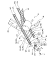
図2は、本実施態様のウエストパネル3(伸縮性シート)の製造方法に好適に用いられる製造装置を模式的に示したものである。
Next, the preferable embodiment of the manufacturing method of the elastic sheet of this invention is demonstrated, referring an example for the case where the waist panel 3 (elastic sheet) of the diaper 1 mentioned above is manufactured.
FIG. 2 schematically shows a production apparatus suitably used in the method for producing the waist panel 3 (elastic sheet) of this embodiment.

製造装置11は、図2に示すように、ウエストパネル3に使用される伸縮性シートを連続的に製造する装置であり、シートの搬送方向(y方向)と直交する方向(x方向)に離間した一対の搬送ベルト12,13に、糸状弾性体7を連続的に巻回する弾性体巻回用の回転アーム(弾性体巻回手段)14を備えている。また、製造装置11は、図2及び図3に示すように、糸状弾性体7を連続して繰り出し、回転アーム14に糸状弾性体7を伸長状態で導入する弾性体供給手段15と、前述の一対の搬送ベルト12,13により糸状弾性体7を一対の帯状シート50,60の間に搬送する搬送手段16と、一対のニップローラー171,172を用いて一対の帯状シート50,60の間に伸長状態の糸状弾性体7を固定する一体化手段17と、帯状シート50,60の幅方向両端部それぞれから延出している糸状弾性体7を切断する切断手段18とを備えている
本実施態様においては、一対の搬送ベルト12,13が、本発明における糸搬送用長手構造体であり、該糸搬送用長手構造体の長手方向は、両搬送ベルト12,13の延設方向(y方向)である。
As shown in FIG. 2, the manufacturing apparatus 11 is an apparatus that continuously manufactures an elastic sheet used for the waist panel 3, and is separated in a direction (x direction) orthogonal to the sheet conveyance direction (y direction). The pair of transport belts 12 and 13 is provided with a rotating arm (elastic body winding means) 14 for winding an elastic body for continuously winding the thread-like elastic body 7. Further, as shown in FIGS. 2 and 3, the manufacturing apparatus 11 continuously feeds the thread-like elastic body 7 and introduces the thread-like elastic body 7 into the rotating arm 14 in an extended state. A conveying means 16 that conveys the thread-like elastic body 7 between the pair of belt-like sheets 50 and 60 by the pair of conveyor belts 12 and 13 and a pair of nip rollers 171 and 172 between the pair of belt-like sheets 50 and 60. This embodiment includes an integration means 17 for fixing the elongated thread-like elastic body 7 and a cutting means 18 for cutting the thread-like elastic body 7 extending from both ends of the belt-like sheets 50 and 60 in the width direction. , The pair of conveyor belts 12 and 13 is the longitudinal structure for yarn conveyance in the present invention, and the longitudinal direction of the longitudinal structure for yarn conveyance is the extending direction of both the conveyor belts 12 and 13 (y direction). It is.

シートの搬送方向は、一対の搬送ベルト12,13に巻回された糸状弾性体7の搬送方向又はその糸状弾性体7と一体化されたシート(帯状シート50及び/又は60)の搬送方向である。
図2中矢印のy方向は、シートの搬送方向である、糸状弾性体7や一対の帯状シート50,60の搬送方向を示し、最終的に本実施態様により製造されるウエストパネル3(伸縮性シート)の搬送方向及び該ウエストパネル3(伸縮性シート)を取り付けたおむつ1の連続体の搬送方向とも同じ方向である。
また、図2中矢印のx方向は、帯状シート50,60の幅方向であり、シートの搬送方向と直交する方向である。また、図2中矢印のz方向は、後述する一対のニップローラー171,172どうしが対向する方向である。
The conveyance direction of the sheet is the conveyance direction of the thread-like elastic body 7 wound around the pair of conveyance belts 12 and 13 or the conveyance direction of the sheet integrated with the thread-like elastic body 7 (band-like sheets 50 and / or 60). is there.
The y direction of the arrow in FIG. 2 indicates the conveyance direction of the thread-like elastic body 7 and the pair of belt-like sheets 50 and 60, which is the sheet conveyance direction, and finally the waist panel 3 (stretchable) manufactured according to this embodiment. The conveying direction of the sheet) and the conveying direction of the continuous body of the diaper 1 to which the waist panel 3 (elastic sheet) is attached are the same direction.
Also, the x direction of the arrow in FIG. 2 is the width direction of the belt-like sheets 50 and 60, and is the direction orthogonal to the sheet conveying direction. 2 is a direction in which a pair of nip rollers 171 and 172 described later face each other.

搬送手段16の搬送ベルト12は、図2に示すように、無端状の回転ベルトであり、上下2段の上段搬送ベルト12aと下段搬送ベルト12bとからなる。上段搬送ベルト12aは、回転軸方向がz方向に配されたプーリー121,122間に架け渡されている。下段搬送ベルト12bは、回転軸方向がz方向に配されたプーリー124,125間に架け渡されている。プーリー121は、一対の帯状シート50,60の間に伸長状態の糸状弾性体7を固定する一対のニップローラー171,172の下流側に位置し、プーリー122は、ニップローラー171,172の上流側に位置している。プーリー124は、ニップローラー171,172よりも下流側に位置し、プーリー125は、ニップローラー171,172の上流側に位置している。プーリー121,124は、同じ位置に上下2段で配されている。また、ローラー122,125も、同じ位置に上下2段で配されている。また、プーリー121(プーリー124)及びプーリー122(プーリー125)は、帯状シート50,60のx方向端部よりもx方向外方に位置している。プーリー121及びプーリー124それぞれには、その駆動部にサーボモーター(不図示)が連設されており、上段搬送ベルト12a及び下段搬送ベルト12bそれぞれの回転速度を変更することができる。   As shown in FIG. 2, the conveyor belt 12 of the conveyor means 16 is an endless rotating belt, and includes an upper conveyor belt 12a and a lower conveyor belt 12b. The upper conveyance belt 12a is stretched between pulleys 121 and 122 whose rotation axis direction is arranged in the z direction. The lower conveyance belt 12b is bridged between pulleys 124 and 125 whose rotation axis direction is arranged in the z direction. The pulley 121 is located on the downstream side of the pair of nip rollers 171 and 172 for fixing the elongated thread-like elastic body 7 between the pair of belt-like sheets 50 and 60, and the pulley 122 is located on the upstream side of the nip rollers 171 and 172. Is located. The pulley 124 is located on the downstream side of the nip rollers 171 and 172, and the pulley 125 is located on the upstream side of the nip rollers 171 and 172. The pulleys 121 and 124 are arranged at the same position in two upper and lower stages. Further, the rollers 122 and 125 are also arranged in two upper and lower stages at the same position. Further, the pulley 121 (pulley 124) and the pulley 122 (pulley 125) are located outward in the x direction from the x direction end portions of the belt-like sheets 50 and 60. Each of the pulley 121 and the pulley 124 is provided with a servo motor (not shown) connected to its drive unit, so that the rotational speeds of the upper conveyance belt 12a and the lower conveyance belt 12b can be changed.

搬送手段16の搬送ベルト13は、図2に示すように、搬送ベルト12と同様に、無端状の回転ベルトであり、上下2段の上段搬送ベルト13aと下段搬送ベルト13bとからなる。上段搬送ベルト13aは、回転軸方向がz方向に配されたプーリー131,132間に架け渡されている。下段搬送ベルト13bは、回転軸方向がz方向に配されたプーリー134,135間に架け渡されている。プーリー131は、一対のニップローラー171,172の下流側に位置し、プーリー132は、ニップローラー171,172の上流側に位置している。プーリー134は、ニップローラー171,172よりも下流側に位置し、プーリー135は、ニップローラー171,172の上流側に位置している。プーリー131,134は、同じ位置に上下2段で配されている。また、プーリー132,135も、同じ位置に上下2段で配されている。また、プーリー131(プーリー134)及びプーリー132(プーリー135)は、帯状シート50,60のx方向端部よりもx方向外方に位置している。プーリー131及びプーリー134それぞれには、その駆動部にサーボモーター(不図示)が連設されており、上段搬送ベルト13a及び下段搬送ベルト13bそれぞれの回転速度を変更することができる。   As shown in FIG. 2, the conveyance belt 13 of the conveyance means 16 is an endless rotating belt, similar to the conveyance belt 12, and includes an upper conveyance belt 13a and a lower conveyance belt 13b. The upper conveyance belt 13a is stretched between pulleys 131 and 132 whose rotation axis direction is arranged in the z direction. The lower conveyance belt 13b is bridged between pulleys 134 and 135 whose rotation axis direction is arranged in the z direction. The pulley 131 is located on the downstream side of the pair of nip rollers 171 and 172, and the pulley 132 is located on the upstream side of the nip rollers 171 and 172. The pulley 134 is located on the downstream side of the nip rollers 171 and 172, and the pulley 135 is located on the upstream side of the nip rollers 171 and 172. The pulleys 131 and 134 are arranged in two upper and lower stages at the same position. Further, the pulleys 132 and 135 are also arranged in two upper and lower stages at the same position. Further, the pulley 131 (pulley 134) and the pulley 132 (pulley 135) are located outward in the x direction from the x direction ends of the belt-like sheets 50 and 60. Each of the pulley 131 and the pulley 134 is provided with a servo motor (not shown) connected to its drive unit, and the rotational speed of each of the upper conveyance belt 13a and the lower conveyance belt 13b can be changed.

図2に示すように、上述のように配されたプーリー121,122及びプーリー124,125に架け渡されることにより搬送ベルト12(上段搬送ベルト12a,下段搬送ベルト12b)は、一対のニップローラー171,172の上流側から下流側に亘って配される。また、上述のように配されたプーリー131,132及びプーリー134,135に架け渡されることにより搬送ベルト13(上段搬送ベルト13a,下段搬送ベルト13b)は、一対のニップローラー171,172の上流側から下流側に亘って配される。更に、搬送ベルト12(上段搬送ベルト12a,下段搬送ベルト12b)及び搬送ベルト13(上段搬送ベルト13a,下段搬送ベルト13b)は、帯状シート50,60のx方向外方に位置し、互いに左右対称に配されている。搬送ベルト12(上段搬送ベルト12a,下段搬送ベルト12b)及び搬送ベルト13(上段搬送ベルト13a,下段搬送ベルト13b)は、それぞれの外周側がy方向に移動するように回転する。
搬送ベルト12(上段搬送ベルト12a,下段搬送ベルト12b)及び搬送ベルト13(上段搬送ベルト13a,下段搬送ベルト13b)は、何れもタイミングベルトであることが好ましい。搬送ベルト12(上段搬送ベルト12a,下段搬送ベルト12b)及び搬送ベルト13(上段搬送ベルト13a,下段搬送ベルト13b)の回転速度、即ち、プーリー121及びプーリー124並びにプーリー131及びプーリー134それぞれの駆動部に配されたサーボモーター(不図示)の回転速度は、製造装置11の備える制御部(不図示)により、制御されている。
As shown in FIG. 2, the conveyor belt 12 (the upper conveyor belt 12 a and the lower conveyor belt 12 b) is bridged between the pulleys 121 and 122 and the pulleys 124 and 125 arranged as described above, and the pair of nip rollers 171. , 172 from the upstream side to the downstream side. Further, the conveyor belt 13 (the upper conveyor belt 13a and the lower conveyor belt 13b) is stretched over the pulleys 131 and 132 and the pulleys 134 and 135 arranged as described above, and the upstream side of the pair of nip rollers 171 and 172. To the downstream side. Further, the transport belt 12 (upper transport belt 12a and lower transport belt 12b) and the transport belt 13 (upper transport belt 13a and lower transport belt 13b) are located outside the belt-like sheets 50 and 60 in the x direction and are symmetrical with each other. It is arranged in. The transport belt 12 (upper transport belt 12a, lower transport belt 12b) and transport belt 13 (upper transport belt 13a, lower transport belt 13b) rotate so that their outer peripheral sides move in the y direction.
The transport belt 12 (upper transport belt 12a, lower transport belt 12b) and transport belt 13 (upper transport belt 13a, lower transport belt 13b) are preferably timing belts. The rotational speeds of the transport belt 12 (upper transport belt 12a, lower transport belt 12b) and transport belt 13 (upper transport belt 13a, lower transport belt 13b), that is, the driving units of the pulley 121 and pulley 124, and the pulley 131 and pulley 134, respectively. The rotation speed of a servo motor (not shown) arranged in the control unit is controlled by a control unit (not shown) included in the manufacturing apparatus 11.

回転アーム14は、図2に示すように、軸部142、周回部143及び連結部144を有するアーム部141と、軸部142の中心線を回転軸として、アーム部141を回転させる駆動機構147とを備えている。連結部144は、軸部142及び周回部143のそれぞれに対して角度をなして結合しており、周回部143と軸部142とは略平行となっている。軸部142は、その一端に糸状弾性体7の導入口145を有し、周回部143は、その一端に、糸状弾性体7の導出口146を有しており、導入口145から導入された糸状弾性体7が、軸部142、連結部144及び周回部143を通って導出口146からスムーズに導出される。アーム部141の屈曲部や導出口146等には、糸状弾性体7との間の摩擦を低減し得る各種公知の部材(従動ロールや低摩擦部材等)を配置することもできる。   As shown in FIG. 2, the rotating arm 14 includes an arm portion 141 having a shaft portion 142, a revolving portion 143, and a connecting portion 144, and a drive mechanism 147 that rotates the arm portion 141 around the center line of the shaft portion 142. And. The connecting portion 144 is coupled to each of the shaft portion 142 and the rotating portion 143 at an angle, and the rotating portion 143 and the shaft portion 142 are substantially parallel. The shaft portion 142 has an introduction port 145 for the thread-like elastic body 7 at one end thereof, and the circumferential portion 143 has a lead-out port 146 for the thread-like elastic body 7 at one end thereof, which is introduced from the introduction port 145. The thread-like elastic body 7 is smoothly led out from the outlet port 146 through the shaft portion 142, the connecting portion 144 and the rotating portion 143. Various known members (a driven roll, a low friction member, etc.) that can reduce friction with the thread-like elastic body 7 can be disposed in the bent portion of the arm portion 141, the outlet port 146, and the like.

周回部143は、導出口146の位置が、搬送ベルト12(上段搬送ベルト12a,下段搬送ベルト12b)及び搬送ベルト13(上段搬送ベルト13a,下段搬送ベルト13b)の上流側の端部より下流側に配されている。回転アーム14は、その駆動部(軸部142)にサーボモーター148が取り付けられており、該サーボモーター148の回転により、周回部143が、搬送ベルト12(上段搬送ベルト12a,下段搬送ベルト12b)及び搬送ベルト13(上段搬送ベルト13a,下段搬送ベルト13b)の外周を周回する。導出口146が回転する軌跡の直径は、一対の搬送ベルト12,13の外面間の距離より大きい。
このような回転アーム14により、取り込んだ糸状弾性体7を、搬送ベルト12(上段搬送ベルト12a,下段搬送ベルト12b)及び搬送ベルト13(上段搬送ベルト13a,下段搬送ベルト13b)の上流側の端部であって且つそれぞれの外周側に連続的に巻回することができる。回転アーム14の回転速度、即ち、サーボモーター148の回転速度は、製造装置11の備える制御部(不図示)により、制御されている。
In the circulation part 143, the position of the outlet 146 is downstream from the upstream end of the transport belt 12 (upper transport belt 12a, lower transport belt 12b) and transport belt 13 (upper transport belt 13a, lower transport belt 13b). It is arranged in. The rotary arm 14 has a servo motor 148 attached to its drive part (shaft part 142), and the rotation part 143 causes the rotation part 143 to move the conveyor belt 12 (the upper conveyor belt 12a and the lower conveyor belt 12b) by the rotation of the servo motor 148. And the outer circumference of the conveyor belt 13 (the upper conveyor belt 13a and the lower conveyor belt 13b) is circulated. The diameter of the locus along which the outlet 146 rotates is greater than the distance between the outer surfaces of the pair of conveyor belts 12 and 13.
By such a rotating arm 14, the thread-like elastic body 7 taken in is fed to the upstream end of the transport belt 12 (upper transport belt 12a, lower transport belt 12b) and transport belt 13 (upper transport belt 13a, lower transport belt 13b). It is a part and can be continuously wound on each outer peripheral side. The rotation speed of the rotary arm 14, that is, the rotation speed of the servo motor 148 is controlled by a control unit (not shown) included in the manufacturing apparatus 11.

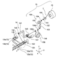
弾性体供給手段15は、図3に示すように、ボビン70から糸状弾性体7を引き出す手段と、ボビン70から引き出された糸状弾性体7に所定のテンションをかけるテンション調整手段15Aと、テンション調整手段15Aの下流側に位置して、テンション調整手段15Aから送り出された糸状弾性体7の速度を調整して、回転アーム(弾性体巻回手段)14に導入する速度調整手段15Bとを備えている。
テンション調整手段15Aは、ボビン70の下流側に位置して糸状弾性体7にブレーキによりテンションをかけるテンサー151と、テンサー151の下流側に位置する繰り出しローラー152と、繰り出しローラー152の下流側に位置するテンション測定器153とを備えている。繰り出しローラー152は、その回転軸方向がx方向に配されている。繰り出しローラー152には、その駆動部にサーボモーター(不図示)が取り付けられている。繰り出しローラー152は、その外周に糸状弾性体7が1回又は複数回(好ましくは2回)巻き付けられて使用される。本実施態様で用いた繰り出しローラー152は、前記の引き出し手段の全体又は一部を兼ねており、繰り出しローラー152によって、ボビン70から引き出された糸状弾性体7が、ガイド部材150のガイド孔を通ってテンサー151に導入される。
As shown in FIG. 3, the elastic body supply means 15 includes means for pulling out the thread-like elastic body 7 from the bobbin 70, tension adjusting means 15A for applying a predetermined tension to the thread-like elastic body 7 drawn out from the bobbin 70, and tension adjustment. A speed adjusting means 15B for adjusting the speed of the thread-like elastic body 7 fed from the tension adjusting means 15A and introducing it into the rotating arm (elastic body winding means) 14 is provided downstream of the means 15A. Yes.
The tension adjusting means 15 </ b> A is located on the downstream side of the bobbin 70, the tensioner 151 for applying tension to the thread-like elastic body 7 by the brake, the feeding roller 152 located on the downstream side of the tensor 151, and the downstream side of the feeding roller 152. And a tension measuring device 153. The feeding roller 152 has a rotational axis direction in the x direction. A servo motor (not shown) is attached to the driving portion of the feeding roller 152. The feeding roller 152 is used with the thread-like elastic body 7 wound around its outer periphery once or a plurality of times (preferably twice). The feeding roller 152 used in this embodiment also serves as the whole or a part of the above-mentioned drawing means, and the thread-like elastic body 7 drawn from the bobbin 70 by the drawing roller 152 passes through the guide hole of the guide member 150. Are introduced into the tensor 151.

テンション調整手段15Aは、テンション測定器153により、繰り出しローラー152とガイドローラー155との間の糸状弾性体7のテンションを検出し、製造装置11の備える制御部(不図示)により、テンション測定器153からの検出出力に基づき、繰り出しローラー152の回転速度をフィートバック制御する。これにより、ガイドローラー155から送り出される糸状弾性体7のテンションを、設定した所定のテンションに調整することができる。   The tension adjusting unit 15A detects the tension of the thread-like elastic body 7 between the feeding roller 152 and the guide roller 155 by the tension measuring device 153, and the tension measuring device 153 by a control unit (not shown) included in the manufacturing apparatus 11. The rotational speed of the feeding roller 152 is controlled by the foot back based on the detection output from the. Thereby, the tension of the thread-like elastic body 7 sent out from the guide roller 155 can be adjusted to the set predetermined tension.

速度調整手段15Bは、テンション調整手段15Aから送り出された糸状弾性体7の速度を調整し、その速度調整された糸状弾性体7を、回転アーム(弾性体巻回手段)14に導入する。速度調整手段15Bは、図3に示すように、回転アーム14の近傍に、フィードローラー156を備えている。フィードローラー156は、回転アーム14と繰り出しローラー152との間に配され、その回転軸方向がx方向に配されている。フィードローラー156の前後には、ガイドローラー156a,156bが配されている。フィードローラー156は、その駆動部にサーボモーター(不図示)が取り付けられている。サーボモーター(不図示)の回転速度、即ちフィードローラー156の回転速度は、製造装置11の備える制御部(不図示)により、制御されている。
フィードローラー156は、糸状弾性体の搬送経路において、回転アーム14の近傍、特に直前に配置されていることが好ましい。例えば、フィードローラー156を離れてから回転アーム14に導入されるまでの糸状弾性体の搬送経路の長さは、ボビン70から回転アーム14までの糸状弾性体の搬送経路の全長に対して、10〜50%であることが好ましく、より好ましくは10〜30%であることが好ましい。
The speed adjusting means 15B adjusts the speed of the thread-like elastic body 7 sent out from the tension adjusting means 15A, and introduces the speed-adjusted thread-like elastic body 7 into the rotating arm (elastic body winding means) 14. As shown in FIG. 3, the speed adjusting unit 15 </ b> B includes a feed roller 156 in the vicinity of the rotating arm 14. The feed roller 156 is disposed between the rotating arm 14 and the feeding roller 152, and the rotation axis direction thereof is disposed in the x direction. Guide rollers 156a and 156b are arranged before and after the feed roller 156. The feed roller 156 has a servo motor (not shown) attached to its drive unit. The rotation speed of the servo motor (not shown), that is, the rotation speed of the feed roller 156 is controlled by a control unit (not shown) provided in the manufacturing apparatus 11.
It is preferable that the feed roller 156 is disposed in the vicinity of the rotating arm 14, particularly immediately before the feed path of the thread-like elastic body. For example, the length of the conveyance path of the thread-like elastic body from the time when it leaves the feed roller 156 until it is introduced into the rotation arm 14 is 10 times the total length of the conveyance path of the thread-like elastic body from the bobbin 70 to the rotation arm 14. It is preferably ˜50%, more preferably 10 to 30%.

一体化手段17は、図2に示すように、一対のニップローラー171,172を備えている。一対のニップローラー171,172としては、金属製の円筒形のローラーや、低硬度シリコンゴム製の円筒形のローラーを用いることができる。一対のニップローラー171,172は、何れか一方の駆動部にサーボモーター(不図示)が取り付けられており、製造装置11が備える制御部(不図示)により回転速度が制御されている。一対のニップローラー171,172それぞれの回転軸には駆動伝達用のギヤが取り付けられている。この駆動手段(不図示)により、伸縮性シートの生産速度に基づき、サーボモーター(不図示)の回転速度、即ち一方のニップローラー171,172の回転速度をコントロールすることができる。その際、駆動伝達用のギヤが噛み合うことによって、他方のニップローラー172,171にも駆動力が伝達され、一対のニップローラー171,172を回転させることができる。一対のニップローラー171,172の軸受け部分は、一対の帯状シート50,60の間に伸長状態の糸状弾性体を確実に固定する為に、油圧、空圧、バネ等の力を利用して、それぞれの軸受け部分が加圧されている。   As shown in FIG. 2, the integration unit 17 includes a pair of nip rollers 171 and 172. As the pair of nip rollers 171, 172, a metal cylindrical roller or a cylindrical roller made of low hardness silicon rubber can be used. The pair of nip rollers 171 and 172 has a servo motor (not shown) attached to one of the drive units, and the rotation speed is controlled by a control unit (not shown) included in the manufacturing apparatus 11. Drive transmission gears are attached to the rotation shafts of the pair of nip rollers 171 and 172, respectively. By this driving means (not shown), the rotation speed of a servo motor (not shown), that is, the rotation speed of one of the nip rollers 171 and 172 can be controlled based on the production speed of the stretchable sheet. At this time, when the drive transmission gear is engaged, the driving force is transmitted to the other nip rollers 172 and 171, and the pair of nip rollers 171 and 172 can be rotated. The bearing portions of the pair of nip rollers 171 and 172 use a force such as hydraulic pressure, pneumatic pressure, or spring in order to securely fix the elongated elastic body between the pair of belt-like sheets 50 and 60, Each bearing part is pressurized.

一対のニップローラー171,172は、図2に示すように、搬送ベルト12(上段搬送ベルト12a,下段搬送ベルト12b)の内周側と搬送ベルト13(上段搬送ベルト13a,下段搬送ベルト13b)の内周側との間に位置している。   As shown in FIG. 2, the pair of nip rollers 171 and 172 includes an inner peripheral side of the transport belt 12 (upper transport belt 12a and lower transport belt 12b) and a transport belt 13 (upper transport belt 13a and lower transport belt 13b). It is located between the inner circumference side.

切断手段18は、図2に示すように、搬送されてくる糸状弾性体7が当たる部分が先鋭な切断刃となされたカッター180を備えている(搬送ベルト13側のカッター180は図示省略)。カッター180は、支持体(不図示)により、糸状弾性体7が当たる位置に配置されており、糸状弾性体7が、搬送ベルト12,13により搬送されてカッター180に押しつけられることにより切断される。切断手段18は、y方向においては、一対のニップローラー171,172と、搬送ベルト12(上段搬送ベルト12a,下段搬送ベルト12b)のプーリー121,124及び搬送ベルト13(上段搬送ベルト13a,下段搬送ベルト13b)のプーリー131,134との間に位置している。切断手段18により糸状弾性体7を切断するx方向の位置は、ニップローラー171,172と搬送ベルト12,13との間であっても良いし、搬送ベルト12,13それぞれの内周部と外周部との間であっても良いし、搬送ベルト12,13それぞれの外周部の外側であっても良い。また、切断手段18としては、糸状弾性体7を切断し得る各種公知のものを特に制限なく使用することができ、例えば、外周面に周方向に亘る切断刃を備えたカッターローラーと該切断刃を受けるアンビルローラーとを備えたローラーカッター等を用いることもできる。また、レーザーや熱等により切断してもよい。   As shown in FIG. 2, the cutting means 18 includes a cutter 180 in which a portion to which the conveyed elastic elastic body 7 contacts is a sharp cutting blade (the cutter 180 on the conveyance belt 13 side is not shown). The cutter 180 is disposed by a support (not shown) at a position where the thread-like elastic body 7 hits, and the thread-like elastic body 7 is cut by being conveyed by the conveyor belts 12 and 13 and being pressed against the cutter 180. . In the y direction, the cutting means 18 includes a pair of nip rollers 171, 172, pulleys 121, 124 of the conveyor belt 12 (upper conveyor belt 12a, lower conveyor belt 12b), and conveyor belt 13 (upper conveyor belt 13a, lower conveyor). It is located between the pulleys 131 and 134 of the belt 13b). The position in the x direction where the thread-like elastic body 7 is cut by the cutting means 18 may be between the nip rollers 171 and 172 and the conveyor belts 12 and 13, or the inner and outer circumferences of the conveyor belts 12 and 13, respectively. May be between the outer peripheral portions of the conveyor belts 12 and 13. As the cutting means 18, various known ones that can cut the thread-like elastic body 7 can be used without particular limitation. For example, a cutter roller having a cutting blade extending in the circumferential direction on the outer peripheral surface and the cutting blade It is also possible to use a roller cutter or the like equipped with an anvil roller for receiving the same. Moreover, you may cut | disconnect with a laser, a heat | fever, etc.

次に、上述した製造装置11を用いて伸縮性シートを製造する方法について説明する。   Next, a method for manufacturing a stretchable sheet using the manufacturing apparatus 11 described above will be described.

先ず、図3に示すように、糸状弾性体7を連続して繰り出し、繰り出された糸状弾性体7を伸長状態で弾性体巻回手段としての回転アーム14に導入する(供給工程)。供給工程においては、回転アーム14に導入する糸状弾性体7の導入速度を制御する。
詳述すると、繰り出しローラー152を用いて、ボビン70から糸状弾性体7を連続して引き出す。そして、ボビン70から引き出された糸状弾性体7にテンション調整手段15Aにより所定のテンションをかける。より具体的には、テンション測定器153により、繰り出しローラー152とガイドローラー155との間の糸状弾性体7のテンションを検出し、製造装置11の備える制御部(不図示)により、テンション測定器153からの検出出力に基づき、繰り出しローラー152の回転速度やテンサー151のブレーキを調整し、ガイドローラー155から下流側に向かって、所定のテンション(所定の伸長倍率)に調整された糸状弾性体7を送り出す。なお、テンサー151のブレーキは、ボビン70から引き出す際に生じることのある糸状弾性体の急激な弛みが下流工程に影響を与えないように設けてある。
First, as shown in FIG. 3, the thread-like elastic body 7 is continuously fed out, and the fed-out thread-like elastic body 7 is introduced into a rotating arm 14 as an elastic body winding means in a stretched state (supplying step). In the supply step, the introduction speed of the thread-like elastic body 7 introduced into the rotary arm 14 is controlled.
More specifically, the thread-like elastic body 7 is continuously pulled out from the bobbin 70 using the feeding roller 152. Then, a predetermined tension is applied to the thread-like elastic body 7 drawn out from the bobbin 70 by the tension adjusting means 15A. More specifically, the tension measuring device 153 detects the tension of the thread-like elastic body 7 between the feeding roller 152 and the guide roller 155, and the tension measuring device 153 is controlled by a control unit (not shown) included in the manufacturing apparatus 11. The rotational speed of the feeding roller 152 and the brake of the tensor 151 are adjusted on the basis of the detected output from the threaded elastic body 7 adjusted to a predetermined tension (predetermined expansion ratio) from the guide roller 155 toward the downstream side. Send it out. It should be noted that the brake of the tensor 151 is provided so that the sudden slack of the thread-like elastic body that may occur when the tensor 151 is pulled out from the bobbin 70 does not affect the downstream process.

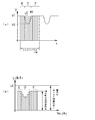
そして、その糸状弾性体7を回転アーム14に導入するのであるが、導入する際には、前述したテンション調整手段15Aにより、所定のテンション(所定の伸長倍率)に伸長された糸状弾性体7を、速度調整手段15Bにより、導入速度を制御しながら回転アーム14に供給する。製造装置11においては、回転アーム14の上流側に配したフィードローラー156により、糸状弾性体7の導入速度を制御する。具体的には、製造装置11においては、制御部(不図示)によりフィードローラー156の回転速度を制御し、図4(a)に示すように、ウエストパネル3の領域E(図1参照)に対応する部分に配される糸状弾性体7を導入速度V1で回転アーム14に導入し、ウエストパネル3の領域D(図1参照)に対応する部分に配される糸状弾性体7を導入速度V1よりも遅い導入速度V2で回転アーム14に導入し、ウエストパネル3の領域F(図1参照)に対応する部分に配される糸状弾性体7をウエストパネル3の領域B(図1参照)に配される糸状弾性体7の導入速度V1と同じ導入速度V1で回転アーム14に導入するように、糸状弾性体7の導入速度を制御する。以降は、導入速度V1、導入速度V2、導入速度V1の順を繰り返すように、フィードローラー156の回転速度を制御して、糸状弾性体7を回転アーム14に供給する。尚、図4(a)中のtDは、糸状弾性体7を回転アーム14(弾性体巻回手段)により一対の搬送ベルト12,13に半周巻回させるのに要する時間を示す。   Then, the thread-like elastic body 7 is introduced into the rotary arm 14. When the thread-like elastic body 7 is introduced, the thread-like elastic body 7 stretched to a predetermined tension (a predetermined stretching magnification) by the tension adjusting means 15A described above is introduced. The speed adjusting means 15B supplies the rotating arm 14 while controlling the introduction speed. In the manufacturing apparatus 11, the introduction speed of the thread-like elastic body 7 is controlled by a feed roller 156 arranged on the upstream side of the rotating arm 14. Specifically, in the manufacturing apparatus 11, the rotation speed of the feed roller 156 is controlled by a control unit (not shown), and as shown in FIG. 4A, in the region E (see FIG. 1) of the waist panel 3. The thread-like elastic body 7 disposed in the corresponding part is introduced into the rotary arm 14 at the introduction speed V1, and the thread-like elastic body 7 disposed in the part corresponding to the region D (see FIG. 1) of the waist panel 3 is introduced at the introduction speed V1. The thread-like elastic body 7 which is introduced into the rotary arm 14 at a slower introduction speed V2 and is arranged in a portion corresponding to the region F of the waist panel 3 (see FIG. 1) is placed in the region B of the waist panel 3 (see FIG. 1). The introduction speed of the thread-like elastic body 7 is controlled so that the thread-like elastic body 7 is introduced into the rotary arm 14 at the same introduction speed V1 as the introduction speed V1 of the arranged thread-like elastic body 7. Thereafter, the rotational speed of the feed roller 156 is controlled so as to repeat the order of the introduction speed V1, the introduction speed V2, and the introduction speed V1, and the thread-like elastic body 7 is supplied to the rotary arm 14. Note that tD in FIG. 4A indicates the time required for the thread-like elastic body 7 to be wound around the pair of transport belts 12 and 13 by the rotating arm 14 (elastic body winding means).

テンション調整手段15Aによりテンションを調整した糸状弾性体7の伸長倍率の好ましい範囲は、1.5〜4.0倍であり、より好ましくは1.8〜3.5倍である。
伸長倍率は下記の式で求められる。

伸長倍率=(伸ばされた糸状弾性体の長さ)÷(伸ばされていない糸状弾性体の長さ(糸状弾性体の自然長さ))
A preferable range of the expansion ratio of the thread-like elastic body 7 whose tension is adjusted by the tension adjusting means 15A is 1.5 to 4.0 times, more preferably 1.8 to 3.5 times.
The expansion ratio is obtained by the following formula.

Elongation magnification = (Length of stretched filamentous elastic body) ÷ (Length of unstretched filamentous elastic body (natural length of filamentous elastic body))

テンション調整手段15Aによりテンションを調整し、更に速度調整手段15Bのフィードローラー156の回転速度の制御によりテンションを調整した、製造する伸縮性シート(ウエストパネル3)における領域E、Fでの糸状弾性体7の伸長倍率の好ましい範囲は、1.5〜3.0倍であり、製造する伸縮性シート(ウエストパネル3)における領域Dでの糸状弾性体7の伸長倍率の好ましい範囲は、2.0〜4.0倍である。
伸長倍率は、テンション調整手段15Aや速度調整手段15Bでの糸状弾性体7の滑りなどを無視すれば、導入速度と回転アーム14の巻回速度との関係によって決まるため、伸長倍率と、所望の伸長倍率を得るための糸状弾性体の導入速度との関係は、下記の式で表される。

導入速度=(回転アーム14の巻回速度)÷(伸長倍率)×補正係数

尚、導入速度は、糸状弾性体7を回転アーム14に導入する速度であり、フィードローラー156の回転速度と同等であるから、下記の関係式に書き換えることができる。

フィードローラー156の回転速度
=(回転アーム14の巻回速度)÷(伸長倍率)×補正係数

つまり、回転アーム14の巻回速度を一定とした場合、糸状弾性体7の伸長倍率を高くするには、フィードローラー156の速度を遅くする、逆に、伸長倍率を低くするにはフィードローラー156の速度を速くすることで伸長倍率を制御することができる。
ここで、式中の補正係数は、所望の伸長倍率とフィードローラー156の速度と回転アーム14の速度の関係を表す比例係数であり、あらかじめ実験により求めることが出来る。例えば、回転アーム14の速度を一定とし、フィードローラー156の速度を変化させたときの糸状弾性体7の伸長倍率から回帰直線を求め、その回帰直線の傾きを補正係数とすることができる。
A thread-like elastic body in the regions E and F of the stretchable sheet (waist panel 3) to be manufactured, in which the tension is adjusted by the tension adjusting means 15A and the tension is adjusted by controlling the rotation speed of the feed roller 156 of the speed adjusting means 15B. The preferable range of the expansion ratio of 7 is 1.5 to 3.0, and the preferable range of the expansion ratio of the thread-like elastic body 7 in the region D in the stretchable sheet (waist panel 3) to be manufactured is 2.0. -4.0 times.
The extension magnification is determined by the relationship between the introduction speed and the winding speed of the rotating arm 14 if the slipping of the thread-like elastic body 7 by the tension adjustment means 15A and the speed adjustment means 15B is ignored. The relationship with the introduction speed of the filamentous elastic body for obtaining the expansion ratio is expressed by the following equation.

Introduction speed = (winding speed of the rotating arm 14) / (stretching magnification) × correction coefficient

The introduction speed is a speed at which the thread-like elastic body 7 is introduced into the rotary arm 14 and is equivalent to the rotation speed of the feed roller 156, and can be rewritten as the following relational expression.

Rotation speed of feed roller 156 = (winding speed of rotating arm 14) / (stretching magnification) × correction coefficient

That is, when the winding speed of the rotary arm 14 is constant, the speed of the feed roller 156 is decreased to increase the expansion ratio of the thread-like elastic body 7, and conversely, the feed roller 156 is decreased to decrease the expansion ratio. The stretching magnification can be controlled by increasing the speed.
Here, the correction coefficient in the equation is a proportional coefficient that represents the relationship between the desired expansion ratio, the speed of the feed roller 156, and the speed of the rotary arm 14, and can be obtained in advance by experiments. For example, it is possible to obtain a regression line from the expansion ratio of the filamentous elastic body 7 when the speed of the rotating arm 14 is constant and the speed of the feed roller 156 is changed, and the slope of the regression line can be used as a correction coefficient.

フィードローラー156の回転速度は、あらかじめ製造する伸縮性シート(ウエストパネル3)1枚分の速度パターンを決めておくことが望ましい。急激な速度の変化は、製造中の糸状弾性体7の切れに繋がり、安定した製造の阻害となるおそれがある。例えば、図4(a)のように、ウエストパネル3の領域E,Fに対応する部分ではフィードローラー156の回転速度を一定速度V1とし、伸長倍率を高くするウエストパネル3の領域Dに対応する部分では、回転速度を速度V1から速度V2へ徐々に遅くし、回転速度が速度V2に達したら、回転速度を速度V2から速度V1へ徐々に速度を上げる。このようにフィードローラー156の回転速度を変化させることにより、図4(b)のように、糸状弾性体7の導入量は、領域E,Fでは一定量であり、領域Dでは徐々に糸状弾性体7の導入量が少なくなった後に、糸状弾性体7の導入量が徐々に増えるため、糸状弾性体7の伸長倍率も同様に徐々に変化するようになり、製造中の糸状弾性体7の切れに繋がり難く、伸縮性シート(ウエストパネル3)を安定して製造することができる。ここで、「糸状弾性体7の導入量」とは、回転アーム(弾性体巻回手段)14によって1本の糸状弾性体7を巻きかける間(回転アーム14の半周に相当)に、ニップロール156で回転アーム14の導入口145に供給した糸状弾性体7の長さを意味する。   As for the rotational speed of the feed roller 156, it is desirable to determine a speed pattern for one elastic sheet (waist panel 3) to be manufactured in advance. An abrupt change in speed leads to breakage of the thread-like elastic body 7 being manufactured, which may hinder stable manufacture. For example, as shown in FIG. 4A, in the portion corresponding to the regions E and F of the waist panel 3, the rotation speed of the feed roller 156 is set to a constant speed V1, and the region corresponding to the region D of the waist panel 3 where the expansion magnification is increased. In the portion, the rotational speed is gradually decreased from the speed V1 to the speed V2, and when the rotational speed reaches the speed V2, the rotational speed is gradually increased from the speed V2 to the speed V1. By changing the rotation speed of the feed roller 156 in this way, the amount of introduction of the thread-like elastic body 7 is constant in the areas E and F as shown in FIG. Since the introduction amount of the thread-like elastic body 7 gradually increases after the introduction amount of the body 7 decreases, the expansion ratio of the thread-like elastic body 7 gradually changes in the same manner, and the thread-like elastic body 7 being manufactured is changed. The stretchable sheet (waist panel 3) is less likely to be cut and can be manufactured stably. Here, the “introduced amount of the thread-like elastic body 7” means that the nip roll 156 is wound while one thread-like elastic body 7 is wound by the rotating arm (elastic body winding means) 14 (corresponding to a half circumference of the rotating arm 14). This means the length of the thread-like elastic body 7 supplied to the inlet 145 of the rotary arm 14.

供給工程後には、図2,図3に示すように、回転アーム14を用いて伸長状態の糸状弾性体7を一対の搬送ベルト12,13に連続的に巻回し、巻回した糸状弾性体7を一対の搬送ベルト12,13の長手方向(y方向)に搬送する(搬送工程)。搬送工程における回転アーム14の回転速度は一定であることが好ましい。伸長状態で回転アーム14内に供給された糸状弾性体7は、導入口145から、アーム部141内に導入され、軸部142,連結部144及び周回部143内を通って、導出口146から導出される。導出口146から導出される糸状弾性体7は、回転アーム14が回転しながら導出されることによって、搬送ベルト12(上段搬送ベルト12a,下段搬送ベルト12b)の上流側の端部における外周側及び搬送ベルト13(上段搬送ベルト13a,下段搬送ベルト13b)の上流側の端部における外周側に巻回する。ここで、搬送ベルト12(上段搬送ベルト12a,下段搬送ベルト12b)及び搬送ベルト13(上段搬送ベルト13a,下段搬送ベルト13b)の回転走行により、搬送ベルト12(上段搬送ベルト12a,下段搬送ベルト12b)の外周側及び搬送ベルト13(上段搬送ベルト13a,下段搬送ベルト13b)の外周側に糸状弾性体7を連続的に螺旋状に巻きかけられる。この連続的に巻きかけられた糸状弾性体7を下流側の一対の帯状シート50,60の間に搬送する。   After the supplying step, as shown in FIGS. 2 and 3, the elongated thread-like elastic body 7 is continuously wound around the pair of conveying belts 12 and 13 using the rotating arm 14, and the wound thread-like elastic body 7 is wound. Is conveyed in the longitudinal direction (y direction) of the pair of conveying belts 12 and 13 (conveying step). It is preferable that the rotation speed of the rotary arm 14 in the transfer process is constant. The thread-like elastic body 7 supplied into the rotating arm 14 in the extended state is introduced from the introduction port 145 into the arm portion 141, passes through the shaft portion 142, the connecting portion 144, and the revolving portion 143, and from the outlet port 146. Derived. The thread-like elastic body 7 led out from the lead-out port 146 is led out while the rotary arm 14 is rotated, so that the outer peripheral side at the upstream end of the transport belt 12 (upper transport belt 12a, lower transport belt 12b) and The conveyor belt 13 (upper conveyor belt 13a, lower conveyor belt 13b) is wound around the outer peripheral side at the upstream end. Here, the conveyor belt 12 (upper conveyor belt 12a, lower conveyor belt 12b) and the conveyor belt 12 (upper conveyor belt 12a, lower conveyor belt 12b) are rotated by the rotational travel of the conveyor belt 12 (upper conveyor belt 12a, lower conveyor belt 12b). ) And the outer periphery of the conveyor belt 13 (upper conveyor belt 13a, lower conveyor belt 13b), the thread-like elastic body 7 is continuously wound in a spiral shape. The continuously wound thread-like elastic body 7 is conveyed between the pair of downstream belt-like sheets 50 and 60.

ここで、一対の搬送ベルト12,13に巻きかけられた糸状弾性体7は、y方向と交差する方向に伸長しており、y方向と直交する方向には配されていない。巻きかけられた糸状弾性体7をy方向と直交する方向(x方向)に修正するには、例えば、図2に示すように、糸状弾性体7が巻きかけられている場合には、搬送ベルト12においては、上段搬送ベルト12aの回転速度を下段搬送ベルト12bの回転速度よりも遅くし、搬送ベルト13においては、下段搬送ベルト13bの回転速度を上段搬送ベルト13aの回転速度よりも遅くすることにより、y方向への搬送中に糸状弾性体7の傾きを徐々に変化させ、一対の帯状シート50,60の間に搬送するまでに、糸状弾性体7の傾きをy方向と直交する方向(x方向)に修正することができる。   Here, the thread-like elastic body 7 wound around the pair of conveying belts 12 and 13 extends in a direction intersecting with the y direction, and is not arranged in a direction orthogonal to the y direction. In order to correct the wound elastic body 7 in a direction (x direction) orthogonal to the y direction, for example, when the elastic thread 7 is wound as shown in FIG. 12, the rotational speed of the upper transport belt 12 a is made slower than the rotational speed of the lower transport belt 12 b, and the rotational speed of the lower transport belt 13 b is made slower than the rotational speed of the upper transport belt 13 a in the transport belt 13. Thus, the inclination of the thread-like elastic body 7 is gradually changed during the conveyance in the y-direction, and the inclination of the thread-like elastic body 7 is orthogonal to the y-direction before being conveyed between the pair of belt-like sheets 50 and 60 ( x direction).

図2に示すように、帯状シート50は、予め、セーラー(不図示)等により、x方向の両端部それぞれが外面側に折られており、搬送ベルト12(上段搬送ベルト12a,下段搬送ベルト12b)及び搬送ベルト13(上段搬送ベルト13a,下段搬送ベルト13b)の上段側から一対のニップローラー171,172の間に供給されている。また、図2に示すように、帯状シート60は、予め、セーラー(不図示)等により、x方向の両端部それぞれが外面側に折られており、搬送ベルト12(上段搬送ベルト12a,下段搬送ベルト12b)及び搬送ベルト13(上段搬送ベルト13a,下段搬送ベルト13b)の下段側から一対のニップローラー171,172の間に供給されている。尚、帯状シート50及び/又は帯状シート60は、一対のニップローラー171,172の間に供給される前に、その内面側に接着剤が塗布されている。接着剤はストライプ状、スパイラル状、サイン波形状等に塗布されていてもよいし、全面にスプレーしたりベタ状に塗布されていてもよい。   As shown in FIG. 2, the belt-like sheet 50 is previously folded at both ends in the x direction on the outer surface side by a sailor (not shown) or the like, and the conveyor belt 12 (upper conveyor belt 12a, lower conveyor belt 12b). ) And the conveyor belt 13 (upper conveyor belt 13a, lower conveyor belt 13b) from the upper side of the nip rollers 171 and 172. In addition, as shown in FIG. 2, the belt-like sheet 60 is previously folded at both ends in the x-direction by a sailor (not shown) or the like, and is conveyed to the conveyor belt 12 (upper conveyor belt 12a, lower conveyor). The belt 12b) and the conveyor belt 13 (upper conveyor belt 13a, lower conveyor belt 13b) are supplied between a pair of nip rollers 171 and 172 from the lower side. In addition, before the strip | belt-shaped sheet 50 and / or the strip | belt-shaped sheet 60 are supplied between a pair of nip rollers 171,172, the adhesive agent is apply | coated to the inner surface side. The adhesive may be applied in a stripe shape, a spiral shape, a sine wave shape, or the like, or may be sprayed on the entire surface or applied in a solid shape.

次いで、ニップローラー171,172を用いて一対の帯状シート50,60の間に糸状弾性体7を伸長状態で固定する(一体化工程)。詳述すると、連続的に巻きかけられた糸状弾性体7が一対の帯状シート50,60の間に配された連続体を、一対のニップローラー171,172間に供給し、一対の帯状シート50,60の間に糸状弾性体7を伸長状態で固定する。   Next, the thread-like elastic body 7 is fixed in an extended state between the pair of belt-like sheets 50 and 60 using the nip rollers 171 and 172 (integration step). More specifically, a continuous body in which the continuously wound thread-like elastic body 7 is disposed between the pair of belt-like sheets 50 and 60 is supplied between the pair of nip rollers 171 and 172, and the pair of belt-like sheets 50. , 60 is fixed in a stretched state.

上述したように、一対の帯状シート50,60の間に固定された糸状弾性体7については、図4(b)に示すように、導入速度V2で回転アーム14に導入された領域Dの糸状弾性体7が、導入速度V1で回転アーム14に導入された領域E及び領域Fそれぞれの糸状弾性体7よりも弾性体の導入量が少なくなり、領域Dに配された糸状弾性体7の伸長倍率は、領域E及び領域Fそれぞれに配された糸状弾性体7の伸長倍率よりも高くなる。即ち、領域Dに配された糸状弾性体7の収縮力が、領域E及び領域Fそれぞれに配された糸状弾性体7の収縮力よりも強くなっている。尚、図1に示すウエストパネル3の平面図は略図であり、図1に示すウエストパネル3の各領域E,D,Fそれぞれに配された糸状弾性体7の本数と、図4(b)に示す各領域E,D,Fそれぞれの棒グラフの本数(糸状弾性体7の本数)とが図面上一致していないが、実際には、図1に示すウエストパネル3の領域Eには、図4(b)に示す領域Eの棒グラフの本数と同じ2本の糸状弾性体7が配され、図1に示すウエストパネル3の領域Dには、図4(b)に示す領域Dの棒グラフの本数と同じ7本の糸状弾性体7が配され、図1に示すウエストパネル3の領域Fには、図4(b)に示す領域Fの棒グラフの本数と同じ5本の糸状弾性体7が配されている。   As described above, with respect to the thread-like elastic body 7 fixed between the pair of belt-like sheets 50 and 60, as shown in FIG. 4 (b), the thread form in the region D introduced into the rotary arm 14 at the introduction speed V2. The elastic body 7 has less introduction amount of the elastic body than the thread-like elastic bodies 7 in the regions E and F introduced into the rotary arm 14 at the introduction speed V1, and the thread-like elastic body 7 disposed in the region D is elongated. The magnification is higher than the expansion magnification of the thread-like elastic body 7 disposed in each of the region E and the region F. That is, the contraction force of the thread-like elastic body 7 disposed in the region D is stronger than the contraction force of the thread-like elastic body 7 disposed in each of the region E and the region F. The plan view of the waist panel 3 shown in FIG. 1 is a schematic diagram, and the number of the thread-like elastic bodies 7 arranged in each region E, D, F of the waist panel 3 shown in FIG. The number of bar graphs (number of thread-like elastic bodies 7) in each of the regions E, D, and F shown in FIG. 1 does not match in the drawing, but actually, the region E of the waist panel 3 shown in FIG. Two thread-like elastic bodies 7 having the same number as the bar graph of the region E shown in FIG. 4B are arranged, and the region D of the waist panel 3 shown in FIG. 1 has the bar graph of the region D shown in FIG. Seven thread-like elastic bodies 7 equal to the number are arranged, and in the area F of the waist panel 3 shown in FIG. 1, five thread-like elastic bodies 7 that are the same as the number of bar graphs in the area F shown in FIG. It is arranged.

次いで、一対の帯状シート50,60の幅方向(x方向)両端部それぞれから延出している糸状弾性体7を前述したカッター180で切断する(切断工程)。   Next, the thread-like elastic body 7 extending from both ends in the width direction (x direction) of the pair of belt-like sheets 50 and 60 is cut by the cutter 180 described above (cutting step).

次いで、外面側に折られた帯状シート50,60それぞれのx方向の両端部を、セーラー(不図示)等により、折りを直して幅方向外方に拡げ、それぞれの拡げた部分同士を、接着剤や融着等の公知の接合手段により接合する。これにより、一対の帯状シート50,60の間に糸状弾性体7をy方向と交差する方向に伸長した状態に固定した帯状の伸縮性シートを連続的に製造することができる。この製造された帯状の伸縮性シートは、領域E、領域D、領域Fの順に形成されており、糸状弾性体7の伸長倍率が部分的に異なる帯状の伸縮性シートである。この帯状の伸縮性シートを、公知の切断手段(図示せず)により、間欠的にx方向に亘って切断する。間欠的に切断する間隔は、おむつ1の備えるウエストパネル3の寸法と同じである。これにより、図1に示すような、領域E、領域D、領域Fを有するウエストパネル3(伸縮性シート)を連続的に製造することができる。   Next, both ends in the x direction of each of the belt-like sheets 50 and 60 folded to the outer surface side are folded outwardly in the width direction by a sailor (not shown) or the like, and the widened portions are bonded to each other. It joins by well-known joining means, such as an agent and a melt | fusion. Thereby, the band-shaped elastic sheet which fixed the thread-like elastic body 7 in the direction which cross | intersected the y direction between a pair of band-shaped sheets 50 and 60 can be manufactured continuously. The manufactured belt-like stretchable sheet is formed in the order of the region E, the region D, and the region F, and is a belt-like stretchable sheet in which the expansion ratio of the thread-like elastic body 7 is partially different. This belt-like stretchable sheet is intermittently cut in the x direction by a known cutting means (not shown). The interval of intermittently cutting is the same as the size of the waist panel 3 provided in the diaper 1. Thereby, the waist panel 3 (elastic sheet) which has the area | region E, the area | region D, and the area | region F as shown in FIG. 1 can be manufactured continuously.

本発明の伸縮性シートの製造方法により製造される伸縮性シートは、最も多い糸状弾性体の伸長倍率(領域E及び領域Fに配された糸状弾性体7の伸長倍率)を基準伸長倍率とした際に、伸縮性シートを構成する全糸状弾性体(領域D,領域E及び領域Fに配された糸状弾性体7)における基準伸長倍率と異なる伸長倍率の糸状弾性体(領域Dに配された糸状弾性体7)の割合は、おむつ1に取り付けた際、領域Eに対応する腹部と領域Fに対応する部分の締め付け力を弱め、領域Dに対応する部分の締め付け力を強めることにより、おむつ1を装着した際のフィット性を向上させる観点から、10〜50%であることが好ましい。さらに伸長倍率の急激な変化により糸状弾性体7が切れることを防止して、製造を安定させる観点から、30〜50%であることが更に好ましい。   The stretchable sheet produced by the method for producing a stretchable sheet according to the present invention has the expansion ratio (extension ratio of the filamentous elastic body 7 arranged in the region E and the region F) of the most threadlike elastic body as the reference elongation ratio. In this case, the filamentous elastic body (disposed in the region D) having an expansion ratio different from the reference expansion ratio in the entire filamentous elastic body (the filamentous elastic body 7 disposed in the region D, the region E, and the region F) constituting the stretchable sheet. The ratio of the thread-like elastic body 7) is such that, when attached to the diaper 1, the tightening force of the part corresponding to the region D is weakened and the tightening force of the part corresponding to the region D is weakened. From the viewpoint of improving the fit when 1 is mounted, it is preferably 10 to 50%. Furthermore, it is more preferable that it is 30 to 50% from the viewpoint of preventing the filamentous elastic body 7 from being cut by a sudden change in the expansion ratio and stabilizing the production.

ウエストパネル3を備えるおむつ1の製造方法としては、公知の方法により、表面シート21の連続体、裏面シート22の連続体、及び両シート21,22の連続体間に、搬送方向(y方向)に間欠的に複数個の吸収体23,23・・・を配し、表面シート21の連続体の搬送方向(y方向)の両側部に伸長した複数本の弾性部材25及び立体ガード形成用シート24の連続体を配した吸収性本体2の連続体を別工程で製造する。
この製造された吸収性本体2の連続体を、搬送方向(y方向)に搬送しながら、x方向両外方に突出するように一対のウエストパネル3を、吸収性本体2の連続体に含まれる吸収体33毎に配したおむつ1の連続体を製造する。ここで、吸収性本体2の連続体の搬送方向(y方向)と、ウエストパネル3(伸縮性シート)を製造する際の搬送方向(y方向)は、同方向であり、ウエストパネル3(伸縮性シート)を90°反転する必要はない。その後、その連続体を、公知の切断手段(図示せず)により、個々のおむつ1の寸法に切断して、おむつ1を製造することができる。
As a manufacturing method of the diaper 1 provided with the waist panel 3, a conveyance direction (y direction) is performed between a continuous body of the top sheet 21, a continuous body of the back sheet 22, and a continuous body of both sheets 21, 22 by a known method. Are provided with a plurality of elastic members 25 and a three-dimensional guard forming sheet which are intermittently provided with a plurality of absorbers 23, 23... And extended on both sides in the conveying direction (y direction) of the continuous body of the topsheet 21. A continuous body of the absorbent main body 2 in which 24 continuous bodies are arranged is manufactured in a separate process.
A pair of waist panels 3 are included in the continuous body of the absorbent main body 2 so as to protrude outward in the x direction while transporting the manufactured continuous body of the absorbent main body 2 in the transport direction (y direction). The continuous body of the diaper 1 distribute | arranged for every absorber 33 to be manufactured is manufactured. Here, the conveyance direction (y direction) of the continuous body of the absorbent main body 2 and the conveyance direction (y direction) when manufacturing the waist panel 3 (elastic sheet) are the same direction, and the waist panel 3 (extension and contraction). It is not necessary to invert the adhesive sheet) by 90 °. Then, the diaper 1 can be manufactured by cutting the continuous body into dimensions of individual diapers 1 by a known cutting means (not shown).

本発明の伸縮性シートの製造方法は、上述の実施態様に何ら制限されるものではなく、適宜変更可能である。   The manufacturing method of the elastic sheet of this invention is not restrict | limited to the above-mentioned embodiment at all, and can be changed suitably.

例えば、製造装置11においては、回転アーム14の上流側に配した速度調整手段15Bの有するフィードローラー156により、糸状弾性体7の導入速度を制御しているが、速度調整手段15Bとしては、フィードローラー156に換えて、例えば、糸状弾性体7の上下に、空気圧等の力により互いに当接させたり離間させたりすることができる一対のニップロールを用いることができる。一対の該ニップロールを用いる場合について具体的に説明すると、領域E,Fに対応する部分においては、一対の前記ニップロールを離間させ、テンション調整手段15Aのみにより糸状弾性体7を回転アーム14の導入口145に導入速度V1で供給し、領域Dに対応する部分においては、テンション調整手段15Aによりテンションコントロールした糸状弾性体7を、一対の前記ニップロールで挟み、該ニップロールの回転速度を調整することにより、導入速度V2で回転アーム14の導入口145に供給する。   For example, in the manufacturing apparatus 11, the introduction speed of the filamentous elastic body 7 is controlled by the feed roller 156 of the speed adjusting unit 15B arranged on the upstream side of the rotary arm 14, but the speed adjusting unit 15B includes a feed roller 156. Instead of the roller 156, for example, a pair of nip rolls that can be brought into contact with or separated from each other by a force such as air pressure can be used above and below the thread-like elastic body 7. The case where a pair of the nip rolls are used will be described in detail. In a portion corresponding to the regions E and F, the pair of nip rolls are separated from each other, and the thread-like elastic body 7 is introduced into the inlet of the rotary arm 14 only by the tension adjusting means 15A. In the portion corresponding to the region D, the thread-like elastic body 7 tension-controlled by the tension adjusting means 15A is sandwiched between the pair of nip rolls, and the rotational speed of the nip rolls is adjusted. It is supplied to the inlet 145 of the rotary arm 14 at the introduction speed V2.

また、弾性体巻回手段としては、回転軸部分に糸状弾性体の導入部を有する円盤と該円盤からy方向の下流側に突出するアームとを有し、該アームが、搬送ベルト12,13の周囲を周回して、糸状弾性体を搬送ベルト12,13の周囲に巻回させるもの等を用いることもできる。
また、一対のニップロール170,171間に、幅方向両端部をそれぞれの外面側に折り返して細幅にした帯状シートを導入し、その帯状シート間に糸状弾性体を固定するのに代えて、一対のニップロール170,171間に、幅方向両端部が折り返していない帯状シートを導入し、その帯状シート間に糸状弾性体を固定しても良い。
The elastic body winding means includes a disk having a thread-like elastic body introducing portion at the rotating shaft portion and an arm protruding downstream from the disk in the y direction. It is also possible to use one that wraps around the belt and winds the elastic thread around the conveyor belts 12 and 13.
Further, instead of fixing a thread-like elastic body between the pair of nip rolls 170, 171 by introducing a band-like sheet having a narrow width by folding back both ends in the width direction to the respective outer surface sides. Between the nip rolls 170 and 171, a belt-like sheet whose both ends in the width direction are not folded back may be introduced, and the thread-like elastic body may be fixed between the belt-like sheets.

また、搬送ベルトとしては、一対の搬送ベルトではなく、WO2005/060910に開示のようなコンベアベルトを用いてもよい。この場合、用いられるコンベアベルトは1本でよい。また、糸搬送用長手構造体として、特開2002−192641号公報の図4〜6に記載されているスクリュー溝が設けられた糸支持部材を用いてもよい。   Further, as the conveyor belt, a conveyor belt as disclosed in WO 2005/060910 may be used instead of a pair of conveyor belts. In this case, only one conveyor belt may be used. Moreover, you may use the thread | yarn support member provided with the screw groove as described in FIGS. 4-6 of Unexamined-Japanese-Patent No. 2002-192641 as a longitudinal structure for thread | yarn conveyance.

また、糸状弾性体7は、その傾きをy方向と直交する方向(x方向)に修正したが、搬送ベルト12に巻きつけた角度のまま修正せずに一対の帯状シート50,60に固定してもよい。
また、図1では、一対のウエストパネル3,3を矩形状としたが、台形や平行四辺形としてもよい。伸縮性シートより、一対のウエストパネル3,3を切断して形成する際に、できるだけ廃棄する部分がない形状とすることが好ましい。
Further, the inclination of the thread-like elastic body 7 is corrected in the direction orthogonal to the y-direction (x-direction), but is fixed to the pair of belt-like sheets 50 and 60 without being corrected at the angle wound around the conveyor belt 12. May be.
Moreover, in FIG. 1, although a pair of waist panels 3 and 3 were made into the rectangular shape, it is good also as a trapezoid or a parallelogram. When the pair of waist panels 3 and 3 are cut and formed from the stretchable sheet, it is preferable to have a shape having as few portions as possible to be discarded.

上記実施態様の伸縮性シートの製造方法によれば、領域E、領域D、領域Fを有するウエストパネル3を製造するために、領域E及び領域Fに配される糸状弾性体7の伸長倍率と、領域Dに配される糸状弾性体7の伸長倍率との2種類の伸長倍率に分けているが、目的とする製造対象物に応じて糸状弾性体7の伸長倍率を複数箇所に分けることができる。   According to the elastic sheet manufacturing method of the above embodiment, in order to manufacture the waist panel 3 having the region E, the region D, and the region F, the expansion magnification of the thread-like elastic body 7 disposed in the region E and the region F and The elongation magnification of the thread-like elastic body 7 arranged in the region D is divided into two kinds of extension magnifications, but the extension magnification of the thread-like elastic body 7 can be divided into a plurality of locations according to the target manufacturing object. it can.

本発明の製造方法により製造される伸縮性シートは、使い捨ておむつ1のウエストパネル3以外に、パンツ型おむつの胴回り部、掃除用シート、包帯などにも使用することができる。   In addition to the waist panel 3 of the disposable diaper 1, the stretchable sheet produced by the production method of the present invention can be used for a waist part of a pant-type diaper, a cleaning sheet, a bandage, and the like.

1 展開型の使い捨ておむつ
2 吸収性本体
21 表面シート
22 裏面シート
23 吸収体
24 立体ガード形成用シート
25,26 弾性部材
3 ウエストパネル
3A ウエストパネルに使用される伸縮性シート
4 パネル材
5,6 シート
50,60 帯状のシート
7 糸状弾性体
70 ボビン
8 ファスニングテープ
11 製造装置
12 搬送ベルト(糸搬送用長手構造体の一部)
12a 上段搬送ベルト
121,122 プーリー
123 ローラー
112a,112b ローラー
114 ベルト
114a,114b ローラー
12b 下段搬送ベルト
124,125 プーリー
126 ローラー
122a,122b ローラー
115 ベルト
115a,115b ローラー
13 搬送ベルト(糸搬送用長手構造体の一部)
13a 上段搬送ベルト
131,132 プーリー
133 ローラー
13b 下段搬送ベルト
134,135 プーリー
136 ローラー
14 回転アーム
141,142,143 ガイド
15 供給手段
15A テンション調整手段
151 テンサー
152 繰り出しローラー
153 テンション測定器
15B 速度調整手段
156 フィードローラー
17 一体化手段
171,172 ニップローラー
173,174 矯正プレート
175 溝
176 カッター刃
178 溝
179 延出部
18 切断手段
180 カッター
A 腹側部,B 背側部,C 股下部
DESCRIPTION OF SYMBOLS 1 Unfoldable disposable diaper 2 Absorbent main body 21 Top sheet 22 Back sheet 23 Absorber 24 Three-dimensional guard forming sheet 25, 26 Elastic member 3 Waist panel 3A Elastic sheet used for waist panel 4 Panel materials 5, 6 Sheet 50, 60 Band-shaped sheet 7 Thread-like elastic body 70 Bobbin 8 Fastening tape 11 Manufacturing device 12 Conveying belt (part of the longitudinal structure for yarn conveyance)
12a Upper conveyor belt 121, 122 Pulley 123 Roller 112a, 112b Roller 114 Belt 114a, 114b Roller 12b Lower conveyor belt 124, 125 Pulley 126 Roller 122a, 122b Roller 115 Belt 115a, 115b Roller 13 Conveyor belt (long structure for yarn conveyance) Part of
13a Upper transport belt 131, 132 Pulley 133 Roller 13b Lower transport belt 134, 135 Pulley 136 Roller 14 Rotating arm 141, 142, 143 Guide 15 Supply means 15A Tension adjustment means 151 Tensor 152 Feeding roller 153 Tension measuring instrument 15B Speed adjustment means 156 Feed roller 17 Integral means 171, 172 Nip rollers 173, 174 Straightening plate 175 Groove 176 Cutter blade 178 Groove 179 Extension part 18 Cutting means 180 Cutter A Abdominal side, B Back side, C Inseam

Claims (3)

一対の帯状シートの間に糸状弾性体を該帯状シートの搬送方向と交差する方向に伸長した状態に固定した伸縮性シートを連続的に製造する伸縮性シートの製造方法であって、
前記糸状弾性体を連続して繰り出し、繰り出された該糸状弾性体を弾性体巻回手段に導入する供給工程と、該弾性体巻回手段を用いて前記糸状弾性体を、糸搬送用長手構造体に連続的に巻回し、巻回した該糸状弾性体を、該糸搬送用長手構造体の長手方向に搬送する搬送工程と、搬送した該糸状弾性体をシート間に挟んで固定する一体化工程とを備え、
前記供給工程においては、前記弾性体巻回手段に導入する前記糸状弾性体の導入速度を制御して、該糸状弾性体の伸長倍率が部分的に異なる伸縮性シートを製造する伸縮性シートの製造方法。
A method for producing a stretchable sheet for continuously producing a stretchable sheet fixed in a state in which a thread-like elastic body is stretched in a direction intersecting the transport direction of the beltlike sheet between a pair of beltlike sheets,
A feeding step of continuously feeding out the thread-like elastic body and introducing the fed-out thread-like elastic body into an elastic body winding means; and a longitudinal structure for transferring the thread-like elastic body using the elastic body winding means. Integration that continuously winds around the body, transports the wound thread-like elastic body in the longitudinal direction of the longitudinal structure for thread transportation, and fixes the transported thread-like elastic body between sheets A process,
In the supplying step, the elastic sheet is manufactured by controlling the introduction speed of the thread-like elastic body to be introduced into the elastic body winding means, and manufacturing a stretchable sheet having partially different elongation ratios of the thread-like elastic body. Method.
前記供給工程においては、前記弾性体巻回手段の上流側に配した速度調整手段により、前記糸状弾性体の導入速度を制御する請求項1に記載の伸縮性シートの製造方法。   2. The method for producing a stretchable sheet according to claim 1, wherein, in the supplying step, the introduction speed of the thread-like elastic body is controlled by speed adjusting means arranged on the upstream side of the elastic body winding means. 製造される前記伸縮性シートにおいて、最も多い前記糸状弾性体の伸長倍率を基準伸長倍率とした際に、該伸縮性シートを構成する全糸状弾性体における前記基準伸長倍率と異なる伸長倍率の糸状弾性体の割合が、10〜50%である請求項1又は2に記載の伸縮性シートの製造方法。   In the elastic sheet to be produced, when the elongation ratio of the most thread-like elastic body is the reference elongation ratio, the filament-like elasticity having an elongation ratio different from the reference elongation ratio of all the filamentous elastic bodies constituting the elastic sheet. The method for producing a stretchable sheet according to claim 1 or 2, wherein the proportion of the body is 10 to 50%.
JP2010271475A 2010-12-06 2010-12-06 Method for manufacturing stretchable sheet Pending JP2012120571A (en)

Priority Applications (1)

Application Number Priority Date Filing Date Title
JP2010271475A JP2012120571A (en) 2010-12-06 2010-12-06 Method for manufacturing stretchable sheet

Applications Claiming Priority (1)

Application Number Priority Date Filing Date Title
JP2010271475A JP2012120571A (en) 2010-12-06 2010-12-06 Method for manufacturing stretchable sheet

Publications (1)

Publication Number Publication Date
JP2012120571A true JP2012120571A (en) 2012-06-28

Family

ID=46502711

Family Applications (1)

Application Number Title Priority Date Filing Date
JP2010271475A Pending JP2012120571A (en) 2010-12-06 2010-12-06 Method for manufacturing stretchable sheet

Country Status (1)

Country Link
JP (1) JP2012120571A (en)

Cited By (3)

* Cited by examiner, † Cited by third party
Publication number Priority date Publication date Assignee Title
WO2014054565A1 (en) * 2012-10-05 2014-04-10 株式会社瑞光 Manufacturing method for stretch laminate and device
CN103908380A (en) * 2012-12-28 2014-07-09 尤妮佳股份有限公司 Manufacturing device for flexible sheet and manufacturing method for flexible sheet
US9278032B2 (en) 2011-11-30 2016-03-08 The Procter & Gamble Company Small-sized disposable pull-on diaper

Citations (8)

* Cited by examiner, † Cited by third party
Publication number Priority date Publication date Assignee Title
JPS63243309A (en) * 1986-06-30 1988-10-11 ト−ヨ−衛材株式会社 Method for adhering yarn or strip like elastomer in lateral direction of sheet under tension
JPH0970412A (en) * 1995-09-06 1997-03-18 Kyoto Seisakusho:Kk Curve gather controller for paper diaper
JP2009183364A (en) * 2008-02-04 2009-08-20 Uni Charm Corp Wearing article
WO2009145860A2 (en) * 2008-04-18 2009-12-03 Dsg Technology Holdings Ltd An elastic composite having cross-directional elasticity and a system and method for making the elastic composite
JP2010022549A (en) * 2008-07-18 2010-02-04 Daio Paper Corp Disposable diaper
JP2010022588A (en) * 2008-07-18 2010-02-04 Daio Paper Corp Tape type disposable diaper
JPWO2008078610A1 (en) * 2006-12-27 2010-04-22 ユニ・チャーム株式会社 Absorbent article and manufacturing method thereof
JP2011160933A (en) * 2010-02-08 2011-08-25 Oji Nepia Co Ltd Tape type disposable diaper

Patent Citations (8)

* Cited by examiner, † Cited by third party
Publication number Priority date Publication date Assignee Title
JPS63243309A (en) * 1986-06-30 1988-10-11 ト−ヨ−衛材株式会社 Method for adhering yarn or strip like elastomer in lateral direction of sheet under tension
JPH0970412A (en) * 1995-09-06 1997-03-18 Kyoto Seisakusho:Kk Curve gather controller for paper diaper
JPWO2008078610A1 (en) * 2006-12-27 2010-04-22 ユニ・チャーム株式会社 Absorbent article and manufacturing method thereof
JP2009183364A (en) * 2008-02-04 2009-08-20 Uni Charm Corp Wearing article
WO2009145860A2 (en) * 2008-04-18 2009-12-03 Dsg Technology Holdings Ltd An elastic composite having cross-directional elasticity and a system and method for making the elastic composite
JP2010022549A (en) * 2008-07-18 2010-02-04 Daio Paper Corp Disposable diaper
JP2010022588A (en) * 2008-07-18 2010-02-04 Daio Paper Corp Tape type disposable diaper
JP2011160933A (en) * 2010-02-08 2011-08-25 Oji Nepia Co Ltd Tape type disposable diaper

Cited By (9)

* Cited by examiner, † Cited by third party
Publication number Priority date Publication date Assignee Title
US9278032B2 (en) 2011-11-30 2016-03-08 The Procter & Gamble Company Small-sized disposable pull-on diaper
US9592163B2 (en) 2011-11-30 2017-03-14 The Procter & Gamble Company Disposable pull-on diaper
US10265221B2 (en) 2011-11-30 2019-04-23 The Procter & Gamble Company Disposable pull-on diaper
US11154432B2 (en) 2011-11-30 2021-10-26 The Procter & Gamble Company Disposable pull-on diaper
WO2014054565A1 (en) * 2012-10-05 2014-04-10 株式会社瑞光 Manufacturing method for stretch laminate and device
JPWO2014054565A1 (en) * 2012-10-05 2016-08-25 株式会社瑞光 Method and apparatus for manufacturing stretch laminate
CN103908380A (en) * 2012-12-28 2014-07-09 尤妮佳股份有限公司 Manufacturing device for flexible sheet and manufacturing method for flexible sheet
JP2014128435A (en) * 2012-12-28 2014-07-10 Uni Charm Corp Manufacturing apparatus for stretchable sheet, and manufacturing method for stretchable sheet
CN103908380B (en) * 2012-12-28 2018-10-26 尤妮佳股份有限公司 The manufacturing device of telescopic sheet and the manufacturing method of telescopic sheet

Similar Documents

Publication Publication Date Title
JP5089751B2 (en) Method for producing elastic sheet
JP5624868B2 (en) Method for manufacturing absorbent article
JP5390679B2 (en) Method for producing elastic sheet
JP5089758B2 (en) Elastic sheet manufacturing equipment
JP5089752B2 (en) Method for producing elastic sheet
WO2012057030A1 (en) Elastic sheet manufacturing method
JP2012120571A (en) Method for manufacturing stretchable sheet
JP5089761B2 (en) Method for producing elastic sheet
JP5909356B2 (en) Method for producing elastic sheet
JP5838027B2 (en) Method for producing elastic sheet
JP5806839B2 (en) Method for producing elastic sheet
JP5728213B2 (en) Elastic sheet manufacturing equipment
JP5746847B2 (en) Method for producing elastic sheet
TWI556800B (en) Apparatus for building
JP5759702B2 (en) Method for producing elastic sheet
JP5732243B2 (en) Method for producing elastic sheet
JP5775709B2 (en) Method for producing elastic sheet
JP5666493B2 (en) Absorbent article manufacturing equipment
JP2024081982A (en) Method and apparatus for producing stretchable sheet

Legal Events

Date Code Title Description
A621 Written request for application examination

Free format text: JAPANESE INTERMEDIATE CODE: A621

Effective date: 20131003

A977 Report on retrieval

Free format text: JAPANESE INTERMEDIATE CODE: A971007

Effective date: 20140709

A131 Notification of reasons for refusal

Free format text: JAPANESE INTERMEDIATE CODE: A131

Effective date: 20140819

A521 Written amendment

Free format text: JAPANESE INTERMEDIATE CODE: A523

Effective date: 20140910

A131 Notification of reasons for refusal

Free format text: JAPANESE INTERMEDIATE CODE: A131

Effective date: 20150324

A02 Decision of refusal

Free format text: JAPANESE INTERMEDIATE CODE: A02

Effective date: 20150714