WO2012056927A1 - 電力線通信システム - Google Patents
電力線通信システム Download PDFInfo
- Publication number
- WO2012056927A1 WO2012056927A1 PCT/JP2011/073820 JP2011073820W WO2012056927A1 WO 2012056927 A1 WO2012056927 A1 WO 2012056927A1 JP 2011073820 W JP2011073820 W JP 2011073820W WO 2012056927 A1 WO2012056927 A1 WO 2012056927A1
- Authority
- WO
- WIPO (PCT)
- Prior art keywords
- power line
- communication
- impulsive noise
- amplitude
- limiter
- Prior art date
- Legal status (The legal status is an assumption and is not a legal conclusion. Google has not performed a legal analysis and makes no representation as to the accuracy of the status listed.)
- Ceased
Links
Images







Classifications
-
- H—ELECTRICITY
- H04—ELECTRIC COMMUNICATION TECHNIQUE
- H04B—TRANSMISSION
- H04B3/00—Line transmission systems
- H04B3/02—Details
- H04B3/04—Control of transmission; Equalising
-
- H—ELECTRICITY
- H04—ELECTRIC COMMUNICATION TECHNIQUE
- H04B—TRANSMISSION
- H04B3/00—Line transmission systems
- H04B3/54—Systems for transmission via power distribution lines
- H04B3/542—Systems for transmission via power distribution lines the information being in digital form
-
- H—ELECTRICITY
- H04—ELECTRIC COMMUNICATION TECHNIQUE
- H04L—TRANSMISSION OF DIGITAL INFORMATION, e.g. TELEGRAPHIC COMMUNICATION
- H04L27/00—Modulated-carrier systems
- H04L27/18—Phase-modulated carrier systems, i.e. using phase-shift keying
- H04L27/20—Modulator circuits; Transmitter circuits
- H04L27/2032—Modulator circuits; Transmitter circuits for discrete phase modulation, e.g. in which the phase of the carrier is modulated in a nominally instantaneous manner
-
- H—ELECTRICITY
- H04—ELECTRIC COMMUNICATION TECHNIQUE
- H04B—TRANSMISSION
- H04B2203/00—Indexing scheme relating to line transmission systems
- H04B2203/54—Aspects of powerline communications not already covered by H04B3/54 and its subgroups
- H04B2203/5404—Methods of transmitting or receiving signals via power distribution lines
- H04B2203/5412—Methods of transmitting or receiving signals via power distribution lines by modofying wave form of the power source
-
- H—ELECTRICITY
- H04—ELECTRIC COMMUNICATION TECHNIQUE
- H04B—TRANSMISSION
- H04B2203/00—Indexing scheme relating to line transmission systems
- H04B2203/54—Aspects of powerline communications not already covered by H04B3/54 and its subgroups
- H04B2203/5429—Applications for powerline communications
- H04B2203/5445—Local network
-
- H—ELECTRICITY
- H04—ELECTRIC COMMUNICATION TECHNIQUE
- H04B—TRANSMISSION
- H04B2203/00—Indexing scheme relating to line transmission systems
- H04B2203/54—Aspects of powerline communications not already covered by H04B3/54 and its subgroups
- H04B2203/5429—Applications for powerline communications
- H04B2203/5458—Monitor sensor; Alarm systems
-
- H—ELECTRICITY
- H04—ELECTRIC COMMUNICATION TECHNIQUE
- H04B—TRANSMISSION
- H04B2203/00—Indexing scheme relating to line transmission systems
- H04B2203/54—Aspects of powerline communications not already covered by H04B3/54 and its subgroups
- H04B2203/5462—Systems for power line communications
- H04B2203/547—Systems for power line communications via DC power distribution
Definitions
- the present invention relates to a communication system including a plurality of communication devices.
- the present invention relates to a power line communication system capable of performing communication while reducing the influence of an impulsive noise suddenly generated from an actuator connected to the power line.
- the ECU Electronic Control Unit
- the ECU Electronic Control Unit
- Various functions are realized as a system by exchanging.
- vehicle control shifts from mechanical control to electrical control the functions of each ECU and functions realized by the system are increasing.
- the number and types of communication devices increase, and the number of communication lines (vehicle harnesses) connecting the communication devices also increases.
- PLC Power Communication
- in-vehicle LAN By applying the PLC to the in-vehicle LAN, it is possible to realize line saving and reduce the weight of the in-vehicle harness.
- the locking / unlocking of the electric door lock in the vehicle is performed according to the operation corresponding to the on / off operation of the switch of the driver or passenger, and communication is performed by turning on / off the door lock switch. Since impulsive noise is generated from a door lock actuator or the like connected to a power line as a medium, it is impossible to learn the temporal characteristics as described above.
- the present invention has been made in view of such circumstances, and a power line capable of performing communication while reducing the influence of impulsive noise suddenly generated from an actuator connected to the power line as a communication medium.
- An object is to provide a communication system.
- a power line communication system is a communication system in which a plurality of communication devices mounted on a vehicle communicate via a power line routed in the vehicle, and the amplitude of a signal propagating through the power line is predetermined.
- An amplitude limiter for limiting within an amplitude value is provided, and the plurality of communication devices modulate a data signal having a carrier frequency different from the frequency of the impulsive noise generated in the power line by phase shift keying. It is characterized by.
- a damped sine wave impulsive noise is generated on the power line serving as a transmission line, showing a high amplitude when it is generated and then decaying.
- This impulsive noise has a very high amplitude, and it takes about 10 ⁇ s at maximum from generation to attenuation. If the carrier frequency of the data signal is such that the symbol length of the data signal is sufficiently longer than the attenuated sine wave, the amplitude limiter can mitigate the influence of the large amplitude of the impulsive noise.
- LIN Local Interconnect Network
- a power line communication system is a communication system in which a plurality of communication devices mounted on a vehicle communicate via a power line routed in the vehicle, and the amplitude of a signal propagating through the power line is predetermined.
- An amplitude limiter for limiting within an amplitude value, and the plurality of communication devices modulate a data signal of a first carrier frequency by phase shift keying and perform low-speed communication via the power line.
- a plurality of second communication apparatuses that perform high-speed communication via the power line by modulating a data signal having a second carrier frequency different from the first carrier frequency by phase shift keying.
- the first carrier frequency is closer to the frequency of impulsive noise generated in the power line than the second carrier frequency, and the symbol length of the signal modulated by the first communication device is Wherein the longer than the length of the pulse noise.
- a common power line is used by a group of first communication devices that perform power line communication at a first carrier frequency and a group of second communication devices that perform power line communication at a second carrier frequency.
- a configuration for performing power line communication that is, a configuration for performing so-called multiplex communication.
- the first carrier frequency is close to the (peak) frequency of impulsive noise
- the carrier frequency is set so that the second carrier frequency is far from the frequency of the impulsive noise.
- the first carrier frequency may be the same as the frequency of the impulsive noise.
- the symbol length of the modulation signal of the first communication device is set longer than impulsive noise.
- the power line communication performed by the first communication device is the amplitude limiting effect of the impulsive noise by the amplitude limiter, even when the first carrier frequency is close to (or the same as) the frequency of the impulsive noise, and Since the symbol length is longer than the impulsive noise, normal communication can be performed without being affected by the impulsive noise.
- the first carrier frequency can be made close to the frequency of the impulsive noise
- the second carrier frequency used in the high-speed communication by the second communication device that may be affected by the impulsive noise is changed to the impulsive noise. It is possible to prevent the second communication device from being disturbed by impulsive noise.
- the phase shift keying is BPSK (Binary Phase Shift Shift Keying), and the plurality of communication devices receive a data signal by a synchronous detection method.
- BPSK Binary Phase Shift Shift Keying
- the phase shift keying is DBPSK (Differential Phase Shift Keying), and the plurality of communication devices receive a data signal by a delay detection method.
- the power line communication system is characterized in that the predetermined amplitude value is determined in advance based on characteristics of impulsive noise generated in the power line.
- the predetermined amplitude value limited by the amplitude limiter is determined by the characteristics of the impulsive noise estimated to be generated in the communication system, so that the influence of the impulsive noise can be more accurately removed. It becomes possible.
- the characteristics of impulsive noise generated in a power line serving as a transmission path may become significant depending on the circuit configuration. Therefore, it is possible to effectively remove the influence of noise characteristics according to the circuit configuration of the communication system, particularly the impulsive noise characteristics related to amplitude.
- the power line communication system according to the sixth invention is characterized in that the predetermined amplitude value is not more than twice the amplitude value of a signal transmitted and received between communication devices.
- the predetermined amplitude value limited by the amplitude limiter is set to be not more than twice the amplitude value of the signal transmitted / received between the communication devices (the signal modulated and superimposed on the power line).
- the inventor of the present application investigated the characteristics of impulsive noise generated in the power line of the vehicle, modeled this characteristic, and performed a simulation. In this simulation, when the amplitude value limited by the amplitude limiter is set to twice the amplitude value of the transmission / reception signal, the result of sufficiently reducing the influence of impulsive noise was obtained. For this reason, power line communication that is not affected by impulsive noise can be realized by limiting the amplitude to twice or less the amplitude value of the transmission / reception signal.
- the present invention it is possible to mitigate the influence of the impulsive noise that suddenly occurs on the power line, which is a communication medium, according to the characteristics of the impulsive noise by the existing method, and realize power line communication without any trouble. It becomes possible. In particular, if the characteristics of the impulsive noise from the source connected to the power line are remarkable, communication that avoids this is possible.
- FIG. 1 is a block diagram showing a configuration of an in-vehicle PLC system in the embodiment.
- the in-vehicle PLC system in the embodiment includes a plurality of ECUs 1, 1,... That are communication devices arranged in the vehicle, and a plurality of actuators 2, 2,.
- a power line 3 that transmits power to the ECU 1 and the actuator 2
- a power source 4 that supplies power to the ECUs 1, 1,..., And the actuators 2, 2, and so on
- a junction box for branching and relaying the power line 3 (J / B) 5 and a limiter 6 connected to the power line 3 are included.
- the ECUs 1, 1,... Are devices that use a microcomputer to receive power supply via a power supply circuit and control data transmission / reception by the PLC and operations of other components not shown.
- the ECUs 1, 1,... Operate as transmitters and receivers, respectively, and exchange data with each other.
- the ECUs 1, 1,... In the embodiment have the function of a LIN (Local Interconnect Network) controller, and the communication protocol between the ECUs 1, 1,.
- LIN Local Interconnect Network
- the power source 4 is an alternator that generates power using power from the engine or a battery that is stored by the alternator.
- the negative terminal is grounded, and the positive terminal is connected to the junction box 5 via the power line 3.
- the power supply 4 supplies a drive voltage of 12 V, for example, to each ECU 1, 1,.
- the junction box 5 includes a branch of the power line 3 and a relay circuit.
- a plurality of power lines 3, 3,... Are branched and connected to the junction box 5.
- the plurality of power lines 3, 3,... are connected to the ECUs 1, 1,.
- a switch is built in the ECU 1 so that the ON / OFF of the connection relay to the actuators 2, 2,... Is controlled by the ECU 1 that controls the actuators 2, 2,. When the switch is ON, power from the power source 4 is supplied to the actuator 2 so that the actuator 2 operates.
- Each of the ECUs 1, 1,... And the actuators 2, 2,... Is configured internally so that the connected power line 3 is connected (grounded) to the body ground via each configuration and load included in itself. Yes.
- each ECU 1, 1,... Operates not only by receiving power from the power source 4 via the power lines 3, 3,.
- Data for control is transmitted and received by superimposing a communication carrier wave.
- the power line 3 since the actuator 2 is connected to the power line 3 through which the ECUs 1, 1,... Perform data communication, the power line 3 generates event-driven impulsive noise.
- One of the actuators is, for example, a door lock motor that operates a lock of a vehicle door.
- the door lock motor rotates, for example, about 95 milliseconds, during which a large number of impulsive noises are generated in the power line.
- the main cause of impulsive noise is brush discharge of the motor, and after about 95 milliseconds, the frequency of occurrence of impulsive noise is sufficiently low.
- the carrier frequency of the communication signal is not impulsed but timed. It is necessary to select a communication method that is unlikely to be different from the frequency of noise and to be hardly affected.
- a modulation method of a communication carrier wave is defined and the limiter 6 is included.
- the configuration of the transceivers 11 and 12 and the configuration of the limiter 6 that the ECUs 1, 1,... And the result of having examined whether the communication which avoided the influence of impulsive noise is realizable with the said structure is demonstrated.
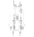
- FIG. 2 is a block diagram schematically showing a connection configuration of the transmitter 11 and the receiver 12 constituting the in-vehicle PLC system in the embodiment.
- a data signal output to transmit data to another ECU 1 by the function of the LIN controller is input to the transmitter 11 for performing communication in the PLC.
- the data signal received by the receiver 12 is notified to the processor constituting the ECU 1 by the function of the LIN controller, and transmission / reception using the power line 3 as the LIN bus becomes possible.
- the transmitter 11 includes a modulator 13 for transmitting a LIN data signal through the power line 3, a filter 14 for passing a signal in a predetermined band, and a sine wave output device (sine wave in the figure) 15.
- the receiver 12 includes a limiter 6, a sine wave output device 15, a filter 16, and a demodulation unit 17 that demodulates.
- the modulation unit 13 modulates and outputs a data signal input from other components in the ECU 1 using BPSK (Binary Phase Shift Keying) or DBPSK (Differential Binary Phase Shift Keying).
- BPSK Binary Phase Shift Keying
- DBPSK Different Binary Phase Shift Keying
- the frequency Fc of the carrier used for modulation can be 20 MHz or 10 MHz.
- the demodulator 17 demodulates the data signal from the carrier wave.
- the filter 14 and the filter 16 are root roll-off filters, and the roll-off rate is 0.5.
- the sine wave output unit 15 outputs a sine wave sin (2 ⁇ Fct) for multiplying the carrier wave.
- the transmitter 11 configured as described above modulates the data signal by the BPSK method or the DBPSK method, and the receiver 12 receives the data signal by the synchronous detection or the delay detection method (when the transmitter 11 performs the modulation of the BPSK method).
- the receiver 12 receives the data signal by the synchronous detection method, and when the transmitter 11 performs the DBPSK modulation, the receiver 12 receives the data signal by the delay detection method).
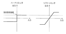
- FIG. 3 is a graph showing the input / output characteristics of the limiter 6 in the embodiment. Each of the two graphs shown in FIG. 3 shows the amplitude level of the signal input on the horizontal axis and the amplitude level of the signal output on the vertical axis. The right direction and the upward direction are positive, and the downward direction and the left direction are negative. is there.
- the limiter 6 in the embodiment has the characteristics of the hard limiter shown on the left in FIG. As shown in FIG. 3, the limiter 6 outputs with the amplitude of the received signal even if the amplitude of the input signal is larger than the amplitude of the received signal.
- the limiter 6 may have a soft limiter characteristic shown on the right side of FIG. In the case of a soft limiter, it is limited to twice the amplitude of the received signal. In this case, the limiter 6 outputs the input signal as it is up to twice the amplitude of the received signal, but outputs it at twice the amplitude of the received signal when it exceeds twice the amplitude of the received signal.
- limiter 6 may be arranged not only in front of the multiplier as shown in FIG. 2 but also between the multiplier and the filter 16 or between the filter 16 and the demodulator 17.
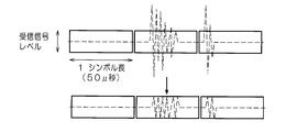
- FIG. 4 is an explanatory diagram conceptually showing the effect of mitigating the influence of impulsive noise by the limiter 6 constituting the in-vehicle PLC system in the embodiment.
- the waveform indicated by the broken line in FIG. 4 indicates impulsive noise, and the bold rectangle indicates the symbol length of one symbol of the data signal based on LIN, and the vertical indicates the amplitude value of the received signal.
- the waveform of impulsive noise after the amplitude is limited by the limiter 6 is shown.
- the maximum transmission capacity of LIN is 20 kbps (one symbol length is 50 ⁇ sec), and the symbol length is sufficiently long for one width showing a high amplitude of impulsive noise. Therefore, limiting the amplitude by the limiter 6 makes it possible to more effectively mitigate the influence on one symbol. Note that it is also possible to perform processing such as determining whether the signal level in each symbol is high or low at a sampling timing sufficiently shorter than the symbol length, and confirming more determination results as signal levels.
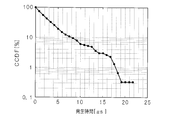
- FIG. 5 is a graph showing the measurement result of the impulsive noise generation time, which is the result of measuring the impulsive noise generation time actually generated in the power line 3 in the vehicle.
- the horizontal axis represents the generation time [ ⁇ s] of the impulsive noise
- the vertical axis represents the value [%] of the complementary cumulative distribution (CCDF (Complementary Cumulative Distribution Function)).
- CCDF complementary Cumulative Distribution Function
- the detected impulsive noise has an occurrence time of about 18 ⁇ sec or less (that is, impulsive noise of about 18 ⁇ sec or more is about 1% or less). Measurement results were obtained. From this, it can be seen that 50 ⁇ sec, which is the symbol length of LIN, is sufficiently longer than the generation time of impulsive noise generated in the vehicle. By setting the symbol length of the signal transmitted through the power line to be sufficiently longer than the generation time of the impulsive noise, the influence of the impulsive noise can be effectively mitigated.
- transceivers 11 and 12 are configured, and a signal transmitted from the transmitter 11 is transmitted through the power line 3. Since the power line 3 is connected to the plurality of actuators 2, 2,..., They serve as noise sources for the impulsive noise, and the impulsive noise is added to the carrier wave. Further, white gaussian noise (AWGN: Additive White Gaussian Noise) is added to the carrier wave at the inputs of the transceivers 11, 12 of the ECUs 1, 1,.
- AWGN Additive White Gaussian Noise
- the limiter 6 limits the amplitude to the amplitude of the received signal as shown in FIG. Thereby, the influence of impulsive noise is relieved.
- the carrier wave output from the limiter 6 reaches the multiplier inside the receiver 12.
- the multiplier inside the receiver 12 multiplies the arriving carrier wave by the sine wave from the sine wave output unit 15, passes through the filter 16, and then demodulates the demodulated signal in the ECU 1 as a data signal. Notify the processor.
- the transmitter 11 uses BPSK or DBPSK as the modulation method
- the receiver 12 demodulates using synchronous detection or delay detection
- the limiter 6 is connected to the power line 3 that is a transmission path, whereby LIN Can be realized by PLC.
- Whether or not communication avoiding the influence of impulsive noise can be realized depends on the BER when a predetermined impulsive noise is generated by simulation in the configuration including the transceivers 11 and 12 and the limiter 6 shown in FIG. Evaluate by Bit Error Rate).
- FIG. 6 is an explanatory diagram conceptually showing a method for creating noise used in the simulation.
- the hidden Markov Gaussian indicates whether the state of the noise obtained by measurement at each sampling timing is a state in which an impulsive noise is generated or a state in which it is not generated.
- An estimated state matrix in which the results estimated using the model and the BW-MAP method are arranged in time series is obtained.
- the frequency of the generated impulsive noise has peaks at 10 MHz and 30 MHz.
- the impulsive noise is generated using the estimated state matrix and the characteristics of the impulsive noise frequency and the like obtained thereafter.
- the waveform shown in the uppermost stage in FIG. 6 shows the estimated state matrix as a rectangular wave, one state of the length of one rectangular wave, and the length determined to generate impulses continuously.
- “0” is a state where no impulsive noise is generated (only white Gaussian noise)
- “1” is a state where impulsive noise is generated (mixing of impulsive noise and white Gaussian noise).
- FIG. 6 in the in-vehicle PLC, a state where impulsive noise is generated continues in a continuous section. This is because the impulsive noise generated in the in-vehicle PLC is an attenuated sine wave as shown in FIG.
- the section where the impulsive noise was generated (the section followed by “1”) was replaced with a window function having the same length as that section.
- the Hanning window was used as the window function.
- the window function W so that the impulse noise to be created also has peaks at two frequencies of 10 MHz and 30 MHz.
- W 2 (t) is obtained by multiplying 1 (t) by the sum of sine waves of two frequencies F 1 and F 2 (Equation 1).
- the phases of the two sine waves are ⁇ 1 and ⁇ 2 , respectively, and both take a random phase in the range of 0 to 2 ⁇ . This phase is determined randomly and independently for each detection section.
- the maximum value of the amplitude of the generated impulsive noise was matched with the measured amplitude of the impulsive noise in each section. That is, the function W 2 (t) whose amplitude is normalized to “1” is multiplied by the amplitude A (i) of the measured impulsive noise.
- a (i) in FIG. 6 is the absolute value of the maximum amplitude of impulsive noise which is the i-th measured attenuated sine wave.
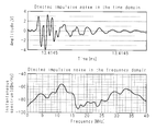
- FIG. 7 is a graph showing the characteristics of impulsive noise used in the simulation.
- the upper graph shows one impulsive noise waveform, and the lower graph shows frequency characteristics. Since the impulse noise of the generated noise uses a window function, it shows a symmetrical waveform that has a high amplitude at the center and attenuates as shown in the upper part of FIG. Further, as shown in the lower part of FIG. 7, the frequency of the created impulsive noise has peaks at 10 MHz and 30 MHz similarly to the actually measured impulsive noise.
- FIG. 8 is a graph showing the measurement result of the characteristics of the impulsive noise, and is a result of measuring the impulsive noise actually generated in the power line 3 in the vehicle.
- the waveform of one impulsive noise is shown in the upper part, and the frequency characteristic is shown in the lower part, which corresponds to the characteristic of the impulsive noise for simulation in FIG.
- the measured impulsive noise shows an attenuation waveform in which the amplitude gradually decreases and then changes gradually after a waveform that changes sharply with a high amplitude.
- the measured frequency of the impulsive noise has peaks at about 12 MHz and about 33 MHz as shown in the lower part of FIG.
- the noise including the impulsive noise created as shown in FIGS. 6 and 7 was generated in the power line 3 of the communication system having the configuration shown in FIG. 2, and the simulation of how much reception error occurred was executed.
- the simulation was performed a plurality of times while changing the carrier frequency to 5, 10, 15, 20, 25, and 30 MHz.
- the signal sampling frequency was 100 Mz.
- FIGS. 9 and 10 are graphs showing the characteristics of communication errors obtained by simulation.
- FIG. 9 shows the simulation results of the BPSK method + synchronous detection method (without the limiter 6), and FIG. 10 shows the DBPSK method + delay.
- the simulation result of the detection method (without the limiter 6) is shown.
- the horizontal axis represents signal power per bit versus background noise power E b / N 0 [dB], and the vertical axis represents BER.
- the BER is relatively good when the frequency of the carrier wave indicated by the symbol “x” is 20 MHz in both cases of the BPSK method and the DBPSK method.
- the frequency of the carrier wave is 10 MHz and 30 MHz, which is the same as the frequency of the impulsive noise, the BER is bad even in a region where E b / N 0 is high.
- E b / N 0 is set to about 60 [dB], so that either of the BPSK method and the DBPSK method can be used. It is estimated that the BER can be about 10 ⁇ 4 .
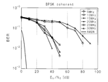
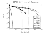
- FIG. 11 is a graph showing the characteristics of communication errors obtained by simulation, and shows both the simulation results of the BPSK method + synchronous detection method (with limiter 6) and the DBPSK method + delay detection method (with limiter 6).
- the BER when the carrier frequency is 20 MHz is low. Even when the carrier frequency is the same frequency as the impulsive noise, the improvement is made compared to the case without the limiter 6, but the BER is higher than the case of 20 MHz.
- E b / N 0 in the BPSK system is set to 11 [db It is estimated that the BER can be set to about 10 ⁇ 4 by setting E b / N 0 in the DBPSK system to about 13 [db].
- the limiter 6 improves E b / N 0 by about 50 [db].
- the BER can be suppressed to about 10 ⁇ 6 , which is practical. Therefore, an impulsive noise is obtained by a configuration in which modulation is performed by the BPSK method, reception is performed by the synchronous detection method, and the limiter 6 is used.
- the in-vehicle harness and the in-vehicle communication system in which the influence of the LIN communication cable is reduced and the LIN communication cable is saved can be realized.
- FIG. 9 to FIG. 11 show that impulsive noise is generated based on the window function of the Hanning window and used for the simulation as shown in FIG. This is because the impulsive noise generated in the in-vehicle PLC is an attenuated sine wave as shown in FIG.
- the inventor of the present application has found that the impulsive noise generated in the in-vehicle PLC can be approximated by an exponentially attenuated sine wave, and has re-verified by simulation using the impulsive noise as an exponentially attenuated sine wave.
- FIG. 12 is an explanatory diagram conceptually showing a method for creating noise used in the simulation.
- the section where the impulsive noise was generated (the section followed by “1”) was replaced with an envelope pulse having the same length as that section.
- the envelope pulse used an exponential decay function.
- the generated impulse noise since the frequency period of the impulsive noise has peaks at 10 MHz and 30 MHz, the generated impulse noise also has an envelope pulse P 1 (by an exponential decrement function so that it has peaks at two frequencies of 10 MHz and 30 MHz.
- P 2 (t) obtained by multiplying t) by the sum of sine waves of two frequencies F 1 and F 2 is obtained (Equation 2).
- the envelope pulse P 2 (t) whose amplitude is normalized to “1” is multiplied by the amplitude A (i) of the measured impulsive noise, and the receiver 12 White Gaussian noise corresponding to the characteristics was added as background noise to obtain noise used in the simulation.
- FIG. 13 is a graph showing the characteristics of the impulsive noise used in the simulation, and shows the characteristics of the impulsive noise created by the method shown in FIG.
- the upper graph shows one impulsive noise waveform
- the lower graph shows frequency characteristics.
- the amplitude of the created impulsive noise attenuates exponentially from the peak.
- the frequency of the created impulsive noise has peaks at 10 MHz and 30 MHz similarly to the actually measured impulsive noise.
- the characteristics of the impulse noise for simulation shown in FIG. 13 are closer to the characteristics of the measured impulse noise shown in FIG.
- the noise including the impulsive noise created as shown in FIG. 12 and FIG. 13 was generated in the power line 3 of the communication system having the configuration shown in FIG. 2, and the simulation of how much reception error occurred was executed.
- the simulation was performed when the carrier frequency was 10 MHz and 20 MHz.
- FIG. 14 is a graph showing the characteristics of the communication error obtained by the simulation.
- the simulation result of the BPSK method + synchronous detection method (without the limiter 6) (refer to BPSK-C indicated by the symbol “x” in the figure)
- a simulation result of DBPSK method + delay detection method (without limiter 6) (refer to DBPSK-D indicated by a symbol “ ⁇ ” in the figure).
- the BER is good when the frequency of the carrier wave shown by the broken line is 20 MHz
- the BER is bad when the frequency of the carrier wave shown by the solid line is 10 MHz. .
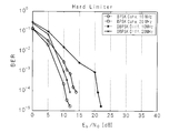
- FIG. 15 is a graph showing the characteristics of the communication error obtained by the simulation.
- the limiter 6 uses the hard limiter shown in FIG. 3 and limits the amplitude by the amplitude of the received signal.
- the BER is good when the frequency of the carrier wave shown by the broken line is 20 MHz, and the BER is bad when the frequency of the carrier wave shown by the solid line is 10 MHz. .
- the BER can be reduced to about 10 ⁇ 4 by setting E b / N 0 to about 55 [db]. is there.
- the limiter 6 shown in FIG. 15 if the carrier frequency is 20 MHz, the BER can be set to about 10 ⁇ 4 by setting E b / N 0 to about 11 [db]. Is possible. That is, by using the limiter 6 (hard limiter), E b / N 0 is improved by about 40 [db].
- FIG. 16 is a graph showing the characteristics of the communication error obtained by the simulation.
- the results are shown together.
- the limiter 6 uses the soft limiter shown in FIG. 3 and limits the amplitude at twice the amplitude of the received signal.
- the BER is good when the frequency of the carrier wave shown by the broken line is 20 MHz, and the BER is bad when the frequency of the carrier wave shown by the solid line is 10 MHz. .
- the BER can be set to about 10 ⁇ 4 by setting E b / N 0 to about 11 [db]. . That is, by using the limiter 6 (soft limiter), E b / N 0 is improved by about 40 [db].
- the communication quality required for the in-vehicle PLC system based on the LIN protocol is E b / N 0 of 60 [db] and BER of 10 ⁇ 4 or less. Therefore, when the frequency of the carrier wave is different from the frequency of the impulsive noise (for example, 20 MHz), by using the limiter 6, E b / N 0 is improved and the required communication quality can be sufficiently satisfied. .
- the limit amplitude by the limiter 6 is less than or equal to the amplitude of the received signal in the case of a hard limiter and less than twice the amplitude of the received signal in the case of a soft limiter, so that the required communication quality can be sufficiently satisfied. it can.
- E b / N 0 is improved by the above configuration, the output power of the communication signal output from the transmitter 11 can be reduced. Thereby, while being able to reduce the power consumption of the transmitter 11, the noise radiated
- FIG. 17 is a graph showing the characteristics of communication errors obtained by simulation, in which the horizontal axis is the communication speed (bit rate) [Mbit / s] and the vertical axis is the BER. Note that the simulation results are based on the configuration using the limiter 6 (hard limiter) while performing communication by the DBPSK method + delay detection method. The simulation was performed with the carrier frequency set to 10 MHz or 20 MHz and the signal E b / N 0 set to 20 dB, 40 dB, or 60 dB. In this simulation, when the carrier frequency is 10 MHz and E b / N 0 is 10 dB, an error occurs at a bit rate of 100 kbit / s and 200 kbit / s. In other cases, the bit rate is 100 kbit / s. Since no error occurred at 200 kbit / s, the simulation results are not plotted in the graph of FIG.
- the occurrence of errors can be reduced (the occurrence of errors) can be reduced by setting the bit rate to 200 kbit / s or less.
- the communication quality required for the in-vehicle PLC system based on the LIN protocol is E b / N 0 of 60 [db] and the BER is 10 ⁇ 4 or less, this configuration can sufficiently satisfy the communication quality.
- the communication speed of the LIN protocol is 20 kbit / s, and with this configuration, it is possible to realize a speed increase up to about 10 times the communication speed.
- the present invention is not limited to this, and can be applied to a communication system for controlling a load that may generate impulsive noise.
- FIG. 18 is a block diagram showing the configuration of the in-vehicle PLC system in the second embodiment.
- the in-vehicle PLC system according to the second embodiment is classified into two groups with respect to communication, and the first ECU 210a belonging to the first communication group and the second ECU 201b belonging to the second communication group have a common power line 3. And communicate via the power line 3.
- the first ECU 201a has the transmitter 11 and the receiver 12 shown in FIG. 2 and has substantially the same configuration as the ECU 1 of the first embodiment, but the frequency of the carrier wave used for modulation / demodulation of the data signal is Different.
- the frequency of the carrier wave (first carrier wave) used by the first ECU 201a according to the second embodiment is set to substantially the same frequency as the (peak) frequency of the impulsive noise generated in the power line 3, for example, 10 MHz.
- the symbol length of the signal transmitted and received by the first ECU 201a via the power line 3 is sufficiently longer than the impulsive noise (for example, 50 ⁇ sec) as shown in FIG.
- the first ECU 201 a Comparing the simulation results shown in FIGS. 14 and 15, even if the frequency of the carrier wave is 10 MHz, which is the same as the frequency of the impulsive noise, the first ECU 201 a includes the limiter 6, so that a sufficient improvement effect on the BER can be obtained. can get.
- the second ECU 201b includes the transmitter 11 and the receiver 12 shown in FIG. 2 (however, the configuration may not include the limiter 6), and has substantially the same configuration as the first ECU 201a. However, communication is performed at a higher speed than the first ECU 201a. That is, the symbol length of the signal transmitted and received by the second ECU 201b is shorter than that of the first ECU 201a (for example, 100 n seconds).
- the frequency of the carrier wave (second carrier wave) used by the second ECU 201b is set to a frequency different from the frequency of the impulsive noise generated in the power line 3, for example, 20 MHz.
- the first ECU 201a that performs low-speed power line communication uses the first carrier frequency close to the frequency of the impulsive noise, and the second ECU 201b that performs high-speed power line communication. Uses a second carrier frequency far from the frequency of the impulsive noise. Since the first ECU 201a has a long symbol length and is provided with the limiter 6, the carrier frequency of the first ECU 201a can be brought close to the frequency of the impulsive noise. The frequency band that can be used as the carrier frequency by the two ECUs 201b can be expanded. By making the carrier frequency of the second ECU 201b sufficiently away from the frequency of the impulsive noise, the influence of the impulsive noise on the power line communication by the second ECU 201b can be suppressed.
- the symbol length of the first ECU 201a is 50 ⁇ s
- the first carrier frequency is 10 MHz
- the symbol length of the second ECU 201b is 100 nsec
- the second carrier frequency is Although 20 MHz is set, these numerical values are merely examples, and the present invention is not limited thereto.
- the two communication groups are configured to communicate via the common power line 3
- the present invention is not limited to this, and three or more communication groups are configured to communicate via the common power line 3.
- the carrier frequency used in the communication group performing the slowest communication may be closest to the frequency of the impulsive noise.
Landscapes
- Engineering & Computer Science (AREA)
- Computer Networks & Wireless Communication (AREA)
- Signal Processing (AREA)
- Power Engineering (AREA)
- Cable Transmission Systems, Equalization Of Radio And Reduction Of Echo (AREA)
- Digital Transmission Methods That Use Modulated Carrier Waves (AREA)
Abstract
Description
これらによって、第1の通信装置が行う電力線通信は、第1の搬送周波数がインパルス性雑音の周波数に近い(又は同じ)場合であっても、振幅制限器によるインパルス性雑音の振幅制限効果、及び、シンボル長がインパルス性雑音より長いことにより、インパルス性雑音に影響されることなく正常な通信を行うことができる。また第1の搬送周波数をインパルス性雑音の周波数に近付けることができるため、インパルス性雑音の影響を受ける虞のある第2の通信装置による高速通信にて使用する第2の搬送波周波数をインパルス性雑音の周波数から遠ざけることができ、第2の通信装置の通信がインパルス性雑音により妨げられることを防止できる。
なお、以下に説明する実施の形態では、本発明を車両に搭載されるECU間の通信をPLCにて実現する車載PLCシステムに適用した例を挙げて説明する。
図1は、実施の形態における車載PLCシステムの構成を示すブロック図である。実施の形態における車載PLCシステムは、車両内に配される通信装置である複数のECU1,1,…と、各ECU1,1,…により制御されて作動する複数のアクチュエータ2,2,…と、ECU1及びアクチュエータ2へ電力を伝送する電力線3と、ECU1,1,…及びアクチュエータ2,2,…へ電力を供給する電源4と、電力線3の分岐及び中継のためのジャンクションボックス(図中J/B)5と、電力線3に接続されるリミッタ6とを含む。
図2に示すように送受信機11,12が構成され、送信機11から送信される信号は電力線3にて伝送される。電力線3には複数のアクチュエータ2,2,…が接続されているためにそれらがインパルス性雑音の雑音源となって搬送波にインパルス性雑音が加算される。また、各ECU1,1,…の送受信機11,12の入力には白色ガウス雑音(AWGN:Additive White Gaussian Noise)が搬送波に加算される。


図18は、実施の形態2における車載PLCシステムの構成を示すブロック図である。実施の形態2の車載PLCシステムは、通信に関して2つのグループに分類され、第1の通信グループに属する第1のECU210aと、第2の通信グループに属する第2のECU201bとが、共通の電力線3に接続され、この電力線3を介した通信をそれぞれ行っている。
2 アクチュエータ
3 電力線
6 リミッタ(振幅制限器)
Claims (6)
- 車両に搭載された複数の通信装置が、前記車両内に配索された電力線を介して通信を行なう通信システムにおいて、
前記電力線を伝播する信号の振幅を所定振幅値内に制限する振幅制限器を備え、
前記複数の通信装置は、前記電力線に発生するインパルス性雑音の周波数と異なる搬送波周波数のデータ信号を、位相偏移変調により変調するようにしてあること
を特徴とする電力線通信システム。 - 車両に搭載された複数の通信装置が、前記車両内に配索された電力線を介して通信を行なう通信システムにおいて、
前記電力線を伝播する信号の振幅を所定振幅値内に制限する振幅制限器を備え、
前記複数の通信装置には、
第1の搬送波周波数のデータ信号を、位相偏移変調により変調して前記電力線を介した低速通信を行う複数の第1の通信装置と、
前記第1の搬送波周波数とは異なる第2の搬送波周波数のデータ信号を、位相偏移変調により変調して前記電力線を介した高速通信を行う複数の第2の通信装置と
を含み、
前記第1の搬送周波数は、前記第2の搬送波周波数より、前記電力線に発生するインパルス性雑音の周波数に近く、
前記第1の通信装置が変調した信号のシンボル長は、前記インパルス性雑音の長さより長いこと
を特徴とする電力線通信システム。 - 前記位相偏移変調は、BPSK(Binary Phase Shift Keying)であり、
前記複数の通信装置は同期検波方式にてデータ信号を受信するようにしてあること
を特徴とする請求項1又は請求項2に記載の電力線通信システム。 - 前記位相偏移変調は、DBPSK(Differential Binary Phase Shift Keying)であり、
前記複数の通信装置は遅延検波方式にてデータ信号を受信するようにしてあること
を特徴とする請求項1又は請求項2に記載の電力線通信システム。 - 前記所定の振幅値は、前記電力線に発生するインパルス性雑音の特性に基づき予め定められてあること
を特徴とする請求項1乃至4のいずれかに記載の電力線通信システム。 - 前記所定の振幅値は、通信装置間で送受信する信号の振幅値の2倍以下であること
を特徴とする請求項1乃至請求項5のいずれかに記載の電力線通信システム。
Priority Applications (2)
| Application Number | Priority Date | Filing Date | Title |
|---|---|---|---|
| DE112011103594.2T DE112011103594B4 (de) | 2010-10-27 | 2011-10-17 | Netzleitungs-Kommunikationssystem |
| US13/877,916 US9048888B2 (en) | 2010-10-27 | 2011-10-17 | Power line communication system |
Applications Claiming Priority (4)
| Application Number | Priority Date | Filing Date | Title |
|---|---|---|---|
| JP2010-241328 | 2010-10-27 | ||
| JP2010241328 | 2010-10-27 | ||
| JP2011219520A JP2012109943A (ja) | 2010-10-27 | 2011-10-03 | 電力線通信システム |
| JP2011-219520 | 2011-10-03 |
Publications (1)
| Publication Number | Publication Date |
|---|---|
| WO2012056927A1 true WO2012056927A1 (ja) | 2012-05-03 |
Family
ID=45993642
Family Applications (1)
| Application Number | Title | Priority Date | Filing Date |
|---|---|---|---|
| PCT/JP2011/073820 Ceased WO2012056927A1 (ja) | 2010-10-27 | 2011-10-17 | 電力線通信システム |
Country Status (4)
| Country | Link |
|---|---|
| US (1) | US9048888B2 (ja) |
| JP (1) | JP2012109943A (ja) |
| DE (1) | DE112011103594B4 (ja) |
| WO (1) | WO2012056927A1 (ja) |
Cited By (1)
| Publication number | Priority date | Publication date | Assignee | Title |
|---|---|---|---|---|
| WO2017119054A1 (ja) * | 2016-01-04 | 2017-07-13 | 日立オートモティブシステムズ株式会社 | 電力線通信装置、および電力線通信装置を備えた電子制御装置 |
Families Citing this family (9)
| Publication number | Priority date | Publication date | Assignee | Title |
|---|---|---|---|---|
| US10474223B2 (en) * | 2014-12-31 | 2019-11-12 | Echelon Corporation | Systems, methods, and apparatuses for powerline communication |
| JP6319113B2 (ja) * | 2015-01-19 | 2018-05-09 | 株式会社デンソー | 電力制御装置 |
| JP6689158B2 (ja) * | 2016-08-04 | 2020-04-28 | 日立オートモティブシステムズ株式会社 | 電力線通信機能を備えた電子制御システムおよびそれを用いた自動車 |
| CN108964706B (zh) * | 2018-06-27 | 2022-03-11 | 广州视源电子科技股份有限公司 | 动力线信号传输方法、装置和传输用电设备 |
| CN108880621B (zh) * | 2018-09-11 | 2021-06-11 | 广东石油化工学院 | 一种电力线通信信号自适应滤波方法 |
| US20240204823A1 (en) * | 2021-05-04 | 2024-06-20 | Accelerated Systems Inc. | Methods and systems for operating an electric vehicle |
| US20230326270A1 (en) * | 2022-04-07 | 2023-10-12 | Snap-On Incorporated | Lockable Storage Devices |
| US12323198B2 (en) * | 2022-11-30 | 2025-06-03 | Bendix Commercial Vehicle Systems Llc | System and method for power line communication (PLC) signal data body encoding using differential phase detection |
| US20250140029A1 (en) * | 2023-10-31 | 2025-05-01 | Bendix Commercial Vehicle Systems Llc | Power Line Communication (PLC) Self-Test for Tractor-Trailers |
Citations (5)
| Publication number | Priority date | Publication date | Assignee | Title |
|---|---|---|---|---|
| JP2005531163A (ja) * | 2001-08-31 | 2005-10-13 | アダプチブ ネットワークス インコーポレーテッド | 広帯域通信を使用したデータ通信 |
| JP2006304086A (ja) * | 2005-04-22 | 2006-11-02 | Sumitomo Electric Ind Ltd | スイッチング電源、電力線搬送通信装置およびスイッチング電源制御方法 |
| JP2007228203A (ja) * | 2006-02-23 | 2007-09-06 | Ikuo Omura | 位相変調信号の復調装置 |
| JP2007258908A (ja) * | 2006-03-22 | 2007-10-04 | Sumitomo Electric Ind Ltd | 電力線通信装置、電力線通信ネットワークシステム、及び電力線通信方法 |
| JP2011135555A (ja) * | 2009-06-24 | 2011-07-07 | Kyoto Univ | 雑音検出方法、雑音検出装置、シミュレーション方法、シミュレーション装置、及び通信システム |
Family Cites Families (11)
| Publication number | Priority date | Publication date | Assignee | Title |
|---|---|---|---|---|
| US4379284A (en) * | 1979-09-21 | 1983-04-05 | Westinghouse Electric Corp. | Coherent phase shift keyed demodulator for power line communication systems |
| US4563650A (en) * | 1984-01-13 | 1986-01-07 | Westinghouse Electric Corp. | Power line communication receiver with dual threshold signal interrogation capability |
| US4645956A (en) * | 1984-09-11 | 1987-02-24 | Westinghouse Electric Corp. | Current limiter for power line communication amplifier |
| US7149252B2 (en) | 2001-08-31 | 2006-12-12 | Adaptive Networks, Inc. | Communicating data using wideband communications |
| KR100888661B1 (ko) * | 2002-06-20 | 2009-03-13 | 노키아 코포레이션 | 멀티 캐리어 신호를 수신하기 위한 방법 및 시스템 |
| JP2006067421A (ja) | 2004-08-30 | 2006-03-09 | Auto Network Gijutsu Kenkyusho:Kk | 信号送信装置、カメラ、コネクタ装置及び車載通信システム |
| CN101171153B (zh) * | 2005-05-11 | 2010-05-12 | 株式会社日立制作所 | 汽车及汽车内的通信与控制装置 |
| US7558337B2 (en) * | 2005-08-12 | 2009-07-07 | Ati Technologies, Inc. | Systems, methods, and apparatus for impulse noise mitigation |
| JP4487955B2 (ja) * | 2006-03-01 | 2010-06-23 | ソニー株式会社 | 無線通信装置及び方法 |
| US8520715B2 (en) * | 2006-07-06 | 2013-08-27 | Broadcom Corporation | Adaptative multi-carrier code division multiple access |
| FR2944171B1 (fr) | 2009-04-03 | 2012-12-21 | Get Enst | Procede et dispositif de modulation mettant en oeuvre une modulation differentielle, procede et dispositif de demodulation, signal et produits programme d'ordinateur correspondants. |
-
2011
- 2011-10-03 JP JP2011219520A patent/JP2012109943A/ja active Pending
- 2011-10-17 WO PCT/JP2011/073820 patent/WO2012056927A1/ja not_active Ceased
- 2011-10-17 DE DE112011103594.2T patent/DE112011103594B4/de not_active Expired - Fee Related
- 2011-10-17 US US13/877,916 patent/US9048888B2/en not_active Expired - Fee Related
Patent Citations (5)
| Publication number | Priority date | Publication date | Assignee | Title |
|---|---|---|---|---|
| JP2005531163A (ja) * | 2001-08-31 | 2005-10-13 | アダプチブ ネットワークス インコーポレーテッド | 広帯域通信を使用したデータ通信 |
| JP2006304086A (ja) * | 2005-04-22 | 2006-11-02 | Sumitomo Electric Ind Ltd | スイッチング電源、電力線搬送通信装置およびスイッチング電源制御方法 |
| JP2007228203A (ja) * | 2006-02-23 | 2007-09-06 | Ikuo Omura | 位相変調信号の復調装置 |
| JP2007258908A (ja) * | 2006-03-22 | 2007-10-04 | Sumitomo Electric Ind Ltd | 電力線通信装置、電力線通信ネットワークシステム、及び電力線通信方法 |
| JP2011135555A (ja) * | 2009-06-24 | 2011-07-07 | Kyoto Univ | 雑音検出方法、雑音検出装置、シミュレーション方法、シミュレーション装置、及び通信システム |
Non-Patent Citations (2)
| Title |
|---|
| CAETAN NDO ET AL.: "An Adaptive Procedure for Impulsive Noise Mitigation over Power Line Channels", IEEE GLOBAL TELECOMMUNICATIONS CONFERENCE, 2009., 30 November 2009 (2009-11-30), pages 1 - 6, XP031645709 * |
| YASUHIRO YABUUCHI ET AL.: "Measurement and analysis of impulsive noise on in-vehicle power lines", IEEE INTERNATIONAL SYMPOSIUM ON POWER LINE COMMUNICATIONS AND ITS APPLICATIONS (ISPLC), 2010, 28 March 2010 (2010-03-28), pages 325 - 330, XP031686449 * |
Cited By (3)
| Publication number | Priority date | Publication date | Assignee | Title |
|---|---|---|---|---|
| WO2017119054A1 (ja) * | 2016-01-04 | 2017-07-13 | 日立オートモティブシステムズ株式会社 | 電力線通信装置、および電力線通信装置を備えた電子制御装置 |
| JPWO2017119054A1 (ja) * | 2016-01-04 | 2018-08-02 | 日立オートモティブシステムズ株式会社 | 電力線通信装置、および電力線通信装置を備えた電子制御装置 |
| US10498395B2 (en) | 2016-01-04 | 2019-12-03 | Hitachi Automotive Systems, Ltd. | Power line communication apparatus and electronic control apparatus including power line communication apparatus |
Also Published As
| Publication number | Publication date |
|---|---|
| US9048888B2 (en) | 2015-06-02 |
| JP2012109943A (ja) | 2012-06-07 |
| DE112011103594T5 (de) | 2013-08-29 |
| DE112011103594B4 (de) | 2017-11-16 |
| US20130195208A1 (en) | 2013-08-01 |
Similar Documents
| Publication | Publication Date | Title |
|---|---|---|
| WO2012056927A1 (ja) | 電力線通信システム | |
| US11368330B2 (en) | Error frame detection | |
| CN106959439B (zh) | 汽车调频连续波雷达的强干扰抑制方法及系统 | |
| EP2790365A1 (en) | Communication device, communication system, and communication method | |
| JP3272875B2 (ja) | トランシーバ装置、通信方法および通信システム | |
| US10103780B1 (en) | Dual mode communication over automotive power lines | |
| JP2013542690A (ja) | 高速データレートによる直列データ伝送のための装置および方法 | |
| JP4952861B2 (ja) | 受信通信信号における干渉を低減するための装置と方法 | |
| JPWO2009145040A1 (ja) | 通信装置、通信システム、ワイヤハーネス及び通信方法 | |
| JP5223421B2 (ja) | 通信装置 | |
| EP1882613A1 (en) | Vehicle and in-vehicle communication control device | |
| CN104284422A (zh) | 利用自适应选择的载波频率的传感器系统和方法 | |
| Brandl et al. | Performance evaluation of a DQPSK and a DSSS PLC-modem for vehicular applications | |
| EP2897335B1 (en) | System and method for multi-dimensional modulation schemes with high noise immunity and low emission idle signaling for automotive area networks | |
| US12432102B2 (en) | Method and sensor bus system | |
| CN113075627A (zh) | 用于城市密集交通流条件下交通雷达抗干扰方法与装置 | |
| JP4375070B2 (ja) | 車両用変復調システム、受信装置および送信装置 | |
| US20250373343A1 (en) | Dynamic rfi suppression for communication protocols | |
| Kosuge et al. | 30.6 An electromagnetic clip connector for in-vehicle LAN to reduce wire harness weight by 30% | |
| EP4712355A1 (en) | A transceiver circuit and communications device | |
| Yabuuchi et al. | Low rate and high reliable modulation schemes for in-vehicle power line communications | |
| JPH0570348B2 (ja) | ||
| JP2006042173A (ja) | Ask通信装置 | |
| US10027430B1 (en) | Method and apparatus for estimating the current signal-to-thermal noise ratio and signal-to-pulse noise ratio | |
| JP2006237723A (ja) | 送信方法、送信装置及び通信システム |
Legal Events
| Date | Code | Title | Description |
|---|---|---|---|
| 121 | Ep: the epo has been informed by wipo that ep was designated in this application |
Ref document number: 11836063 Country of ref document: EP Kind code of ref document: A1 |
|
| WWE | Wipo information: entry into national phase |
Ref document number: 13877916 Country of ref document: US |
|
| WWE | Wipo information: entry into national phase |
Ref document number: 1120111035942 Country of ref document: DE Ref document number: 112011103594 Country of ref document: DE |
|
| 122 | Ep: pct application non-entry in european phase |
Ref document number: 11836063 Country of ref document: EP Kind code of ref document: A1 |