WO2012056926A1 - デジタル放送受信装置 - Google Patents
デジタル放送受信装置 Download PDFInfo
- Publication number
- WO2012056926A1 WO2012056926A1 PCT/JP2011/073818 JP2011073818W WO2012056926A1 WO 2012056926 A1 WO2012056926 A1 WO 2012056926A1 JP 2011073818 W JP2011073818 W JP 2011073818W WO 2012056926 A1 WO2012056926 A1 WO 2012056926A1
- Authority
- WO
- WIPO (PCT)
- Prior art keywords
- channel
- scan
- control unit
- unit
- broadcast
- Prior art date
- Legal status (The legal status is an assumption and is not a legal conclusion. Google has not performed a legal analysis and makes no representation as to the accuracy of the status listed.)
- Ceased
Links
Images




























Classifications
-
- H—ELECTRICITY
- H04—ELECTRIC COMMUNICATION TECHNIQUE
- H04L—TRANSMISSION OF DIGITAL INFORMATION, e.g. TELEGRAPHIC COMMUNICATION
- H04L27/00—Modulated-carrier systems
-
- H—ELECTRICITY
- H04—ELECTRIC COMMUNICATION TECHNIQUE
- H04N—PICTORIAL COMMUNICATION, e.g. TELEVISION
- H04N21/00—Selective content distribution, e.g. interactive television or video on demand [VOD]
- H04N21/40—Client devices specifically adapted for the reception of or interaction with content, e.g. set-top-box [STB]; Operations thereof
- H04N21/41—Structure of client; Structure of client peripherals
- H04N21/426—Internal components of the client ; Characteristics thereof
-
- H—ELECTRICITY
- H04—ELECTRIC COMMUNICATION TECHNIQUE
- H04N—PICTORIAL COMMUNICATION, e.g. TELEVISION
- H04N21/00—Selective content distribution, e.g. interactive television or video on demand [VOD]
- H04N21/40—Client devices specifically adapted for the reception of or interaction with content, e.g. set-top-box [STB]; Operations thereof
- H04N21/41—Structure of client; Structure of client peripherals
- H04N21/426—Internal components of the client ; Characteristics thereof
- H04N21/42607—Internal components of the client ; Characteristics thereof for processing the incoming bitstream
- H04N21/4263—Internal components of the client ; Characteristics thereof for processing the incoming bitstream involving specific tuning arrangements, e.g. two tuners
-
- H—ELECTRICITY
- H04—ELECTRIC COMMUNICATION TECHNIQUE
- H04N—PICTORIAL COMMUNICATION, e.g. TELEVISION
- H04N21/00—Selective content distribution, e.g. interactive television or video on demand [VOD]
- H04N21/40—Client devices specifically adapted for the reception of or interaction with content, e.g. set-top-box [STB]; Operations thereof
- H04N21/43—Processing of content or additional data, e.g. demultiplexing additional data from a digital video stream; Elementary client operations, e.g. monitoring of home network or synchronising decoder's clock; Client middleware
- H04N21/438—Interfacing the downstream path of the transmission network originating from a server, e.g. retrieving encoded video stream packets from an IP network
- H04N21/4383—Accessing a communication channel
-
- H—ELECTRICITY
- H04—ELECTRIC COMMUNICATION TECHNIQUE
- H04N—PICTORIAL COMMUNICATION, e.g. TELEVISION
- H04N5/00—Details of television systems
- H04N5/44—Receiver circuitry for the reception of television signals according to analogue transmission standards
- H04N5/46—Receiver circuitry for the reception of television signals according to analogue transmission standards for receiving on more than one standard at will
Definitions
- the present invention relates to a digital broadcast receiving apparatus.
- Broadcasting has been digitized in various countries, but in order to receive a digital broadcast by a receiving device that receives the digital broadcast, it is necessary to execute a channel scan in a frequency band allocated to the digital broadcast in advance.
- Patent Document 1 there is a technique described in Patent Document 1 as a technique for shortening the time required for channel scanning in a receiving apparatus that receives a digital broadcast.
- a technique described in Patent Document 1 in order to complete a channel scan in a short time, a plurality of front ends (tuners and demodulation units) are provided, a frequency band to be subjected to channel scan is divided, and each divided frequency band is divided into each front band.
- a receiving device is described in which the end performs channel scanning in parallel.
- DTMB Digital Terrestrial Multimedia Broadcast
- CMMB China Multimedia Mobile Broadcasting
- 12-segment broadcasting for fixed receivers and 1-segment broadcasting for mobile devices are performed according to the ISDB-T (Integrated Services Digital Broadcasting-Terrestrial) system.
- ISDB-T Integrated Services Digital Broadcasting-Terrestrial
- both 12-segment broadcasting and 1-segment broadcasting are multiplexed on one physical channel.
- the demodulation system is shared, and reception of 12-segment broadcasting and 1-segment broadcasting can be performed by one demodulation LSI.
- DTMB and CMMB in China are similar to 12-segment broadcasting and 1-segment broadcasting in ISDB-T in terms of broadcasting for fixed receivers and broadcasting for mobile devices, but different broadcasting methods and different demodulation processes . Therefore, dedicated LSIs are required for the DTMB and the CMMB as the demodulation LSIs. Also, for the streams obtained after demodulation, DTMB is in TS format, CMMB is in MF (Multiple Frame) format, and the filtering process for extracting video compression data and audio compression data from each stream is different from each other. The broadcast wave information that is the basis for generating the list is also different from each other.
- the DTMB digital broadcasting system and the CMMB digital broadcasting system are mixed in the same frequency band.
- physical channels are broadcast from 13 to 56 channels
- CMMB physical channels are broadcast from 13 to 48 channels.
- the center frequencies corresponding to the same physical channel number are exactly the same in DTMB and CMMB. Accordingly, only one of DTMB and CMMB is broadcast on the physical channel specified by the same physical channel number.
- DTMB DTMB will be briefly explained.
- TS in the physical channel
- broadcast wave information such as networks and services, program information, and the like are multiplexed in the TS.
- DTMB uses PSI and SI, and is very similar to the ISDB-T method and DVB-T method, such as a method of separating a video / audio compressed stream and a method of extracting PSI and SI. Therefore, the service list is generated from information obtained by extracting PSI and SI by channel scanning, as in ISDB-T.
- CMMB CMMB will be briefly described.
- a plurality of MFs are multiplexed in the physical channel, and in addition to the video / audio service data main body, broadcast wave information such as networks and services, program information, and the like are different from the DTMB system.
- This broadcast wave information is defined as CIT (Control Information Table) and is transmitted by a dedicated MF.
- the CIT transmits a network identification value, a network name, a transmission frequency, and the like using NIT (Network Information Table).
- NIT Network Information Table
- the CIT includes information for associating a service with an MF by MCT (Multiple Configuration Table). Then, the receiver extracts such CIT by channel scanning and generates a service list.
- MCT Multiple Configuration Table
- the DTMB method and the CMMB method are different in the front end processing in the tuner unit and the demodulation unit and the back end processing in which demultiplexing and decoding are performed. It is necessary to prepare a dedicated receiver compatible with
- a demodulator and demultiplexer for receiving the DTMB system
- a demodulator and demultiplexer for receiving the CMMB system. Since the multiplex units have different systems, they are generally configured separately.
- a DTMB reception mode and a CMMB reception mode are provided and received.
- the machine performs channel scanning of the broadcasting system corresponding to each mode.
- the receiving apparatus described in Patent Document 1 since the receiving apparatus described in Patent Document 1 is intended for a single broadcasting system, the receiving apparatus described in Patent Document 1 performs channel scanning for DTMB system broadcasting and CMMB system broadcasting.
- the time required for the DTMB channel scan is half that of the time required for the channel scan of the entire band by one front end. Can be.
- CMMB broadcasts are processed by two front ends corresponding to CMMB, the time required for CMMB channel scanning is halved compared to the time required for channel scanning of all bands by one front end.
- Patent Document 1 shortens the time required for channel scanning in a receiver that receives a broadcast by a single broadcast system, it is efficient for a broadcast of a plurality of broadcast systems. Therefore, it is not possible to shorten the time required for channel scanning.
- an object of the present invention is to provide a digital broadcast receiving apparatus that can efficiently perform channel scanning and reduce the time required for channel scanning when receiving broadcasts of a plurality of broadcasting systems.
- a digital broadcast receiving apparatus is a digital broadcast receiving apparatus that receives broadcasts of a first broadcast method and a second broadcast method in which at least a part of a frequency band to be used is overlapped.
- a first tuner for generating an electric signal from the first tuner, a first demodulator for demodulating an electric signal obtained from the first tuner to generate a first digital signal corresponding to the first broadcasting system, and the first
- a first demultiplexer for separating first data including channel selection information from one digital signal, the first tuner, the first demodulator, and the first demultiplexer to control the first data
- a first control unit that executes a channel scan of a broadcasting system, a second tuner that receives radio waves and generates an electrical signal from the radio waves, and demodulates an electrical signal obtained from the second tuner unit,
- a second demodulator for generating a second digital signal corresponding to the second broadcasting system; a second demultiplexer for separating second data including channel selection information from the second digital signal; and the second
- a second control unit that controls the second demodulating unit and the second demultiplexing unit to execute the channel scan of the second broadcasting system, and performs the first control as a channel scan of the first phase.
- the second control unit share a plurality of channels included in a frequency band in which the first broadcasting system and the second broadcasting system overlap, and perform a channel scan in parallel.
- the unit performs channel scan of the first broadcasting system in the channel scan of the first phase, and information indicating a reception state from the first tuner unit and the first demodulator unit 1 generates a first scan channel list indicating channels having a high possibility of the presence of broadcast waves other than the first broadcast method, and the second control unit performs the second broadcast method in the first phase channel scan.
- a channel scan is executed, and a second scan channel list indicating channels that are likely to contain broadcast waves other than the second broadcast system from information indicating reception states from the second tuner unit and the second demodulation unit.
- the first control unit performs a channel scan of the first broadcast system on the channels indicated in the second scan channel list, and the second control unit Performs channel scan of the second broadcast system for the channels indicated in the first scan channel list. It is characterized by doing.
- the channel scan when a broadcast of a plurality of broadcast systems is received, the channel scan can be efficiently performed and the time required for the channel scan can be shortened.
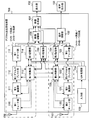
- FIG. 1 is a block diagram schematically showing a configuration of a digital broadcast receiving apparatus according to Embodiment 1.
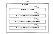
- FIG. 3 is a block diagram schematically showing a configuration of a first storage unit in the first embodiment.
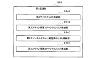
- FIG. 3 is a block diagram schematically showing a configuration of a second storage unit in the first embodiment.
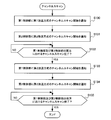
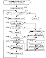
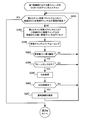
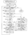
- 5 is a flowchart illustrating processing performed by a UIF processing unit when channel scanning is selected by a user operation in the first embodiment.
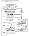
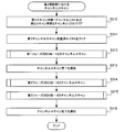
- 4 is a flowchart illustrating channel scan processing by the first control unit in the first embodiment.
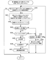
- 4 is a flowchart showing channel scan processing by a second control unit in the first embodiment.
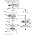
- 6 is a flowchart illustrating a first-phase DTMB channel scan subroutine performed by the first controller in the first embodiment.
- 5 is a flowchart illustrating a first-phase CMMB channel scan subroutine performed by the second control unit in the first embodiment.
- 5 is a flowchart illustrating a second-phase DTMB channel scan subroutine performed by the first controller in the first embodiment.
- 5 is a flowchart illustrating a second-phase CMMB channel scan subroutine performed by the second controller in the first embodiment.
- 6 is a flowchart illustrating a third-phase DTMB channel scan subroutine performed by the first controller in the first embodiment.
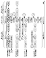
- 6 is a schematic diagram for explaining channel scanning performed by the digital broadcast receiving apparatus according to Embodiment 1.
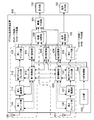
- FIG. 6 is a block diagram schematically showing a configuration of a digital broadcast receiving apparatus according to Embodiment 2.
- FIG. 1 is a block diagram schematically showing a configuration of a digital broadcast receiving apparatus according to Embodiment 2.
- FIG. 10 is a flowchart illustrating processing performed by a UIF processing unit when channel scanning is selected by a user operation in the second embodiment.
- FIG. 9 is a block diagram schematically showing a configuration of a digital broadcast receiving apparatus according to a third embodiment.
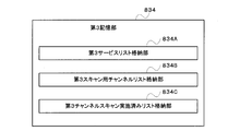
- 10 is a block diagram schematically showing a configuration of a first storage unit in Embodiment 3.
- FIG. 10 is a block diagram schematically showing a configuration of a second storage unit in the third embodiment.
- 14 is a flowchart illustrating processing performed by a UIF processing unit when channel scanning is selected by a user operation in the third embodiment.
- FIG. 10 is a schematic diagram for explaining channel scanning performed by the digital broadcast receiving device according to the third embodiment.
- FIG. 10 is a block diagram schematically showing a configuration of a digital broadcast receiving apparatus according to a fourth embodiment.
- FIG. 10 is a block diagram schematically showing a configuration of a digital broadcast receiving apparatus according to a fifth embodiment.
- FIG. 16 is a block diagram schematically showing a configuration of a first storage unit in the fifth embodiment.
- FIG. 16 is a block diagram schematically showing a configuration of a second storage unit in the fifth embodiment.
- FIG. 10 is a block diagram schematically showing a configuration of a digital broadcast receiving apparatus according to a sixth embodiment.
- FIG. 25 is a block diagram schematically showing a configuration of a first storage unit in the sixth embodiment.
- FIG. 25 is a block diagram schematically showing a configuration of a third storage unit in the sixth embodiment.
- FIG. 25 is a block diagram schematically showing a configuration of a second storage unit in the sixth embodiment.
- 18 is a flowchart illustrating processing performed by the UIF processing unit when channel scanning is selected by a user operation in the sixth embodiment.
- 18 is a flowchart showing channel scan processing by the first control unit in the sixth embodiment.
- 18 is a flowchart showing channel scan processing by a second control unit in the sixth embodiment.
- 22 is a flowchart illustrating a first-phase DVB-T channel scan subroutine performed by the first controller in the sixth embodiment.
- 18 is a flowchart illustrating a first-phase DVB-H channel scan subroutine performed by a second control unit according to the sixth embodiment.
- 22 is a flowchart illustrating a second-phase DVB-T channel scan subroutine performed by the first controller in the sixth embodiment.
- 22 is a flowchart illustrating a second-phase DVB-H channel scan subroutine performed by the second control unit in the sixth embodiment.
- 18 is a flowchart illustrating a third-phase DVB-T channel scan subroutine performed by the first controller in the sixth embodiment.
- 22 is a flowchart illustrating a third-phase DVB-H channel scan subroutine performed by the second controller in the sixth embodiment.
- FIG. 38 is a flowchart (No. 1) illustrating a fourth-phase DVB-T2 channel scan subroutine performed by the first controller in the sixth embodiment.
- FIG. FIG. 29 is a flowchart (No.
- FIG. 10 is a schematic diagram for explaining channel scanning performed by a digital broadcast receiving device according to a sixth embodiment.
- FIG. 10 is a block diagram schematically showing a configuration of a digital broadcast receiving apparatus according to a seventh embodiment.
- FIG. 25 is a block diagram schematically showing a configuration of a first storage unit in the seventh embodiment.
- FIG. 25 is a block diagram schematically showing a configuration of a second storage unit in the seventh embodiment.
- FIG. 25 is a block diagram schematically showing a configuration of a third storage unit in the seventh embodiment.
- 24 is a flowchart illustrating processing performed by the UIF processing unit when channel scanning is selected by a user operation in the seventh embodiment.
- 18 is a flowchart showing channel scan processing by the first control unit in the seventh embodiment.
- 18 is a flowchart showing channel scan processing by a second control unit in the seventh embodiment.
- FIG. 25 is a flowchart showing a first-phase DVB-T2 channel scan subroutine performed by the first controller in the seventh embodiment.
- FIG. 25 is a flowchart illustrating a first-phase DVB-T2 channel scan subroutine performed by the second controller in the seventh embodiment.
- FIG. 24 is a flowchart illustrating a second-phase DVB-T channel scan subroutine performed by the first controller in the seventh embodiment.
- 28 is a flowchart illustrating a second-phase DVB-H channel scan subroutine performed by the second controller in the seventh embodiment.
- FIG. 25 is a flowchart illustrating a third-phase DVB-T channel scan subroutine performed by the first controller in the seventh embodiment.
- 28 is a flowchart illustrating a third-phase DVB-H channel scan subroutine performed by the second controller in the seventh embodiment.
- FIG. 10 is a schematic diagram for explaining channel scanning performed by a digital broadcast receiving device according to a seventh embodiment.
- FIG. 10 is a schematic diagram for explaining channel scanning performed by a digital broadcast receiving device according to an eighth embodiment.
- FIG. 20 is a block diagram schematically showing a configuration of a first storage unit in an eighth embodiment.
- FIG. 25 is a block diagram schematically showing a configuration of a second storage unit in the eighth embodiment.
- FIG. 25 is a block diagram schematically showing a configuration of a third storage unit in the eighth embodiment.
- FIG. 25 is a block diagram schematically showing a configuration of a fourth storage unit in the eighth embodiment.
- 29 is a flowchart illustrating processing performed by the UIF processing unit when channel scanning is selected by a user operation in the eighth embodiment.
- 20 is a flowchart showing channel scan processing by the first control unit in the eighth embodiment.
- 29 is a flowchart illustrating channel scan processing by the second control unit in the eighth embodiment.
- FIG. 10 is a schematic diagram for explaining channel scanning performed by a digital broadcast receiving device according to an eighth embodiment.
- 40 is a flowchart illustrating processing performed by a UIF processing unit when channel scanning is selected by a user operation in the ninth embodiment.
- FIG. 38 is a flowchart showing channel scan processing by the first controller in the ninth embodiment.
- 30 is a flowchart showing channel scan processing by the second control unit in the ninth embodiment.
- FIG. 20 is a schematic diagram for explaining channel scanning performed by the digital broadcast receiving device according to the ninth embodiment.
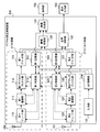
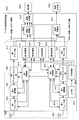
- FIG. 1 is a block diagram schematically showing the configuration of the digital broadcast receiving apparatus 100 according to the first embodiment.
- the digital broadcast receiving apparatus 100 includes a first tuner unit 110, a first demodulation unit 111, a first demultiplexing unit 112, a first decoding unit 113, and a first storage unit 114.
- the first antenna 150 is connected to the first tuner unit 110.
- the first antenna 150, the first tuner unit 110, the first demodulation unit 111, the first demultiplexing unit 112, the first decoding unit 113, the first storage unit 114, and the first control unit 115 are used as the first broadcasting system.
- a DTMB system that receives DTMB broadcasts is configured.
- the second tuner unit 120 is connected to the second antenna 151.
- the second antenna 151, the second tuner unit 120, the second demodulation unit 121, the second demultiplexing unit 122, the second decoding unit 123, the second storage unit 124, and the second control unit 125 are used as the second broadcasting system.
- a CMMB system that receives CMMB broadcasts is configured.
- the first tuner unit 110 receives a radio wave via the first antenna 150, generates an electrical signal based on the radio wave, and supplies the electric signal to the first demodulator 111.
- the first tuner unit 110 tunes to the frequency of the physical channel designated by the instruction from the first control unit 115 during the channel scan, and determines the reception level determination result of the radio wave received on the physical channel as the first result. Notify the control unit 115.
- the first demodulator 111 performs demodulation processing on the electrical signal supplied from the first tuner unit 110, generates a first digital signal, and supplies the first digital signal to the first demultiplexer 112.
- the format of the first digital signal differs depending on the broadcasting system.
- the first demodulator 111 outputs a DTMB TS as the first digital signal.
- the first demodulation unit 111 performs a demodulation process on the electrical signal supplied from the first tuner unit 110 during the channel scan, and displays the result of whether or not the frame can be locked as the first control unit. 115 is notified.
- the first tuner 150 and the first demodulator 111 have a plurality of first antennas 150, and perform diversity processing on radio waves received via these antennas and output one TS. Also good.
- the first demultiplexing unit 112 separates the compressed video data and audio compression data of a specific service from the demodulated first digital signal, and supplies the separated data to the first decoding unit 113. Further, the first demultiplexer 112 separates the first data in which the channel selection information is stored from the demodulated first digital signal, and gives the separated data to the first controller 115. Here, the first demultiplexing unit 112 filters and separates the PSI and SI as the first data, and provides them to the first control unit 115.
- the first decoding unit 113 decodes the video compression data and the audio compression data given from the first demultiplexing unit 112.
- the first decoding unit 113 provides the decoded video signal to the video switching unit 130 and provides the decoded audio signal to the audio switching unit 132.
- the first storage unit 114 stores information necessary for scanning the channels of the first broadcasting system and the second broadcasting system, and information necessary for receiving a service broadcast in the first broadcasting system.
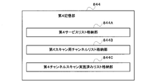
- FIG. 2 is a block diagram schematically showing the configuration of the first storage unit 114. As shown in FIG. 2, the first storage unit 114 includes a first service list storage unit 114A, a first scan channel list storage unit 114B, and a first channel scan completed list storage unit 114C.
- the first service list storage unit 114A stores a list of channel selection information necessary for receiving a service broadcast in the first broadcasting system.
- the first service list storage unit 114A stores a first service list having channel selection information including network information, TS information, and service information extracted by the first control unit 115 for each channel.
- the first scan channel list storage unit 114B receives the electric signal generated from the radio wave in the first scan, although the reception power of the radio wave received by the first tuner unit 110 is larger than a predetermined threshold during the channel scan.
- a first scan channel list which is a list of identification information (here, channel numbers) for identifying physical channels that could not be demodulated by the demodulation unit 111 (cannot be frame-locked), is stored.
- the reception power of radio waves received on a physical channel that has been subjected to DTMB channel scan, which is the first broadcast system can stably view the CMMB service, which is the second broadcast system.
- the second threshold (B) is a value obtained using the following equation (1).
- B [dBm] C / N [dB] + 10 log (kTW) + receiver noise figure [dB] ...
- 10 log (kTW) is a thermal noise figure
- the bottom of the log is 10.
- the bit error rate after decoding the LDPC code which is the inner code
- the bit error rate after decoding the LDPC code is 3 ⁇ 10 ⁇ 6 or less
- the CMMB service can be viewed stably.
- the C / N (required C / N) at this time varies depending on the modulation scheme in which the CMMB service is transmitted and the coding rate of the LDPC code.
- C / N in equation (1) is When the modulation scheme employed in CMMB is QPSK and the LDPC coding rate is 1/2, it is 2.7 dB.
- the modulation scheme employed in CMMB is QPSK and the LDPC coding rate is 3/4, it is 5.1 dB.
- the modulation scheme employed in CMMB is 16QAM and the LDPC coding rate is 1/2, it is 8.6 dB.
- the modulation scheme employed in CMMB is 16QAM and the LDPC coding rate is 3/4, it is 12 dB.
- the receiver noise figure (NF) is a value obtained by using Equation (2).
- Equation (2) S i is the power level of the signal input to the first antenna 150, N i is the power level of the noise input to the first antenna 150, and S o is output from the first demodulator 111. signal power level, N o is the power level of the noise output from the first demodulator 111, the bottom of the log is 10. Since the value obtained by Equation (1) differs depending on the modulation scheme and coding rate at which the CMMB service is transmitted, the value calculated for each combination of the modulation scheme and coding rate at which the CMMB service is transmitted. It is desirable to use the lowest value as the second threshold value.
- the performance specification of receiving sensitivity is determined as follows.
- the minimum reception level of the reception power is ⁇ 98 dBm
- the minimum reception level of the reception power is -96 dBm
- the minimum reception level of the reception power is -95 dBm
- the minimum reception level of the reception power is -92 dBm
- the minimum reception level of the reception power is -90 dBm
- the minimum reception level of reception power is defined as -86 d
- a value selected from these minimum reception levels may be used as the second threshold value.
- a value of ⁇ 98 dBm having the lowest reception level among these minimum reception levels may be used as the second threshold.
- the modulation scheme is QPSK and the LDPC coding rate is 1/2, and the modulation scheme is 16QAM and the LDPC coding rate is 1/2. Therefore, a value of ⁇ 95 dBm having a lower reception level among the minimum reception levels corresponding to these may be used as the second threshold value.
- the second threshold value is a value calculated from the equation (1) or a value selected from the minimum reception level of the reception power determined by the standard, in order to receive the service of the second broadcasting system. Indicates the minimum received power required.
- the first channel scan-executed list storage unit 114C identifies physical channels that have already been scanned by the first tuner unit 110, the first demodulation unit 111, the first demultiplexer unit 112, and the first control unit 115.
- the first channel scan completed list which is a list of identification information (here, channel numbers) is stored.
- the first control unit 115 controls the process of scanning the first broadcast system channel and the process of receiving the first broadcast system broadcast.
- the first controller 115 performs a DTMB channel scan in the first phase, the second phase, and the third phase.
- the first control unit 115 uses the frequency band used (allocated) for broadcasting in the first broadcasting system and the frequency band used for broadcasting in the second broadcasting system.
- channel scans are performed in a predetermined first order for each physical channel that is not yet subject to channel scanning by the second control unit 125. .
- the first control unit 115 receives a radio wave that has been received by the second control unit 125 but is determined to be unable to be demodulated as the second broadcasting method although it has a necessary reception power. , Perform a channel scan. Further, in the third-phase DTMB channel scan, the first control unit 115 is used in the first broadcast system broadcast among the physical channels included in the frequency band used in the first broadcast system broadcast. A channel scan is performed for a physical channel that is not included in a range where the frequency band used and the frequency band used in the broadcasting of the second broadcasting system overlap.
- the first control unit 115 extracts channel selection information from the first data (PSI and SI) given from the first demultiplexing unit 112, and the extracted channel selection information is stored in the first storage unit 114. A process of registering in the first service list stored in the one service list storage unit 114A is performed. For example, the first control unit 115 extracts Network_ID, which is a network identification value, and transmission frequencies of a master station and a relay station existing in the network as network information from the NIT. Further, the first control unit 115 extracts TS_ID (Transport_Stream_ID), which is an identification value of the TS, from the NIT and the PAT (Program Association Table) as the TS information.
- Network_ID which is a network identification value
- TS_ID Transport_Stream_ID
- the 1st control part 115 extracts SVC_ID (Service_ID) which is an identification value of each service from SDT (Service Description Table) as information of each service multiplexed by TS.
- SVC_ID Service_ID
- These network information, TS information, and service information are tuning information necessary for selecting a service, and are extracted from the first digital signal for each physical channel at the time of channel scanning.
- the second tuner unit 120 receives a radio wave via the second antenna 151, generates an electric signal, and gives it to the second demodulator 121.
- the second tuner unit 120 tunes to the frequency of the physical channel designated by the instruction from the second control unit 125 at the time of channel scanning, and determines the reception level determination result of the radio wave received on the physical channel. 2 Notify the control unit 125.
- the second demodulator 121 performs demodulation processing and error correction processing on the electrical signal supplied from the second tuner unit 120, generates a second digital signal, and supplies the second digital signal to the second demultiplexer 122.
- the format of this second digital signal differs depending on the broadcasting system.
- the second demodulator 121 outputs a CMMB MF as the second digital signal.
- the second demodulator 121 performs a demodulation process on the electrical signal supplied from the second tuner unit 120 during the channel scan, and displays a result of whether or not the frame lock can be performed. Notify the control unit 125.
- the second demultiplexing unit 122 separates the compressed video data and the compressed audio data of the specific service from the demodulated second digital signal, and supplies them to the second decoding unit 123. Further, the second demultiplexing unit 122 separates the second data in which the channel selection information is stored from the demodulated second digital signal, and gives the separated second data to the second control unit 125. Here, the second demultiplexing unit 122 separates the CIT as the second data and gives it to the second control unit 125.
- the second decoding unit 123 decodes the video compression data and the audio compression data given from the second demultiplexing unit 122.
- the second decoding unit 123 provides the decoded video signal to the video switching unit 130 and provides the decoded audio signal to the audio switching unit 132.
- the second storage unit 124 stores information necessary for scanning the channels of the second broadcasting system and the first broadcasting system, and information necessary for receiving a service broadcast in the second broadcasting system.
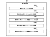
- FIG. 3 is a block diagram schematically showing the configuration of the second storage unit 124. As shown in FIG. 3, the second storage unit 124 includes a second service list storage unit 124A, a second scan channel list storage unit 124B, and a second channel scan completed list storage unit 124C.
- the second service list storage unit 124A stores a list of channel selection information necessary for receiving services broadcast in the second broadcasting system.
- the second service list storage unit 124A stores a second service list having channel selection information including network information, MF information, and service information extracted by the second control unit 125 for each channel.
- the second scan channel list storage unit 124B receives the electric signal generated from the radio wave, although the reception power of the radio wave received by the second tuner unit 120 is larger than a predetermined threshold during the channel scan.
- 2 Stores a second scan channel list, which is a list of identification information (here, channel numbers) for identifying a physical channel that has received a radio wave that could not be demodulated by the demodulator 121 (that could not be frame-locked).
- the reception power of radio waves received on a certain physical channel that has been subjected to CMMB channel scan, which is the second broadcasting system can stably view the DTMB service, which is the first broadcasting system.
- the second demodulator 121 cannot demodulate the electrical signal generated from this radio wave, which is greater than the first threshold value that is the lowest possible reception level, the channel number of such a physical channel is registered. Is.
- the first threshold (A) is a value obtained using the following equation (3).
- a [dBm] C / N [dB] + 10 log (kTW) + receiver noise figure [dB] ...
- 10 log (kTW) is a thermal noise figure
- C / N is C / N (required C / N) with respect to the bit error rate after decoding the inner code (LDPC code) that can be made pseudo-error free after decoding the outer code (BCH code).
- the receiver noise figure is a value obtained using the above equation (2).
- S i is the power level of the signal input to the second antenna 151
- N i is the second antenna.
- S i is the power level of the signal input to the second antenna 151
- N i is the second antenna.
- S o is the power level of the signal output from the second demodulator 121
- N o is the power level of noise output from the second demodulator 121
- the bottom of the log is 10. Since the value obtained by Expression (3) differs depending on the modulation scheme and coding rate at which the DTMB service is transmitted, the value calculated for each combination of the modulation scheme and coding rate at which the DTMB service is transmitted. It is desirable to use the lowest value as the first threshold value.
- the first threshold value may be a value selected from the minimum reception level of the reception power defined in accordance with the work mode (transmission mode) in the DTMB standard. For example, the lowest value among these minimum reception levels may be used as the first threshold value. Further, the lowest value among the minimum reception levels defined corresponding to the modulation scheme (for example, 4QAM, 16QAM, 32QAM, or 64QAM) used in actual broadcasting may be used as the first threshold value. Good.
- the working mode (transmission mode) is determined by, for example, a combination of the number of carriers, the forward error correction header bit rate, the frame header mode, the code cross option, and the band.
- the first threshold value is a value calculated from the equation (3) or a value selected from the minimum reception level of the reception power determined by the standard, in order to receive the service of the first broadcasting system. Indicates the minimum received power required.
- the second channel scan completed list storage unit 124 ⁇ / b> C is for identifying physical channels for which channel scanning has already been performed by the second tuner unit 120, the second demodulation unit 121, the second demultiplexer unit 122, and the second control unit 125.
- the second channel scan completed list which is a list of identification information (here, channel numbers) is stored.
- the second control unit 125 controls the process of scanning the second broadcast system channel and the process of receiving the second broadcast system broadcast.
- the second control unit 125 performs a first-phase CMMB channel scan and a second-phase CMMB channel scan.
- the first-phase CMMB channel scan the second control unit 125 overlaps the frequency band used in the first broadcasting system and the frequency band used in the second broadcasting system.
- the channel scanning is performed in a predetermined second order for the physical channels that are not yet subject to channel scanning by the first control unit 115.
- the second order is the reverse order of the first order in which the first control unit 115 controls the channel scan.
- the second control unit 125 performs channel scan on the physical channel that is determined by the first control unit 115 to have the necessary reception power but cannot be demodulated as the first broadcast method. I do.
- the second control unit 125 extracts channel selection information from the CIT given from the second demultiplexing unit 122, and the extracted channel selection information is stored in the second service list storage unit 124A of the second storage unit 124. Is registered in the second service list stored in the service list. For example, the second control unit 125 extracts Network_ID, which is a network identification value, and transmission frequencies of the master station and the relay station existing in the network from the NIT as network information. Further, the second control unit 125 extracts MF_ID (Multiple_Frame_ID), which is an identification value of the MF, from the MCT (Multiplex_Configuration_Table) as MF information.
- Network_ID which is a network identification value
- MF_ID Multiple_Frame_ID
- the second control unit 125 extracts SVC_ID (Service_ID), which is an identification value of each service, from the MCT as information of each service multiplexed in the MF.
- SVC_ID Service_ID
- These network information, MF information, and service information are channel selection information necessary for selecting a service, and are extracted from the second digital signal for each physical channel during channel scanning.
- the video switching unit 130 selects a video signal from the first decoding unit 113 and outputs it to the video synthesis unit 131 when a service broadcast in the DTMB format is viewed.
- the video switching unit 130 selects a video signal from the second decoding unit 123 and outputs the video signal to the video synthesis unit 131 when a service broadcast in the CMMB format is viewed.
- the video switching unit 130 switches the video signal to be selected in response to an instruction from the UIF processing unit 134.
- the video composition unit 131 converts the video of the screen indicated by the first service list list screen signal or the second service list list screen signal given from the UIF processing unit 134 into the video of the video signal given from the video switching unit 130.
- the combined video signal is output to the display unit 152.
- the video composition unit 131 receives the video signal of the screen indicated by the first service list list screen signal or the second service list list screen signal given from the UIF processing unit 134 as the video signal given from the video switching unit 130. Instead of this, it may be output to the display unit 152.
- the video composition unit 131 gives the video signal given from the video switching unit 130. Is output to the display unit 152.
- the audio switching unit 132 selects the audio signal from the first decoding unit 113 and outputs it to the audio output unit 153 when a service broadcast in the DTMB format is viewed. Also, the audio switching unit 132 selects the audio signal from the second decoding unit 123 and outputs the audio signal to the audio output unit 153 when a service broadcast in the CMMB format is viewed.
- the input unit 133 receives an instruction input from the user, and outputs an operation signal corresponding to the instruction input from the user.
- the input unit 133 can be realized by a remote controller, for example.
- the UIF processing unit 134 receives an operation signal from the input unit 133 and gives an instruction corresponding to the operation signal to each unit of the digital broadcast receiving apparatus 100.
- the UIF processing unit 134 acquires the first service list stored in the first service list storage unit 114A.
- a screen signal of the first service list list screen is generated from the acquired list.
- the UIF processing unit 134 provides the generated screen signal to the video composition unit 131 via the first storage unit 114.
- the UIF processing unit 134 acquires the second service list stored in the second service list storage unit 124A.
- a screen signal of the second service list list screen is generated from the acquired list.
- the UIF processing unit 134 gives the generated screen signal to the video composition unit 131 via the second storage unit 124.
- the display unit 152 displays a video based on the video signal given from the video synthesis unit 131.
- the audio output unit 153 outputs audio based on the audio signal given from the audio switching unit 132.
- the channel scan of the digital broadcast receiving apparatus 100 in the first embodiment is performed when the initial setting of the digital broadcast receiving apparatus 100 is performed, when the broadcast configuration is changed, or when a receiver is mounted on a mobile body. It is executed when moving to another broadcast area across the area, and a digital broadcast service list of each broadcast system of DTMB and CMMB is generated.
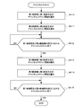
- FIG. 4 is a flowchart showing processing performed by the UIF processing unit 134 when channel scanning is selected by a user operation.
- the UIF processing unit 134 When the UIF processing unit 134 receives the operation signal indicating the channel scan request from the input unit 133, the UIF processing unit 134 notifies the first control unit 115 of the start of the channel scan of the first broadcast system (step S10).
- the UIF processing unit 134 notifies the second control unit 125 of the start of channel scanning for the second broadcast method (step S11).
- the first control unit 115 and the second control unit 125 are notified of the start of the channel scan, so that the DTMB channel scan under the control of the first control unit 115 and the CMMB under the control of the second control unit 125 are performed.
- Channel scanning is performed in parallel.
- the UIF processing unit 134 waits until receiving both a channel scan completion notification from the first control unit 115 and a channel scan completion notification from the second control unit 125 (step S12). Upon receiving these notifications (YES in step S12), the UIF processing unit 134 ends the process. When the process is completed, the UIF processing unit 134 generates a video signal of a notification screen indicating that the channel scan process is completed, and outputs the video signal to the display unit 152 via the video synthesis unit 131. Such a screen may be displayed on the display unit 152.
- step S10 after the first control unit 115 is notified of the start of channel scanning (step S10), the second control unit 125 is notified of the start of channel scanning (step S11), but this order is reversed. It may be.
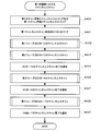
- FIG. 5 is a flowchart showing channel scan processing by the first control unit 115. For example, when the first control unit 115 receives a channel scan start notification from the UIF processing unit 134, the first control unit 115 starts the processing of the flowchart shown in FIG.
- the first control unit 115 clears (initializes) the first scan channel list stored in the first scan channel list storage unit 114B of the first storage unit 114 (step S20). For example, the first controller 115 erases all the channel numbers of physical channels stored in the first scan channel list.
- the first control unit 115 clears the first channel scan completed list stored in the first channel scan completed list storage unit 114C of the first storage unit 114 (step S21). For example, the first controller 115 erases all the channel numbers of the physical channels stored in the first channel scan completed list.
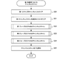
- the first control unit 115 performs a DTMB channel scan in the first phase (step S22). Details of this subroutine are shown in FIG. 7, but here, the first control unit 115 includes the physical band included in the range where the frequency band assigned to DTMB and the frequency band assigned to CMMB overlap. The channels are scanned in ascending order from the smallest channel number “13”. The first-phase DTMB channel scan ends when the physical channel selected as the next channel scan has already been scanned by the second controller 125.
- the first control unit 115 performs a second-phase DTMB channel scan (step S23). Details of this subroutine are shown in FIG. 9. Here, the first control unit 115 performs a channel scan on a physical channel whose channel number is registered in the second scan channel list acquired from the second control unit 125. Do.
- the first control unit 115 performs a third-phase DTMB channel scan (step S24). Details of this subroutine are shown in FIG. 11. Here, the first control unit 115 overlaps the frequency band assigned to the CMMB among the physical channels included in the frequency band assigned to the DTMB. A channel scan is performed for physical channels included in a non-existing range.
- the first control unit 115 notifies the UIF processing unit 134 of the completion of the channel scan (step S25).
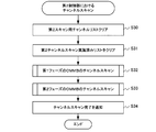
- FIG. 6 is a flowchart showing channel scan processing by the second control unit 125. For example, when the second control unit 125 receives a channel scan start notification from the UIF processing unit 134, the second control unit 125 starts the processing of the flowchart illustrated in FIG.
- the second control unit 125 clears the second scan channel list stored in the second scan channel list storage unit 124B of the second storage unit 124 (step S30).
- the second control unit 125 erases all the channel numbers of the physical channels stored in the second scan channel list.
- the second controller 125 clears the second channel scanned list stored in the second channel scanned list storage unit 124C of the second storage unit 124 (step S31).
- the second control unit 125 erases all the channel numbers of the physical channels stored in the second channel scan completed list.
- the second control unit 125 performs a channel scan of the first-phase CMMB (step S32).
- the second control unit 125 includes the physical band included in the overlapping range of the frequency band allocated to DTMB and the frequency band allocated to CMMB.
- channel scanning is performed in descending order from the maximum channel number “48” of the physical channel.
- the first-phase CMMB channel scan ends when the physical channel selected as the next channel scan has already been scanned by the first controller 115.
- the second control unit 125 executes a second-phase CMMB channel scan (step S33). Details of this subroutine are shown in FIG. 10, but here, the second control unit 125 performs a channel scan for the physical channels whose channel numbers are registered in the first scan channel list acquired from the first control unit 115. Do.
- the second control unit 125 notifies the UIF processing unit 134 of the completion of the channel scan (step S34).
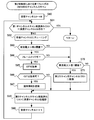
- FIG. 7 is a flowchart showing a first-phase DTMB channel scan subroutine performed by the first controller 115.
- the first control unit 115 sets the minimum channel number “13” as an initial value to the reception channel H as a variable indicating the physical channel for channel scanning (step S40).
- the first control unit 115 determines whether or not the reception channel H on which channel scanning is to be performed has already been channel scanned by the second control unit 125 (step S41). For example, the first control unit 115 obtains the second channel scan completed list stored in the second channel scan completed list storage unit 124C of the second storage unit 124 via the second control unit 125. Then, it is determined whether or not the reception channel H is registered in the second channel scan completed list. If the reception channel H is not registered in the second channel scan completed list (NO in step S41), the first control unit 115 proceeds to the process of step S42. Note that if the reception channel H is registered in the second channel scan completed list (YES in step S41), the first control unit 115 proceeds to the process of step S23 in FIG.
- step S42 the first control unit 115 instructs the first tuner unit 110 to receive the radio wave of the reception channel H.
- the first control unit 115 determines whether or not the reception level of the radio wave received by the tuned reception channel H is greater than the first threshold (step S43). For example, the first control unit 115 makes this determination by receiving a notification of a determination result from the first tuner unit 110 as to whether or not the radio wave reception level is higher than the first threshold value. If the reception level of the radio wave received by the reception channel H is higher than the first threshold (YES in step S43), the first control unit 115 proceeds to the process of step S44 and is received by the reception channel H. If the received radio wave level is equal to or lower than the first threshold (NO in step S43), the process proceeds to step S50. As described above, the first threshold indicates the lowest reception level at which DTMB service can be received and video and audio can be output.
- step S44 the first controller 115 determines whether or not the first demodulator 111 can demodulate the electrical signal generated from the radio wave of the reception channel H received by the first tuner unit 110. For example, the first control unit 115 performs this determination by receiving a notification from the first demodulating unit 111 on the result of performing demodulation processing on the electrical signal and determining whether or not the frame can be locked.
- the process proceeds to step S45.
- the process proceeds to step S50.
- the first controller 115 is likely to output TS from the first demodulator 111 to the first demultiplexer 112.
- the 1-demultiplex unit 112 is instructed to acquire SI (step S45).
- the first control unit 115 determines whether or not the first demultiplexing unit 112 has acquired the SI (step S46). If the first control unit 115 can acquire the SI (YES in step S46), the first control unit 115 proceeds to the process of step S47, and if the SI cannot be acquired (NO in step S46). In step S48, the process proceeds to step S48.
- step S47 the first control unit 115 registers the channel selection information of the service extracted from the SI in the first service list stored in the first service list storage unit 114A of the first storage unit 114.
- the first control unit 115 adds the reception channel H that has been subjected to the channel scan to the first channel scan completed list that is stored in the first channel scan completed list storage unit 114C of the first storage unit 114. Registration is performed (step S48).
- the first control unit 115 adds “1” to the reception channel H (step S49) and returns to the process of step S41 in order to perform the channel scan of the physical channels in ascending order.
- step S43 if the radio wave reception level is equal to or lower than the first threshold (NO in step S43), or if the frame is not locked in step S44 (NO in step S44).
- the first control unit 115 proceeds to the process of step S50.
- step S50 the first control unit 115 determines whether or not the reception level of the radio wave received by the reception channel H is higher than the second threshold value. For example, the first control unit 115 makes this determination by receiving a notification of a determination result from the first tuner unit 110 as to whether or not the radio wave reception level is higher than the second threshold value.
- step S50 When the reception level of the radio wave received on the reception channel H is higher than the second threshold (YES in step S50), the first control unit 115 proceeds to the process of step S51 and is received on the reception channel H. If the received radio wave level is equal to or lower than the second threshold (NO in step S50), the process proceeds to step S48.
- step S51 the first control unit 115 registers the reception channel H in the first scan channel list stored in the first scan channel list storage unit 114B of the first storage unit 114.
- the DTMB channel scan in the first phase by the first controller 115 is executed in ascending order from the channel number “13” of the physical channel.
- the first control unit 115 determines that the reception channel H to be channel scanned in step S41 has already been scanned by the second control unit 125, the first control unit 115 performs the DTMB channel scan in the first phase. Exit.
- the reception level evaluation based on the first threshold value and the second threshold value is performed by the first tuner unit 110.
- the reception level may be acquired, and the reception level may be compared with the first threshold value or the second threshold value for evaluation. Further, the process of acquiring SI and registering the channel selection information in the first service list performed in steps S45 to S47 in FIG. 7 may be executed at the timing shown in FIG. After all the channel scans are completed, all the services may be executed together.
- FIG. 8 is a flowchart showing a first-phase CMMB channel scan subroutine performed by the second controller 125.
- the second control unit 125 performs the first-phase CMMB channel scan in parallel with the first-phase DTMB channel scan performed by the first control unit 115.
- the second control unit 125 sets the maximum channel number “48” of the physical channel as an initial value to the reception channel I as a variable indicating the physical channel for channel scanning (step S60).
- the second control unit 125 determines whether or not the reception channel I about to perform channel scanning has already been channel scanned by the first control unit 115 (step S61). For example, the second controller 125 obtains the first channel scanned list stored in the first channel scanned list storage unit 114 ⁇ / b> C of the first storage unit 114 via the first controller 115. Then, it is determined whether or not the reception channel I is registered in the first channel scan completed list. Then, if the reception channel I is not registered in the first channel scan completed list (NO in step S61), the second control unit 125 proceeds to the process of step S62. When the reception channel I is registered in the first channel scan completed list (YES in step S61), the second control unit 125 proceeds to the process of step S33 in FIG.
- step S62 the second control unit 125 instructs the second tuner unit 120 to receive the radio wave of the reception channel I.
- the second control unit 125 determines whether or not the reception level of the radio wave received through the tuned reception channel I is greater than the second threshold (step S63). For example, the second control unit 125 performs this determination by receiving a notification of a determination result as to whether or not the reception level of the radio wave is higher than the second threshold value from the second tuner unit 120. Then, when the reception level of the radio wave received on the reception channel I is higher than the second threshold (YES in step S63), the second control unit 125 proceeds to the process of step S64 and is received on the reception channel I. If the received radio wave level is equal to or lower than the second threshold (NO in step S63), the process proceeds to step S70. As described above, the second threshold indicates the lowest reception level at which CMMB service can be received and video and audio can be output.
- step S64 the second controller 125 determines whether or not the second demodulator 121 can demodulate the electric signal generated from the radio wave of the reception channel I received by the second tuner unit 120. For example, the second controller 125 performs this determination by receiving a notification from the second demodulator 121 that performs demodulation processing on the electrical signal and receiving a result indicating whether or not the frame can be locked. If the second control unit 125 can demodulate (YES in step S64), the process proceeds to step S65. If the second control unit 125 cannot demodulate (NO in step S64), the second control unit 125 proceeds to the process in step S70.
- the second controller 125 is likely to output the MF stream from the second demodulator 121 to the second demultiplexer 122.
- the second demultiplexing unit 122 is instructed to acquire CIT (step S65).
- step S66 determines whether or not the CIT has been acquired by the second demultiplexing unit 122 (step S66). If the CIT can be acquired (YES in step S66), the second control unit 125 proceeds to the process of step S67, and if the CIT cannot be acquired (NO in step S66). In step S68, the process proceeds to step S68.
- step S67 the second control unit 125 registers the channel selection information of the service extracted from the CIT in the second service list stored in the second service list storage unit 124A of the second storage unit 124.
- the second control unit 125 adds the received channel I for which the channel scan has been performed to the second channel scan completed list stored in the second channel scan completed list storage unit 124C of the second storage unit 124. sign up.
- the second control unit 125 subtracts “1” from the reception channel I (step S69) and returns to the process of step S61 in order to perform the channel scan of the physical channels in descending order.
- step S63 the reception level of the radio wave is equal to or lower than the second threshold (NO in step S63), or the frame is not locked in step S64 (NO in step S64).
- the second control unit 125 proceeds to the process of step S70.
- step S70 the second control unit 125 determines whether or not the reception level of the radio wave received on the reception channel I is greater than the first threshold value. For example, the second control unit 125 performs this determination by receiving a notification from the second tuner unit 120 regarding whether or not the reception level of the radio wave is higher than the first threshold value.
- step S70 When the reception level of the radio wave received on the reception channel I is higher than the first threshold (YES in step S70), the second control unit 125 proceeds to the process of step S71 and is received on the reception channel I. If the received radio wave level is equal to or lower than the first threshold (NO in step S70), the process proceeds to step S68.
- step S71 the second control unit 125 registers the reception channel I in the second scan channel list stored in the second scan channel list storage unit 124B of the second storage unit 124.
- the CMMB channel scan in the first phase by the second controller 125 is executed in descending order from the maximum channel number “48” of the physical channel. Then, if the second control unit 125 determines in step S61 that the reception channel I for which channel scanning is to be performed has already been channel-scanned by the first control unit 115, the CMMB channel scan in the first phase. Exit.
- the reception level evaluation based on the first threshold value and the second threshold value is performed by the second tuner unit 120.
- the second control unit 125 receives the reception channel I from the second tuner unit 120.
- the reception level of the radio wave received in step 1 may be acquired and compared with the first threshold value or the second threshold value for evaluation.
- the process of acquiring CIT and registering channel selection information in the second service list performed in steps S65 to S67 of FIG. 8 may be executed at the timing shown in FIG. After all the channel scans are completed, all the services may be collectively executed.
- FIG. 9 is a flowchart showing a second-phase DTMB channel scan subroutine performed by the first controller 115.
- the first control unit 115 acquires the second scan channel list stored in the second scan channel list storage unit 124B of the second storage unit 124 via the second control unit 125, and performs the second scan use. It is determined whether or not all physical channels whose channel numbers are registered in the channel list have been selected (step S80). If the first control unit 115 has not selected all physical channels whose channel numbers are registered in the second scan channel list (NO in step S80), in other words, the first control unit 115 has not been selected yet. If channel numbers of physical channels that do not exist exist in the second scan channel list, the process proceeds to step S81, and all physical channels registered in the second scan channel list are selected. (YES in step S80) In other words, if the channel number of the physical channel that has not been selected yet does not exist in the second scan channel list, the process proceeds to step S24 in FIG.
- step S81 the first control unit 115 obtains channel numbers from the second scan channel list in the registered order (in other words, in descending order of channel numbers), and is a reception channel that is a variable indicating a physical channel. Set to J. Therefore, in step S81, the largest channel number among the physical channels registered in the second scan channel list and not yet set in the reception channel J in step S81 is set in the reception channel J.
- the order of registration is used, but the order is not limited to this, and the reception channel J may be set in another order.
- the first control unit 115 instructs the first tuner unit 110 to tune to a frequency corresponding to the physical channel indicated by the reception channel J (step S82).
- the first control unit 115 determines whether or not the reception level of the radio wave received by the tuned reception channel J is higher than the first threshold (step S83). For example, the first control unit 115 makes this determination by receiving a notification of a determination result from the first tuner unit 110 as to whether or not the radio wave reception level is higher than the first threshold value. If the reception level of the radio wave received by the reception channel J is higher than the first threshold (YES in step S83), the first control unit 115 proceeds to the process of step S84 and is received by the reception channel J. If the received radio wave level is equal to or lower than the first threshold (NO in step S83), the process returns to step S80.
- step S84 the first controller 115 determines whether or not the first demodulator 111 can demodulate the electric signal generated from the radio wave of the reception channel J received by the first tuner unit 110. For example, the first control unit 115 performs this determination by receiving a notification from the first demodulating unit 111 on the result of performing demodulation processing on the electrical signal and determining whether or not the frame can be locked. If the first control unit 115 can demodulate (YES in step S84), the process proceeds to step S85. If the first control unit 115 cannot demodulate (NO in step S84), the process returns to step S80.
- the first controller 115 is likely to output TS from the first demodulator 111 to the first demultiplexer 112.
- the 1-demultiplex unit 112 is instructed to acquire SI (step S85).
- the first control unit 115 determines whether or not the first demultiplexing unit 112 has acquired the SI (step S86). If the first control unit 115 can acquire the SI (YES in step S86), the first control unit 115 proceeds to the process of step S87, and if the SI cannot be acquired (NO in step S86). Returns to the process of step S80.
- step S87 the first control unit 115 registers the channel selection information of the service extracted from the SI in the first service list stored in the first service list storage unit 114A of the first storage unit 114.
- the first control unit 115 performs a channel scan only for the physical channels whose channel numbers are registered in the second scan channel list.
- the first control unit 115 receives only the physical channel that has received the radio wave that has the necessary reception power but could not be demodulated as the CMMB.
- scanning is performed in the DTMB channel scan in the second phase, so that efficient channel scan can be performed.
- step S83 in FIG. 9 the reception level evaluation based on the first threshold value is performed by the first tuner unit 110.
- the reception level may be acquired, and the reception level may be compared with the first threshold value for evaluation. Further, the process of acquiring SI and registering the channel selection information in the first service list performed in steps S85 to S87 in FIG. 9 may be executed at the timing shown in FIG. After all the channel scans are completed, all the services may be executed together.
- FIG. 10 is a flowchart showing a second-phase CMMB channel scan subroutine performed by the second controller 125.
- the second control unit 125 performs the second-phase CMMB channel scan in parallel with the second-phase DTMB channel scan performed by the first control unit 115.
- the second control unit 125 acquires the first scan channel list stored in the first scan channel list storage unit 114B of the first storage unit 114 via the first control unit 115, and performs the first scan use. It is determined whether all the physical channels registered in the channel list have been selected (step S90). If the second control unit 125 has not selected all the physical channels registered in the first scan channel list (NO in step S90), in other words, the physical channel that has not been selected yet. However, if it exists in the first scan channel list, the process proceeds to step S91, and if all the physical channels registered in the first scan channel list are selected (YES in step S90). In other words, if there is no physical channel that has not been selected yet in the first scan channel list, the process proceeds to step S34 in FIG.
- step S91 the second control unit 125 acquires the channel numbers of the physical channels from the first scan channel list in the registered order (in other words, in ascending order of the channel numbers), and is a variable indicating the physical channel. Set to a certain receiving channel L. Accordingly, in step S91, the physical channel that is registered in the first scan channel list and that has not been set in the reception channel L in step S91 and that has the smallest channel number is set in the reception channel L. Will be.
- the order of registration is used, but the order is not limited to this, and the reception channel L may be set in another order.
- the second control unit 125 instructs the second tuner unit 120 to tune to a frequency corresponding to the physical channel indicated by the reception channel L (step S92).
- the second control unit 125 determines whether or not the reception level of the radio wave received by the tuned reception channel L is higher than the second threshold (step S93). For example, the second control unit 125 performs this determination by receiving a notification of a determination result as to whether or not the reception level of the radio wave is higher than the second threshold value from the second tuner unit 120. If the reception level of the radio wave received by the reception channel L is greater than the second threshold (YES in step S93), the second control unit 125 proceeds to the process of step S94 and is received by the reception channel L. If the received radio wave level is equal to or lower than the second threshold (NO in step S93), the process returns to step S90.
- step S94 the second controller 125 determines whether or not the second demodulator 121 can demodulate the electric signal generated from the radio wave of the reception channel L received by the second tuner unit 120. For example, the second controller 125 performs this determination by receiving a notification from the second demodulator 121 that performs demodulation processing on the electrical signal and receiving a result indicating whether or not the frame can be locked. If the second control unit 125 can demodulate (YES in step S94), the process proceeds to step S95. If the second control unit 125 cannot demodulate (NO in step S94), the process returns to step S90.
- the second controller 125 is likely to output the MF stream from the second demodulator 121 to the second demultiplexer 122.
- the second demultiplexer 122 is instructed to acquire CIT (step S95).
- the second control unit 125 determines whether or not the CIT has been acquired by the second demultiplexing unit 122 (step S96). If the CIT can be acquired (YES in step S96), the second control unit 125 proceeds to the process of step S97, and if the CIT cannot be acquired (NO in step S96). Returns to the process of step S90.
- step S97 the second control unit 125 registers the channel selection information of the service extracted from the CIT in the second service list stored in the second service list storage unit 124A of the second storage unit 124.
- the second control unit 125 performs the channel scan only for the physical channels whose channel numbers are registered in the first scan channel list. In other words, as a result of the first-phase DTMB channel scan, the second control unit 125 obtains only the physical channel that has received the radio wave that has the necessary power but could not be demodulated as the DTMB. Instead of all physical channels handled by the first controller 115 in the channel scan, scanning is performed in the CMMB channel scan in the second phase, so that efficient channel scan can be performed.
- the evaluation of the reception level based on the second threshold value in step S93 in FIG. 10 is performed by the second tuner unit 120.
- the second control unit 125 receives the radio wave received from the second tuner unit 120 via the reception channel L.
- the reception level may be acquired and compared with the second threshold value for evaluation.
- the process of acquiring the CIT and registering the channel selection information in the second service list performed in steps S95 to S97 of FIG. 10 may be executed at the timing shown in FIG. After all the channel scans are completed, all the services may be collectively executed.
- FIG. 11 is a flowchart showing a third-phase DTMB channel scan subroutine performed by the first control unit 115. Since the band of DTMB, which is the first broadcasting system, is from 13 channels to 56 channels, the first control unit 115 is from 49 channels to 56 channels after 48 channels completed in the second phase channel scan. This channel scan is executed as a third-phase DTMB channel scan.
- the first control unit 115 sets the channel number “49” as an initial value to the reception channel M as a variable indicating a physical channel for channel scanning in order to perform channel scanning in ascending order from the 49th channel (step S100).
- the first control unit 115 determines whether channel scanning has already been performed for 56 channels (step S101). For example, the first control unit 115 makes this determination based on whether or not the reception channel M on which channel scanning is to be performed exceeds “56”, which is the maximum physical channel number for channel scanning. If the channel scan is not yet performed for 56 channels (NO in step S101), the first control unit 115 proceeds to the process of step S102, and if the channel scan is already performed for 56 channels (step). If YES in S101, the process proceeds to step S25 in FIG.
- step S102 the first control unit 115 instructs the first tuner unit 110 to tune to a frequency corresponding to the physical channel indicated by the reception channel M.
- the first control unit 115 determines whether or not the reception level of the radio wave received by the tuned reception channel M is higher than the first threshold (step S103). For example, the first control unit 115 makes this determination by receiving a notification of a determination result from the first tuner unit 110 as to whether or not the radio wave reception level is higher than the first threshold value.
- the first control unit 115 proceeds to the process of step S104 and is received by the reception channel M. If the received radio wave level is equal to or lower than the first threshold (NO in step S103), the process proceeds to step S108.
- step S104 the first controller 115 determines whether or not the first demodulator 111 can demodulate the electric signal generated from the radio wave of the reception channel M received by the first tuner unit 110. For example, the first control unit 115 performs this determination by receiving a notification from the first demodulating unit 111 on the result of performing demodulation processing on the electrical signal and determining whether or not the frame can be locked. If the first control unit 115 can demodulate (YES in step S104), the process proceeds to step S105. If the first control unit 115 cannot demodulate (NO in step S104), the first control unit 115 proceeds to the process in step S108.
- the first controller 115 is likely to output TS from the first demodulator 111 to the first demultiplexer 112.
- the 1-demultiplex unit 112 is instructed to acquire SI (step S105).
- the first control unit 115 determines whether or not the first demultiplexing unit 112 has acquired the SI (step S106). If the first control unit 115 can acquire the SI (YES in step S106), the first control unit 115 proceeds to the process of step S107, and if the SI cannot be acquired (NO in step S106). In step S108, the process proceeds to step S108.
- step S107 the first control unit 115 registers the channel selection information of the service extracted from the SI in the first service list stored in the first service list storage unit 114A of the first storage unit 114.
- the first control unit 115 adds 1 to the reception channel M (step S108) and returns to the process of step S101 in order to perform channel scanning of the physical channels in ascending order.
- the DTMB channel scan in the third phase by the first controller 115 is performed in ascending order from the channel number “49” of the physical channel. If the first control unit 115 determines that the reception channel M for which channel scanning is to be performed has already exceeded the maximum channel number “56” in step S101, the first control unit 115 performs DTMB in the third phase. End channel scan.
- step S103 of FIG. 11 the reception level evaluation based on the first threshold is performed by the first tuner unit 110.
- the first control unit 115 receives the radio wave received from the first tuner unit 110 via the reception channel M.
- the reception level may be acquired and compared with the first threshold value for evaluation.
- the process of acquiring SI and registering the channel selection information in the first service list performed in steps S105 to S107 in FIG. 11 may be executed at the timing shown in FIG. After all the channel scans are completed, all the services may be collectively executed.
- FIG. 12 is a schematic diagram for explaining channel scanning performed by the digital broadcast receiving apparatus 100.
- FIG. 12 shows a state in which the time advances from left to right and the DTMB channel scan and the CMMB channel scan are started simultaneously.
- the first phase channel scan includes a first phase DTMB channel scan and a first phase CMMB channel scan.
- the second phase channel scan includes a second phase DTMB channel scan and a second phase DTMB channel scan. Phase CMMB channel scans are included, and third phase channel scans include third phase DTMB channel scans.
- the DTMB channel scan is executed in the order of the first phase DTMB channel scan, the second phase DTMB channel scan, and the third phase DTMB channel scan.
- the channel scan is executed in the order of the CMMB channel scan in the first phase and the CMMB channel scan in the second phase.
- first-phase DTMB channel scan channel scans are performed in ascending order from 13 channels, and in the first-phase CMMB channel scan, channel scans are performed in descending order from 48 channels.
- first-phase DTMB channel scan is performed up to 30 channels and the first-phase CMMB channel scan is performed up to 31 channels, each channel scan end condition (step S41 in FIG. Step S61) in FIG. 8 is established, and each channel scan in the first phase is completed.
- the first control unit 115 received a radio wave in 14 channels because the radio wave reception level was higher than the second threshold but could not be demodulated without frame locking. It is determined that it is not a DTMB broadcast wave, and 14 channels are registered in the first scan channel list (step S51 in FIG. 7).
- the second control unit 125 received the received radio wave because the reception level of the radio wave was higher than the first threshold value in 46 channels, but could not be demodulated without frame locking. Is not a CMMB broadcast wave, and 46 channels are registered in the second scan channel list (step S71 in FIG. 8).
- the radio wave reception level is higher than a predetermined threshold value in the other first-phase channel scan.
- the channel scan is performed only for the channels that could not demodulate the electrical signal generated from the.
- the reception level of the radio wave is higher than the first threshold in the first-phase CMMB channel scan, but only the 46 channels that could not demodulate the electric signal due to this radio wave are detected.
- the first demodulator 111 can perform demodulation, and the first controller 115 extracts channel selection information and registers it in the first service list. To do.
- the radio wave reception level is higher than the second threshold in the first-phase DTMB channel scan, but only the 14 channels that could not demodulate the electric signal due to this radio wave are detected.
- the second demodulator 121 can perform demodulation, and the second controller 125 extracts channel selection information and registers it in the second service list.
- the characteristic of each channel scan in the second phase is that the radio wave reception level detected by the channel scan in the first phase of the other broadcasting system is larger than a predetermined threshold. The channel scan is performed only for channels that could not be demodulated.
- CMMB channel scan This completes the CMMB channel scan, and the DTMB channel scan further performs a third-phase DTMB channel scan.
- the channels from the 13th channel to the 48th channel are selected at least once in the channel scan of DTMB or CMMB.
- channel scans from 49 channels to 56 channels that have not been selected yet are performed.
- channel scanning up to 56 channels is completed, the entire channel scanning is completed.
- digital broadcast receiving apparatus 100 includes a tuner unit, a demodulation unit, and a demultiplexing unit that correspond to a plurality of different broadcasting systems, and each channel scan is performed. Broadcast channel scans are executed in parallel, so the time required for channel scans can be reduced.
- the first control unit 115 and the second control unit 125 perform the frequency band used by the DTMB and the frequency band used by the CMMB in the first-phase channel scan.
- Channel scanning is performed by sharing the channels included in the overlapping range so that they do not overlap.
- the first control unit 115 and the second control unit 125 were not able to demodulate the electric signal due to the radio wave in the first phase channel scan process, although the radio wave reception level was higher than a predetermined threshold. Record the channel number of the physical channel.
- the first control unit 115 and the second control unit 125 perform the channel scan only on the channel of the channel number recorded by the other in the channel scan of the second phase, the first control unit 115 and the second control unit 125 have an effect of shortening the channel scan time by about 1 ⁇ 2 at the maximum as compared with the case where the channel is simply scanned for all the channels.
- digital broadcast receiving apparatus 100 includes a tuner unit for each broadcasting system, and these tuner units can view the services of the broadcasting system that they support.
- One threshold which is the lowest reception level
- another threshold which is a reception level at which the other broadcast system service can be viewed, are set.
- Each tuner unit not only determines whether the reception level necessary for viewing the service of the broadcasting system that it supports is satisfied, but also uses the other threshold value for the service of the other broadcasting system. It is determined whether or not the reception level necessary for viewing is satisfied.
- reception level threshold for receiving DTMB which is broadcast for fixed devices
- threshold for reception level for receiving CMMB which is broadcast for mobile devices
- the digital broadcast receiving apparatus 100 compared with the conventional technique that includes two systems of a tuner unit and a demodulation unit that receive the same broadcasting system, divides the channel scan band into two, and performs channel scanning in parallel, the digital broadcast receiving apparatus 100 according to Embodiment 1
- the first threshold value and the second threshold value are set to the lowest reception levels at which each broadcast system service can be received, it is highly likely that the service cannot be viewed.
- the physical channel of the level can be excluded from the channel scan candidates of the second phase, and the time required for each channel scan of the second phase can be shortened.
- the minimum reception level at which services can be stably received depends on each modulation scheme. Since the modulation method used in a certain physical channel is not known unless broadcast waves are received, if the reception level used as the threshold is the smallest minimum reception level value among the assumed modulation methods, it was generated by channel scanning.
- the service list is a reliable service that can be received without missing any services.
- FIG. FIG. 13 is a block diagram schematically showing a configuration of digital broadcast receiving apparatus 200 according to Embodiment 2.
- the digital broadcast receiving apparatus 200 includes a first tuner unit 110, a first demodulation unit 111, a first demultiplexing unit 112, a first decoding unit 113, and a first storage unit 114.
- the digital broadcast receiving apparatus 200 according to the second embodiment is different from the digital broadcast receiving apparatus 100 according to the first embodiment in the processing by the UIF processing unit 234.
- the UIF processing unit 234 receives an operation signal from the input unit 133 and gives an instruction corresponding to the operation signal to each unit of the digital broadcast receiving apparatus 200. Similarly to the first embodiment, the UIF processing unit 234 receives the operation signal for displaying the first service list list screen or the second service list list screen from the input unit 133. The first service list stored in the storage unit 114A or the second service list stored in the second service list storage unit 124A is acquired, and the first service list list screen or the second service list list is acquired from the acquired list. Generate a screen signal for the screen. Then, the UIF processing unit 234 gives the generated screen signal to the video composition unit 131 via the first storage unit 114 or the second storage unit 124.
- the UIF processing unit 234 is stored in the first service list stored in the first service list storage unit 114A when the channel scan of the first broadcasting system is completed.
- the second service list is acquired, and a screen signal of the first service list list screen is generated from the acquired list. Then, the UIF processing unit 234 gives the generated screen signal to the video composition unit 131 via the first storage unit 114.
- the UIF processing unit 234 acquires the second service list stored in the second service list storage unit 124A when the channel scan of the second broadcasting method is completed. Then, a screen signal of the second service list list screen is generated from the acquired list. Then, the UIF processing unit 234 gives the generated screen signal to the video composition unit 131 via the second storage unit 124.
- FIG. 14 is a flowchart showing processing performed by the UIF processing unit 234 when channel scanning is selected by a user operation.
- the UIF processing unit 234 When the UIF processing unit 234 receives an operation signal indicating a channel scan request from the input unit 133, the UIF processing unit 234 notifies the first control unit 115 of the start of channel scanning (step S110).
- the DTMB channel scan executed by the first controller 115 is the same as that described in the first embodiment.
- the UIF processing unit 234 notifies the second control unit 125 of the start of channel scanning (step S111).
- the CMMB channel scan executed by the second controller 125 is the same as that described in the first embodiment.
- the UIF processing unit 234 determines whether or not a notification indicating that the CMMB channel scan is completed is received from the second control unit 125 (step S112).
- the UIF processing unit 234 receives a notification indicating that the CMMB channel scan has been completed (YES in step S112)
- the UIF processing unit 234 proceeds to the process of step S113 and notifies that the CMMB channel scan has been completed. If not received (NO in step S112), the process proceeds to step S116.
- step S113 the UIF processing unit 234 acquires the second service list stored in the second service list storage unit 124A, generates a screen signal of the second service list list screen, and synthesizes the screen signal with the video composition.
- the first control unit 115 performs channel scanning for the physical channels for which channel scanning has not ended.
- the first control unit 115 executes channel scans from 49 channels to 56 channels as the third-phase DTMB channel scan.
- the UIF processing unit 234 causes the second control unit 125, the video switching unit 130, and the audio switching unit 132 to respond to a service displayed on the second service list list screen when a user performs a channel selection operation. By issuing an instruction, the CMMB service is selected, decoded, and displayed.
- the UIF processing unit 234 waits for a notification from the first control unit 115 indicating that the DTMB channel scan has been completed (step S114). If the UIF processing unit 234 receives a notification indicating that the DTMB channel scan has been completed (YES in step S114), the UIF processing unit 234 proceeds to the process in step S115.
- step S115 the UIF processing unit 234 generates a screen signal indicating a message indicating completion of generation of the first service list, gives this screen signal to the video composition unit 131, and causes the display unit 152 to display it.
- a message is displayed smaller than the CMMB service screen by OSD (On-Screen Display) when the CMMB service is already displayed, and the second service list is displayed. Is displayed together with a display enabling selection of the first service list display.
- OSD On-Screen Display
- step S112 if the notification indicating that the CMMB channel scan is completed is not received in step S112 (NO in step S112), the UIF processing unit 234 proceeds to the process of step S116.
- step S116 the UIF processing unit 234 determines whether or not a notification indicating that the DTMB channel scan has been completed is received from the first control unit 115.
- the UIF processing unit 234 receives a notification indicating that the DTMB channel scan has been completed (YES in step S116)
- the UIF processing unit 234 proceeds to the process of step S117, and indicates that the DTMB channel scan has been completed. If not received (NO in step S116), the process returns to step S112.
- the target band for the CMMB channel scan is narrower than the target band for the DTMB channel scan, the processing of steps S112 to S115 is usually performed. However, the DTMB completes the channel scan earlier than the CMMB. If so, the processing from step S112 to S119 is performed.
- step S117 the UIF processing unit 234 acquires the first service list stored in the first service list storage unit 114A, generates a screen signal of the first service list list screen, and synthesizes the screen signal with the video synthesis. To display on the display unit 152. Note that the UIF processing unit 234 causes the first control unit 115, the video switching unit 130, and the audio switching unit 132 when the user selects a channel for the service displayed on the first service list list screen. By issuing an instruction, the DTMB service is selected, decoded, and displayed.
- the UIF processing unit 234 waits until receiving a notification from the second control unit 125 indicating that the CMMB channel scan has been completed (step S118).
- the UIF processing unit 234 receives a notification indicating that the CMMB channel scan is completed (YES in step S118)
- the UIF processing unit 234 proceeds to the process of step S119.
- step S119 the UIF processing unit 234 generates a screen signal indicating a message indicating the completion of the generation of the second service list, gives this screen signal to the video composition unit 131, and causes the display unit 152 to display the screen signal.
- a message is displayed smaller than the DTMB service screen by the OSD when the DTMB service is already displayed, and when the first service list is displayed. , Displayed together with a display enabling selection of the second service list display.
- the service list that has been completed first among the DTMB and CMMB channel scans is displayed on the display unit 152 before the other channel scan is completed. Since the service can be selected and displayed, the waiting time of the user can be shortened.
- FIG. 15 is a block diagram schematically showing a configuration of digital broadcast receiving apparatus 300 according to the third embodiment.
- the digital broadcast receiving apparatus 300 includes a first tuner unit 110, a first demodulation unit 111, a first demultiplexing unit 112, a first decoding unit 113, and a first storage unit 314.
- a video switching unit 130 a video synthesis unit 131, an audio switching unit 132, an input unit 133, a UIF processing unit 334, a third tuner unit 360, a third demodulation unit 361, and a third demultiplexer A plexer 362, a third controller 363, a fourth tuner unit 370, a fourth demodulator 371, a fourth demultiplexer 372, and a fourth controller 373 are provided.
- the digital broadcast receiving apparatus 300 includes points of control in the first control unit 315 and the second control unit 325, points of information stored in the first storage unit 314 and the second storage unit 324, In addition, the third tuner unit 360, the third demodulation unit 361, the third demultiplexing unit 362, the third control unit 363, the fourth tuner unit 370, the fourth demodulation unit 371, the fourth demultiplexing unit 372, and the fourth
- the digital broadcast receiving apparatus 100 according to the first embodiment is different from the digital broadcast receiving apparatus 100 in that the control unit 373 is further provided.
- a third antenna 354 is connected to the third tuner unit 360, and the third antenna 354, the third tuner unit 360, the third demodulation unit 361, the third demultiplexing unit 362, and the third control unit 363 are This is a DTMB system that performs channel scanning of a DTMB broadcast as the first broadcast system.
- a fourth antenna 355 is connected to the fourth tuner unit 370, and the fourth antenna 355, the fourth tuner unit 370, the fourth demodulation unit 371, the fourth demultiplexing unit 372, and the fourth control unit 373 include The CMMB system performs channel scanning of CMMB broadcasting as the second broadcasting system.
- the first storage unit 314 stores information necessary for scanning the channels of the first broadcasting system and the second broadcasting system, and information necessary for receiving a service broadcast in the first broadcasting system.
- FIG. 16 is a block diagram schematically showing the configuration of the first storage unit 314.
- the first storage unit 314 includes a first service list storage unit 114A, a first scan channel list storage unit 114B, a first channel scan completed list storage unit 114C, and a third scan.
- Channel list storage unit 314D and a third channel scan completed list storage unit 314E is different from the first storage unit 114 according to the first embodiment in that it includes a third scan channel list storage unit 314D and a third channel scan completed list storage unit 314E. Is different.
- the third scan channel list storage unit 314D receives the electric signal generated from the radio wave, although the radio wave received by the third tuner unit 360 has a reception power larger than a predetermined threshold during the channel scan.
- a third scan channel list that is a list of identification information (here, channel numbers) for identifying physical channels that could not be demodulated by the 3 demodulator 361 (frame lock could not be performed) is stored.
- the radio wave received in the physical channel that has been subjected to the DTMB channel scan as the first broadcast method is larger than the second threshold value, and the third demodulator 361 The channel number of such a physical channel is registered when the electric signal generated from the signal cannot be demodulated.
- the third channel scan completed list storage unit 314E identifies physical channels that have already been scanned by the third tuner unit 360, the third demodulation unit 361, the third demultiplexer unit 362, and the third control unit 363.
- the third channel scan completed list which is a list of identification information (here, channel numbers) is stored.
- the first control unit 315 controls the process of scanning the channel of the first broadcast system and the process of receiving the broadcast of the first broadcast system.
- the first control unit 315 performs DTMB channel scanning in the first phase, the second phase, and the third phase.
- the first control unit 315 overlaps the frequency band used in the first broadcasting system and the frequency band used in the second broadcasting system.
- the physical channels included in the range physical channels that are not yet subject to channel scanning by the second control unit 325 and the fourth control unit 373 are shared with the third control unit 363 and determined in advance. The channel scan is performed in the first order.
- the first control unit 315 is determined by the second control unit 325 and the fourth control unit 373 that there is necessary reception power but cannot be demodulated as the second broadcast system.
- the physical channel is shared with the third control unit 363 to perform channel scanning.
- the first control unit 315 uses the frequency used in the first broadcast system broadcast among the physical channels included in the frequency band used in the first broadcast system broadcast.
- a physical channel that is not included in the range where the band and the frequency band used in the broadcasting of the second broadcasting system overlap is shared with the third control unit 363 to perform channel scanning.
- the first control unit 315 extracts channel selection information from the first data (PSI and SI) given from the first demultiplexing unit 112, and the extracted channel selection information is stored in the first storage unit 314. A process of registering in the first service list stored in the one service list storage unit 114A is performed.
- the second storage unit 324 stores information necessary for scanning and receiving broadcasts of the second broadcast system and the first broadcast system.
- FIG. 17 is a block diagram schematically showing the configuration of the second storage unit 324.
- the second storage unit 324 includes a second service list storage unit 124A, a second scan channel list storage unit 124B, a second channel scan completed list storage unit 124C, and a fourth scan.
- Channel list storage unit 324D and a fourth channel scan completed list storage unit 324E is different from the second storage unit 124 according to the first embodiment in that it includes a fourth scan channel list storage unit 324D and a fourth channel scan completed list storage unit 324E. Is different.
- the fourth scan channel list storage unit 324D receives the electric signal generated from the radio wave generated by the radio wave received by the fourth tuner unit 370 when the channel scan is greater than a predetermined threshold.
- a fourth scan channel list that is a list of identification information (here, channel numbers) for identifying physical channels that could not be demodulated by the 4 demodulator 371 (frame lock could not be performed) is stored.
- identification information here, channel numbers
- the fourth scan channel list radio waves received on a physical channel that has been subjected to CMMB channel scan, which is the second broadcast method, are larger than the first threshold, and electric signals generated from the radio waves are displayed.
- CMMB channel scan which is the second broadcast method
- the fourth channel scan completed list storage unit 324E identifies physical channels for which channel scan has already been performed by the fourth tuner unit 370, the fourth demodulation unit 371, the fourth demultiplexer unit 372, and the fourth control unit 373.
- the fourth channel scanned list which is a list of identification information (here, channel numbers), is stored.
- the second control unit 325 controls the process of scanning the second broadcast system channel and the process of receiving the second broadcast system broadcast.
- the second control unit 325 performs channel scan of CMMB in the first phase and the second phase.
- the second control unit 325 overlaps the frequency band used in the first broadcasting system and the frequency band used in the second broadcasting system.
- the physical channels included in the range physical channels that are not yet subject to channel scanning by the first control unit 315 and the third control unit 363 are shared with the fourth control unit 373 and determined in advance.
- the channel scan is performed in the second order.
- the second order is the reverse order of the first order in which the first control unit 315 controls the channel scan.
- the second control unit 325 determines that the first control unit 315 and the third control unit 363 have the received power necessary but cannot demodulate as the first broadcast system.
- the channel scan is performed on the physical channel thus shared with the fourth controller 373.
- the second control unit 325 extracts channel selection information from the second data (CIT) given from the second demultiplexing unit 122, and the extracted channel selection information is stored in the second service of the second storage unit 324. A process of registering in the second service list stored in the list storage unit 124A is performed.
- the UIF processing unit 334 receives an operation signal from the input unit 133 and gives an instruction corresponding to the operation signal to each unit of the digital broadcast receiving apparatus 300.
- the UIF processing unit 334 according to the third embodiment receives the operation signal of the channel scan start operation from the input unit 133, the first control unit 315, the second control unit 325, the third control unit 363, and the fourth control unit 334.
- the controller 373 is notified of the start of channel scanning.
- the UIF processing unit 334 receives an operation signal for displaying the first service list list screen or the second service list list screen from the input unit 133, the UIF processing unit 334 stores the operation signal in the first service list storage unit 114A.
- the second service list stored in the first service list or the second service list storage unit 124A is acquired, and a screen signal of the first service list list screen or the second service list list screen is generated from the acquired list. Then, the UIF processing unit 334 gives the generated screen signal to the video composition unit 131.
- the third tuner unit 360 receives a radio wave via the third antenna 354, generates an electrical signal, and gives it to the third demodulation unit 361.
- the third tuner unit 360 tunes to the frequency of the physical channel designated by the instruction from the third control unit 363 during the channel scan, and determines the reception level determination result of the radio wave received on the physical channel as the third channel. Notify the controller 363.
- the third demodulator 361 performs demodulation processing on the electrical signal supplied from the third tuner unit 360, generates a first digital signal, and supplies the first digital signal to the third demultiplexer 362.
- the format of the first digital signal differs depending on the broadcasting system.
- the third demodulator 361 outputs a DTMB TS as the first digital signal.
- the third demodulator 361 performs demodulation processing on the electrical signal supplied from the third tuner unit 360 during the channel scan, and displays the result of whether or not the frame lock can be performed. 363 is notified.
- third antennas 354 may be provided, and the third tuner unit 360 and the third demodulation unit 361 may perform diversity processing on radio waves received via these antennas and output one TS. Good.
- the third demultiplexer 362 separates the first data in which the channel selection information is stored from the demodulated first digital signal, and gives the separated first data to the third controller 363.
- the third demultiplexing unit 362 separates the PSI and SI as the first data, and provides them to the third control unit 363.
- the third control unit 363 controls the process of scanning the first broadcast system channel and the process of receiving the first broadcast system broadcast. For example, the third control unit 363 performs DTMB channel scanning in the first phase, the second phase, and the third phase. In the first-phase DTMB channel scan, the third control unit 363 overlaps the frequency band used in the first broadcasting system and the frequency band used in the second broadcasting system. Among the physical channels included in the range, physical channels that are not yet subject to channel scanning by the second control unit 325 and the fourth control unit 373 are shared with the first control unit 315 and determined in advance. The channel scan is performed in the first order.
- the third control unit 363 has determined that the second control unit 325 and the fourth control unit 373 have reception power required but cannot be demodulated as the second broadcasting method.
- the physical channel is shared with the first controller 315 to perform channel scanning.
- the third control unit 363 uses the frequency used in the first broadcast system broadcast among the physical channels included in the frequency band used in the first broadcast system broadcast.
- a physical channel that is not included in the range where the band and the frequency band used in the broadcasting of the second broadcasting system overlap is shared with the first control unit 315 to perform channel scanning.
- the third control unit 363 extracts channel selection information from the first data (PSI and SI) given from the third demultiplexing unit 362, and the extracted channel selection information is stored in the first storage unit 314. A process of registering in the first service list stored in the one service list storage unit 114A is performed.
- the fourth tuner unit 370 receives the radio wave via the fourth antenna 355, generates an electric signal, and supplies the electric signal to the fourth demodulator 371.
- the fourth tuner unit 370 tunes to the frequency of the physical channel designated by the instruction from the fourth control unit 373 at the time of channel scanning, and the determination result of the reception level of the radio wave received by the physical channel is the fourth. Notify the control unit 373.
- the fourth demodulator 371 performs demodulation processing on the electrical signal supplied from the fourth tuner unit 370, generates a second digital signal, and supplies the second digital signal to the fourth demultiplexer 372.
- the format of this second digital signal differs depending on the broadcasting system.
- the fourth demodulator 371 outputs a CMMB MF as the second digital signal.
- the fourth demodulator 371 performs a demodulation process on the electric signal supplied from the fourth tuner unit 370 during the channel scan, and displays the result of whether or not the frame lock can be performed. 373 is notified.
- the fourth demultiplexing unit 372 separates the second data in which the channel selection information is stored from the demodulated second digital signal, and gives the separated second data to the fourth control unit 373.
- the second demultiplexing unit 372 separates the CIT as the second data and gives it to the fourth control unit 373.
- the fourth control unit 373 controls the process of scanning the second broadcast system channel and the process of receiving the second broadcast system broadcast.
- the fourth control unit 373 performs channel scan of CMMB in the first phase and the second phase.
- the fourth control unit 373 overlaps the frequency band used in the first broadcasting system and the frequency band used in the second broadcasting system.
- the physical channels included in the range physical channels that are not yet subject to channel scanning by the first control unit 315 and the third control unit 363 are shared with the second control unit 325 and determined in advance.
- the channel scan is performed in the second order.
- the second order is the reverse order of the first order in which the first control unit 315 controls the channel scan.
- the fourth control unit 373 determines that the first control unit 315 and the third control unit 363 have the necessary reception power, but cannot be demodulated as the first broadcast system.
- the physical channel is shared with the second control unit 325 to perform channel scanning.
- the fourth control unit 373 extracts channel selection information from the second data (CIT) given from the fourth demultiplexing unit 372, and the extracted channel selection information is stored in the second service of the second storage unit 324. A process of registering in the second service list stored in the list storage unit 124A is performed.
- FIG. 18 is a flowchart showing processing performed by the UIF processing unit 334 when channel scanning is selected by a user operation.
- the UIF processing unit 334 When the UIF processing unit 334 receives an operation signal indicating a channel scan request from the input unit 133, the UIF processing unit 334 notifies the first control unit 315 of the start of channel scanning (step S120). Upon receiving this notification, the first control unit 315 starts the first-phase DTMB channel scan.
- the first-phase DTMB channel scan by the first control unit 315 is substantially the same as that shown in FIG. 7, but in the third embodiment, the first control unit 315 and the third control unit 363 perform the first scan. Shares one-phase DTMB channel scan. For this reason, the first controller 315 sets the received channel H in the third channel scanned list stored in the third channel scanned list storage unit 314E of the first storage unit 314 in step S41 of FIG. Determine if it exists.
- the first controller 315 starts the second-phase DTMB channel scan.
- the second-phase DTMB channel scan by the first control unit 315 is substantially the same as the flow shown in FIG. 9, but in steps S80 and S81, instead of the second scan channel list, the second storage unit Processing is performed using the fourth scan channel list stored in the fourth scan channel list storage unit 324D.
- the first control unit 315 starts the third-phase DTMB channel scan.
- the third phase DTMB channel scan by the first control unit 315 is almost the same as the flow shown in FIG. 11, but in the third embodiment, the first control unit 315 and the third control unit 363 perform the first scan.
- the first control unit 315 performs channel scan from 49 channels to 52 channels, and the third control unit 363 performs channel scan from 53 channels to 56 channels. For this reason, the first control unit 315 determines whether or not the reception channel M is larger than 52 channels in step S101 of FIG. 11. If the reception channel M is larger than 52 channels, the first control unit 315 The DTMB channel scan ends.
- the UIF processing unit 334 notifies the second control unit 325 of the start of channel scanning (step S121).
- the second control unit 325 starts a CMMB channel scan in the first phase.
- the first-phase CMMB channel scan by the second control unit 325 is almost the same as that shown in FIG. 8, but in the third embodiment, the second control unit 325 and the fourth control unit 373 perform the first scan. It shares the channel scan of CMMB in one phase. Therefore, the second control unit 325 determines that the reception channel I is included in the fourth channel scanned list stored in the fourth channel scanned list storage unit 324E of the second storage unit 324 in step S61 of FIG. Determine if it exists.
- the second control unit 325 starts the second-phase CMMB channel scan.
- the second-phase CMMB channel scan by the second control unit 325 is substantially the same as that shown in FIG. 10, but the first storage unit is used instead of the first scan channel list in steps S90 and S91. Processing is performed using the third scan channel list stored in the third scan channel list storage unit 314D.
- the UIF processing unit 334 notifies the third control unit 363 of the start of channel scanning (step S122).
- the third control unit 363 starts a DTMB channel scan in the first phase.
- the first-phase DTMB channel scan by the third control unit 363 is substantially the same as that shown in FIG. 7, but in the third embodiment, the first control unit 315 and the third control unit 363 perform the first scan.
- the third control unit 363 performs channel scanning for channels 22 and after. For this reason, the third control unit 363 sets “22” instead of “13” as the initial value of the reception channel H in step S40 of FIG. 7, and in step S41 of FIG.
- the third control unit 363 starts the second-phase DTMB channel scan.
- the second phase DTMB channel scan by the third control unit 363 is the same as that shown in FIG. Further, when the second-phase DTMB channel scan ends, the third control unit 363 starts the third-phase DTMB channel scan.
- the third phase DTMB channel scan by the third control unit 363 is almost the same as that shown in FIG. 11, but in the third embodiment, the first control unit 315 and the third control unit 363 perform the first scan. Shares channel scan of DTMB in 3 phases.
- the first control unit 315 performs channel scan from 49 channels to 52 channels
- the third control unit 363 performs channel scan from 53 channels to 56 channels. Therefore, the third control unit 363 sets “53” instead of “49” as the initial value of the reception channel M in step S100 of FIG.
- the UIF processing unit 334 notifies the fourth control unit 373 of the start of CMMB channel scanning (step S123).
- the fourth control unit 373 Upon receiving this notification, the fourth control unit 373 starts the CMMB channel scan in the first phase.
- the first-phase CMMB channel scan by the fourth control unit 373 is substantially the same as that shown in FIG. 8, but in the third embodiment, the second control unit 325 and the fourth control unit 373 perform the first scan. It shares the channel scan of CMMB in one phase. For example, the fourth control unit 373 performs channel scan before 39 channels. Therefore, the fourth control unit 373 sets “39” instead of “48” as the initial value of the reception channel I in step S60.
- the fourth control unit 373 starts the second-phase CMMB channel scan.
- the second-phase CMMB channel scan by the fourth controller 373 is the same as that shown in FIG.
- the first control unit 315 and the third control unit 363 are notified to the first control unit 315, the second control unit 325, the third control unit 363, and the fourth control unit 373, as described above.
- the DTMB channel scan by the above control and the CMMB channel scan by the control of the second control unit 325 and the fourth control unit 373 are performed in parallel.
- the UIF processing unit 334 then receives all of the DTMB channel scan completion notifications from the first control unit 315 and the third control unit 363 and the CMMB channel scan completion notifications from the second control unit 325 and the fourth control unit 373. It waits until it receives (step S124). When the UIF processing unit 334 receives all of these notifications (YES in step S124), the process ends. When the processing is completed, the UIF processing unit 334 generates a video signal of a notification screen indicating that the channel scan processing is completed on the display unit 152, and the display unit 152 via the video composition unit 131. And such a screen may be displayed on the display unit 152.
- the start of the channel scan is notified in the order of the first control unit 315, the second control unit 325, the third control unit 363, and the fourth control unit 373. Such order may be sufficient.
- FIG. 19 is a schematic diagram for explaining channel scanning performed by the digital broadcast receiving apparatus 300.
- FIG. 19 shows a state in which the time advances from left to right and the DTMB channel scan and the CMMB channel scan are started at the same time.
- the first phase channel scan includes a first phase DTMB channel scan and a first phase CMMB channel scan.
- the second phase channel scan includes a second phase DTMB channel scan and a second phase DTMB channel scan. Phase CMMB channel scans are included, and third phase channel scans include third phase DTMB channel scans.
- the DTMB channel scan of the first phase, the second phase, and the third phase is executed by being shared by the first controller 315 and the third controller 363, and the CMMB channel scan of the first phase and the second phase is The second control unit 325 and the fourth control unit 373 share the processing.
- the first control unit 315 and the third control unit 363 share the channel scan, and the first control unit 315 performs channel scan from the 13th channel to the 21st channel in ascending order.
- the third control unit 363 performs channel scan from 22 channels to 30 channels in ascending order.
- the second control unit 325 and the fourth control unit 373 share the channel scan, and the second control unit 325 performs channel scan from 48 channels to 40 channels in descending order.
- the fourth control unit 373 scans channels from channel 39 to channel 31 in descending order.
- the channel numbers of the physical channels that cannot be demodulated but whose received power is larger than a predetermined threshold are registered in the respective scan channel lists. For example, as shown in FIG. 19, in the first-phase DTMB channel scan, 14 channels and 29 channels are registered, respectively. On the other hand, in the first-phase CMMB channel scan, 37 channels and 40 channels are registered, respectively.
- a thinning scan is performed.
- the first control unit 315 and the third control unit 363 detect 37 channels and 40 channels that were required for reception power but could not be demodulated in the first-phase CMMB channel scan. Share channel scans.
- the channel selection information acquired in each channel is changed. Registered in the first service list.
- the second control unit 325 and the fourth control unit are connected to the 14th and 29th channels in the first-phase DTMB channel scan. 373 shares the channel scan.
- the channel selection information acquired in each channel is the second channel information. Registered in the service list.
- the DTMB channel scan is shared by the two systems of the unit 362 and the third control unit 363, and in parallel, the second tuner unit 120, the second demodulation unit 121, the second demultiplexing unit 122, CMMB channel scanning is shared by the two systems of the second control unit 325, the fourth tuner unit 370, the fourth demodulation unit 371, the fourth demultiplexing unit 372, and the fourth control unit 373.
- the DTMB channel scan may be executed by one system, and the CMMB channel scan may be executed by sharing the two systems. And shared and executed by the can at two systems may perform CMMB channel scan in one system. In these cases, unnecessary components (antenna, tuner unit, demodulation unit, demultiplexing unit, and control unit) are excluded from the digital broadcast receiving apparatus 300 shown in FIG.
- the first phase and third phase DTMB channel scans are shared by the two control units, and the first phase CMMB channel scan is performed. Since the two control units share and execute, the channel scans of the first phase and the third phase can be completed in half the time compared to the first embodiment. Also, in the digital broadcast receiving apparatus 300 according to the third embodiment, the two control units share the second phase DTMB channel scan, and the two control units share the second phase CMMB channel scan. Therefore, the second-phase channel scan can be completed in a half time as compared with the first embodiment.
- the first control unit 315 performs the second-phase DTMB channel scan using the fourth scan channel list, and the third control unit 363 The second-phase DTMB channel scan is performed using the second scan channel list.
- the first control unit 315 uses the second scan channel list, and the third control unit 363 uses the fourth scan channel list. You may comprise so that a list may be used.
- the second control unit 325 performs a second-phase CMMB channel scan using the third scan channel list, and the fourth control unit 373
- the second scan CMMB channel scan is performed using the first scan channel list.
- the second control unit 325 uses the first scan channel list, and the fourth control unit 373 uses the first scan channel list. You may comprise so that a channel list may be used.
- the first control unit 315 performs channel scan in ascending order from the 13th channel, and the third control unit 363
- the channel scan is executed in ascending order from the 22nd channel, but the first control unit 315 performs the channel scan in ascending order from the 22nd channel, and the third control unit 363 executes the channel scan in ascending order from the 13th channel.
- the second control unit 325 performs channel scan in descending order from 48 channels, and the fourth control unit 373
- the second control unit 325 executes the channel scan in descending order from the 39th channel
- the fourth control unit 373 executes the channel scan in descending order from the 48th channel.
- the first control unit 315 and the third control unit 363 share and execute the second and third phase DTMB channel scans. Any one of them may execute the second-phase DTMB channel scan, and in parallel, the other may execute the third-phase DTMB channel scan.
- FIG. 20 is a block diagram schematically showing the configuration of the digital broadcast receiving apparatus 400 according to the fourth embodiment.
- the digital broadcast receiving apparatus 400 includes a first tuner unit 110, a first demodulation unit 111, a first demultiplexing unit 112, a first decoding unit 113, and a first storage unit 314.
- the digital broadcast receiving apparatus 400 according to the fourth embodiment includes the digital broadcast receiver 400 according to the third embodiment in terms of control by the first control unit 415, the second control unit 425, the third control unit 463, and the fourth control unit 473. Different from the broadcast receiving apparatus 300.
- the UIF processing unit 334 receives the instruction from the user and executes the channel scan. However, in the fourth embodiment, the channel scan is always performed in the background in parallel with viewing the service. This is different from the third embodiment.
- the first control unit 415 controls the process of scanning the first broadcast system channel and the process of receiving the first broadcast system broadcast.
- the first control unit 415 according to the third embodiment, when the second broadcast system service is received, in the background, the DTMB channels of the first phase, the second phase, and the third phase Perform a scan.
- the first control unit 415 overlaps the frequency band used in the first broadcasting system and the frequency band used in the second broadcasting system.
- the physical channels included in the range are shared with the third control unit 463, and channel scanning is performed in a predetermined first order.
- the first control unit 415 performs the third operation on the physical channel that is determined by the fourth control unit 473 to have the necessary reception power but cannot be demodulated as the second broadcast method.
- Channel scanning is performed in sharing with the control unit 463.
- the first control unit 415 uses the frequency used in the first broadcast system broadcast among the physical channels included in the frequency band used in the first broadcast system broadcast. A physical channel that is not included in a range where the band and the frequency band used in the broadcasting of the second broadcasting system overlap is shared with the third control unit 463 to perform channel scanning.
- the first control unit 415 extracts channel selection information from the first data (PSI and SI) given from the first demultiplexing unit 112, and the extracted channel selection information is stored in the first storage unit 314 in the first storage unit 314. A process of registering in the first service list stored in the one service list storage unit 114A is performed.
- the second control unit 425 controls the process of scanning the channel of the second broadcast system and the process of receiving the broadcast of the second broadcast system.
- the second control unit 425 when the first broadcast system service is received, the second control unit 425 according to the fourth embodiment performs channel scanning of CMMB in the fourth phase and the fifth phase in the background.
- the fourth-phase CMMB channel scan the second control unit 425 overlaps the frequency band used in the first broadcasting system and the frequency band used in the second broadcasting system.
- the physical channels included in the range are shared with the fourth control unit 473, and the channel scan is performed in a predetermined second order.
- the second order is the reverse order of the first order in which the first control unit 415 controls the channel scan.
- the second control unit 425 In the fifth-phase CMMB channel scan, the second control unit 425 has a reception power required by the third control unit 463 but is determined to be unable to be demodulated as the first broadcast method. Channel scanning is performed in common with the fourth control unit 473.
- the second control unit 425 extracts channel selection information from the second data (CIT) given from the second demultiplexing unit 122, and the extracted channel selection information is stored in the second service of the second storage unit 324. A process of registering in the second service list stored in the list storage unit 124A is performed.
- the third control unit 463 controls the process of scanning the first broadcast system channel and the process of receiving the first broadcast system broadcast.
- the third control unit 463 according to Embodiment 4 shares the first control unit 415 with the first control unit 415 in the background when the second broadcasting system service is received. DTMB channel scans in the second and third phases are performed.
- the third control unit 463 according to Embodiment 4 does not share with the first control unit 415 in the background when the service of the first broadcasting system is received, and the fourth phase, 5th and 6th phase DTMB channel scans are performed.
- the third control unit 463 overlaps the frequency band used in the first broadcasting system and the frequency band used in the second broadcasting system.
- the physical channels included in the range are shared with the first control unit 415 and the channel scan is performed in a predetermined first order.
- the third control unit 463 performs the first operation on the physical channel that is determined by the fourth control unit 473 to have the necessary reception power but cannot be demodulated as the second broadcast method.
- Channel scanning is performed in sharing with the control unit 415.
- the third control unit 463 uses the frequency used in the first broadcast system broadcast among the physical channels included in the frequency band used in the first broadcast system broadcast. For the physical channels that are not included in the range where the band and the frequency band used in the broadcasting of the second broadcasting system overlap, the first controller 415 shares the channel scan.
- the third control unit 463 overlaps the frequency band used in the first broadcast system broadcast and the frequency band used in the second broadcast system broadcast. For the physical channels included in the range, channel scanning is performed in a predetermined first order.
- the third control unit 463 has determined that the second control unit 425 and the fourth control unit 473 have reception power required but cannot be demodulated as the second broadcast method. Perform channel scan for physical channels.
- the third control unit 463 uses the frequency used in the first broadcast system broadcast among the physical channels included in the frequency band used in the first broadcast system broadcast. Channel scanning is performed for physical channels that are not included in a range where the band and the frequency band used in the broadcasting of the second broadcasting system overlap.
- the third control unit 463 extracts channel selection information from the first data (PSI and SI) given from the first demultiplexing unit 112, and the extracted channel selection information is stored in the first storage unit 314 in the first storage unit 314. A process of registering in the first service list stored in the one service list storage unit 114A is performed.
- the fourth control unit 473 controls the process of scanning the second broadcast system channel and the process of receiving the second broadcast system broadcast.
- the fourth control unit 473 according to Embodiment 4 does not share with the second control unit 425 in the background, and the first phase.
- the second-phase CMMB channel scan is performed.
- the fourth control unit 473 according to Embodiment 4 performs channel scan of CMMB in the fourth phase and the fifth phase in the background.
- the fourth control unit 473 overlaps the frequency band used in the first broadcasting system and the frequency band used in the second broadcasting system. For the physical channels included in the range, channel scanning is performed in a predetermined second order.
- the second order is the reverse order of the first order in which the first control unit 415 controls the channel scan.
- the fourth control unit 473 determines that the first control unit 415 and the third control unit 463 have received power required but are not electrical signals of the first broadcasting system. Perform channel scan for channels.
- the fourth control unit 473 overlaps the frequency band used in the first broadcasting system and the frequency band used in the second broadcasting system.
- the physical channels included in the range are shared with the second control unit 425 and the channel scan is performed in a predetermined second order.
- the second control unit 473 has a reception power required by the third control unit 463 but is determined to be unable to be demodulated as the first broadcast system.
- a channel scan is performed by sharing with the second controller 425.
- the fourth control unit 473 extracts channel selection information from the second data (CIT) given from the fourth demultiplexing unit 372, and the extracted channel selection information is stored in the second service of the second storage unit 324. A process of registering in the second service list stored in the list storage unit 124A is performed.
- the digital broadcast receiving apparatus 400 configured as described above operates as follows.
- the first control unit 415 controls the first tuner unit 110, the first demodulation unit 111, and the first demultiplexing unit 112 to perform the first-phase DTMB channel scan (for example, the channel scan after the 13th channel).
- the third control unit 463 controls the third tuner unit 360, the third demodulation unit 361, and the third demultiplexing unit 362 to perform the first-phase DTMB channel scan (for example, channel scan after 22 channels).
- the fourth control unit 473 controls the fourth tuner unit 370, the fourth demodulation unit 371, and the fourth demultiplexing unit 372 to perform the first-phase CMMB channel scan (for example, channel scan before 48 channels). Execute. In this case, channel scanning by a total of three systems, that is, the first-phase DTMB channel scan by the first control unit 415 and the third control unit 463 and the first-phase CMMB channel scan by the fourth control unit 473 is performed in parallel. And executed. At this time, the band to be scanned is shared by these three systems.
- the channel numbers of physical channels detected by the first phase DTMB channel scan executed by the first control unit 415 and the third control unit 463 that cannot be demodulated but whose received power is larger than the second threshold are the first scan.
- the channel number of the physical channel detected by the fourth control unit 473 in the first-phase CMMB channel scan that cannot be demodulated but whose received power is larger than the first threshold is the fourth scan channel list.
- the first control unit 415 and the third control unit 463 perform a second-phase DTMB channel scan targeting only the channel numbers registered in the fourth scan channel list.
- the sharing method is not particularly limited.
- the first control unit 415 is registered in the fourth scan channel list in the order of early registration (in descending order of the channel number), and the third control unit 463 is the fourth one.
- Channel scans are performed in the order of late registration in the channel list for scanning (in ascending order of channel numbers)
- the fourth control unit 473 executes the second-phase CMMB channel scan only for the channel numbers registered in the first scan channel list and the third scan channel list.
- the first control unit 415 and the third control unit 463 share the channels other than the channels scanned by the first-phase channel scan and the second-phase channel scan as the third-phase DTMB channel scan.
- a channel scan is performed on the remaining channels that have not yet been scanned.
- the sharing method here is the same as in the third embodiment.
- the channel scan as described above when the CMMB signal is received and decoded is performed by, for example, the first control unit 415, the second control unit 425, the third control unit 463, or the fourth control unit 473. It may be started by giving an instruction to the control unit. Such an instruction may be issued by the UIF processing unit 334. Further, it is desirable that such an instruction is issued at a predetermined time, for example, periodically.
- the third control unit 463 controls the third tuner unit 360, the third demodulation unit 361, and the third demultiplexing unit 362 as a fourth-phase DTMB channel scan, thereby performing a channel scan (for example, 13 channels).
- the second control unit 425 controls the second tuner unit 120, the second demodulation unit 121, and the second demultiplexing unit 122 as a fourth-phase CMMB channel scan.
- Channel scan (for example, channel scan before 48 channels) is executed, and the fourth control unit 473 performs the fourth tuner unit 370, the fourth demodulation unit 371, and the fourth demultiplexer as the fourth-phase CMMB channel scan.
- channel scanning (for example, 39 channels) To run a channel scan) before.
- a channel scan by a total of three systems a fourth-phase DTMB channel scan by the third control unit 463 and a fourth-phase CMMB channel scan by the second control unit 425 and the fourth control unit 473, is performed in parallel. And executed. At this time, the band to be scanned is shared by these three systems.
- the channel numbers of physical channels detected by the fourth control DTMB channel scan executed by the third control unit 463 but not demodulated but whose received power is larger than the second threshold are recorded in the third scan channel list.
- the channel numbers of physical channels detected by the fourth phase CMMB channel scan executed by the second control unit 425 and the fourth control unit 473 but not demodulated but whose received power is greater than the first threshold are: They are recorded in the second scan channel list and the fourth scan channel list, respectively.
- the third control unit 463 executes a channel scan for only channel numbers registered in the second scan channel list and the fourth scan channel list as the fifth-phase DTMB channel scan. .
- the second control unit 425 and the fourth control unit 473 perform channel scans for only channel numbers registered in the third scan channel list as channel scans of the fifth phase CMMB. Share and execute.
- the sharing method is not particularly limited.
- the second control unit 425 is in the order in which the second scan unit 425 is registered earlier in the third scan channel list (in the order of smaller channel numbers), and the fourth control unit 473 has the third order.
- Channel scans are performed in the order of late registration in the scan channel list (in descending order of channel numbers).
- the third control unit 463 applies the remaining channels that have not been scanned yet other than the channels scanned in the first phase channel scan and the second phase channel scan as the sixth phase DTMB channel scan. A channel scan is performed on the image.
- the channel scan as described above when the DTMB signal is received and decoded is performed by, for example, the first control unit 415, the second control unit 425, the third control unit 463, or the fourth control unit 473. It may be started by giving an instruction to the control unit. Such an instruction may be issued by the UIF processing unit 334. Further, it is desirable that such an instruction is issued at a predetermined time, for example, periodically.
- the channel scan time that is always executed in the background while viewing the service can be shortened. For this reason, it is possible to shorten the period of the channel scan that is always executed in the background while viewing the service.
- the period of the channel scan that is always performed is shortened, for example, when the user is viewing the service while moving using the digital broadcast receiving apparatus 400, the service list that can be received at the moved point is more Accurately generated. In other words, if the channel scan cycle becomes longer, the scan interval of a certain channel becomes longer, so that the period when the change in the reception status in a certain channel is not reflected in the service list becomes longer, and the user becomes longer.
- the reception environment registered in the service list has changed, and there is a high possibility that the service cannot be received.
- the channel scan cycle is long, there is a high possibility that the service list is not accurate even when switching to an alternative channel when moving across broadcasting areas.
- the shorter the channel scan period in the background the higher the accuracy of the service list, and the higher the possibility that an alternative channel can be switched accurately.
- the digital broadcast receiving apparatus 400 according to Embodiment 4 can execute a channel scan that is always performed in the background in a short time, the channel scan can be automatically performed in the background in a short time when the power is turned on.
- the service list can be quickly presented to the user.
- the digital broadcast receiving apparatus 400 according to Embodiment 4 can create a service list in a short period of time, a nonvolatile memory that stores the service list can be eliminated.
- Embodiments 1 to 4 use DTMB as the first broadcasting system and CMMB as the second broadcasting system, but are not limited to these.
- the present invention can be applied when the frequency band used by the first broadcasting system and the frequency band used by the second broadcasting system overlap at least partially.
- ATSC Advanced Television Systems Committee
- ATSC-M / H ATSC-Mobile / Handheld
- FIG. 21 is a block diagram schematically showing a configuration of digital broadcast receiving apparatus 500 according to the fifth embodiment.
- the digital broadcast receiving apparatus 500 includes a first tuner unit 110, a first demodulation unit 111, a first demultiplexing unit 112, a first decoding unit 113, and a first storage unit 514.
- a first antenna 150 is connected to the first tuner unit 110, and the first antenna 150, the first tuner unit 110, the first demodulation unit 111, the first demultiplexing unit 112, and the first decoding unit 113.
- the first storage unit 514 and the first control unit 515 constitute an ATSC system, and an ATSC system broadcast as the first broadcast system is received by the ATSC system.
- a second antenna 151 is connected to the second tuner unit 120, and the second antenna 151, the second tuner unit 120, the second demodulation unit 121, the second demultiplexing unit 122, the second decoding unit 123,
- the second storage unit 524 and the second control unit 525 constitute an ATSC-M / H system, and the ATSC-M / H system receives the ATSC-M / H system broadcast as the second broadcasting system.
- the digital broadcast receiving apparatus 500 according to the fifth embodiment is stored in the first storage unit 514 and the second storage unit 524 in terms of control and processing in the first control unit 515 and the second control unit 525. It differs from the digital broadcast receiving apparatus 100 according to the first embodiment in terms of information.
- the first storage unit 514 stores information necessary for scanning channels of the first broadcasting system and the second broadcasting system, and information necessary for receiving a service broadcast in the first broadcasting system.
- FIG. 22 is a block diagram schematically showing the configuration of the first storage unit 514. As shown in FIG. 22, the first storage unit 514 includes a first service list storage unit 114A, a first scan channel list storage unit 514B, and a first channel scan completed list storage unit 114C. The first storage unit 514 in the fifth embodiment is different from the first storage unit 114 according to the first embodiment in the information stored in the first scan channel list storage unit 514B.
- the first scan channel list storage unit 514B generates a radio wave received by the first tuner unit 110 having a reception power larger than a predetermined threshold (first threshold) during the channel scan.
- a first scan channel list which is a list of identification information (here, channel numbers) for identifying physical channels that have been demodulated by the first demodulator 111, is stored.
- the first scan channel list has a reception power larger than the first threshold, which is the lowest reception level at which the received radio wave can stably view the ATSC service, and is generated from such a radio wave.
- the channel number of the physical channel that can demodulate the electrical signal is registered.
- the first threshold value is a value calculated from the above equation (3) or a value selected from the minimum reception level of the reception power determined by the ATSC standard.
- the first control unit 515 controls the process of scanning the channel of the first broadcast system and the process of receiving the broadcast of the first broadcast system.
- the first controller 515 performs first and second phase ATSC channel scans.
- the first control unit 515 performs the ATSC of the third phase when the frequency band used in the ATSC broadcast is wider than the frequency band used in the ATSC-M / H broadcast.
- Perform a channel scan In the first-phase ATSC channel scan, the first control unit 515 overlaps the frequency band used in the first broadcasting system and the frequency band used in the second broadcasting system.
- channel scanning is performed in a predetermined first order for physical channels that are not yet subject to channel scanning by the second control unit 125.
- the first control unit 515 can demodulate the electric signal generated from the radio wave having a received power greater than the first threshold. If there is a physical channel, the channel selection information of the physical channel is registered in the first service list, and the channel number of the physical channel is registered in the first scan channel list. In the second-phase ATSC channel scan, the first controller 515 performs a channel scan on the physical channels whose channel numbers are registered in the second scan channel list. Further, in the third-phase ATSC channel scan, the first control unit 515 overlaps the frequency band used in the first broadcasting system and the frequency band used in the second broadcasting system. A channel scan is performed for physical channels not included in the range.
- the second storage unit 524 stores information necessary for scanning channels of the second broadcasting system and the first broadcasting system, and information necessary for receiving a service broadcast in the second broadcasting system.
- FIG. 23 is a block diagram schematically showing the configuration of the second storage unit 524. As shown in FIG. 23, the second storage unit 524 includes a second service list storage unit 124A, a second scan channel list storage unit 524B, and a second channel scan completed list storage unit 124C. The second storage unit 524 in the fifth embodiment is different from the second storage unit 124 in the first embodiment in the information stored in the second scan channel list storage unit 524B.
- the second scan channel list storage unit 524B generates a radio wave received by the second tuner unit 120 at the time of channel scan having a reception power larger than a predetermined second threshold value.
- the identification information (here, the channel number) for identifying the physical channel that has been demodulated by the second demodulator 121 and the radio wave received by the second tuner unit 120 from the predetermined first threshold value
- Identification information for identifying a physical channel that could not be demodulated by the second demodulator 121 (which could not be frame locked).
- the second scan channel list which is a list of (number), is stored.
- the second scan channel list has a reception power larger than the second threshold, which is the lowest reception level at which the received radio wave can stably view the ATSC-M / H service, which is the second broadcasting system. Then, the channel number of the physical channel that was able to demodulate the electric signal generated from this radio wave, and the first reception level at which the received radio wave can stably view the ATSC service that is the first broadcasting system. The channel number of the physical channel that has a received power larger than the threshold value and that could not demodulate the electric signal generated from this radio wave is registered.
- the second threshold value is a value calculated from the above equation (1) or a value selected from the minimum reception level of the reception power determined by the ATSC-M / H standard.
- the second control unit 525 controls the process of scanning the channel of the second broadcast system and the process of receiving the broadcast of the second broadcast system.
- the second controller 525 performs first and second phase ATSC-M / H channel scans.
- the first-phase ATSC-M / H channel scan the second control unit 525 determines which frequency band is used in the second broadcast system broadcast and which frequency band is used in the first broadcast system broadcast.
- the first control unit 515 performs channel scanning in a second order determined in advance for each physical channel not yet subject to channel scanning.
- the second order is the reverse order of the first order in which the first controller 515 controls the channel scan.
- the second control unit 525 demodulates the electrical signal generated from the received radio wave having a received power larger than the second threshold. If there is a physical channel that can generate an ATSC-M / H broadcast signal, the channel selection information of the physical channel is registered in the second service list and the channel number of the physical channel is set. The second scan channel list is registered. Further, in the first phase ATSC-M / H channel scan, the second control unit 525 demodulates an electric signal generated from the received radio wave having a received power larger than the first threshold. The channel number of the physical channel that could not be registered is registered in the second scan channel list. In the second-phase ATSC-M / H channel scan, the second control unit 525 performs a channel scan for physical channels whose channel numbers are registered in the first scan channel list.
- the frequency band used in the first broadcast system broadcast and the frequency band used in the second broadcast system broadcast are In the first phase channel scan, scanning is controlled by the first control unit 515 and the second control unit 525 for the physical channels included in the overlapping range, and in the second phase channel scan, Since the first control unit 515 and the second control unit 525 are controlled to scan only the physical channels that are likely to contain the respective broadcasts, the channel scan can be performed efficiently. , Channel scanning time can be shortened.
- the digital broadcast receiving apparatus 100 uses the ATSC as the first broadcast system and the ATSC-M / H as the second broadcast system.
- the digital broadcast receivers 200, 300, and 400 according to Embodiments 2 to 4 can use ATSC as the first broadcast system and ATSC-M / H as the second broadcast system.
- ATSC is used as the first broadcasting system and ATSC-M / H is used as the second broadcasting system.
- the frequency band used in the first broadcasting system and the frequency used in the second broadcasting system are used.
- the first broadcast system broadcast may be broadcast independently on the physical channel indicated by the same channel number with overlapping bands, but the second broadcast system broadcast is multiplexed with the first broadcast system broadcast.
- the present invention can be applied if it is broadcast.
- DVB-T Digital Video Broadcasting-Terrestrial
- DVB-H Digital Video Broadcasting-Handheld
- DVB-T2 may be used as the first broadcasting system, and DVB-H may be used as the second broadcasting system.
- the digital broadcast receiving apparatuses 100, 200, 300, and 400 according to Embodiments 1 to 4 may use DVB-T as the first broadcast system and DVB-H as the second broadcast system.
- DVB-T2 may be used as the first broadcasting system
- DVB-H may be used as the second broadcasting system.
- DVB-T2 may be used as the first broadcast system and DVB-T as the second broadcast system.
- the digital broadcast receivers 100, 200, 300, 400, and 500 according to the first to fifth embodiments are examples of television broadcast receivers.
- a DVD recording / reproducing apparatus, a BD recording / reproducing apparatus, and the like The information recording / reproducing apparatus may be used.
- the digital broadcast receiving apparatuses 100, 200, 300, 400, and 500 according to the first to fifth embodiments output video signals and audio signals to the display unit 152 and the audio output unit 153. Including video and audio may be output.
- at least one of first antenna 150 and second antenna 151 may be included in the configuration.
- the digital broadcast receiving apparatuses 300 and 400 according to Embodiments 3 and 4 may include at least one of the first antenna 150, the second antenna 151, the third antenna 354, and the fourth antenna 355 in the configuration. Good.
- the first control unit 115 registers the channel number of the physical channel whose reception level is higher than the second threshold and could not be demodulated as the first broadcast method in the first channel list.
- the channel number of the physical channel that could not be demodulated as the first broadcast method may be registered in the first channel list without determining the reception level.
- the second control unit 125 may register the channel number of the physical channel that could not be demodulated as the second broadcasting system in the second channel list without determining the reception level.
- the first control units 315 and 415 and the third control units 363 and 463 have physical levels that have not been demodulated as the first broadcast method because the reception level is higher than the second threshold.
- the channel number is registered in the first channel list, but the channel number of the physical channel that could not be demodulated as the first broadcasting system is registered in the first channel list without determining the reception level. You may do it.
- the second control units 325 and 425 and the fourth control units 373 and 473 determine the channel numbers of the physical channels that could not be demodulated as the second broadcasting system without determining the reception level in the second channel list. You may make it register to.
- Embodiments 1 to 5 described above are configured to reduce the time required for channel scanning when channel scanning is performed using two systems for two different broadcasting systems.
- DVB-T is used as the first broadcast system
- DVB-H is used as the second broadcast system
- DVB-T2 is used as the first broadcast system
- DVB-H is used as the second broadcast system.
- DVB-T2 is used as the first broadcasting system
- DVB-T is used as the second broadcasting system.
- DVB-T, DVB-T2, and DVB-H broadcasting systems coexist, and the frequency bands used by each broadcasting system partially overlap. Therefore, in the case where channel scanning is performed using two reception systems for three different broadcasting systems, a configuration for shortening the time required for channel scanning is referred to as a sixth embodiment.
- FIG. 24 is a block diagram schematically showing a configuration of a digital broadcast receiving apparatus 600 according to the sixth embodiment.
- the digital broadcast receiving apparatus 600 includes a first tuner unit 110, a first demodulation unit 111, a first demultiplexing unit 112, a first decoding unit 113, and a first storage unit 614.
- a first antenna 150 is connected to the first tuner unit 110, and the first antenna 150, the first tuner unit 110, the first demodulation unit 111, the first demultiplexing unit 112, and the first decoding unit 113.
- the first storage unit 614, the first control unit 615, and the third storage unit 635 constitute the DVB-T system and the DVB-T2 system, and the DVB-T system and the third broadcasting system as the first broadcasting system in this system. As a DVB-T2 broadcast is received.
- a second antenna 151 is connected to the second tuner unit 120.
- the second storage unit 624, the second control unit 625, and the third storage unit 635 constitute the DVB-H system and the DVB-T2 system, and the DVB-H system as the second broadcasting system and the third broadcasting system in this system. DVB-T2 broadcasts are received.
- the digital broadcast receiving apparatus 600 according to Embodiment 6 includes the first control unit 615, the second control unit 625, the video composition unit 631, and the UIF processing unit 634, the first storage unit 614 and the second storage point. It differs from the digital broadcast receiving apparatus 100 according to Embodiment 1 in that the information stored in the storage unit 624 and the third storage unit 635 are provided.
- the first storage unit 614 stores information necessary for scanning channels of the first broadcasting system and the second broadcasting system, and information necessary for receiving a service broadcast in the first broadcasting system.
- FIG. 25 is a block diagram schematically showing the configuration of the first storage unit 614. As shown in FIG. 25, the first storage unit 614 includes a first service list storage unit 114A, a first scan channel list storage unit 614B, and a first channel scan completed list storage unit 114C. The first storage unit 614 in the sixth embodiment is different from the first storage unit 114 according to the first embodiment in the information stored in the first scan channel list storage unit 614B.
- the first scan channel list storage unit 614B has a reception power of radio waves received by the first tuner unit 110 larger than a predetermined threshold during channel scan.
- a first scan channel list which is a list of identification information (here, channel numbers) for identifying physical channels that could not be demodulated by the demodulator 111 (frame lock could not be performed), is stored.
- the reception power of radio waves received on the physical channel that has been subjected to the DVB-T channel scan that is the first broadcast system stabilizes the service of the DVB-H that is the second broadcast system.
- the DVB-T that is the first broadcasting system
- the received power of the radio wave received in the physical channel on which the channel scan is performed is greater than a third threshold which is the lowest reception level at which the service of DVB-T2 which is the third broadcasting system can be stably viewed, and
- the channel number of such a physical channel when the electric signal generated from this radio wave cannot be demodulated by the first demodulator 111 It is those that have been registered.
- the second threshold value is a value calculated from the above equation (3) or a value selected from the minimum reception level of the reception power determined by the DVB-H standard, and the second broadcast method (here Shows the minimum reception power necessary for receiving the service of DVB-H).
- the third threshold value is a value calculated from the above equation (3) or a value selected from the minimum reception level of the reception power determined by the DVB-T2 standard. , DVB-T2) indicates the minimum received power necessary for receiving the service.
- the third storage unit 635 stores information necessary for scanning a channel of the third broadcasting system and information necessary for receiving a service broadcast in the third broadcasting system.
- FIG. 26 is a block diagram schematically showing the configuration of the third storage unit 635.
- the third storage unit 635 includes a third service list storage unit 635A, a third scan first channel list storage unit 635B, and a third scan second channel list storage unit 635C.
- the third scan first channel list storage unit 635 and the third scan second channel list storage unit 635C are also referred to as a third scan channel list storage unit, and are stored in the third scan first channel list storage unit 635.
- the third channel list for third scan stored in the third channel list storage unit 635C for third scan and the third channel list for third scan is also referred to as a channel list for third scan.
- the third service list storage unit 635A stores a list of channel selection information necessary for receiving a service broadcast in the third broadcasting system.
- the third service list storage unit 635A stores a third service list having channel selection information including network information, TS information, and service information extracted by the first control unit 615 for each channel.
- the first channel list storage unit 635B for the third scan uses the electric signal generated from the radio wave, although the reception power of the radio wave received by the first tuner unit 110 is larger than a predetermined threshold during the channel scan.
- a first channel list for third scan which is a list of identification information (here, channel numbers) for identifying physical channels that could not be demodulated by the first demodulator 111 (frame lock was not possible), is stored.
- the received power of the radio wave received in the physical channel that has performed the DVB-T channel scan of the first broadcasting system in the second phase and the third phase is
- the first demodulator 111 cannot demodulate an electric signal generated from this radio wave that is larger than the third threshold value, which is the lowest reception level at which the DVB-T2 service that is a broadcasting system can be stably viewed
- channel numbers of such physical channels are registered.
- the third threshold is a value calculated from the above equation (3) or a value selected from the minimum reception level of the reception power determined by the DVB-T2 standard. , DVB-T2) indicates the minimum received power necessary for receiving the service.
- Second channel list storage unit 635C for third scan uses an electric signal generated from the radio wave, although the reception power of the radio wave received by second tuner unit 120 is larger than a predetermined threshold at the time of channel scan.
- a second channel list for third scanning which is a list of identification information (here, channel numbers) for identifying physical channels that could not be demodulated by the second demodulator 121 (frame locking was not possible), is stored.
- the reception power of the radio wave received in the physical channel on which the DVB-H channel scan that is the second broadcasting system is performed is When the second demodulator 121 cannot demodulate an electric signal generated from this radio wave that is larger than the third threshold value, which is the lowest reception level at which the DVB-T2 service that is a broadcasting method can be stably viewed, channel numbers of such physical channels are registered.
- the first controller 615 controls the process of scanning the channels of the first broadcast system and the third broadcast system, and the process of receiving the broadcasts of the first broadcast system and the third broadcast system. .
- the first controller 615 performs DVB-T channel scanning in the first phase and the second phase.
- the first control unit 615 performs third phase DVB- when the frequency band used in the DVB-T broadcast is wider than the frequency band used in the DVB-H broadcast. T channel scan is performed.
- the first controller 615 performs a fourth-phase DVB-T2 channel scan. In the first-phase DVB-T channel scan, the first controller 615 overlaps the frequency band used in the first broadcast system broadcast with the frequency band used in the second broadcast system broadcast.
- the physical channels included in the range are scanned in a predetermined first order. Then, the first control unit 615 demodulates an electric signal generated from the received radio wave having a received power larger than the first threshold value in the first-phase DVB-T channel scan. If there is a physical channel that can be registered, the channel selection information of the physical channel is registered in the first service list, and the received radio wave has received power larger than the second threshold value or the third threshold value, The channel number of the physical channel that could not demodulate the electric signal generated from this radio wave is registered in the first scan channel list.
- the first control unit 615 performs a channel scan on the physical channels whose channel numbers are registered in the second scan channel list. If the received radio wave has a received power larger than the first threshold and there is a physical channel that can demodulate the electric signal generated from this radio wave, the channel selection information of the physical channel In the first service list, the received radio wave has a received power larger than the third threshold, and the channel number of the physical channel that could not demodulate the electric signal generated from this radio wave, Register in the first channel list for third scan. In the third-phase DVB-T channel scan, the first control unit 615 determines which frequency band is used in the first broadcasting system broadcast and which frequency band is used in the second broadcasting system broadcasting.
- a channel scan is performed for physical channels not included in the overlapping range. If the received radio wave has a received power larger than the first threshold and there is a physical channel that can demodulate the electric signal generated from this radio wave, the channel selection information of the physical channel In the first service list, the received radio wave has a received power larger than the third threshold, and the channel number of the physical channel that could not demodulate the electric signal generated from this radio wave, Register in the first channel list for third scan. Furthermore, in the DVB-T2 channel scan in the fourth phase, the first controller 615 performs the following operation on the physical channels whose channel numbers are registered in the first channel list for third scan and the second channel list for third scan. Perform a channel scan. If the received radio wave has a received power larger than the third threshold and there is a physical channel that can demodulate the electrical signal generated from this radio wave, the channel selection information of the physical channel Is registered in the third service list.
- the second storage unit 624 stores information necessary for scanning the channels of the second broadcasting system and the first broadcasting system, and information necessary for receiving a service broadcast in the second broadcasting system.
- FIG. 27 is a block diagram schematically showing the configuration of the second storage unit 624. As shown in FIG. 27, the second storage unit 624 includes a second service list storage unit 124A, a second scan channel list storage unit 624B, and a second channel scan completed list storage unit 124C.
- the second storage unit 624 in the seventh embodiment is different from the second storage unit 114 according to the first embodiment in the information stored in the second scan channel list storage unit 614B.
- the second scan channel list storage unit 624B receives the electric signal generated from the radio wave when the channel power scan is larger than the predetermined threshold value of the reception power of the radio wave received by the second tuner unit 120.
- a second scan channel list which is a list of identification information (here, channel numbers) for identifying physical channels that could not be demodulated by the demodulator 121 (that could not be frame-locked), is stored. For example, in the second scan channel list, the reception power of radio waves received on the physical channel that has been subjected to the DVB-H channel scan of the second broadcast system stabilizes the DVB-T service of the first broadcast system.
- the second demodulator 121 cannot demodulate the electric signal generated from the radio wave, which is higher than the first threshold that is the lowest reception level that can be viewed, and DVB-H, which is the second broadcasting system.
- the received power of the radio wave received in the physical channel on which the channel scan is performed is greater than a third threshold which is the lowest reception level at which the service of DVB-T2 which is the third broadcasting system can be stably viewed, and
- the first threshold value is a value calculated from the above equation (3) or a value selected from the minimum reception level of the reception power determined by the DVB-T standard. Shows the minimum received power necessary to receive the DVB-T service.
- the second controller 625 controls the process of scanning the channels of the second broadcast system and the third broadcast system, and the process of receiving the broadcasts of the second broadcast system and the third broadcast system. .
- the second controller 625 performs DVB-H channel scans in the first phase and the second phase.
- the second control unit 625 may perform the third phase DVB- when the frequency band used in the DVB-H broadcast is wider than the frequency band used in the DVB-T broadcast. Perform H channel scan.
- the second control unit 625 performs a DVB-T2 channel scan in the fourth phase.
- the second control unit 625 overlaps the frequency band used in the first broadcast system broadcast with the frequency band used in the second broadcast system broadcast.
- the channel scanning is performed in a predetermined second order for the physical channels that are not yet subject to channel scanning by the first control unit 615.
- the second order is the reverse order of the first order in which the first controller 615 controls the channel scan.
- the second control unit 625 demodulates the electrical signal generated from the received radio wave having a received power larger than the second threshold.
- the channel selection information of the physical channel is registered in the second service list, and the received radio wave has received power larger than the first threshold or the third threshold, The channel number of the physical channel that could not demodulate the electric signal generated from this radio wave is registered in the second scan channel list.
- the second controller 625 scans the physical channels whose channel numbers are registered in the first scan channel list.
- the channel selection information of the physical channel In the second service list, the received radio wave has a received power larger than the third threshold value, and the channel number of the physical channel that could not demodulate the electric signal generated from this radio wave, It is registered in the second channel list for third scan in the third storage unit 635.
- the second control unit 625 determines the frequency band used in the first broadcasting system broadcast and the frequency band used in the second broadcasting system broadcasting. A channel scan is performed for physical channels not included in the overlapping range.
- the channel selection information of the physical channel In the second service list, the received radio wave has a received power larger than the third threshold value, and the channel number of the physical channel that could not demodulate the electric signal generated from this radio wave, Register in the second channel list for third scan. Further, in the DVB-T2 channel scan in the fourth phase, the physical band that is not included in either the frequency band used in the first broadcasting system broadcast or the frequency band used in the second broadcasting system broadcasting. Perform channel scan for channels. If the received radio wave has a received power larger than the third threshold and there is a physical channel that can demodulate the electrical signal generated from this radio wave, the channel selection information of the physical channel Is registered in the third service list.
- the video synthesizing unit 631 receives the video of the screen indicated by the first service list list screen signal, the second service list list screen signal, or the third service list list screen signal given from the UIF processing unit 634 from the video switching unit 130.
- the synthesized video signal is output to the display unit 152 after being synthesized with the video of the given video signal.
- the video composition unit 631 switches the video signal of the screen indicated by the first service list list screen signal, the second service list list screen signal, or the third service list list screen signal given from the UIF processing unit 634 to the video switching. Instead of the video signal given from the unit 130, it may be output to the display unit 152.
- the video composition unit 631 switches the video when none of the first service list list screen signal, the second service list list screen signal, and the third service list list screen signal is given from the UIF processing unit 134.
- the video signal given from the unit 130 is output to the display unit 152.
- the UIF processing unit 634 receives an operation signal from the input unit 133 and gives an instruction corresponding to the operation signal to each unit of the digital broadcast receiving apparatus 100. Further, when the UIF processing unit 634 receives an operation signal for displaying the first service list list screen from the input unit 133, the UIF processing unit 634 acquires the first service list stored in the first service list storage unit 114A. Then, a screen signal of the first service list list screen is generated from the acquired list. Then, the UIF processing unit 634 gives the generated screen signal to the video composition unit 631 via the first storage unit 614.
- the UIF processing unit 634 when the UIF processing unit 634 receives an operation signal for displaying the second service list list screen from the input unit 133, the UIF processing unit 634 acquires the second service list stored in the second service list storage unit 124A. Then, a screen signal of the second service list list screen is generated from the acquired list. Then, the UIF processing unit 634 gives the generated screen signal to the video composition unit 631 via the second storage unit 624. Furthermore, when the UIF processing unit 634 receives an operation signal for displaying the third service list list screen from the input unit 133, the UIF processing unit 634 acquires the third service list stored in the third service list storage unit 635A. Then, a screen signal of the third service list list screen is generated from the acquired list. Then, the UIF processing unit 634 gives the generated screen signal to the video composition unit 631 via the third storage unit 635.
- the channel scan of the digital broadcast receiving device 600 according to Embodiment 6 is performed when the initial setting of the digital broadcast receiving device 600 is performed, when the broadcast configuration is changed, or when the digital broadcast receiving device 600 is mounted on a mobile body, straddling the broadcast area. This is executed when moving to another broadcasting area, and a digital broadcast service list of each broadcasting system of DVB-T, DVB-H and DVB-T2 is generated.
- FIG. 28 is a flowchart showing processing performed by the UIF processing unit 634 when channel scanning is selected by a user operation.
- the UIF processing unit 634 When the UIF processing unit 634 receives an operation signal indicating a channel scan request from the input unit 133, the UIF processing unit 634 notifies the first control unit 615 of the start of channel scanning of the first broadcast system (step S130).
- the UIF processing unit 634 notifies the second control unit 625 of the start of channel scanning of the second broadcast method (step S131).
- the first control unit 615 and the second control unit 625 are notified of the start of the channel scan, so that the DVB-T channel scan controlled by the first control unit 615 and the control of the second control unit 625 are performed.
- the DVB-H channel scan is performed in parallel.
- the UIF processing unit 634 waits until receiving both a channel scan completion notification from the first control unit 615 and a channel scan completion notification from the second control unit 625 (step S132). When the UIF processing unit 634 receives these notifications (YES in step S132), the process proceeds to step S133.
- step S133 the UIF processing unit 634 notifies the first control unit 615 of the start of channel scanning in the third broadcasting system.
- the UIF processing unit 634 notifies the second control unit 625 of the start of the channel scan of the third broadcasting system (step S134).
- the notification of the start of the channel scan is sent to the first control unit 615 and the second control unit 625, so that the DVB-T2 channel scan controlled by the first control unit 615 and the control of the second control unit 625 are performed.
- the DVB-T2 channel scan is performed in parallel.
- the UIF processing unit 634 waits until receiving both a channel scan completion notification from the first control unit 615 and a channel scan completion notification from the second control unit 625 (step S135). Upon receiving these notifications (YES in step S135), the UIF processing unit 634 ends the process. When the processing is completed, the UIF processing unit 634 generates a video signal of a notification screen indicating that the channel scan processing is completed on the display unit 152, and the display unit 152 via the video synthesis unit 631. And such a screen may be displayed on the display unit 152.
- the UIF processing unit 634 notifies the first control unit 615 of the start of the channel scan (steps S130 and S133), and then notifies the second control unit 625 of the start of the channel scan. (Step S131, Step S134), the order of these may be reversed.
- FIG. 29 is a flowchart showing channel scan processing by the first controller 615. For example, when the first control unit 615 receives a channel scan start notification from the UIF processing unit 634, the first control unit 615 starts the processing of the flowchart shown in FIG.
- the first control unit 615 clears (initializes) the first scan channel list stored in the first scan channel list storage unit 614B of the first storage unit 614 (step S140). For example, the first controller 615 erases all the channel numbers of the physical channels stored in the first scan channel list.
- the first control unit 615 clears the first channel scan completed list stored in the first channel scan completed list storage unit 114C of the first storage unit 614 (step S141). For example, the first controller 615 erases all channel numbers of physical channels stored in the first channel scan completed list.
- the first control unit 615 performs a first-phase DVB-T channel scan (step S142).
- the details of this subroutine are shown in FIG. 31, but here, the first control unit 615 is included in a range where the frequency band allocated to DVB-T and the frequency band allocated to DVB-H overlap.
- channel scanning is performed in ascending order from the smallest channel number “13”. Since the frequency bands of DVB-T, DVB-H, and DVB-T2 differ from country to country, “13” is a provisional number for explanation.
- the DVB-T channel scan in the first phase ends when the physical channel selected as the next channel scan has already been scanned by the second controller 625.
- the first control unit 615 performs a second-phase DVB-T channel scan (step S143). Details of this subroutine are shown in FIG. 33.
- the first control unit 615 performs a channel scan on a physical channel whose channel number is registered in the second scan channel list acquired from the second control unit 625. Do.
- the first control unit 615 executes a third-phase DVB-T channel scan (step S144).
- the details of this subroutine are shown in FIG. 35.
- the first control unit 615 uses the frequency band allocated to DVB-H among the physical channels included in the frequency band allocated to DVB-T.
- a channel scan is performed for physical channels included in a range that does not overlap with.
- the first control unit 615 notifies the UIF processing unit 634 of the completion of the DVB-T channel scan (step S146).
- the first control unit 615 performs the third scan use stored in the third scan first channel list storage unit 635B of the third storage unit 635.
- the first channel list and the third scan second channel list stored in the third scan second channel list storage unit 635C of the third storage unit 635 are cleared (initialized) (step S146).
- the first controller 615 erases all the channel numbers of the physical channels stored in the first channel list for third scan and the second channel list for third scan.
- the first control unit 615 performs a fourth-phase DVB-T2 channel scan (step S147). Details of this subroutine are shown in FIGS. 37 and 38. Here, the first control unit 615 uses the channels for the physical channels whose channel numbers are registered in the third scan channel list acquired from the third storage unit 635. Perform a scan.
- the first control unit 615 notifies the UIF processing unit 634 of the completion of the DVB-T2 channel scan (step S148).
- the first control unit 615 performs a process of clearing the third scan channel list in step S146 of FIG. 29.
- the second control unit 625 performs the process of step S155 of FIG. Later, a process of clearing the third scan channel list may be performed.
- FIG. 30 is a flowchart showing channel scan processing by the second control unit 625. For example, when the second control unit 625 receives a channel scan start notification from the UIF processing unit 634, the second control unit 625 starts the processing of the flowchart shown in FIG.
- the second control unit 625 clears the second scan channel list stored in the second scan channel list storage unit 624B of the second storage unit 624 (step S150).
- the second controller 625 erases all channel numbers of physical channels stored in the second scan channel list.
- the second control unit 625 clears the second channel scan completed list stored in the second channel scan completed list storage unit 124C of the second storage unit 624 (step S151).
- the second control unit 625 erases all channel numbers of physical channels stored in the second channel scan completed list.
- the second control unit 625 executes a DVB-H channel scan in the first phase (step S152). Details of this subroutine are shown in FIG. 32.
- the second control unit 625 is included in a range where the frequency band allocated to DVB-T and the frequency band allocated to DVB-H overlap.
- the channel scan is performed in descending order from the maximum channel number “48” of the physical channels. Since the frequency bands of DVB-T, DVB-H, and DVB-T2 differ from country to country, “48” is a provisional number for explanation.
- the first-phase DVB-H channel scan ends when the physical channel selected as the next channel scan has already been scanned by the first controller 615.
- the second control unit 625 executes a second-phase DVB-H channel scan (step S153).
- the details of this subroutine are shown in FIG. 34.
- the second control unit 625 performs a channel scan on the physical channels whose channel numbers are registered in the first scan channel list acquired from the first control unit 615. Do.
- the second controller 625 executes a third-phase DVB-H channel scan (step S154).
- the details of this subroutine are shown in FIG. 36.
- the second control unit 625 uses the frequency band allocated to DVB-T among the physical channels included in the frequency band allocated to DVB-H.
- a channel scan is performed for physical channels included in a range that does not overlap with.
- the second control unit 625 notifies the UIF processing unit 634 of the completion of the DVB-H channel scan (step S155).
- step S156 when instructed from the UIF processing unit 634, the second control unit 625 executes a fourth-phase DVB-T2 channel scan (step S156).
- the details of this subroutine are shown in FIG. 39, but here, it overlaps with the frequency bands allocated to DVB-T and DVB-H among the physical channels included in the frequency band allocated to DVB-T2.
- a channel scan is performed for physical channels that are not included in the range.
- the second control unit 625 notifies the UIF processing unit 634 of the completion of the DVB-T2 channel scan (step S157).
- FIG. 31 is a flowchart showing a first-phase DVB-T channel scan subroutine performed by the first controller 615.
- the first control unit 615 sets the minimum channel number “13” as an initial value to the reception channel N as a variable indicating a physical channel for channel scanning (step S160).
- the first control unit 615 determines whether or not the channel N has already been scanned by the second control unit 625 (step S161). For example, the first control unit 615 obtains the second channel scan completed list stored in the second channel scan completed list storage unit 124C of the second storage unit 624 via the second control unit 625. Then, it is determined whether or not the reception channel N is registered in the second channel scan completed list. If the reception channel N is not registered in the second channel scan completed list (NO in step S161), the first control unit 615 proceeds to the process of step S162. Note that if the reception channel N is registered in the second channel scan completed list (YES in step S161), the first control unit 615 proceeds to the process of step S143 in FIG.
- step S162 the first control unit 615 instructs the first tuner unit 110 to receive the radio wave of the reception channel N.
- the first control unit 615 determines whether or not the reception level of the radio wave received by the tuned reception channel N is higher than the first threshold (step S163). For example, the first control unit 615 makes this determination by receiving a notification from the first tuner unit 110 of a determination result as to whether the radio wave reception level is higher than the first threshold value.
- the first control unit 615 proceeds to the process of step S164 and is received by the reception channel N. If the received radio wave level is equal to or lower than the first threshold (NO in step S163), the process proceeds to step S170.
- the first threshold indicates the lowest reception level at which a DVB-T service can be received and video and audio can be output.
- step S164 the first controller 615 determines whether or not the first demodulator 111 can demodulate the electric signal generated from the radio wave of the reception channel N received by the first tuner unit 110. For example, the first controller 615 performs this determination by receiving a notification from the first demodulator 111 on the result of performing demodulation processing on the electrical signal and determining whether or not the frame can be locked. If the first control unit 615 can demodulate (YES in step S164), the process proceeds to step S165. If the first control unit 615 cannot demodulate (NO in step S164), the first control unit 615 proceeds to the process in step S170.
- the first controller 615 is likely to output TS from the first demodulator 111 to the first demultiplexer 112.
- the 1-demultiplex unit 112 is instructed to acquire SI (step S165).
- the first control unit 615 determines whether or not the first demultiplexing unit 112 has acquired the SI (step S166). If the first control unit 615 can acquire the SI (YES in step S166), the process proceeds to step S167, and if the SI cannot be acquired (NO in step S166). In step S168, the process proceeds to step S168.
- step S167 the first control unit 615 registers the channel selection information of the service extracted from the SI in the first service list stored in the first service list storage unit 114A of the first storage unit 614.
- the first control unit 615 adds the reception channel N that has been subjected to the channel scan to the first channel scan completed list that is stored in the first channel scan completed list storage unit 114C of the first storage unit 614. Registration is performed (step S168).
- the first control unit 615 adds “1” to the reception channel N (step S169) and returns to the process of step S161 in order to perform channel scanning of the physical channels in ascending order.
- the radio wave reception level is equal to or lower than the first threshold (NO in step S163), or the frame is not locked in step S164 (NO in step S164).
- the first control unit 615 proceeds to the process of step S170.
- step S170 the first control unit 615 determines whether or not the reception level of the radio wave received by the reception channel N is higher than the second threshold value. For example, the first control unit 615 performs this determination by receiving a notification from the first tuner unit 110 regarding the determination result as to whether the radio wave reception level is greater than the second threshold value.
- step S170 When the reception level of the radio wave received by the reception channel N is higher than the second threshold (YES in step S170), the first control unit 615 proceeds to the process of step S171 and is received by the reception channel N. If the received radio wave level is equal to or lower than the second threshold (NO in step S170), the process proceeds to step S172.
- step S171 the first control unit 615 registers the reception channel N in the first scan channel list stored in the first scan channel list storage unit 614B of the first storage unit 614.
- step S172 the first control unit 615 determines whether or not the reception level of the radio wave received by the reception channel N is higher than the third threshold value. For example, the first control unit 615 performs this determination by receiving a notification from the first tuner unit 110 regarding the determination result as to whether the radio wave reception level is greater than the third threshold value.
- the first control unit 615 proceeds to the process of step S173 and is received by the reception channel N. If the received radio wave level is equal to or lower than the third threshold value (NO in step S172), the process proceeds to step S168.
- step S173 the first control unit 615 registers the reception channel N in the first scan channel list stored in the first scan channel list storage unit 614B of the first storage unit 614.
- the DVB-T channel scan in the first phase by the first controller 615 is executed in ascending order from the channel number “13” of the physical channel. If the first control unit 615 determines that the reception channel N for which channel scanning is to be performed in step S161 has already been channel scanned by the second control unit 625, the first control unit 615 performs DVB-T in the first phase. End channel scan.
- the reception level evaluation based on the first threshold value, the second threshold value, and the third threshold value is performed by the first tuner unit 110, but the first control unit 615 performs the first control.
- the reception level of the radio wave may be acquired from the tuner unit 110, and the evaluation may be performed by comparing with the first threshold value, the second threshold value, or the third threshold value.
- the process of acquiring SI and registering the channel selection information in the first service list performed in steps S165 to S167 in FIG. 31 may be executed at the timing shown in FIG. After all the channel scans are completed, all the services may be collectively executed.
- FIG. 32 is a flowchart illustrating a first-phase DVB-H channel scan subroutine performed by the second controller 625.
- the second control unit 625 performs the first-phase DVB-H channel scan in parallel with the first-phase DVB-T channel scan performed by the first control unit 615.
- the second control unit 625 sets the maximum channel number “48” of the physical channel as an initial value in the reception channel O as a variable indicating the physical channel for channel scanning (step S180).
- the second control unit 625 determines whether or not the reception channel O for which channel scanning is to be performed has already been channel scanned by the first control unit 615 (step S181). For example, the second control unit 625 obtains the first channel scan completed list stored in the first channel scan completed list storage unit 114C of the first storage unit 614 via the first control unit 615. Then, it is determined whether or not the reception channel O is registered in the first channel scan completed list. Then, when the reception channel O is not registered in the first channel scan completed list (NO in step S181), the second control unit 625 proceeds to the process of step S182. Note that if the reception channel O is registered in the first channel scan completed list (YES in step S181), the second control unit 625 proceeds to the process of step S153 in FIG.
- step S182 the second control unit 625 instructs the second tuner unit 120 to receive the radio wave of the reception channel O.
- the second control unit 625 determines whether or not the reception level of the radio wave received by the tuned reception channel O is higher than the second threshold (step S183). For example, the second control unit 625 makes this determination by receiving a notification of a determination result from the second tuner unit 120 as to whether or not the radio wave reception level is higher than the second threshold value. Then, when the reception level of the radio wave received by the reception channel O is higher than the second threshold (YES in step S183), the second control unit 625 proceeds to the process of step S184 and is received by the reception channel O. If the received radio wave level is equal to or lower than the second threshold (NO in step S183), the process proceeds to step S190. As described above, the second threshold indicates the lowest reception level at which a DVB-H service can be received and video and audio can be output.
- step S184 the second controller 625 determines whether the second demodulator 121 has been able to demodulate the electrical signal generated from the radio wave of the reception channel O received by the second tuner unit 120. For example, the second control unit 625 performs this determination by receiving a notification from the second demodulating unit 121 that performs demodulation processing on the electrical signal and receiving a result indicating whether or not the frame can be locked. If the second control unit 625 can demodulate (YES in step S184), the process proceeds to step S185. If the second control unit 625 cannot demodulate (NO in step S184), the second control unit 625 proceeds to the process in step S190.
- the second controller 625 is highly likely to output TS from the second demodulator 121 to the second demultiplexer 122.
- the 2-demultiplexing unit 122 is instructed to acquire SI (step S185).
- step S186 determines whether or not the second demultiplexing unit 122 has acquired the SI. If the second control unit 625 can acquire the SI (YES in step S186), the process proceeds to step S187, and if the SI cannot be acquired (NO in step S186). In step S188, the process proceeds to step S188.
- step S187 the second control unit 625 registers the channel selection information of the service extracted from the SI in the second service list stored in the second service list storage unit 124A of the second storage unit 624.
- the second control unit 625 adds the reception channel O that has been subjected to the channel scan to the second channel scan completed list that is stored in the second channel scan completed list storage unit 124C of the second storage unit 624. Registration is performed (step S188).
- the second control unit 625 subtracts “1” from the reception channel O (step S189) and returns to the process of step S181 in order to perform a physical channel scan in descending order.
- step S183 the radio wave reception level is less than or equal to the second threshold (NO in step S183), or the frame is not locked in step S184 (NO in step S184).
- the second control unit 625 proceeds to the process of step S190.
- step S190 the second control unit 625 determines whether or not the reception level of the radio wave received by the reception channel O is higher than the first threshold value. For example, the second control unit 625 makes this determination by receiving a notification of a determination result from the second tuner unit 120 as to whether or not the radio wave reception level is higher than the first threshold value.
- step S190 the second control unit 625 proceeds to the process of step S191 and is received by the reception channel O. If the received radio wave level is equal to or lower than the first threshold (NO in step S190), the process proceeds to step S192.
- step S191 the second control unit 625 registers the reception channel O in the second scan channel list stored in the second scan channel list storage unit 624B of the second storage unit 624.
- step S192 the second control unit 625 determines whether or not the reception level of the radio wave received by the reception channel O is higher than the third threshold value. For example, the second control unit 625 makes this determination by receiving a notification of a determination result from the second tuner unit 120 as to whether or not the radio wave reception level is greater than the third threshold value. Then, when the reception level of the radio wave received by the reception channel O is higher than the third threshold (YES in step S192), the second control unit 625 proceeds to the process of step S193 and is received by the reception channel O. If the received radio wave level is equal to or lower than the third threshold value (NO in step S192), the process proceeds to step S188.
- step S193 the second control unit 625 registers the reception channel O in the second scan channel list stored in the second scan channel list storage unit 624B of the second storage unit 624.
- the DVB-H channel scan in the first phase by the second controller 625 is executed in descending order from the maximum channel number “48” of the physical channel. Then, if the second control unit 625 determines in step S181 that the reception channel O to be channel-scanned has already been channel-scanned by the first control unit 615, the DVB-H in the first phase is determined. End channel scan.
- FIG. 33 is a flowchart illustrating a second-phase DVB-T channel scan subroutine performed by the first controller 615.
- the first control unit 615 acquires the second scan channel list stored in the second scan channel list storage unit 624B of the second storage unit 624 via the second control unit 625, and performs the second scan use. It is determined whether or not all physical channels whose channel numbers are registered in the channel list have been selected (step S200). If the first control unit 615 has not selected all physical channels whose channel numbers are registered in the second scan channel list (NO in step S200), in other words, the first control unit 615 has not been selected yet. If the channel numbers of the physical channels that do not exist are present in the second scan channel list, the process proceeds to step S201, and all the physical channels registered in the second scan channel list are selected. (YES in step S200) In other words, if the channel number of the physical channel that has not been selected yet does not exist in the second scan channel list, the process proceeds to step S144 in FIG.
- step S201 the first control unit 615 obtains channel numbers from the second scan channel list in the registered order (in other words, in descending order of channel numbers), and is a reception channel that is a variable indicating a physical channel. Set to P. Therefore, in step S201, the largest channel number among the physical channels that are registered in the second scan channel list and not yet set in the reception channel P in step S201 is set in the reception channel P.
- the order of registration is used, the present invention is not limited to this, and the first control unit 615 may set the reception channel P in another order.
- the first control unit 615 instructs the first tuner unit 110 to tune to a frequency corresponding to the physical channel indicated by the reception channel P (step S202).
- the first control unit 615 determines whether or not the reception level of the radio wave received by the tuned reception channel P is higher than the first threshold (step S203). For example, the first control unit 615 makes this determination by receiving a notification from the first tuner unit 110 of a determination result as to whether the radio wave reception level is higher than the first threshold value. If the reception level of the radio wave received by the reception channel P is higher than the first threshold (YES in step S203), the first control unit 615 proceeds to the process of step S204 and is received by the reception channel P. If the received radio wave level is equal to or lower than the first threshold (NO in step S203), the process proceeds to step S208.
- step S204 the first controller 615 determines whether or not the first demodulator 111 can demodulate the electric signal generated from the radio wave of the reception channel P received by the first tuner unit 110. For example, the first controller 615 performs this determination by receiving a notification from the first demodulator 111 on the result of performing demodulation processing on the electrical signal and determining whether or not the frame can be locked. If the first control unit 615 can demodulate (YES in step S204), the process proceeds to step S205. If the first control unit 615 cannot demodulate (NO in step S204), the first control unit 615 proceeds to the process in step S208.
- the first controller 615 is likely to output TS from the first demodulator 111 to the first demultiplexer 112.
- the 1-demultiplex unit 112 is instructed to acquire SI (step S205).
- the first control unit 615 determines whether or not the first demultiplexing unit 112 has acquired the SI (step S206). If the first control unit 615 can acquire the SI (YES in step S206), the first control unit 615 proceeds to the process of step S207, and if the SI cannot be acquired (NO in step S206). The process returns to step S200.
- step S207 the first control unit 615 registers the channel selection information of the service extracted from the SI in the first service list stored in the first service list storage unit 114A of the first storage unit 614.
- the radio wave reception level is equal to or lower than the first threshold (NO in step S203), or the frame is not locked in step S204 (NO in step S204).
- the first control unit 615 proceeds to the process of step S208.
- step S208 the first control unit 615 determines whether or not the reception level of the radio wave received by the reception channel P is greater than the third threshold value. For example, the first control unit 615 performs this determination by receiving a notification from the first tuner unit 110 regarding the determination result as to whether or not the radio wave reception level is greater than the third threshold value.
- step S208 If the reception level of the radio wave received by the reception channel P is greater than the third threshold (YES in step S208), the first control unit 615 proceeds to the process of step S209 and is received by the reception channel P. If the received radio wave level is equal to or lower than the third threshold (NO in step S208), the process returns to step S200.
- step S209 the first control unit 615 registers the reception channel P in the third scan first channel list stored in the third scan first channel list storage unit 635B of the third storage unit 635.
- the first control unit 615 performs the channel scan only on the physical channel whose channel number is registered in the second scan channel list, and therefore can perform an efficient channel scan.
- the reception level evaluation based on the first threshold value and the third threshold value is performed by the first tuner unit 110, but the first control unit 615 receives the reception channel P from the first tuner unit 110.
- the reception level of the radio wave received in step 1 may be acquired and evaluated by comparing with the first threshold value or the third threshold value.
- the process of acquiring SI and registering the channel selection information in the first service list performed in steps S205 to S207 in FIG. 33 may be executed at the timing shown in FIG. After all the channel scans are completed, all the services may be collectively executed.
- FIG. 34 is a flowchart showing a second-phase DVB-H channel scan subroutine performed by the second controller 625.
- the second control unit 625 performs the second-phase DVB-H channel scan in parallel with the second-phase DVB-T channel scan performed by the first control unit 615.
- the second control unit 625 acquires the first scan channel list stored in the first scan channel list storage unit 614B of the first storage unit 614 via the first control unit 615, and performs the first scan use. It is determined whether all the physical channels registered in the channel list have been selected (step S210). If the second control unit 625 has not selected all the physical channels registered in the first scan channel list (NO in step S210), in other words, the physical channel that has not been selected yet. However, if the channel is present in the first scan channel list, the process proceeds to step S211 to select all physical channels registered in the first scan channel list (NO in step S210). In other words, if a physical channel that has not been selected yet does not exist in the first scan channel list, the process proceeds to step S154 in FIG.
- step S211 the second control unit 625 acquires the channel numbers of the physical channels from the first scan channel list in the registered order (in other words, in ascending order of the channel numbers), and is a variable indicating the physical channel. Set to a certain reception channel Q. Accordingly, in step S211, the physical channel having the smallest channel number among the physical channels registered in the first scan channel list and not yet set in the reception channel Q in step S211 is set in the reception channel Q. Will be.
- the order of registration is used, but the order is not limited to this, and the reception channel Q may be set in another order.
- the second control unit 625 instructs the second tuner unit 120 to tune to a frequency corresponding to the physical channel indicated by the reception channel Q (step S212).
- the second control unit 625 determines whether or not the reception level of the radio wave received by the tuned reception channel Q is higher than the second threshold (step S213). For example, the second control unit 625 makes this determination by receiving a notification of a determination result from the second tuner unit 120 as to whether or not the radio wave reception level is higher than the second threshold value. Then, if the reception level of the radio wave received by the reception channel Q is higher than the second threshold (YES in step S213), the second control unit 625 proceeds to the process of step S214 and is received by the reception channel Q. If the received radio wave level is equal to or lower than the second threshold (NO in step S213), the process proceeds to step S218.
- step S214 the second controller 625 determines whether the second demodulator 121 has demodulated the electrical signal generated from the radio wave of the reception channel Q received by the second tuner unit 120. For example, the second control unit 625 performs this determination by receiving a notification from the second demodulating unit 121 that performs demodulation processing on the electrical signal and receiving a result indicating whether or not the frame can be locked. If the second control unit 625 can demodulate (YES in step S214), the process proceeds to step S215. If the second control unit 625 cannot demodulate (NO in step S214), the second control unit 625 proceeds to the process in step S218.
- the second controller 625 is highly likely to output TS from the second demodulator 121 to the second demultiplexer 122.
- the 2-demultiplexing unit 122 is instructed to acquire SI (step S215).
- the second control unit 625 determines whether or not the second demultiplexing unit 122 has acquired the SI (step S216). If the second control unit 625 can acquire the SI (YES in step S216), the process proceeds to step S217, and if the SI cannot be acquired (NO in step S216). In step S210, the process returns to step S210.
- step S217 the second control unit 625 registers the channel selection information of the service extracted from the SI in the second service list stored in the second service list storage unit 124A of the second storage unit 624.
- the radio wave reception level is equal to or lower than the second threshold (NO in step S213), or the frame is not locked in step S214 (NO in step S214).
- the second control unit 625 proceeds to the process of step S218.
- step S218 the second control unit 625 determines whether or not the reception level of the radio wave received by the reception channel Q is higher than the third threshold value. For example, the second control unit 625 makes this determination by receiving a notification of a determination result from the second tuner unit 120 as to whether or not the radio wave reception level is greater than a third threshold value.
- step S2128 the second control unit 625 proceeds to the process of step S219 and is received by the reception channel Q. If the received radio wave level is equal to or lower than the third threshold (NO in step S218), the process returns to step S210.
- step S219 the second control unit 625 registers the reception channel Q in the second channel list for third scan stored in the second channel list storage unit for third scan 635C of the third storage unit 635.
- the second control unit 625 performs the channel scan only on the physical channel whose channel number is registered in the first scan channel list, so that the efficient channel scan can be performed.
- the evaluation of the reception level based on the second threshold value and the third threshold value in steps S213 and S218 in FIG. 34 is performed by the second tuner unit 120.
- the reception level of the radio wave received in step 1 may be acquired and compared with the second threshold value or the third threshold value for evaluation.
- the process of acquiring SI and registering channel selection information in the second service list performed in steps S215 to S217 of FIG. 34 may be executed at the timing shown in FIG. After all the channel scans are completed, all the services may be executed together.
- FIG. 35 is a flowchart showing a third-phase DVB-T channel scan subroutine performed by the first controller 615. Since it is assumed that the band of DVB-T, which is the first broadcasting system, is from 13 channels to 56 channels, the first control unit 615 has a channel after 48 channels completed in the second phase channel scan. The channel scan from the 49th channel to the 56th channel is executed as a third-phase DVB-T channel scan.
- the first control unit 615 Since the first control unit 615 performs channel scan in ascending order from the 49th channel, the first control unit 615 sets the channel number “49” as an initial value to the reception channel R as a variable indicating the physical channel to be scanned (step S220).
- the first controller 615 determines whether or not channel scanning has already been performed for 56 channels (step S221). For example, the first control unit 615 makes this determination based on whether or not the reception channel R on which channel scanning is to be performed exceeds “56”, which is the maximum physical channel number for channel scanning.
- the first control unit 615 proceeds to the process of step S222 when the channel scan has not yet been performed for 56 channels (NO in step S221), and when the channel scan has already been performed for 56 channels ( If YES in step S221, the process proceeds to step S145 in FIG.
- step S222 the first control unit 615 instructs the first tuner unit 110 to tune to the frequency corresponding to the physical channel indicated by the reception channel R.
- the first control unit 615 determines whether or not the reception level of the radio wave received by the tuned reception channel R is higher than the first threshold (step S223). For example, the first control unit 615 makes this determination by receiving a notification from the first tuner unit 110 of a determination result as to whether the radio wave reception level is higher than the first threshold value. If the reception level of the radio wave received by the reception channel R is greater than the first threshold (YES in step S223), the first control unit 615 proceeds to the process of step S224 and is received by the reception channel R. If the received radio wave level is equal to or lower than the first threshold (NO in step S223), the process proceeds to step S229.
- step S224 the first controller 615 determines whether or not the first demodulator 111 can demodulate the electric signal generated from the radio wave of the reception channel R received by the first tuner unit 110. For example, the first controller 615 performs this determination by receiving a notification from the first demodulator 111 on the result of performing demodulation processing on the electrical signal and determining whether or not the frame can be locked. If the first control unit 615 can demodulate (YES in step S224), the process proceeds to step S225. If the first control unit 615 cannot demodulate (NO in step S224), the first control unit 615 proceeds to the process in step S229.
- the first controller 615 is likely to output TS from the first demodulator 111 to the first demultiplexer 112.
- the 1-demultiplex unit 112 is instructed to acquire SI (step S225).
- the first controller 615 determines whether or not the first demultiplexer 112 has been able to acquire SI (step S226). If the first control unit 615 can acquire the SI (YES in step S226), the first control unit 615 proceeds to the process of step S227, and if the SI cannot be acquired (NO in step S226). In step S228, the process proceeds to step S228.
- step S227 the first control unit 615 registers the channel selection information of the service extracted from the SI in the first service list stored in the first service list storage unit 114A of the first storage unit 614.
- the first control unit 615 adds 1 to the reception channel R (step S228) and returns to the process of step S221 in order to perform the channel scan of the physical channels in ascending order.
- the radio wave reception level is equal to or lower than the first threshold (NO in step S223), or the frame is not locked in step S224 (NO in step S224).
- the first control unit 615 proceeds to the process of step S229.
- step S229 the first control unit 615 determines whether or not the reception level of the radio wave received by the reception channel R is higher than the third threshold value. For example, the first control unit 615 performs this determination by receiving a notification from the first tuner unit 110 regarding the determination result as to whether or not the radio wave reception level is greater than the third threshold value.
- step S229 If the reception level of the radio wave received by the reception channel R is greater than the third threshold (YES in step S229), the first control unit 615 proceeds to the process of step S230 and is received by the reception channel R. If the received radio wave level is equal to or lower than the third threshold (NO in step S229), the process proceeds to step S228.
- step S230 the first control unit 615 registers the reception channel R in the first channel list for third scan stored in the first channel list storage unit for third scan 635B of the third storage unit 635.
- the DVB-T channel scan in the third phase by the first controller 615 is performed in ascending order from the channel number “49” of the physical channel. If the first control unit 615 determines in step S221 that the reception channel R for which channel scanning is to be performed has already exceeded the maximum channel number “56”, the DVB ⁇ in the third phase. End the T channel scan.
- the reception level evaluation based on the first threshold value and the third threshold value in steps S223 and S229 in FIG. 35 is performed by the first tuner unit 110.
- the reception level of the radio wave received in step 1 may be acquired and compared with the first threshold value or the third threshold value for evaluation.
- the process of acquiring SI and registering the channel selection information in the first service list performed in steps S225 to S227 of FIG. 35 may be executed at the timing shown in FIG. After all the channel scans are completed, all the services may be executed together.
- FIG. 36 is a flowchart showing a third-phase DVB-H channel scan subroutine performed by the second controller 625. Since it is assumed that the band of DVB-H, which is the second broadcasting system, is from 8 channels to 48 channels, the second control unit 625 has a channel before the 13th channel completed in the second phase channel scan. Channel scans from channel 8 to channel 12 are executed as a third-phase DVB-H channel scan.
- the second control unit 625 sets the channel number “8” as an initial value to the reception channel S as a variable indicating the physical channel on which channel scanning is performed in order to perform channel scanning in ascending order from the eight channels (step S240).
- the second control unit 625 determines whether channel scanning has already been performed for up to 12 channels (step S241). For example, the second control unit 625 makes this determination based on whether or not the reception channel S on which channel scanning is to be performed exceeds “12”, which is the maximum physical channel number for channel scanning. Then, if the channel scan has not yet been performed for 12 channels (NO in step S241), the second control unit 625 proceeds to the process of step S242, and if the channel scan has already been performed for 12 channels ( In step S241 YES, the process proceeds to step S155 in FIG.
- step S242 the second control unit 625 instructs the first tuner unit 110 to tune to the frequency corresponding to the physical channel indicated by the reception channel S.
- the second control unit 625 determines whether or not the reception level of the radio wave received by the tuned reception channel S is higher than the second threshold (step S243). For example, the second control unit 625 makes this determination by receiving a notification of a determination result from the first tuner unit 110 as to whether or not the radio wave reception level is higher than the second threshold value. Then, when the reception level of the radio wave received by the reception channel S is higher than the second threshold (YES in step S243), the second control unit 625 proceeds to the process of step S244 and is received by the reception channel S. If the received radio wave level is equal to or lower than the second threshold (NO in step S243), the process proceeds to step S249.
- step S244 the second controller 625 determines whether or not the second demodulator 121 has demodulated the electrical signal generated from the radio wave of the reception channel S received by the second tuner unit 120. For example, the second control unit 625 performs this determination by receiving a notification from the second demodulating unit 121 that performs demodulation processing on the electrical signal and receiving a result indicating whether or not the frame can be locked. If the second control unit 625 can demodulate (YES in step S244), the process proceeds to step S245. If the second control unit 625 cannot demodulate (NO in step S244), the second control unit 625 proceeds to the process in step S249.
- the second controller 625 is highly likely to output TS from the second demodulator 121 to the second demultiplexer 122.
- the 2-demultiplexing unit 122 is instructed to acquire SI (step S245).
- the second control unit 625 determines whether or not the second demultiplexing unit 122 has acquired the SI (step S246). If the second control unit 625 can acquire the SI (YES in step S246), the process proceeds to step S247, and if the SI cannot be acquired (NO in step S246). In step S248, the process proceeds to step S248.
- step S247 the second control unit 625 registers the channel selection information of the service extracted from the SI in the second service list stored in the second service list storage unit 124A of the second storage unit 624.
- the second control unit 625 adds 1 to the reception channel S (step S248) and returns to the process of step S241 in order to perform physical channel channel scan in ascending order.
- the reception level of the radio wave is equal to or lower than the second threshold (NO in step S243), or the frame is not locked in step S244 (NO in step S244).
- the second control unit 625 proceeds to the process of step S249.
- step S249 the second control unit 625 determines whether or not the reception level of the radio wave received by the reception channel S is greater than the third threshold value. For example, the second control unit 625 makes this determination by receiving a notification of a determination result from the second tuner unit 120 as to whether or not the radio wave reception level is greater than a third threshold value.
- step S249 the second control unit 625 proceeds to the process of step S250 and is received by the reception channel S. If the received radio wave level is equal to or lower than the third threshold value (NO in step S249), the process proceeds to step S248.
- step S250 the second control unit 625 registers the reception channel S in the second channel list for third scan stored in the second channel list storage unit for third scan 635C of the third storage unit 635.
- the DVB-H channel scan in the third phase by the second controller 625 is performed in ascending order from the channel number “8” of the physical channel. If the second control unit 625 determines in step S241 that the reception channel S for which channel scanning is to be performed has already exceeded the maximum channel number “12”, the DVB ⁇ in the third phase. The H channel scan ends.
- the reception level evaluation based on the second threshold value and the third threshold value is performed by the second tuner unit 120.
- the second control unit 625 receives the reception channel S from the second tuner unit 120.
- the reception level of the radio wave received in step 1 may be acquired and compared with the second threshold value or the third threshold value for evaluation.
- the process of acquiring SI and registering channel selection information in the second service list performed in steps S245 to S247 in FIG. 36 may be executed at the timing shown in FIG. After all the channel scans are completed, all the services may be executed together.
- 37 and 38 are flowcharts showing a fourth-phase DVB-T2 channel scan subroutine performed by the first controller 615.
- the first control unit 615 obtains the third channel first scan list stored in the third channel first scan channel list storage unit 635B of the third storage unit 635, and stores it in the first channel list for third scan. It is determined whether or not channel selection has been performed for all physical channels for which channel numbers are registered (step S260). If the first control unit 615 has not selected all physical channels whose channel numbers are registered in the first channel list for third scan (NO in step S260), in other words, the channel selection has not yet been performed. If the channel number of the physical channel that is not yet exists in the first channel list for third scan, the process proceeds to step S261, and all the physical channels registered in the first channel list for third scan are registered. When channel selection has been performed (YES in step S260), in other words, if the channel number of a physical channel that has not been selected yet does not exist in the first channel list for third scan, the process proceeds to step S268 of FIG. Proceed to processing.
- step S261 the first control unit 615 acquires the channel numbers from the third scan first channel list in the registered order, and sets them in the reception channel T, which is a variable indicating the physical channel.
- the order of registration is used, the present invention is not limited to this, and the first control unit 615 may set the reception channel T in another order.
- the first controller 615 registers the received channel T in order from the smallest or largest channel number among the physical channels that are registered in the first channel list for third scan and not yet set in the received channel T in step S261. Can also be set.
- the first control unit 615 instructs the first tuner unit 110 to tune to a frequency corresponding to the physical channel indicated by the reception channel T (step S262).
- the first control unit 615 determines whether or not the reception level of the radio wave received by the tuned reception channel T is higher than the third threshold (step S263). For example, the first control unit 615 performs this determination by receiving a notification from the first tuner unit 110 regarding the determination result as to whether or not the radio wave reception level is greater than the third threshold value.
- the first control unit 615 proceeds to the process of step S264 and is received by the reception channel T. If the received radio wave level is equal to or lower than the third threshold (NO in step S263), the process returns to step S260.
- step S264 the first controller 615 determines whether or not the first demodulator 111 can demodulate the electric signal generated from the radio wave of the reception channel T received by the first tuner unit 110. For example, the first controller 615 performs this determination by receiving a notification from the first demodulator 111 on the result of performing demodulation processing on the electrical signal and determining whether or not the frame can be locked. If the first control unit 615 can demodulate (YES in step S264), the process proceeds to step S265. If the first control unit 615 cannot demodulate (NO in step S264), the process returns to step S260.
- the first controller 615 is likely to output TS from the first demodulator 111 to the first demultiplexer 112.
- the 1-demultiplex unit 112 is instructed to acquire SI (step S265).
- the first control unit 615 determines whether or not the first demultiplexing unit 112 has acquired the SI (step S266). If the first control unit 615 can acquire the SI (YES in step S266), the process proceeds to step S267, and if the SI cannot be acquired (NO in step S266). In step S260, the process returns to step S260.
- step S267 the first control unit 615 registers the channel selection information of the service extracted from the SI in the third service list stored in the third service list storage unit 635A of the third storage unit 635.
- step S268 of FIG. 38 the first control unit 615 acquires the second channel list for third scan stored in the second channel list storage unit for third scan 635C of the third storage unit 635, and the third It is determined whether or not all physical channels whose channel numbers are registered in the second scan channel list have been selected. If the first control unit 615 has not selected all the physical channels whose channel numbers are registered in the second channel list for third scan (NO in step S268), in other words, the channel selection has not yet been performed.
- step S269 If the channel number of the physical channel that is not yet exists in the second channel list for third scan, the process proceeds to step S269, and all the physical channels registered in the second channel list for third scan are registered.
- step S269 When channel selection has been performed (YES in step S268), in other words, if the channel number of a physical channel that has not yet been selected does not exist in the second channel list for third scan, the process of step S148 in FIG. Proceed to processing.
- step S269 the first control unit 615 acquires channel numbers from the second channel list for third scan in the registered order, and sets the channel numbers in the reception channel T that is a variable indicating a physical channel.
- the order of registration is used, but the order is not limited to this, and the first control unit 615 may set the reception channel T in another order.
- the first controller 615 registers the received channel T in order from the smallest or largest channel number among the physical channels that are registered in the second channel list for third scan and not yet set in the received channel T in step S269. Can also be set.
- the first control unit 615 instructs the first tuner unit 110 to tune to a frequency corresponding to the physical channel indicated by the reception channel T (step S270).
- the first control unit 615 determines whether or not the reception level of the radio wave received by the tuned reception channel T is higher than the third threshold (step S271). For example, the first control unit 615 performs this determination by receiving a notification from the first tuner unit 110 regarding the determination result as to whether the radio wave reception level is greater than the third threshold value.
- the first control unit 615 proceeds to the process of step S272 and is received by the reception channel T. If the received radio wave level is equal to or lower than the third threshold (NO in step S271), the process returns to step S268.
- step S272 the first controller 615 determines whether or not the first demodulator 111 can demodulate the electrical signal generated from the radio wave of the reception channel T received by the first tuner unit 110. For example, the first controller 615 performs this determination by receiving a notification from the first demodulator 111 on the result of performing demodulation processing on the electrical signal and determining whether or not the frame can be locked. If the first control unit 615 can demodulate (YES in step S272), the process proceeds to step S273. If the first control unit 615 cannot demodulate (NO in step S272), the process returns to step S268.
- the first controller 615 is likely to output TS from the first demodulator 111 to the first demultiplexer 112.
- the 1-demultiplex unit 112 is instructed to acquire SI (step S273).
- the first control unit 615 determines whether or not the first demultiplexing unit 112 has acquired the SI (step S274). If the first control unit 615 can acquire the SI (YES in step S274), the process proceeds to step S275, and if the SI cannot be acquired (NO in step S274). In step S268, the process returns to step S268.
- step S275 the first control unit 615 registers the channel selection information of the service extracted from the SI in the third service list stored in the third service list storage unit 635A of the third storage unit 635.
- the first control unit 615 performs channel scanning only for the physical channels whose channel numbers are registered in the third scan channel list.
- the first control unit 615 has necessary reception power but cannot demodulate as DVB-T and DVB-H.
- the DVB- Since scanning is performed in the channel scan of T2, efficient channel scan can be performed.
- step S263 of FIG. 37 and step S271 of FIG. 38 the reception level evaluation based on the third threshold is performed by the first tuner unit 110, but the first control unit 615 receives the reception channel T from the first tuner unit 110.
- the reception level of the radio wave received in step 1 may be acquired and compared with the third threshold value for evaluation.
- the process of acquiring SI and registering channel selection information in the third service list performed in steps S265 to S267 in FIG. 37 and steps S273 to S275 in FIG. 38 is shown in FIG. 37 or FIG. It may be executed at a certain timing, or may be executed collectively for all services after all channel scans are completed.
- FIG. 39 is a flowchart showing a fourth-phase DVB-T2 channel scan subroutine performed by the second controller 625. Assuming that the band of DVB-T2, which is the third broadcasting system, is from 21 channels to 62 channels, the second control unit 625 has 57 channels after 56 channels completed in the third phase channel scan. To 62 channels are executed as DVB-T2 channel scans in the fourth phase.
- the second control unit 625 sets the channel number “57” as an initial value in the reception channel U as a variable indicating the physical channel to be channel-scanned in order to perform channel scan from 57 channels in ascending order (step S280).
- the second control unit 625 determines whether channel scanning has already been performed for 62 channels (step S281). For example, the second control unit 625 makes this determination based on whether or not the reception channel U that is about to perform channel scanning exceeds “62” that is the maximum physical channel number for performing channel scanning. If the second controller 625 has not yet performed the channel scan up to 62 channels (NO in step S281), the second control unit 625 proceeds to the process of step S282, and if the channel scan has already been performed up to 62 channels ( In step S281, the process proceeds to step S157 in FIG.
- step S282 the second control unit 625 instructs the second tuner unit 120 to tune to a frequency corresponding to the physical channel indicated by the reception channel U.
- the second control unit 625 determines whether or not the reception level of the radio wave received by the tuned reception channel U is higher than the third threshold (step S283). For example, the second control unit 625 makes this determination by receiving a notification of a determination result from the second tuner unit 120 as to whether or not the radio wave reception level is greater than the third threshold value. Then, when the reception level of the radio wave received by the reception channel U is higher than the third threshold (YES in step S283), the second control unit 625 proceeds to the process of step S284 and is received by the reception channel U. If the received radio wave level is equal to or lower than the third threshold value (NO in step S283), the process proceeds to step S288.
- step S284 the second controller 625 determines whether or not the second demodulator 121 has demodulated the electric signal generated from the radio wave of the reception channel U received by the second tuner unit 120. For example, the second control unit 625 performs this determination by receiving a notification from the second demodulating unit 121 that performs demodulation processing on the electrical signal and receiving a result indicating whether or not the frame can be locked. If the second control unit 625 can demodulate (YES in step S284), the process proceeds to step S285. If the second control unit 625 cannot demodulate (NO in step S284), the second control unit 625 proceeds to the process in step S288.
- the second controller 625 is highly likely to output TS from the second demodulator 121 to the second demultiplexer 122.
- the 2-demultiplexing unit 122 is instructed to acquire SI (step S285).
- the second control unit 625 determines whether or not the second demultiplexing unit 122 has acquired the SI (step S286). If the second control unit 625 can acquire the SI (YES in step S286), the process proceeds to step S287, and if the SI cannot be acquired (NO in step S286). In step S288, the process proceeds to step S288.
- step S287 the second control unit 625 registers the channel selection information of the service extracted from the SI in the third service list stored in the first service list storage unit 635A of the third storage unit 635.
- the second control unit 625 adds 1 to the reception channel U (step S288) and returns to the processing of step S281 in order to perform channel scanning of the physical channels in ascending order.
- the DVB-T2 channel scan in the fourth phase by the second controller 625 is performed in ascending order from the channel number “57” of the physical channel. If the second control unit 625 determines in step S281 that the reception channel U for which channel scanning is to be performed has already exceeded the maximum channel number “62”, the DVB ⁇ in the fourth phase. The channel scan of T2 is finished.
- step S283 in FIG. 39 the reception level evaluation based on the third threshold value is performed by the second tuner unit 120.
- the second control unit 625 receives the radio wave received from the second tuner unit 120 via the reception channel U.
- the reception level may be acquired and compared with the third threshold value for evaluation.
- the process of acquiring SI and registering the channel selection information in the third service list performed in steps S285 to S287 of FIG. 39 may be executed at the timing shown in FIG. After all the channel scans are completed, all the services may be collectively executed.
- FIG. 40 is a schematic diagram for explaining channel scanning performed by the digital broadcast receiving apparatus 600.
- FIG. 40 shows a state in which the time advances from left to right and the DVB-T channel scan and the DVB-H channel scan are started simultaneously.
- the first phase channel scan includes a first phase DVB-T channel scan and a first phase DVB-H channel scan.
- the second phase channel scan includes a second phase DVB-T. Channel scan and second phase DVB-H channel scan are included.
- Third phase channel scan includes third phase DVB-T channel scan and third phase DVB-H channel scan.
- the fourth-phase channel scan includes a DVB-T2 channel scan performed by the first controller 615 and a DVB-T2 channel scan performed by the second controller 625.
- the DVB-T channel scan is performed in the order of the first phase DVB-T channel scan, the second phase DVB-T channel scan, and the third phase DVB-T channel scan.
- the DVB-H channel scan is performed in the order of the first phase DVB-H channel scan, the second phase DVB-H channel scan, and the third phase DVB-H channel scan. Executed.
- the DVB-T2 channel scan is executed after the completion of the third-phase DVB-T channel scan and the third-phase DVB-H channel scan.
- first-phase DVB-T channel scan channel scans are performed in ascending order from 13 channels, and in the first-phase DVB-H channel scan, channel scans are performed in descending order from 48 channels. Then, when the first-phase DVB-T channel scan is performed up to 30 channels and the first-phase DVB-H channel scan is performed up to 31 channels, each channel scan end condition for the first phase (FIG. 31). Step S161 of FIG. 32 and Step S181 of FIG. 32 are established, and each channel scan of the first phase is completed.
- the first control unit 615 performs demodulation without performing frame lock, although the radio wave reception level is higher than the second threshold value or the third threshold value in the 14th and 15th channels. Since it was not possible, it is determined that the received radio wave was not a DVB-T broadcast wave, and channels 14 and 15 were registered in the first scan channel list (step S171 or S173 in FIG. 31).
- the second control unit 625 has received the radio wave reception level higher than the first threshold value or the third threshold value in the 46th channel and the 31st channel, but does not perform frame lock. Since it was not demodulated, it was determined that the received radio wave was not a DVB-H broadcast wave, and 46 and 31 channels were registered in the second scan channel list (step S191 or S193 in FIG. 32).
- the radio wave reception level is higher than a predetermined threshold value in the other first-phase channel scan.
- channel scanning is performed only for the channels that could not demodulate the electrical signal generated from this radio wave.
- the reception level of the radio wave is larger than the first threshold or the third threshold in the DVB-H channel scan in the first phase. Only the 46 and 31 channels that could not be demodulated are scanned.
- the first demodulator 111 can perform demodulation, and the first controller 615 extracts the channel selection information and extracts the first service. Register to the list.
- the reception level of the radio wave for channel 31 was larger than the third threshold value, but could not be demodulated without frame locking, so the first control unit 615 determined that the received radio wave was not a DVB-T broadcast wave.
- 31 channels are registered in the first channel list for the third scan.
- the reception level of the radio wave is larger than the second threshold value or the third threshold value in the DVB-T channel scan of the first phase. Only the 14 and 15 channels that could not be demodulated are scanned. When these 15 channels transmit DVB-H broadcast waves, the second demodulator 121 can perform demodulation, and the second controller 625 extracts channel selection information and extracts the second service. Register to the list.
- the second control unit 625 determined that the received radio waves were not DVB-H broadcast waves. 14 channels are registered in the second channel list for third scan. As described above, the characteristic of each channel scan in the second phase is that the radio wave reception level detected by the channel scan in the first phase of the other broadcasting system is larger than a predetermined threshold. The channel scan is performed only for channels that could not be demodulated.
- the channels from the 13th channel to the 48th channel are selected at least once in the DVB-T and DVB-H channel scans.
- the third-phase DVB-T channel scan channel scans from 49 channels to 56 channels that have not been selected yet are performed.
- the DVB-T channel scanning is completed.
- the third-phase DVB-H channel scan channel scans from channel 8 to channel 12 that have not been selected yet are performed.
- the DVB-H channel scan is completed.
- the DVB-T and DVB-H channel scans are completed, and the DVB-T2 channel scan is further performed for the DVB-T2 channel scan.
- the radio wave reception level is larger than a predetermined threshold in the second and third phase channel scans. Only the channels that could not demodulate the electrical signal are scanned. In other words, although the radio wave reception level is higher than the third threshold value, only the 31 channel and the 14 channel that could not be demodulated without frame lock are scanned.
- the first demodulation unit 111 can perform demodulation, and the first control unit 615 extracts channel selection information. Register in the third service list.
- the DVB-T2 channel scan performed by the second control unit 625 in the fourth phase also performs channel scans from 57 channels to 62 channels that have not been selected yet.
- the second control unit 625 displays channel selection information. Extract and register in the third service list. When the channel scan up to 62 channels is completed, the DVB-T2 channel scan is completed.
- the radio wave reception level is larger than a predetermined threshold value in the second and third phase channel scans.
- the first controller 615 scans only the channels for which the electrical signal could not be demodulated, and the second controller 625 performed channel scans from 57 channels to 62 channels that have not been selected yet.
- the second controller 625 may perform channel scanning of only the selected channel, and the first controller 615 may perform channel scanning of channels that have not been selected yet.
- the electric signal generated from the radio wave is detected by the second and third phase channel scans, although the radio wave reception level is higher than a predetermined threshold.
- the first control unit 615 and the second control unit 625 may share the channel scan of only the channels that could not be demodulated. For example, the first control unit 615 performs a channel scan of a physical channel registered in one of the first channel list for third scan and the second channel list for third scan, and the second control unit 625 performs a third channel scan. It is also possible to perform a channel scan of a physical channel registered in one of the first channel list for scanning and the second channel list for third scanning.
- the frequency band used in the first broadcast system broadcast and the frequency band used in the second broadcast system broadcast are In the first phase channel scan, scanning is controlled by the first control unit 615 and the second control unit 625 for the physical channels included in the overlapping range. In the second phase channel scan, The first control unit 615 and the second control unit 625 are controlled so as to perform channel scanning only on physical channels that are likely to contain the respective broadcasts.
- the digital broadcast receiving apparatus 600 according to the sixth embodiment may include the third broadcast system broadcast in the first control unit 615 and the second control unit 625 in the fourth-phase channel scan. Since control is performed so that only high physical channels are scanned, channel scanning can be performed efficiently, and the time required for channel scanning can be shortened.
- the first threshold value, the second threshold value, and the third threshold value are set to the lowest reception levels at which each broadcast system service can be received.
- High-reception level physical channels can be excluded from channel scan candidates for the second phase and the fourth phase, and the time required for each channel scan of the second phase and the fourth phase can be shortened.
- Embodiment 7 FIG. In the sixth embodiment, the configuration in which channel scanning is performed in four steps (phases) from the first phase to the fourth phase using two reception systems for three different broadcasting systems has been described.
- Reference numeral 7 denotes a configuration in which channel scanning is performed in three steps (phases). Control can be simplified by reducing the number of steps.
- FIG. 41 is a block diagram schematically showing a configuration of digital broadcast receiving apparatus 700 according to the seventh embodiment.
- the digital broadcast receiving apparatus 700 includes a first tuner unit 110, a first demodulation unit 111, a first demultiplexing unit 112, a first decoding unit 113, and a first storage unit 714.
- a first antenna 150 is connected to the first tuner unit 110, and the first antenna 150, the first tuner unit 110, the first demodulation unit 111, the first demultiplexing unit 112, and the first decoding unit 113.
- the first storage unit 714, the first control unit 715, and the third storage unit 735 constitute the DVB-T system and the DVB-T2 system, and the DVB-T system and the third broadcasting system as the first broadcasting system in this system.
- a second antenna 151 is connected to the second tuner unit 120.
- the second storage unit 724, the second control unit 725, and the third storage unit 735 constitute the DVB-H system and the DVB-T2 system.
- the DVB-H system as the second broadcasting system and the third broadcasting system are used.
- DVB-T2 broadcasts are received.
- the digital broadcast receiving apparatus 700 according to Embodiment 7 includes the first control unit 715, the second control unit 725, and the UIF processing unit 734, and the first storage unit 714 and the second storage unit 724. And in the point of the information memorize
- the first storage unit 714 stores information necessary for scanning channels of the first broadcasting system and the second broadcasting system, and information necessary for receiving a service broadcast in the first broadcasting system.
- FIG. 42 is a block diagram schematically showing the configuration of the first storage unit 714.
- the first storage unit 714 includes a first service list storage unit 114A, a first scan first channel list storage unit 714B, a first channel scan completed list storage unit 114C, And a second channel list storage unit 714D for one scan.
- the first storage unit 714 according to the seventh embodiment includes a first scan first channel list storage unit 714B and a first scan second channel list storage unit 714D, according to the sixth embodiment. 1 different from the storage unit 614.
- the first scan first channel list storage unit 714B receives the electric signal generated from the radio wave, although the reception power of the radio wave received by the first tuner unit 110 is larger than a predetermined threshold during the channel scan.
- a first scan first channel list that is a list of identification information (here, channel numbers) for identifying physical channels that could not be demodulated by the first demodulator 111 (frame lock could not be performed) is stored.
- the first channel list for the first scan indicates that the received power of the radio wave received in the physical channel on which the channel scan of the DVB-T2 that is the third broadcasting system is performed is the service of the DVB-T that is the first broadcasting system.
- the first demodulator 111 cannot demodulate the electric signal generated from this radio wave and is higher than the first threshold, which is the lowest reception level at which it is possible to stably view the video, and DVB, which is the third broadcasting system -The received power of the radio wave received in the physical channel on which the channel scan of T2 has been performed is greater than the second threshold, which is the lowest reception level at which DVB-H service, which is the second broadcasting method, can be viewed stably;
- the channel of such a physical channel is used. One in which the number is registered.
- the first threshold value is a value calculated from the above equation (3) or a value selected from the minimum reception level of the reception power defined by the DVB-T standard, and the first broadcast system service. Indicates the minimum received power required to receive.
- the second threshold is a value calculated from the above equation (3) or a value selected from the minimum reception level of the reception power determined by the DVB-H standard. Indicates the minimum received power required for reception.
- the first scan second channel list storage unit 714D receives the electric signal generated from the radio wave, although the reception power of the radio wave received by the first tuner unit 110 is larger than a predetermined threshold during the channel scan.
- a first scan second channel list that is a list of identification information (here, channel numbers) for identifying physical channels that could not be demodulated by the first demodulator 111 (frame lock could not be performed) is stored.
- the second channel list for the first scan indicates that the received power of the radio wave received on the physical channel that has been subjected to the DVB-T channel scan that is the first broadcast system is DVB-H service that is the second broadcast system.
- the first demodulator 111 cannot demodulate the electrical signal generated from the radio wave, which is greater than the second threshold value, which is the lowest reception level at which it is possible to stably view the channel, the channel of such a physical channel The number is registered.
- FIG. 43 is a block diagram schematically showing the configuration of the second storage unit 724.
- the second storage unit 724 includes a second service list storage unit 124A, a second scan first channel list storage unit 724B, a second channel scan completed list storage unit 124C, And a second channel list storage unit 724D for two scans.
- the second storage unit 724 according to the seventh embodiment is different from the second storage unit 624 according to the sixth embodiment in that a second scan channel list storage unit 624B and a first scan channel list second storage unit 724D are provided. Is different.
- the first channel list storage unit 724B for the second scan uses the electric signal generated from the radio wave, although the reception power of the radio wave received by the second tuner unit 120 is larger than a predetermined threshold during the channel scan.
- a second scan first channel list which is a list of identification information (here, channel numbers) for identifying physical channels that could not be demodulated by the second demodulator 121 (that could not be frame-locked), is stored.
- the first channel list for the second scan indicates that the received power of the radio wave received on the physical channel that has been subjected to the DVB-T2 channel scan that is the third broadcast system is the service of the DVB-T that is the first broadcast system.
- the second demodulator 121 cannot demodulate the electric signal generated from the radio wave and the first reception level, which is the lowest reception level at which the user can stably view the video, and DVB, which is the third broadcasting system.
- the received power of the radio wave received in the physical channel on which the channel scan of T2 has been performed is greater than the second threshold, which is the lowest reception level at which DVB-H service, which is the second broadcasting method, can be viewed stably;
- the second demodulator 121 cannot demodulate the electric signal generated from the radio wave, the channel of such a physical channel is used. Nos. Are those that have been registered.
- the second scan second channel list storage unit 724D receives an electric signal generated from the radio wave, although the reception power of the radio wave received by the second tuner unit 120 is larger than a predetermined threshold during the channel scan.
- a second scan second channel list that is a list of identification information (here, channel numbers) for identifying physical channels that could not be demodulated by the second demodulator 121 (frame lock could not be performed) is stored.
- the second channel list for the second scan indicates that the received power of the radio wave received on the physical channel subjected to the DVB-H channel scan that is the second broadcast system is the service of the DVB-T that is the first broadcast system.
- the second demodulator 121 cannot demodulate the electrical signal generated from the radio wave, which is greater than the first threshold value, which is the lowest reception level at which it can be viewed stably, the channel of such a physical channel. The number is registered.
- the third storage unit 735 stores information necessary for receiving a service broadcast in the third broadcast system.
- FIG. 44 is a block diagram schematically showing the configuration of the third storage unit 735.
- the third storage unit 735 includes a third service list storage unit 635A.
- the third storage unit 735 according to the seventh embodiment does not include the first channel list storage unit 635B for third scan and the second channel list storage unit 635C for third scan. Different from part 635.
- the third service list storage unit 635A has channel selection information including network information, TS information, and service information extracted by the first control unit 615 for each channel. 3 Store the service list.
- the first controller 715 controls the process of scanning the channels of the first broadcast system and the third broadcast system, and the process of receiving the broadcasts of the first broadcast system and the third broadcast system.
- the first control unit 715 performs a first-phase DVB-T2 channel scan and a second-phase and third-phase DVB-T channel scan.
- the first control unit 715 uses the frequency band used in the first broadcast system broadcast, the frequency band used in the second broadcast system broadcast, and the third broadcast.
- the first predetermined order for the physical channels that are not yet subject to channel scanning by the second control unit 725 Perform a channel scan with.
- the first control unit 715 demodulates an electric signal generated from the received radio wave having a received power larger than the third threshold value in the first-phase DVB-T2 channel scan. If there is a physical channel that can be registered, the channel selection information of the physical channel is registered in the third service list, and the received radio wave has a received power larger than the first threshold value or the second threshold value, The channel number of the physical channel that could not demodulate the electric signal generated from this radio wave is registered in the first channel list for first scan.
- the first controller 715 scans the physical channels whose channel numbers are registered in the first scan first channel list. If the received radio wave has a received power larger than the first threshold and there is a physical channel that can demodulate the electric signal generated from this radio wave, the channel selection information of the physical channel In the first service list, the received radio wave has a received power larger than the second threshold, and the channel number of the physical channel that could not demodulate the electric signal generated from this radio wave, Register in the second channel list for first scan.
- the first control unit 715 performs a channel scan for the physical channels whose channel numbers are registered in the second channel list for second scan. If the received radio wave has a received power larger than the first threshold and there is a physical channel that can demodulate the electric signal generated from this radio wave, the channel selection information of the physical channel Is registered in the first service list.
- the second control unit 725 controls processing for scanning channels of the second broadcasting system and the third broadcasting system, and processing for receiving broadcasting of the second broadcasting system and the third broadcasting system.
- the second control unit 725 performs a first-phase DVB-T2 channel scan and a second-phase and third-phase DVB-H channel scan.
- the first-phase DVB-T2 channel scan the second controller 725 uses the frequency band used in the first broadcast system broadcast, the frequency band used in the second broadcast system broadcast, and the third broadcast.
- the second order determined in advance for the physical channels that are not yet subject to channel scanning by the first control unit 715 Perform a channel scan with.
- the second order is the reverse order of the first order in which the first control unit 715 controls the channel scan.
- the second control unit 725 demodulates the electrical signal generated from the received radio wave having a received power larger than the third threshold. If there is a physical channel that can be registered, the channel selection information of the physical channel is registered in the third service list, and the received radio wave has a received power larger than the first threshold value or the second threshold value, The channel number of the physical channel that could not demodulate the electric signal generated from this radio wave is registered in the first channel list for second scanning.
- the second control unit 725 performs a channel scan for the physical channels whose channel numbers are registered in the second channel list for second scan. If the received radio wave has a received power larger than the second threshold and there is a physical channel that can demodulate the electric signal generated from this radio wave, the channel selection information of the physical channel In the second service list, the received radio wave has a received power larger than the first threshold, and the channel number of the physical channel that could not demodulate the electric signal generated from this radio wave, Register in the second channel list for second scan. In the third-phase DVB-H channel scan, the second control unit 725 performs a channel scan on the physical channels whose channel numbers are registered in the first scan second channel list. If the received radio wave has a received power larger than the second threshold and there is a physical channel that can demodulate the electric signal generated from this radio wave, the channel selection information of the physical channel Is registered in the second service list.
- the UIF processing unit 734 performs substantially the same processing as the UIF processing unit 634 in Embodiment 6, but differs in the processing shown in FIG.
- the channel scan of the digital broadcast receiving apparatus 700 according to the seventh embodiment is performed when the initial setting of the digital broadcast receiving apparatus 700 is performed, when the broadcast configuration is changed, or when the digital broadcast receiving apparatus 700 is mounted on a mobile body, straddling the broadcast area. This is executed when moving to another broadcast area, and a digital broadcast service list of DVB-T, DVB-H and DVB-T2 broadcast systems is generated.
- FIG. 45 is a flowchart showing processing performed by the UIF processing unit 734 when channel scanning is selected by a user operation.
- the UIF processing unit 734 When the UIF processing unit 734 receives an operation signal indicating a channel scan request from the input unit 133, the UIF processing unit 734 notifies the first control unit 715 of the start of channel scanning of the third broadcasting system (step S290).
- the UIF processing unit 734 notifies the second control unit 725 of the start of channel scanning for the third broadcast system (step S291).
- the notification of the start of the channel scan is performed to the first control unit 715 and the second control unit 725, so that the DVB-T2 channel scan controlled by the first control unit 715 and the control of the second control unit 725 are performed.
- the DVB-T2 channel scan is performed in parallel.
- the UIF processing unit 734 waits until receiving both the channel scan completion notification from the first control unit 715 and the channel scan completion notification from the second control unit 725 (step S292). Upon receiving these notifications (YES in step S292), the UIF processing unit 734 proceeds to the process of step S293.
- step S293 the UIF processing unit 734 notifies the first control unit 715 of the start of channel scanning of the first broadcast system (step S293).
- the UIF processing unit 734 notifies the second control unit 725 of the start of channel scanning for the second broadcast method (step S294).
- the first control unit 715 and the second control unit 725 are notified of the start of the channel scan, whereby the DVB-T channel scan under the control of the first control unit 715 and the control of the second control unit 725 are performed.
- the DVB-H channel scan is performed in parallel.
- the UIF processing unit 734 waits until receiving both the channel scan completion notification from the first control unit 715 and the channel scan completion notification from the second control unit 725 (step S295). Upon receiving these notifications (YES in step S295), the UIF processing unit 734 ends the process. When the process is completed, the UIF processing unit 734 generates a video signal of a notification screen indicating that the channel scan process is completed on the display unit 152, and the display unit 152 via the video synthesis unit 631. And such a screen may be displayed on the display unit 152.
- the first control unit 715 is notified of the start of channel scanning (step S290 or S293), and then the second control unit 725 is notified of the start of channel scanning (step S291 or S294). This order may be reversed.
- FIG. 46 is a flowchart showing channel scan processing by the first control unit 715. For example, when the first control unit 715 receives a channel scan start notification from the UIF processing unit 734, the first control unit 715 starts the processing of the flowchart shown in FIG.
- the first control unit 715 includes a first scan first channel list and a first scan second channel list storage unit stored in the first scan first channel list storage unit 714B of the first storage unit 714.
- the second channel list for first scan stored in 714D is cleared (initialized) (step S300). For example, the first controller 715 erases all the channel numbers of the physical channels stored in the first scan first channel list and the first scan second channel list.
- the first control unit 715 clears the first channel scan completed list stored in the first channel scan completed list storage unit 114C of the first storage unit 714 (step S301). For example, the first controller 715 erases all the channel numbers of physical channels stored in the first channel scanned list.
- the first control unit 715 executes a first-phase DVB-T2 channel scan (step S302). Details of this subroutine are shown in FIG. 48.
- the first control unit 715 is assigned to the frequency band assigned to DVB-T, the frequency band assigned to DVB-H, and DVB-T2.
- the channel scan is performed in ascending order from the smallest channel number “8”. Since the frequency bands of DVB-T, DVB-H, and DVB-T2 differ from country to country, “8” is a provisional number for explanation.
- the DVB-T2 channel scan in the first phase ends when the physical channel selected as the next channel scan has already been scanned by the second controller 725.
- the first control unit 715 notifies the UIF processing unit 734 of the completion of the DVB-T2 channel scan (step S303).
- the first control unit 715 upon receiving an instruction from the UIF processing unit 734, performs a second-phase DVB-T channel scan (step S304). Details of this subroutine are shown in FIG. 50.
- the first control unit 715 performs a channel scan on a physical channel whose channel number is registered in the first channel list for first scan.
- the first control unit 715 executes a third-phase DVB-T channel scan (step S305). Details of this subroutine are shown in FIG. 52.
- the first control unit 715 uses the channel for the physical channel whose channel number is registered in the second channel list for second scanning acquired from the second control unit 725. Perform a scan.
- the first control unit 715 notifies the UIF processing unit 734 of the completion of the DVB-T channel scan (step S306).
- FIG. 47 is a flowchart showing channel scan processing by the second controller 725. For example, when receiving a channel scan start notification from the UIF processing unit 734, the second control unit 725 starts the processing of the flowchart shown in FIG.
- the second controller 725 includes a second scan first channel list stored in the second scan first channel list storage 724B of the second storage 724 and a second scan second channel list storage.
- the second channel list for second scan stored in 724D is cleared (step S310).
- the second controller 725 erases all channel numbers of physical channels stored in the second channel list for second scan and the second channel list for second scan.
- the second control unit 725 clears the second channel scan completed list stored in the second channel scan completed list storage unit 124C of the second storage unit 724 (step S311).
- the second control unit 725 erases all the channel numbers of the physical channels stored in the second channel scan completed list.
- the second controller 725 executes a DVB-T2 channel scan in the first phase (step S312). Details of this subroutine are shown in FIG. 49.
- the second control unit 725 is assigned to the frequency band assigned to DVB-T, the frequency band assigned to DVB-H, and DVB-T2.
- the channel scan is performed in descending order from the maximum channel number “62” of the physical channels. Since the frequency bands of DVB-T, DVB-H, and DVB-T2 differ from country to country, “62” is a provisional number for explanation.
- the first-phase DVB-T2 channel scan ends when the physical channel selected as the next channel scan has already been scanned by the first controller 715.
- the second control unit 725 notifies the UIF processing unit 734 of the completion of the DVB-T2 channel scan (step S313).
- the second control unit 725 executes a second-phase DVB-H channel scan (step S314). Details of this subroutine are shown in FIG. 51.
- the second control unit 725 performs a channel scan on a physical channel whose channel number is registered in the first channel list for second scan.
- the second control unit 725 executes a third-phase DVB-H channel scan (step S315).
- the details of this subroutine are shown in FIG. 53.
- the second control unit 725 uses the channels for the physical channels whose channel numbers are registered in the first scan second channel list acquired from the first control unit 715. Perform a scan.
- the second control unit 725 notifies the UIF processing unit 734 of the completion of the DVB-H channel scan (step S316).
- FIG. 48 is a flowchart showing a first-phase DVB-T2 channel scan subroutine performed by the first controller 715.
- the first control unit 715 sets the minimum channel number “8” as an initial value to the reception channel V as a variable indicating a physical channel for channel scan (step S320).
- the first control unit 715 determines whether or not the channel V is already scanned by the second control unit 725 (step S321). For example, the first control unit 715 obtains the second channel scan completed list stored in the second channel scan completed list storage unit 124C of the second storage unit 724 via the second control unit 725. Then, it is determined whether or not the reception channel V is registered in the second channel scan completed list. If the reception channel V is not registered in the second channel scan completed list (NO in step S321), the first control unit 715 proceeds to the process of step S322. If the reception channel V is registered in the second channel scan completed list (YES in step S321), the first control unit 715 proceeds to the process of step S303 in FIG.
- step S322 the first control unit 715 instructs the first tuner unit 110 to receive the radio wave of the reception channel V.
- the first control unit 715 determines whether or not the reception level of the radio wave received by the tuned reception channel V is higher than the third threshold (step S323). For example, the first control unit 715 makes this determination by receiving a notification of a determination result from the first tuner unit 110 as to whether or not the radio wave reception level is greater than the third threshold value.
- the first control unit 715 proceeds to the process of step S324 and is received by the reception channel V. If the received radio wave level is equal to or lower than the third threshold (NO in step S323), the process proceeds to step S330.
- the third threshold indicates the lowest reception level at which a DVB-T2 service can be received and video and audio can be output.
- step S324 the first controller 715 determines whether or not the first demodulator 111 can demodulate the electric signal generated from the radio wave of the reception channel V received by the first tuner unit 110. For example, the first controller 715 performs this determination by receiving a notification from the first demodulator 111 that performs a demodulation process on the electrical signal and receiving a result indicating whether or not the frame can be locked. If the first control unit 715 can demodulate (YES in step S324), the process proceeds to step S325. If the first control unit 715 cannot demodulate (NO in step S324), the first control unit 715 proceeds to the process in step S330.
- step S325 when the first demodulator 111 is frame-locked, the first controller 715 is likely to output TS from the first demodulator 111 to the first demultiplexer 112. The first demultiplexer 112 is instructed to acquire SI.
- the first control unit 715 determines whether or not the first demultiplexing unit 112 has acquired the SI (step S326). If the first control unit 715 can acquire the SI (YES in step S326), the first control unit 715 proceeds to the process of step S327, and if the SI cannot be acquired (NO in step S326). In step S328, the process proceeds to step S328.
- step S327 the first control unit 715 registers the channel selection information of the service extracted from the SI in the first service list stored in the first service list storage unit 114A of the first storage unit 714.
- the first control unit 715 adds the reception channel V that has been subjected to the channel scan to the first channel scan completed list that is stored in the first channel scan completed list storage unit 114C of the first storage unit 714. Registration is performed (step S328).
- the first control unit 715 adds “1” to the reception channel V (step S329) and returns to the process of step S321 in order to perform the channel scan of the physical channels in ascending order.
- step S330 the first control unit 715 determines whether the reception level of the radio wave received by the reception channel V is higher than the first threshold value. For example, the first control unit 715 performs this determination by receiving a notification of a determination result from the first tuner unit 110 as to whether or not the radio wave reception level is greater than the first threshold value.
- step S330 If the reception level of the radio wave received by the reception channel V is greater than the first threshold (YES in step S330), the first control unit 715 proceeds to the process of step S331 and is received by the reception channel V. If the received radio wave level is equal to or lower than the first threshold (NO in step S330), the process proceeds to step S332.
- step S331 the first control unit 715 registers the reception channel V in the first scan first channel list stored in the first scan first channel list storage unit 714B of the first storage unit 714.
- step S332 the first control unit 715 determines whether or not the reception level of the radio wave received by the reception channel V is higher than the second threshold value. For example, the first control unit 715 makes this determination by receiving a notification from the first tuner unit 110 of a determination result as to whether the radio wave reception level is higher than the second threshold value.
- the first control unit 715 proceeds to the process of step S333 and is received by the reception channel V. If the received radio wave level is equal to or lower than the second threshold (NO in step S332), the process proceeds to step S328.
- step S333 the first control unit 715 registers the reception channel V in the first scan first channel list stored in the first scan first channel list storage unit 714B of the first storage unit 714.
- the DVB-T2 channel scan in the first phase by the first controller 715 is executed in ascending order from the channel number “8” of the physical channel.
- the first control unit 715 determines whether the DVB-T2 of the first phase has been scanned. End channel scan.
- the reception level evaluation based on the first threshold value, the second threshold value, and the third threshold value is performed by the first tuner unit 110, but the first control unit 715 performs the first control.
- the reception level of the radio wave may be acquired from the tuner unit 110, and the evaluation may be performed by comparing with the first threshold value, the second threshold value, or the third threshold value.
- the process of acquiring SI and registering channel selection information in the first service list performed in steps S325 to S327 in FIG. 48 may be executed at the timing shown in FIG. After all the channel scans are completed, all the services may be collectively executed.
- FIG. 49 is a flowchart showing a first-phase DVB-T2 channel scan subroutine performed by the second controller 725.
- the second control unit 725 sets the maximum channel number “62” as an initial value to the reception channel W as a variable indicating a physical channel for channel scanning (step S340).
- the second control unit 725 determines whether or not the reception channel W for which channel scanning is to be performed has already been scanned by the first control unit 715 (step S341). For example, the second control unit 725 obtains the first channel scan completed list stored in the first channel scan completed list storage unit 114C of the first storage unit 714 via the first control unit 715. Then, it is determined whether or not the reception channel W is registered in the first channel scan completed list. Then, when the reception channel W is not registered in the first channel scan completed list (NO in step S341), the second control unit 725 proceeds to the process of step S342. Note that if the reception channel W is registered in the first channel scan completed list (YES in step S341), the second control unit 725 proceeds to the process of step S313 in FIG.
- step S342 the second control unit 725 instructs the second tuner unit 120 to receive the radio wave of the reception channel W.
- the second control unit 725 determines whether or not the reception level of the radio wave received by the tuned reception channel W is higher than the third threshold (step S343). For example, the second control unit 725 makes this determination by receiving a notification of a determination result from the second tuner unit 120 as to whether or not the radio wave reception level is greater than a third threshold value. Then, when the reception level of the radio wave received by the reception channel W is higher than the third threshold (YES in step S343), the second control unit 725 proceeds to the process of step S344 and is received by the reception channel W. If the received radio wave level is equal to or lower than the third threshold value (NO in step S343), the process proceeds to step S350.
- step S344 the second controller 725 determines whether or not the second demodulator 121 can demodulate the electrical signal generated from the radio wave of the reception channel W received by the second tuner unit 120. For example, the second controller 725 performs this determination by receiving a notification from the second demodulator 121 that performs demodulation processing on the electrical signal and receiving a result indicating whether or not the frame can be locked. If the second control unit 725 can demodulate (YES in step S344), the process proceeds to step S345. If the second control unit 725 cannot demodulate (NO in step S344), the process proceeds to step S350.
- the second controller 725 is likely to output a TS from the second demodulator 121 to the second demultiplexer 122.
- the 2-demultiplexing unit 122 is instructed to acquire SI (step S345).
- the second control unit 725 determines whether or not the second demultiplexing unit 122 has acquired the SI (step S346). Then, if the second control unit 725 can acquire SI (YES in step S346), the process proceeds to step S347, and if the SI cannot be acquired (NO in step S346). In step S348, the process proceeds to step S348.
- step S347 the second control unit 725 registers the channel selection information of the service extracted from the SI in the second service list stored in the second service list storage unit 124A of the second storage unit 724.
- the second control unit 725 adds the reception channel W that has been subjected to the channel scan to the second channel scan completed list that is stored in the second channel scan completed list storage unit 124C of the second storage unit 724. Registration is performed (step S348).
- the second control unit 725 subtracts “1” from the reception channel W (step S349) and returns to the process of step S341 in order to perform a physical channel scan in descending order.
- step S343 the reception level of the radio wave is equal to or lower than the third threshold (NO in step S343), or the frame is not locked in step S344 (NO in step S344).
- the second control unit 725 proceeds to the process of step S350.
- step S350 the second control unit 725 determines whether the reception level of the radio wave received by the reception channel W is higher than the first threshold value. For example, the second control unit 725 makes this determination by receiving a notification of a determination result from the second tuner unit 120 as to whether or not the radio wave reception level is higher than the first threshold.
- step S350 If the reception level of the radio wave received by the reception channel W is higher than the first threshold (YES in step S350), the second control unit 725 proceeds to the process of step S351 and is received by the reception channel W. If the received radio wave level is equal to or lower than the first threshold (NO in step S350), the process proceeds to step S352.
- step S351 the second control unit 725 registers the reception channel W in the second scan first channel list stored in the second scan first channel list storage unit 724B of the second storage unit 724.
- step S352 the second control unit 725 determines whether or not the reception level of the radio wave received by the reception channel W is greater than the second threshold value. For example, the second control unit 725 makes this determination by receiving a notification from the second tuner unit 120 regarding whether or not the reception level of the radio wave is higher than the second threshold value. Then, when the reception level of the radio wave received by the reception channel W is higher than the second threshold (YES in step S352), the second control unit 725 proceeds to the process of step S353 and is received by the reception channel W. If the received radio wave level is equal to or lower than the second threshold (NO in step S352), the process proceeds to step S348.
- step S353 the second control unit 725 registers the reception channel W in the second scan first channel list stored in the second scan first channel list storage unit 724B of the second storage unit 724.
- the DVB-T2 channel scan in the first phase by the second controller 725 is executed in descending order from the channel number “62” of the physical channel. Then, if the second control unit 725 determines that the reception channel W that is going to perform the channel scan in step S341 has already been scanned by the first control unit 715, the second control unit 725 determines whether the DVB-T2 in the first phase has been scanned. End channel scan.
- the reception level evaluation based on the first threshold value, the second threshold value, and the third threshold value is performed by the second tuner unit 120, but the second control unit 725 performs the second control.
- the radio wave reception level may be acquired from the tuner unit 120, and the evaluation may be performed by comparing with the first threshold value, the second threshold value, or the third threshold value.
- the process of acquiring SI and registering channel selection information in the second service list performed in steps S345 to S347 of FIG. 49 may be executed at the timing shown in FIG. After all the channel scans are completed, all the services may be collectively executed.
- FIG. 50 is a flowchart showing a second-phase DVB-T channel scan subroutine performed by the first controller 715.
- the first control unit 715 acquires the first channel list for first scan stored in the first channel list storage unit 714B for first scan of the first storage unit 714, and stores the first channel list for first scan in the first channel list for scan. It is determined whether all registered physical channels have been selected (step S360). If the first control unit 715 has not selected all physical channels whose channel numbers are registered in the first channel list for first scanning (NO in step S360), in other words, the channel selection has not been performed yet. If the channel number of the physical channel that is not yet exists in the first channel list for the first scan, the process proceeds to step S361, and all the physical channels registered in the first channel list for the first scan are registered. When channel selection has been performed (YES in step S360), in other words, if the channel number of the physical channel that has not been selected yet does not exist in the first scan first channel list, step S305 in FIG. 46 is performed. Proceed to processing.
- step S361 the first control unit 715 obtains channel numbers in the registered order (in other words, in ascending order of channel numbers) from the first channel list for first scan, and is a variable indicating a physical channel. Set to receive channel X. Therefore, in step S361, the smallest channel number among the physical channels registered in the first scan first channel list and not yet set in the reception channel X in step S361 is set in the reception channel X. .
- the order of registration is used, the present invention is not limited to this, and the first control unit 715 can set the reception channel X in another order.
- the first control unit 715 instructs the first tuner unit 110 to tune to a frequency corresponding to the physical channel indicated by the reception channel X (step S362).
- the first control unit 715 determines whether or not the reception level of the radio wave received through the tuned reception channel X is higher than the first threshold (step S363). For example, the first control unit 715 makes this determination by receiving a notification of a determination result from the first tuner unit 110 as to whether or not the radio wave reception level is higher than the first threshold value.
- the first control unit 715 proceeds to the process of step S364 and is received on the reception channel X. If the received radio wave level is equal to or lower than the first threshold (NO in step S363), the process proceeds to step S368.
- step S364 the first controller 715 determines whether or not the first demodulator 111 can demodulate the electric signal generated from the radio wave of the reception channel X received by the first tuner unit 110. For example, the first controller 715 performs this determination by receiving a notification from the first demodulator 111 that performs a demodulation process on the electrical signal and receiving a result indicating whether or not the frame can be locked. If the first control unit 715 can demodulate (YES in step S364), the process proceeds to step S365. If the first control unit 715 cannot demodulate (NO in step S364), the first control unit 715 proceeds to the process in step S368.
- the first controller 715 is likely to output TS from the first demodulator 111 to the first demultiplexer 112.
- the 1-demultiplex unit 112 is instructed to acquire SI (step S365).
- the first control unit 715 determines whether or not the first demultiplexing unit 112 has acquired the SI (step S366). If the first control unit 715 can acquire the SI (YES in step S366), the first control unit 715 proceeds to the process of step S367, and if the SI cannot be acquired (NO in step S366). In step S360, the process returns to step S360.
- step S367 the first control unit 715 registers the channel selection information of the service extracted from the SI in the first service list stored in the first service list storage unit 114A of the first storage unit 714.
- step S368 the first control unit 715 proceeds to the process.
- step S368 the first control unit 715 determines whether or not the reception level of the radio wave received by the reception channel X is greater than the second threshold value. For example, the first control unit 715 makes this determination by receiving a notification from the first tuner unit 110 regarding the determination result as to whether the radio wave reception level is greater than the second threshold.
- step S368 If the reception level of the radio wave received by the reception channel X is greater than the second threshold (YES in step S368), the first control unit 715 proceeds to the process of step S369 and is received by the reception channel X. If the received radio wave level is equal to or lower than the second threshold value (NO in step S368), the process returns to step S360.
- step S369 the first control unit 715 registers the reception channel X in the first scan second channel list stored in the first scan second channel list storage unit 714D of the first storage unit 714.
- the first control unit 715 performs a channel scan only for the physical channels whose channel numbers are registered in the first scan second channel list.
- the first control unit 715 detects only a physical channel that has received a radio wave that has received reception power but could not be demodulated as DVB-T2. Since scanning is performed in the DVB-T channel scan in the second phase, an efficient channel scan can be performed.
- the reception level evaluation based on the first threshold value and the second threshold value is performed by the first tuner unit 110.
- the first control unit 715 receives the reception channel X from the first tuner unit 110.
- the reception level of the radio wave received in step 1 may be acquired and evaluated by comparing with the first threshold value or the second threshold value.
- the process of acquiring SI and registering channel selection information in the first service list performed in steps S365 to S367 of FIG. 50 may be executed at the timing shown in FIG. After all the channel scans are completed, all the services may be executed together.
- FIG. 51 is a flowchart showing a second-phase DVB-H channel scan subroutine performed by the second controller 725.
- the second control unit 725 performs the second-phase DVB-H channel scan in parallel with the second-phase DVB-T channel scan performed by the first control unit 715.
- the second control unit 725 acquires the second channel first scan scan list stored in the second scan first channel list storage unit 724B of the second storage unit 724, and stores the second scan first channel list in the second scan first channel list. It is determined whether or not channel selection has been performed for all physical channels for which channel numbers are registered (step S370). If the second control unit 725 has not selected all the physical channels registered in the first channel list for second scanning (NO in step S370), in other words, the channel has not been selected yet. When the physical channel exists in the first channel list for the second scan, the process proceeds to step S371, and all the physical channels registered in the first channel list for the second scan are selected. In other words, if a physical channel that has not been selected yet does not exist in the second channel first channel list, the process proceeds to step S315 in FIG.
- step S371 the second control unit 725 acquires the channel numbers of the physical channels from the second scan first channel list in the registered order (in other words, in descending order of the channel numbers), and indicates the physical channels.
- Set to receive channel Y which is a variable. Accordingly, in step S371, the physical channel having the largest channel number among the physical channels that are registered in the second scan first channel list and not yet set in the reception channel Y in step S371 is the reception channel Y. Will be set.
- the order of registration is used. However, the order is not limited to this, and the second control unit 725 may set the reception channel Y in another order.
- the second control unit 725 instructs the second tuner unit 120 to tune to a frequency corresponding to the physical channel indicated by the reception channel Y (step S372).
- the second control unit 725 determines whether or not the reception level of the radio wave received by the tuned reception channel Y is higher than the second threshold (step S373). For example, the second control unit 725 makes this determination by receiving a notification from the second tuner unit 120 regarding whether or not the reception level of the radio wave is higher than the second threshold value. If the reception level of the radio wave received by the reception channel Y is higher than the second threshold (YES in step S373), the second control unit 725 proceeds to the process of step S374 and is received by the reception channel Y. If the received radio wave level is equal to or lower than the second threshold (NO in step S373), the process proceeds to step S378.
- step S374 the second controller 725 determines whether or not the second demodulator 121 can demodulate the electric signal generated from the radio wave of the reception channel Y received by the second tuner unit 120. For example, the second controller 725 performs this determination by receiving a notification from the second demodulator 121 that performs demodulation processing on the electrical signal and receiving a result indicating whether or not the frame can be locked. If the second control unit 725 can demodulate (YES in step S374), the process proceeds to step S375. If the second control unit 725 cannot demodulate (NO in step S374), the process proceeds to step S378.
- the second controller 725 is likely to output a TS from the second demodulator 121 to the second demultiplexer 122.
- the 2-demultiplex unit 122 is instructed to acquire SI (step S375).
- the second control unit 725 determines whether or not the second demultiplexing unit 122 has acquired the SI (step S376). Then, if the second control unit 725 can acquire the SI (YES in step S376), the second control unit 725 proceeds to the process of step S377, and if the SI cannot be acquired (NO in step S376). In step S370, the process returns to step S370.
- step S377 the second control unit 725 registers the channel selection information of the service extracted from the SI in the second service list stored in the second service list storage unit 124A of the second storage unit 724.
- the second control unit 725 determines whether the reception level of the radio wave received by the reception channel Y is greater than the first threshold value. For example, the second control unit 725 makes this determination by receiving a notification from the second tuner unit 120 regarding whether or not the reception level of the radio wave is higher than the second threshold value.
- step S378 when the reception level of the radio wave received by the reception channel Y is higher than the first threshold (YES in step S378), the second control unit 725 proceeds to the process of step S379 and is received by the reception channel Y. If the received radio wave level is equal to or lower than the first threshold (NO in step S378), the process returns to step S370.
- step S379 the second control unit 725 registers the reception channel Y in the second scan second channel list stored in the second scan second channel list storage unit 724D of the second storage unit 724.
- the second control unit 725 executes channel scanning only for the physical channels whose channel numbers are registered in the second channel list for second scanning.
- the second control unit 725 receives only the physical channel that has received the radio wave that has the required power but could not be demodulated as DVB-T2. Since scanning is performed in the DVB-H channel scan in two phases, efficient channel scan can be performed.
- the evaluation of the reception level based on the first threshold value and the second threshold value in steps S373 and S378 in FIG. 51 is performed by the second tuner unit 120, but the second control unit 725 receives the reception channel Y from the second tuner unit 120.
- the reception level of the radio wave received in step 1 may be acquired and compared with the first threshold value or the second threshold value for evaluation.
- the process of acquiring SI and registering channel selection information in the second service list performed in steps S375 to S377 in FIG. 51 may be executed at the timing shown in FIG. After all the channel scans are completed, all the services may be collectively executed.
- FIG. 52 is a flowchart showing a third-phase DVB-T channel scan subroutine performed by the first controller 715.
- the first control unit 715 obtains the second channel list for second scan stored in the second channel list storage unit for second scan 724D of the second storage unit 724 via the second control unit 725, It is determined whether channel selection has been performed for all physical channels whose channel numbers are registered in the second channel list for second scanning (step S380).
- the first control unit 715 has not selected all the physical channels whose channel numbers are registered in the second channel list for second scanning (NO in step S380), in other words, the channel selection has not been performed yet. If the channel numbers of the physical channels that are not yet exist in the second channel list for second scan, the process proceeds to step S381, and all the physical channels registered in the second channel list for second scan are registered.
- channel selection has been performed YES in step S380
- the process proceeds to step S306 in FIG. Proceed to processing.
- step S381 the first control unit 715 obtains channel numbers in the registered order (in other words, in descending order of channel numbers) from the second channel list for second scanning, and is a variable indicating a physical channel. Set to receive channel Z1. Accordingly, in step S381, the largest channel number among physical channels that are registered in the second channel list for second scan and not yet set in the reception channel Z1 in step S381 is set in the reception channel Z1. .
- the order of registration is used, the present invention is not limited to this, and the first control unit 715 may set the reception channel Z1 in another order.
- the first control unit 715 instructs the first tuner unit 110 to tune to a frequency corresponding to the physical channel indicated by the reception channel Z1 (step S382).
- the first control unit 715 determines whether or not the reception level of the radio wave received by the tuned reception channel Z1 is higher than the first threshold (step S383). For example, the first control unit 715 makes this determination by receiving a notification of a determination result from the first tuner unit 110 as to whether or not the radio wave reception level is higher than the first threshold value.
- the first control unit 715 proceeds to the process of step S384 and is received by the reception channel Z1. If the received radio wave level is equal to or lower than the first threshold (NO in step S383), the process returns to step S380.
- step S384 the first controller 715 determines whether or not the first demodulator 111 can demodulate the electric signal generated from the radio wave of the reception channel Z1 received by the first tuner unit 110. For example, the first controller 715 performs this determination by receiving a notification from the first demodulator 111 that performs a demodulation process on the electrical signal and receiving a result indicating whether or not the frame can be locked. If the first control unit 715 can demodulate (YES in step S384), the process proceeds to step S385. If the first control unit 715 cannot demodulate (NO in step S384), the process returns to step S380.
- the first controller 715 is likely to output TS from the first demodulator 111 to the first demultiplexer 112.
- the 1-demultiplex unit 112 is instructed to acquire SI (step S385).
- the first control unit 715 determines whether or not the first demultiplexing unit 112 has acquired the SI (step S386). If the first control unit 715 can acquire the SI (YES in step S386), the process proceeds to step S387, and if the SI cannot be acquired (NO in step S386). In step S380, the process returns to step S380.
- step S387 the first control unit 715 registers the channel selection information of the service extracted from the SI in the first service list stored in the first service list storage unit 114A of the first storage unit 714.
- the first control unit 715 performs channel scanning only for the physical channels whose channel numbers are registered in the second channel list for second scanning.
- the first control unit 715 detects only the physical channel that has received the radio wave that has received reception power but could not be demodulated as DVB-H. Since scanning is performed in the DVB-T channel scan in the third phase, an efficient channel scan can be performed.
- step S383 in FIG. 52 the reception level evaluation based on the first threshold is performed by the first tuner unit 110.
- the first control unit 715 receives the radio wave received from the first tuner unit 110 via the reception channel Z1.
- the reception level may be acquired and compared with the first threshold value for evaluation.
- the process of acquiring SI and registering the channel selection information in the first service list performed in steps S385 to S387 of FIG. 52 may be executed at the timing shown in FIG. After all the channel scans are completed, all the services may be collectively executed.
- FIG. 53 is a flowchart showing a third-phase DVB-H channel scan subroutine performed by the second controller 725.
- the second controller 725 performs the third-phase DVB-H channel scan in parallel with the third-phase DVB-T channel scan performed by the first controller 715.
- the second control unit 725 acquires the first scan second channel list stored in the first scan second channel list storage unit 714D of the first storage unit 714 via the first control unit 715, It is determined whether all physical channels registered in the first scan second channel list have been selected (step S390). If the second control unit 725 has not selected all the physical channels registered in the first scan second channel list (NO in step S390), in other words, the second control unit 725 has not yet been selected. If the physical channel exists in the first scan second channel list, the process proceeds to step S391, and all the physical channels registered in the first scan second channel list are selected. In other words, if there is no physical channel that has not been selected yet in the second channel list for first scan, the process proceeds to step S316 in FIG.
- step S391 the second control unit 725 acquires the channel numbers of the physical channels from the first scan second channel list in the registered order (in other words, in ascending order of the channel numbers), and indicates the physical channels. It is set to the reception channel Z2 which is a variable. Therefore, in step S391, the physical channel having the smallest channel number among the physical channels that are registered in the first scan second channel list and not yet set in the reception channel Z2 in step S391 is the reception channel Z2. Will be set.
- the order of registration is used, the present invention is not limited to this, and the second control unit 725 may set the reception channel Z2 in another order.
- the second control unit 725 instructs the second tuner unit 120 to tune to a frequency corresponding to the physical channel indicated by the reception channel Z2 (step S392).
- the second control unit 725 determines whether or not the reception level of the radio wave received by the tuned reception channel Z2 is higher than the second threshold (step S393). For example, the second control unit 725 makes this determination by receiving a notification from the second tuner unit 120 regarding whether or not the reception level of the radio wave is higher than the second threshold value. Then, when the reception level of the radio wave received by the reception channel Z2 is higher than the second threshold (YES in Step S393), the second control unit 725 proceeds to the process of Step S394 and is received by the reception channel Z2. If the received radio wave level is equal to or lower than the second threshold (NO in step S393), the process returns to step S390.
- step S394 the second controller 725 determines whether or not the second demodulator 121 can demodulate the electrical signal generated from the radio wave of the reception channel Z2 received by the second tuner unit 120. For example, the second controller 725 performs this determination by receiving a notification from the second demodulator 121 that performs demodulation processing on the electrical signal and receiving a result indicating whether or not the frame can be locked. If the second control unit 725 can demodulate (YES in step S394), the process proceeds to step S395. If the second control unit 725 cannot demodulate (NO in step S394), the process returns to step S390.
- the second controller 725 is likely to output a TS from the second demodulator 121 to the second demultiplexer 122.
- the 2-demultiplexing unit 122 is instructed to acquire SI (step S395).
- the second control unit 725 determines whether or not the second demultiplexing unit 122 has acquired the SI (step S396). If the second control unit 725 can acquire the SI (YES in step S396), the process proceeds to step S397, and if the SI cannot be acquired (NO in step S396). In step S390, the process returns to step S390.
- step S397 the second control unit 725 registers the channel selection information of the service extracted from the SI in the second service list stored in the second service list storage unit 124A of the second storage unit 724.
- the second control unit 725 executes channel scanning only for the physical channels whose channel numbers are registered in the first scan second channel list.
- the second control unit 725 detects only the physical channel that has received the radio wave that has the necessary power but could not be demodulated as DVB-T. Since scanning is performed in DVB-H channel scanning in three phases, efficient channel scanning can be performed.
- step S393 in FIG. 53 the reception level evaluation based on the second threshold is performed by the second tuner unit 120.
- the reception level may be acquired and compared with the second threshold value for evaluation.
- the process of acquiring SI and registering channel selection information in the second service list performed in steps S395 to S397 in FIG. 53 may be executed at the timing shown in FIG. After all the channel scans are completed, all the services may be executed together.
- FIG. 54 is a schematic diagram for explaining channel scanning performed by the digital broadcast receiving apparatus 700.
- time progresses from left to right, DVB-T2 channel scan is performed first, and then DVB-T channel scan and DVB-H channel scan are started simultaneously. It is shown.
- the first phase channel scan includes a DVB-T2 channel scan performed by the first controller 715 and a DVB-T2 channel scan performed by the second controller 725, and the second phase channel scan includes A one-phase DVB-T channel scan and a first-phase DVB-H channel scan include a third-phase DVB-T channel scan and a third-phase DVB-T channel scan.
- H channel scans are included.
- the DVB-T channel scan is executed in the order of the second-phase DVB-T channel scan and the third-phase DVB-T channel scan.
- the DVB-H channel scan is executed in the order of the second-phase DVB-H channel scan and the third-phase DVB-H channel scan.
- step S321 in FIG. 48, Step S341) in FIG. 49 is established, and each channel scan in the first phase is completed.
- the first control unit 715 In the first phase DVB-T2 channel scan by the first control unit 715, the first control unit 715 has a radio wave reception level larger than the first threshold value or the second threshold value in the 15th channel and the 34th channel. However, since the frame was not locked and could not be demodulated, it was determined that the received radio wave was not a DVB-T2 broadcast wave, and channels 15 and 34 were registered in the first scan first channel list (FIG. 48 steps S331 or S333).
- the second control unit 725 determines that the reception level of the radio waves is the first threshold value or the second threshold value in the 46th channel, 37th channel, and 36th channel. Although it was larger than the threshold, it was determined that the received radio wave was not a broadcast wave of DVB-T2 because the frame was not locked and could not be demodulated. Is registered (step S351 or S353 in FIG. 49).
- the radio wave reception level is larger than a predetermined threshold in the first-phase channel scan.
- a channel scan is performed only for the channels that could not demodulate the electrical signal generated from the radio wave.
- the radio wave reception level is higher than the first threshold or the second threshold in the first-phase DVB-T2 channel scan. Only 15 and 34 channels that could not be demodulated are scanned.
- the first demodulator 111 can perform demodulation, and the first controller 715 extracts the channel selection information and extracts the first service. Register to the list.
- the radio wave reception level is higher than the first threshold or the second threshold in the DVB-T2 channel scan in the first phase. Only the 46, 37, and 36 channels that could not be demodulated are scanned.
- the second demodulation unit 121 can perform demodulation, and the second control unit 725 extracts channel selection information. Register in the second service list.
- the characteristics of each channel scan in the second phase are the channels detected by the channel scan in the first phase and whose radio wave reception level is higher than a predetermined threshold, but the electric signal by this radio wave could not be demodulated. Only to perform a channel scan.
- the radio wave reception level is higher than a predetermined threshold value in the other second-phase channel scan.
- channel scanning is performed only for the channels that could not demodulate the electrical signal generated from this radio wave.
- the reception level of the radio wave is higher than the first threshold in the DVB-H channel scan in the second phase, but the electric signal from this radio wave could not be demodulated.
- Only 46 channels are channel scanned. When these 46 channels are transmitting DVB-T broadcast waves, the first demodulator 111 can perform demodulation, and the first controller 715 extracts channel selection information and extracts the first service. Register to the list.
- the radio wave reception level is higher than the second threshold in the DVB-T channel scan in the second phase, but the electric signal from this radio wave could not be demodulated.
- Only 15 channels are channel scanned.
- the second demodulator 121 can perform demodulation, and the second controller 725 extracts channel selection information and extracts the second service. Register to the list.
- the characteristic of each channel scan in the third phase is that the radio wave reception level detected by the second phase channel scan of the other broadcasting system is larger than a predetermined threshold. The channel scan is performed only for the channels that could not be demodulated.
- digital broadcast receiving apparatus 700 includes a tuner unit, a demodulation unit, and a demultiplexing unit that correspond to a plurality of different broadcasting schemes. Broadcast channel scans are executed in parallel, so the time required for channel scans can be reduced.
- the first control unit 715 and the second control unit 725 in the digital broadcast receiving apparatus 700 according to Embodiment 7 use the frequency band used by DVB-T2 and DVB-T in the first-phase channel scan.
- the physical channels included in all of the frequency bands and the frequency bands used by DVB-H are shared by the two receiving systems, and the channel scan is executed.
- the reception level of the radio wave is a predetermined threshold value.
- the channel number of the physical channel that could not demodulate the electric signal by the radio wave is recorded.
- the number of target channels for DVB-T2 channel scans increases compared to channel scanning only for the frequency band used by DVB-T2, but there are no channels selected, so DVB-T and DVB-H channel scans , The phase of channel scanning of the unselected frequency band is eliminated, and the channel scanning procedure can be simplified.
- the first control unit 715 and the second control unit 725 in the digital broadcast receiving apparatus 700 according to the seventh embodiment perform channel scanning by sharing the two receiving systems in the first phase channel scanning. Therefore, there is an effect of shortening the channel scan time by about 1/2 at maximum.
- the digital broadcast receiving apparatus 700 uses only the physical channels that are likely to contain the respective broadcasts in the first control unit 715 and the second control unit 725 in the second-phase channel scan. Therefore, the channel scan can be efficiently performed, and the time required for the channel scan can be shortened.
- the first threshold value, the second threshold value, and the third threshold value are set to the lowest reception levels that can be received by the respective broadcasting system services, so that channel selection may not be possible.
- High-reception level physical channels can be excluded from channel scan candidates for the second phase and the third phase, and the time required for each channel scan of the second phase and the third phase can be shortened.
- Embodiment 8 describes a configuration in which channel scanning is performed in four steps (phases) from the first phase to the fourth phase using two reception systems for four different broadcasting systems.
- FIG. 55 is a block diagram schematically showing a configuration of a digital broadcast receiving apparatus 800 according to the eighth embodiment.
- the digital broadcast receiving apparatus 800 includes a first tuner unit 810, a first demodulating unit 811, a first demultiplexing unit 812, a first decoding unit 813, and a first storage unit 814.
- a first antenna 850 is connected to the first tuner unit 810, and the first antenna 850, the first tuner unit 810, the first demodulation unit 811, the first demultiplexing unit 812, and the first decoding unit.
- the second tuner unit 120 is connected to a second antenna 851, and the second antenna 851, the second tuner unit 820, the second demodulation unit 821, the second demultiplexing unit 822, and the second decoding unit 823.
- the second storage unit 824, the second control unit 825, and the fourth storage unit 844 constitute a system for performing DVB-T reception processing and DMB-T reception processing, and DVB as the second broadcasting system in this system -T system and DMB-T system broadcast as the fourth broadcast system are received.
- the first storage unit 814 stores information necessary for scanning a channel of the first broadcasting system and information necessary for receiving a service broadcast in the first broadcasting system.
- FIG. 56 is a block diagram schematically showing the configuration of the first storage unit 814. As shown in FIG. 56, the first storage unit 814 includes a first service list storage unit 814A, a first scan first channel list storage unit 814B, a first channel scan completed list storage unit 814C, And a second channel list for one scan 814D.
- the first channel list storage unit 814B for the first scan and the second channel list storage unit 814D for the first scan have a reception power of the radio wave received by the first tuner unit 810 that is lower than a predetermined threshold during the channel scan.
- the first is a list of identification information (here, channel numbers) for identifying a physical channel that is large but could not be demodulated by the first demodulator 811 (the frame could not be locked).
- a first channel list for one scan and a second channel list for first scan are stored respectively.
- the first channel list for first scan is information stored in the first channel list storage unit 814B for first scan based on the scan result in the first phase.
- the first channel list for the first scan indicates that the received power of the radio wave received on the physical channel on which the DVB-T2 channel scan, which is the first broadcasting system implemented in the first phase, is DVB-based, which is the second broadcasting system.
- a second threshold which is the lowest reception level at which the -T service can be viewed stably
- a third threshold which is the lowest reception level at which the DVB-H service which is the third broadcasting system can be viewed stably
- the fourth threshold value which is the lowest reception level at which the DMB-T service that is a four-broadcast system can be viewed stably, an electric signal that is higher than the lowest threshold value and that is generated from this radio wave
- the first demodulator 811 cannot demodulate the channel number, the physical channel number is registered.
- the second channel list for the first scan is information stored in the first channel list storage unit 814B for the first scan based on the scan result in the second phase.
- the second channel list for the first scan indicates that the received power of the radio wave received in the physical channel on which the DVB-T2 channel scan, which is the first broadcast system implemented in the second phase, is the DVB-third broadcast system.
- a third threshold which is the lowest reception level at which the -H service can be viewed stably and a fourth threshold which is the lowest reception level at which the DMB-T service which is the fourth broadcasting system can be stably viewed
- the first demodulation unit 811 cannot demodulate the electric signal generated from the radio wave, which is higher than the minimum threshold and the reception level, the channel number of such a physical channel is registered. is there.
- FIG. 57 is a block diagram schematically showing the configuration of the second storage unit 824.
- the second storage unit 824 includes a second service list storage unit 824A, a second scan channel list storage unit 824B, a second channel scan completed list storage unit 824C, and a second channel. And a second channel list storage unit 824D for scanning.
- the first channel list storage unit 824B for second scan and the second channel list storage unit 824D for second scan have a reception power of radio waves received by the second tuner unit 820 that is lower than a predetermined threshold at the time of channel scanning. It is a list of identification information (here, channel numbers) for identifying physical channels that are large but could not be demodulated by the second demodulator 821 (electrical signals generated from this radio wave) could not be demodulated.
- a first channel list for two scans and a second channel list for second scan are stored.
- the first channel list for the second scan is information to be stored based on the scan result in the first phase, and is received in the physical channel on which the DVB-T channel scan, which is the second broadcasting system performed in the first phase, is performed.
- the received power of the received radio wave is stable at the first threshold value, which is the lowest reception level at which DVB-T2 service, which is the first broadcasting system, can be viewed stably, and at DVB-H service, which is the third broadcasting system
- the second demodulator 821 cannot demodulate the electrical signal generated from the radio wave, the channel number of such a physical channel. It is those that have been registered.
- the second scan second channel list is information to be stored based on the scan result in the second phase.
- the reception power of radio waves received on the physical channel that has been subjected to the DVB-T channel scan, which is the second broadcast system implemented in the second phase, can stably watch the DVB-H service, which is the third broadcast system.
- the reception level is lower than the lowest threshold value.
- FIG. 58 is a block diagram schematically showing the configuration of the third storage unit 834.
- the third storage unit 834 includes a third service list storage unit 834A, a third scan channel list storage unit 834B, and a third channel scan completed list storage unit 834C.
- the third scan channel list storage unit 834B receives the electric signal generated from the radio wave in the first scan, although the reception power of the radio wave received by the first tuner unit 810 is larger than a predetermined threshold during the channel scan.
- a third scan channel list which is a list of identification information (here, channel numbers) for identifying physical channels that could not be demodulated by the demodulator 811 (cannot be frame locked) is stored.
- the reception power of radio waves received on a physical channel subjected to the DVB-H channel scan of the third broadcast system stabilizes the service of the DMB-T of the fourth broadcast system. If the first demodulator 811 cannot demodulate the electric signal generated from this radio wave, which is greater than the fourth threshold value that is the lowest reception level that can be viewed, the channel number of such a physical channel is It is registered.
- FIG. 59 is a block diagram schematically showing the configuration of the fourth storage unit 844.
- the fourth storage unit 844 includes a fourth service list storage unit 844A, a fourth scan channel list storage unit 844B, and a fourth channel scan completed list storage unit 844C.
- the fourth scan channel list storage unit 844B receives the electric signal generated from the radio wave generated by the second tuner unit 820 while the reception power of the radio wave received by the second tuner unit 820 is larger than a predetermined threshold.
- a fourth scan channel list which is a list of identification information (here, channel numbers) for identifying physical channels that could not be demodulated by the demodulator 821 (cannot be frame-locked), is stored. For example, in the fourth scan channel list, the reception power of radio waves received on the physical channel that has performed the DMB-T channel scan of the fourth broadcast system stabilizes the service of the DVB-H of the third broadcast system. If the second demodulator 821 cannot demodulate the electrical signal generated from the radio wave, which is greater than the third threshold value that is the lowest reception level that can be viewed, the channel number of such a physical channel is It is registered.
- the first controller 815 controls the process of scanning the channels of the first broadcast system and the third broadcast system, and the process of receiving the broadcasts of the first broadcast system and the third broadcast system. .
- the first controller 815 performs a DVB-T2 channel scan in the first phase and the second phase, and a DVB-H channel scan in the third phase and the fourth phase.
- the first controller 815 uses the frequency band used in the first broadcast system broadcast, the frequency band used in the second broadcast system broadcast, and the third broadcast.
- the second controller 825 is still subject to channel scanning For the physical channels that have not been performed, channel scanning is performed in a predetermined first order.
- the first control unit 815 demodulates an electric signal generated from the received radio wave having a received power larger than the first threshold value in the first-phase DVB-T2 channel scan.
- the channel selection information of the physical channel is registered in the first service list, and the received radio wave is the lowest threshold among the second threshold, the third threshold, and the fourth threshold.
- the channel number of the physical channel that has a larger received power and could not demodulate the electric signal generated from this radio wave is registered in the first channel list for first scan.
- the first control unit 815 scans the physical channels registered in the second scan first channel list storage unit 824B of the second storage unit 824. Do. If the received radio wave has a received power larger than the first threshold and there is a physical channel that can demodulate the electric signal generated from this radio wave, the channel selection information of the physical channel Is received in the first service list, and the received radio wave has a received power larger than the lowest threshold value of the third threshold value and the fourth threshold value, and an electric signal generated from the radio wave signal is demodulated. The channel number of the physical channel that could not be registered is registered in the first scan second channel list.
- the first control unit 815 scans the physical channels registered in the second scan second channel list storage unit 824B of the second storage unit 824. Do. If the received radio wave has a received power larger than the third threshold and there is a physical channel that can demodulate the electrical signal generated from this radio wave, the channel selection information of the physical channel Are registered in the third service list storage unit 834A of the third storage unit 834, and the received radio wave has a received power larger than the fourth threshold, and an electric signal generated from the radio wave can be demodulated. The channel number of the physical channel that has not been registered is registered in the third scan channel list storage unit 834B of the third storage unit 834.
- the first control unit 815 scans the physical channels registered in the second scan channel list storage unit 844B of the fourth storage unit 844. If the received radio wave has a received power larger than the third threshold and there is a physical channel that can demodulate the electrical signal generated from this radio wave, the channel selection information of the physical channel Are registered in the third service list storage unit 834A of the third storage unit 834.
- the second control unit 825 controls the process of scanning the channels of the second broadcast system and the fourth broadcast system, and the process of receiving broadcasts of the second broadcast system and the fourth broadcast system.
- the second control unit 825 performs first and second phase DVB-T channel scans and third and fourth phase DMB-T channel scans.
- the first-phase DVB-T channel scan the second control unit 825 uses the frequency band used in the first broadcast system broadcast, the frequency band used in the second broadcast system broadcast, and the third broadcast.
- the physical channels included in the frequency band used in the broadcasting of the system and the entire range of the fourth broadcasting system the physical channels that are not yet subject to channel scanning by the first control unit 815 are determined in advance.
- the channel scan is performed in the second order.
- the second order is the reverse order of the first order in which the first controller 815 controls the channel scan.
- the second control unit 825 demodulates an electric signal generated from the received radio wave having a received power larger than the second threshold in the first-phase DVB-T channel scan. If there is a physical channel that has been successfully registered, the channel selection information of the physical channel is registered in the second service list storage unit 824A of the second storage unit 824, and the received radio wave is the first threshold value and the third threshold value. And the second threshold value of the second storage unit 824, the channel number of the physical channel that has a received power larger than the minimum value of the fourth threshold value and that could not demodulate the electric signal generated from this radio wave. Register in the first channel list for scanning.
- the second controller 825 scans the physical channels registered in the first scan first channel list storage unit 814B of the first storage unit 814. Do. If the received radio wave has a received power larger than the second threshold and there is a physical channel that can demodulate the electric signal generated from this radio wave, the channel selection information of the physical channel Is registered in the second service list storage unit 824A of the second storage unit 824, and the received radio wave has a received power larger than the lowest threshold value of the third threshold value and the fourth threshold value, and The channel number of the physical channel for which the generated electrical signal could not be demodulated is registered in the second scan second channel list storage unit 824D of the second storage unit 824.
- the second control unit 825 scans the physical channels registered in the first scan second channel list storage unit 814D of the first storage unit 814. Do.
- the second control unit 825 The channel selection information of the physical channel is registered in the fourth service list storage unit 844A of the fourth storage unit 844, and the received radio wave has a reception power larger than the third threshold, and the electric power generated from the radio wave is generated.
- the channel number of the physical channel for which the signal could not be demodulated is registered in the fourth scan channel list storage unit 844B of the fourth storage unit 844.
- the second control unit 825 performs a channel scan on the physical channels registered in the third scan channel list storage unit 834B of the third storage unit 834. If the received radio wave has a reception power larger than the fourth threshold and there is a physical channel that can demodulate the electric signal generated from this radio wave, the channel selection information of the physical channel Are registered in the fourth service list storage unit 844A of the fourth storage unit 844.
- the channel scan of the digital broadcast receiving device 800 in the eighth embodiment spans the broadcast area when the initial setting of the digital broadcast receiving device 800 is performed, when the broadcast configuration changes, or when mounted on a mobile unit. This is executed when moving to another broadcasting area, and a service list of digital broadcasting of each broadcasting system of DVB-T2, DVB-T, DVB-H and DMB-T is generated.
- FIG. 60 is a flowchart showing processing performed by the UIF processing unit 855 when channel scanning is selected by a user operation.
- the UIF processing unit 855 When the UIF processing unit 855 receives an operation signal indicating a channel scan request from the input unit 854, the UIF processing unit 855 notifies the first control unit 815 of the start of the channel scan of the first broadcast system (step S410).
- the UIF processing unit 855 notifies the second control unit 825 of the start of channel scanning of the first broadcast system (step S411).
- the DVB-T2 channel scan controlled by the first control unit 815 and the control of the second control unit 825 are performed. DVB-T channel scanning is performed in parallel.
- step S412 the UIF processing unit 855 stands by until both the channel scan completion notification from the first control unit 815 and the channel scan completion notification from the second control unit 825 are received.
- step S412 the UIF processing unit 855 receives these notifications (YES in step S412), the process proceeds to step S413.
- step S413 the UIF processing unit 855 notifies the first control unit 815 of the start of channel scanning of the third broadcast system (step S413).
- the UIF processing unit 855 notifies the second control unit 825 of the start of the channel scan of the fourth broadcast method (step S414).
- the first control unit 815 and the second control unit 825 are notified of the start of the channel scan, so that the DVB-H channel scan controlled by the first control unit 815 and the control of the second control unit 825 are performed.
- DMB-T channel scanning is performed in parallel.
- the UIF processing unit 855 stands by until both the channel scan completion notification from the first control unit 815 and the channel scan completion notification from the second control unit 825 are received (step S415). Upon receiving these notifications (YES in step S415), the UIF processing unit 855 ends the process. When the process is completed, the UIF processing unit 855 generates a video signal of a notification screen indicating that the channel scan process is completed on the display unit 852, and displays the display unit 852 via the video synthesis unit 831. And such a screen may be displayed on the display unit 852.
- the first control unit 815 is notified of the start of the channel scan (step S410 or S413) and then the second control unit 825 is notified of the start of the channel scan (step S411 or S414). This order may be reversed.
- FIG. 61 is a flowchart showing channel scan processing by the first controller 815. For example, when the first control unit 815 receives a channel scan start notification from the UIF processing unit 855, the first control unit 815 starts the processing of the flowchart shown in FIG.
- the first controller 815 stores the first scan first channel list and the first scan second channel list storage 814B stored in the first scan first channel list storage 814B of the first storage unit 814.
- the stored first channel list for first scan is cleared (initialized) (step S420). For example, the first controller 815 erases all the channel numbers of the physical channels stored in the first scan channel list.
- the first controller 815 clears the first channel scanned list stored in the first channel scanned list storage unit 814C of the first storage unit 814 (step S421). For example, the first controller 815 erases all the channel numbers of the physical channels stored in the first channel scanned list.
- the first control unit 815 executes a first-phase DVB-T2 channel scan (step S422).
- the first control unit 815 assigns the frequency band assigned to DVB-T2, the frequency band assigned to DVB-T, the frequency band assigned to DVB-H, and the DMB-T.
- the channel scan is performed in ascending order from the smallest channel number “13”. Since the frequency bands of DVB-T2, DVB-T, DVB-H, and DMB-T differ from country to country, “13” is a provisional number for explanation.
- the DVB-T2 channel scan in the first phase ends when the physical channel selected as the next channel scan has already been scanned by the second controller 825.
- the first control unit 815 executes the DVB-T2 channel scan in the second phase (step S423).
- the first control unit 815 performs a channel scan for the physical channels whose channel numbers are registered in the first channel list for second scanning acquired from the second control unit 825.
- the first control unit 815 notifies the UIF processing unit 855 of the completion of the DVB-T2 channel scan (step S424).
- the first control unit 815 executes a third-phase DVB-H channel scan (step S425).
- the first controller 815 performs a channel scan on a physical channel whose channel number is registered in the second channel list for second scan.
- the first control unit 815 executes a DVB-H channel scan in the fourth phase (step S426).
- the first control unit 815 performs a channel scan for the physical channels whose channel numbers are registered in the fourth scan channel list acquired from the second control unit 825.
- the first control unit 815 notifies the UIF processing unit 855 of the completion of the DVB-H channel scan (step S427).
- FIG. 62 is a flowchart showing channel scan processing by the second controller 825.
- the second control unit 825 receives a channel scan start notification from the UIF processing unit 855, the second control unit 825 starts the processing of the flowchart shown in FIG.
- the second control unit 825 includes a second scan first channel list stored in the second scan first channel list storage unit 824B of the second storage unit 824, and a second scan second channel list storage unit.
- the second channel list for second scan stored in 824D is cleared (step S430).
- the second controller 825 erases all the channel numbers of the physical channels stored in the second channel list for second scan and the second channel list for second scan.
- the second controller 825 clears the second channel scan completed list stored in the second channel scan completed list storage 824C of the second storage unit 824 (step S431).
- the second controller 825 erases all channel numbers of physical channels stored in the second channel scan completed list.
- the second control unit 825 executes a first-phase DVB-T channel scan (step S432).
- the second control unit 825 is assigned to the frequency band assigned to DVB-T2, the frequency band assigned to DVB-T, the frequency band assigned to DVB-H, and DMB-T.
- the channel scan is performed in descending order from the maximum channel number “64” of the physical channels. Since the frequency bands of DVB-T2, DVB-T, DVB-H, and DMB-T differ from country to country, “64” is a provisional number for explanation.
- the first-phase DVB-T channel scan ends when the physical channel selected as the next channel scan has already been scanned by the first controller 815.
- the second control unit 825 executes a second-phase DVB-T channel scan (step S433).
- the second control unit 825 performs a channel scan for the physical channels whose channel numbers are registered in the first scan second channel list acquired from the first control unit 815.
- the second control unit 825 notifies the UIF processing unit 855 of the completion of the DVB-T channel scan (step S433).
- the second controller 825 executes a third-phase DMB-T channel scan (step S435).
- the second control unit 825 performs a channel scan for the physical channels whose channel numbers are registered in the first scan second channel list acquired from the first control unit 815.
- the second controller 825 executes a fourth-phase DMB-T channel scan (step S436).
- the second control unit 825 performs a channel scan for the physical channels whose channel numbers are registered in the third scan channel list acquired from the first control unit 815.
- the second controller 825 notifies the UIF processor 855 of the completion of the DMB-T channel scan (step S437).
- the first controller 815 performs a channel scan only on the physical channels whose channel numbers are registered in the first scan second channel list.
- the first control unit 815 detects only the physical channel that has received the radio wave that has received reception power but could not be demodulated as DVB-T2. Since scanning is performed in the DVB-T channel scan in the second phase, an efficient channel scan can be performed.
- the second control unit 825 performs a channel scan only for the physical channels whose channel numbers are registered in the second scan use first channel list.
- the second control unit 825 detects only the physical channel that has received the radio wave that has the necessary power but could not be demodulated as DVB-T2. Since scanning is performed in DVB-T channel scanning in two phases, efficient channel scanning can be performed.
- the first controller 815 performs a channel scan only on a physical channel whose channel number is registered in the second channel list for second scan.
- the first control unit 815 detects only the physical channel that has received the radio wave that has the necessary reception power but could not be demodulated as DVB-T. Since scanning is performed in the DVB-T channel scan in the third phase, an efficient channel scan can be performed.
- the second control unit 825 performs a channel scan only for the physical channels whose channel numbers are registered in the first scan second channel list.
- the second control unit 825 detects only the physical channel that has received the radio wave that has the necessary power but could not be demodulated as DVB-T2. Since scanning is performed in the DMB-T channel scan in three phases, an efficient channel scan can be performed.
- the first control unit 815 performs channel scanning only for the physical channels whose channel numbers are registered in the fourth scan channel list.
- the first control unit 815 detects only the physical channel that has received the radio wave that has the necessary reception power but could not be demodulated as the DMB-T. Since scanning is performed in the DVB-H channel scan in the fourth phase, an efficient channel scan can be performed.
- the second control unit 825 performs a channel scan only for the physical channels whose channel numbers are registered in the third scan channel list.
- the second control unit 825 detects only the physical channel that has received the radio wave that has the necessary power but could not be demodulated as DVB-H. Since scanning is performed in the DMB-T channel scan in four phases, efficient channel scan can be performed.
- FIG. 63 is a schematic diagram for explaining channel scanning performed by the digital broadcast receiving apparatus 800.
- the time advances from left to right.
- DVB-T2 channel scan and DVB-T channel scan are performed, and then DVB-H channel scan and DMB-T channel scan are performed simultaneously. It shows how it started.
- the channel scans of the first phase and the second phase include a DVB-T2 channel scan performed by the first controller 815 and a DVB-T channel scan performed by the second controller 825.
- the channel scans in the third phase and the fourth phase include a DVB-H channel scan performed by the first controller 815 and a DMB-T channel scan performed by the second controller 825.
- the channel scan is performed in ascending order from the 13th channel.
- the DVB-T channel scan of the first phase by the second controller 825 the channel scan is performed in descending order from 64 channels. Then, when the channel scan by the first control unit 815 is performed up to 38 channels and the channel scan by the second control unit 825 is performed up to 39 channels, the termination condition of each channel scan of the first phase is satisfied, and the first phase Each channel scan has been completed.
- the first control unit 815 In the first-phase DVB-T2 channel scan by the first control unit 815, the first control unit 815 has the first, second, and third thresholds of the radio wave reception levels in the 14th and 38th channels. Although it was larger than the minimum value of the fourth threshold, it was determined that the received radio wave was not a DVB-T2 broadcast wave because the service could not be detected because the frame was not locked and could not be demodulated. 14 channel, 21 channel and 38 channel are registered in one channel list.
- the second control unit 825 has the reception level of the radio wave for the 64th channel, 62th channel, and 40th channel as the first threshold value,
- the threshold value, the third threshold value, and the fourth threshold value were larger than the minimum value, but the service was not detected because the frame was not locked and could not be demodulated, and it was determined that the received radio wave was not a DVB-T broadcast wave.
- 64 channels, 62 channels, and 40 channels are registered in the second scan first channel list.
- the radio wave reception level is higher than a predetermined threshold value in the other first-phase channel scan.
- channel scanning is performed only for the channels that could not demodulate the electrical signal generated from this radio wave.
- the radio wave reception level is the minimum of the first threshold value, the second threshold value, the third threshold value, and the fourth threshold value in the first-phase DVB-T channel scan.
- the 40 channel, 62 channel and 64 channel which cannot demodulate the electric signal by the radio wave and cannot detect the service are scanned.
- the first demodulator 811 can perform demodulation, and the first controller 815 extracts the channel selection information and detects the service. And registered in the first service list.
- the radio wave reception level is the minimum value of the first threshold value, the second threshold value, the third threshold value, and the fourth threshold value in the first phase DVB-T2 channel scan.
- the second demodulator 821 can perform demodulation, and the second controller 825 extracts the channel selection information and detects the service.
- the characteristic of each channel scan in the second phase is that the reception level of the radio wave detected by the channel scan in the first phase is larger than a predetermined threshold, but the electric signal by this radio wave cannot be demodulated, The channel scan is performed only for the channels that could not be detected.
- the radio wave reception level is higher than a predetermined threshold value in the other second-phase channel scan.
- channel scanning is performed only for the channels that could not demodulate the electrical signal generated from this radio wave.
- the radio wave reception level is larger than the minimum values of the second threshold value, the third threshold value, and the fourth threshold value in the second phase DVB-T channel scan. Only the 14th channel and the 21st channel that could not demodulate the electric signal by the radio wave are scanned.
- the first demodulator 811 can perform demodulation, and the first controller 815 extracts the channel selection information and detects the service. And registered in the third service list.
- the radio wave reception level in the second-phase DVB-T2 channel scan is larger than the minimum values of the first threshold value, the third threshold value, and the fourth threshold value. Only the 40 channel and the 62 channel for which the electric signal by the radio wave could not be demodulated and the service could not be detected are scanned.
- the second demodulation unit 821 can perform demodulation, and the second control unit 825 extracts channel selection information and detects a service.
- the characteristic of each channel scan in the third phase is that the radio wave reception level detected by the second phase channel scan of the other broadcasting system is larger than a predetermined threshold.
- the channel scan is performed only for the channels that could not be demodulated.
- the radio wave reception level is higher than a predetermined threshold value in the other second-phase channel scan.
- channel scanning is performed only for the channels that could not demodulate the electrical signal generated from this radio wave.
- the radio wave reception level in the third-phase DMB-T channel scan is larger than the minimum values of the third threshold value and the fourth threshold value. Only 40 channels that could not demodulate the electrical signal are channel scanned. When these 40 channels transmit DVB-H broadcast waves, the first demodulator 811 can perform demodulation, and the first controller 815 extracts the channel selection information and detects the service. And registered in the third service list.
- the radio wave reception level is larger than the minimum values of the third threshold value and the fourth threshold value.
- the second demodulator 821 can perform demodulation, and the second controller 825 extracts channel selection information and detects the service. And registered in the fourth service list.
- the characteristic of each channel scan in the fourth phase is that the radio wave reception level detected by the third phase channel scan of the other broadcasting system is larger than a predetermined threshold. The channel scan is performed only for channels that could not be demodulated.
- digital broadcast receiving apparatus 800 includes a tuner unit, a demodulation unit, and a demultiplexing unit corresponding to a plurality of different broadcasting systems, and each channel scan is performed. Broadcast channel scans are executed in parallel, so the time required for channel scans can be reduced.
- the first control unit 815 and the second control unit 825 in the digital broadcast receiving apparatus 800 according to Embodiment 8 use the frequency band used by DVB-T2 and DVB-T in the first-phase channel scan.
- the physical channels included in all of the frequency band, the frequency band used by DVB-H and the frequency band used by DMB-T are shared by the two receiving systems, and a channel scan is performed. Although the reception level is higher than a predetermined threshold, the channel number of the physical channel for which the electric signal due to the radio wave cannot be demodulated and the service cannot be detected is recorded.
- the number of channels subject to DVB-T2 channel scanning is increased compared to channel scanning only in the frequency band used by DVB-T2, but since there are no channels that have not been selected, the latter half of DVB-T2 and DVB-T and In DVB-H and DMB-T channel scans, there is no phase for channel scanning of unselected frequency bands, and the channel scanning procedure can be simplified.
- the first control unit 815 and the second control unit 825 in the digital broadcast receiving apparatus 800 according to Embodiment 8 perform the channel scan of the entire band by sharing the two reception systems in the first-phase channel scan.
- the scanning target is narrowed down to only channels that are highly likely to be received with a reception power larger than a predetermined threshold.
- the channel scan time can be shortened.
- the first threshold value, the second threshold value, the third threshold value, and the fourth threshold value are set to the lowest reception levels at which each broadcast system service can be received. Can be excluded from the channel scan candidates for the second phase, the third phase, and the fourth phase, and the channel scan for each of the second phase, the third phase, and the fourth phase can be performed. Such time can be shortened.
- the first control unit 815 and the second control unit 825 in the digital broadcast receiving apparatus 800 according to Embodiment 8 are configured so that the operation flow of each channel scan in the second phase, the third phase, and the fourth phase is the other.
- the control unit refers to the obtained channel list for scanning and operates (that is, the cross scan method), so the basic operation sequence is common, the algorithm is simple, and even number of broadcasting methods are used. If there is, there is an expandability that can easily expand the broadcast system to be scanned.
- Embodiment 9 FIG.
- channel scanning is performed for four different broadcasting systems, and four steps (phases) from the first phase to the fourth phase are performed using two reception systems.
- the configuration of the digital broadcast receiving apparatus of the ninth embodiment is almost the same as that of the eighth embodiment, but the operations of the third phase and the fourth phase performed by the first control unit 815 and the second control unit 825 are performed. Different. That is, in the third phase, the first control unit 815 and the second control unit 825 share the third broadcasting system, which is the same broadcasting system, and perform channel scanning. This is hereinafter referred to as double scanning. In the fourth phase, the first control unit 815 and the second control unit 825 further share the fourth broadcasting system and perform double scanning.
- FIG. 64 is a flowchart showing processing performed by the UIF processing unit 855 when channel scanning is selected by a user operation.
- the differences from the eighth embodiment in the channel scan flowchart are steps S513, S514, S515, and S516.
- the UIF processing unit 855 When the UIF processing unit 855 receives an operation signal indicating a channel scan request from the input unit 854, the UIF processing unit 855 notifies the first control unit 815 of the start of the channel scan of the first broadcast system (step S410).
- the UIF processing unit 855 notifies the second control unit 825 of the start of channel scanning of the first broadcast system (step S411).
- the DVB-T2 channel scan controlled by the first control unit 815 and the control of the second control unit 825 are performed. DVB-T channel scanning is performed in parallel.
- step S412 the UIF processing unit 855 stands by until both the channel scan completion notification from the first control unit 815 and the channel scan completion notification from the second control unit 825 are received.
- step S412 the UIF processing unit 855 receives these notifications (YES in step S412), the process proceeds to step S413.
- step S513 the UIF processing unit 855 notifies the first control unit 815 of the start of channel scanning of the third broadcast system (step S513).
- the UIF processing unit 855 notifies the second control unit 825 of the start of channel scanning for the third broadcasting system (step S514).
- the first control unit 815 and the second control unit 825 notify the first control unit 815 and the second control unit 825 simultaneously of the start of channel scanning for the third broadcasting system, which is the same broadcasting system.
- the ⁇ H channel scan and the DVB-H channel scan under the control of the second controller 825 are performed in parallel.
- the UIF processing unit 855 stands by until both the channel scan completion notification from the first control unit 815 and the channel scan completion notification from the second control unit 825 are received (step S415). Upon receiving these notifications (YES in step S415), the UIF processing unit 855 subsequently notifies the first control unit 815 and the second control unit 825 of the channel scan start notification for the fourth broadcast system ( Steps S515 and S516).
- the UIF processing unit 855 stands by until both the channel scan completion notification from the first control unit 815 and the channel scan completion notification from the second control unit 825 are received (step S517).
- the UIF processor 855 receives these notifications (YES in step S517) and ends the process.
- the UIF processing unit 855 When the process is completed, the UIF processing unit 855 generates a video signal of a notification screen indicating that the channel scan process is completed on the display unit 852, and displays the display unit 852 via the video synthesis unit 831. And such a screen may be displayed on the display unit 852.
- the UIF processing unit 855 generates a video signal of a notification screen indicating that the channel scanning process of the specific broadcasting system is completed on the display unit 852.
- the broadcast system service list for which the channel scan has been completed may be displayed on the display unit 852 by outputting to the display unit 852 via the video composition unit 831.
- the first control unit 815 is notified of the start of the channel scan (steps S410 or S513, S515), and then the second control unit 825 is notified of the start of the channel scan (steps S411 or S514). , S516), this order may be reversed.
- FIG. 65 is a flowchart showing channel scan processing by the first controller 815. For example, when receiving a channel scan start notification from the UIF processing unit 855, the first control unit 815 starts the processing of the flowchart shown in FIG.
- the first controller 815 stores the first scan first channel list and the first scan second channel list storage 814B stored in the first scan first channel list storage 814B of the first storage unit 814.
- the stored first channel list for first scan is cleared (initialized) (step S420). For example, the first controller 815 erases all the channel numbers of the physical channels stored in the first scan channel list.
- the first controller 815 clears the first channel scanned list stored in the first channel scanned list storage unit 814C of the first storage unit 814 (step S421). For example, the first controller 815 erases all the channel numbers of the physical channels stored in the first channel scanned list.
- the first control unit 815 executes a first-phase DVB-T2 channel scan (step S422).
- the first control unit 815 assigns the frequency band assigned to DVB-T2, the frequency band assigned to DVB-T, the frequency band assigned to DVB-H, and the DMB-T.
- the channel scan is performed in ascending order from the smallest channel number “13”. Since the frequency bands of DVB-T2, DVB-T, DVB-H, and DMB-T differ from country to country, “13” is a provisional number for explanation.
- the DVB-T2 channel scan in the first phase ends when the physical channel selected as the next channel scan has already been scanned by the second controller 825.
- the first control unit 815 executes the DVB-T2 channel scan in the second phase (step S423).
- the first control unit 815 performs a channel scan for the physical channels whose channel numbers are registered in the first channel list for second scanning acquired from the second control unit 825.
- the first control unit 815 notifies the UIF processing unit 855 of the completion of the DVB-T2 channel scan (step S424).
- the first control unit 815 executes a third-phase DVB-H channel scan (step S425).
- the first controller 815 performs a channel scan on a physical channel whose channel number is registered in the second channel list for second scan.
- the second controller 825 also shares and executes the third-phase DVB-H channel scan.
- the first control unit 815 notifies the UIF processing unit 855 of the completion of the DVB-H channel scan (step S527).
- the first control unit 815 executes a fourth-phase DMB-T channel scan (step S426).
- the first control unit 815 performs a channel scan for the physical channels whose channel numbers are registered in the fourth scan channel list acquired from the second control unit 825.
- the first control unit 815 notifies the UIF processing unit 855 of the completion of the DMB-T channel scan (step S427).
- FIG. 66 is a flowchart showing channel scan processing by the second controller 825. For example, when receiving a channel scan start notification from the UIF processing unit 855, the second control unit 825 starts the processing of the flowchart shown in FIG.
- the second controller 825 stores the second scan first channel list and the second scan second channel list storage 824B stored in the second scan first channel list storage 824B of the second storage unit 824.
- the stored second channel list for second scanning is cleared (initialized) (step S420). For example, the second controller 825 erases all channel numbers of physical channels stored in the first scan channel list.
- the second controller 825 clears the second channel scan completed list stored in the second channel scan completed list storage 824C of the second storage unit 824 (step S431). For example, the second controller 825 erases all the channel numbers of the physical channels stored in the second channel scanned list.
- the second control unit 825 executes the DVB-T2 channel scan in the second phase (step S432).
- the second control unit 825 assigns the frequency band assigned to DVB-T2, the frequency band assigned to DVB-T, the frequency band assigned to DVB-H, and the DMB-T.
- the channel scan is performed in descending order from the smallest channel number “64”. Since the frequency bands of DVB-T2, DVB-T, DVB-H, and DMB-T differ from country to country, “64” is a provisional number for explanation.
- the second-phase DVB-T2 channel scan ends when the physical channel selected as the next channel scan has already been scanned by the first controller 815.
- the second control unit 825 executes a DVB-T2 channel scan in the second phase (step S433).
- the second control unit 825 performs a channel scan for the physical channels whose channel numbers are registered in the first channel list for first scan acquired from the first control unit 815.
- the second control unit 825 notifies the UIF processing unit 855 of the completion of the DVB-T2 channel scan (step S434).
- the second control unit 825 executes a third-phase DVB-H channel scan (step S435).
- the second control unit 825 performs a channel scan for the physical channels whose channel numbers are registered in the first scan second channel list.
- the first controller 815 also shares and executes the third-phase DVB-H channel scan.
- the second control unit 825 notifies the UIF processing unit 855 of the completion of the DVB-H channel scan (step S537).
- the second control unit 825 executes a fourth-phase DMB-T channel scan (step S436).
- the second control unit 825 performs a channel scan for the physical channels whose channel numbers are registered in the third scan channel list acquired from the first control unit 815.
- the second controller 825 notifies the UIF processor 855 of the completion of the DMB-T channel scan (step S437).
- FIG. 67 is a schematic diagram for explaining channel scanning performed by the digital broadcast receiving apparatus 800.
- the operations in the first phase and the second phase in FIG. 67 are the same as the operations in FIG. 63 in the eighth embodiment.
- the radio wave reception level is higher than a predetermined threshold value in the other second-phase channel scan, but the electric signal generated from this radio wave cannot be demodulated.
- a channel scan of only the selected channel is performed.
- the reception level of radio waves is the second threshold value, the third threshold value, and the fourth threshold value in the DVB-T channel scan in the second phase. Only the 14th channel and the 21st channel which are larger than the minimum value but could not demodulate the electric signal by this radio wave are scanned.
- the first demodulator 811 can perform demodulation, and the first controller 815 extracts the channel selection information and detects the service. And registered in the third service list.
- the reception level of the radio wave is the first threshold value, the third threshold value, and the fourth threshold value in the DVB-T2 channel scan in the second phase. Although it is larger than the minimum value, only the 40 channel and the 62 channel that cannot demodulate the electric signal due to the radio wave and cannot detect the service are scanned.
- the second demodulator 821 can perform demodulation, and the second controller 825 extracts the channel selection information and detects the service. And registered in the fourth service list.
- the characteristic of each channel scan in the third phase is that the radio wave reception level detected by the second phase channel scan of the other broadcasting system is larger than a predetermined threshold value. In other words, channel scanning is performed only for the channels that could not be demodulated.
- the other third phase channel scan is performed.
- the reception level is higher than a predetermined threshold value
- channel scanning is performed only for the channels that could not demodulate the electrical signal generated from this radio wave.
- the DMB-T channel scan by the first control unit 815 in the fourth phase is the DVB-H channel scan in the second control unit 825 in the third phase. Only 40 channels that are larger than the minimum value of the threshold but could not demodulate the electric signal by the radio wave are scanned.
- the first demodulator 811 can perform demodulation, and the first controller 815 extracts the channel selection information and detects the service. And registered in the third service list.
- the DMB-T channel scan by the second control unit 825 in the fourth phase is the DVB-H channel scan by the first control unit 815 in the third phase. Although it is larger than the minimum value of the threshold value, only the 21 channels that cannot demodulate the electric signal by the radio wave and cannot detect the service are scanned.
- the second demodulator 821 can perform demodulation, and the second controller 825 extracts channel selection information and detects the service. And registered in the fourth service list.
- each channel scan in the fourth phase is that the radio wave reception level detected by the third phase channel scan of the other broadcasting system is larger than a predetermined threshold value. In other words, channel scanning is performed only for the channels that could not be demodulated.
- digital broadcast receiving apparatus 800 includes a tuner unit, a demodulation unit, and a demultiplexing unit that correspond to a plurality of different broadcasting schemes. Broadcast channel scans are executed in parallel, so the time required for channel scans can be reduced.
- the first control unit 815 and the second control unit 825 in the digital broadcast receiving apparatus 800 according to Embodiment 9 use the frequency band used by DVB-T2 and DVB-T in the first-phase channel scan.
- the physical channels included in all of the frequency band, the frequency band used by DVB-H and the frequency band used by DMB-T are shared by the two receiving systems, and a channel scan is performed. Although the reception level is higher than a predetermined threshold, the channel number of the physical channel for which the electric signal due to the radio wave cannot be demodulated and the service cannot be detected is recorded.
- the number of channels subject to DVB-T2 channel scanning is increased compared to channel scanning only in the frequency band used by DVB-T2, but since there are no channels that have not been selected, the latter half of DVB-T2 and DVB-T and In DVB-H and DMB-T channel scans, there is no phase for channel scanning of unselected frequency bands, and the channel scanning procedure can be simplified.
- the first control unit 815 and the second control unit 825 in the digital broadcast receiving apparatus 800 according to Embodiment 9 share the two reception systems in the first phase channel scan and execute the channel scan of the entire band.
- the scanning target is narrowed down to only channels that are highly likely to be received with a reception power larger than a predetermined threshold. Compared to the method in which the entire bandwidth is divided and scanned by two systems every time, the channel scan time can be shortened.
- the first threshold value, the second threshold value, the third threshold value, and the fourth threshold value are set to the lowest reception levels at which each broadcast system service can be received. Can be excluded from the channel scan candidates for the second phase, the third phase, and the fourth phase, and the channel scan for each of the second phase, the third phase, and the fourth phase can be performed. Such time can be shortened.
- the digital broadcast receiving apparatus 800 according to the ninth embodiment, an example of channel scanning for four broadcasting schemes has been shown. However, in the first control unit 815 and the second control unit 825, one channel or more is used after the third phase. Since scanning is performed by sharing the two broadcasting systems, it is possible to easily cope with an odd number of broadcasting systems having two or more broadcasting systems.
- the digital broadcast receiving apparatus 800 according to the ninth embodiment is particularly efficient when the number of broadcast systems to be scanned is an odd number, and can reduce the time compared to the case of the eighth embodiment.
- the channel scan of one broadcasting system is completed, so that it can be additionally displayed in the service list in order from the broadcasting system that has been scanned in each phase.
Landscapes
- Engineering & Computer Science (AREA)
- Signal Processing (AREA)
- Multimedia (AREA)
- Computer Networks & Wireless Communication (AREA)
- Two-Way Televisions, Distribution Of Moving Picture Or The Like (AREA)
- Circuits Of Receivers In General (AREA)
Abstract
Description
図1は、実施の形態1に係るデジタル放送受信装置100の構成を概略的に示すブロック図である。図1に示されるように、デジタル放送受信装置100は、第1チューナ部110と、第1復調部111と、第1デマルチプレクス部112と、第1デコード部113と、第1記憶部114と、第1制御部115と、第2チューナ部120と、第2復調部121と、第2デマルチプレクス部122と、第2デコード部123と、第2記憶部124と、第2制御部125と、映像切替部130と、映像合成部131と、音声切替部132と、入力部133と、ユーザインタフェース処理部(以下、UIF処理部という)134とを備える。ここで、第1チューナ部110には、第1アンテナ150が接続されている。第1アンテナ150、第1チューナ部110、第1復調部111、第1デマルチプレクス部112、第1デコード部113、第1記憶部114及び第1制御部115により、第1放送方式としてのDTMB方式の放送を受信するDTMB系統が構成される。また、第2チューナ部120には、第2アンテナ151が接続されている。第2アンテナ151、第2チューナ部120、第2復調部121、第2デマルチプレクス部122、第2デコード部123、第2記憶部124及び第2制御部125により、第2放送方式としてのCMMB方式の放送を受信するCMMB系統が構成される。
図2は、第1記憶部114の構成を概略的に示すブロック図である。図2に示されるように、第1記憶部114は、第1サービスリスト格納部114Aと、第1スキャン用チャンネルリスト格納部114Bと、第1チャンネルスキャン実施済みリスト格納部114Cとを備える。
B〔dBm〕
=C/N〔dB〕+10log(kTW)+受信装置雑音指数〔dB〕
…(1)
式(1)において、10log(kTW)は、熱雑音指数であり、kはボルツマン定数(=1.38×10⁻²³〔JK-1〕)、Tは測定温度(=300〔K〕)、Wは雑音帯域幅(=8〔MHz〕)であり、logの底は10である。
また、内符号であるLDPC符号の復号後のビット誤り率が3×10⁻⁶以下であれば、外符号であるリードソロモン符号の復号後に擬似エラーフリーとなり、CMMBのサービスの安定視聴が可能となる。このときのC/N(所要C/N)は、CMMBのサービスが伝送されている変調方式及びLDPC符号の符号化率により、異なる。例えば、式(1)におけるC/Nは、
CMMBで採用されている変調方式がQPSKであり、かつ、LDPC符号化率が1/2の場合は、2.7dBであり、
CMMBで採用されている変調方式がQPSKであり、かつ、LDPC符号化率が3/4の場合は、5.1dBであり、
CMMBで採用されている変調方式が16QAMであり、かつ、LDPC符号化率が1/2の場合は、8.6dBであり、
CMMBで採用されている変調方式が16QAMであり、かつ、LDPC符号化率が3/4の場合は、12dBである。
さらに、受信装置雑音指数(NF)は、式(2)を用いて求められた値である。
NF=10log(Si/Ni)-10log(So/No) …(2)
式(2)において、Siは第1アンテナ150に入力される信号の電力レベル、Niは第1アンテナ150に入力される雑音の電力レベル、Soは第1復調部111から出力される信号の電力レベル、Noは第1復調部111から出力される雑音の電力レベルであり、logの底は10である。
式(1)で求められる値は、CMMBのサービスが伝送される変調方式及び符号化率により異なるので、CMMBのサービスが伝送される変調方式及び符号化率の組み合わせ毎に算出された値の中で最も低い値を、第2閾値として用いることが望ましい。
変調方式がBPSKであり、かつ、LDPC符号化率が1/2の場合は、受信電力の最小受信レベルは、-98dBmであり、
変調方式がBPSKであり、かつ、LPDC符号化率が3/4の場合は、受信電力の最小受信レベルが-96dBmであり、
変調方式がQPSKであり、かつ、LDPC符号化率が1/2の場合は、受信電力の最小受信レベルが-95dBmであり、
変調方式がQPSKであり、かつ、LDPC符号化率が3/4の場合は、受信電力の最小受信レベルが-92dBmであり、
変調方式が16QAMであり、かつ、LDPC符号化率が1/2の場合は、受信電力の最小受信レベルが-90dBmであり、
変調方式が16QAMであり、かつ、LDPC符号化率が3/4の場合は、受信電力の最小受信レベルが-86dBmと規定されている。
従って、第2閾値として、これらの最小受信レベルの中から選択された値が用いられてもよい。例えば、第2閾値として、これらの最小受信レベルのうち、最も受信レベルの低い-98dBmの値が用いられてもよい。或いは、CMMBのサービスを格納しているMFでは、変調方式がQPSKでLDPC符号化率が1/2の場合と、変調方式が16QAMでLDPC符号化率が1/2の場合とが一般的に多いため、これらに対応する最小受信レベルのうち、より受信レベルが低い-95dBmの値が第2閾値として用いられてもよい。
図3は、第2記憶部124の構成を概略的に示すブロック図である。図3に示されるように、第2記憶部124は、第2サービスリスト格納部124Aと、第2スキャン用チャンネルリスト格納部124Bと、第2チャンネルスキャン実施済みリスト格納部124Cとを備える。
A〔dBm〕
=C/N〔dB〕+10log(kTW)+受信装置雑音指数〔dB〕
…(3)
式(3)において、10log(kTW)は、熱雑音指数であり、kはボルツマン定数(=1.38×10⁻²³〔JK-1〕)、Tは測定温度(=300〔K〕)、Wは雑音帯域幅(=7.56〔MHz〕)である。
また、C/Nは、外符号(BCH符号)の復号後に擬似エラーフリーとすることができる内符号(LDPC符号)の復号後のビット誤り率に対するC/N(所要C/N)である。この値は、変調方式やLDPC符号の符号化率に依存する。
さらに、受信装置雑音指数は、上記の式(2)を用いて求められた値であるが、ここでは、Siは第2アンテナ151に入力される信号の電力レベル、Niは第2アンテナ151に入力される雑音の電力レベル、Soは第2復調部121から出力される信号の電力レベル、Noは第2復調部121から出力される雑音の電力レベルであり、logの底は10である。
式(3)で求められる値は、DTMBのサービスが伝送される変調方式及び符号化率により異なるので、DTMBのサービスが伝送される変調方式及び符号化率の組み合わせ毎に算出された値の中で最も低い値を、第1閾値として用いることが望ましい。
ステップS50では、第1制御部115は、受信チャンネルHで受信された電波の受信レベルが第2閾値よりも大きいか否かを判断する。例えば、第1制御部115は、第1チューナ部110より、電波の受信レベルが第2閾値よりも大きいか否かの判定結果の通知を受けることにより、この判断を行う。そして、第1制御部115は、受信チャンネルHで受信された電波の受信レベルが第2閾値よりも大きい場合(ステップS50でYES)には、ステップS51の処理に進み、受信チャンネルHで受信された電波の受信レベルが第2閾値以下である場合(ステップS50でNO)には、ステップS48の処理に進む。
また、図7のステップS45~S47において行われる、SIを取得して、選局情報を第1サービスリストに登録する処理は、図7に示されているタイミングで実行してもよく、また、全てのチャンネルスキャンが完了した後に、全サービスに対してまとめて実行してもよい。
ステップS70では、第2制御部125は、受信チャンネルIで受信された電波の受信レベルが、第1閾値よりも大きいか否かを判断する。例えば、第2制御部125は、第2チューナ部120より、電波の受信レベルが第1閾値よりも大きいか否かの判定結果の通知を受けることにより、この判断を行う。そして、第2制御部125は、受信チャンネルIで受信された電波の受信レベルが第1閾値よりも大きい場合(ステップS70でYES)には、ステップS71の処理に進み、受信チャンネルIで受信された電波の受信レベルが第1閾値以下である場合(ステップS70でNO)には、ステップS68の処理に進む。
また、図8のステップS65~S67で行われる、CITを取得して、選局情報を第2サービスリストに登録する処理は、図8に示されているタイミングで実行してもよく、また、全てのチャンネルスキャンが完了した後に、全サービスに対してまとめて実行してもよい。
また、図9のステップS85~S87で行われる、SIを取得して、選局情報を第1サービスリストに登録する処理は、図9に示されているタイミングで実行してもよく、また、全てのチャンネルスキャンが完了した後に、全サービスに対してまとめて実行してもよい。
また、図10のステップS95~S97で行われる、CITを取得して、選局情報を第2サービスリストに登録する処理は、図10に示されているタイミングで実行してもよく、また、全てのチャンネルスキャンが完了した後に、全サービスに対してまとめて実行してもよい。
また、図11のステップS105~S107で行われる、SIを取得して、選局情報を第1サービスリストに登録する処理は、図11に示されているタイミングで実行してもよく、また、全てのチャンネルスキャンが完了した後に、全サービスに対してまとめて実行してもよい。
同様に、第2フェーズのCMMBのチャンネルスキャンでは、第1フェーズのDTMBのチャンネルスキャンで、電波の受信レベルは第2閾値よりも大きいが、この電波による電気信号を復調できなかった14チャンネルのみがチャンネルスキャンされる。そして、この14チャンネルがCMMBの放送波を送信している場合には、第2復調部121で復調を行うことができ、第2制御部125は選局情報を抽出し第2サービスリストに登録する。
このように第2フェーズの各々のチャンネルスキャンの特徴は、他方の放送方式の第1フェーズのチャンネルスキャンで検出された、電波の受信レベルは所定の閾値よりも大きいが、この電波による電気信号を復調できなかったチャンネルのみに対してチャンネルスキャンを行うことにある。
なお、固定機向け放送であるDTMBの受信可能な受信レベルの閾値と、モバイル機器向けの放送であるCMMBの受信可能な受信レベルの閾値とでは、後者の方の受信レベルが低いレベルとなっているので、このような2種類の閾値で判断することにより、正確に他方の放送を受信することができるか否かを判定することができる。
図13は、実施の形態2に係るデジタル放送受信装置200の構成を概略的に示すブロック図である。図13に示されるように、デジタル放送受信装置200は、第1チューナ部110と、第1復調部111と、第1デマルチプレクス部112と、第1デコード部113と、第1記憶部114と、第1制御部115と、第2チューナ部120と、第2復調部121と、第2デマルチプレクス部122と、第2デコード部123と、第2記憶部124と、第2制御部125と、映像切替部130と、映像合成部131と、音声切替部132と、入力部133と、UIF処理部234とを備える。実施の形態2に係るデジタル放送受信装置200は、UIF処理部234での処理において、実施の形態1に係るデジタル放送受信装置100と異なっている。
さらに、UIF処理部234は、実施の形態1とは異なり、第1の放送方式のチャンネルスキャンが完了したときに、第1サービスリスト格納部114Aに格納されている第1サービスリストに格納されている第2サービスリストを取得して、取得したリストから第1サービスリスト一覧画面の画面信号を生成する。そして、UIF処理部234は、生成した画面信号を、第1記憶部114を介して、映像合成部131に与える。
さらにまた、UIF処理部234は、実施の形態1とは異なり、第2の放送方式のチャンネルスキャンが完了したときに、第2サービスリスト格納部124Aに格納されている第2サービスリストを取得して、取得したリストから第2サービスリスト一覧画面の画面信号を生成する。そして、UIF処理部234は、生成した画面信号を、第2記憶部124を介して、映像合成部131に与える。
ステップS113での処理と並行して、第1制御部115は、チャンネルスキャンが終了していない物理チャンネルについて、チャンネルスキャンを実行する。ここでは、例えば、第1制御部115は、第3フェーズのDTMBのチャンネルスキャンとして、49チャンネルから56チャンネルまでのチャンネルスキャンを実行する。
なお、UIF処理部234は、第2サービスリスト一覧画面に表示されたサービスに対して、ユーザから選局操作があったときは、第2制御部125、映像切替部130及び音声切替部132に指示を出すことにより、CMMBサービスの選択、デコード及び表示を行わせる。
図15は、実施の形態3に係るデジタル放送受信装置300の構成を概略的に示すブロック図である。図15に示されるように、デジタル放送受信装置300は、第1チューナ部110と、第1復調部111と、第1デマルチプレクス部112と、第1デコード部113と、第1記憶部314と、第1制御部315と、第2チューナ部120と、第2復調部121と、第2デマルチプレクス部122と、第2デコード部123と、第2記憶部324と、第2制御部325と、映像切替部130と、映像合成部131と、音声切替部132と、入力部133と、UIF処理部334と、第3チューナ部360と、第3復調部361と、第3デマルチプレクス部362と、第3制御部363と、第4チューナ部370と、第4復調部371と、第4デマルチプレクス部372と、第4制御部373とを備える。実施の形態3に係るデジタル放送受信装置300は、第1制御部315及び第2制御部325での制御の点、第1記憶部314及び第2記憶部324に記憶されている情報の点、並びに、第3チューナ部360、第3復調部361、第3デマルチプレクス部362、第3制御部363、第4チューナ部370、第4復調部371、第4デマルチプレクス部372及び第4制御部373をさらに備える点において、実施の形態1に係るデジタル放送受信装置100と異なっている。なお、第3チューナ部360には第3アンテナ354が接続されており、第3アンテナ354、第3チューナ部360、第3復調部361、第3デマルチプレクス部362及び第3制御部363は、第1放送方式としてのDTMB方式の放送のチャンネルスキャンを行うDTMB系統である。また、第4チューナ部370には第4アンテナ355が接続されており、第4アンテナ355、第4チューナ部370、第4復調部371、第4デマルチプレクス部372及び第4制御部373は、第2放送方式としてのCMMB方式の放送のチャンネルスキャンを行うCMMB系統である。
図16は、第1記憶部314の構成を概略的に示すブロック図である。図16に示されるように、第1記憶部314は、第1サービスリスト格納部114Aと、第1スキャン用チャンネルリスト格納部114Bと、第1チャンネルスキャン実施済みリスト格納部114Cと、第3スキャン用チャンネルリスト格納部314Dと、第3チャンネルスキャン実施済みリスト格納部314Eとを備える。実施の形態3に係る第1記憶部314は、第3スキャン用チャンネルリスト格納部314D及び第3チャンネルスキャン実施済みリスト格納部314Eを備える点において、実施の形態1に係る第1記憶部114と異なっている。
図17は、第2記憶部324の構成を概略的に示すブロック図である。図17に示されるように、第2記憶部324は、第2サービスリスト格納部124Aと、第2スキャン用チャンネルリスト格納部124Bと、第2チャンネルスキャン実施済みリスト格納部124Cと、第4スキャン用チャンネルリスト格納部324Dと、第4チャンネルスキャン実施済みリスト格納部324Eとを備える。実施の形態3に係る第2記憶部324は、第4スキャン用チャンネルリスト格納部324D及び第4チャンネルスキャン実施済みリスト格納部324Eを備える点において、実施の形態1に係る第2記憶部124と異なっている。
この通知を受けると、第1制御部315は、第1フェーズのDTMBのチャンネルスキャンを開始する。第1制御部315による第1フェーズのDTMBのチャンネルスキャンは、図7に示されたものとほぼ同様であるが、実施の形態3では、第1制御部315及び第3制御部363で、第1フェーズのDTMBのチャンネルスキャンを分担する。このため、第1制御部315は、図7のステップS41において、第1記憶部314の第3チャンネルスキャン実施済みリスト格納部314Eに格納されている第3チャンネルスキャン実施済みリストに受信チャンネルHが存在するか否かを判断する。
また、第1制御部315は、第1フェーズのDTMBのチャンネルスキャンが終了すると、第2フェーズのDTMBのチャンネルスキャンを開始する。第1制御部315による第2フェーズのDTMBのチャンネルスキャンは、図9に示されたフローとほぼ同様であるが、ステップS80及びS81において、第2スキャン用チャンネルリストの代わりに、第2記憶部324の第4スキャン用チャンネルリスト格納部324Dに格納されている第4スキャン用チャンネルリストを用いて処理を行う。
さらに、第1制御部315は、第2フェーズのDTMBのチャンネルスキャンが終了すると、第3フェーズのDTMBのチャンネルスキャンを開始する。第1制御部315による第3フェーズのDTMBのチャンネルスキャンは、図11に示されたフローとほぼ同様であるが、実施の形態3では、第1制御部315及び第3制御部363で、第3フェーズのDTMBのチャンネルスキャンを分担する。例えば、第1制御部315は、49チャンネルから52チャンネルまでのチャンネルスキャンを行い、第3制御部363は、53チャンネルから56チャンネルまでのチャンネルスキャンを行う。このため、第1制御部315は、図11のステップS101において、受信チャンネルMが52チャンネルよりも大きいか否かを判断し、受信チャンネルMが52チャンネルよりも大きい場合には、第3フェーズのDTMBのチャンネルスキャンを終了する。
この通知を受けると、第2制御部325は、第1フェーズのCMMBのチャンネルスキャンを開始する。第2制御部325による第1フェーズのCMMBのチャンネルスキャンは、図8に示されたものとほぼ同様であるが、実施の形態3では、第2制御部325及び第4制御部373で、第1フェーズのCMMBのチャンネルスキャンを分担する。このため、第2制御部325は、図8のステップS61において、第2記憶部324の第4チャンネルスキャン実施済みリスト格納部324Eに格納されている第4チャンネルスキャン実施済みリストに受信チャンネルIが存在するか否かを判断する。
また、第2制御部325は、第1フェーズのCMMBのチャンネルスキャンが終了すると、第2フェーズのCMMBのチャンネルスキャンを開始する。第2制御部325による第2フェーズのCMMBのチャンネルスキャンは、図10に示されたものとほぼ同様であるが、ステップS90及びS91において、第1スキャン用チャンネルリストの代わりに、第1記憶部314の第3スキャン用チャンネルリスト格納部314Dに格納されている第3スキャン用チャンネルリストを用いて処理を行う。
この通知を受けると、第3制御部363は、第1フェーズのDTMBのチャンネルスキャンを開始する。第3制御部363による第1フェーズのDTMBのチャンネルスキャンは、図7に示されたものとほぼ同様であるが、実施の形態3では、第1制御部315及び第3制御部363で、第1フェーズのDTMBのチャンネルスキャンを分担し、例えば、第3制御部363は、22チャンネル以降のチャンネルスキャンを行う。このため、第3制御部363は、図7のステップS40において、受信チャンネルHの初期値として「13」の代わりに「22」を設定し、また、図7のステップS41において、第2記憶部324の第4チャンネルスキャン実施済みリスト格納部324Eに格納されている第4チャンネルスキャン実施済みリストに受信チャンネルHが存在するか否かを判断する。
また、第3制御部363は、第1フェーズのDTMBのチャンネルスキャンが終了すると、第2フェーズのDTMBのチャンネルスキャンを開始する。第3制御部363による第2フェーズのDTMBのチャンネルスキャンは、図9に示されたものと同様である。
さらに、第3制御部363は、第2フェーズのDTMBのチャンネルスキャンが終了すると、第3フェーズのDTMBのチャンネルスキャンを開始する。第3制御部363による第3フェーズのDTMBのチャンネルスキャンは、図11に示されたものとほぼ同様であるが、実施の形態3では、第1制御部315及び第3制御部363で、第3フェーズのDTMBのチャンネルスキャンを分担する。例えば、第1制御部315は、49チャンネルから52チャンネルまでのチャンネルスキャンを行い、第3制御部363は、53チャンネルから56チャンネルまでのチャンネルスキャンを行う。このため、第3制御部363は、図11のステップS100において、受信チャンネルMの初期値として「49」の代わりに「53」を設定する。
また、第4制御部373は、第1フェーズのCMMBのチャンネルスキャンが終了すると、第2フェーズのCMMBのチャンネルスキャンを開始する。第4制御部373による第2フェーズのCMMBのチャンネルスキャンは、図10に示されたものと同様である。
一方、第1フェーズのCMMBのチャンネルスキャンでは、第2制御部325と第4制御部373が分担してチャンネルスキャンを行い、第2制御部325は、48チャンネルから40チャンネルまでを降順にチャンネルスキャンを行い、第4制御部373は、39チャンネルから31チャンネルまでを降順にチャンネルスキャンを行う。
そして、第1フェーズの各々のチャンネルスキャンでは、復調できないが受信電力が予め定められた閾値よりも大きかった物理チャンネルのチャンネル番号が、それぞれのスキャン用チャンネルリストに登録される。例えば、図19に示すように、第1フェーズのDTMBのチャンネルスキャンでは、14チャンネル及び29チャンネルがそれぞれ登録される。一方、第1フェーズのCMMBのチャンネルスキャンでは、37チャンネル及び40チャンネルがそれぞれ登録される。
一方、第2フェーズのCMMBのチャンネルスキャンでは、第1フェーズのDTMBのチャンネルスキャンにおいて、必要な受信電力はあったが復調できなかった14チャンネル及び29チャンネルを第2制御部325及び第4制御部373が分担してチャンネルスキャンを行う。そして、例えば、図19に示すように、第2フェーズのCMMBスキャンで、これらのチャンネルの電気信号が、CMMB信号であると認識されると、各々のチャンネルで取得された選局情報が第2サービスリストに登録される。
また、実施の形態3に係るデジタル放送受信装置300では、第2フェーズのDTMBのチャンネルスキャンを2つの制御部が分担して実行し、第2フェーズのCMMBのチャンネルスキャンを2つの制御部が分担して実行するようにしたので、第2フェーズのチャンネルスキャンも実施の形態1と比べて、さらに1/2の時間で完了することができる。
同様に、実施の形態3に係るデジタル放送受信装置300では、第2制御部325は、第3スキャン用チャンネルリストを用いて、第2フェーズのCMMBのチャンネルスキャンを行い、第4制御部373は、第1スキャン用チャンネルリストを用いて、第2フェーズのCMMBのチャンネルスキャンを行っているが、第2制御部325が第1スキャン用チャンネルリストを用い、第4制御部373が第1スキャン用チャンネルリストを用いるように構成してもよい。
同様に、実施の形態3に係るデジタル放送受信装置300では、第2フェーズのCMMBのチャンネルスキャンにおいて、第2制御部325は、48チャンネルから降順にチャンネルスキャンを実行し、第4制御部373は、39チャンネルから降順にチャンネルスキャンを実行しているが、第2制御部325が、39チャンネルから降順にチャンネルスキャンを実行し、第4制御部373が、48チャンネルから降順にチャンネルスキャンを実行するように構成してもよい。
図20は、実施の形態4に係るデジタル放送受信装置400の構成を概略的に示すブロック図である。図20に示されるように、デジタル放送受信装置400は、第1チューナ部110と、第1復調部111と、第1デマルチプレクス部112と、第1デコード部113と、第1記憶部314と、第1制御部415と、第2チューナ部120と、第2復調部121と、第2デマルチプレクス部122と、第2デコード部123と、第2記憶部324と、第2制御部425と、映像切替部130と、映像合成部131と、音声切替部132と、入力部133と、UIF処理部334と、第3チューナ部360と、第3復調部361と、第3デマルチプレクス部362と、第3制御部463と、第4チューナ部370と、第4復調部371と、第4デマルチプレクス部372と、第4制御部473とを備える。実施の形態4に係るデジタル放送受信装置400は、第1制御部415、第2制御部425、第3制御部463及び第4制御部473での制御の点において、実施の形態3に係るデジタル放送受信装置300と異なっている。実施の形態3では、UIF処理部334がユーザからの指示を受けてチャンネルスキャンを実行させていたが、実施の形態4では、サービスの視聴中に並行してバックグラウンドで常時チャンネルスキャンが実行される点で、実施の形態3と異なっている。
まず、第1制御部415は、第1チューナ部110、第1復調部111及び第1デマルチプレクス部112を制御して、第1フェーズのDTMBのチャンネルスキャン(例えば、13チャンネル以降のチャンネルスキャン)を実行する。第3制御部463は、第3チューナ部360、第3復調部361及び第3デマルチプレクス部362を制御して、第1フェーズのDTMBのチャンネルスキャン(例えば、22チャンネル以降のチャンネルスキャン)を実行する。第4制御部473は、第4チューナ部370、第4復調部371及び第4デマルチプレクス部372を制御して、第1フェーズのCMMBのチャンネルスキャン(例えば、48チャンネル以前のチャンネルスキャン)を実行する。この場合、第1制御部415及び第3制御部463による第1フェーズのDTMBのチャンネルスキャンと、第4制御部473による第1フェーズのCMMBのチャンネルスキャンとの合計3つの系統によるチャンネルスキャンが並行して実行される。このときスキャン対象となる帯域は、これら3つの系統で分担される。第1制御部415及び第3制御部463が実行した第1フェーズのDTMBのチャンネルスキャンで検出された、復調できないが受信電力が第2閾値よりも大きかった物理チャンネルのチャンネル番号は、第1スキャン用チャンネルリスト及び第3スキャン用チャンネルリストにそれぞれ記録される。同様に、第4制御部473が実施した第1フェーズのCMMBのチャンネルスキャンで検出された、復調できないが受信電力が第1閾値よりも大きかった物理チャンネルのチャンネル番号は、第4スキャン用チャンネルリストに記録される。
次に、第1制御部415及び第3制御部463は、分担して、第4スキャン用チャンネルリストに登録されているチャンネル番号のみを対象とした第2フェーズのDTMBのチャンネルスキャンを実行する。分担の仕方については、特に限定されないが、例えば、第1制御部415は、第4スキャン用チャンネルリストに早く登録された順(チャンネル番号の大きい順)で、第3制御部463は、第4スキャン用チャンネルリストに遅く登録された順(チャンネル番号の小さい順)でチャンネルスキャンを行う。これと並行して、第4制御部473は、第1スキャン用チャンネルリスト及び第3スキャン用チャンネルリストに登録されているチャンネル番号のみを対象とした第2フェーズのCMMBのチャンネルスキャンを実行する。
最後に、第1制御部415及び第3制御部463は、分担して、第3フェーズのDTMBのチャンネルスキャンとして、第1フェーズのチャンネルスキャン及び第2フェーズのチャンネルスキャンでスキャンされたチャンネル以外で、まだスキャンされていない残りのチャンネルに対してチャンネルスキャンを実行する。ここでの分担の仕方は、実施の形態3と同様である。
なお、CMMB信号が受信されて、デコードされている場合の上記のようなチャンネルスキャンは、例えば、第1制御部415、第2制御部425、第3制御部463又は第4制御部473が他の制御部に指示を出すことにより開始されてもよい。また、このような指示は、UIF処理部334が出してもよい。さらに、このような指示は、予め定められた時、例えば、定期的に出されるのが望ましい。
まず、第3制御部463は、第4フェーズのDTMBのチャンネルスキャンとして、第3チューナ部360、第3復調部361及び第3デマルチプレクス部362を制御して、チャンネルスキャン(例えば、13チャンネル以降のチャンネルスキャン)を実行し、第2制御部425は、第4フェーズのCMMBのチャンネルスキャンとして、第2チューナ部120、第2復調部121及び第2デマルチプレクス部122を制御して、チャンネルスキャン(例えば、48チャンネル以前のチャンネルスキャン)を実行し、さらに第4制御部473は、第4フェーズのCMMBのチャンネルスキャンとして、第4チューナ部370、第4復調部371及び第4デマルチプレクス部372を制御して、チャンネルスキャン(例えば、39チャンネル以前のチャンネルスキャン)を実行する。この場合、第3制御部463による第4フェーズのDTMBのチャンネルスキャンと、第2制御部425及び第4制御部473による第4フェーズのCMMBのチャンネルスキャンとの合計3つの系統によるチャンネルスキャンが並行して実行される。このときスキャン対象となる帯域は、これら3つの系統で分担される。第3制御部463が実行した第4フェーズのDTMBのチャンネルスキャンで検出された、復調できないが受信電力が第2閾値よりも大きかった物理チャンネルのチャンネル番号は、第3スキャン用チャンネルリストに記録される。同様に、第2制御部425及び第4制御部473が実行した第4フェーズのCMMBのチャンネルスキャンで検出された、復調できないが受信電力が第1閾値よりも大きかった物理チャンネルのチャンネル番号は、第2スキャン用チャンネルリスト及び第4スキャン用チャンネルリストにそれぞれ記録される。
次に、第3制御部463は、第5フェーズのDTMBのチャンネルスキャンとして、第2スキャン用チャンネルリスト及び第4スキャン用チャンネルリストに登録されているチャンネル番号のみを対象としたチャンネルスキャンを実行する。これと並行して、第2制御部425及び第4制御部473は、第5フェーズのCMMBのチャンネルスキャンとして、第3スキャン用チャンネルリストに登録されているチャンネル番号のみを対象としたチャンネルスキャンを分担して実行する。分担の仕方については、特に限定されないが、例えば、第2制御部425は、第3スキャン用チャンネルリストに早く登録された順(チャンネル番号の小さい順)で、第4制御部473は、第3スキャン用チャンネルリストに遅く登録された順(チャンネル番号の大きい順)でチャンネルスキャンを行う。
最後に、第3制御部463は、第6フェーズのDTMBのチャンネルスキャンとして、第1フェーズのチャンネルスキャン及び第2フェーズのチャンネルスキャンでスキャンされたチャンネル以外で、まだスキャンされていない残りのチャンネルに対してチャンネルスキャンを実行する。
なお、DTMB信号が受信されて、デコードされている場合の上記のようなチャンネルスキャンは、例えば、第1制御部415、第2制御部425、第3制御部463又は第4制御部473が他の制御部に指示を出すことにより開始されてもよい。また、このような指示は、UIF処理部334が出してもよい。さらに、このような指示は、予め定められた時、例えば、定期的に出されるのが望ましい。
実施の形態1から4は、第1放送方式としてDTMB、第2放送方式としてCMMBを用いているが、これらに限定されるものではない。第1放送方式が使用する周波数帯と、第2放送方式が使用する周波数帯とが少なくとも一部において重複している場合には,本発明を適用することができる。ここでは、例えば、第1放送方式としてATSC(Advanced Television Systems Committee)、第2放送方式としてATSC-M/H(ATSC-Mobile/Handheld)が用いられる場合の例を、実施の形態5として説明する。
実施の形態5に係るデジタル放送受信装置500は、第1制御部515及び第2制御部525での制御及び処理の点、並びに、第1記憶部514及び第2記憶部524に記憶されている情報の点において、実施の形態1に係るデジタル放送受信装置100と異なっている。
図22は、第1記憶部514の構成を概略的に示すブロック図である。図22に示されるように、第1記憶部514は、第1サービスリスト格納部114Aと、第1スキャン用チャンネルリスト格納部514Bと、第1チャンネルスキャン実施済みリスト格納部114Cとを備える。実施の形態5における第1記憶部514は、第1スキャン用チャンネルリスト格納部514Bに格納されている情報において、実施の形態1に係る第1記憶部114と異なっている。
第1フェーズのATSCのチャンネルスキャンでは、第1制御部515は、第1放送方式の放送で使用されている周波数帯と第2放送方式の放送で使用されている周波数帯とが重複している範囲に含まれている物理チャンネルの内、未だ第2制御部125でチャンネルスキャンの対象とはされていない物理チャンネルについて、予め定められた第1順番でチャンネルスキャンを行う。そして、第1制御部515は、第1フェーズのATSCのチャンネルスキャンにおいて、受信された電波が第1閾値よりも大きな受信電力を有し、この電波から生成された電気信号を復調することができた物理チャンネルがあった場合には、当該物理チャンネルの選局情報を第1サービスリストに登録するとともに、当該物理チャンネルのチャンネル番号を、第1スキャン用チャンネルリストに登録する。
また、第2フェーズのATSCのチャンネルスキャンでは、第1制御部515は、第2スキャン用チャンネルリストにチャンネル番号が登録されている物理チャンネルについて、チャンネルスキャンを行う。さらに、第3フェーズのATSCのチャンネルスキャンでは、第1制御部515は、第1放送方式の放送で使用されている周波数帯と第2放送方式の放送で使用されている周波数帯とが重複している範囲に含まれていない物理チャンネルについてチャンネルスキャンを行う。
図23は、第2記憶部524の構成を概略的に示すブロック図である。図23に示されるように、第2記憶部524は、第2サービスリスト格納部124Aと、第2スキャン用チャンネルリスト格納部524Bと、第2チャンネルスキャン実施済みリスト格納部124Cとを備える。実施の形態5における第2記憶部524は、第2スキャン用チャンネルリスト格納部524Bに格納されている情報において、実施の形態1における第2記憶部124と異なっている。
例えば、第2スキャン用チャンネルリストは、受信された電波が第2放送方式であるATSC-M/Hのサービスを安定して視聴できる最低の受信レベルである第2閾値よりも大きな受信電力を有し、この電波から生成された電気信号を復調することができた物理チャンネルのチャンネル番号と、受信された電波が第1放送方式であるATSCのサービスを安定して視聴できる受信レベルである第1閾値よりも大きな受信電力を有し、この電波から生成された電気信号を復調することができなかった物理チャンネルのチャンネル番号とが登録されたものである。
ここで、第2閾値は、上記の式(1)で算出された値、又はATSC-M/Hの規格により定められた受信電力の最小受信レベルから選択された値となる。
第1フェーズのATSC-M/Hのチャンネルスキャンでは、第2制御部525は、第2放送方式の放送で使用されている周波数帯と第1放送方式の放送で使用されている周波数帯とが重複している範囲に含まれている物理チャンネルの内、未だ第1制御部515でチャンネルスキャンの対象とはされていない各物理チャンネルにつき予め定められた第2順番でチャンネルスキャンを行う。ここで、第2順番は、第1制御部515がチャンネルスキャンを制御する第1順番の逆の順番である。そして、第2制御部525は、第1フェーズのATSC-M/Hのチャンネルスキャンにおいて、受信された電波が第2閾値よりも大きな受信電力を有し、この電波から生成された電気信号を復調してATSC-M/Hの放送信号を生成することができた物理チャンネルがあった場合には、当該物理チャンネルの選局情報を第2サービスリストに登録するとともに、当該物理チャンネルのチャンネル番号を、第2スキャン用チャンネルリストに登録する。さらに、第2制御部525は、第1フェーズのATSC-M/Hのチャンネルスキャンにおいて、受信された電波が第1閾値よりも大きな受信電力を有し、この電波から生成された電気信号を復調することができなかった物理チャンネルのチャンネル番号を、第2スキャン用チャンネルリストに登録する。
また、第2フェーズのATSC-M/Hのチャンネルスキャンでは、第2制御部525は、第1スキャン用チャンネルリストにチャンネル番号が登録されている物理チャンネルにつきチャンネルスキャンを行う。
また、実施の形態1から5に係るデジタル放送受信装置100、200、300、400、500は、表示部152及び音声出力部153に映像信号及び音声信号を出力しているが、これらを構成に含み映像及び音声を出力するようにしてもよい。
さらに、実施の形態1、2及び5に係るデジタル放送受信装置100、200、500においては、第1アンテナ150及び第2アンテナ151の少なくとも一方を構成に含むようにしてもよい。
さらにまた、実施の形態3及び4に係るデジタル放送受信装置300、400においては、第1アンテナ150、第2アンテナ151、第3アンテナ354及び第4アンテナ355の少なくとも1つを構成に含むようにしてもよい。
実施の形態3及び4では、第1制御部315、415及び第3制御部363、463は、受信レベルが第2閾値よりも大きく、第1放送方式として復調することができなかった物理チャンネルのチャンネル番号を第1チャンネルリストに登録するようにしているが、受信レベルについては判定せずに、第1放送方式として復調することができなかった物理チャンネルのチャンネル番号を第1チャンネルリストに登録するようにしてもよい。第2制御部325、425及び第4制御部373、473も同様に、受信レベルについては判定せずに、第2放送方式として復調することができなかった物理チャンネルのチャンネル番号を第2チャンネルリストに登録するようにしてもよい。
上述した実施の形態1から5は、異なる2つの放送方式について2系統を用いてチャンネルスキャンする場合に、チャンネルスキャンにかかる時間を短縮する構成である。具体的には、第1放送方式としてDVB-T、第2放送方式としてDVB-Hが用いられる場合や、第1放送方式としてDVB-T2、第2放送方式としてDVB-Hが用いられる場合や、第1放送方式としてDVB-T2、第2放送方式としてDVB-Tが用いられる場合を示した。しかし、欧州においては、DVB-TとDVB-T2とDVB-Hの放送方式が共存しており、それぞれの放送方式が使用する周波数帯は、一部において重複している。そこで、異なる3つの放送方式について、2つの受信系統を用いてチャンネルスキャンする場合に、チャンネルスキャンにかかる時間を短縮する構成を実施の形態6とする。
実施の形態6に係るデジタル放送受信装置600は、第1制御部615、第2制御部625、映像合成部631及びUIF処理部634での制御及び処理の点、第1記憶部614及び第2記憶部624に記憶されている情報の点、並びに、第3記憶部635が備えられている点において、実施の形態1に係るデジタル放送受信装置100と異なっている。
図25は、第1記憶部614の構成を概略的に示すブロック図である。図25に示されるように、第1記憶部614は、第1サービスリスト格納部114Aと、第1スキャン用チャンネルリスト格納部614Bと、第1チャンネルスキャン実施済みリスト格納部114Cとを備える。実施の形態6における第1記憶部614は、第1スキャン用チャンネルリスト格納部614Bに格納されている情報において、実施の形態1に係る第1記憶部114と異なっている。
ここで、第2閾値は、上記の式(3)で算出された値、又はDVB-Hの規格により定められた受信電力の最小受信レベルから選択された値であり、第2放送方式(ここでは、DVB-H)のサービスを受信するために必要な最小の受信電力を示す。また、第3閾値は、上記の式(3)で算出された値、又はDVB-T2の規格により定められた受信電力の最小受信レベルから選択された値であり、第3放送方式(ここでは、DVB-T2)のサービスを受信するために必要な最小の受信電力を示す。
図26は、第3記憶部635の構成を概略的に示すブロック図である。図26に示されるように、第3記憶部635は、第3サービスリスト格納部635Aと、第3スキャン用第1チャンネルリスト格納部635Bと、第3スキャン用第2チャンネルリスト格納部635Cとを備える。なお、第3スキャン用第1チャンネルリスト格納部635及び第3スキャン用第2チャンネルリスト格納部635Cを第3スキャン用チャンネルリスト格納部ともいい、第3スキャン用第1チャンネルリスト格納部635に格納されている第3スキャン用第1チャンネルリスト及び第3スキャン用第2チャンネルリスト格納部635Cに格納されている第3スキャン用第2チャンネルリストを第3スキャン用チャンネルリストともいう。
第1フェーズのDVB-Tのチャンネルスキャンでは、第1制御部615は、第1放送方式の放送で使用されている周波数帯と第2放送方式の放送で使用されている周波数帯とが重複している範囲に含まれている物理チャンネルの内、未だ第2制御部625でチャンネルスキャンの対象とはされていない物理チャンネルについて、予め定められた第1順番でチャンネルスキャンを行う。そして、第1制御部615は、第1フェーズのDVB-Tのチャンネルスキャンにおいて、受信された電波が第1閾値よりも大きな受信電力を有し、この電波から生成された電気信号を復調することができた物理チャンネルがあった場合には、当該物理チャンネルの選局情報を第1サービスリストに登録するとともに、受信された電波が第2閾値又は第3閾値よりも大きな受信電力を有し、この電波から生成された電気信号を復調することができなかった物理チャンネルのチャンネル番号を、第1スキャン用チャンネルリストに登録する。
また、第2フェーズのDVB-Tのチャンネルスキャンでは、第1制御部615は、第2スキャン用チャンネルリストにチャンネル番号が登録されている物理チャンネルについて、チャンネルスキャンを行う。そして、受信された電波が第1閾値よりも大きな受信電力を有し、この電波から生成された電気信号を復調することができた物理チャンネルがあった場合には、当該物理チャンネルの選局情報を第1サービスリストに登録するとともに、受信された電波が第3閾値よりも大きな受信電力を有し、この電波から生成された電気信号を復調することができなかった物理チャンネルのチャンネル番号を、第3スキャン用第1チャンネルリストに登録する。
また、第3フェーズのDVB-Tのチャンネルスキャンでは、第1制御部615は、第1放送方式の放送で使用されている周波数帯と第2放送方式の放送で使用されている周波数帯とが重複している範囲に含まれていない物理チャンネルについてチャンネルスキャンを行う。そして、受信された電波が第1閾値よりも大きな受信電力を有し、この電波から生成された電気信号を復調することができた物理チャンネルがあった場合には、当該物理チャンネルの選局情報を第1サービスリストに登録するとともに、受信された電波が第3閾値よりも大きな受信電力を有し、この電波から生成された電気信号を復調することができなかった物理チャンネルのチャンネル番号を、第3スキャン用第1チャンネルリストに登録する。
さらに、第4フェーズのDVB-T2のチャンネルスキャンでは、第1制御部615は、第3スキャン用第1チャンネルリスト及び第3スキャン用第2チャンネルリストにチャンネル番号が登録されている物理チャンネルについて、チャンネルスキャンを行う。そして、受信された電波が第3閾値よりも大きな受信電力を有し、この電波から生成された電気信号を復調することができた物理チャンネルがあった場合には、当該物理チャンネルの選局情報を第3サービスリストに登録する。
図27は、第2記憶部624の構成を概略的に示すブロック図である。図27に示されるように、第2記憶部624は、第2サービスリスト格納部124Aと、第2スキャン用チャンネルリスト格納部624Bと、第2チャンネルスキャン実施済みリスト格納部124Cとを備える。実施の形態7における第2記憶部624は、第2スキャン用チャンネルリスト格納部614Bに格納されている情報において、実施の形態1に係る第2記憶部114と異なっている。
ここで、第1閾値は、上記の式(3)で算出された値、又はDVB-Tの規格により定められた受信電力の最小受信レベルから選択された値であり、第1放送方式(ここでは、DVB-T)のサービスを受信するために必要な最小の受信電力を示す。
第1フェーズのDVB-Hのチャンネルスキャンでは、第2制御部625は、第1放送方式の放送で使用されている周波数帯と第2放送方式の放送で使用されている周波数帯とが重複している範囲に含まれている物理チャンネルの内、未だ第1制御部615でチャンネルスキャンの対象とはされていない物理チャンネルについて、予め定められた第2順番でチャンネルスキャンを行う。ここで、第2順番は、第1制御部615がチャンネルスキャンを制御する第1順番の逆の順番である。そして、第2制御部625は、第1フェーズのDVB-Hのチャンネルスキャンにおいて、受信された電波が第2閾値よりも大きな受信電力を有し、この電波から生成された電気信号を復調することができた物理チャンネルがあった場合には、当該物理チャンネルの選局情報を第2サービスリストに登録するとともに、受信された電波が第1閾値又は第3閾値よりも大きな受信電力を有し、この電波から生成された電気信号を復調することができなかった物理チャンネルのチャンネル番号を、第2スキャン用チャンネルリストに登録する。
また、第2フェーズのDVB-Hのチャンネルスキャンでは、第2制御部625は、第1スキャン用チャンネルリストにチャンネル番号が登録されている物理チャンネルについて、チャンネルスキャンを行う。そして、受信された電波が第2閾値よりも大きな受信電力を有し、この電波から生成された電気信号を復調することができた物理チャンネルがあった場合には、当該物理チャンネルの選局情報を第2サービスリストに登録するとともに、受信された電波が第3閾値よりも大きな受信電力を有し、この電波から生成された電気信号を復調することができなかった物理チャンネルのチャンネル番号を、第3記憶部635の第3スキャン用第2チャンネルリストに登録する。
また、第3フェーズのDVB-Hのチャンネルスキャンでは、第2制御部625は、第1放送方式の放送で使用されている周波数帯と第2放送方式の放送で使用されている周波数帯とが重複している範囲に含まれていない物理チャンネルについてチャンネルスキャンを行う。そして、受信された電波が第2閾値よりも大きな受信電力を有し、この電波から生成された電気信号を復調することができた物理チャンネルがあった場合には、当該物理チャンネルの選局情報を第2サービスリストに登録するとともに、受信された電波が第3閾値よりも大きな受信電力を有し、この電波から生成された電気信号を復調することができなかった物理チャンネルのチャンネル番号を、第3スキャン用第2チャンネルリストに登録する。
さらに、第4フェーズのDVB-T2のチャンネルスキャンでは、第1放送方式の放送で使用されている周波数帯と第2放送方式の放送で使用されている周波数帯のどちらにも含まれていない物理チャンネルについて、チャンネルスキャンを行う。そして、受信された電波が第3閾値よりも大きな受信電力を有し、この電波から生成された電気信号を復調することができた物理チャンネルがあった場合には、当該物理チャンネルの選局情報を第3サービスリストに登録する。
さらに、UIF処理部634は、入力部133から、第2サービスリスト一覧画面を表示する操作信号を受信した場合には、第2サービスリスト格納部124Aに格納されている第2サービスリストを取得して、取得したリストから第2サービスリスト一覧画面の画面信号を生成する。そして、UIF処理部634は、生成した画面信号を、第2記憶部624を介して、映像合成部631に与える。
さらにまた、UIF処理部634は、入力部133から、第3サービスリスト一覧画面を表示する操作信号を受信した場合には、第3サービスリスト格納部635Aに格納されている第3サービスリストを取得して、取得したリストから第3サービスリスト一覧画面の画面信号を生成する。そして、UIF処理部634は、生成した画面信号を、第3記憶部635を介して、映像合成部631に与える。
ステップS170では、第1制御部615は、受信チャンネルNで受信された電波の受信レベルが第2閾値よりも大きいか否かを判断する。例えば、第1制御部615は、第1チューナ部110より、電波の受信レベルが第2閾値よりも大きいか否かの判定結果の通知を受けることにより、この判断を行う。そして、第1制御部615は、受信チャンネルNで受信された電波の受信レベルが第2閾値よりも大きい場合(ステップS170でYES)には、ステップS171の処理に進み、受信チャンネルNで受信された電波の受信レベルが第2閾値以下である場合(ステップS170でNO)には、ステップS172の処理に進む。
また、図31のステップS165~S167において行われる、SIを取得して、選局情報を第1サービスリストに登録する処理は、図31に示されているタイミングで実行してもよく、また、全てのチャンネルスキャンが完了した後に、全サービスに対してまとめて実行してもよい。
第2制御部625は、チャンネルスキャンを行う物理チャンネルを示す変数としての受信チャンネルOに、初期値として物理チャンネルの最大のチャンネル番号「48」をセットする(ステップS180)。
ステップS190では、第2制御部625は、受信チャンネルOで受信された電波の受信レベルが、第1閾値よりも大きいか否かを判断する。例えば、第2制御部625は、第2チューナ部120より、電波の受信レベルが第1閾値よりも大きいか否かの判定結果の通知を受けることにより、この判断を行う。そして、第2制御部625は、受信チャンネルOで受信された電波の受信レベルが第1閾値よりも大きい場合(ステップS190でYES)には、ステップS191の処理に進み、受信チャンネルOで受信された電波の受信レベルが第1閾値以下である場合(ステップS190でNO)には、ステップS192の処理に進む。
また、図32のステップS185~S187で行われる、SIを取得して、選局情報を第2サービスリストに登録する処理は、図32に示されているタイミングで実行してもよく、また、全てのチャンネルスキャンが完了した後に、全サービスに対してまとめて実行してもよい。
図33は、第1制御部615が行う、第2フェーズのDVB-Tのチャンネルスキャンのサブルーチンを示すフローチャートである。
ステップS208では、第1制御部615は、受信チャンネルPで受信された電波の受信レベルが、第3閾値よりも大きいか否かを判断する。例えば、第1制御部615は、第1チューナ部110より、電波の受信レベルが第3閾値よりも大きいか否かの判定結果の通知を受けることにより、この判断を行う。そして、第1制御部615は、受信チャンネルPで受信された電波の受信レベルが第3閾値よりも大きい場合(ステップS208でYES)には、ステップS209の処理に進み、受信チャンネルPで受信された電波の受信レベルが第3閾値以下である場合(ステップS208でNO)には、ステップS200の処理に戻る。
また、図33のステップS205~S207で行われる、SIを取得して、選局情報を第1サービスリストに登録する処理は、図33に示されているタイミングで実行してもよく、また、全てのチャンネルスキャンが完了した後に、全サービスに対してまとめて実行してもよい。
ステップS218では、第2制御部625は、受信チャンネルQで受信された電波の受信レベルが、第3閾値よりも大きいか否かを判断する。例えば、第2制御部625は、第2チューナ部120より、電波の受信レベルが第3閾値よりも大きいか否かの判定結果の通知を受けることにより、この判断を行う。そして、第2制御部625は、受信チャンネルQで受信された電波の受信レベルが第3閾値よりも大きい場合(ステップS218でYES)には、ステップS219の処理に進み、受信チャンネルQで受信された電波の受信レベルが第3閾値以下である場合(ステップS218でNO)には、ステップS210の処理に戻る。
また、図34のステップS215~S217で行われる、SIを取得して、選局情報を第2サービスリストに登録する処理は、図34に示されているタイミングで実行してもよく、また、全てのチャンネルスキャンが完了した後に、全サービスに対してまとめて実行してもよい。
ステップS229では、第1制御部615は、受信チャンネルRで受信された電波の受信レベルが第3閾値よりも大きいか否かを判断する。例えば、第1制御部615は、第1チューナ部110より、電波の受信レベルが第3閾値よりも大きいか否かの判定結果の通知を受けることにより、この判断を行う。そして、第1制御部615は、受信チャンネルRで受信された電波の受信レベルが第3閾値よりも大きい場合(ステップS229でYES)には、ステップS230の処理に進み、受信チャンネルRで受信された電波の受信レベルが第3閾値以下である場合(ステップS229でNO)には、ステップS228の処理に進む。
また、図35のステップS225~S227で行われる、SIを取得して、選局情報を第1サービスリストに登録する処理は、図35に示されているタイミングで実行してもよく、また、全てのチャンネルスキャンが完了した後に、全サービスに対してまとめて実行してもよい。
ステップS249では、第2制御部625は、受信チャンネルSで受信された電波の受信レベルが第3閾値よりも大きいか否かを判断する。例えば、第2制御部625は、第2チューナ部120より、電波の受信レベルが第3閾値よりも大きいか否かの判定結果の通知を受けることにより、この判断を行う。そして、第2制御部625は、受信チャンネルSで受信された電波の受信レベルが第3閾値よりも大きい場合(ステップS249でYES)には、ステップS250の処理に進み、受信チャンネルSで受信された電波の受信レベルが第3閾値以下である場合(ステップS249でNO)には、ステップS248の処理に進む。
また、図36のステップS245~S247で行われる、SIを取得して、選局情報を第2サービスリストに登録する処理は、図36に示されているタイミングで実行してもよく、また、全てのチャンネルスキャンが完了した後に、全サービスに対してまとめて実行してもよい。
図38のステップS268では、第1制御部615は、第3記憶部635の第3スキャン用第2チャンネルリスト格納部635Cに格納されている第3スキャン用第2チャンネルリストを取得し、第3スキャン用第2チャンネルリストにチャンネル番号が登録されている全ての物理チャンネルの選局を行ったか否かを判断する。そして、第1制御部615は、第3スキャン用第2チャンネルリストにチャンネル番号が登録されている全ての物理チャンネルの選局を行っていない場合(ステップS268でNO)、言い換えると、未だ選局されていない物理チャンネルのチャンネル番号が、第3スキャン用第2チャンネルリストに存在する場合には、ステップS269の処理に進み、第3スキャン用第2チャンネルリストに登録されている全ての物理チャンネルの選局を行った場合(ステップS268でYES)、言い換えると、未だ選局されていない物理チャンネルのチャンネル番号が、第3スキャン用第2チャンネルリストに存在しない場合には、図29のステップS148の処理に進む。
また、図37のステップS265~S267及び図38のステップS273~S275で行われる、SIを取得して、選局情報を第3サービスリストに登録する処理は、図37又は図38に示されているタイミングで実行してもよく、また、全てのチャンネルスキャンが完了した後に、全サービスに対してまとめて実行してもよい。
また、図39のステップS285~S287で行われる、SIを取得して、選局情報を第3サービスリストに登録する処理は、図39に示されているタイミングで実行してもよく、また、全てのチャンネルスキャンが完了した後に、全サービスに対してまとめて実行してもよい。
同様に、第2フェーズのDVB-Hのチャンネルスキャンでは、第1フェーズのDVB-Tのチャンネルスキャンで、電波の受信レベルは第2閾値又は第3閾値よりも大きいが、この電波による電気信号を復調できなかった14チャンネルと15チャンネルのみがチャンネルスキャンされる。そして、この15チャンネルがDVB-Hの放送波を送信している場合には、第2復調部121で復調を行うことができ、第2制御部625は、選局情報を抽出し第2サービスリストに登録する。一方、14チャンネルは電波の受信レベルが第3閾値よりも大きかったが、フレームロックせず復調できなかったため、第2制御部625は、受信された電波がDVB-Hの放送波ではなかったと判断し、第3スキャン用第2チャンネルリストに14チャンネルを登録している。
このように第2フェーズの各々のチャンネルスキャンの特徴は、他方の放送方式の第1フェーズのチャンネルスキャンで検出された、電波の受信レベルは所定の閾値よりも大きいが、この電波による電気信号を復調できなかったチャンネルのみに対してチャンネルスキャンを行うことにある。
また、第4フェーズの第2制御部625が行うDVB-T2のチャンネルスキャンでは、未だ選局されていない57チャンネルから62チャンネルまでのチャンネルスキャンも行い、第2制御部625は、選局情報を抽出し第3サービスリストに登録する。62チャンネルまでのチャンネルスキャンが完了すると、DVB-T2のチャンネルスキャンは完了となる。
実施の形態6は、異なる3つの放送方式について2つの受信系統を用いて、第1フェーズから第4フェーズまでの4つの工程(フェーズ)でチャンネルスキャンを実施する構成を説明したが、実施の形態7は、3つの工程(フェーズ)でチャンネルスキャンを実施する構成である。工程数を減らすことで制御を簡単にすることができる。
実施の形態7に係るデジタル放送受信装置700は、第1制御部715、第2制御部725及びUIF処理部734での制御及び処理の点、並びに、第1記憶部714、第2記憶部724及び第3記憶部735に記憶されている情報の点において、実施の形態6に係るデジタル放送受信装置600と異なっている。
図42は、第1記憶部714の構成を概略的に示すブロック図である。図42に示されるように、第1記憶部714は、第1サービスリスト格納部114Aと、第1スキャン用第1チャンネルリスト格納部714Bと、第1チャンネルスキャン実施済みリスト格納部114Cと、第1スキャン用第2チャンネルリスト格納部714Dとを備える。実施の形態7における第1記憶部714は、第1スキャン用第1チャンネルリスト格納部714B及び第1スキャン用第2チャンネルリスト格納部714Dが備えられている点において、実施の形態6に係る第1記憶部614と異なっている。
ここで、第1閾値は、上記の式(3)で算出された値、又はDVB-Tの規格により定められた受信電力の最小受信レベルから選択された値であり、第1放送方式のサービスを受信するために必要な最小の受信電力を示す。また、第2閾値は、上記の式(3)で算出された値、又はDVB-Hの規格により定められた受信電力の最小受信レベルから選択された値であり、第2放送方式のサービスを受信するために必要な最小の受信電力を示す。
図43は、第2記憶部724の構成を概略的に示すブロック図である。図43に示されるように、第2記憶部724は、第2サービスリスト格納部124Aと、第2スキャン用第1チャンネルリスト格納部724Bと、第2チャンネルスキャン実施済みリスト格納部124Cと、第2スキャン用第2チャンネルリスト格納部724Dとを備える。実施の形態7における第2記憶部724は、第2スキャン用チャンネルリスト格納部624B及び第1スキャン用チャンネルリスト第2格納部724Dを備える点において、実施の形態6に係る第2記憶部624と異なっている。
図44は、第3記憶部735の構成を概略的に示すブロック図である。図44に示されるように、第3記憶部735は、第3サービスリスト格納部635Aを備える。実施の形態7における第3記憶部735は、第3スキャン用第1チャンネルリスト格納部635B及び第3スキャン用第2チャンネルリスト格納部635Cを備えていない点において、実施の形態6における第3記憶部635と異なっている。なお、第3サービスリスト格納部635Aは、実施の形態6と同様、第1制御部615で抽出された、ネットワークの情報、TSの情報及びサービスの情報を含む選局情報をチャンネル毎に有する第3サービスリストを記憶する。
第1フェーズのDVB-T2のチャンネルスキャンでは、第1制御部715は、第1放送方式の放送で使用されている周波数帯、第2放送方式の放送で使用されている周波数帯及び第3放送方式の放送で使用されている周波数帯の全範囲に含まれている物理チャンネルの内、未だ第2制御部725でチャンネルスキャンの対象とはされていない物理チャンネルについて、予め定められた第1順番でチャンネルスキャンを行う。そして、第1制御部715は、第1フェーズのDVB-T2のチャンネルスキャンにおいて、受信された電波が第3閾値よりも大きな受信電力を有し、この電波から生成された電気信号を復調することができた物理チャンネルがあった場合には、当該物理チャンネルの選局情報を第3サービスリストに登録するとともに、受信された電波が第1閾値又は第2閾値よりも大きな受信電力を有し、この電波から生成された電気信号を復調することができなかった物理チャンネルのチャンネル番号を、第1スキャン用第1チャンネルリストに登録する。
また、第2フェーズのDVB-Tのチャンネルスキャンでは、第1制御部715は、第1スキャン用第1チャンネルリストにチャンネル番号が登録されている物理チャンネルについて、チャンネルスキャンを行う。そして、受信された電波が第1閾値よりも大きな受信電力を有し、この電波から生成された電気信号を復調することができた物理チャンネルがあった場合には、当該物理チャンネルの選局情報を第1サービスリストに登録するとともに、受信された電波が第2閾値よりも大きな受信電力を有し、この電波から生成された電気信号を復調することができなかった物理チャンネルのチャンネル番号を、第1スキャン用第2チャンネルリストに登録する。
また、第3フェーズのDVB-Tのチャンネルスキャンでは、第1制御部715は、第2スキャン用第2チャンネルリストにチャンネル番号が登録されている物理チャンネルについて、チャンネルスキャンを行う。そして、受信された電波が第1閾値よりも大きな受信電力を有し、この電波から生成された電気信号を復調することができた物理チャンネルがあった場合には、当該物理チャンネルの選局情報を、第1サービスリストに登録する。
第1フェーズのDVB-T2のチャンネルスキャンでは、第2制御部725は、第1放送方式の放送で使用されている周波数帯、第2放送方式の放送で使用されている周波数帯及び第3放送方式の放送で使用されている周波数帯の全範囲に含まれている物理チャンネルの内、未だ第1制御部715でチャンネルスキャンの対象とはされていない物理チャンネルについて、予め定められた第2順番でチャンネルスキャンを行う。ここで、第2順番は、第1制御部715がチャンネルスキャンを制御する第1順番の逆の順番である。そして、第2制御部725は、第1フェーズのDVB-T2のチャンネルスキャンにおいて、受信された電波が第3閾値よりも大きな受信電力を有し、この電波から生成された電気信号を復調することができた物理チャンネルがあった場合には、当該物理チャンネルの選局情報を第3サービスリストに登録するとともに、受信された電波が第1閾値又は第2閾値よりも大きな受信電力を有し、この電波から生成された電気信号を復調することができなかった物理チャンネルのチャンネル番号を、第2スキャン用第1チャンネルリストに登録する。
また、第2フェーズのDVB-Hのチャンネルスキャンでは、第2制御部725は、第2スキャン用第1チャンネルリストにチャンネル番号が登録されている物理チャンネルについて、チャンネルスキャンを行う。そして、受信された電波が第2閾値よりも大きな受信電力を有し、この電波から生成された電気信号を復調することができた物理チャンネルがあった場合には、当該物理チャンネルの選局情報を第2サービスリストに登録するとともに、受信された電波が第1閾値よりも大きな受信電力を有し、この電波から生成された電気信号を復調することができなかった物理チャンネルのチャンネル番号を、第2スキャン用第2チャンネルリストに登録する。
また、第3フェーズのDVB-Hのチャンネルスキャンでは、第2制御部725は、第1スキャン用第2チャンネルリストにチャンネル番号が登録されている物理チャンネルについて、チャンネルスキャンを行う。そして、受信された電波が第2閾値よりも大きな受信電力を有し、この電波から生成された電気信号を復調することができた物理チャンネルがあった場合には、当該物理チャンネルの選局情報を第2サービスリストに登録する。
第1制御部715は、チャンネルスキャンを行う物理チャンネルを示す変数としての受信チャンネルVに、初期値として最小のチャンネル番号「8」をセットする(ステップS320)。
ステップS330では、第1制御部715は、受信チャンネルVで受信された電波の受信レベルが第1閾値よりも大きいか否かを判断する。例えば、第1制御部715は、第1チューナ部110より、電波の受信レベルが第1閾値よりも大きいか否かの判定結果の通知を受けることにより、この判断を行う。そして、第1制御部715は、受信チャンネルVで受信された電波の受信レベルが第1閾値よりも大きい場合(ステップS330でYES)には、ステップS331の処理に進み、受信チャンネルVで受信された電波の受信レベルが第1閾値以下である場合(ステップS330でNO)には、ステップS332の処理に進む。
また、図48のステップS325~S327において行われる、SIを取得して、選局情報を第1サービスリストに登録する処理は、図48に示されているタイミングで実行してもよく、また、全てのチャンネルスキャンが完了した後に、全サービスに対してまとめて実行してもよい。
第2制御部725は、チャンネルスキャンを行う物理チャンネルを示す変数としての受信チャンネルWに、初期値として最大のチャンネル番号「62」をセットする(ステップS340)。
ステップS350では、第2制御部725は、受信チャンネルWで受信された電波の受信レベルが第1閾値よりも大きいか否かを判断する。例えば、第2制御部725は、第2チューナ部120より、電波の受信レベルが第1閾値よりも大きいか否かの判定結果の通知を受けることにより、この判断を行う。そして、第2制御部725は、受信チャンネルWで受信された電波の受信レベルが第1閾値よりも大きい場合(ステップS350でYES)には、ステップS351の処理に進み、受信チャンネルWで受信された電波の受信レベルが第1閾値以下である場合(ステップS350でNO)には、ステップS352の処理に進む。
また、図49のステップS345~S347において行われる、SIを取得して、選局情報を第2サービスリストに登録する処理は、図49に示されているタイミングで実行してもよく、また、全てのチャンネルスキャンが完了した後に、全サービスに対してまとめて実行してもよい。
ステップS368では、第1制御部715は、受信チャンネルXで受信された電波の受信レベルが第2閾値よりも大きいか否かを判断する。例えば、第1制御部715は、第1チューナ部110より、電波の受信レベルが第2閾値よりも大きいか否かの判定結果の通知を受けることにより、この判断を行う。そして、第1制御部715は、受信チャンネルXで受信された電波の受信レベルが第2閾値よりも大きい場合(ステップS368でYES)には、ステップS369の処理に進み、受信チャンネルXで受信された電波の受信レベルが第2閾値以下である場合(ステップS368でNO)には、ステップS360の処理に戻る。
また、図50のステップS365~S367で行われる、SIを取得して、選局情報を第1サービスリストに登録する処理は、図50に示されているタイミングで実行してもよく、また、全てのチャンネルスキャンが完了した後に、全サービスに対してまとめて実行してもよい。
ステップS378では、第2制御部725は、受信チャンネルYで受信された電波の受信レベルが第1閾値よりも大きいか否かを判断する。例えば、第2制御部725は、第2チューナ部120より、電波の受信レベルが第2閾値よりも大きいか否かの判定結果の通知を受けることにより、この判断を行う。そして、第2制御部725は、受信チャンネルYで受信された電波の受信レベルが第1閾値よりも大きい場合(ステップS378でYES)には、ステップS379の処理に進み、受信チャンネルYで受信された電波の受信レベルが第1閾値以下である場合(ステップS378でNO)には、ステップS370の処理に戻る。
また、図51のステップS375~S377で行われる、SIを取得して、選局情報を第2サービスリストに登録する処理は、図51に示されているタイミングで実行してもよく、また、全てのチャンネルスキャンが完了した後に、全サービスに対してまとめて実行してもよい。
また、図52のステップS385~S387で行われる、SIを取得して、選局情報を第1サービスリストに登録する処理は、図52に示されているタイミングで実行してもよく、また、全てのチャンネルスキャンが完了した後に、全サービスに対してまとめて実行してもよい。
また、図53のステップS395~S397で行われる、SIを取得して、選局情報を第2サービスリストに登録する処理は、図53に示されているタイミングで実行してもよく、また、全てのチャンネルスキャンが完了した後に、全サービスに対してまとめて実行してもよい。
言い換えると、第2フェーズのDVB-Tのチャンネルスキャンでは、第1フェーズのDVB-T2のチャンネルスキャンで、電波の受信レベルは第1閾値又は第2閾値よりも大きいが、この電波による電気信号を復調できなかった15チャンネルと34チャンネルのみがチャンネルスキャンされる。そして、この34チャンネルがDVB-Tの放送波を送信している場合には、第1復調部111で復調を行うことができ、第1制御部715は、選局情報を抽出し第1サービスリストに登録する。
同様に、第2フェーズのDVB-Hのチャンネルスキャンでは、第1フェーズのDVB-T2のチャンネルスキャンで、電波の受信レベルは第1閾値又は第2閾値よりも大きいが、この電波による電気信号を復調できなかった46チャンネルと37チャンネルと36チャンネルのみがチャンネルスキャンされる。そして、この37チャンネルと36チャンネルがDVB-Hの放送波を送信している場合には、第2復調部121で復調を行うことができ、第2制御部725は、選局情報を抽出し第2サービスリストに登録する。
このように第2フェーズの各々のチャンネルスキャンの特徴は、第1フェーズのチャンネルスキャンで検出された、電波の受信レベルは所定の閾値よりも大きいが、この電波による電気信号を復調できなかったチャンネルのみに対してチャンネルスキャンを行うことにある。
言い換えると、第3フェーズのDVB-Tのチャンネルスキャンでは、第2フェーズのDVB-Hのチャンネルスキャンで、電波の受信レベルは第1閾値よりも大きいが、この電波による電気信号を復調できなかった46チャンネルのみがチャンネルスキャンされる。そして、この46チャンネルがDVB-Tの放送波を送信している場合には、第1復調部111で復調を行うことができ、第1制御部715は、選局情報を抽出し第1サービスリストに登録する。
同様に、第3フェーズのDVB-Hのチャンネルスキャンでは、第2フェーズのDVB-Tのチャンネルスキャンで、電波の受信レベルは第2閾値よりも大きいが、この電波による電気信号を復調できなかった15チャンネルのみがチャンネルスキャンされる。そして、この15チャンネルがDVB-Hの放送波を送信している場合には、第2復調部121で復調を行うことができ、第2制御部725は、選局情報を抽出し第2サービスリストに登録する。
このように第3フェーズの各々のチャンネルスキャンの特徴は、他方の放送方式の第2フェーズのチャンネルスキャンで検出された、電波の受信レベルは所定の閾値よりも大きいが、この電波による電気信号を復調できなかったチャンネルのみに対してチャンネルスキャンを行うことにある。
実施の形態8は、異なる4つの放送方式について2つの受信系統を用いて、第1フェーズから第4フェーズまでの4つの工程(フェーズ)でチャンネルスキャンを実施する構成を説明する。
図56は、第1記憶部814の構成を概略的に示すブロック図である。図56に示されるように、第1記憶部814は、第1サービスリスト格納部814Aと、第1スキャン用第1チャンネルリスト格納部814Bと、第1チャンネルスキャン実施済みリスト格納部814Cと、第1スキャン用第2チャンネルリスト814Dとを備える。
第1スキャン用第1チャンネルリストは、第1フェーズでのスキャン結果を踏まえ第1スキャン用第1チャンネルリスト格納部814Bに格納される情報である。第1スキャン用第1チャンネルリストは、第1フェーズで実施する第1放送方式であるDVB-T2のチャンネルスキャンを実施した物理チャンネルにおいて受信された電波の受信電力が、第2放送方式であるDVB-Tのサービスを安定して視聴できる最低の受信レベルである第2閾値と、第3放送方式であるDVB-Hのサービスを安定して視聴できる最低の受信レベルである第3閾値と、第4放送方式であるDMB-Tのサービスを安定して視聴できる最低の受信レベルである第4閾値とのうち、最低の閾値よりも受信レベルよりも大きく、かつ、この電波から生成された電気信号を第1復調部811で復調できなかった場合に、このような物理チャンネルのチャンネル番号が登録されたものである。
第1スキャン用第2チャンネルリストは、第2フェーズでのスキャン結果を踏まえ第1スキャン用第1チャンネルリスト格納部814Bに格納される情報である。第1スキャン用第2チャンネルリストは、第2フェーズで実施する第1放送方式であるDVB-T2のチャンネルスキャンを実施した物理チャンネルにおいて受信された電波の受信電力が、第3放送方式であるDVB-Hのサービスを安定して視聴できる最低の受信レベルである第3閾値と、第4放送方式であるDMB-Tのサービスを安定して視聴できる最低の受信レベルである第4閾値とのうち、最低の閾値よりも受信レベルよりも大きく、かつ、この電波から生成された電気信号を第1復調部811で復調できなかった場合に、このような物理チャンネルのチャンネル番号が登録されたものである。
図57は、第2記憶部824の構成を概略的に示すブロック図である。図57に示されるように、第2記憶部824は、第2サービスリスト格納部824Aと、第2スキャン用チャンネルリスト格納部824Bと、第2チャンネルスキャン実施済みリスト格納部824Cと、第2チャンネルスキャン用第2チャンネルリスト格納部824Dとを備える。
第2スキャン用第1チャンネルリストは第1フェーズでのスキャン結果を踏まえ格納する情報であり、第1フェーズで実施する第2放送方式であるDVB-Tのチャンネルスキャンを実施した物理チャンネルにおいて受信された電波の受信電力が、第1放送方式であるDVB-T2のサービスを安定して視聴できる最低の受信レベルである第1閾値と、第3放送方式であるDVB-Hのサービスを安定して視聴できる最低の受信レベルである第3閾値と、第4放送方式であるDMB-Tのサービスを安定して視聴できる最低の受信レベルである第4閾値とのうち、最低の閾値よりも受信レベルよりも大きく、かつ、この電波から生成された電気信号を第2復調部821で復調できなかった場合に、このような物理チャンネルのチャンネル番号が登録されたものである。
第2スキャン用第2チャンネルリストは、第2フェーズでのスキャン結果を踏まえ格納する情報である。第2フェーズで実施する第2放送方式であるDVB-Tのチャンネルスキャンを実施した物理チャンネルにおいて受信された電波の受信電力が、第3放送方式であるDVB-Hのサービスを安定して視聴できる最低の受信レベルである第3閾値と、第4放送方式であるDMB-Tのサービスを安定して視聴できる最低の受信レベルである第4閾値とのうち、最低の閾値よりも受信レベルよりも大きく、かつ、この電波から生成された電気信号を第2復調部821で復調できなかった場合に、このような物理チャンネルのチャンネル番号が登録されたものである。
図58は、第3記憶部834の構成を概略的に示すブロック図である。図58に示されるように、第3記憶部834は、第3サービスリスト格納部834Aと、第3スキャン用チャンネルリスト格納部834Bと、第3チャンネルスキャン実施済みリスト格納部834Cとを備える。
図59は、第4記憶部844の構成を概略的に示すブロック図である。図59に示されるように、第4記憶部844は、第4サービスリスト格納部844Aと、第4スキャン用チャンネルリスト格納部844Bと、第4チャンネルスキャン実施済みリスト格納部844Cとを備える。
第1フェーズのDVB-Tのチャンネルスキャンでは、第2制御部825は、第1放送方式の放送で使用されている周波数帯、第2放送方式の放送で使用されている周波数帯及び第3放送方式の放送で使用されている周波数帯、第4放送方式の全範囲に含まれている物理チャンネルの内、未だ第1制御部815でチャンネルスキャンの対象とはされていない物理チャンネルについて、予め定められた第2順番でチャンネルスキャンを行う。ここで、第2順番は、第1制御部815がチャンネルスキャンを制御する第1順番の逆の順番である。そして、第2制御部825は、第1フェーズのDVB-Tのチャンネルスキャンにおいて、受信された電波が第2閾値よりも大きな受信電力を有し、この電波から生成された電気信号を復調することができた物理チャンネルがあった場合には、当該物理チャンネルの選局情報を第2記憶部824の第2サービスリスト格納部824Aに登録するとともに、受信された電波が第1閾値と第3閾値と第4閾値とのうちの最小値よりも大きな受信電力を有し、この電波から生成された電気信号を復調することができなかった物理チャンネルのチャンネル番号を、第2記憶部824の第2スキャン用第1チャンネルリストに登録する。
同様に、第2フェーズのDVB-Tのチャンネルスキャンでは、第1フェーズのDVB-T2のチャンネルスキャンで、電波の受信レベルは第1閾値、第2閾値、第3閾値、第4閾値の最小値よりも大きいが、この電波による電気信号を復調できなかった14チャンネルと21チャンネルと38チャンネルのみがチャンネルスキャンされる。そして、この38チャンネルがDVB-Hの放送波を送信している場合には、第2復調部821で復調を行うことができ、第2制御部825は、選局情報を抽出しサービスを検出し、第2サービスリストに登録する。
このように第2フェーズの各々のチャンネルスキャンの特徴は、第1フェーズのチャンネルスキャンで検出された、電波の受信レベルは所定の閾値よりも大きいが、この電波による電気信号を復調できず、サービス検出できなかったチャンネルのみに対してチャンネルスキャンを行うことにある。
同様に、第3フェーズのDMB-Tのチャンネルスキャンでは、第2フェーズのDVB-T2のチャンネルスキャンで、電波の受信レベルは第1閾値、第3閾値、第4閾値の最小値よりも大きいが、この電波による電気信号を復調できずサービス検出できなかった40チャンネルと62チャンネルのみがチャンネルスキャンされる。そして、この62チャンネルがDMB-Tの放送波を送信している場合には、第2復調部821で復調を行うことができ、第2制御部825は、選局情報を抽出しサービス検出し、第3サービスリストに登録する。
このように第3フェーズの各々のチャンネルスキャンの特徴は、他方の放送方式の第2フェーズのチャンネルスキャンで検出された、電波の受信レベルは所定の閾値よりも大きいが、この電波による電気信号を復調できなかったチャンネルのみに対してチャンネルスキャンを行うことにある。
同様に、第4フェーズのDMB-Tのチャンネルスキャンでは、第3フェーズのDVB-Hのチャンネルスキャンで、電波の受信レベルは第3閾値、第4閾値の最小値よりも大きいが、この電波による電気信号を復調できずサービス検出できなかった21チャンネルのみがチャンネルスキャンされる。そして、この21チャンネルがDMB-Tの放送波を送信している場合には、第2復調部821で復調を行うことができ、第2制御部825は、選局情報を抽出しサービス検出し、第4サービスリストに登録する。
このように第4フェーズの各々のチャンネルスキャンの特徴は、他方の放送方式の第3フェーズのチャンネルスキャンで検出された、電波の受信レベルは所定の閾値よりも大きいが、この電波による電気信号を復調できなかったチャンネルのみに対してチャンネルスキャンを行うことにある。
実施の形態9は、実施の形態8と同様、異なる4つの放送方式についてチャンネルスキャンを実施し、2つの受信系統を用いて、第1フェーズから第4フェーズの4つの工程(フェーズ)を実施する。実施の形態9のデジタル放送受信装置の構成は、実施の形態8のものとほぼ同一であるが、第1制御部815及び第2制御部825が実施する第3フェーズ、第4フェーズの動作が異なる。即ち、第3フェーズでは第1制御部815及び第2制御部825がそれぞれ同一の放送方式である第3放送方式を対象として分担してチャンネルスキャンを実施する。これを以降ダブルスキャンと称する。第4フェーズではさらに第1制御部815及び第2制御部825がそれぞれ第4放送方式を対象として分担してダブルスキャンを実施する。
同様に、第3フェーズの第2制御部815によるDVB-Hのチャンネルスキャンでは、第2フェーズのDVB-T2のチャンネルスキャンで、電波の受信レベルは第1閾値、第3閾値、第4閾値の最小値よりも大きいが、この電波による電気信号を復調できずサービス検出できなかった40チャンネルと62チャンネルのみがチャンネルスキャンされる。そして、この62チャンネルがDVB-Hの放送波を送信している場合には、第2復調部821で復調を行うことができ、第2制御部825は、選局情報を抽出しサービス検出し、第4サービスリストに登録する。
このように、第3フェーズの各々のチャンネルスキャンの特徴は、他方の放送方式の第2フェーズのチャンネルスキャンで検出された、電波の受信レベルは所定の閾値よりも大きいが、この電波による電気信号を復調できなかったチャンネルのみに対してチャンネルスキャンを行うことにある。
同様に、第4フェーズの第2制御部825によるDMB-Tのチャンネルスキャンでは、第3フェーズの第1制御部815によるDVB-Hのチャンネルスキャンで、電波の受信レベルは第3閾値、第4閾値の最小値よりも大きいが、この電波による電気信号を復調できずサービス検出できなかった21チャンネルのみがチャンネルスキャンされる。そして、この21チャンネルがDMB-Tの放送波を送信している場合には、第2復調部821で復調を行うことができ、第2制御部825は、選局情報を抽出しサービス検出し、第4サービスリストに登録する。
このように、第4フェーズの各々のチャンネルスキャンの特徴は、他方の放送方式の第3フェーズのチャンネルスキャンで検出された、電波の受信レベルは所定の閾値よりも大きいが、この電波による電気信号を復調できなかったチャンネルのみに対してチャンネルスキャンを行うことにある。
Claims (14)
- 使用する周波数帯の少なくとも一部が重複する第1放送方式及び第2放送方式の放送を受信するデジタル放送受信装置であって、
電波を受信し、当該電波から電気信号を生成する第1チューナ部と、
前記第1チューナ部から得られる電気信号を復調して、前記第1放送方式に対応した第1デジタル信号を生成する第1復調部と、
前記第1デジタル信号から選局情報を含む第1データを分離する第1デマルチプレクス部と、
前記第1チューナ部、前記第1復調部及び前記第1デマルチプレクス部を制御して、前記第1放送方式のチャンネルスキャンを実行する第1制御部と、
電波を受信し、当該電波から電気信号を生成する第2チューナ部と、
前記第2チューナ部から得られる電気信号を復調して、前記第2放送方式に対応した第2デジタル信号を生成する第2復調部と、
前記第2デジタル信号から選局情報を含む第2データを分離する第2デマルチプレクス部と、
前記第2チューナ部、前記第2復調部及び前記第2デマルチプレクス部を制御して、前記第2放送方式のチャンネルスキャンを実行する第2制御部と、
を備え、
第1フェーズのチャンネルスキャンとして、前記第1制御部及び前記第2制御部は、前記第1放送方式と前記第2放送方式とが重複する周波数帯に含まれる複数のチャンネルを分担して、チャンネルスキャンを並行して実行し、
前記第1制御部は、前記第1フェーズのチャンネルスキャンにおいて、第1放送方式のチャンネルスキャンを実行するとともに、前記第1チューナ部及び第1復調部からの受信状態を示す情報から第1放送方式以外の放送波の存在する可能性が高いチャンネルを示す第1スキャン用チャンネルリストを生成し、
前記第2制御部は、前記第1フェーズのチャンネルスキャンにおいて、第2放送方式のチャンネルスキャンを実行するとともに、前記第2チューナ部及び第2復調部からの受信状態を示す情報から第2放送方式以外の放送波の存在する可能性が高いチャンネルを示す第2スキャン用チャンネルリストを生成し、
前記第1フェーズのチャンネルスキャン以降に、前記第1制御部は、前記第2スキャン用チャンネルリストで示されるチャンネルに対して第1放送方式のチャンネルスキャンを実行し、前記第2制御部は、前記第1スキャン用チャンネルリストで示されるチャンネルに対して第2放送方式のチャンネルスキャンを実行すること
を特徴とするデジタル放送受信装置。 - 前記第1制御部は、前記第1フェーズのチャンネルスキャンにおいて、前記第1チューナ部で受信された電波から生成された電気信号の内、所定の閾値以上の受信レベルが存在するが前記第1放送方式のデジタル信号を復調できなかったチャンネルを、前記第1スキャン用チャンネルリストに追記し、
前記第2制御部は、前記第1フェーズのチャンネルスキャンにおいて、前記第2チューナ部で受信された電波から生成された電気信号の内、所定の閾値以上の受信レベルが存在するが前記第2放送方式のデジタル信号を復調できなかったチャンネルを、前記第2スキャン用チャンネルリストに追記すること
を特徴とする請求項1に記載のデジタル放送受信装置。 - 前記第1制御部は、前記第1フェーズのチャンネルスキャンにおいて、前記第1放送方式と前記第2放送方式とが重複する周波数帯に含まれる複数のチャンネルをチャンネル番号の小さいものから昇順にチャンネルスキャンし、
前記第2制御部は、前記第1フェーズのチャンネルスキャンにおいて、前記第1放送方式と前記第2放送方式とが重複する周波数帯に含まれる複数のチャンネルをチャンネル番号の大きいものから降順にチャンネルスキャンし、
前記第1制御部及び前記第2制御部のそれぞれは、チャンネルスキャンの対象になったチャンネルが、前記第1制御部及び前記第2制御部の他方で既にチャンネルスキャンの対象となっている場合には、前記第1フェーズのチャンネルスキャンを終了すること
を特徴とする請求項1又は2に記載のデジタル放送受信装置。 - 指示の入力を受け付ける入力部と、
前記指示に対応する処理を実行するユーザインタフェース処理部と、をさらに備え、
前記第1制御部及び前記第2制御部は、前記チャンネルスキャンを実行することで、前記選局情報からサービスリストを作成し、
前記ユーザインタフェース処理部は、前記第1放送方式が使用する周波数帯に含まれるチャンネルのチャンネルスキャン及び前記第2放送方式が使用する周波数帯に含まれるチャンネルのチャンネルスキャンの内、先に完了したチャンネルスキャンで作成されたサービスリストから選択するサービスの入力を受け付けるためのサービスリスト一覧画面の画面信号を生成して表示部に出力し、当該サービスリスト一覧画面を介して、前記入力部により選択を行うことができるようにすること
を特徴とする請求項1から3までのいずれか1項に記載のデジタル放送受信装置。 - 使用する周波数帯の少なくとも一部が重複する第1放送方式及び第2放送方式の放送を受信するデジタル放送受信装置であって、
電波を受信し、当該電波から電気信号を生成する第1チューナ部と、
前記第1チューナ部から得られる電気信号を復調して、前記第1放送方式に対応した第1デジタル信号を生成する第1復調部と、
前記第1復調部が生成した第1デジタル信号から選局情報を含む第1データを分離する第1デマルチプレクス部と、
前記第1チューナ部、前記第1復調部及び前記第1デマルチプレクス部を制御して、前記第1放送方式のチャンネルスキャンを実行する第1制御部と、
電波を受信し、当該電波から電気信号を生成する第2チューナ部と、
前記第2チューナ部から得られる電気信号を復調して、前記第2放送方式に対応した第2デジタル信号を生成する第2復調部と、
前記第2復調部が生成した第2デジタル信号から選局情報を含む第2データを分離する第2デマルチプレクス部と、
前記第2チューナ部、前記第2復調部及び前記第2デマルチプレクス部を制御して、前記第2放送方式のチャンネルスキャンを実行する第2制御部と、
電波を受信し、当該電波から電気信号を生成する第3チューナ部と、
前記第3チューナ部から得られる電気信号を復調して、前記第1放送方式に対応した第1デジタル信号を生成する第3復調部と、
前記第3復調部が生成した第1デジタル信号から選局情報を含む第1データを分離する第3デマルチプレクス部と、
前記第3チューナ部、前記第3復調部及び前記第3デマルチプレクス部を制御して、前記第1放送方式のチャンネルスキャンを実行する第3制御部と、
電波を受信し、当該電波から電気信号を生成する第4チューナ部と、
前記第4チューナ部から得られる電気信号を復調して、前記第2放送方式に対応した第2デジタル信号を生成する第4復調部と、
前記第4復調部が生成した第2デジタル信号から選局情報を含む第2データを分離する第4デマルチプレクス部と、
前記第4チューナ部、前記第4復調部及び前記第4デマルチプレクス部を制御して、前記第2放送方式のチャンネルスキャンを実行する第4制御部と、を備え、
第1フェーズのチャンネルスキャンとして、前記第1制御部、前記第2制御部、前記第3制御部及び前記第4制御部は、前記第1放送方式と前記第2放送方式とが重複する周波数帯に含まれる複数のチャンネルを分担して、チャンネルスキャンを並行して実行し、
前記第1制御部は、前記第1フェーズのチャンネルスキャンにおいて、第1放送方式のチャンネルスキャンを実行するとともに、前記第1チューナ部及び第1復調部からの受信状態を示す情報から第1放送方式以外の放送波の存在する可能性が高いチャンネルを示す第1スキャン用チャンネルリストを生成し、
前記第2制御部は、前記第1フェーズのチャンネルスキャンにおいて、第2放送方式のチャンネルスキャンを実行するとともに、前記第2チューナ部及び第2復調部からの受信状態を示す情報から第2放送方式以外の放送波の存在する可能性が高いチャンネルを示す第2スキャン用チャンネルリストを生成し、
前記第3制御部は、前記第1フェーズのチャンネルスキャンにおいて、第1放送方式のチャンネルスキャンを実行するとともに、前記第3チューナ部及び第3復調部からの受信状態を示す情報から第1放送方式以外の放送波の存在する可能性が高いチャンネルを示す第3スキャン用チャンネルリストを生成し、
前記第4制御部は、前記第1フェーズのチャンネルスキャンにおいて、第2放送方式のチャンネルスキャンを実行するとともに、前記第4チューナ部及び第4復調部からの受信状態を示す情報から第2放送方式以外の放送波の存在する可能性が高いチャンネルを示す第4スキャン用チャンネルリストを生成し、
第1フェーズのチャンネルスキャン以降に、前記第1制御部及び前記第3制御部は、前記第2スキャン用チャンネルリスト及び前記第4スキャン用チャンネルリストで示されるチャンネルを分担して第1放送方式のチャンネルスキャンを実行し、前記第2制御部及び前記第4制御部は、前記第1スキャン用チャンネルリスト及び前記第3スキャン用チャンネルリストで示されるチャンネルを分担して第2放送方式のチャンネルスキャンを実行すること
を特徴とするデジタル放送受信装置。 - 使用する周波数帯の少なくとも一部が重複する第1放送方式及び第2放送方式の放送を受信するデジタル放送受信装置であって、
電波を受信し、当該電波から電気信号を生成する第1チューナ部と、
前記第1チューナ部から得られる電気信号を復調して、前記第1放送方式に対応した第1デジタル信号を生成する第1復調部と、
前記第1復調部が生成した第1デジタル信号から選局情報を含む第1データを分離する第1デマルチプレクス部と、
前記第1チューナ部、前記第1復調部及び前記第1デマルチプレクス部を制御して、前記第1放送方式のチャンネルスキャンを実行する第1制御部と、
電波を受信し、当該電波から電気信号を生成する第2チューナ部と、
前記第2チューナ部から得られる電気信号を復調して、前記第2放送方式に対応した第2デジタル信号を生成する第2復調部と、
前記第2復調部が生成した第2デジタル信号から選局情報を含む第2データを分離する第2デマルチプレクス部と、
前記第2チューナ部、前記第2復調部及び前記第2デマルチプレクス部を制御して、前記第2放送方式のチャンネルスキャンを実行する第2制御部と、
電波を受信し、当該電波から電気信号を生成する第3チューナ部と、
前記第3チューナ部から得られる電気信号を復調して、前記第1放送方式に対応した第1デジタル信号を生成する第3復調部と、
前記第3復調部が生成した第1デジタル信号から選局情報を含む第1データを分離する第3デマルチプレクス部と、
前記第3チューナ部、前記第3復調部及び前記第3デマルチプレクス部を制御して、前記第1放送方式のチャンネルスキャンを実行する第3制御部と、
電波を受信し、当該電波から電気信号を生成する第4チューナ部と、
前記第4チューナ部から得られる電気信号を復調して、前記第2放送方式に対応した第2デジタル信号を生成する第4復調部と、
前記第4復調部が生成した第2デジタル信号から選局情報を含む第2データを分離する第4デマルチプレクス部と、
前記第4チューナ部、前記第4復調部及び前記第4デマルチプレクス部を制御して、前記第2放送方式のチャンネルスキャンを実行する第4制御部と、を備え、
前記第2チューナ部、前記第2復調部及び前記第2デマルチプレクス部が前記第2放送方式で放送されているサービスを受信するために使用されている場合には、
第1フェーズのチャンネルスキャンとして、前記第1制御部、前記第3制御部及び前記第4制御部は、前記第1放送方式と前記第2放送方式とが重複する周波数帯に含まれる複数のチャンネルを分担して、チャンネルスキャンを並行して実行し、
前記第1制御部は、前記第1フェーズのチャンネルスキャンにおいて、第1放送方式のチャンネルスキャンを実行するとともに、前記第1チューナ部及び第1復調部からの受信状態を示す情報から第1放送方式以外の放送波の存在する可能性が高いチャンネルを示す第1スキャン用チャンネルリストを生成し、
前記第3制御部は、前記第1フェーズのチャンネルスキャンにおいて、第1放送方式のチャンネルスキャンを実行するとともに、前記第3チューナ部及び第3復調部からの受信状態を示す情報から第1放送方式以外の放送波の存在する可能性が高いチャンネルを示す第3スキャン用チャンネルリストを生成し、
前記第4制御部は、前記第1フェーズのチャンネルスキャンにおいて、第2放送方式のチャンネルスキャンを実行するとともに、前記第4チューナ部及び第4復調部からの受信状態を示す情報から第2放送方式以外の放送波の存在する可能性が高いチャンネルを示す第4スキャン用チャンネルリストを生成し、
前記第1フェーズのチャンネルスキャン以降に、前記第1制御部及び前記第3制御部は、前記第4スキャン用チャンネルリストで示されるチャンネルを分担して第1放送方式のチャンネルスキャンを実行し、前記第4制御部は、前記第1スキャン用チャンネルリスト及び前記第3スキャン用チャンネルリストで示されるチャンネルに対して第2放送方式のチャンネルスキャンを実行し、
前記第1チューナ部、前記第1復調部及び前記第1デマルチプレクス部が前記第1放送方式で放送されているサービスを受信するために使用されている場合には、
第4フェーズのチャンネルスキャンとして、前記第2制御部、前記第3制御部及び前記第4制御部は、前記第1放送方式と前記第2放送方式とが重複する周波数帯に含まれる複数のチャンネルを分担してチャンネルスキャンを並行して実行し、
前記第2制御部は、前記第4フェーズのチャンネルスキャンにおいて、第2放送方式のチャンネルスキャンを実行するとともに、前記第2チューナ部及び第2復調部からの受信状態を示す情報から第2放送方式以外の放送波の存在する可能性が高いチャンネルを示す第2スキャン用チャンネルリストを生成し、
前記第3制御部は、前記第4フェーズのチャンネルスキャンにおいて、第1放送方式のチャンネルスキャンを実行するとともに、前記第3チューナ部及び第3復調部からの受信状態を示す情報から第1放送方式以外の放送波の存在する可能性が高いチャンネルを示す第3スキャン用チャンネルリストを生成し、
前記第4制御部は、前記第4フェーズのチャンネルスキャンにおいて、第2放送方式のチャンネルスキャンを実行するとともに、前記第4チューナ部及び第4復調部からの受信状態を示す情報から第2放送方式以外の放送波の存在する可能性が高いチャンネルを示す第4スキャン用チャンネルリストを生成し、
前記第4フェーズのチャンネルスキャン以降に、前記第3制御部は、前記第2スキャン用チャンネルリスト及び前記第4スキャン用チャンネルリストで示されるチャンネルに対して第1放送方式のチャンネルスキャンを実行し、前記第2制御部及び前記第4制御部は、前記第3スキャン用チャンネルリストで示されるチャンネルを分担して第2放送方式のチャンネルスキャンを実行すること
を特徴とするデジタル放送受信装置。 - 使用する周波数帯の少なくとも一部が重複する第1放送方式及び第2放送方式の放送を受信するデジタル放送受信装置であって、
電波を受信し、当該電波から電気信号を生成する第1チューナ部と、
前記第1チューナ部から得られる電気信号を復調して、前記第1放送方式に対応した第1デジタル信号を生成する第1復調部と、
前記第1デジタル信号から選局情報を含む第1データを分離する第1デマルチプレクス部と、
前記第1チューナ部、前記第1復調部及び前記第1デマルチプレクス部を制御して、前記第1放送方式のチャンネルスキャンを実行する第1制御部と、
電波を受信し、当該電波から電気信号を生成する第2チューナ部と、
前記第2チューナ部から得られる電気信号を復調して、前記第2放送方式に対応した第2デジタル信号を生成する第2復調部と、
前記第2デジタル信号から選局情報を含む第2データを分離する第2デマルチプレクス部と、
前記第2チューナ部、前記第2復調部及び前記第2デマルチプレクス部を制御して、前記第2放送方式のチャンネルスキャンを実行する第2制御部と、を備え、
第1フェーズのチャンネルスキャンとして、前記第1制御部及び前記第2制御部は、前記第1放送方式と前記第2放送方式とが重複する周波数帯に含まれる複数のチャンネルを分担して、チャンネルスキャンを並行して実行し、
前記第1制御部は、前記第1フェーズのチャンネルスキャンにおいて、第1放送方式のチャンネルスキャンを実行するとともに、前記第1チューナ部及び第1復調部からの受信状態を示す情報から第1放送方式以外の放送波の存在する可能性が高いチャンネルを示す第1スキャン用チャンネルリストを生成し、
前記第2制御部は、前記第1フェーズのチャンネルスキャンにおいて、第2放送方式のチャンネルスキャンを実行し、前記第2チューナ部で受信された電波から生成された電気信号を復調できたチャンネルと、前記第2チューナ部及び第2復調部からの受信状態を示す情報から第2放送方式以外の放送波の存在する可能性が高いチャンネルを示す第2スキャン用チャンネルリストを生成し、
第1フェーズのチャンネルスキャン以降に、前記第1制御部は、前記第2スキャン用チャンネルリストで示されるチャンネルに対して第1放送方式のチャンネルスキャンを実行し、前記第2制御部は、前記第1スキャン用チャンネルリストで示されるチャンネルに対して第2放送方式のチャンネルスキャンを実行すること
を特徴とするデジタル放送受信装置。 - 前記第2制御部は、前記第2スキャン用チャンネルリストに格納するチャンネルとして、前記第2チューナ部で受信された電波の受信レベルが第1閾値よりも大きいチャンネルを絞り込むこと
を特徴とする請求項7に記載のデジタル放送受信装置。 - 使用する周波数帯の少なくとも一部が重複する第1放送方式、第2放送方式及び第3放送方式の放送を受信するデジタル放送受信装置であって、
電波を受信し、当該電波から電気信号を生成する第1チューナ部と、
前記第1チューナ部から得られる電気信号を復調して、第1デジタル信号を生成する第1復調部と、
前記第1デジタル信号から選局情報を含む第1データを分離する第1デマルチプレクス部と、
前記第1チューナ部、前記第1復調部及び前記第1デマルチプレクス部を制御して、前記第1放送方式及び前記第3放送方式のチャンネルスキャンを実行する第1制御部と、
電波を受信し、当該電波から電気信号を生成する第2チューナ部と、
前記第2チューナ部から得られる電気信号を復調して、第2デジタル信号を生成する第2復調部と、
前記第2デジタル信号から選局情報を含む第2データを分離する第2デマルチプレクス部と、
前記第2チューナ部、前記第2復調部及び前記第2デマルチプレクス部を制御して、前記第2放送方式及び前記第3放送方式のチャンネルスキャンを実行する第2制御部と、を備え、
第1フェーズのチャンネルスキャンとして、前記第1制御部及び前記第2制御部は、前記第1放送方式と前記第2放送方式とが重複する周波数帯に含まれる複数のチャンネルを分担して、前記第1放送方式のチャンネルスキャン及び前記第2放送方式のチャンネルスキャンを並行して実行し、
前記第1制御部は、前記第1フェーズのチャンネルスキャンにおいて、第1放送方式のチャンネルスキャンを実行するとともに、前記第1チューナ部及び第1復調部からの受信状態を示す情報から第1放送方式以外の放送波の存在する可能性が高いチャンネルを示す第1スキャン用チャンネルリストを生成し、
前記第2制御部は、前記第1フェーズのチャンネルスキャンにおいて、第2放送方式のチャンネルスキャンを実行し、前記第2チューナ部及び第2復調部からの受信状態を示す情報から第2放送方式以外の放送波の存在する可能性が高いチャンネルを示す第2スキャン用チャンネルリストを生成し、
第1フェーズ以降のチャンネルスキャンとして、
前記第1制御部は、前記第2スキャン用チャンネルリストで示されるチャンネルに対して前記第1放送方式のチャンネルスキャンを実行し、前記第1チューナ部及び第1復調部からの受信状態を示す情報から第1放送方式以外の放送波の存在する可能性が高いチャンネルを特定し、当該チャンネルを示す第3スキャン用第1チャンネルリストを生成し、
前記第2制御部は、前記第1スキャン用チャンネルリストで示されるチャンネルに対して前記第2放送方式のチャンネルスキャンを実行し、前記第2チューナ部及び第2復調部からの受信状態を示す情報から第2放送方式以外の放送波の存在する可能性が高いチャンネルを特定し、当該チャンネルを示す第3スキャン用第2チャンネルリストを生成し、
前記第1制御部及び前記第2制御部の少なくとも何れか一方は、前記第3スキャン用第1チャンネルリスト及び前記第3スキャン用第2チャンネルリストで示されるチャンネルに対して前記第3放送方式のチャンネルスキャンを実行すること
を特徴とするデジタル放送受信装置。 - 前記第1制御部は、前記第1フェーズのチャンネルスキャンにおいて、前記第1放送方式と前記第2放送方式とが重複する周波数帯に含まれる複数のチャンネルをチャンネル番号の小さいものから昇順にチャンネルスキャンし、
前記第2制御部は、前記第1フェーズのチャンネルスキャンにおいて、前記第1放送方式と前記第2放送方式とが重複する周波数帯に含まれる複数のチャンネルをチャンネル番号の大きいものから降順にチャンネルスキャンし、
前記第1制御部及び前記第2制御部のそれぞれは、チャンネルスキャンの対象になったチャンネルが、前記第1制御部及び前記第2制御部の他方で既にチャンネルスキャンの対象となっている場合には、前記第1フェーズのチャンネルスキャンを終了すること
を特徴とする請求項9に記載のデジタル放送受信装置。 - 使用する周波数帯の少なくとも一部が重複する第1放送方式、第2放送方式及び第3放送方式の放送を受信するデジタル放送受信装置であって、
電波を受信し、当該電波から電気信号を生成する第1チューナ部と、
前記第1チューナ部から得られる電気信号を復調して、第1デジタル信号を生成する第1復調部と、
前記第1デジタル信号から選局情報を含む第1データを分離する第1デマルチプレクス部と、
前記第1チューナ部、前記第1復調部及び前記第1デマルチプレクス部を制御して、前記第1放送方式及び前記第3放送方式のチャンネルスキャンを実行する第1制御部と、
電波を受信し、当該電波から電気信号を生成する第2チューナ部と、
前記第2チューナ部から得られる電気信号を復調して、第2デジタル信号を生成する第2復調部と、
前記第2デジタル信号から選局情報を含む第2データを分離する第2デマルチプレクス部と、
前記第2チューナ部、前記第2復調部及び前記第2デマルチプレクス部を制御して、前記第2放送方式及び前記第3放送方式のチャンネルスキャンを実行する第2制御部と、を備え、
第1フェーズのチャンネルスキャンとして、前記第1制御部及び前記第2制御部は、前記第1放送方式、前記第2放送方式及び前記第3放送方式の何れかの周波数帯に含まれる複数のチャンネルを分担して、前記第3放送方式のチャンネルスキャンを並行して実行し、
前記第1制御部は、前記第1フェーズのチャンネルスキャンにおいて、第1放送方式のチャンネルスキャンを実行するとともに、前記第1チューナ部及び第1復調部からの受信状態を示す情報から第1放送方式以外の放送波の存在する可能性が高いチャンネルを示す第1スキャン用チャンネルリストを生成し、
前記第2制御部は、前記第1フェーズのチャンネルスキャンにおいて、第1放送方式のチャンネルスキャンを実行するとともに、前記第2チューナ部及び第2復調部からの受信状態を示す情報から第1放送方式以外の放送波の存在する可能性が高いチャンネルを示す第2スキャン用チャンネルリストを生成し、
第2フェーズのチャンネルスキャンとして、
前記第1制御部は、前記第1スキャン用第1チャンネルリストで示されるチャンネルに対して前記第1放送方式のチャンネルスキャンを実行し、前記第1チューナ部及び第1復調部からの受信状態を示す情報から第1放送方式以外の放送波の存在する可能性が高いチャンネルを特定し、当該チャンネルを示す第1スキャン用第2チャンネルリストを生成し、
前記第2制御部は、前記第2スキャン用第1チャンネルリストで示されるチャンネルに対して前記第2放送方式のチャンネルスキャンを実行し、前記第2チューナ部及び第2復調部からの受信状態を示す情報から第2放送方式以外の放送波の存在する可能性が高いチャンネルを特定し、当該チャンネルを示す第2スキャン用第2チャンネルリストを生成し、
第3フェーズのチャンネルスキャンとして、
前記第1制御部は、前記第2スキャン用第2チャンネルリストで示されるチャンネルに対して前記第1放送方式のチャンネルスキャンを実行し、
前記第2制御部は、前記第1スキャン用第2チャンネルリストで示されるチャンネルに対して前記第2放送方式のチャンネルスキャンを実行すること
を特徴とするデジタル放送受信装置。 - 前記第1制御部は、前記第1フェーズのチャンネルスキャンにおいて、前記第1放送方式、前記第2放送方式及び前記第3放送方式の何れかの周波数帯に含まれる複数のチャンネルをチャンネル番号の小さいものから昇順にチャンネルスキャンし、
前記第2制御部は、前記第1フェーズのチャンネルスキャンにおいて、前記第1放送方式、前記第2放送方式及び前記第3放送方式の何れかの周波数帯に含まれる複数のチャンネルをチャンネル番号の大きいものから降順にチャンネルスキャンし、
前記第1制御部及び前記第2制御部のそれぞれは、チャンネルスキャンの対象になったチャンネルが、前記第1制御部及び前記第2制御部の他方で既にチャンネルスキャンの対象となっている場合には、前記第1フェーズのチャンネルスキャンを終了すること
を特徴とする請求項11に記載のデジタル放送受信装置。 - 使用する周波数帯の少なくとも一部が重複する第1放送方式、第2放送方式、第3放送方式及び第4放送方式の放送を受信するデジタル放送受信装置であって、
電波を受信し、当該電波から電気信号を生成する第1チューナ部と、
前記第1チューナ部から得られる電気信号を復調して、第1デジタル信号を生成する第1復調部と、
前記第1デジタル信号から選局情報を含む第1データ及び第3データを分離する第1デマルチプレクス部と、
前記第1チューナ部、前記第1復調部及び前記第1デマルチプレクス部を制御して、前記第1放送方式及び前記第3放送方式のチャンネルスキャンを実行する第1制御部と、
電波を受信し、当該電波から電気信号を生成する第2チューナ部と、
前記第2チューナ部から得られる電気信号を復調して、第2デジタル信号を生成する第2復調部と、
前記第2デジタル信号から選局情報を含む第2データ及び第3データを分離する第2デマルチプレクス部と、
前記第2チューナ部、前記第2復調部及び前記第2デマルチプレクス部を制御して、前記第2放送方式及び前記第4放送方式のチャンネルスキャンを実行する第2制御部と、を備え、
第1フェーズのチャンネルスキャンとして、前記第1制御部及び前記第2制御部は、前記第1放送方式、前記第2放送方式、前記第3放送方式及び前記第4放送方式とが重複する周波数帯に含まれる複数のチャンネルを分担して、前記第1放送方式のチャンネルスキャン及び前記第2放送方式のチャンネルスキャンを並行して実行し、
前記第1制御部は、前記第1フェーズのチャンネルスキャンにおいて、第1放送方式のチャンネルスキャンを実行し、前記第1チューナ部及び第1復調部からの受信状態を示す情報から第1放送方式以外の放送波の存在する可能性が高いチャンネルを示す第1スキャン用チャンネルリストを生成し、
前記第2制御部は、前記第1フェーズのチャンネルスキャンにおいて、第2放送方式のチャンネルスキャンを実行し、前記第2チューナ部及び第2復調部からの受信状態を示す情報から第2放送方式以外の放送波の存在する可能性が高いチャンネルを示す第2スキャン用チャンネルリストを生成し、
第2フェーズのチャンネルスキャンとして、
前記第1制御部は、前記第2スキャン用第1チャンネルリストで示されるチャンネルに対して前記第1放送方式のチャンネルスキャンを実行し、前記第1チューナ部及び第1復調部からの受信状態を示す情報から第1放送方式以外の放送波の存在する可能性が高いチャンネルを特定し、当該チャンネルを示す第1スキャン用第2チャンネルリストを生成し、
前記第2制御部は、前記第1スキャン用第1チャンネルリストで示されるチャンネルに対して前記第2放送方式のチャンネルスキャンを実行し、前記第2チューナ部及び第2復調部からの受信状態を示す情報から第2放送方式以外の放送波の存在する可能性が高いチャンネルを特定し、当該チャンネルを示す第2スキャン用第2チャンネルリストを生成し、
第3フェーズのチャンネルスキャンとして、
前記第1制御部は、前記第2スキャン用第2チャンネルリストで示されるチャンネルに対して前記第3放送方式のチャンネルスキャンを実行し、前記第1チューナ部及び第1復調部からの受信状態を示す情報から第3放送方式以外の放送波の存在する可能性が高いチャンネルを特定し、当該チャンネルを示す第3スキャン用チャンネルリストを生成し、
前記第2制御部は、前記第1スキャン用第2チャンネルリストで示されるチャンネルに対して前記第4放送方式のチャンネルスキャンを実行し、前記第2チューナ部及び第2復調部からの受信状態を示す情報から第4放送方式以外の放送波の存在する可能性が高いチャンネルを特定し、当該チャンネルを示す第4スキャン用チャンネルリストを生成し、
第4フェーズのチャンネルスキャンとして、
前記第1制御部は、前記第4スキャン用チャンネルリストで示されるチャンネルに対して前記第3放送方式のチャンネルスキャンを実行し
前記第2制御部は、前記第3スキャン用チャンネルリストで示されるチャンネルに対して前記第4放送方式のチャンネルスキャンを実行する
ことを特徴とするデジタル放送受信装置。 - 使用する周波数帯の少なくとも一部が重複する第1放送方式、第2放送方式、第3放送方式及び第4放送方式の放送を受信するデジタル放送受信装置であって、
電波を受信し、当該電波から電気信号を生成する第1チューナ部と、
前記第1チューナ部から得られる電気信号を復調して、第1デジタル信号を生成する第1復調部と、
前記第1デジタル信号から選局情報を含む第1データ及び第3データを分離する第1デマルチプレクス部と、
前記第1チューナ部、前記第1復調部及び前記第1デマルチプレクス部を制御して、前記第1放送方式及び前記第3放送方式のチャンネルスキャンを実行する第1制御部と、
電波を受信し、当該電波から電気信号を生成する第2チューナ部と、
前記第2チューナ部から得られる電気信号を復調して、第2デジタル信号を生成する第2復調部と、
前記第2デジタル信号から選局情報を含む第2データ及び第3データを分離する第2デマルチプレクス部と、
前記第2チューナ部、前記第2復調部及び前記第2デマルチプレクス部を制御して、前記第2放送方式及び前記第4放送方式のチャンネルスキャンを実行する第2制御部と、を備え、
第1フェーズのチャンネルスキャンとして、前記第1制御部及び前記第2制御部は、前記第1放送方式、前記第2放送方式、前記第3放送方式及び前記第4放送方式とが重複する周波数帯に含まれる複数のチャンネルを分担して、前記第1放送方式のチャンネルスキャン及び前記第2放送方式のチャンネルスキャンを並行して実行し、
前記第1制御部は、前記第1フェーズのチャンネルスキャンにおいて、第1放送方式のチャンネルスキャンを実行し、前記第1チューナ部及び第1復調部からの受信状態を示す情報から第1放送方式以外の放送波の存在する可能性が高いチャンネルを示す第1スキャン用チャンネルリストを生成し、
前記第2制御部は、前記第1フェーズのチャンネルスキャンにおいて、第2放送方式のチャンネルスキャンを実行し、前記第2チューナ部及び第2復調部からの受信状態を示す情報から第2放送方式以外の放送波の存在する可能性が高いチャンネルを示す第2スキャン用チャンネルリストを生成し、
第2フェーズのチャンネルスキャンとして、
前記第1制御部は、前記第2スキャン用第1チャンネルリストで示されるチャンネルに対して前記第1放送方式のチャンネルスキャンを実行し、前記第1チューナ部及び第1復調部からの受信状態を示す情報から第1放送方式以外の放送波の存在する可能性が高いチャンネルを特定し、当該チャンネルを示す第1スキャン用第2チャンネルリストを生成し、
前記第2制御部は、前記第1スキャン用第1チャンネルリストで示されるチャンネルに対して前記第2放送方式のチャンネルスキャンを実行し、前記第2チューナ部及び第2復調部からの受信状態を示す情報から第2放送方式以外の放送波の存在する可能性が高いチャンネルを特定し、当該チャンネルを示す第2スキャン用第2チャンネルリストを生成し、
第3フェーズのチャンネルスキャンとして、
前記第1制御部は、前記第2スキャン用第2チャンネルリストで示されるチャンネルに対して前記第3放送方式のチャンネルスキャンを実行し、前記第1チューナ部及び第1復調部からの受信状態を示す情報から第3放送方式以外の放送波の存在する可能性が高いチャンネルを特定し、当該チャンネルを示す第3スキャン用チャンネルリストを生成し、
前記第2制御部は、前記第1スキャン用第2チャンネルリストで示されるチャンネルに対して前記第3放送方式のチャンネルスキャンを実行し、前記第2チューナ部及び第2復調部からの受信状態を示す情報から第3放送方式以外の放送波の存在する可能性が高いチャンネルを特定し、当該チャンネルを示す第4スキャン用チャンネルリストを生成し、
第4フェーズのチャンネルスキャンとして、
前記第1制御部は、前記第4スキャン用チャンネルリストで示されるチャンネルに対して前記第4放送方式のチャンネルスキャンを実行し
前記第2制御部は、前記第3スキャン用チャンネルリストで示されるチャンネルに対して前記第4放送方式のチャンネルスキャンを実行する
ことを特徴とするデジタル放送受信装置。
Priority Applications (4)
| Application Number | Priority Date | Filing Date | Title |
|---|---|---|---|
| DE112011103593.4T DE112011103593B4 (de) | 2010-10-26 | 2011-10-17 | Digitalrundfunkempfänger |
| CN201180051505.5A CN103202012B (zh) | 2010-10-26 | 2011-10-17 | 数字广播接收装置 |
| JP2012540779A JP5367178B2 (ja) | 2010-10-26 | 2011-10-17 | デジタル放送受信装置 |
| US13/814,955 US8837641B2 (en) | 2010-10-26 | 2011-10-17 | Digital broadcast receiver |
Applications Claiming Priority (4)
| Application Number | Priority Date | Filing Date | Title |
|---|---|---|---|
| JP2010-239783 | 2010-10-26 | ||
| JP2010239783 | 2010-10-26 | ||
| JP2011061114 | 2011-03-18 | ||
| JP2011-061114 | 2011-03-18 |
Publications (1)
| Publication Number | Publication Date |
|---|---|
| WO2012056926A1 true WO2012056926A1 (ja) | 2012-05-03 |
Family
ID=45993641
Family Applications (1)
| Application Number | Title | Priority Date | Filing Date |
|---|---|---|---|
| PCT/JP2011/073818 Ceased WO2012056926A1 (ja) | 2010-10-26 | 2011-10-17 | デジタル放送受信装置 |
Country Status (5)
| Country | Link |
|---|---|
| US (1) | US8837641B2 (ja) |
| JP (1) | JP5367178B2 (ja) |
| CN (1) | CN103202012B (ja) |
| DE (1) | DE112011103593B4 (ja) |
| WO (1) | WO2012056926A1 (ja) |
Cited By (5)
| Publication number | Priority date | Publication date | Assignee | Title |
|---|---|---|---|---|
| JP2015130638A (ja) * | 2014-01-09 | 2015-07-16 | 三菱電機株式会社 | デジタル放送受信装置 |
| EP2858253A4 (en) * | 2012-05-31 | 2016-01-20 | Sony Corp | RECEIVING DEVICE, RECEIVING METHOD AND PROGRAM |
| JP2016152520A (ja) * | 2015-02-18 | 2016-08-22 | 極洋電機株式会社 | テレビ受信装置 |
| JP2017123662A (ja) * | 2017-02-08 | 2017-07-13 | 三菱電機株式会社 | デジタル放送受信装置 |
| WO2024111250A1 (ja) | 2022-11-25 | 2024-05-30 | ソニーセミコンダクタソリューションズ株式会社 | 受信装置および受信方法 |
Families Citing this family (15)
| Publication number | Priority date | Publication date | Assignee | Title |
|---|---|---|---|---|
| US8849225B1 (en) * | 2011-05-19 | 2014-09-30 | Rangecast Technologies, Llc | Channel monitoring with plural frequency agile receivers |
| US9173070B2 (en) * | 2012-04-24 | 2015-10-27 | At&T Intellectual Property I, L.P. | Receiving an emergency alert message via a broadcast data channel |
| GB2513892A (en) * | 2013-05-09 | 2014-11-12 | Frontier Silicon Ltd | Digital radio receiver system and method |
| BR112015030510A2 (pt) * | 2013-06-13 | 2017-07-25 | Sony Corp | aparelho e método para recepção de televisão |
| KR101508843B1 (ko) * | 2013-09-10 | 2015-04-07 | 삼성에스디에스 주식회사 | 무선 랜에서 지역에 따라 상이한 사용 주파수 대역을 검색하기 위한 기법 |
| JP6326213B2 (ja) * | 2013-10-04 | 2018-05-16 | サターン ライセンシング エルエルシーSaturn Licensing LLC | 受信装置、受信方法、送信装置、及び、送信方法 |
| US9822858B2 (en) * | 2015-06-23 | 2017-11-21 | Bernard Guerin | Electronically controlled rotational actuator with manual override |
| KR20170101077A (ko) * | 2016-02-26 | 2017-09-05 | 삼성전자주식회사 | 서버, 영상 표시 장치 및 그 동작 방법 |
| US10491316B2 (en) * | 2016-05-02 | 2019-11-26 | Mitsubishi Electric Corporation | Digital broadcast receiver |
| FR3057732B1 (fr) * | 2016-10-18 | 2018-11-02 | Sagemcom Broadband Sas | Procede de production automatique d'un plan de services |
| JP6788810B2 (ja) * | 2018-12-17 | 2020-11-25 | カシオ計算機株式会社 | 信号検出装置、信号検出方法及び信号検出プログラム |
| US10911289B1 (en) * | 2019-07-31 | 2021-02-02 | Silicon Laboratories Inc. | Interface to provide selectable time domain or frequency domain information to downstream circuitry |
| US11502724B2 (en) * | 2019-12-03 | 2022-11-15 | At&T Intellectual Property I, L.P. | Method and apparatus for transitioning between electromagnetic wave modes |
| US11546653B2 (en) * | 2020-06-04 | 2023-01-03 | Realtek Semiconductor Corp. | Digital broadcast receiving device and related receiving method |
| CN114143585A (zh) * | 2021-11-02 | 2022-03-04 | 深圳Tcl新技术有限公司 | 一种数据处理方法、装置及存储介质和终端设备 |
Citations (1)
| Publication number | Priority date | Publication date | Assignee | Title |
|---|---|---|---|---|
| JP2003333441A (ja) * | 2002-05-13 | 2003-11-21 | Kenwood Corp | 放送受信装置 |
Family Cites Families (25)
| Publication number | Priority date | Publication date | Assignee | Title |
|---|---|---|---|---|
| US6738949B2 (en) * | 1998-05-13 | 2004-05-18 | Matsushita Electric Industrial Co., Ltd. | Error correction circuit and error correction method |
| US6721018B1 (en) * | 1999-10-22 | 2004-04-13 | Sony Corporation | Method and apparatus for decreasing the time required to generate a channel map in a television signal receiver |
| US6630964B2 (en) * | 2000-12-28 | 2003-10-07 | Koninklijke Philips Electronics N.V. | Multi-standard channel decoder for real-time digital broadcast reception |
| US6947487B2 (en) * | 2001-04-18 | 2005-09-20 | Lg Electronics Inc. | VSB communication system |
| US20030099303A1 (en) * | 2001-06-04 | 2003-05-29 | Koninklijke Philips Electronics N.V. | Digital television (DTV) transmission system using enhanced coding schemes |
| JP3961843B2 (ja) | 2002-02-08 | 2007-08-22 | 株式会社日立製作所 | 液体冷却システムを有する小型電子計算機 |
| JP2005045508A (ja) | 2003-07-28 | 2005-02-17 | Fujitsu Ten Ltd | 受信装置および受信方法 |
| JP4397205B2 (ja) * | 2003-10-02 | 2010-01-13 | 三洋電機株式会社 | 放送受信装置 |
| US7313208B2 (en) * | 2003-11-03 | 2007-12-25 | Zenith Electronics Corporation | Pre-equalization for low-cost DTV translators |
| JP3852706B2 (ja) | 2004-06-25 | 2006-12-06 | 船井電機株式会社 | 地上デジタル放送受信機 |
| JP2006186516A (ja) | 2004-12-27 | 2006-07-13 | Matsushita Electric Ind Co Ltd | テレビジョン受信装置 |
| JP2006211424A (ja) * | 2005-01-28 | 2006-08-10 | Orion Denki Kk | 自動プリセット機能を備えた放送受信装置 |
| KR100714702B1 (ko) * | 2005-08-04 | 2007-05-04 | 삼성전자주식회사 | 수신된 방송 신호를 출력하는 장치 및 방법 |
| DE102005051696B3 (de) * | 2005-10-28 | 2007-05-10 | Loewe Opta Gmbh | Suchverfahren nach TV-Kanälen in einem Rundfunksignal, Empfängerschaltung für ein Fernsehgerät sowie Fernsehgerät mit einer solchen Empfängerschaltung |
| JP4967357B2 (ja) * | 2006-02-03 | 2012-07-04 | 船井電機株式会社 | テレビジョン受像機 |
| JP2007258875A (ja) | 2006-03-22 | 2007-10-04 | Toshiba Corp | テレビジョン信号受信システムおよびテレビジョン信号受信システムのチャンネルスキャン方法 |
| JP5220296B2 (ja) | 2006-10-12 | 2013-06-26 | アルパイン株式会社 | 放送受信機および放送受信機でのサービスリスト作成方法 |
| JP4818282B2 (ja) | 2008-01-09 | 2011-11-16 | 三菱電機株式会社 | 移動局装置 |
| JP5152846B2 (ja) | 2008-01-11 | 2013-02-27 | シャープ株式会社 | デジタル放送受信装置 |
| JP5177654B2 (ja) | 2008-07-07 | 2013-04-03 | アルパイン株式会社 | 無線受信端末装置および受信チャンネルのスキャン方法 |
| JP5372454B2 (ja) | 2008-10-03 | 2013-12-18 | 本田技研工業株式会社 | デジタル放送受信装置 |
| JP2010141420A (ja) | 2008-12-09 | 2010-06-24 | Clarion Co Ltd | デジタル放送受信装置およびデジタル放送受信方法 |
| JP4883130B2 (ja) | 2009-04-16 | 2012-02-22 | パナソニック株式会社 | 移動型デジタル放送受信装置 |
| JP5195617B2 (ja) | 2009-04-23 | 2013-05-08 | 富士通モバイルコミュニケーションズ株式会社 | 無線装置及び受信方法 |
| KR20110049581A (ko) * | 2009-11-05 | 2011-05-12 | 삼성전자주식회사 | 디지털 방송 채널 관리 방법 및 장치 |
-
2011
- 2011-10-17 US US13/814,955 patent/US8837641B2/en not_active Expired - Fee Related
- 2011-10-17 CN CN201180051505.5A patent/CN103202012B/zh not_active Expired - Fee Related
- 2011-10-17 WO PCT/JP2011/073818 patent/WO2012056926A1/ja not_active Ceased
- 2011-10-17 JP JP2012540779A patent/JP5367178B2/ja not_active Expired - Fee Related
- 2011-10-17 DE DE112011103593.4T patent/DE112011103593B4/de not_active Expired - Fee Related
Patent Citations (1)
| Publication number | Priority date | Publication date | Assignee | Title |
|---|---|---|---|---|
| JP2003333441A (ja) * | 2002-05-13 | 2003-11-21 | Kenwood Corp | 放送受信装置 |
Cited By (6)
| Publication number | Priority date | Publication date | Assignee | Title |
|---|---|---|---|---|
| EP2858253A4 (en) * | 2012-05-31 | 2016-01-20 | Sony Corp | RECEIVING DEVICE, RECEIVING METHOD AND PROGRAM |
| JP2015130638A (ja) * | 2014-01-09 | 2015-07-16 | 三菱電機株式会社 | デジタル放送受信装置 |
| JP2016152520A (ja) * | 2015-02-18 | 2016-08-22 | 極洋電機株式会社 | テレビ受信装置 |
| JP2017123662A (ja) * | 2017-02-08 | 2017-07-13 | 三菱電機株式会社 | デジタル放送受信装置 |
| WO2024111250A1 (ja) | 2022-11-25 | 2024-05-30 | ソニーセミコンダクタソリューションズ株式会社 | 受信装置および受信方法 |
| EP4626002A1 (en) | 2022-11-25 | 2025-10-01 | Sony Semiconductor Solutions Corporation | Reception device and reception method |
Also Published As
| Publication number | Publication date |
|---|---|
| US20130136212A1 (en) | 2013-05-30 |
| US8837641B2 (en) | 2014-09-16 |
| JPWO2012056926A1 (ja) | 2014-03-20 |
| CN103202012A (zh) | 2013-07-10 |
| DE112011103593T5 (de) | 2013-08-29 |
| DE112011103593B4 (de) | 2018-01-11 |
| CN103202012B (zh) | 2016-04-20 |
| JP5367178B2 (ja) | 2013-12-11 |
Similar Documents
| Publication | Publication Date | Title |
|---|---|---|
| JP5367178B2 (ja) | デジタル放送受信装置 | |
| US8243206B2 (en) | Method and apparatus for selecting channel between duplicate service channels at digital broadcasting receiver | |
| JPWO2010116579A1 (ja) | デジタル放送受信機 | |
| JPWO2010131637A1 (ja) | デジタル放送受信装置 | |
| JP5469121B2 (ja) | 受信装置 | |
| KR101092698B1 (ko) | 스캔 시간을 단축시킬 수 있는 디지털 멀티미디어방송 시스템 및 그 방법 | |
| KR101371016B1 (ko) | 보조 채널을 이용한 방송 송수신 방법 및 장치 | |
| JP2005045508A (ja) | 受信装置および受信方法 | |
| JP6522979B2 (ja) | テレビ受信装置 | |
| JP4329397B2 (ja) | デジタル放送受信システムとデジタル放送受信装置 | |
| JP2008017204A (ja) | 移動体用デジタル放送受信装置 | |
| JP2004328366A (ja) | デジタル放送受信機および受信チャネル変更方法 | |
| WO2001065710A1 (fr) | Dispositif de reception et procede de reception | |
| KR20100107141A (ko) | 디지털 방송 수신기에서 채널 선택 장치 및 방법 | |
| JP2008022542A (ja) | デジタル放送受信機 | |
| JP2007288603A (ja) | 放送受信装置 | |
| JP2008022047A (ja) | 放送受信装置、放送受信方法およびコンピュータ・プログラム | |
| JP2009506644A (ja) | 複数の送信領域の存在下でディジタル地上波テレビジョン番組を移動取得する方法 | |
| KR20050057748A (ko) | 영상신호선택기 | |
| JP2008172530A (ja) | 通信端末及びチャンネル切替方法 | |
| JP2009268055A (ja) | デジタル放送受信装置およびデジタル放送受信方法 | |
| JP2008283315A (ja) | 通信装置、周波数チャンネル設定方法、プログラムおよび記録媒体 | |
| JP4449632B2 (ja) | 放送受信装置およびそれを備えたテレビ | |
| KR100569552B1 (ko) | 위성 방송 수신기의 채널 삭제 방법 | |
| KR20220077825A (ko) | 단일 rf 수신 장치를 이용한 다중 주파수 채널 수신 장치 및 그 방법 |
Legal Events
| Date | Code | Title | Description |
|---|---|---|---|
| WWE | Wipo information: entry into national phase |
Ref document number: 201180051505.5 Country of ref document: CN |
|
| 121 | Ep: the epo has been informed by wipo that ep was designated in this application |
Ref document number: 11836062 Country of ref document: EP Kind code of ref document: A1 |
|
| WWE | Wipo information: entry into national phase |
Ref document number: 2012540779 Country of ref document: JP |
|
| WWE | Wipo information: entry into national phase |
Ref document number: 13814955 Country of ref document: US |
|
| WWE | Wipo information: entry into national phase |
Ref document number: 1120111035934 Country of ref document: DE Ref document number: 112011103593 Country of ref document: DE |
|
| 122 | Ep: pct application non-entry in european phase |
Ref document number: 11836062 Country of ref document: EP Kind code of ref document: A1 |