WO2012056914A1 - 加熱装置 - Google Patents
加熱装置 Download PDFInfo
- Publication number
- WO2012056914A1 WO2012056914A1 PCT/JP2011/073767 JP2011073767W WO2012056914A1 WO 2012056914 A1 WO2012056914 A1 WO 2012056914A1 JP 2011073767 W JP2011073767 W JP 2011073767W WO 2012056914 A1 WO2012056914 A1 WO 2012056914A1
- Authority
- WO
- WIPO (PCT)
- Prior art keywords
- ring
- susceptor
- heating
- peak
- aluminum
- Prior art date
- Legal status (The legal status is an assumption and is not a legal conclusion. Google has not performed a legal analysis and makes no representation as to the accuracy of the status listed.)
- Ceased
Links
Images

Classifications
-
- C—CHEMISTRY; METALLURGY
- C04—CEMENTS; CONCRETE; ARTIFICIAL STONE; CERAMICS; REFRACTORIES
- C04B—LIME, MAGNESIA; SLAG; CEMENTS; COMPOSITIONS THEREOF, e.g. MORTARS, CONCRETE OR LIKE BUILDING MATERIALS; ARTIFICIAL STONE; CERAMICS; REFRACTORIES; TREATMENT OF NATURAL STONE
- C04B35/00—Shaped ceramic products characterised by their composition; Ceramics compositions; Processing powders of inorganic compounds preparatory to the manufacturing of ceramic products
- C04B35/515—Shaped ceramic products characterised by their composition; Ceramics compositions; Processing powders of inorganic compounds preparatory to the manufacturing of ceramic products based on non-oxide ceramics
- C04B35/58—Shaped ceramic products characterised by their composition; Ceramics compositions; Processing powders of inorganic compounds preparatory to the manufacturing of ceramic products based on non-oxide ceramics based on borides, nitrides, i.e. nitrides, oxynitrides, carbonitrides or oxycarbonitrides or silicides
- C04B35/581—Shaped ceramic products characterised by their composition; Ceramics compositions; Processing powders of inorganic compounds preparatory to the manufacturing of ceramic products based on non-oxide ceramics based on borides, nitrides, i.e. nitrides, oxynitrides, carbonitrides or oxycarbonitrides or silicides based on aluminium nitride
-
- H—ELECTRICITY
- H10—SEMICONDUCTOR DEVICES; ELECTRIC SOLID-STATE DEVICES NOT OTHERWISE PROVIDED FOR
- H10P—GENERIC PROCESSES OR APPARATUS FOR THE MANUFACTURE OR TREATMENT OF DEVICES COVERED BY CLASS H10
- H10P50/00—Etching of wafers, substrates or parts of devices
- H10P50/20—Dry etching; Plasma etching; Reactive-ion etching
- H10P50/24—Dry etching; Plasma etching; Reactive-ion etching of semiconductor materials
- H10P50/242—Dry etching; Plasma etching; Reactive-ion etching of semiconductor materials of Group IV materials
-
- B—PERFORMING OPERATIONS; TRANSPORTING
- B32—LAYERED PRODUCTS
- B32B—LAYERED PRODUCTS, i.e. PRODUCTS BUILT-UP OF STRATA OF FLAT OR NON-FLAT, e.g. CELLULAR OR HONEYCOMB, FORM
- B32B18/00—Layered products essentially comprising ceramics, e.g. refractory products
-
- B—PERFORMING OPERATIONS; TRANSPORTING
- B32—LAYERED PRODUCTS
- B32B—LAYERED PRODUCTS, i.e. PRODUCTS BUILT-UP OF STRATA OF FLAT OR NON-FLAT, e.g. CELLULAR OR HONEYCOMB, FORM
- B32B9/00—Layered products comprising a layer of a particular substance not covered by groups B32B11/00 - B32B29/00
-
- C—CHEMISTRY; METALLURGY
- C04—CEMENTS; CONCRETE; ARTIFICIAL STONE; CERAMICS; REFRACTORIES
- C04B—LIME, MAGNESIA; SLAG; CEMENTS; COMPOSITIONS THEREOF, e.g. MORTARS, CONCRETE OR LIKE BUILDING MATERIALS; ARTIFICIAL STONE; CERAMICS; REFRACTORIES; TREATMENT OF NATURAL STONE
- C04B35/00—Shaped ceramic products characterised by their composition; Ceramics compositions; Processing powders of inorganic compounds preparatory to the manufacturing of ceramic products
- C04B35/01—Shaped ceramic products characterised by their composition; Ceramics compositions; Processing powders of inorganic compounds preparatory to the manufacturing of ceramic products based on oxide ceramics
- C04B35/03—Shaped ceramic products characterised by their composition; Ceramics compositions; Processing powders of inorganic compounds preparatory to the manufacturing of ceramic products based on oxide ceramics based on magnesium oxide, calcium oxide or oxide mixtures derived from dolomite
- C04B35/04—Shaped ceramic products characterised by their composition; Ceramics compositions; Processing powders of inorganic compounds preparatory to the manufacturing of ceramic products based on oxide ceramics based on magnesium oxide, calcium oxide or oxide mixtures derived from dolomite based on magnesium oxide
-
- C—CHEMISTRY; METALLURGY
- C04—CEMENTS; CONCRETE; ARTIFICIAL STONE; CERAMICS; REFRACTORIES
- C04B—LIME, MAGNESIA; SLAG; CEMENTS; COMPOSITIONS THEREOF, e.g. MORTARS, CONCRETE OR LIKE BUILDING MATERIALS; ARTIFICIAL STONE; CERAMICS; REFRACTORIES; TREATMENT OF NATURAL STONE
- C04B35/00—Shaped ceramic products characterised by their composition; Ceramics compositions; Processing powders of inorganic compounds preparatory to the manufacturing of ceramic products
- C04B35/515—Shaped ceramic products characterised by their composition; Ceramics compositions; Processing powders of inorganic compounds preparatory to the manufacturing of ceramic products based on non-oxide ceramics
- C04B35/58—Shaped ceramic products characterised by their composition; Ceramics compositions; Processing powders of inorganic compounds preparatory to the manufacturing of ceramic products based on non-oxide ceramics based on borides, nitrides, i.e. nitrides, oxynitrides, carbonitrides or oxycarbonitrides or silicides
-
- C—CHEMISTRY; METALLURGY
- C04—CEMENTS; CONCRETE; ARTIFICIAL STONE; CERAMICS; REFRACTORIES
- C04B—LIME, MAGNESIA; SLAG; CEMENTS; COMPOSITIONS THEREOF, e.g. MORTARS, CONCRETE OR LIKE BUILDING MATERIALS; ARTIFICIAL STONE; CERAMICS; REFRACTORIES; TREATMENT OF NATURAL STONE
- C04B35/00—Shaped ceramic products characterised by their composition; Ceramics compositions; Processing powders of inorganic compounds preparatory to the manufacturing of ceramic products
- C04B35/622—Forming processes; Processing powders of inorganic compounds preparatory to the manufacturing of ceramic products
- C04B35/626—Preparing or treating the powders individually or as batches ; preparing or treating macroscopic reinforcing agents for ceramic products, e.g. fibres; mechanical aspects section B
- C04B35/62605—Treating the starting powders individually or as mixtures
- C04B35/6261—Milling
-
- C—CHEMISTRY; METALLURGY
- C04—CEMENTS; CONCRETE; ARTIFICIAL STONE; CERAMICS; REFRACTORIES
- C04B—LIME, MAGNESIA; SLAG; CEMENTS; COMPOSITIONS THEREOF, e.g. MORTARS, CONCRETE OR LIKE BUILDING MATERIALS; ARTIFICIAL STONE; CERAMICS; REFRACTORIES; TREATMENT OF NATURAL STONE
- C04B35/00—Shaped ceramic products characterised by their composition; Ceramics compositions; Processing powders of inorganic compounds preparatory to the manufacturing of ceramic products
- C04B35/622—Forming processes; Processing powders of inorganic compounds preparatory to the manufacturing of ceramic products
- C04B35/626—Preparing or treating the powders individually or as batches ; preparing or treating macroscopic reinforcing agents for ceramic products, e.g. fibres; mechanical aspects section B
- C04B35/62605—Treating the starting powders individually or as mixtures
- C04B35/62645—Thermal treatment of powders or mixtures thereof other than sintering
- C04B35/62655—Drying, e.g. freeze-drying, spray-drying, microwave or supercritical drying
-
- C—CHEMISTRY; METALLURGY
- C04—CEMENTS; CONCRETE; ARTIFICIAL STONE; CERAMICS; REFRACTORIES
- C04B—LIME, MAGNESIA; SLAG; CEMENTS; COMPOSITIONS THEREOF, e.g. MORTARS, CONCRETE OR LIKE BUILDING MATERIALS; ARTIFICIAL STONE; CERAMICS; REFRACTORIES; TREATMENT OF NATURAL STONE
- C04B35/00—Shaped ceramic products characterised by their composition; Ceramics compositions; Processing powders of inorganic compounds preparatory to the manufacturing of ceramic products
- C04B35/622—Forming processes; Processing powders of inorganic compounds preparatory to the manufacturing of ceramic products
- C04B35/64—Burning or sintering processes
- C04B35/645—Pressure sintering
-
- C—CHEMISTRY; METALLURGY
- C04—CEMENTS; CONCRETE; ARTIFICIAL STONE; CERAMICS; REFRACTORIES
- C04B—LIME, MAGNESIA; SLAG; CEMENTS; COMPOSITIONS THEREOF, e.g. MORTARS, CONCRETE OR LIKE BUILDING MATERIALS; ARTIFICIAL STONE; CERAMICS; REFRACTORIES; TREATMENT OF NATURAL STONE
- C04B37/00—Joining burned ceramic articles with other burned ceramic articles or other articles by heating
- C04B37/001—Joining burned ceramic articles with other burned ceramic articles or other articles by heating directly with other burned ceramic articles
-
- C—CHEMISTRY; METALLURGY
- C04—CEMENTS; CONCRETE; ARTIFICIAL STONE; CERAMICS; REFRACTORIES
- C04B—LIME, MAGNESIA; SLAG; CEMENTS; COMPOSITIONS THEREOF, e.g. MORTARS, CONCRETE OR LIKE BUILDING MATERIALS; ARTIFICIAL STONE; CERAMICS; REFRACTORIES; TREATMENT OF NATURAL STONE
- C04B37/00—Joining burned ceramic articles with other burned ceramic articles or other articles by heating
- C04B37/003—Joining burned ceramic articles with other burned ceramic articles or other articles by heating by means of an interlayer consisting of a combination of materials selected from glass, or ceramic material with metals, metal oxides or metal salts
-
- C—CHEMISTRY; METALLURGY
- C23—COATING METALLIC MATERIAL; COATING MATERIAL WITH METALLIC MATERIAL; CHEMICAL SURFACE TREATMENT; DIFFUSION TREATMENT OF METALLIC MATERIAL; COATING BY VACUUM EVAPORATION, BY SPUTTERING, BY ION IMPLANTATION OR BY CHEMICAL VAPOUR DEPOSITION, IN GENERAL; INHIBITING CORROSION OF METALLIC MATERIAL OR INCRUSTATION IN GENERAL
- C23C—COATING METALLIC MATERIAL; COATING MATERIAL WITH METALLIC MATERIAL; SURFACE TREATMENT OF METALLIC MATERIAL BY DIFFUSION INTO THE SURFACE, BY CHEMICAL CONVERSION OR SUBSTITUTION; COATING BY VACUUM EVAPORATION, BY SPUTTERING, BY ION IMPLANTATION OR BY CHEMICAL VAPOUR DEPOSITION, IN GENERAL
- C23C14/00—Coating by vacuum evaporation, by sputtering or by ion implantation of the coating forming material
- C23C14/22—Coating by vacuum evaporation, by sputtering or by ion implantation of the coating forming material characterised by the process of coating
- C23C14/34—Sputtering
- C23C14/3407—Cathode assembly for sputtering apparatus, e.g. Target
- C23C14/3414—Metallurgical or chemical aspects of target preparation, e.g. casting, powder metallurgy
-
- H—ELECTRICITY
- H05—ELECTRIC TECHNIQUES NOT OTHERWISE PROVIDED FOR
- H05B—ELECTRIC HEATING; ELECTRIC LIGHT SOURCES NOT OTHERWISE PROVIDED FOR; CIRCUIT ARRANGEMENTS FOR ELECTRIC LIGHT SOURCES, IN GENERAL
- H05B1/00—Details of electric heating devices
-
- H—ELECTRICITY
- H05—ELECTRIC TECHNIQUES NOT OTHERWISE PROVIDED FOR
- H05B—ELECTRIC HEATING; ELECTRIC LIGHT SOURCES NOT OTHERWISE PROVIDED FOR; CIRCUIT ARRANGEMENTS FOR ELECTRIC LIGHT SOURCES, IN GENERAL
- H05B3/00—Ohmic-resistance heating
- H05B3/20—Heating elements having extended surface area substantially in a two-dimensional [2D] plane, e.g. plate-heater
- H05B3/22—Heating elements having extended surface area substantially in a two-dimensional [2D] plane, e.g. plate-heater non-flexible
- H05B3/28—Heating elements having extended surface area substantially in a two-dimensional [2D] plane, e.g. plate-heater non-flexible heating conductor embedded in insulating material
- H05B3/283—Heating elements having extended surface area substantially in a two-dimensional [2D] plane, e.g. plate-heater non-flexible heating conductor embedded in insulating material the insulating material being an inorganic material, e.g. ceramic
-
- H—ELECTRICITY
- H10—SEMICONDUCTOR DEVICES; ELECTRIC SOLID-STATE DEVICES NOT OTHERWISE PROVIDED FOR
- H10P—GENERIC PROCESSES OR APPARATUS FOR THE MANUFACTURE OR TREATMENT OF DEVICES COVERED BY CLASS H10
- H10P14/00—Formation of materials, e.g. in the shape of layers or pillars
- H10P14/60—Formation of materials, e.g. in the shape of layers or pillars of insulating materials
-
- H—ELECTRICITY
- H10—SEMICONDUCTOR DEVICES; ELECTRIC SOLID-STATE DEVICES NOT OTHERWISE PROVIDED FOR
- H10P—GENERIC PROCESSES OR APPARATUS FOR THE MANUFACTURE OR TREATMENT OF DEVICES COVERED BY CLASS H10
- H10P72/00—Handling or holding of wafers, substrates or devices during manufacture or treatment thereof
- H10P72/70—Handling or holding of wafers, substrates or devices during manufacture or treatment thereof for supporting or gripping
- H10P72/72—Handling or holding of wafers, substrates or devices during manufacture or treatment thereof for supporting or gripping using electrostatic chucks
-
- C—CHEMISTRY; METALLURGY
- C04—CEMENTS; CONCRETE; ARTIFICIAL STONE; CERAMICS; REFRACTORIES
- C04B—LIME, MAGNESIA; SLAG; CEMENTS; COMPOSITIONS THEREOF, e.g. MORTARS, CONCRETE OR LIKE BUILDING MATERIALS; ARTIFICIAL STONE; CERAMICS; REFRACTORIES; TREATMENT OF NATURAL STONE
- C04B2235/00—Aspects relating to ceramic starting mixtures or sintered ceramic products
- C04B2235/02—Composition of constituents of the starting material or of secondary phases of the final product
- C04B2235/30—Constituents and secondary phases not being of a fibrous nature
- C04B2235/32—Metal oxides, mixed metal oxides, or oxide-forming salts thereof, e.g. carbonates, nitrates, (oxy)hydroxides, chlorides
- C04B2235/3205—Alkaline earth oxides or oxide forming salts thereof, e.g. beryllium oxide
- C04B2235/3206—Magnesium oxides or oxide-forming salts thereof
-
- C—CHEMISTRY; METALLURGY
- C04—CEMENTS; CONCRETE; ARTIFICIAL STONE; CERAMICS; REFRACTORIES
- C04B—LIME, MAGNESIA; SLAG; CEMENTS; COMPOSITIONS THEREOF, e.g. MORTARS, CONCRETE OR LIKE BUILDING MATERIALS; ARTIFICIAL STONE; CERAMICS; REFRACTORIES; TREATMENT OF NATURAL STONE
- C04B2235/00—Aspects relating to ceramic starting mixtures or sintered ceramic products
- C04B2235/02—Composition of constituents of the starting material or of secondary phases of the final product
- C04B2235/30—Constituents and secondary phases not being of a fibrous nature
- C04B2235/32—Metal oxides, mixed metal oxides, or oxide-forming salts thereof, e.g. carbonates, nitrates, (oxy)hydroxides, chlorides
- C04B2235/3217—Aluminum oxide or oxide forming salts thereof, e.g. bauxite, alpha-alumina
- C04B2235/3222—Aluminates other than alumino-silicates, e.g. spinel (MgAl2O4)
-
- C—CHEMISTRY; METALLURGY
- C04—CEMENTS; CONCRETE; ARTIFICIAL STONE; CERAMICS; REFRACTORIES
- C04B—LIME, MAGNESIA; SLAG; CEMENTS; COMPOSITIONS THEREOF, e.g. MORTARS, CONCRETE OR LIKE BUILDING MATERIALS; ARTIFICIAL STONE; CERAMICS; REFRACTORIES; TREATMENT OF NATURAL STONE
- C04B2235/00—Aspects relating to ceramic starting mixtures or sintered ceramic products
- C04B2235/02—Composition of constituents of the starting material or of secondary phases of the final product
- C04B2235/30—Constituents and secondary phases not being of a fibrous nature
- C04B2235/32—Metal oxides, mixed metal oxides, or oxide-forming salts thereof, e.g. carbonates, nitrates, (oxy)hydroxides, chlorides
- C04B2235/3224—Rare earth oxide or oxide forming salts thereof, e.g. scandium oxide
- C04B2235/3225—Yttrium oxide or oxide-forming salts thereof
-
- C—CHEMISTRY; METALLURGY
- C04—CEMENTS; CONCRETE; ARTIFICIAL STONE; CERAMICS; REFRACTORIES
- C04B—LIME, MAGNESIA; SLAG; CEMENTS; COMPOSITIONS THEREOF, e.g. MORTARS, CONCRETE OR LIKE BUILDING MATERIALS; ARTIFICIAL STONE; CERAMICS; REFRACTORIES; TREATMENT OF NATURAL STONE
- C04B2235/00—Aspects relating to ceramic starting mixtures or sintered ceramic products
- C04B2235/02—Composition of constituents of the starting material or of secondary phases of the final product
- C04B2235/30—Constituents and secondary phases not being of a fibrous nature
- C04B2235/38—Non-oxide ceramic constituents or additives
- C04B2235/3852—Nitrides, e.g. oxynitrides, carbonitrides, oxycarbonitrides, lithium nitride, magnesium nitride
- C04B2235/3865—Aluminium nitrides
-
- C—CHEMISTRY; METALLURGY
- C04—CEMENTS; CONCRETE; ARTIFICIAL STONE; CERAMICS; REFRACTORIES
- C04B—LIME, MAGNESIA; SLAG; CEMENTS; COMPOSITIONS THEREOF, e.g. MORTARS, CONCRETE OR LIKE BUILDING MATERIALS; ARTIFICIAL STONE; CERAMICS; REFRACTORIES; TREATMENT OF NATURAL STONE
- C04B2235/00—Aspects relating to ceramic starting mixtures or sintered ceramic products
- C04B2235/02—Composition of constituents of the starting material or of secondary phases of the final product
- C04B2235/50—Constituents or additives of the starting mixture chosen for their shape or used because of their shape or their physical appearance
- C04B2235/54—Particle size related information
- C04B2235/5418—Particle size related information expressed by the size of the particles or aggregates thereof
- C04B2235/5445—Particle size related information expressed by the size of the particles or aggregates thereof submicron sized, i.e. from 0,1 to 1 micron
-
- C—CHEMISTRY; METALLURGY
- C04—CEMENTS; CONCRETE; ARTIFICIAL STONE; CERAMICS; REFRACTORIES
- C04B—LIME, MAGNESIA; SLAG; CEMENTS; COMPOSITIONS THEREOF, e.g. MORTARS, CONCRETE OR LIKE BUILDING MATERIALS; ARTIFICIAL STONE; CERAMICS; REFRACTORIES; TREATMENT OF NATURAL STONE
- C04B2235/00—Aspects relating to ceramic starting mixtures or sintered ceramic products
- C04B2235/70—Aspects relating to sintered or melt-casted ceramic products
- C04B2235/74—Physical characteristics
- C04B2235/77—Density
-
- C—CHEMISTRY; METALLURGY
- C04—CEMENTS; CONCRETE; ARTIFICIAL STONE; CERAMICS; REFRACTORIES
- C04B—LIME, MAGNESIA; SLAG; CEMENTS; COMPOSITIONS THEREOF, e.g. MORTARS, CONCRETE OR LIKE BUILDING MATERIALS; ARTIFICIAL STONE; CERAMICS; REFRACTORIES; TREATMENT OF NATURAL STONE
- C04B2235/00—Aspects relating to ceramic starting mixtures or sintered ceramic products
- C04B2235/70—Aspects relating to sintered or melt-casted ceramic products
- C04B2235/80—Phases present in the sintered or melt-cast ceramic products other than the main phase
-
- C—CHEMISTRY; METALLURGY
- C04—CEMENTS; CONCRETE; ARTIFICIAL STONE; CERAMICS; REFRACTORIES
- C04B—LIME, MAGNESIA; SLAG; CEMENTS; COMPOSITIONS THEREOF, e.g. MORTARS, CONCRETE OR LIKE BUILDING MATERIALS; ARTIFICIAL STONE; CERAMICS; REFRACTORIES; TREATMENT OF NATURAL STONE
- C04B2235/00—Aspects relating to ceramic starting mixtures or sintered ceramic products
- C04B2235/70—Aspects relating to sintered or melt-casted ceramic products
- C04B2235/96—Properties of ceramic products, e.g. mechanical properties such as strength, toughness, wear resistance
- C04B2235/9607—Thermal properties, e.g. thermal expansion coefficient
-
- C—CHEMISTRY; METALLURGY
- C04—CEMENTS; CONCRETE; ARTIFICIAL STONE; CERAMICS; REFRACTORIES
- C04B—LIME, MAGNESIA; SLAG; CEMENTS; COMPOSITIONS THEREOF, e.g. MORTARS, CONCRETE OR LIKE BUILDING MATERIALS; ARTIFICIAL STONE; CERAMICS; REFRACTORIES; TREATMENT OF NATURAL STONE
- C04B2237/00—Aspects relating to ceramic laminates or to joining of ceramic articles with other articles by heating
- C04B2237/02—Aspects relating to interlayers, e.g. used to join ceramic articles with other articles by heating
- C04B2237/04—Ceramic interlayers
- C04B2237/08—Non-oxidic interlayers
-
- C—CHEMISTRY; METALLURGY
- C04—CEMENTS; CONCRETE; ARTIFICIAL STONE; CERAMICS; REFRACTORIES
- C04B—LIME, MAGNESIA; SLAG; CEMENTS; COMPOSITIONS THEREOF, e.g. MORTARS, CONCRETE OR LIKE BUILDING MATERIALS; ARTIFICIAL STONE; CERAMICS; REFRACTORIES; TREATMENT OF NATURAL STONE
- C04B2237/00—Aspects relating to ceramic laminates or to joining of ceramic articles with other articles by heating
- C04B2237/30—Composition of layers of ceramic laminates or of ceramic or metallic articles to be joined by heating, e.g. Si substrates
- C04B2237/32—Ceramic
- C04B2237/34—Oxidic
- C04B2237/343—Alumina or aluminates
-
- C—CHEMISTRY; METALLURGY
- C04—CEMENTS; CONCRETE; ARTIFICIAL STONE; CERAMICS; REFRACTORIES
- C04B—LIME, MAGNESIA; SLAG; CEMENTS; COMPOSITIONS THEREOF, e.g. MORTARS, CONCRETE OR LIKE BUILDING MATERIALS; ARTIFICIAL STONE; CERAMICS; REFRACTORIES; TREATMENT OF NATURAL STONE
- C04B2237/00—Aspects relating to ceramic laminates or to joining of ceramic articles with other articles by heating
- C04B2237/30—Composition of layers of ceramic laminates or of ceramic or metallic articles to be joined by heating, e.g. Si substrates
- C04B2237/32—Ceramic
- C04B2237/36—Non-oxidic
- C04B2237/366—Aluminium nitride
-
- C—CHEMISTRY; METALLURGY
- C04—CEMENTS; CONCRETE; ARTIFICIAL STONE; CERAMICS; REFRACTORIES
- C04B—LIME, MAGNESIA; SLAG; CEMENTS; COMPOSITIONS THEREOF, e.g. MORTARS, CONCRETE OR LIKE BUILDING MATERIALS; ARTIFICIAL STONE; CERAMICS; REFRACTORIES; TREATMENT OF NATURAL STONE
- C04B2237/00—Aspects relating to ceramic laminates or to joining of ceramic articles with other articles by heating
- C04B2237/50—Processing aspects relating to ceramic laminates or to the joining of ceramic articles with other articles by heating
- C04B2237/58—Forming a gradient in composition or in properties across the laminate or the joined articles
-
- C—CHEMISTRY; METALLURGY
- C04—CEMENTS; CONCRETE; ARTIFICIAL STONE; CERAMICS; REFRACTORIES
- C04B—LIME, MAGNESIA; SLAG; CEMENTS; COMPOSITIONS THEREOF, e.g. MORTARS, CONCRETE OR LIKE BUILDING MATERIALS; ARTIFICIAL STONE; CERAMICS; REFRACTORIES; TREATMENT OF NATURAL STONE
- C04B2237/00—Aspects relating to ceramic laminates or to joining of ceramic articles with other articles by heating
- C04B2237/50—Processing aspects relating to ceramic laminates or to the joining of ceramic articles with other articles by heating
- C04B2237/70—Forming laminates or joined articles comprising layers of a specific, unusual thickness
- C04B2237/704—Forming laminates or joined articles comprising layers of a specific, unusual thickness of one or more of the ceramic layers or articles
-
- C—CHEMISTRY; METALLURGY
- C04—CEMENTS; CONCRETE; ARTIFICIAL STONE; CERAMICS; REFRACTORIES
- C04B—LIME, MAGNESIA; SLAG; CEMENTS; COMPOSITIONS THEREOF, e.g. MORTARS, CONCRETE OR LIKE BUILDING MATERIALS; ARTIFICIAL STONE; CERAMICS; REFRACTORIES; TREATMENT OF NATURAL STONE
- C04B2237/00—Aspects relating to ceramic laminates or to joining of ceramic articles with other articles by heating
- C04B2237/50—Processing aspects relating to ceramic laminates or to the joining of ceramic articles with other articles by heating
- C04B2237/70—Forming laminates or joined articles comprising layers of a specific, unusual thickness
- C04B2237/708—Forming laminates or joined articles comprising layers of a specific, unusual thickness of one or more of the interlayers
-
- C—CHEMISTRY; METALLURGY
- C04—CEMENTS; CONCRETE; ARTIFICIAL STONE; CERAMICS; REFRACTORIES
- C04B—LIME, MAGNESIA; SLAG; CEMENTS; COMPOSITIONS THEREOF, e.g. MORTARS, CONCRETE OR LIKE BUILDING MATERIALS; ARTIFICIAL STONE; CERAMICS; REFRACTORIES; TREATMENT OF NATURAL STONE
- C04B2237/00—Aspects relating to ceramic laminates or to joining of ceramic articles with other articles by heating
- C04B2237/50—Processing aspects relating to ceramic laminates or to the joining of ceramic articles with other articles by heating
- C04B2237/72—Forming laminates or joined articles comprising at least two interlayers directly next to each other
-
- Y—GENERAL TAGGING OF NEW TECHNOLOGICAL DEVELOPMENTS; GENERAL TAGGING OF CROSS-SECTIONAL TECHNOLOGIES SPANNING OVER SEVERAL SECTIONS OF THE IPC; TECHNICAL SUBJECTS COVERED BY FORMER USPC CROSS-REFERENCE ART COLLECTIONS [XRACs] AND DIGESTS
- Y10—TECHNICAL SUBJECTS COVERED BY FORMER USPC
- Y10T—TECHNICAL SUBJECTS COVERED BY FORMER US CLASSIFICATION
- Y10T428/00—Stock material or miscellaneous articles
- Y10T428/24—Structurally defined web or sheet [e.g., overall dimension, etc.]
- Y10T428/24942—Structurally defined web or sheet [e.g., overall dimension, etc.] including components having same physical characteristic in differing degree
Definitions
- the present invention relates to an apparatus for heating a semiconductor.
- a semiconductor manufacturing apparatus used for a dry process or plasma coating in semiconductor manufacturing uses highly reactive halogen-based plasmas such as F and Cl for etching and cleaning. For this reason, high corrosion resistance is requested
- high corrosion resistance ceramic members such as aluminum nitride, alumina, and sapphire are used. Since these materials gradually cause corrosion due to long-term use and cause dust generation, further high corrosion resistance materials are required.
- Patent Document 1 Japanese Patent No. 35594266
- Patent Document 2 Japanese Patent Application Laid-Open No. 8-73280 discloses a ceramic heater in which a resistance heating element is embedded in an aluminum nitride ceramic plate and an aluminum nitride shaft is joined to the plate.
- Patent Document 3 Japanese Patent Laid-Open No.
- a lower electrode that also serves as a mounting table on which a substrate is mounted and an upper electrode that is disposed so as to face the lower electrode are disposed in a vacuum processing chamber.
- a configuration in which high-frequency power is supplied to an electrode to generate plasma of a processing gas is known.
- a focus ring is provided on the lower electrode so as to surround the periphery of the substrate in order to improve the in-plane uniformity of the processing of the substrate.
- Patent Document 4 JP 2011-71464 A
- Patent Document 6 JP 2004-311837 A
- an induction heating unit is provided inside the focus ring, and the focus ring is induction heated by a magnetic field generated by an induction coil provided in the vacuum processing chamber.
- the film thickness on the outer periphery of the semiconductor wafer is likely to be non-uniform, and the surface of the susceptor made of AlN is corroded by cleaning with a corrosive gas, and the shape and roughness of the heater surface change.
- the film deposition amount on the outer periphery of the wafer changes as the usage period elapses, and the film deposition uniformity cannot be maintained.
- An object of the present invention is to improve the uniformity of film formation on the outer periphery of a wafer in a ceramic heating apparatus used for film formation of a semiconductor and to form the outer periphery of a semiconductor even when used in a halogen-based corrosive gas or its plasma atmosphere.
- the film uniformity should be maintained over a long period.
- the present invention is a heating device comprising a susceptor portion having a heating surface for heating a semiconductor and a ring-shaped portion provided on the outer periphery of the heating surface,
- the nitride phase is a main phase.
- the present invention is a ring-shaped portion installed on a susceptor having a heating surface for heating a semiconductor
- the nitride phase is a main phase. According to the present invention, by providing the ring-shaped portion made of the ceramic material, it is possible to stabilize the plasma generation state at the periphery of the semiconductor and the periphery thereof, and improve the film formation uniformity.
- the ceramic material has a magnesium-aluminum oxynitride phase as a main phase, but is superior in corrosion resistance to highly corrosive gases such as a halogen-based gas as compared with aluminum nitride.
- highly corrosive gases such as a halogen-based gas
- the ring-shaped part of the susceptor is formed with this ceramic material, even if it is used for a long time in a corrosive environment, the surface state is hardly changed by corrosion, and as a result, the film formation uniformity at the outer periphery of the semiconductor is expressed over a long period of time. Things became possible.
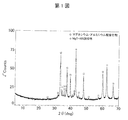
- FIG. 1 is an XRD analysis chart of Experimental Example 1.
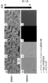
- FIG. 2 is an EPMA element mapping image of Experimental Examples 1 and 4.
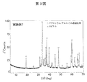
- FIG. 3 is an XRD analysis chart of Experimental Example 7.
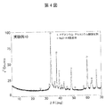
- FIG. 4 is an XRD analysis chart of Experimental Example 10.
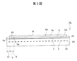
- FIG. 5 is a diagram schematically showing a heating apparatus 1A according to the embodiment of the present invention.
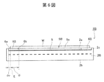
- FIG. 6 is a diagram schematically showing a heating device 1B according to the embodiment of the present invention.
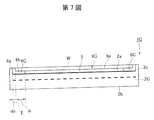
- FIG. 7 is a diagram schematically showing a heating apparatus 1C according to the embodiment of the present invention.
- FIG. 8 is a diagram schematically showing the state of plasma on the heating apparatus 1B according to the embodiment of the present invention.
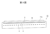
- FIG. 9 is a diagram schematically showing a heating device 11 of a reference example.
- the novel ceramic material used in the present invention will be described, and then the configuration of the heating apparatus will be described.
- the main phase is a nitride phase.
- the ceramic material of the present invention has a corrosion resistance equivalent to or higher than that of spinel. For this reason, the susceptor of the present invention can withstand a halogen-based plasma such as F and Cl having high reactivity used in a semiconductor manufacturing process for a long period of time, and can reduce the amount of dust generated from this member. In addition, even if it is used for a long time in a corrosive environment, it is difficult for the surface state to change due to corrosion, and as a result, good temperature uniformity on the wafer is exhibited over a long period of time.
- this magnesium-aluminum oxynitride has the same or higher corrosion resistance to halogen-based plasma than spinel, it is considered that the ceramic material of the present invention containing this oxynitride as the main phase also has higher corrosion resistance. Further, this magnesium-aluminum oxynitride may have a linear thermal expansion coefficient lower than that of spinel while having corrosion resistance equivalent to that of spinel.
- the ceramic material of the present invention may contain a crystal phase of MgO—AlN solid solution in which aluminum nitride is dissolved in magnesium oxide as a subphase. Since this MgO-AlN solid solution also has high corrosion resistance, there is no problem even if it is included as a subphase.
- the ceramic material of the present invention tends to decrease the corrosion resistance when an AlN crystal phase is included as a secondary phase. It is more preferable. Moreover, since spinel has higher corrosion resistance than alumina and AlN crystal, it may contain a small amount.
- the spinel is preferably less.
- a small amount of spinel or AlN crystal phase may be contained.
- the ceramic material of the present invention preferably has a magnesium / aluminum molar ratio of 0.20 to 2 in order to obtain corrosion resistance equivalent to or higher than that of spinel. The ratio is more preferably 0.75 or more and 2 or less.
- the magnesium / aluminum molar ratio is less than 0.20, the amount of any one of aluminum nitride, spinel, and aluminum oxide increases, and there is a concern that high corrosion resistance characteristics may be lost. If the magnesium / aluminum molar ratio exceeds 2, the MgO—AlN solid solution tends to be the main phase.
- the molar ratio of magnesium / aluminum in the raw material powder is preferably 0.05 or more and 1.5 or less. The molar ratio is more preferably 0.1 or more and 1 or less.
- the open porosity is preferably 5% or less.
- the open porosity is a value measured by the Archimedes method using pure water as a medium. If the open porosity exceeds 5%, the strength may be reduced, or the material itself may be likely to generate dust by degreasing, and further, dust generation components are likely to accumulate in the pores during material processing or the like, which is not preferable.
- the open porosity is preferably as close to zero as possible. For this reason, there is no lower limit in particular.
- the linear thermal expansion coefficient at 40 to 1000 ° C. of the magnesium-aluminum oxynitride forming the main phase is 6 to 7 ppm / K.
- MgO-AlN solid solution (12 to 14 ppm / K), spinel (8 to 9 ppm / K), and aluminum nitride (5 to 6 ppm / K) as subphase components, high corrosion resistance is maintained.
- the linear thermal expansion coefficient can be controlled to 5.5 to 10 ppm / K.
- spinel and aluminum nitride have lower corrosion resistance than magnesium-aluminum oxynitride and MgO-AlN solid solution, it is preferable that there be less.
- the thermal expansion with the material used as a semiconductor manufacturing apparatus member such as aluminum oxide, yttrium oxide, and aluminum nitride can be matched, or the thermal expansion difference can be reduced.
- the ceramic material of the present invention and the conventional material can be laminated and bonded. If it carries out like this, only the surface (1st structure) can be made into the ceramic material which has the high corrosion resistance of this invention, and a conventional material can be used for the base material of a lower part (2nd structure).
- a laminated structure and thermal expansion adjustment are effective in integral sintering.
- a material mainly composed of aluminum nitride for the base material of the second structure high thermal conductivity can be maintained, and the surface temperature of the ceramic material having high corrosion resistance can be easily maintained.
- Such a configuration is particularly effective in a semiconductor manufacturing apparatus with a built-in heater.
- the ceramic material of the present invention is used for a laminate having a first structure using the above-described ceramic material and a second structure having a main phase of at least one of aluminum nitride, yttrium oxide, and aluminum oxide. It may be a thing. Further, the first structure and the second structure may be laminated or bonded. In this way, the first structure having high corrosion resistance and the second structure having characteristics different from the first structure (for example, heat conductivity, mechanical strength, etc.) can enhance other characteristics in addition to the corrosion resistance. Can do.
- the first structure may be a thin film, a plate-like body, or a layered body formed of the ceramic material.
- the second structure may be a thin film, a plate-like body, or a layered body having aluminum nitride, yttrium oxide, and aluminum oxide as a main phase.
- it may join by sintering and may be joined by the adhesive agent.
- the first structure and the second structure may be joined via an intermediate layer.
- the intermediate layer can further suppress, for example, separation between the first structure and the second structure due to a difference in thermal expansion coefficient.
- This intermediate layer may be a layer having intermediate properties between the first structure and the second structure.
- This intermediate layer may be, for example, a layer in which the main phase of the first structure and the main phase of the second structure are mixed.
- the intermediate layer may include a plurality of layers having different components or component ratios. By doing so, it is possible to obtain a gradient material characteristic.
- the linear thermal expansion coefficient difference between the first structure and the second structure is 0.3 ppm / K or less, and the first structure and the second structure may be directly joined. In this way, since the difference in coefficient of linear thermal expansion between the first structure and the second structure is small, both structures are bonded at high temperature (for example, bonded by sintering) or when this laminate is heated at high to low temperatures. There is no risk of cracking or peeling when repeated use.
- the ceramic material of the present invention can be produced by firing a mixed powder of magnesium oxide, alumina, and aluminum nitride after forming.
- magnesium oxide is 15 mass% or more and 66.2 mass% or less, alumina is 63 mass% or less, and aluminum nitride is 57.7 mass% or less.
- the mixed powder may be fired after molding. Further, a powder in which magnesium oxide is mixed in an amount of 37 mass% to 66.2 mass%, alumina is 63 mass% or less, and aluminum nitride is 57.7 mass% or less may be formed and fired.
- magnesium oxide is 5 mass% to 60 mass%
- alumina is 60 mass% or less
- aluminum nitride is 90 mass%.
- the firing temperature is preferably 1750 ° C. or higher.
- a firing temperature of less than 1750 ° C. is not preferable because the intended magnesium-aluminum oxynitride may not be obtained.
- the upper limit of baking temperature is not specifically limited, For example, it is good also as 1850 degreeC or 1900 degreeC.
- the heating device of the present invention includes a susceptor portion having a heating surface for heating a semiconductor, and a ring-shaped portion provided on the outer periphery of the heating surface, and the ring-shaped portion is made of the ceramic material.
- the heating apparatus 1A of FIG. 5 includes a susceptor portion 9A and a ring-shaped portion 6A.
- the base 2A of the susceptor portion 9A has a plate shape, and the dielectric layer 5 is formed on the upper surface 2a side of the base 2A.
- the upper surface of the dielectric layer 5 forms the semiconductor heating surface 9a.
- the heating surface 9a does not need to be flat, and uneven processing may be performed, a groove matching the size of the substrate may be formed, or a groove for purge gas may be formed. You may join the support part which is not shown in figure to the lower surface (back surface) 2b of a susceptor.
- the support portion is, for example, tubular, and houses the power supply member in the support portion.
- the power supply member is connected to the heating element 3 embedded in the susceptor base 2A.
- the susceptor portion 9A has a disk shape, preferably a substantially disk shape.
- the size of the susceptor is not particularly limited.
- the susceptor has a diameter of 280 to 380 mm and a thickness of 8 to 20 mm.
- the heating element 3 is preferably embedded in the susceptor portion 9A, but may be attached to the susceptor portion.
- the heating element may be an external heating element such as an infrared heating element provided at a position away from the susceptor part.
- An electrode 4 is embedded in the base portion 2A of the susceptor.
- the electrode 4 is preferably a plasma generating electrode for applying a high frequency voltage to generate plasma.
- the ring-shaped portion 6A of the present invention is provided so as to surround the outer periphery of the susceptor portion 9A, and the semiconductor W is placed on the dielectric layer 5 and the ring-shaped portion 6A.
- the ring-shaped portion extends to the outer peripheral edge of the susceptor portion, and no protrusion is provided on the outer peripheral edge of the susceptor portion.
- the inner peripheral side of the ring-shaped portion 6A is a mounting portion 6b existing under the semiconductor W, and the outer peripheral side is exposed to the outside of the semiconductor W outside the mounting portion 6b.
- the mounting portion 6a is formed.
- the non-mounting part 6a surrounds the semiconductor W in a plan view.
- the ring-shaped portion 6B does not extend to the outer peripheral edge of the susceptor portion 9B (base 2B), and the ring-shaped protrusion 2c is formed on the susceptor portion 9B.
- the protrusion 2c surrounds the outer peripheral edge of the ring-shaped portion 6B when viewed in a plan view.
- the ring-shaped portion 6C does not extend to the outer peripheral edge of the susceptor portion 9C, and the ring-shaped protrusion 2c is formed on the susceptor portion 9C (base 2C).
- the protrusion 2c surrounds the outer peripheral edge of the ring-shaped portion 6C when viewed in plan.
- the non-mounting portion 6 a is further formed of a ring-shaped protrusion that surrounds the outer peripheral edge of the semiconductor W.
- the film thickness T is distributed as schematically shown in FIG. That is, the film thickness T is decreased as shown by T1 on the inner side of the edge E of the semiconductor W.
- a ring-shaped member made of the ceramic material of the present invention a region where the film thickness decreases, such as T2, shifts to the outer peripheral side.
- the heating element 3 and the high frequency electrode 4 are embedded inside the susceptor 11.
- the semiconductor W is placed on the heating surface 11 a of the susceptor 11.
- the entire susceptor 11 is formed of, for example, aluminum nitride
- the film formation uniformity is deteriorated on the outer peripheral side of the semiconductor.
- the inner peripheral side of the ring-shaped portion is a mounting portion 6b positioned below the semiconductor W
- the outer peripheral side is a non-mounting portion 6a positioned outside the semiconductor W.
- the width di of the mounting portion 6b is preferably 0 mm or more, and more preferably 10 mm or more. Further, di is preferably 50 mm or less, and more preferably 30 mm or less. Further, from the viewpoint of improving the film formation uniformity, the width do of the non-mounting portion 6a is preferably 0 mm or more, and more preferably 15 mm or more.
- di is a planar dimension from the edge E of the semiconductor W to the inner peripheral edge of the mounting portion 6b, and do is a planar dimension from the edge E of the semiconductor W to the outer peripheral edge of the non-mounting portion 6a. is there.
- the heating device includes a heating element embedded in the susceptor part and a high-frequency generating electrode embedded in the susceptor part.
- the support part joined to the back surface of a susceptor is provided.
- MgO-AlN solid solution (12 to 14 ppm / K), spinel (8 to 9 ppm / K), and aluminum nitride (5 to 6 ppm / K) as subphase components, high corrosion resistance is maintained.
- the linear thermal expansion coefficient can be controlled to 5.5 to 10 ppm / K.
- spinel and aluminum nitride have lower corrosion resistance than magnesium-aluminum oxynitride and MgO-AlN solid solution, it is preferable that there be less.
- By adjusting the thermal expansion it is possible to reduce the thermal expansion difference from materials used as semiconductor manufacturing apparatus members such as aluminum oxide, yttrium oxide, and aluminum nitride.
- the ceramic material of the present invention and the conventional material can be laminated and bonded.
- the material of the susceptor part include aluminum oxide, yttrium oxide, aluminum nitride, magnesium oxide, silicon nitride, and spinel, and aluminum oxide, yttrium oxide, and aluminum nitride are particularly preferable.
- the susceptor portion by forming the susceptor portion with a material having aluminum nitride as the main phase, high thermal conductivity can be maintained and temperature uniformity on the wafer can be easily maintained.
- the joining method of a susceptor part and a ring-shaped member is not specifically limited. Both may be joined by, for example, integral sintering, or may be joined by an adhesive.
- the difference in coefficient of linear thermal expansion between the susceptor part and the ring-shaped part is 0.3 ppm / K or less.
- the susceptor portion and the ring-shaped portion may be joined via the intermediate layer. In this way, for example, peeling of the ring-shaped portion due to a difference in thermal expansion coefficient can be further suppressed.
- the intermediate layer is a layer having intermediate properties between the susceptor portion and the ring-shaped portion.
- the intermediate layer may be a composite ceramic obtained by sintering a mixture of the ceramic material and the susceptor material.
- a plurality of intermediate layers can be formed, and the gradient material layer can be formed by making the compositions of the intermediate layers different from each other.
- the heating element for example, a linear conductor bent and processed into a wound body can be used.
- the wire diameter of the heating element is about 0.3 mm to 0.5 mm. In the case of a coil shape, the winding diameter is about 2 mm to 4 mm, and the pitch is about 1 mm to 7 mm.
- the “winding diameter” means the inner diameter of the coil constituting the heating element.
- the shape of the heating element various forms such as a ribbon shape, a mesh shape, a coil spring shape, a sheet shape, and a printed electrode can be adopted in addition to the coil shape. Note that it is desirable to perform pattern deformation as necessary, such as by bypassing the heating element 12 in a portion adjacent to a lift pin or the like and a through hole provided for purge gas.
- a high melting point conductive material such as molybdenum (Mo), tungsten (W), niobium (Nb), or the like can be preferably used.
- the above-mentioned heating element material can be used.
- the material of the support portion (so-called shaft) is not necessarily limited, and the following can be exemplified.
- the material of the support part is also the same ceramic material as the susceptor part.
- the ceramic material forming the susceptor part and the ceramic material forming the support part do not need to have the same composition, and may have different compositions.
- the ring-shaped part of the present invention is excellent in corrosion resistance against halogen-based corrosive gas and plasma thereof, and particularly has excellent corrosion resistance against the following halogen-based corrosive gas or a mixture thereof or plasma thereof.
- Experimental Examples 1 to 3 and 6 to 16 correspond to examples of the present invention, and Experimental Examples 4, 5, and 17 to 19 correspond to comparative examples.
- the compounded powder was uniaxially pressed at a pressure of 200 kgf / cm 2 to produce a disk-shaped molded body having a diameter of about 35 mm and a thickness of about 10 mm, and stored in a firing graphite mold.
- -Firing A ceramic material was obtained by hot-press firing the disk-shaped compact. In hot press firing, the press pressure was 200 kgf / cm 2 , firing was performed at the firing temperature (maximum temperature) shown in Table 1, and an Ar atmosphere was maintained until firing was completed. The holding time at the firing temperature was 4 hours.
- Example 4 A ceramic material was obtained in the same manner as in Experimental Example 1 except that the MgO raw material and the Al 2 O 3 raw material were weighed so as to have the mass% shown in Table 1.
- Example 5 A ceramic material was obtained in the same manner as in Experimental Example 1 except that the firing temperature was set to 1650 ° C.
- Example 6 to 12 The ceramic material was measured in the same manner as in Experimental Example 1 except that the MgO raw material, the Al 2 O 3 raw material, and the AlN raw material were weighed so as to have the mass% shown in Table 1 and the firing temperature was changed to the temperature shown in Table 1. Obtained.
- test piece was 50 mm in diameter (0.5 to 1 mm), each electrode was formed of silver so that the main electrode had a diameter of 20 mm, the guard electrode had an inner diameter of 30 mm, an outer diameter of 40 mm, and the applied electrode had a diameter of 40 mm.
- the applied voltage was 2 kV / mm, the current value at 1 minute after the voltage application was read, and the room temperature volume resistivity was calculated from the current value.
- Experimental Example 7 and Experimental Example 19 (MgO sintered body) were measured at 600 ° C. under vacuum (0.01 Pa or less).
- the shape of the test piece was 50 mm in diameter (0.5 to 1 mm), each electrode was formed of silver so that the main electrode had a diameter of 20 mm, the guard electrode had an inner diameter of 30 mm, an outer diameter of 40 mm, and the applied electrode had a diameter of 40 mm.
- the applied voltage was 500 V / mm, the current value at 1 hour after voltage application was read, and the volume resistivity was calculated from the current value.
- “aEb” represents a ⁇ 10 b
- “1E16” represents 1 ⁇ 10 16 .
- FIG. 1 shows an XRD analysis chart of Experimental Example 1.
- Table 1 summarizes the crystal phases detected in Experimental Examples 1 to 19.
- the XRD analysis charts of the ceramic materials of Experimental Examples 1 to 3 show a plurality of peaks ( ⁇ in FIG. 1) that cannot be identified and a peak of MgO—AlN solid solution in which aluminum nitride is dissolved in magnesium oxide ( 1).
- FIG. 2 shows an EPMA element mapping image of Experimental Example 1. 2, it is confirmed that Experimental Example 1 is composed of two phases of the magnesium-aluminum oxynitride (x part) and the MgO—AlN solid solution (y part) shown in FIG. 1, and the former is the main phase. I understood that.
- the main phase refers to a component having a volume ratio of 50% or more
- the subphase refers to a phase in which an XRD peak is identified other than the main phase. Since the area ratio in the cross-sectional observation is considered to reflect the volume ratio, the main phase is a region having an area of 50% or more in the EPMA element mapping image, and the subphase is a region other than the main phase. From FIG. 2, it was found that the area ratio of magnesium-aluminum oxynitride was about 66%, and magnesium-aluminum oxynitride was the main phase.
- the basis for specifying that the x part is magnesium-aluminum oxynitride is composed of four components of Mg, Al, O, and N, and Mg and N compared to the spinel material (z part) of Experimental Example 4 This is because the concentration was high, the Al concentration was about the same, and the O concentration was low. That is, this magnesium-aluminum oxynitride is characterized by containing more Mg than spinel.
- the determination of the main phase and the subphase is performed by EPMA element mapping.
- EPMA element mapping image is color-coded into red, orange, yellow, yellow green, green, blue, and indigo according to the concentration. Red represents the highest concentration, indigo represents the lowest concentration, and black represents zero.
- FIG. 2 is displayed in monochrome, the original colors in FIG. 2 will be described below.
- Mg is yellow-green in the x part and red in the y part
- Al is orange in the x part and blue in the y part
- N is orange in the x part and blue in the y part
- O is light blue in the x part.
- Mg was green as a whole (z portion)
- Al was orange as a whole
- N was black as a whole
- O was red as a whole.
- the ceramic material contained spinel (MgAl 2 O 4 ) as the main phase.
- FIG. 3 shows an XRD analysis chart of Experimental Example 7
- FIG. 4 shows an XRD analysis chart of Experimental Example 10.
- Experimental Example 10 was found to have MgO—AlN solid solution ( ⁇ in the figure) as a subphase.
- the XRD analysis chart is not shown, and the main phase and subphase are shown in Table 1.
- the etching rates of the ceramic materials of Experimental Examples 1 to 3 and 6 to 8 are as low as 80% or less of Experimental Example 4, and the etching rates of Experimental Examples 9 to 12 are as low as 90% or less of Experimental Example 4. It was found that the corrosion resistance was very high. Since Experimental Example 5 contained a lot of spinel and aluminum nitride having low corrosion resistance, the etching rate was high. Note that the etching rate of alumina shown in Experimental Example 18 is higher than that of the ceramic material (spinel) of Experimental Example 4. In addition, the ceramic materials of Experimental Examples 1 to 3 and 6 to 8 have sufficiently high values for bending strength and volume resistivity.
- the etching rate at high temperature was also measured.
- the surface of each material was polished to a mirror surface and subjected to a corrosion resistance test at a high temperature under the following conditions using an ICP plasma corrosion resistance test apparatus. Then, the etching rate of each material was calculated by dividing the step between the mask surface and the exposed surface measured by the step meter by the test time. As a result, the etching rate of each material was 1/3 or less that of alumina, 1/5 or less that of aluminum nitride, and the same level as spinel, and the plasma corrosion resistance at high temperatures was also good.
- Experimental Example 17 the raw material composition was the same as that in Experimental Example 6, but since the firing temperature was low, spinel became the main phase instead of magnesium-aluminum oxynitride, so the corrosion resistance was lower than in Experimental Example 6. With this, the coefficient of linear thermal expansion increased.
- the ceramic material having a magnesium-aluminum oxynitride phase as a main phase has a lower electrical resistance than MgO. From the above, the ceramic materials produced in Experimental Examples 1 to 3 and 6 to 16 are also expected to have an electrical resistance lower than that of magnesium oxide. 2. Laminated Sintering Next, laminated bodies obtained by laminating and sintering the first structure and the second structure using the above-described ceramic material will be described (Experimental Examples 20 to 26). Experimental examples 20 to 24 correspond to examples of the present invention, and experimental examples 25 and 26 correspond to comparative examples. [Experimental Examples 20 and 21] In the ceramic materials of Experimental Examples 4 and 6 to 12, the average linear thermal expansion coefficient at 40 to 1000 ° C. was 7 to 9 ppm / K.
- the ceramic material of Experimental Example 10 is used as the first structure
- aluminum nitride is used as the second structure
- the first and second structures are stacked to have a diameter of 50 mm.
- Lamination sintering was performed on the sample molded into the above.
- yttrium oxide is added as a sintering aid in an amount of 5% by mass (that is, added at a ratio of 5 parts by mass of Y 2 O 3 to 100 parts by mass of AlN, referred to as AlN [1]).
- 50% by mass added that is, added at a ratio of 50 parts by mass of Y 2 O 3 to 100 parts by mass of AlN, referred to as AlN [2]).
- the aluminum nitride and yttrium oxide raw materials commercially available products having a purity of 99.9% by mass or more and an average particle size of 1 ⁇ m or less were used.
- the AlN raw material it is inevitable that oxygen is contained in an amount of about 1% by mass, and the purity is obtained by removing oxygen from the impurity element.
- the average linear thermal expansion coefficient of 40 to 1000 ° C. is 5.7 ppm / K for AlN [1] and 6.2 ppm / K for AlN [2]
- the first structure and the second structure There is a difference in thermal expansion between the two.
- an intermediate layer in which AlN [1] or AlN [2] and the raw material of Experimental Example 10 are mixed is provided between the first structure and the second structure.
- This intermediate layer can alleviate the difference in thermal expansion.
- the intermediate layer has three layers mixed at a mass ratio of 25:75, 50:50, and 75:25, and in Experimental Example 21 using AlN [2], the intermediate ratio is 40. : 60, 60:40 mixed to form two layers.
- molding, and baking is explained in full detail.
- AlN [1] of the second structure first, aluminum nitride powder and yttrium oxide powder are weighed at a ratio of 100% by mass and 5.0% by mass, using isopropyl alcohol as a solvent, a nylon pot, and a nylon cobblestone. For 4 hours. After mixing, the slurry was taken out and dried at 110 ° C. in a nitrogen stream. Thereafter, the mixture was passed through a 30-mesh sieve to obtain a mixed powder. Furthermore, the obtained blended powder was heat-treated at 450 ° C. for 5 hours or more in the air atmosphere, and the carbon components mixed during the wet mixing were removed by burning.
- the intermediate layer of the laminate using AlN [1] was prepared as follows.
- the blended powder of Experimental Example 10 and the blended powder of the above-mentioned aluminum nitride were weighed at a mass ratio of 75:25 (intermediate layer 1), 50:50 (intermediate layer 2), and 25:75 (intermediate layer 3). Then, using isopropyl alcohol as a solvent, the mixture was wet-mixed for 4 hours using a nylon pot and nylon cobblestone. After mixing, the slurry was taken out and dried at 110 ° C. in a nitrogen stream. Thereafter, it was passed through a 30-mesh sieve to obtain a mixed powder.
- AlN [2] of the second structure aluminum nitride powder and yttrium oxide powder were prepared in the same manner as AlN [1] except that they were weighed at a ratio of 100% by mass and 50% by mass. Further, the intermediate layer of the laminate using AlN [2] has a mass ratio of 60:40 (intermediate layer 1) and 40:60 (intermediate layer 2) of the prepared powder of Experimental Example 10 and the prepared powder of aluminum nitride described above.
- the mixture was prepared in the same manner as in the case of AlN [1] except that it was weighed at a ratio of -Molding First, aluminum nitride mixed powder as a raw material of the second structure was filled in a metal mold having a diameter of 50 mm, and uniaxial pressure molding was performed at a pressure of 200 kgf / cm 2 .
- the aluminum nitride molded body was not die-cut, and the upper portion was filled with the mixed powder of the intermediate layer in descending order of the aluminum nitride ratio, and uniaxially pressure-molded for each filling at a pressure of 200 kgf / cm 2 .
- the blended powder of Experimental Example 10 which is a raw material of the first structure was filled, and pressure molding was performed at 200 kgf / cm 2 .
- a disk of 23 mm in total consisting of an aluminum nitride layer of the second structure of 10 mm, an intermediate layer of 1 mm ⁇ 3 layers, and a layer of Example 10 of the first structure of 10 mm A shaped molded body was obtained.
- the aluminum nitride layer of the second structure is 10 mm
- the intermediate layer is 1 mm ⁇ 2 layers
- the layer of Experimental Example 10 of the first structure is 10 mm, for a total of 22 mm.
- the laminated disk-shaped compacts were stored in a firing graphite mold.
- -Firing A disc-shaped molded body housed in a firing graphite mold was hot-press fired to obtain an integrally fired ceramic material.
- the press pressure was 200 kgf / cm 2
- firing was performed at a firing temperature of 1800 ° C.
- an Ar atmosphere was maintained until the firing was completed.
- the holding time at the firing temperature was 4 hours.
- baking was also performed at a baking temperature of 1750 ° C. (Experimental Examples 20-1 and 211-1).
- the sintered body obtained by the above-described manufacturing method includes a laminate using AlN [1] (Experimental Examples 20 and 20-1) and a laminate using AlN [2] (Experimental Examples 21 and 21-1).
- the upper part is composed of a highly corrosion-resistant magnesium-aluminum oxynitride
- the lower part of the sintered body is composed of a sintered body mainly composed of highly heat-conductive aluminum nitride, and an intermediate layer is disposed therebetween.
- the intermediate layer is inclined so that the content of AlN becomes higher as it approaches the second structure from the first structure.
- the thermal stress generated between the base material and the magnesium-aluminum oxynitride was reduced, and the intermediate layer could be made thin.
- a sintered body is presumed to be suitably used, for example, as a member for semiconductor manufacturing equipment such as an electrostatic chuck, a susceptor, a heater, a plate, an inner wall material, a monitoring window, a microwave introduction window, and a microwave coupling antenna. It was done.
- Experimental Example 22 as shown in Table 2, the experiment was performed except that the ceramic material of Experimental Example 6 was the first structure and aluminum oxide was the second structural body, and was laminated and sintered in an N 2 atmosphere without an intermediate layer.
- a laminate was obtained in the same manner as in Example 20.
- Experimental Example 23 as shown in Table 2, the experiment was performed except that the ceramic material of Experimental Example 6 was the first structure, the yttrium oxide was the second structure, and was laminated and sintered in an N 2 atmosphere without an intermediate layer.
- a laminate was obtained in the same manner as in Example 20.
- Experimental Example 24 as shown in Table 2, the ceramic material of Experimental Example 13 was the first structure, and aluminum nitride (AlN [1]) was the second structure, and was laminated and sintered in an N 2 atmosphere without an intermediate layer.
- AlN [1] aluminum nitride
- a laminated body was obtained in the same manner as in Experimental Example 20 except that. In any of Experimental Examples 22 to 24, no cracks or cracks were observed between the layers.
- Experimental Example 25 As shown in Table 2, it was the same as Experimental Example 20 except that alumina was the first structure, aluminum nitride (AlN [1]) was the second structure, and layered and sintered in an N 2 atmosphere. Thus, a laminate was obtained.
- Experimental Example 26 is the same as Experimental Example 20 except that the spinel is the first structure, the aluminum nitride (AlN [1]) is the second structure, and is laminated and sintered in an N 2 atmosphere. Thus, a laminate was obtained. In both Experimental Examples 25 and 26, cracks occurred between the layers.
- (B) Adjust the material of the ring-shaped part.
- the material constituting the ring-shaped part specifically, MgO raw material, Al2O3 raw material and AlN raw material were weighed, and wet mixed for 4 hours using a pot made of nylon and an alumina cobblestone having a diameter of 5 mm using isopropyl alcohol as a solvent.
- a mixing method for example, a large ball mill device in which a container itself called a trommel rotates is used. After mixing, the slurry was taken out and dried at 110 ° C. in a nitrogen stream. Thereafter, it was passed through a 30-mesh sieve to obtain a mixed powder.
- the molar ratio of Mg / Al of this mixed powder is 1.2.
- an aluminum nitride ceramic powder is mixed with a molding binder.
- the mixing time by the trommel is about 30 minutes, for example.
- granulation is performed by a granulator such as a spray dryer (SD) to obtain granulated powder.
- SD spray dryer
- the obtained granulated powder for the susceptor part is molded under uniaxial pressure by a mechanical press, and then the powder mixture for the ring-shaped part is added to a predetermined location, and again under uniaxial pressure by a mechanical press. To produce a preliminary molded body.
- the molded body produced as described above is placed in a firing furnace such as a hot press system and subjected to integral firing.
- Hot press is a method in which raw material powder or compact is filled or inserted into a carbon jig and fired under a uniaxial pressure of 30 to 50 MPa. It is a ceramic material that is difficult to be densified by normal atmospheric pressure sintering. Suitable for firing.
- the firing conditions at this time are a firing temperature of 1600 ° C. to 2000 ° C., a pressure of 100 to 300 kg / cm 2 , and a firing time of 2 to 5 hours.
- a shaft is provided on the back side of the susceptor.
- the shaft portion is manufactured separately from the plate.
- the material of the shaft is adjusted. Specifically, a mixed powder is obtained in the same manner as the material adjustment of the aluminum nitride ceramics constituting the susceptor portion of the plate.
- the obtained blended powder is put into a firing furnace such as a cold isostatic press (Cold Isostatic Pressing, CIP) and fired to produce a molded body.
- CIP is a method in which an isotropic pressure molding process is performed on a uniaxial molded body obtained by a mold molding method, and improvement and unevenness of the molded body density can be eliminated.
- the shaft compact thus obtained is fired in a normal pressure firing furnace or the like.
- the firing conditions at this time are a firing temperature of 1600 ° C. to 2000 ° C., a pressure of 1 to 30 kg / cm 2 , and a firing time of 1 to 5 hours.
- the plate and shaft obtained by the above procedure are joined in a firing furnace by the direct bond method.
- the firing conditions at this time are a firing temperature of 1400 ° C. to 2000 ° C., a pressure of 100 to 300 kg / cm 2 , and a firing time of 2 to 5 hours.
- the ring-shaped protrusion 6a is formed on the outer periphery of the ring-shaped part, and the ring-shaped protrusion 2c is formed on the outer periphery of the susceptor part.
- the ring-shaped protrusion 6a is formed on the outer periphery of the ring-shaped portion, but the ring-shaped portion extends to the outer peripheral edge of the susceptor portion.
- the ring-shaped protrusion 2c is not formed on the outer periphery of.
- a susceptor as shown in FIG. 7 is manufactured. However, the ring-shaped portion extends to the outer peripheral edge of the susceptor portion, and no ring-shaped protrusion 2c is formed on the outer periphery of the susceptor portion.
- the material of the susceptor is only aluminum nitride.
- a susceptor as shown in FIG. 9 is manufactured.
- a susceptor as shown in FIG. 7 is manufactured.
- the ring-shaped portion extends to the outer peripheral edge of the susceptor portion, and the ring-shaped protrusion 2c is not formed on the outer periphery of the susceptor portion.
- the material of the susceptor is only the ceramic material having MgAlON as the main phase.
- Corrosion resistance test: ICP: 800 W, bias: 450 W, introduced gas: NF 3 / O 2 / Ar 75/35/100 sccm, 0.05 Torr, exposure time: 100 hrs.
- the outer peripheral film forming range is defined as a maximum or minimum difference in film forming thickness within a range of R140 to R147 mm.
- the material having Mg—Al—O—N as the main phase used in each experimental example in the following table has the composition of Experimental Example 12 in the above-described Examples (Table 1).
- Table 1 The composition of Experimental Example 12 in the above-described Examples (Table 1).
- Experiment No. which is an embodiment of the present invention.
- the film-forming range before the corrosion resistance test is small, and the film-forming range is kept extremely small even after the corrosion resistance test.
- the susceptor is made of aluminum nitride, but the film forming range is large both before and after the corrosion resistance test.
- the susceptor is composed only of the ceramic material having MgAlON as the main phase, but has high corrosion resistance and does not deteriorate the film-forming range even after the corrosion resistance test.
- the film formation range before the corrosion resistance test is the experiment No. It is inferior to 1-C and 2-C.
Landscapes
- Chemical & Material Sciences (AREA)
- Engineering & Computer Science (AREA)
- Ceramic Engineering (AREA)
- Manufacturing & Machinery (AREA)
- Materials Engineering (AREA)
- Organic Chemistry (AREA)
- Structural Engineering (AREA)
- Inorganic Chemistry (AREA)
- Physics & Mathematics (AREA)
- Thermal Sciences (AREA)
- Chemical Kinetics & Catalysis (AREA)
- Mechanical Engineering (AREA)
- Metallurgy (AREA)
- Drying Of Semiconductors (AREA)
- Ceramic Products (AREA)
- Container, Conveyance, Adherence, Positioning, Of Wafer (AREA)
- Compositions Of Oxide Ceramics (AREA)
- Resistance Heating (AREA)
- Physical Vapour Deposition (AREA)
Abstract
Description
また、ウエハを加熱するために用いられるセラミックスヒーターが知られている。こうしたセラミックスヒーターにおいては、ウエハを均一に加熱できるよう、ヒーターの温度均一性が要求される。例えば、特許文献2(特開平8−73280)には、抵抗発熱体を窒化アルミニウム質セラミックスプレートに埋設し、窒化アルミニウム質のシャフトをプレートに接合したセラミックスヒーターが開示されている。特許文献3(特開2003−288975号公報)においては、シャフト付きのヒーターにおいて、更に抵抗発熱体における金属炭化物の量を少なくすることで、抵抗発熱体の場所ごとの炭化物量のばらつきを少なくして加熱面の温度分布を小さくすることが記載されている。
サセプター上に半導体ウエハを載置して成膜する場合には、特に半導体ウエハの外周部において成膜均一性が求められる。半導体製造装置内でSiウエハを保持し更に加温する部材として、上述のようにAlN(窒化アルミニウム)製のセラミックヒータが既存技術として広く用いられている。
また、プラズマエッチング装置としては、例えば、真空処理チャンバ内に、基板が載置される載置台を兼ねた下部電極と、この下部電極と対向するように配置された上部電極とが配置され、下部電極に高周波電力を供給して処理ガスのプラズマを発生させる構成のものが知られている。また、このような構成のプラズマエッチング装置において、基板の処理の面内均一性を向上させるため、下部電極の上に、基板の周囲を囲むようにフォーカスリングを設けた構成とすることが開示されている(特許文献4:特開2011−71464、特許文献5:特開2011−108816、特許文献6:特開2004−311837)。さらに、フォーカスリングの内部に誘導発熱部を設け、真空処理チャンバ内に設けた誘導コイルによって発生させる磁場により、フォーカスリングを誘導加熱することも知られている。
本発明の課題は、半導体の成膜に使用するセラミック加熱装置において、ウエハ外周部の成膜均一性を改善し、ハロゲン系腐食ガスまたそのプラズマ雰囲気下で使用したときにも半導体外周部の成膜均一性が長期間にわたって保持されるようにすることである。
本発明は、半導体を加熱する加熱面を有するサセプター部と、加熱面の外周に設けられているリング状部とを備えている加熱装置であって、
リング状部が、マグネシウム、アルミニウム、酸素及び窒素を主成分とするセラミックス材料からなり、このセラミックス材料が、CuKα線を用いたときのXRDピークが少なくとも2θ=47~50°に現れるマグネシウム−アルミニウム酸窒化物相を主相とすることを特徴とする。
また、本発明は、半導体を加熱する加熱面を有するサセプター上に設置されるリング状部であって、
リング状部が、マグネシウム、アルミニウム、酸素及び窒素を主成分とするセラミックス材料からなり、このセラミックス材料が、CuKα線を用いたときのXRDピークが少なくとも2θ=47~50°に現れるマグネシウム−アルミニウム酸窒化物相を主相とすることを特徴とする。
本発明によれば、前記セラミックス材料からなるリング状部を設けることで、半導体の周縁およびその周辺におけるプラズマの生成状態を安定化させることができ、成膜均一性を改善することができる。これと共に、前記セラミックス材料は、マグネシウム−アルミニウム酸窒化物相を主相としているが、窒化アルミニウムと比較して、ハロゲン系ガス等の腐食性の強いガスに対する耐食性に優れている。このセラミックス材料によってサセプターのリング状部を形成すると、腐食環境下で長く使用されても、腐食による表面状態の変化を生じにくく、この結果として半導体外周部における成膜均一性を長期間にわたって発現する事が可能となった。
図2は、実験例1,4のEPMA元素マッピング像である。
図3は、実験例7のXRD解析チャートである。
図4は、実験例10のXRD解析チャートである。
図5は、本発明の実施形態に係る加熱装置1Aを概略的に示す図である。
図6は、本発明の実施形態に係る加熱装置1Bを概略的に示す図である。
図7は、本発明の実施形態に係る加熱装置1Cを概略的に示す図である。
図8は、本発明の実施形態に係る加熱装置1B上のプラズマの状態を模式的に示す図である。
図9は、参考例の加熱装置11を概略的に示す図である。
[セラミックス材料]
本発明者らは、酸化マグネシウムとアルミナと窒化アルミニウムとの混合粉末を成形後ホットプレス焼成することにより得られるセラミックス材料の耐食性を鋭意検討したところ、特定位置にXRDピークを有するマグネシウム−アルミニウム酸窒化物を主相とするセラミックス材料が非常に高い耐食性を示すことを見いだした。
すなわち、本発明のセラミックス材料は、マグネシウム、アルミニウム、酸素及び窒素を主成分とするセラミックス材料であって、CuKα線を用いたときのXRDピークが少なくとも2θ=47~50°に現れるマグネシウム−アルミニウム酸窒化物相を主相とするものである。
本発明のセラミックス材料は、耐食性がスピネルと同等かそれよりも高い。このため、本発明のサセプターは、半導体製造プロセスにおいて使用される反応性の高いF、Cl等のハロゲン系プラズマに長期間耐えることができ、この部材からの発塵量を低減することができる。しかも,腐食環境下で長く使用されても、腐食による表面状態の変化を生じにくく、この結果として良好なウエハ上温度均一性を長期間にわたって発現する。
本発明のセラミックス材料は、マグネシウム、アルミニウム、酸素及び窒素を主成分とし、CuKα線を用いたときのXRDピークが少なくとも2θ=47~50°に現れるマグネシウム−アルミニウム酸窒化物相を主相とするものである。このマグネシウム−アルミニウム酸窒化物は、ハロゲン系プラズマに対する耐食性がスピネルと同等かそれより高いため、この酸窒化物を主相とする本発明のセラミックス材料も耐食性が高くなったと考えられる。また、このマグネシウム−アルミニウム酸窒化物は、スピネルと同等の耐食性を持ちながらスピネルよりも線熱膨張係数が低いものとすることもできる。
本発明のセラミックス材料は、酸化マグネシウムに窒化アルミニウムが固溶したMgO−AlN固溶体の結晶相を副相として含んでいてもよい。このMgO−AlN固溶体も耐食性が高いため、副相として含まれていても問題ない。このMgO−AlN固溶体は、CuKα線を用いたときの(200)面及び(220)面のXRDピークが酸化マグネシウムの立方晶のピークと窒化アルミニウムの立方晶のピークとの間である2θ=42.9~44.8°,62.3~65.2°に現れるものとしてもよく、更に、(111)面のXRDピークが酸化マグネシウムの立方晶のピークと窒化アルミニウムの立方晶のピークとの間である2θ=36.9~39°に現れるものとしてもよい。(111)面のピークが他の結晶相のピークとの判別を行いにくい場合があることから、(200)面及び(220)面のXRDピークのみ上記範囲に現れるものとしてもよい。同様に、(200)面または(220)面のピークも他の結晶相のピークとの判別を行いにくい場合がある。
本発明のセラミックス材料は、スピネルと同等かそれよりも高い耐食性を得るには、副相としてAlN結晶相を含むと耐食性が低下する傾向があるため、AlN結晶相は少ないことが好ましく、含まないことがより好ましい。また、スピネルは、アルミナやAlN結晶よりも耐食性が高いため、少量を含有してもよい。但し、スピネルは、本発明のマグネシウム−アルミニウム酸窒化物相、及びMgO−AlN固溶体よりも耐食性が劣るため、より少ないことが好ましい。一方、スピネルと同等の耐食性を持ちながら線熱膨張係数を低くするには、スピネルやAlN結晶相を少量含有していてもよい。
本発明のセラミックス材料は、スピネルと同等かそれよりも高い耐食性を得るには、原料粉末中のマグネシウム/アルミニウムのモル比が0.20以上2以下であることが好ましいが、マグネシウム/アルミニウムのモル比が0.75以上2以下であることがより好ましい。マグネシウム/アルミニウムのモル比が0.20未満であると窒化アルミニウム、スピネル、酸化アルミニウムのいずれかの生成量が多くなり、高耐食な特徴が失われることが懸念される。マグネシウム/アルミニウムのモル比が2を超えるとMgO−AlN固溶体が主相になりやすい。一方、スピネルと同等の耐食性を持ちながら線熱膨張係数を低くするには、原料粉末中のマグネシウム/アルミニウムのモル比が0.05以上1.5以下であることが好ましいが、マグネシウム/アルミニウムのモル比が0.1以上1以下であることがより好ましい。
本発明のセラミックス材料において、開気孔率は5%以下であることが好ましい。ここでは、開気孔率は、純水を媒体としたアルキメデス法により測定した値とする。開気孔率が5%を超えると、強度が低下するおそれや材料自身が脱粒によって発塵し易くなるおそれがあり、更に材料加工時等で気孔内に発塵成分がたまり易くなるため好ましくない。また、開気孔率は、できるだけゼロに近いほど好ましい。このため、特に下限値は存在しない。
本発明のセラミックス材料において、主相をなすマグネシウム−アルミニウム酸窒化物の40~1000℃の線熱膨張係数は、6~7ppm/Kである。そこで、副相成分のMgO−AlN固溶体(12~14ppm/K)や、スピネル(8~9ppm/K)、窒化アルミニウム(5~6ppm/K)の比率を変えることにより、高耐食性を維持したまま、線熱膨張係数を5.5~10ppm/Kに制御することができる。但し、スピネルや窒化アルミニウムは、マグネシウム−アルミニウム酸窒化物やMgO−AlN固溶体よりも耐食性が低いことから、より少ないことが好ましい。このような熱膨張の調整によって、酸化アルミニウム、酸化イットリウム及び窒化アルミニウムなど、半導体製造装置部材として用いられている材料との熱膨張を合わせる、または、熱膨張差を小さくすることができる。これによって、本発明のセラミックス材料と従来材料との積層や貼り合わせが可能となる。こうすれば、表面(第1構造体)のみを本発明の高い耐食性を有するセラミックス材料とし、下部(第2構造体)の基材に従来材料を使用することができる。特に、一体焼結においてこのような積層構造及び熱膨張調整は有効となる。なかでも、第2構造体の基材に窒化アルミニウムを主体とした材料を用いることにより、高熱伝導を維持することができ、高耐食であるセラミックス材料の表面温度を均一に保ちやすくなる。このような構成は、特にヒーター内蔵型の半導体製造装置において有効である。
本発明のセラミックス材料は、上述したセラミックス材料を利用した第1構造体と、窒化アルミニウム、酸化イットリウム及び酸化アルミニウムのうち少なくとも1種を主相とする第2構造体と、を有する積層体に用いるものとしてもよい。また、この第1構造体と第2構造体とが積層又は接合された構造を有するものとしてもよい。こうすれば、耐食性の高い第1構造体と、第1構造体と異なる特性(例えば伝熱性や機械的強度など)を有する第2構造体とにより、耐食性に加えて他の特性をより高めることができる。ここで、第1構造体は、上記セラミックス材料によって形成された薄膜や板状体、層状体としてもよい。また、第2構造体は、窒化アルミニウム、酸化イットリウム及び酸化アルミニウムを主相とする薄膜や板状体、層状体としてもよい。なお、接合はどのような態様で行われたものでもよく、例えば焼結により接合されていてもよいし、接着剤により接合されていてもよい。
このとき、第1構造体と第2構造体とが中間層を介して接合されていてもよい。こうすれば、中間層によって、例えば熱膨張率の違いによる第1構造体と第2構造体との剥離などをより抑制することができる。この中間層は、第1構造体と第2構造体との中間の性質を有する層としてもよい。この中間層は、例えば、第1構造体の主相と第2構造体の主相とを混合した層としてもよい。また、この中間層は、含有する成分、若しくは成分比の異なる複数の層を含むものとしてもよい。こうすれば、傾斜材料的な特性とすることができる。
また、第1構造体と第2構造体との線熱膨張係数差が0.3ppm/K以下であり、第1構造体と第2構造体とが直接接合されていてもよい。こうすれば、第1構造体と第2構造体との線熱膨張係数差が小さいため、両構造体を高温で接合(例えば焼結により接合)した際やこの積層体の高温−低温での使用を繰り返したりした際にクラックや剥離が生じるおそれがない。
[セラミックス材料の製造]
本発明のセラミックス材料は、酸化マグネシウムとアルミナと窒化アルミニウムとの混合粉末を、成形後焼成することにより製造することができる。例えば、スピネルと同等かそれよりも高い耐食性を得るには、酸化マグネシウムを15質量%以上66.2質量%以下、アルミナを63質量%以下、窒化アルミニウムを57.7質量%以下となるように混合した粉末を成形後焼成してもよい。更には、酸化マグネシウムを37質量%以上66.2質量%以下、アルミナを63質量%以下、窒化アルミニウムを57.7質量%以下となるように混合した粉末を成形後焼成してもよい。一方、スピネルと同等の耐食性を持ちながら線熱膨張係数を低くして温度均一性を高くするには、酸化マグネシウムを5質量%以上60質量%以下、アルミナを60質量%以下、窒化アルミニウムを90質量%以下となるように混合した粉末を成形後焼成してもよい。また、焼成温度は1750℃以上とすることが好ましい。焼成温度が1750℃未満では、目的とするマグネシウム−アルミニウム酸窒化物が得られないおそれがあるため好ましくない。なお、焼成温度の上限は、特に限定するものではないが、例えば1850℃とか1900℃としてもよい。また、焼成はホットプレス焼成を採用することが好ましく、ホットプレス焼成時のプレス圧力は、50~300kgf/cm2で設定することが好ましい。焼成時の雰囲気は、酸化物原料の焼成に影響を及ぼさない雰囲気であることが好ましく、例えば窒素雰囲気やアルゴン雰囲気、ヘリウム雰囲気などの不活性雰囲気であることが好ましい。成形時の圧力は、特に制限するものではなく、形状を保持することのできる圧力に適宜設定すればよい。
[加熱装置]
本発明の加熱装置は、半導体を加熱する加熱面を有するサセプター部と、加熱面の外周に設けられているリング状部とを備えており、リング状部が、前記のセラミックス材料からなる。
以下、適宜図面を参照しつつ述べる。
第5~8図は、本発明の実施形態に係るものである。
第5図の加熱装置1Aは、サセプター部9Aとリング状部6Aとを備えている。サセプター部9Aの基台2Aはプレート状であり、基台2Aの上面2a側に誘電体層5が形成されている。本例では、誘電体層5の上面が半導体加熱面9aをなしている。加熱面9aは平坦である必要はなく、凹凸加工を行ったり、基板の大きさにあわせた溝を形成したり、パージガス用の溝を形成しても良い。
サセプターの下面(背面)2bには、図示しない支持部を接合してもよい。支持部は例えば管状であり、支持部中に電力供給部材を収容する。電力供給部材は、サセプターの基台部2A内に埋設された発熱体3に接続する。
サセプター部9Aは盤状であり、好ましくは略円盤状である。サセプターの大きさは、特に限定するものではないが、例えば直径280~380mm、厚さ8~20mmである。
ここで、発熱体3は、サセプター部9A内に埋設されていることが好ましいが、サセプター部に取り付けられていても良い。また、発熱体は、サセプター部から離れた位置に設けられた赤外線加熱素子のような外部発熱体であってよい。
サセプターの基台部2A内には電極4が埋設されている。電極4は、好ましくは高周波電圧を印加してプラズマを生成させるためのプラズマ発生電極である。
サセプター部9Aの外周を包囲するように、本発明のリング状部6Aが設けられており、半導体Wは、誘電体層5上およびリング状部6A上に載置される。
本例では、リング状部は、サセプター部の外周エッジまで延びており、サセプター部の外周エッジには突起が設けられていない。また、半導体Wを設置した時点で、リング状部6Aの内周側は半導体W下に存在する載置部6bであり、外周側は載置部6bの外側で半導体W外に露出し、非載置部6aを形成する。非載置部6aは、半導体Wを平面的に見て包囲する。
第6図の加熱装置1Bにおいては、リング状部6Bがサセプター部9B(基台2B)の外周側エッジまで延びておらず、サセプター部9Bにリング状突起2cが形成されている。突起2cは平面的に見てリング状部6Bの外周エッジを包囲する。
また、第7図の加熱装置1Cにおいては、リング状部6Cがサセプター部9Cの外周側エッジまで延びておらず、サセプター部9C(基台2C)にリング状突起2cが形成されている。突起2cは平面的に見てリング状部6Cの外周エッジを包囲する。本例では、更に、非載置部6aが、半導体Wの外周エッジを包囲するリング状突起からなる。
従来は、第8図に模式的に示すように、成膜膜厚Tが分布していた。すなわち、膜厚Tは、半導体WのエッジEよりもかなり内側でT1のように減少していた。これに対して、本発明のセラミックス材料からなるリング状部材を用いることで、T2のように、膜厚が減少する領域が外周側にシフトする。
なお、第9図に示すような参考例のサセプター11の場合には、サセプター11の内側に発熱体3および高周波電極4を埋設する。そして、サセプター11の加熱面11a上に半導体Wを載置する。
このようなサセプター11の全体を例えば窒化アルミニウムによって形成した場合、やはり半導体の外周側で成膜均一性が劣化する。
更に、サセプター11の全体を、MgAlONを主相とする前記セラミックスで形成した場合には、高い耐蝕性が得られる一方、半導体の外周部における成膜均一性は改善されないことがわかった。
好適な実施形態においては、リング状部の内周側が半導体W下に位置する載置部6bであり、外周側が半導体W外に位置する非載置部6aである。このように設計することが、成膜均一性を改善する上で好適である。
この際、成膜均一性の改善という観点からは、載置部6bの幅diは、0mm以上であることが好ましく、10mm以上であることが更に好ましい。また、diは、50mm以下であることが好ましく、30mm以下であることが更に好ましい。
また、成膜均一性の改善という観点からは、非載置部6aの幅doは、0mm以上であることが好ましく、15mm以上であることが更に好ましい。
ただし、diは、半導体WのエッジEから載置部6bの内周側エッジまでの平面寸法であり、doは、半導体WのエッジEから非載置部6aの外周側エッジまでの平面寸法である。
サセプター部とリング状部との間に中間層を設けることで、リング状部の接合強度を向上させることができる。
また、好適な実施形態においては、加熱装置が、サセプター部の内部に埋設されている発熱体、およびサセプター部の内部に埋設されている高周波発生電極を備えている。
また、好適な実施形態においては、サセプターの背面に接合されている支持部を備えている。
[サセプター部および中間層の材質]
前記セラミックス材料において、主相をなすマグネシウム−アルミニウム酸窒化物の40~1000℃の熱膨張係数は、6~7ppm/Kである。そこで、副相成分のMgO−AlN固溶体(12~14ppm/K)や、スピネル(8~9ppm/K)、窒化アルミニウム(5~6ppm/K)の比率を変えることにより、高耐食性を維持したまま、線熱膨張係数を5.5~10ppm/Kに制御することができる。但し、スピネルや窒化アルミニウムは、マグネシウム−アルミニウム酸窒化物やMgO−AlN固溶体よりも耐食性が低いことから、より少ないことが好ましい。このような熱膨張の調整によって、酸化アルミニウム、酸化イットリウム及び窒化アルミニウムなど、半導体製造装置部材として用いられている材料との熱膨張差を小さくすることができる。これによって、本発明のセラミックス材料と従来材料との積層や貼り合わせが可能となる。
具体的には、サセプター部の材質は、酸化アルミニウム、酸化イットリウム、窒化アルミニウム、酸化マグネシウム、窒化珪素、スピネルを例示でき、酸化アルミニウム、酸化イットリウム、窒化アルミニウムが特に好ましい。
特に、窒化アルミニウムを主相とする材質によってサセプター部を形成することにより、高熱伝導を維持でき、ウエハ上温度均一性を保持しやすくなる。
サセプター部とリング状部材との接合方法は特に限定されない。両者は、例えば一体焼結により接合されていてもよいし、接着剤により接合されていてもよい。
こうした接着剤としては、シリコーン系接着剤、アクリル系接着剤、Al合金接着剤を例示できる。
好適な実施形態においては、サセプター部とリング状部との線熱膨張係数差が0.3ppm/K以下である。この場合には、両者を高温で接合(例えば一体焼結により接合)した際やこの積層体の高温−低温での使用を繰り返したりした際に、クラックや剥離が生じるおそれがない。
前述したように、サセプター部とリング状部とは、中間層を介して接合されていてもよい。こうすれば、例えば熱膨張率の違いによるリング状部の剥離を、いっそう抑制することができる。この中間層は、サセプター部とリング状部との中間の性質を有する層とする。
具体的には、中間層は、前記セラミックス材料と、サセプター部の材料との混合物を焼結した複合セラミックスであってよい。
また、中間層を複数層形成することができ、各中間層の組成を互いに異ならせることによって、傾斜材料層を形成することができる。
[発熱体および電極の材質]
発熱体は、例えば線状の導体を屈曲させ、巻回体に加工したものを使用可能である。発熱体の線径は0.3mm~0.5mm程度であり、コイル形状の場合には巻径は2mm~4mm程度であり、ピッチは1mm~7mm程度である。ここで「巻径」とは、発熱体を構成するコイルの内径を意味する。
発熱体の形状としては、コイル形状の他にも、リボン状、メッシュ状、コイルスプリング状、シート状、印刷電極等の種々の形態を採用することもできる。なお、リフトピン等やパージガス用に設けられた貫通孔に隣接する部分では、発熱体12を迂回させたりするなど、必要に応じてパターンの変形を行うことが望ましい。発熱体12の材料としては、モリブデン(Mo)、タングステン(W)、ニオブ(Nb)等の高融点導電材料を好ましく使用できる。
プラズマをサセプター上に発生させるための高周波電極および静電チャック電極の材質としては、前記の発熱体材料を利用できる。
[支持部の材質]
支持部(いわゆるシャフト)の材質は必ずしも限定はされず、以下を例示できる。
本出願の材料、窒化アルミニウム、酸化アルミニウム、酸化マグネシウム、スピネル
好ましくは、支持部の材質もサセプター部と同じセラミックス材料とする。ただし、この場合にも、サセプター部を形成する前記セラミックス材料と、支持部を形成する前記セラミックス材料とは、同一組成である必要はなく、互いに異なる組成であってよい。
[ハロゲン系腐食性ガス]
本発明のリング状部は、ハロゲン系腐食性ガスおよびそのプラズマに対する耐蝕性に優れているが、特に以下のハロゲン系腐食性ガスまたはその混合物またはこれらのプラズマに対する耐蝕性が特に優れている。
NF3、CF4、ClF3、Cl2、BCl3、HBr
以下に、本発明の好適な適用例について説明する。MgO原料、Al2O3原料及びAlN原料は、純度99.9質量%以上、平均粒径1μm以下の市販品を使用した。ここで、AlN原料については1%程度の酸素の含有は不可避であるため、酸素を不純物元素から除いた純度である。なお、MgO原料は、純度99質量%以上のものを使用した場合でも純度99.9質量%以上のものを使用した場合と同等のセラミックス材料が作製できた。
1.セラミックス材料
まず、マグネシウム、アルミニウム、酸素及び窒素を主成分とするセラミックス材料について説明する(実験例1~19)。なお、実験例1~3、6~16が本発明の実施例に相当し、実験例4,5,17~19が比較例に相当する。
[実験例1~3]
・調合
MgO原料、Al2O3原料及びAlN原料を、表1に示す質量%となるように秤量し、イソプロピルアルコールを溶媒とし、ナイロン製のポット、直径5mmのアルミナ玉石を用いて4時間湿式混合した。混合後スラリーを取り出し、窒素気流中110℃で乾燥した。その後30メッシュの篩に通し、調合粉末とした。なお、この調合粉末のMg/Alのモル比は1.2である。
・成形
調合粉末を、200kgf/cm2の圧力で一軸加圧成形し、直径35mm、厚さ10mm程度の円盤状成形体を作製し、焼成用黒鉛モールドに収納した。
・焼成
円盤状成形体をホットプレス焼成することによりセラミックス材料を得た。ホットプレス焼成では、プレス圧力を200kgf/cm2とし、表1に示す焼成温度(最高温度)で焼成し、焼成終了までAr雰囲気とした。焼成温度での保持時間は4時間とした。
[実験例4]
MgO原料及びAl2O3原料を、表1に示す質量%となるように秤量した以外は、実験例1と同様にしてセラミックス材料を得た。
[実験例5]
焼成温度を1650℃に設定した以外は、実験例1と同様にしてセラミックス材料を得た。
[実験例6~12]
MgO原料、Al2O3原料及びAlN原料を、表1に示す質量%となるように秤量し、焼成温度を、表1に示す温度とした以外は、実験例1と同様にしてセラミックス材料を得た。
[実験例13~19]
MgO原料、Al2O3原料及びAlN原料を、表1に示す質量%となるように秤量し、焼成温度を、表1に示す温度とし、焼成雰囲気をN2にした以外は、実験例1と同様にしてセラミックス材料を得た。
[評価]
実験例1~19で得られた各材料を各種評価用に加工し、以下の評価を行った。各評価結果を表1に示す。なお、実験例1~19では、直径50mmのサンプルも作製したが、それらについても表1と同様の評価結果が得られた。
(1)嵩密度・開気孔率
純水を媒体としたアルキメデス法により測定した。
(2)結晶相評価
材料を乳鉢で粉砕し、X線回折装置により結晶相を同定した。測定条件はCuKα,40kV,40mA,2θ=5−70°とし、封入管式X線回折装置(ブルカー・エイエックスエス製 D8 ADVANCE)を使用した。
(3)エッチングレート
各材料の表面を鏡面に研磨し、ICPプラズマ耐食試験装置を用いて下記条件の耐食試験を行った。段差計により測定したマスク面と暴露面との段差を試験時間で割ることにより各材料のエッチングレートを算出した。
ICP:800W、バイアス:450W、導入ガス:NF3/O2/Ar=75/35/100sccm 0.05Torr(6.67Pa)、暴露時間:10h、試料温度:室温
(4)構成元素
EPMAを用いて、構成元素の検出及び同定と、各構成元素の濃度分析を行った。
(5)平均線熱膨張係数(40~1000℃)
ディラトメーター(ブルカー・エイエックスエス製)を用いてアルゴン雰囲気中で測定した。
(6)曲げ強度
JIS−R1601に準拠した曲げ強度試験によって測定した。
(7)体積抵抗率測定
JIS−C2141に準じた方法により、大気中、室温(25℃)にて測定した。試験片形状は、直径50mm×(0.5~1mm)とし、主電極は直径20mm、ガード電極は内径30mm、外径40mm、印加電極は直径40mmとなるよう各電極を銀で形成した。印加電圧は2kV/mmとし、電圧印加後1分時の電流値を読み取り、その電流値から室温体積抵抗率を算出した。また、実験例7と実験例19(MgO焼結体)について、真空下(0.01Pa以下)、600℃にて測定した。試験片形状は直径50mm×(0.5~1mm)とし、主電極は直径20mm、ガード電極は内径30mm、外径40mm、印加電極は直径40mmとなるよう各電極を銀で形成した。印加電圧は500V/mmとし、電圧印加後1時間時の電流値を読み取り、その電流値から体積抵抗率を算出した。なお、表1の体積抵抗率において、「aEb」はa×10bを表し、例えば「1E16」は1×1016を表す。
[評価結果]
図1に実験例1のXRD解析チャートを示す。なお、実験例2,3のXRD解析チャートは実験例1とほぼ同じだったため、図示を省略する。また、実験例1~19で検出された結晶相をまとめて表1に示す。図1に示すように、実験例1~3のセラミックス材料のXRD解析チャートは、同定不能な複数のピーク(図1中□)と酸化マグネシウムに窒化アルミニウムが固溶したMgO−AlN固溶体のピーク(図1中○)で構成されていた。同定不能ピーク(□)はマグネシア、スピネル、窒化アルミニウムのいずれにも合致しない2θ=47~49°(47~50°)にピークを有しており、マグネシウム−アルミニウム酸窒化物と推定された。なお、これらのマグネシウム−アルミニウム酸窒化物のピークは、例えば、参考文献1(J.Am.Ceram.Soc.,93[2]322−325(2010))や参考文献2(特開2008−115065)に示されているMgAlON(又はマグアロン)のピークとは一致しない。一般に、これらのMgAlONはスピネルにN成分が固溶したものとして知られており、本発明のマグネシウム−アルミニウム酸窒化物とは異なる結晶構造を有すると考えられる。
MgO−AlN固溶体の(111)面、(200)面及び(220)面のXRDピークは、酸化マグネシウムの立方晶のピークと窒化アルミニウムの立方晶のピークとの間である2θ=36.9~39°,42.9~44.8°,62.3~65.2°に現れた。図2に実験例1のEPMA元素マッピング像を示す。図2より、実験例1は図1に示したマグネシウム−アルミニウム酸窒化物(x部)とMgO−AlN固溶体(y部)の2相で構成されることが確認され、前者が主相であることが分かった。ここで、主相とは、体積割合において50%以上を有する成分をいい、副相とは、主相以外でXRDピークが同定された相をいう。断面観察における面積比は体積割合を反映すると考えられるため、主相はEPMA元素マッピング像で50%以上の面積を有する領域とし、副相は主相以外の領域とする。図2より、マグネシウム−アルミニウム酸窒化物の面積比は約66%であり、マグネシウム−アルミニウム酸窒化物が主相であることがわかった。なお、x部がマグネシウム−アルミニウム酸窒化物であると特定した根拠は、Mg、Al、O、Nの4成分で構成され、実験例4のスピネル材(z部)と比較してMg、N濃度は高く、Al濃度は同程度、O濃度は低かったからである。すなわち、このマグネシウム−アルミニウム酸窒化物はスピネルよりも多くのMgを含む特徴がある。その他の実験例についても同様の解析を行い、例えば実験例10のマグネシウム−アルミニウム酸窒化物の面積比は約87%であり、マグネシウム−アルミニウム酸窒化物が主相であることがわかった。また、ここでは、一例として、主相と副相との判定をEPMA元素マッピングにて行うものとしたが、各相の体積割合を識別できる方法であれば、他の方法を採用してもよい。
なお、EPMA元素マッピング像は、濃度に応じて、赤・橙・黄・黄緑・緑・青・藍に色分けされており、赤が最も高濃度、藍が最も低濃度、黒はゼロを表す。しかし、図2はモノクロで表示されているため、以下に図2の本来の色について説明する。実験例1では、Mgはx部が黄緑でy部が赤、Alはx部が橙でy部が青、Nはx部が橙でy部が青、Oはx部が水色でy部が橙だった。実験例4では、Mgは全体(z部)が緑、Alは全体が橙、Nは全体が黒、Oは全体が赤だった。
また、実験例4では、窒化アルミニウムを用いなかったため、上述したマグネシウム−アルミニウム酸窒化物が生成せず、そのセラミックス材料は、主相としてスピネル(MgAl2O4)を含むものであった。実験例5では、焼成温度が低かったため、上述したマグネシウム−アルミニウム酸窒化物が生成せず、そのセラミックス材料は、主相として酸化マグネシウム、副相としてスピネルや窒化アルミニウムを含むものであった。図3に実験例7のXRD解析チャートを示し、図4に実験例10のXRD解析チャートを示す。図3、4より、実験例7,10共に2θ=47~49°(又は47~50°)にピークを有するマグネシウム−アルミニウム酸窒化物(図中□)が主として検出され、実験例7はスピネル(図中△)、実験例10はMgO−AlN固溶体(図中○)を副相とすることが分かった。なお、実験例6,8,9,11,12については、XRD解析チャートの図示を省略し、主相と副相を表1に示した。
そして、実験例1~3、6~8のセラミックス材料のエッチングレートは、実験例4の80%以下、実験例9~12のエッチングレートは、実験例4の90%以下という低い値であり、耐食性が非常に高いものであることがわかった。実験例5は耐食性が低いスピネルや窒化アルミニウムを多く含むため、エッチングレートが高くなった。なお、実験例18に示したアルミナのエッチングレートは、実験例4のセラミックス材料(スピネル)よりも更に高い値である。また、実験例1~3,6~8のセラミックス材料は、曲げ強度や体積抵抗率も十分高い値を持つものである。
また、高温でのエッチングレートも測定した。ここでは、実験例2及び実験例10のセラミックス材料について、各材料の表面を鏡面に研磨し、ICPプラズマ耐食試験装置を用いて下記条件の高温での耐食試験を行った。そして、段差計により測定したマスク面と暴露面との段差を試験時間で割ることにより、各材料のエッチングレートを算出した。その結果、各材料のエッチングレートは、アルミナの1/3倍以下、窒化アルミニウムの1/5倍以下、スピネルと同レベルであり、高温下でのプラズマ耐食性も良好であった。
ICP:800W、バイアス:なし、導入ガス:NF3/Ar=300/300sccm 0.1Torr、暴露時間:5h、試料温度:650℃
実験例12~16のセラミックス材料では、エッチングレートが実験例4のスピネルとほぼ同等(212~270nm/h)であり、線熱膨張係数がスピネルより低かった(5.8~6.9ppm/K)。つまり、実験例12~16のセラミックス材料は、スピネルと同等の耐食性を持ちながら線熱膨張係数が低いものであるといえ、静電チャック材やヒーター材、特にヒーター材として有用といえる。なお、実験例17は、原料組成を実験例6と同一としたが、焼成温度が低かったため、マグネシウム−アルミニウム酸窒化物ではなくスピネルが主相となったため、実験例6に比べて耐食性が低くなると共に線熱膨張係数が高くなった。また、実験例12~16のセラミックス材料は、曲げ強度や体積抵抗率も十分高い値を持つものである。
また、実験例7と実験例19の600℃での体積抵抗率はそれぞれ5×10⁸Ωcm、2×10¹²Ωcmであり、XRDピークが少なくとも2θ=47~49°(又は47~50°)に現れるマグネシウム−アルミニウム酸窒化物相を主相とするセラミックス材料はMgOに比べて低い電気抵抗を有することがわかった。
以上のことから、実験例1~3,6~16で作製したセラミックス材料も、酸化マグネシウムより低い電気抵抗を有すると予測される。
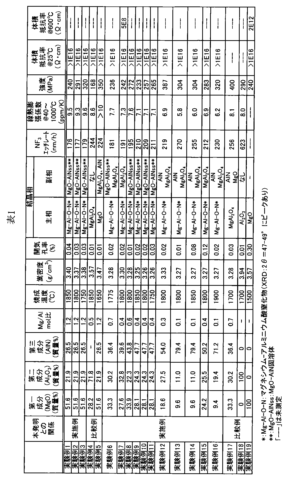
次に、上述したセラミックス材料を利用した第1構造体と第2構造体とを積層焼結した積層体について説明する(実験例20~26)。なお、実験例20~24が本発明の実施例に相当し、実験例25,26が比較例に相当する。
[実験例20、21]
実験例4,6~12のセラミックス材料は、40~1000℃の平均線熱膨張係数が7~9ppm/Kであった。実験例20,21では、表2に示すように、実験例10のセラミックス材料を第1構造体とすると共に、窒化アルミニウムを第2構造体とし、第1及び第2構造体を積層し直径50mmに成形した試料にて積層焼結を行った。この窒化アルミニウムには酸化イットリウムを焼結助剤として外配で5質量%添加したもの(つまりAlN100質量部に対してY2O35質量部の割合で添加したもの、AlN[1]という)、または50質量%添加したもの(つまりAlN100質量部に対してY2O350質量部の割合で添加したもの、AlN[2]という)を用いた。窒化アルミニウム、酸化イットリウム原料は、それぞれ純度99.9質量%以上、平均粒径1μm以下の市販品を使用した。ここで、AlN原料については1質量%程度の酸素の含有は不可避であるため、酸素を不純物元素から除いた純度である。また、40~1000℃の平均線熱膨張係数は、AlN[1]が5.7ppm/K、AlN[2]が6.2ppm/Kであることから、第1構造体と第2構造体との間には熱膨張差が生じる。このため、第1構造体と第2構造体との間に、AlN[1]あるいはAlN[2]と実験例10の原料とを混合した中間層を設けた。この中間層により、熱膨張差を緩和することができる。中間層は、AlN[1]を用いた実験例20では、質量比25:75、50:50、75:25で混合した3層とし、AlN[2]を用いた実験例21では質量比40:60、60:40で混合した2層とした。以下、調合、成形、焼成の各工程について詳説する。
・調合
第1構造体の原料は、上記の実験例10と同様の手法で作製した調合粉末を用いた。第2構造体の原料は、窒化アルミニウムを主相とし、以下のように調合した。第2構造体のAlN[1]では、まず、窒化アルミニウム粉末、酸化イットリウム粉末を100質量%、5.0質量%の割合で秤量し、イソプロピルアルコールを溶媒とし、ナイロン製のポット、ナイロン製玉石を用いて4時間湿式混合した。混合後スラリーを取り出し、窒素気流中110℃で乾燥した。その後、30メッシュの篩に通し、調合粉末とした。さらに、得られた調合粉末を450℃で5時間以上、大気雰囲気中で熱処理し、湿式混合中に混入したカーボン成分を焼失除去した。AlN[1]を用いた積層体の中間層は、以下のように調合した。まず、実験例10の調合粉末と上記の窒化アルミニウムの調合粉末とを質量比75:25(中間層1)、50:50(中間層2)、25:75(中間層3)の割合で秤量し、イソプロピルアルコールを溶媒とし、ナイロン製のポット、ナイロン製玉石を用いて4時間湿式混合した。混合後スラリーを取り出し、窒素気流中110℃で乾燥した。その後30メッシュの篩に通し、調合粉末とした。第2構造体のAlN[2]では、窒化アルミニウム粉末、酸化イットリウム粉末を100質量%、50質量%の割合で秤量した他はAlN[1]と同様の方法で調合した。また、AlN[2]を用いた積層体の中間層は、実験例10の調合粉末と上記の窒化アルミニウムの調合粉末を質量比60:40(中間層1)、40:60(中間層2)の割合で秤量した他はAlN[1]の場合と同様の方法で調合した。
・成形
最初に第2構造体の原料である窒化アルミニウム調合粉末を直径50mmの金型内に充填し、200kgf/cm2の圧力で一軸加圧成形した。窒化アルミニウム成形体は型抜きせず、その上部に窒化アルミニウム比が多い順に中間層の調合粉末を充填し、200kgf/cm2の圧力で充填毎に一軸加圧成形した。最後に第1構造体の原料である実験例10の調合粉末を充填し、200kgf/cm2にて加圧成形を行った。AlN[1]を用いた積層体については、第2構造体の窒化アルミニウム層が10mm、中間層が各1mm×3層、第1構造体の実験例10の層が10mmからなる計23mmの円盤状成形体とした。また、AlN[2]を用いた積層体については、第2構造体の窒化アルミニウム層が10mm、中間層が各1mm×2層、第1構造体の実験例10の層が10mmからなる計22mmの円盤状成形体とし、これら積層した円盤状成形体を焼成用黒鉛モールドに収納した。
・焼成
焼成用黒鉛モールドに収納した円盤状成形体をホットプレス焼成することにより、一体焼成したセラミックス材料を得た。ホットプレス焼成では、プレス圧力を200kgf/cm2とし、焼成温度1800℃で焼成し、焼成終了までAr雰囲気とした。焼成温度での保持時間は4時間とした。なお、実験例20、21については焼成温度1750℃での焼成も実施した(実験例20−1,21−1)。
上述の製造方法で得られた焼結体は、AlN[1]を用いた積層体(実験例20,20−1)、AlN[2]を用いた積層体(実験例21、21−1)と共に、上部が高耐食なマグネシウム−アルミニウム酸窒化物、焼結体の下部が高熱伝導な窒化アルミニウムを主とする焼結体で構成され、その中間に中間層が配置されていた。中間層は、第1構造体から第2構造体に近づくにつれてAlNの含有量が高くなるように傾斜させたものである。これらの焼結体には、各層間のクラック、ヒビ等はなかった。これは、第1構造体と第2構造体との間に中間層を有することで焼成中の熱応力が回避されたと考えられた。また、基材である窒化アルミニウムの熱膨張率を制御することで、基材とマグネシウム−アルミニウム酸窒化物間に生じる熱応力が小さくなり、中間層を薄くすることができた。このような焼結体は、例えば、静電チャックやサセプター、ヒーター、プレート、内壁材、監視窓、マイクロ波導入窓、マイクロ波結合用アンテナなどの半導体製造装置用部材に好適に用いられると推察された。
[実験例22~24]
実験例22では、表2に示すように、実験例6のセラミックス材料を第1構造体、酸化アルミニウムを第2構造体とし、中間層なしでN2雰囲気で積層焼結したこと以外は、実験例20と同様にして積層体を得た。実験例23では、表2に示すように、実験例6のセラミックス材料を第1構造体、酸化イットリウムを第2構造体とし、中間層なしでN2雰囲気で積層焼結したこと以外は、実験例20と同様にして積層体を得た。実験例24では、表2に示すように、実験例13のセラミックス材料を第1構造体、窒化アルミニウム(AlN[1])を第2構造体とし、中間層なしでN2雰囲気で積層焼結したこと以外は、実験例20と同様にして積層体を得た。実験例22~24のいずれにおいても、層間にクラックやヒビ等はみられなかった。また、実験例22~24では、いずれも第1構造体と第2構造体との線熱膨張係数差が0.3ppm/K以下と小さかったため、中間層なしでクラックやヒビ等の発生を防止することができた。これらの積層体も、実験例20,21と同様、静電チャックやサセプター、ヒーター、プレート、内壁材、監視窓、マイクロ波導入窓、マイクロ波結合用アンテナなどの半導体製造装置用部材に好適に用いられると推察された。なお、実験例22~24においても、実験例20,20−1,21、21−1のように中間層を設けても構わない。
[実験例25,26]
実験例25では、表2に示すように、アルミナを第1構造体、窒化アルミニウム(AlN[1])を第2構造体とし、N2雰囲気で積層焼結したこと以外は実験例20と同様にして積層体を得た。実験例26では、表2に示すように、スピネルを第1構造体、窒化アルミニウム(AlN[1])を第2構造体とし、N2雰囲気で積層焼結したこと以外は実験例20と同様にして積層体を得た。実験例25,26のいずれにおいても、層間にクラックが発生した。これは、第1構造体と第2構造体との線熱膨張係数差が大き過ぎ、その結果、中間層を設けたにもかかわらず、熱膨張差によるクラックを防止しきれなかったと考えられる。
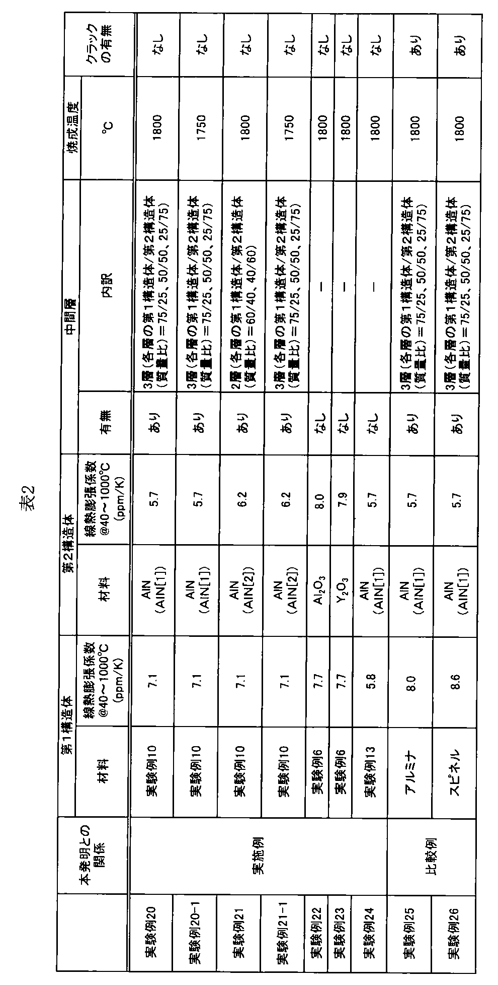
本発明に係るセラミックスヒーターの製造方法について、第5図~第9図を参照しつつ説明する。
表3に示すように、図5、図6、図7または図9に示すような加熱装置をそれぞれ製造する。
まず、実験No.1−C1、C2、C3、C4、C5、2−C1、C2、C3、C4、C5においては、リング状部を本発明のセラミックスによって形成し、サセプター部を窒化アルミニウムによって形成する。具体的には以下のプロセスによる。
(イ) リング状部の材料調整を行う。リング状部を構成する材料について、具体的には、MgO原料、Al2O3原料及びAlN原料を秤量し、イソプロピルアルコールを溶媒とし、ナイロン製のポット、直径5mmのアルミナ玉石を用いて4時間湿式混合した。混合方法としては、例えば、トロンメルと呼ばれる容器そのものが回転する大型のボールミル装置を用いて行う。混合後スラリーを取り出し、窒素気流中110℃で乾燥した。その後30メッシュの篩に通し、調合粉末とした。なお、この調合粉末のMg/Alのモル比は1.2である。
一方、サセプター部については、具体的には、窒化アルミニウムセラミックス粉末を成形用バインダと混合する。トロンメルによる混合の時間は、例えば30分程度である。その後、スプレードライヤー(SD)などの造粒装置により、造粒を行い、造粒粉を得る。
(ロ) 次に、得られたサセプター部用の造粒粉を、機械プレスによって一軸加圧下で成形し、更にリング状部用の調合粉末を所定の箇所に加え、再度機械プレスによって一軸加圧下で成形し、予備的な成形体を製造する。そして、この予備的な成形体内部に発熱体及び電流導入端子部を載置し、再び機械プレスによる成形を行う。
(ハ) 上記のようにして作られた成形体をホットプレス方式などの焼成炉に入れ、一体焼成を行う。ホットプレスは、カーボン治具内に原料粉末や成形体を充填、あるいは挿入し、30~50MPaの一軸加圧下で焼成するもので、通常の常圧焼結では、緻密化が困難なセラミックス材料の焼成に適する。このときの焼成条件は、焼成温度1600℃~2000℃、圧力100~300kg/cm2、焼成時間2~5時間である。
(ニ) また、サセプターの背面側にシャフトを設ける。シャフト部分は、プレートとは別途に製造される。まず、シャフトの材料調整を行う。具体的には、プレートのサセプター部を構成する窒化アルミニウムセラミックスの材料調整と同じくして調合粉末を得る。得られた調合粉末を冷間等方圧プレス(冷間静水圧プレス:Cold Isostatic Pressing,CIP)などの焼成炉に入れ、焼成を行い、成形体を製造する。CIPとは、金型成形法により得られる一軸成形体に等方圧の成形処理を施す方法であり、成形体密度の向上とむらをなくすことができる。金型成形せずに、直接、ゴム型に原料粉末を充填しCIP処理を行い、成形体を得ることも可能である。こうして得られたシャフトの成形体を常圧焼成炉などにより焼成を行う。このときの焼成条件は、焼成温度1600℃~2000℃、圧力1~30kg/cm2、焼成時間1~5時間である。そして、シャフトの外周やラッピングの加工を行う。上記の手順で得られたプレートとシャフトは、ダイレクトボンド法により、焼成炉内で接合される。このときの焼成条件は、焼成温度1400℃~2000℃、圧力100~300kg/cm2、焼成時間2~5時間である。
(ホ) リング状部材の配置範囲は、表3に示すように種々変更した。ただし、リング状部材の設置範囲を、サセプターの中心からの距離(R)として、種々変更した。
ただし、実験No.1−C1、C2、C5では、図5に示すように、サセプター部の外周エッジまでリング状部が延びている。実験No.1−C3、C4では、図6に示すように、サセプター部の外周にリング状突起2cが形成されている。実験No.2−C3、C4では、図7に示すように、リング状部の外周にリング状突起6aが形成されており、かつサセプター部の外周にリング状突起2cが形成されている。実験No.2−C1、C2、C5では、図7に示すように、リング状部の外周にリング状突起6aが形成されているが、しかしサセプター部の外周エッジまでリング状部が延びており、サセプター部の外周にリング状突起2cが形成されていない。
[実験No.1−A、2−A]
実験No.1−Aでは、図9に示すようなサセプターを製造する。実験No.2−Aでは、図7に示すようなサセプターを製造するが、しかしサセプター部の外周エッジまでリング状部が延びており、サセプター部の外周にリング状突起2cが形成されていない。サセプターの材質は窒化アルミニウムのみとし、実験No.1−C、2−Cのように製造する。
[実験No.1−B、2−B]
実験No.1−Bでは、図9に示すようなサセプターを製造する。実験No.2−Bでは、図7に示すようなサセプターを製造するが、しかしサセプター部の外周エッジまでリング状部が延びており、サセプター部の外周にリング状突起2cが形成されていない。サセプターの材質は、MgAlONを主相とする前記セラミックス材料のみとし、実験No.1−C、2−Cのように製造する。
[試験条件]
・耐食試験:ICP:800W,バイアス:450W,導入ガス:NF3/O2/Ar=75/35/100sccm,0.05Torr,暴露時間:100hrs.,試料温度:600℃
・評価特性:上記の耐食試験前後における、ウエハ上温度均一性、パーティクル量、表面粗度
・ウエハ外周部成膜レンジ
各例のセラミックヒータをCVD内に設置し、シリコンウエハをセラミックヒータ上に設置し、550℃に加熱し、絶縁膜のCVD成膜を行った。得られた成膜後のウエハ外周部における膜の厚みを測定し最大値と最小値との差(レンジ)を算出した。なお、ヒーターの各温度への加熱は、セラミックスプレートの背面に取り付けられた図示しない熱電対による温度制御により行った。外周部成膜レンジとは具体的には、R140~R147mmの範囲での成膜厚みの最大1最小の差で定義される。
下表の各実験例において用いたMg−Al−O−Nを主相とする前記材料は、上述の実施例(表1)における実験例12の組成である。

実験No.1−A、2−Aでは、サセプターが窒化アルミニウムからなっているが、耐食試験前後ともに成膜レンジが大きい。
実験No.1−B、2−Bでは、サセプターが、MgAlONを主相とする前記セラミックス材料のみからなっているが、耐蝕性が高く、耐食試験後にも成膜レンジが劣化しない。しかし、耐食試験前の成膜レンジは、実験No.1−C、2−Cよりも劣っている。
これらの作用効果は、半導体処理装置分野において画期的であり、産業上多大な利用を期待できることが明らかである。
本発明の特定の実施形態を説明してきたけれども、本発明はこれら特定の実施形態に限定されるものではなく、請求の範囲の範囲から離れることなく、種々の変更や改変を行いながら実施できる。
Claims (20)
- 半導体を加熱する加熱面を有するサセプター部と、前記加熱面の外側に設けられているリング状部とを備えている加熱装置であって、
前記リング状部が、マグネシウム、アルミニウム、酸素及び窒素を主成分とするセラミックス材料からなり、このセラミックス材料が、CuKα線を用いたときのXRDピークが少なくとも2θ=47~50°に現れるマグネシウム−アルミニウム酸窒化物相を主相とすることを特徴とする、加熱装置。 - 前記サセプター部が、前記リング状部の外周エッジを包囲する外周側突起を備えていることを特徴とする、請求項1記載の加熱装置。
- 前記リング状部が、前記半導体の外周部を載置する載置部を備えていることを特徴とする、請求項1または2記載の加熱装置。
- 前記リング状部が、前記載置部の外側に設けられており、前記半導体を包囲する非載置部を備えていることを特徴とする、請求項3記載の加熱装置。
- 前記非載置部が、前記半導体の外周エッジを包囲するリング状突起からなることを特徴とする、請求項4記載の加熱装置。
- 前記サセプター部と前記リング状部とが一体焼結されていることを特徴とする、請求項1~5のいずれか一つの請求項に記載の加熱装置。
- 前記サセプター部と前記リング状部との間に設けられる中間層を備えていることを特徴とする、請求項1~6のいずれか一つの請求項に記載の加熱装置。
- 前記サセプター部の内部に埋設されている発熱体、および前記サセプター部の内部に埋設されている高周波発生電極を備えていることを特徴とする、請求項1~7のいずれか一つの請求項に記載の加熱装置。
- 前記サセプター部の背面に接合されている支持部を備えていることを特徴とする、請求項1~8のいずれか一つの請求項に記載の加熱装置。
- 前記2θは47~49°である、請求項1~9のいずれか一つの請求項に記載の加熱装置。
- 前記セラミックス材料が、酸化マグネシウムに窒化アルミニウムが固溶したMgO−AlN固溶体の結晶相を副相とする、請求項1~10のいずれか一つの請求項に記載の加熱装置。
- 前記MgO−AlN固溶体は、CuKα線を用いたときの(200)面及び(220)面のXRDピークが酸化マグネシウムの立方晶のピークと窒化アルミニウムの立方晶のピークとの間である2θ=42.9~44.8°,62.3~65.2°に現れる、請求項11記載の加熱装置。
- 前記MgO−AlN固溶体は、CuKα線を用いたときの(111)面のXRDピークが酸化マグネシウムの立方晶のピークと窒化アルミニウムの立方晶のピークとの間である2θ=36.9~39°に現れる、請求項12記載の加熱装置。
- 前記サセプター部を構成する材質が、窒化アルミニウム、酸化イットリウムまたは酸化アルミニウムを主相とするセラミックスからなることを特徴とする、請求項1~13のいずれか一つの請求項に記載の加熱装置。
- 半導体を加熱する加熱面を有するサセプター上に設置されるリング状部であって、
前記リング状部が、マグネシウム、アルミニウム、酸素及び窒素を主成分とするセラミックス材料からなり、このセラミックス材料が、CuKα線を用いたときのXRDピークが少なくとも2θ=47~50°に現れるマグネシウム−アルミニウム酸窒化物相を主相とすることを特徴とする、リング状部。 - 前記半導体の外周エッジを包囲するリング状突起を備えていることを特徴とする、請求項15記載のリング状部。
- 前記2θは47~49°である、請求項15または16記載のリング状部。
- 前記セラミックス材料が、酸化マグネシウムに窒化アルミニウムが固溶したMgO−AlN固溶体の結晶相を副相とする、請求項15~17のいずれか一つの請求項に記載のリング状部。
- 前記MgO−AlN固溶体は、CuKα線を用いたときの(200)面及び(220)面のXRDピークが酸化マグネシウムの立方晶のピークと窒化アルミニウムの立方晶のピークとの間である2θ=42.9~44.8°,62.3~65.2°に現れる、請求項18記載のリング状部。
- 前記MgO−AlN固溶体は、CuKα線を用いたときの(111)面のXRDピークが酸化マグネシウムの立方晶のピークと窒化アルミニウムの立方晶のピークとの間である2θ=36.9~39°に現れる、請求項19記載のリング状部。
Priority Applications (4)
| Application Number | Priority Date | Filing Date | Title |
|---|---|---|---|
| KR1020137008953A KR101597882B1 (ko) | 2010-10-25 | 2011-10-11 | 가열 장치 |
| CN201180051354.3A CN103201236B (zh) | 2010-10-25 | 2011-10-11 | 加热装置 |
| JP2012540771A JP5680663B2 (ja) | 2010-10-25 | 2011-10-11 | 加熱装置 |
| US13/863,803 US9287144B2 (en) | 2010-10-25 | 2013-04-16 | Heating device |
Applications Claiming Priority (6)
| Application Number | Priority Date | Filing Date | Title |
|---|---|---|---|
| JP2010-239000 | 2010-10-25 | ||
| JP2010239000 | 2010-10-25 | ||
| JP2011135312 | 2011-06-17 | ||
| JP2011-135312 | 2011-06-17 | ||
| JPPCT/JP2011/069479 | 2011-08-29 | ||
| PCT/JP2011/069479 WO2012056807A1 (ja) | 2010-10-25 | 2011-08-29 | セラミックス材料、積層体、半導体製造装置用部材及びスパッタリングターゲット部材 |
Related Child Applications (1)
| Application Number | Title | Priority Date | Filing Date |
|---|---|---|---|
| US13/863,803 Continuation US9287144B2 (en) | 2010-10-25 | 2013-04-16 | Heating device |
Publications (1)
| Publication Number | Publication Date |
|---|---|
| WO2012056914A1 true WO2012056914A1 (ja) | 2012-05-03 |
Family
ID=45993537
Family Applications (6)
| Application Number | Title | Priority Date | Filing Date |
|---|---|---|---|
| PCT/JP2011/069479 Ceased WO2012056807A1 (ja) | 2010-10-25 | 2011-08-29 | セラミックス材料、積層体、半導体製造装置用部材及びスパッタリングターゲット部材 |
| PCT/JP2011/073329 Ceased WO2012056875A1 (ja) | 2010-10-25 | 2011-10-11 | セラミックス材料、積層体、半導体製造装置用部材及びスパッタリングターゲット部材 |
| PCT/JP2011/073770 Ceased WO2012056917A1 (ja) | 2010-10-25 | 2011-10-11 | 加熱装置 |
| PCT/JP2011/073768 Ceased WO2012056915A1 (ja) | 2010-10-25 | 2011-10-11 | 静電チャック |
| PCT/JP2011/073769 Ceased WO2012056916A1 (ja) | 2010-10-25 | 2011-10-11 | 加熱装置 |
| PCT/JP2011/073767 Ceased WO2012056914A1 (ja) | 2010-10-25 | 2011-10-11 | 加熱装置 |
Family Applications Before (5)
| Application Number | Title | Priority Date | Filing Date |
|---|---|---|---|
| PCT/JP2011/069479 Ceased WO2012056807A1 (ja) | 2010-10-25 | 2011-08-29 | セラミックス材料、積層体、半導体製造装置用部材及びスパッタリングターゲット部材 |
| PCT/JP2011/073329 Ceased WO2012056875A1 (ja) | 2010-10-25 | 2011-10-11 | セラミックス材料、積層体、半導体製造装置用部材及びスパッタリングターゲット部材 |
| PCT/JP2011/073770 Ceased WO2012056917A1 (ja) | 2010-10-25 | 2011-10-11 | 加熱装置 |
| PCT/JP2011/073768 Ceased WO2012056915A1 (ja) | 2010-10-25 | 2011-10-11 | 静電チャック |
| PCT/JP2011/073769 Ceased WO2012056916A1 (ja) | 2010-10-25 | 2011-10-11 | 加熱装置 |
Country Status (6)
| Country | Link |
|---|---|
| US (5) | US8597776B2 (ja) |
| JP (5) | JP5680665B2 (ja) |
| KR (6) | KR101597882B1 (ja) |
| CN (6) | CN103201236B (ja) |
| TW (4) | TWI530474B (ja) |
| WO (6) | WO2012056807A1 (ja) |
Cited By (2)
| Publication number | Priority date | Publication date | Assignee | Title |
|---|---|---|---|---|
| JP2019167288A (ja) * | 2018-03-23 | 2019-10-03 | 日本碍子株式会社 | 複合焼結体、半導体製造装置部材および複合焼結体の製造方法 |
| KR20190114373A (ko) * | 2018-03-30 | 2019-10-10 | (주)티티에스 | 유리 기판 지지용 서셉터 |
Families Citing this family (53)
| Publication number | Priority date | Publication date | Assignee | Title |
|---|---|---|---|---|
| CN102918629A (zh) * | 2010-05-28 | 2013-02-06 | 艾克塞利斯科技公司 | 用于静电夹具的匹配的热膨胀系数 |
| WO2012056808A1 (ja) * | 2010-10-25 | 2012-05-03 | 日本碍子株式会社 | セラミックス材料、半導体製造装置用部材、スパッタリングターゲット部材及びセラミックス材料の製造方法 |
| WO2013054806A1 (ja) * | 2011-10-11 | 2013-04-18 | 日本碍子株式会社 | セラミックス部材、半導体製造装置用部材及びセラミックス部材の製造方法 |
| JP5934069B2 (ja) | 2012-09-14 | 2016-06-15 | 日本碍子株式会社 | 積層構造体、半導体製造装置用部材及び積層構造体の製造方法 |
| KR102142037B1 (ko) * | 2012-11-07 | 2020-08-06 | 엔지케이 인슐레이터 엘티디 | 세라믹스 재료 및 스퍼터링 타겟 부재 |
| ES2537284T3 (es) * | 2012-11-13 | 2015-06-05 | Refractory Intellectual Property Gmbh & Co. Kg | Procedimiento para fabricar un material refractario a base de magnesia o magnesia-espinela, así como un material refractario a base de magnesia o magnesia-espinela |
| EP2738815B1 (en) | 2012-11-30 | 2016-02-10 | Samsung Electronics Co., Ltd | Semiconductor materials, transistors including the same, and electronic devices including transistors |
| JP6450163B2 (ja) * | 2013-12-06 | 2019-01-09 | 日本碍子株式会社 | 溶射膜、半導体製造装置用部材、溶射用原料及び溶射膜製造方法 |
| JP6349100B2 (ja) * | 2014-02-14 | 2018-06-27 | 株式会社アテクト | アルミナ焼結体及びその製造方法 |
| US10410897B2 (en) * | 2014-06-23 | 2019-09-10 | Ngk Spark Plug Co., Ltd. | Electrostatic chuck |
| KR102059092B1 (ko) * | 2014-06-30 | 2019-12-24 | 엔지케이 인슐레이터 엘티디 | MgO계 세라믹스막, 반도체 제조 장치용 부재 및 MgO계 세라믹스막의 제법 |
| CN104744045B (zh) * | 2015-03-25 | 2017-10-24 | 武汉理工大学 | 一种直接凝固注模成型制备MgAlON透明陶瓷素坯的方法 |
| KR102348108B1 (ko) * | 2015-10-05 | 2022-01-10 | 주식회사 미코세라믹스 | 온도 편차 특성이 개선된 기판 가열 장치 |
| US10464849B2 (en) * | 2015-12-08 | 2019-11-05 | Edward J. A. Pope | Fast-densified ceramic matrix composite and fabrication method |
| JP6560150B2 (ja) * | 2016-03-28 | 2019-08-14 | 日本碍子株式会社 | ウエハ載置装置 |
| US10340171B2 (en) | 2016-05-18 | 2019-07-02 | Lam Research Corporation | Permanent secondary erosion containment for electrostatic chuck bonds |
| KR20170138052A (ko) * | 2016-06-06 | 2017-12-14 | 어플라이드 머티어리얼스, 인코포레이티드 | 최적의 박막 증착 또는 에칭 프로세스들을 위한 특성들을 갖는 정전 척 |
| US11069553B2 (en) * | 2016-07-07 | 2021-07-20 | Lam Research Corporation | Electrostatic chuck with features for preventing electrical arcing and light-up and improving process uniformity |
| US10910195B2 (en) | 2017-01-05 | 2021-02-02 | Lam Research Corporation | Substrate support with improved process uniformity |
| TWI771375B (zh) * | 2017-02-24 | 2022-07-21 | 美商康寧公司 | 高寬高比玻璃晶圓 |
| US11457513B2 (en) | 2017-04-13 | 2022-09-27 | Bradford White Corporation | Ceramic heating element |
| KR102298654B1 (ko) * | 2017-04-19 | 2021-09-07 | 주식회사 미코세라믹스 | 내구성이 개선된 세라믹 히터 |
| US11685695B2 (en) | 2017-05-30 | 2023-06-27 | Kyocera Corporation | Aluminum nitride-based sintered compact and semiconductor holding device |
| US11289355B2 (en) | 2017-06-02 | 2022-03-29 | Lam Research Corporation | Electrostatic chuck for use in semiconductor processing |
| CN109216189B (zh) * | 2017-06-30 | 2021-02-26 | 台湾积体电路制造股份有限公司 | 加热装置 |
| JP6967944B2 (ja) * | 2017-11-17 | 2021-11-17 | 東京エレクトロン株式会社 | プラズマ処理装置 |
| KR102188366B1 (ko) * | 2017-11-21 | 2020-12-08 | 와틀로 일렉트릭 매뉴팩츄어링 컴파니 | 세라믹 받침대에서 사용하기 위한 이중 목적 비아 |
| JP7033441B2 (ja) * | 2017-12-01 | 2022-03-10 | 東京エレクトロン株式会社 | プラズマ処理装置 |
| JP7055811B2 (ja) * | 2018-03-26 | 2022-04-18 | 日本碍子株式会社 | ウエハ支持台 |
| KR102519299B1 (ko) * | 2018-03-27 | 2023-04-06 | 엔지케이 인슐레이터 엘티디 | 질화알루미늄판 |
| CN109053192B (zh) * | 2018-09-30 | 2020-01-21 | 湖南工学院 | 一种MgAlON透明陶瓷粉体的制备方法 |
| CN110282984A (zh) * | 2019-06-25 | 2019-09-27 | 兰品军 | 测试用可变组分的陶瓷旋转靶材及其制备方法 |
| KR102472864B1 (ko) * | 2019-08-06 | 2022-12-02 | 주식회사 미코세라믹스 | 정전척 히터 및 그 제조방법 |
| JP7202322B2 (ja) * | 2020-02-03 | 2023-01-11 | 日本碍子株式会社 | セラミックヒータ |
| JP7412242B2 (ja) * | 2020-03-27 | 2024-01-12 | 日本碍子株式会社 | 積層構造体および半導体製造装置部材 |
| JP6738505B1 (ja) * | 2020-05-28 | 2020-08-12 | 黒崎播磨株式会社 | 静電チャック用誘電体 |
| JP7663332B2 (ja) * | 2020-09-29 | 2025-04-16 | 日本特殊陶業株式会社 | 基板保持部材、およびその製造方法 |
| KR20220101566A (ko) * | 2021-01-11 | 2022-07-19 | 에이에스엠 아이피 홀딩 비.브이. | 정전기 척 |
| JP7836151B2 (ja) * | 2021-03-31 | 2026-03-26 | 日本特殊陶業株式会社 | 支持部材、基板保持部材、およびその製造方法 |
| JP7859748B2 (ja) | 2021-08-23 | 2026-05-15 | Ngk株式会社 | AlN接合体 |
| KR102583016B1 (ko) * | 2021-11-18 | 2023-09-25 | 김성환 | MgO계 정전척 및 그 제조방법 |
| JP7689634B2 (ja) * | 2021-11-19 | 2025-06-06 | ケーエスエム・コンポーネント・カンパニー・リミテッド | 半導体製造装置用セラミックヒーター |
| JP7628979B2 (ja) | 2022-03-17 | 2025-02-12 | 日本碍子株式会社 | 高抵抗・高耐食セラミックス材料及びウエハ載置台 |
| US12512357B2 (en) * | 2022-04-01 | 2025-12-30 | Applied Materials, Inc. | Ceramic engineering by grading materials |
| JP7721224B2 (ja) * | 2022-05-18 | 2025-08-12 | 株式会社フェローテックマテリアルテクノロジーズ | ウエハ支持体 |
| KR102679660B1 (ko) * | 2022-07-28 | 2024-06-28 | 주식회사 그린리소스 | 고온 히터용 코팅재의 제조 방법 |
| KR102681418B1 (ko) * | 2023-10-25 | 2024-07-05 | 주식회사 케이에스엠컴포넌트 | 세라믹 서셉터 및 이의 제조방법 |
| US12482588B2 (en) * | 2024-01-09 | 2025-11-25 | Western Digital Technologies, Inc. | Nitrogen doped oxides for lower bandgap |
| KR102760863B1 (ko) | 2024-04-17 | 2025-02-04 | 주식회사 케이에스엠컴포넌트 | 하이브리드 코팅을 포함하는 세라믹 서셉터 |
| KR102902290B1 (ko) * | 2024-05-27 | 2025-12-22 | 엔지케이 인슐레이터 엘티디 | 반도체 제조 장치용 부재 |
| WO2025248844A1 (ja) * | 2024-05-27 | 2025-12-04 | 日本碍子株式会社 | 半導体製造装置用部材 |
| CN118930284A (zh) * | 2024-06-30 | 2024-11-12 | 君原电子科技(海宁)有限公司 | 一种提高静电卡盘陶瓷板烧结平整度的方法 |
| WO2026088752A1 (ja) * | 2024-10-22 | 2026-04-30 | 日本碍子株式会社 | セラミックヒータ |
Citations (10)
| Publication number | Priority date | Publication date | Assignee | Title |
|---|---|---|---|---|
| JPS6228917A (ja) * | 1985-07-29 | 1987-02-06 | Hitachi Ltd | 簿膜磁気ヘツド用スライダおよびその製造方法 |
| JPH04304359A (ja) * | 1991-01-03 | 1992-10-27 | Pechiney Electrometall | 低融点金属の直接窒化処理方法 |
| JPH05319937A (ja) * | 1992-05-21 | 1993-12-03 | Toshiba Corp | 傾斜機能材料 |
| JPH0637207A (ja) * | 1992-07-15 | 1994-02-10 | Ibiden Co Ltd | GaAs半導体素子用基板及びその製造方法 |
| JPH09219369A (ja) * | 1996-02-13 | 1997-08-19 | Toshiba Corp | 半導体装置の製造装置および製造方法 |
| JP2000044345A (ja) * | 1998-07-24 | 2000-02-15 | Ngk Insulators Ltd | 窒化アルミニウム質焼結体、耐蝕性部材、金属埋設品および半導体保持装置 |
| JP2005203456A (ja) * | 2004-01-14 | 2005-07-28 | Ngk Insulators Ltd | 加熱装置 |
| JP2007084367A (ja) * | 2005-09-21 | 2007-04-05 | Matsushita Electric Works Ltd | 高熱伝導性セラミックス焼結体の製造方法及び高熱伝導性セラミックス焼結体 |
| JP2007300079A (ja) * | 2006-05-04 | 2007-11-15 | Hitachi Ltd | 磁気メモリ素子 |
| JP2008115065A (ja) * | 2006-11-02 | 2008-05-22 | Okayama Ceramics Gijutsu Shinko Zaidan | 使用済みマグネシア質、スピネル質およびアルミナ質耐火物のリサイクル方法 |
Family Cites Families (29)
| Publication number | Priority date | Publication date | Assignee | Title |
|---|---|---|---|---|
| US3531245A (en) * | 1968-04-01 | 1970-09-29 | Du Pont | Magnesium-aluminum nitrides |
| US5231062A (en) * | 1990-08-09 | 1993-07-27 | Minnesota Mining And Manufacturing Company | Transparent aluminum oxynitride-based ceramic article |
| FR2675158B1 (fr) | 1991-04-15 | 1994-05-06 | Pechiney Electrometallurgie | Produits abrasifs et/ou refractaires a base d'oxynitrures, fondus et solidifies. |
| US5457075A (en) * | 1993-05-11 | 1995-10-10 | Hitachi Metals, Ltd. | Sintered ceramic composite and molten metal contact member produced therefrom |
| JP2783980B2 (ja) | 1994-09-01 | 1998-08-06 | 日本碍子株式会社 | 接合体およびその製造方法 |
| US5886863A (en) * | 1995-05-09 | 1999-03-23 | Kyocera Corporation | Wafer support member |
| JP3559426B2 (ja) | 1997-05-30 | 2004-09-02 | 京セラ株式会社 | 耐食性部材 |
| US6447937B1 (en) | 1997-02-26 | 2002-09-10 | Kyocera Corporation | Ceramic materials resistant to halogen plasma and components using the same |
| JP4447750B2 (ja) * | 1999-09-30 | 2010-04-07 | 日本碍子株式会社 | 窒化アルミニウム焼結体および半導体製造用部材 |
| US6328807B1 (en) * | 1999-12-14 | 2001-12-11 | Corning Incorporated | Chuck heater for improved planar deposition process |
| JP2001257144A (ja) * | 2000-03-09 | 2001-09-21 | Tokyo Electron Ltd | 基板の加熱処理装置 |
| JP3851489B2 (ja) | 2000-04-27 | 2006-11-29 | 日本発条株式会社 | 静電チャック |
| AU2001296006A1 (en) | 2000-10-23 | 2002-05-06 | Akedo, Jun | Composite structure and method and apparatus for manufacture thereof |
| JP2003124541A (ja) * | 2001-10-12 | 2003-04-25 | Nec Corp | 交換結合膜、磁気抵抗効果素子、磁気ヘッド及び磁気ランダムアクセスメモリ |
| JP4493264B2 (ja) * | 2001-11-26 | 2010-06-30 | 日本碍子株式会社 | 窒化アルミニウム質セラミックス、半導体製造用部材および耐蝕性部材 |
| JP4034096B2 (ja) * | 2002-03-19 | 2008-01-16 | 日本碍子株式会社 | 半導体支持装置 |
| JP3888531B2 (ja) | 2002-03-27 | 2007-03-07 | 日本碍子株式会社 | セラミックヒーター、セラミックヒーターの製造方法、および金属部材の埋設品 |
| JP4424659B2 (ja) * | 2003-02-28 | 2010-03-03 | 日本碍子株式会社 | 窒化アルミニウム質材料および半導体製造装置用部材 |
| JP2004311837A (ja) | 2003-04-09 | 2004-11-04 | Ngk Insulators Ltd | 半導体製造装置用部材とその製造方法 |
| JP4292128B2 (ja) | 2004-09-07 | 2009-07-08 | キヤノンアネルバ株式会社 | 磁気抵抗効果素子の製造方法 |
| KR100918190B1 (ko) * | 2005-04-22 | 2009-09-22 | 주식회사 코미코 | 치밀질 질화알루미늄 소결체, 그 제조 방법 및 상기소결체를 이용한 반도체 제조용 부재 |
| JP4753851B2 (ja) * | 2005-12-19 | 2011-08-24 | 日本碍子株式会社 | 窒化アルミニウム粉末、窒化アルミニウム質セラミックス焼結体、半導体製造装置用部材、窒化アルミニウム発光材料、及び窒化アルミニウム粉末の製造方法 |
| WO2008093871A1 (ja) * | 2007-02-02 | 2008-08-07 | Tokuyama Corporation | 窒化アルミニウム焼結体およびその製造方法 |
| JP2009292688A (ja) | 2008-06-06 | 2009-12-17 | Sumitomo Electric Ind Ltd | 透光性セラミックスおよびその製造方法、それを用いた光学素子、カラー液晶プロジェクター |
| JP5307671B2 (ja) * | 2008-10-23 | 2013-10-02 | 日本碍子株式会社 | 窒化アルミニウム基複合材料、その製造方法及び半導体製造装置用部材 |
| US8486221B2 (en) | 2009-02-05 | 2013-07-16 | Tokyo Electron Limited | Focus ring heating method, plasma etching apparatus, and plasma etching method |
| JP5686971B2 (ja) | 2009-02-05 | 2015-03-18 | 東京エレクトロン株式会社 | フォーカスリングの加熱方法及びプラズマエッチング装置及びプラズマエッチング方法 |
| JP5395633B2 (ja) | 2009-11-17 | 2014-01-22 | 東京エレクトロン株式会社 | 基板処理装置の基板載置台 |
| CN101723673B (zh) * | 2009-12-10 | 2013-03-20 | 洛阳理工学院 | 一种高导热AlN电子陶瓷基片的生产方法 |
-
2011
- 2011-08-29 WO PCT/JP2011/069479 patent/WO2012056807A1/ja not_active Ceased
- 2011-10-11 WO PCT/JP2011/073329 patent/WO2012056875A1/ja not_active Ceased
- 2011-10-11 KR KR1020137008953A patent/KR101597882B1/ko active Active
- 2011-10-11 CN CN201180051354.3A patent/CN103201236B/zh active Active
- 2011-10-11 CN CN201180004702.1A patent/CN102639464B/zh active Active
- 2011-10-11 JP JP2012540774A patent/JP5680665B2/ja active Active
- 2011-10-11 KR KR1020137008109A patent/KR101597881B1/ko active Active
- 2011-10-11 WO PCT/JP2011/073770 patent/WO2012056917A1/ja not_active Ceased
- 2011-10-11 CN CN201180050730.7A patent/CN103168014B/zh active Active
- 2011-10-11 TW TW100136727A patent/TWI530474B/zh active
- 2011-10-11 KR KR1020127013442A patent/KR101851806B1/ko active Active
- 2011-10-11 TW TW100136724A patent/TWI538030B/zh active
- 2011-10-11 JP JP2012540771A patent/JP5680663B2/ja active Active
- 2011-10-11 KR KR1020137007350A patent/KR101661385B1/ko active Active
- 2011-10-11 WO PCT/JP2011/073768 patent/WO2012056915A1/ja not_active Ceased
- 2011-10-11 WO PCT/JP2011/073769 patent/WO2012056916A1/ja not_active Ceased
- 2011-10-11 KR KR1020187006138A patent/KR101938123B1/ko active Active
- 2011-10-11 CN CN201610080984.8A patent/CN105679663B/zh active Active
- 2011-10-11 TW TW100136722A patent/TWI525703B/zh active
- 2011-10-11 CN CN201180051162.2A patent/CN103180266B/zh active Active
- 2011-10-11 CN CN201180051175.XA patent/CN103180267B/zh active Active
- 2011-10-11 JP JP2012540773A patent/JP5680664B2/ja active Active
- 2011-10-11 WO PCT/JP2011/073767 patent/WO2012056914A1/ja not_active Ceased
- 2011-10-11 TW TW100136717A patent/TWI552256B/zh active
- 2011-10-11 JP JP2012524039A patent/JP5680645B2/ja active Active
- 2011-10-11 KR KR1020137009043A patent/KR101679904B1/ko active Active
- 2011-10-11 JP JP2012540772A patent/JP5683601B2/ja active Active
-
2012
- 2012-05-23 US US13/478,508 patent/US8597776B2/en active Active
-
2013
- 2013-04-16 US US13/863,729 patent/US9437463B2/en active Active
- 2013-04-16 US US13/863,803 patent/US9287144B2/en active Active
- 2013-04-17 US US13/864,559 patent/US9245775B2/en active Active
- 2013-04-17 US US13/864,467 patent/US9202718B2/en active Active
Patent Citations (10)
| Publication number | Priority date | Publication date | Assignee | Title |
|---|---|---|---|---|
| JPS6228917A (ja) * | 1985-07-29 | 1987-02-06 | Hitachi Ltd | 簿膜磁気ヘツド用スライダおよびその製造方法 |
| JPH04304359A (ja) * | 1991-01-03 | 1992-10-27 | Pechiney Electrometall | 低融点金属の直接窒化処理方法 |
| JPH05319937A (ja) * | 1992-05-21 | 1993-12-03 | Toshiba Corp | 傾斜機能材料 |
| JPH0637207A (ja) * | 1992-07-15 | 1994-02-10 | Ibiden Co Ltd | GaAs半導体素子用基板及びその製造方法 |
| JPH09219369A (ja) * | 1996-02-13 | 1997-08-19 | Toshiba Corp | 半導体装置の製造装置および製造方法 |
| JP2000044345A (ja) * | 1998-07-24 | 2000-02-15 | Ngk Insulators Ltd | 窒化アルミニウム質焼結体、耐蝕性部材、金属埋設品および半導体保持装置 |
| JP2005203456A (ja) * | 2004-01-14 | 2005-07-28 | Ngk Insulators Ltd | 加熱装置 |
| JP2007084367A (ja) * | 2005-09-21 | 2007-04-05 | Matsushita Electric Works Ltd | 高熱伝導性セラミックス焼結体の製造方法及び高熱伝導性セラミックス焼結体 |
| JP2007300079A (ja) * | 2006-05-04 | 2007-11-15 | Hitachi Ltd | 磁気メモリ素子 |
| JP2008115065A (ja) * | 2006-11-02 | 2008-05-22 | Okayama Ceramics Gijutsu Shinko Zaidan | 使用済みマグネシア質、スピネル質およびアルミナ質耐火物のリサイクル方法 |
Cited By (4)
| Publication number | Priority date | Publication date | Assignee | Title |
|---|---|---|---|---|
| JP2019167288A (ja) * | 2018-03-23 | 2019-10-03 | 日本碍子株式会社 | 複合焼結体、半導体製造装置部材および複合焼結体の製造方法 |
| JP7213710B2 (ja) | 2018-03-23 | 2023-01-27 | 日本碍子株式会社 | 複合焼結体、半導体製造装置部材および複合焼結体の製造方法 |
| KR20190114373A (ko) * | 2018-03-30 | 2019-10-10 | (주)티티에스 | 유리 기판 지지용 서셉터 |
| KR102080231B1 (ko) * | 2018-03-30 | 2020-02-21 | (주)티티에스 | 유리 기판 지지용 서셉터 |
Also Published As
Similar Documents
| Publication | Publication Date | Title |
|---|---|---|
| JP5680663B2 (ja) | 加熱装置 | |
| JP5683602B2 (ja) | 静電チャック | |
| WO2026088752A1 (ja) | セラミックヒータ |
Legal Events
| Date | Code | Title | Description |
|---|---|---|---|
| 121 | Ep: the epo has been informed by wipo that ep was designated in this application |
Ref document number: 11836051 Country of ref document: EP Kind code of ref document: A1 |
|
| WWE | Wipo information: entry into national phase |
Ref document number: 2012540771 Country of ref document: JP |
|
| ENP | Entry into the national phase |
Ref document number: 20137008953 Country of ref document: KR Kind code of ref document: A |
|
| NENP | Non-entry into the national phase |
Ref country code: DE |
|
| 122 | Ep: pct application non-entry in european phase |
Ref document number: 11836051 Country of ref document: EP Kind code of ref document: A1 |