WO2012053237A1 - 耐熱合金の切削加工で優れた耐欠損性を発揮するwc基超硬合金製切削工具および表面被覆wc基超硬合金製切削工具 - Google Patents
耐熱合金の切削加工で優れた耐欠損性を発揮するwc基超硬合金製切削工具および表面被覆wc基超硬合金製切削工具 Download PDFInfo
- Publication number
- WO2012053237A1 WO2012053237A1 PCT/JP2011/057936 JP2011057936W WO2012053237A1 WO 2012053237 A1 WO2012053237 A1 WO 2012053237A1 JP 2011057936 W JP2011057936 W JP 2011057936W WO 2012053237 A1 WO2012053237 A1 WO 2012053237A1
- Authority
- WO
- WIPO (PCT)
- Prior art keywords
- cemented carbide
- based cemented
- cutting tool
- particles
- content
- Prior art date
- Legal status (The legal status is an assumption and is not a legal conclusion. Google has not performed a legal analysis and makes no representation as to the accuracy of the status listed.)
- Ceased
Links
Images


Classifications
-
- C—CHEMISTRY; METALLURGY
- C22—METALLURGY; FERROUS OR NON-FERROUS ALLOYS; TREATMENT OF ALLOYS OR NON-FERROUS METALS
- C22C—ALLOYS
- C22C29/00—Alloys based on carbides, oxides, nitrides, borides, or silicides, e.g. cermets, or other metal compounds, e.g. oxynitrides, sulfides
- C22C29/02—Alloys based on carbides, oxides, nitrides, borides, or silicides, e.g. cermets, or other metal compounds, e.g. oxynitrides, sulfides based on carbides or carbonitrides
- C22C29/06—Alloys based on carbides, oxides, nitrides, borides, or silicides, e.g. cermets, or other metal compounds, e.g. oxynitrides, sulfides based on carbides or carbonitrides based on carbides, but not containing other metal compounds
- C22C29/08—Alloys based on carbides, oxides, nitrides, borides, or silicides, e.g. cermets, or other metal compounds, e.g. oxynitrides, sulfides based on carbides or carbonitrides based on carbides, but not containing other metal compounds based on tungsten carbide
-
- B—PERFORMING OPERATIONS; TRANSPORTING
- B22—CASTING; POWDER METALLURGY
- B22F—WORKING METALLIC POWDER; MANUFACTURE OF ARTICLES FROM METALLIC POWDER; MAKING METALLIC POWDER; APPARATUS OR DEVICES SPECIALLY ADAPTED FOR METALLIC POWDER
- B22F2999/00—Aspects linked to processes or compositions used in powder metallurgy
-
- B—PERFORMING OPERATIONS; TRANSPORTING
- B22—CASTING; POWDER METALLURGY
- B22F—WORKING METALLIC POWDER; MANUFACTURE OF ARTICLES FROM METALLIC POWDER; MAKING METALLIC POWDER; APPARATUS OR DEVICES SPECIALLY ADAPTED FOR METALLIC POWDER
- B22F7/00—Manufacture of composite layers, workpieces, or articles, comprising metallic powder, by sintering the powder, with or without compacting wherein at least one part is obtained by sintering or compression
- B22F7/06—Manufacture of composite layers, workpieces, or articles, comprising metallic powder, by sintering the powder, with or without compacting wherein at least one part is obtained by sintering or compression of composite workpieces or articles from parts, e.g. to form tipped tools
Definitions
- the present invention relates to a cutting tool made of a WC-based cemented carbide (hereinafter referred to as a WC-based cemented carbide tool) that exhibits excellent fracture resistance over long-term use in cutting of heat-resistant alloys such as Ni-based alloys and Co-based alloys. And a surface-coated WC-based cemented carbide cutting tool (hereinafter referred to as a coated WC-based cemented carbide tool).
- a WC-based cemented carbide tool a surface-coated WC-based cemented carbide cutting tool
- a cutting tool having excellent wear resistance for example, a WC-based cemented carbide containing Co as a binder phase forming component and the remainder consisting of WC and unavoidable impurities, or VC, Cr3C2, TiC
- a WC-based cemented carbide tool made of a WC-based cemented carbide containing at least one selected from TaC and NbC is known.
- Re is further added as an alloy component.
- WC-based carbide tools have also been developed.
- a WC-based cemented carbide tool (referred to as a conventional cemented carbide tool 1) is manufactured.
- the conventional cemented carbide tool 1 as shown in FIG. 2, the entire interior of the WC particles constituting the hard phase is covered. It is known that about 0.1 to 3 wt% of Re is dissolved in a substantially uniform manner, and by providing such a structure, excellent toughness is exhibited.
- Patent Document 2 discloses that a WC-based cemented carbide tool is produced by solid-phase sintering a WC-based cemented carbide containing 25 wt% or more of Re in the binder phase. As shown in FIG. 3, it is known that a base carbide tool (conventional carbide tool 2) is improved in high-temperature hardness because a high melting point Re component exists in the binder phase.
- the present inventors from the above viewpoint, exhibit excellent fracture resistance and heat plastic deformation even when used for cutting heat-resistant alloys such as Ni-base alloys and Co-base alloys, As a result of earnest research on a WC-based carbide tool that exhibits excellent cutting performance over a long period of use, the following knowledge was obtained.
- a sintered body made of a WC-based cemented carbide is manufactured by using VC powder, Cr3C2 powder, TiC powder, TaC powder, and NbC powder as needed together with WC powder and Co powder having a specific average particle diameter.
- the raw material powders blended in proportions are mixed and molded in a wet ball mill, and then the green compact is manufactured by sintering at a predetermined temperature for a predetermined time.
- the present inventors for example, in addition to Co powder as a binder phase forming component, have a predetermined average particle size and a predetermined content ratio.
- a raw material powder is prepared by further adding and mixing Re powder, and this is liquid-phase sintered at a temperature within a range of 1380 to 1500 ° C. Further, hot isostatic pressure in a predetermined pressurized atmosphere Re-enriched regions are formed in the vicinity of the interface in the WC grains constituting the hard phase by press (HIP) molding and then cooling, for example, to at least 900 ° C. at a rate of 10 ° C./min or more.
- HIP press
- the Re-enriched region contains Re having an average Re content of 0.2 to 7% by mass from the interface of the WC particles to a depth region of 1 to 10% of the particle diameter of the WC particles.
- the average Re content is less than 0.2% by mass.
- a WC-based cemented carbide tool made of a WC-based cemented carbide having a sintered structure containing the WC particles in which the Re-enriched region is formed in the vicinity of the interface in the WC grain (hereinafter referred to as the present invention
- cutting of heat-resistant alloys such as Ni-base alloys and Co-base alloys with high heat generation suppresses overheating of the cutting edge and provides excellent fracture resistance. It has been found that it exhibits heat-resistant plastic deformation and, as a result, exhibits excellent cutting performance over a long period of use without occurrence of chipping, uneven wear, and the like.
- This invention has been made based on the above findings, “(1) Made of WC-based cemented carbide containing Co as a binder phase component, Re as an additive component, and WC-based cemented carbide consisting of WC as a hard-phase component and unavoidable impurities as a tool base.
- the content of Co as a binder phase component is 4 to 12% by mass
- Re is dissolved in the binder phase
- the Re content in the binder phase is 3 to 20% by mass.
- a WC-based cemented carbide cutting tool comprising WC particles in which a Re-enriched region is formed in the vicinity of an interface in a WC grain constituting a hard phase.
- the total of WC particles containing Re as a whole is included in 90% by number or more of all WC particles in the WC-base cemented carbide cutting tool base, as described in (3) above WC-based cemented carbide cutting tool.
- the Re-enriched region is formed from the interface of the WC particles to a depth region of 1 to 10% of the particle diameter of the WC particles, and the average Re content in the depth region is 0.
- the WC according to any one of (1) to (4) above, wherein the average Re content is less than 0.2% by mass on the inner side of the WC particles.
- the WC-based cemented carbide cutting tool base further contains a total of 0.1 to 2% by mass of one or more selected from VC, Cr3C2, TiC, TaC, and NbC.
- the WC-based carbide tool of the present invention will be described in detail below.
- the WC-based cemented carbide tool of the present invention includes, for example, Re powder in addition to WC powder and Co powder, and further, VC powder, Cr3C2 powder, TiC powder, TaC powder, and NbC powder as required. After mixing the raw material powder blended so as to be in a wet ball mill and press-molding it into a predetermined shape, this compacted body is subjected to a predetermined temperature within a range of 1380 to 1500 ° C. in a vacuum of 1 to 15 Pa.
- 3 to 20% by mass of Re is solid-solved in the binder phase, and the particle size of the WC particles is reduced from the interface of the WC particles.
- WC particles in which an enriched region of Re having an average Re content of 0.2 to 7% by mass is formed over a depth region of 1 to 10%, and inside the Re enriched region That is, the average Re content is less than 0.2% by mass on the inner side of the WC particles.
- Re is mainly present in the vicinity of the WC particle interface, the thermal conductivity of the WC particles is not greatly reduced. Since Re is solid-solved in the inside, the high-temperature hardness of the binder phase is improved, and the Re-enriched region formed in the vicinity of the interface in the WC grain improves the adhesion strength between the WC particle and the binder phase. Enhanced.
- the Co component constituting the binder phase in the WC-based cemented carbide tool of the present invention is less than 4% by mass, the WC-based cemented carbide will not be sufficiently densified, while the binder phase content is 12%. If the mass% is exceeded, the hardness of the WC-based cemented carbide decreases, and the wear resistance tends to decrease in the cutting of heat-resistant alloys such as Ni-based alloys and Co-based alloys.
- the binder phase content in the cemented carbide sintered body was determined to be 4 to 12% by mass.
- the Re powder blended together with the WC powder and the Co powder is mostly dissolved (3 to 20% by mass) in Co constituting the binder phase, and a part thereof is contained in the vicinity of the interface in the WC grain.
- the Re content (Re / (Co + Re)) which forms a Re-enriched region, is less than 3% by mass, the effect of improving the adhesion between the WC grains and the binder phase and the hardness of the binder phase
- the Re content (Re / (Co + Re)) dissolved in Co exceeds 20% by mass, the toughness of the binder phase is remarkably reduced, and the fracture toughness value is lowered. Since chipping is likely to occur during cutting of the alloy, the Re content (Re / (Co + Re)) that is dissolved in Co is determined to be 3 to 20% by mass.
- a Re-enriched region is formed in the vicinity of the interface in the WC grain, and the Re-enriched area is formed over a depth region of 1 to 10% of the grain size of the WC particle, and
- the average Re content (Re / (W + Re)) in the depth region is 0.2 to 7% by mass, but the Re content in the depth region of 1 to 10% of the particle size of the WC particles is 0.1%. If it is less than 2% by mass, the effect of improving the adhesion between the WC grains and the binder phase cannot be obtained.
- the average Re content (Re / (W + Re)) in the Re-enriched region that is, the depth region of 1 to 10% of the WC particle diameter. ) was determined to be 0.2 to 7% by mass.
- the depth region of 1 to 10% of the particle diameter of the WC particle is defined by another expression, the WC observed with a scanning electron microscope (SEM) equipped with a backscattering electron diffractometer (EBSD).
- SEM scanning electron microscope
- EBSD backscattering electron diffractometer
- the WC grains and the binder phase are included even if the WC grains containing Re are contained in the entire WC grains.
- the content exceeds 30% by number of all the WC particles, the thermal conductivity is remarkably lowered, so that the cutting edge is likely to be overheated. Since it tends to occur, the content of WC particles containing Re in the entire WC grain is determined to be 30% by number or less of all WC grains.
- the total content of the WC particles in which the Re-enriched region is formed in the vicinity of the interface in the WC particles and the WC particles in which the Re is contained in the entire WC particles is less than 90% of all the WC particles. Then, since the effect of improving the adhesion between the WC grains and the binder phase cannot be obtained, the WC grains in which a Re-enriched region is formed in the vicinity of the interface in the WC grains and the WC grains containing Re in the entire WC grains. The total content of was determined to be 90% by number or more of all WC particles.
- the WC-based carbide tool of the present invention can contain one or more components selected from VC, Cr3C2, TiC, TaC, and NbC. Any one or two or more components selected from VC, Cr3C2, TiC, TaC, and NbC have the effect of suppressing grain growth of WC during sintering, but the total content is 0. If it is less than 1% by mass, the effect of inhibiting grain growth is small. On the other hand, if it exceeds 2% by mass, a composite carbide phase precipitates and the hardness tends to decrease. Therefore, VC, Cr3C2, TiC, TaC, NbC The content of one or more components selected from among them was determined to be 0.1 to 2% by mass in total.
- the WC-based cemented carbide tool of the present invention can be used as a cutting tool as it is, but by further forming a hard coating layer on the surface thereof, further improving the fracture resistance and the heat plastic deformation resistance.
- the tool life can be further extended.
- the hard coating layer is, for example, “at least one element selected from the group consisting of IVa group element, Va group element, VIa group element, Al, B and Si of the periodic table, carbon, nitrogen And a compound containing at least one element selected from the group consisting of oxygen, and more specifically, for example, Ti carbide, nitride, carbonitride, Ti and Al composite nitride, It consists of one kind of single layer or two or more kinds of multilayers selected from a composite nitride of Al and Cr, a composite nitride of Ti and Si, and a composite nitride of Ti, Al and Si.
- the WC-based cemented carbide tool and the surface-coated WC-based cemented carbide tool according to the present invention include a WC-based cemented carbide alloy constituting the WC-based cemented carbide in which the Re is dissolved and the high-temperature hardness is increased.
- a WC-based cemented carbide alloy constituting the WC-based cemented carbide in which the Re is dissolved and the high-temperature hardness is increased.
- the schematic diagram of the sintered compact structure in this invention WC group carbide tool is shown.
- the schematic diagram of the sintered compact structure in the conventional WC base carbide tool (conventional carbide tool 1) is shown.
- the schematic diagram of the sintered compact structure in another conventional WC group carbide tool (conventional carbide tool 2) is shown.
- Co powders, Re powders, VC powders, Cr3C2 powders, TiC powders, TaC powders, NbC powders, and WC powders, all having an average particle diameter of 0.5 to 5 ⁇ m, are prepared as raw material powders.
- B These green compacts are held at a sintering temperature shown in Table 2 for 1 hour in a vacuum of 1.3 Pa, and then Ar gas is introduced into the furnace to form a 6 MPa pressurized atmosphere.
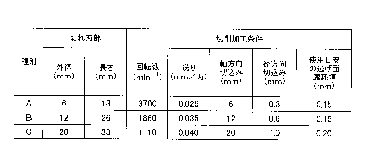
- the obtained round bar sintered body having a predetermined diameter is processed so as to have a predetermined size, and processed so as to have the cutting edge portion dimensions shown in Table 3, and is a table composed of a 6-blade square end mill.
- Cutting tools 1 to 10 made of the WC-based cemented carbide of the present invention (referred to as the present cemented carbide tool) 1 to 10 shown in FIG.
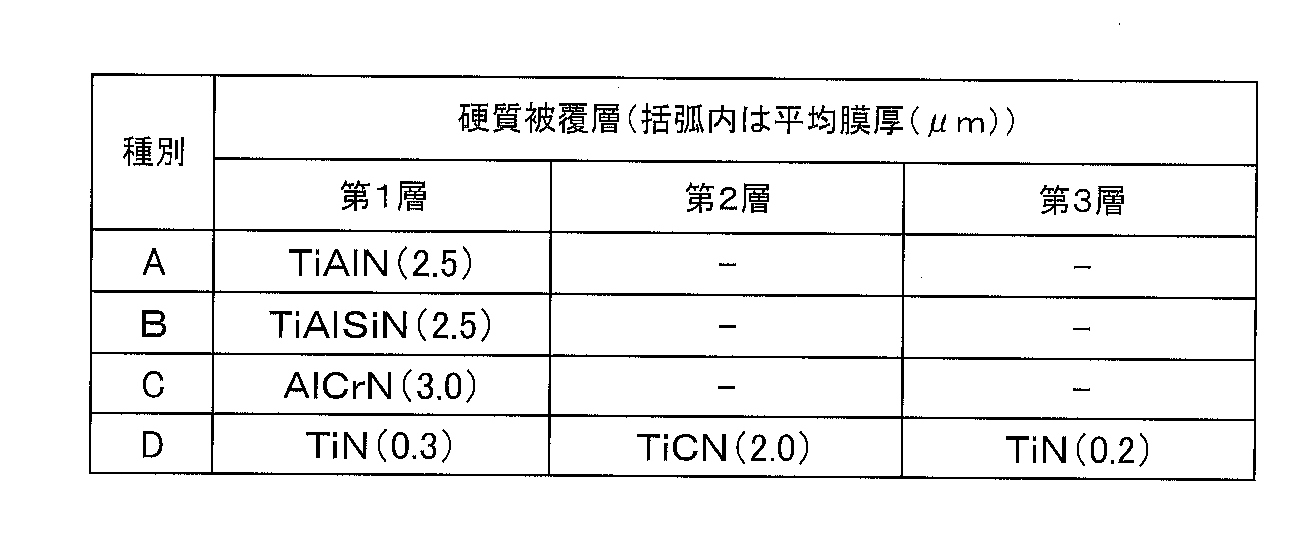
- a hard coating layer having the composition and average film thickness as shown in Table 4 is vapor-deposited on the surface of the tool base using an arc ion plating apparatus.
- a cutting tool made of the surface-coated WC-based cemented carbide of the present invention was produced.
- the raw material powder is blended so as to have the blending composition shown in Table 1, and the cutting edge dimensions shown in Table 3 are obtained by the same process as the cemented carbide tools 1 to 10 of the present invention.
- Processing was carried out to produce comparative example WC-based cemented carbide cutting tools (referred to as comparative example cemented carbide tools) 11 to 20 shown in Table 5 consisting of a 6-blade square end mill.
- a hard coating layer having a composition and an average film thickness as shown in Table 4 is vapor-deposited on the tool base surface using an arc ion plating apparatus.
- a comparative example surface-coated WC-based cemented carbide cutting tool was produced.
- the above-mentioned carbide tools 1 to 10 of the present invention and comparative carbide tools 12, 14, 17, and 20 were obtained by observing with a scanning electron microscope (SEM) equipped with a backscattering electron diffractometer (EBSD).
- SEM scanning electron microscope
- EBSD backscattering electron diffractometer
- the area of the WC grain was measured by image analysis of the crystal orientation mapping image of the WC grain, and the diameter when the WC was approximated to a circle having the same area was calculated.
- TEM transmission electron microscope
- EDS energy dispersive X-ray analyzer
- the Re content of the phase, the average Re content in the WC grains, and the thickness ratio (%) of the Re-enriched area (area where the Re content is 0.2 to 7% by mass) in the WC grain size It was measured.
- Table 6 shows the average value of the measurement results of 50 WC particles, the number of WC particles in which a Re-enriched region is formed in a depth region of 1 to 10% of the WC particle size, and Re in the entire WC particle.
- the number of WC particles contained and the average value of the Re content in the Re-enriched region are shown.
- the content of WC particles containing Re in the entire WC grain is 30% by number or less, and in a depth region of 1 to 10% of the WC grain size.
- the WC particles in which the Re-enriched regions are formed and the WC particles in which Re is contained in the entire WC grains are contained in a total of 90% by number or more.
- the average Re content in the enriched regions is 0.2 to It was within the range of 7% by mass.
- FIG. 1 the schematic diagram of the sintered compact structure
- the comparative cemented carbide tools 12 and 20 had a large amount of Re powder, so that the Re enriched region was formed.
- the average Re content in the enriched region is the amount specified in the present invention.
- the number of WC particles containing Re in the entire WC grains exceeded the amount specified in the present invention.
- the Re enriched region was formed, but the number of WC particles in which the enriched region was formed and the Re in the entire WC grain.
- the total number of WC particles contained was below the amount specified in the present invention, and the average Re content in the enriched region was below the amount specified in the present invention.
- a square material of a Ni-base alloy heat-resistant alloy (Cr: 18.5%, Mo: 3.0%, Al: 0.5%, Nb + Ta: 5.1%, balance: Ni and inevitable impurities) is used as a work material.
- a cutting test was performed under the various conditions shown in Fig. 3, and the cutting length until the flank wear width at the tip of the outer peripheral blade reached the value of the standard for use was measured. Moreover, this was observed about the abrasion condition of the cutting edge after a cutting test. The measurement results and observation results are shown in Table 5.
- the binder phase of the WC-based cemented carbide sintered body contains 3 to 20% by mass of solid solution Re and is hard.
- the average Re content in the Re-enriched region is 0.2 to 7% by mass, and the high temperature hardness is improved without causing a decrease in thermal conductivity, and the adhesion between the binder phase and the hard phase is improved.
- Co powders, Re powders, VC powders, Cr3C2 powders, TiC powders, TaC powders, NbC powders, and WC powders, all having an average particle diameter of 0.5 to 5 ⁇ m, are prepared as raw material powders.
- the powder was blended into the blending composition shown in Table 7, added with wax, wet mixed with a ball mill for 72 hours, dried under reduced pressure, and then pressed into a predetermined shape at a pressure of 100 MPa,
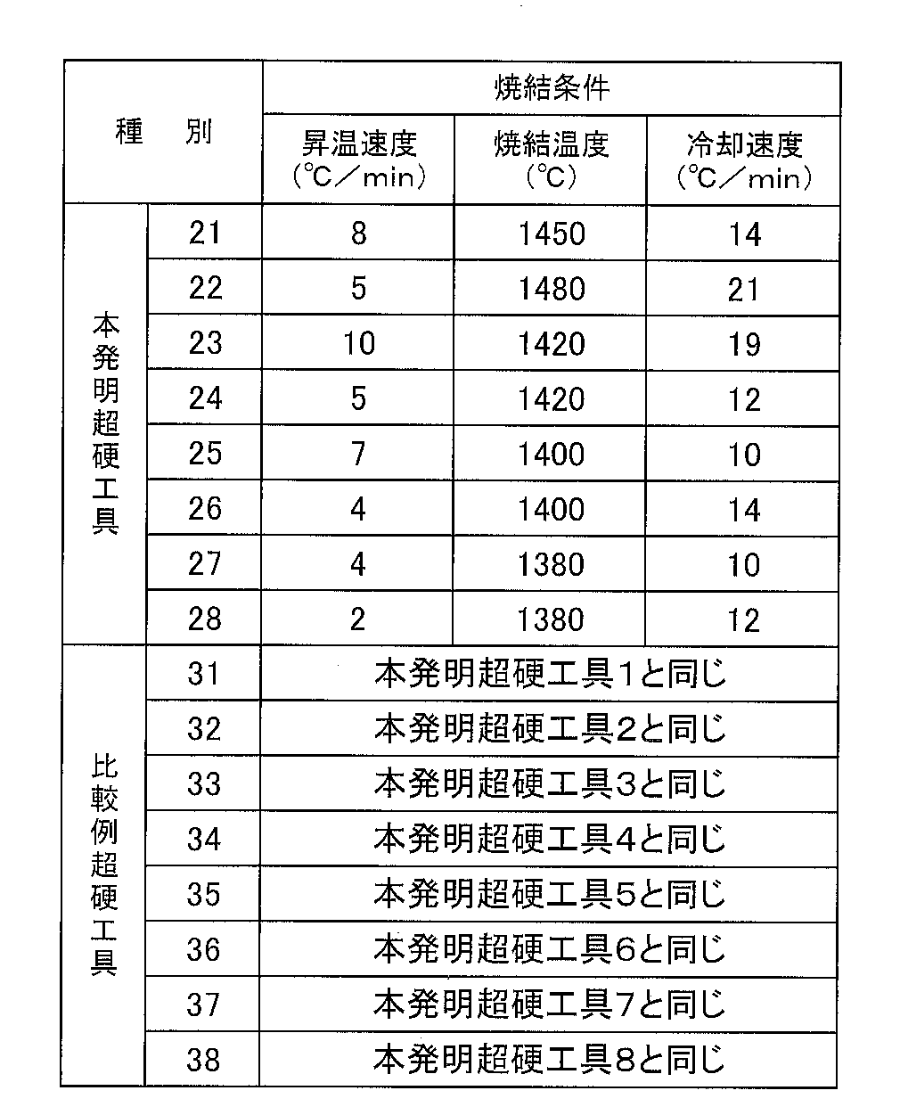
- B These green compacts are held at a sintering temperature shown in Table 8 in a vacuum of 1.3 Pa for 1 hour, and then Ar gas is introduced into the furnace to form a pressurized atmosphere of 6 MPa. For 1 hour, and then cooled to 900 ° C.
- the raw material powder was blended so as to have the blending composition shown in Table 7, and in the same manner as the cemented carbide tools 21 to 28 of the present invention, the comparative cemented carbide tool 31 having the insert shape of APMT1604PDER. ⁇ 38 were produced.
- a hard coating layer having the composition and average film thickness as shown in Table 4 is vapor-deposited on the tool base surface using an arc ion plating apparatus. As a result, a comparative example surface-coated WC-based cemented carbide cutting tool was produced.
- each of the cemented carbide tools 21 to 28 of the present invention a total of 90% by number or more of WC particles in which an enriched region of Re is formed in the vicinity of the interface in the WC grains and WC particles containing Re in the entire WC grains.
- the average Re content in the Re-enriched region was in the range of 0.2 to 7% by mass.
- each of the comparative carbides 33, 34, and 37 has the number of WC particles in which the Re-enriched region is formed in the vicinity of the interface in the WC grain, and the average Re content in the Re-enriched region. All were outside the range of the amount specified in the present invention.
- each of the cemented carbide tools 21 to 28 of the present invention and the comparative example cemented carbide tools 31 to 38 were fixed with screws to a cutter made of an alloy steel having a diameter of 32 mm, and a cutting test was performed under the following conditions.
- Work Material Ni-base alloy heat-resistant alloy (Cr: 18.5%, Mo: 3.0%, Al: 0.5%, Nb + Ta: 5.1%, balance: Ni and inevitable impurities),
- Cutting speed 40 m / min
- Radial depth of cut 1.0 mm
- Feeding 0.15mm / tooth
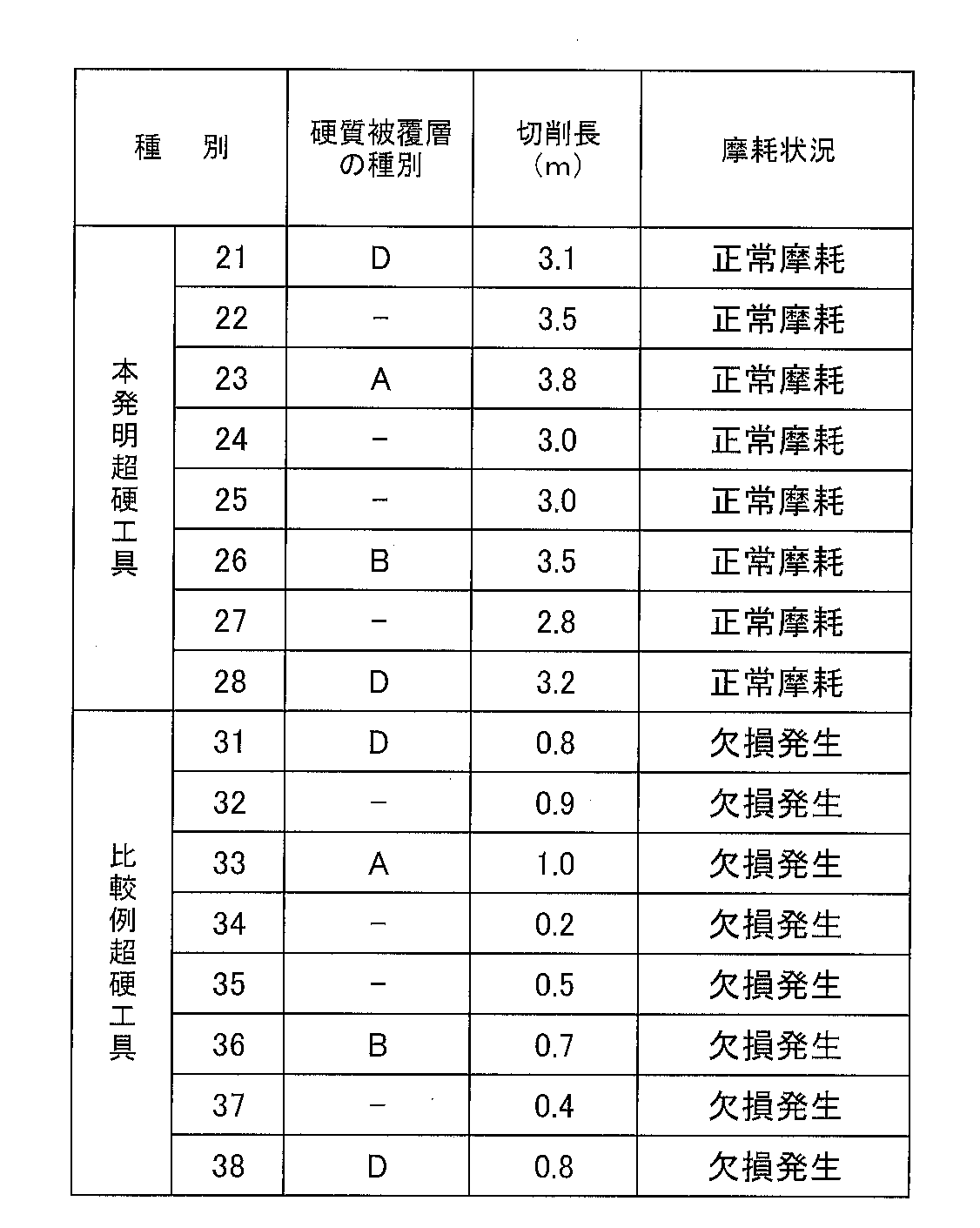
- Table 9 shows the measurement results and the observation results.
- the binder phase of the WC-based cemented carbide sintered body contains 3 to 20% by mass of solid solution Re and is hard.
- the average Re content in the Re-enriched region is 0.2 to 7% by mass, and the high temperature hardness is improved without causing a decrease in thermal conductivity, and the adhesion between the binder phase and the hard phase is improved.
- the comparative carbide tools 31 to 38 have cutting edges when used for cutting heat-resistant alloys such as Ni-base alloys and Co-base alloys whose cutting edges are locally exposed to high temperatures. It is clear that the defect of the part occurs and the service life is reached in a relatively short time.
- the WC-based cemented carbide cutting tool and the surface-coated WC-based cemented carbide cutting tool according to the present invention are not only used for cutting heat-resistant alloys such as Ni-based alloys and Co-based alloys, but also for various steels and cast irons.
- the present invention can be applied to cutting under the above conditions, and exhibits excellent cutting performance over a long period of use, and is suitable for labor saving and energy saving of cutting work and further cost reduction.
Landscapes
- Chemical & Material Sciences (AREA)
- Engineering & Computer Science (AREA)
- Materials Engineering (AREA)
- Mechanical Engineering (AREA)
- Metallurgy (AREA)
- Organic Chemistry (AREA)
- Powder Metallurgy (AREA)
- Cutting Tools, Boring Holders, And Turrets (AREA)
Abstract
Ni基合金、Co基合金等の耐熱合金の転削加工において、長期の使用にわたって、すぐれた耐欠損性を発揮する切削工具を提供する。 WC基超硬合金製切削工具において、結合相成分であるCoの含有量は4~12質量%、結合相中のRe含有量は3~20質量%であり、硬質相のWC粒内界面近傍にはReの富化領域が形成され、該富化領域は、WC粒子の表面から、その粒径の1~10%の深さ領域にわたって形成され、かつ、該領域における平均Re含有量は0.2~7質量%であって、また、必要に応じて、超硬合金の成分として、VC、Cr3C2、TiC、TaC、NbCを含有させ、あるいは、切削工具表面に硬質被覆層を蒸着形成する。
Description
この発明は、Ni基合金、Co基合金等の耐熱合金の切削加工において、長期の使用にわたって優れた耐欠損性を発揮するWC基超硬合金製切削工具(以下、WC基超硬工具という)および表面被覆WC基超硬合金製切削工具(以下、被覆WC基超硬工具という)に関するものである。
従来から、耐摩耗性に優れた切削工具としては、例えば、結合相形成成分としてCoを含有し、残りがWCおよび不可避不純物からなるWC基超硬合金、あるいは、さらに、VC、Cr3C2、TiC、TaC、NbCのうちから選ばれる少なくとも1種以上を含有するWC基超硬合金からなるWC基超硬工具が知られているが、工具特性をさらに高めるために、合金成分としてReをさらに含有させたWC基超硬工具も開発されている。
例えば、特許文献1には、原料粉末としてのW、C、Re等の粉末を混合・加熱処理した後、Co粉末等と混合して圧粉成形体を得て、その後焼結することにより、WC基超硬工具(従来超硬工具1という)を作製することが述べられており、この従来超硬工具1では、図2に示すように、硬質相を構成するWC粒子の粒子内部全体にわたって、0.1~3wt%程度のReがほぼ均一に固溶しており、このような組織を備えることによって、すぐれた靭性を発揮することが知られている。
また、特許文献2には、結合相中に25wt%以上のReを含有するWC基超硬合金を固相焼結することによってWC基超硬工具を作製することが示されており、このWC基超硬工具(従来超硬工具2という)では、図3に示すように、結合相中に高融点のRe成分が存在することから、高温硬さが向上することが知られている。
例えば、特許文献1には、原料粉末としてのW、C、Re等の粉末を混合・加熱処理した後、Co粉末等と混合して圧粉成形体を得て、その後焼結することにより、WC基超硬工具(従来超硬工具1という)を作製することが述べられており、この従来超硬工具1では、図2に示すように、硬質相を構成するWC粒子の粒子内部全体にわたって、0.1~3wt%程度のReがほぼ均一に固溶しており、このような組織を備えることによって、すぐれた靭性を発揮することが知られている。
また、特許文献2には、結合相中に25wt%以上のReを含有するWC基超硬合金を固相焼結することによってWC基超硬工具を作製することが示されており、このWC基超硬工具(従来超硬工具2という)では、図3に示すように、結合相中に高融点のRe成分が存在することから、高温硬さが向上することが知られている。
近年の切削装置の高性能化はめざましく、一方で切削加工に対する省力化および省エネ化、さらに、高能率化、低コスト化の要求は強く、また、切削工具の汎用化も求められているところであるが、例えば、特許文献1,2に示される従来超硬工具1、2を、通常条件の切削加工で用いた場合には特段の問題は生じない。
しかし、これを、特に、熱伝導率が小さく、切削加工時に切れ刃が高熱となるようなNi基合金、Co基合金等の耐熱合金の切削加工に用いた場合には、工具寿命の短命化が顕著となる。
つまり、例えば、従来超硬工具1では、全てのWC粒子内部にReが均一に固溶していることによって、WC粒子自体の靭性は向上するものの、その反面、WC粒子の熱伝導性が著しく低下するため、切刃部が過熱されやすくなり、その結果、熱塑性変形が発生しやすくなり、偏摩耗の発生を招きやすいという問題がある。
また、従来超硬工具2では、結合相中に多量のReが存在することから結合相の高温硬さが向上する半面、硬質相であるWC粒子と結合相との密着強度は低下し、さらに、Reが過剰に存在するような場合には、結合相自体の靭性が低下するために、チッピング、欠損を発生しやすくなるという問題が生じる。
しかし、これを、特に、熱伝導率が小さく、切削加工時に切れ刃が高熱となるようなNi基合金、Co基合金等の耐熱合金の切削加工に用いた場合には、工具寿命の短命化が顕著となる。
つまり、例えば、従来超硬工具1では、全てのWC粒子内部にReが均一に固溶していることによって、WC粒子自体の靭性は向上するものの、その反面、WC粒子の熱伝導性が著しく低下するため、切刃部が過熱されやすくなり、その結果、熱塑性変形が発生しやすくなり、偏摩耗の発生を招きやすいという問題がある。
また、従来超硬工具2では、結合相中に多量のReが存在することから結合相の高温硬さが向上する半面、硬質相であるWC粒子と結合相との密着強度は低下し、さらに、Reが過剰に存在するような場合には、結合相自体の靭性が低下するために、チッピング、欠損を発生しやすくなるという問題が生じる。
そこで、本発明者等は、上述のような観点から、Ni基合金、Co基合金等の耐熱合金等の切削加工に用いた場合でも、すぐれた耐欠損性、耐熱塑性変形性を発揮し、長期の使用に亘ってすぐれた切削性能を発揮するWC基超硬工具について鋭意研究を行った結果、以下の知見を得た。
通常、WC基超硬合金からなる焼結体の製造は、特定の平均粒径のWC粉末、Co粉末とともに、必要に応じて、VC粉末、Cr3C2粉末、TiC粉末、TaC粉末、NbC粉末を所定割合になるように配合した原料粉末を湿式ボールミル中で混合し、成形した後、この圧粉成形体を所定の温度で所定時間焼結することにより製造している。
本発明者らは、上記通常のWC基超硬合金焼結体の製造方法において、例えば、結合相形成成分であるCo粉末に加えて、所定の平均粒径および所定の含有割合となるようにRe粉末をさらに追加して添加配合することで原料粉末を調製し、これを1380~1500℃の範囲内の温度にて液相焼結し、さらに、所定の加圧雰囲気中で熱間静水圧プレス(HIP)成形し、その後、例えば、少なくとも900℃までを10℃/min以上の速度で冷却することによって、硬質相を構成するWC粒内の界面近傍に、Re富化領域が形成されると同時に、結合相中にも所定量のReが固溶することを見出したのである。
ここで、Reの富化領域とは、WC粒子の界面から、該WC粒子の粒径の1~10%の深さ領域にわたって平均Re含有量が0.2~7質量%であるReを含有する領域であり、Reの富化領域以外の領域、即ち、WC粒子の内部側では平均Re含有量は0.2質量%未満となっている。
そして、WC粒内の界面近傍に上記Reの富化領域が形成されたWC粒子が含有された焼結組織を有するWC基超硬合金から作製されたWC基超硬工具(以下、本発明超硬工具という)を用いて切削加工を行ったところ、高熱発生を伴うNi基合金、Co基合金等の耐熱合金の切削加工において、切刃部の過熱が抑制されるとともに、すぐれた耐欠損性、耐熱塑性変形性を発揮し、その結果、チッピング、偏摩耗等の発生を生じることなく長期の使用に亘ってすぐれた切削性能を発揮することを見出したのである。
ここで、Reの富化領域とは、WC粒子の界面から、該WC粒子の粒径の1~10%の深さ領域にわたって平均Re含有量が0.2~7質量%であるReを含有する領域であり、Reの富化領域以外の領域、即ち、WC粒子の内部側では平均Re含有量は0.2質量%未満となっている。
そして、WC粒内の界面近傍に上記Reの富化領域が形成されたWC粒子が含有された焼結組織を有するWC基超硬合金から作製されたWC基超硬工具(以下、本発明超硬工具という)を用いて切削加工を行ったところ、高熱発生を伴うNi基合金、Co基合金等の耐熱合金の切削加工において、切刃部の過熱が抑制されるとともに、すぐれた耐欠損性、耐熱塑性変形性を発揮し、その結果、チッピング、偏摩耗等の発生を生じることなく長期の使用に亘ってすぐれた切削性能を発揮することを見出したのである。
この発明は、上記の知見に基づいてなされたものであって、
「(1) 結合相成分としてCoを含有し、添加成分としてReを含有し、残部が硬質相成分としてのWCおよび不可避不純物からなるWC基超硬合金を工具基体とするWC基超硬合金製切削工具において、
結合相成分であるCoの含有量は4~12質量%であり、また、結合相中にはReが固溶しており、結合相中のRe含有量は3~20質量%であり、さらに、硬質相を構成するWC粒内の界面近傍にReの富化領域が形成されたWC粒子を含有することを特徴とするWC基超硬合金製切削工具。
(2) 上記WC基超硬合金中のReは、原料粉末としてRe粉末を配合することにより添加されたものであることを特徴とする前記(1)に記載のWC基超硬合金製切削工具。
(3) 上記WC基超硬合金製切削工具基体は、さらに、WC粒内全体にReが含有されたWC粒子を含有することを特徴とする前記(1)または(2)に記載のWC基超硬合金製切削工具。
(4) 上記WC粒内全体にReが含有されたWC粒子の含有量は、全WC粒子のうち30個数%以下であり、かつ、上記Re富化領域が形成されたWC粒子とWC粒内全体にReが含有されたWC粒子の合計が、上記WC基超硬合金製切削工具基体内の全WC粒子のうち90個数%以上含まれていることを特徴とする前記(3)に記載のWC基超硬合金製切削工具。
(5) 上記Reの富化領域は、WC粒子の界面から、該WC粒子の粒径の1~10%の深さ領域にわたって形成され、かつ、該深さ領域における平均Re含有量は0.2~7質量%であり、一方、WC粒子の内部側では、平均Re含有量は0.2質量%未満であることを特徴とする前記(1)乃至(4)のいずれかに記載のWC基超硬合金製切削工具。
(6) 上記WC基超硬合金製切削工具基体が、さらに、VC、Cr3C2、TiC、TaC、NbCのうちから選ばれる1種または2種以上を合計で0.1~2質量%含有することを特徴とする前記(1)乃至(5)のいずれかに記載のWC基超硬合金製切削工具。
(7) 前記(1)乃至(6)のいずれかに記載のWC基超硬合金製切削工具の表面に、硬質被覆層を蒸着形成してなる表面被覆WC基超硬合金製切削工具。」
に特徴を有するものである。
「(1) 結合相成分としてCoを含有し、添加成分としてReを含有し、残部が硬質相成分としてのWCおよび不可避不純物からなるWC基超硬合金を工具基体とするWC基超硬合金製切削工具において、
結合相成分であるCoの含有量は4~12質量%であり、また、結合相中にはReが固溶しており、結合相中のRe含有量は3~20質量%であり、さらに、硬質相を構成するWC粒内の界面近傍にReの富化領域が形成されたWC粒子を含有することを特徴とするWC基超硬合金製切削工具。
(2) 上記WC基超硬合金中のReは、原料粉末としてRe粉末を配合することにより添加されたものであることを特徴とする前記(1)に記載のWC基超硬合金製切削工具。
(3) 上記WC基超硬合金製切削工具基体は、さらに、WC粒内全体にReが含有されたWC粒子を含有することを特徴とする前記(1)または(2)に記載のWC基超硬合金製切削工具。
(4) 上記WC粒内全体にReが含有されたWC粒子の含有量は、全WC粒子のうち30個数%以下であり、かつ、上記Re富化領域が形成されたWC粒子とWC粒内全体にReが含有されたWC粒子の合計が、上記WC基超硬合金製切削工具基体内の全WC粒子のうち90個数%以上含まれていることを特徴とする前記(3)に記載のWC基超硬合金製切削工具。
(5) 上記Reの富化領域は、WC粒子の界面から、該WC粒子の粒径の1~10%の深さ領域にわたって形成され、かつ、該深さ領域における平均Re含有量は0.2~7質量%であり、一方、WC粒子の内部側では、平均Re含有量は0.2質量%未満であることを特徴とする前記(1)乃至(4)のいずれかに記載のWC基超硬合金製切削工具。
(6) 上記WC基超硬合金製切削工具基体が、さらに、VC、Cr3C2、TiC、TaC、NbCのうちから選ばれる1種または2種以上を合計で0.1~2質量%含有することを特徴とする前記(1)乃至(5)のいずれかに記載のWC基超硬合金製切削工具。
(7) 前記(1)乃至(6)のいずれかに記載のWC基超硬合金製切削工具の表面に、硬質被覆層を蒸着形成してなる表面被覆WC基超硬合金製切削工具。」
に特徴を有するものである。
この発明のWC基超硬工具について、以下に詳細に説明する。
この発明のWC基超硬工具は、例えば、WC粉末、Co粉末に加えてRe粉末を配合し、さらに、必要に応じて、VC粉末、Cr3C2粉末、TiC粉末、TaC粉末、NbC粉末を所定割合になるように配合した原料粉末を、湿式ボールミル中で混合し、所定形状にプレス成形したのち、この圧粉成形体を、1~15Paの真空中で、1380~1500℃の範囲内の所定の温度にて液相焼結し、次いで、例えばArガスを導入して3~15MPaとした加圧雰囲気中で熱間静水圧プレス(HIP)成形し、その後、例えば、少なくとも900℃までを10℃/min以上の速度で冷却することによって製造することができる。
そして、上記の製造工程で作製した本発明WC基超硬工具は、結合相中に3~20質量%のReが固溶されているとともに、WC粒子の界面から、該WC粒子の粒径の1~10%の深さ領域にわたって、平均Re含有量が0.2~7質量%であるReの富化領域が形成されたWC粒子を有しており、また、該Re富化領域の内側、即ち、WC粒子の内部側では平均Re含有量は0.2質量%未満となっている。
そして、このような組織が形成された本発明WC基超硬工具は、Reが主としてWC粒子界面近傍に存在することから、WC粒子の熱伝導性を大きく低下させることはなく、また、結合相中にReが固溶されていることから結合相の高温硬さが向上し、さらに、WC粒内の界面近傍に形成されているRe富化領域によって、WC粒子と結合相との密着強度が高められる。
この発明のWC基超硬工具は、例えば、WC粉末、Co粉末に加えてRe粉末を配合し、さらに、必要に応じて、VC粉末、Cr3C2粉末、TiC粉末、TaC粉末、NbC粉末を所定割合になるように配合した原料粉末を、湿式ボールミル中で混合し、所定形状にプレス成形したのち、この圧粉成形体を、1~15Paの真空中で、1380~1500℃の範囲内の所定の温度にて液相焼結し、次いで、例えばArガスを導入して3~15MPaとした加圧雰囲気中で熱間静水圧プレス(HIP)成形し、その後、例えば、少なくとも900℃までを10℃/min以上の速度で冷却することによって製造することができる。
そして、上記の製造工程で作製した本発明WC基超硬工具は、結合相中に3~20質量%のReが固溶されているとともに、WC粒子の界面から、該WC粒子の粒径の1~10%の深さ領域にわたって、平均Re含有量が0.2~7質量%であるReの富化領域が形成されたWC粒子を有しており、また、該Re富化領域の内側、即ち、WC粒子の内部側では平均Re含有量は0.2質量%未満となっている。
そして、このような組織が形成された本発明WC基超硬工具は、Reが主としてWC粒子界面近傍に存在することから、WC粒子の熱伝導性を大きく低下させることはなく、また、結合相中にReが固溶されていることから結合相の高温硬さが向上し、さらに、WC粒内の界面近傍に形成されているRe富化領域によって、WC粒子と結合相との密着強度が高められる。
本発明WC基超硬工具において結合相を構成するCo成分は、その含有量が4質量%未満では、WC基超硬合金の緻密化が十分になされず、一方、結合相の含有割合が12質量%を越えると、WC基超硬合金の硬度が低下し、Ni基合金、Co基合金等の耐熱合金の切削加工において耐摩耗性が低下傾向を示すようになることから、本発明WC基超硬合金焼結体における結合相の含有割合は4~12質量%と定めた。
また、本発明で、WC粉末、Co粉末とともに配合するRe粉末は結合相を構成するCoに大部分が(3~20質量%)固溶し、一部がWC粒内の界面近傍に含有され、Re富化領域を形成するが、Coに固溶するRe含有量(Re/(Co+Re))が3質量%未満であると、WC粒と結合相の密着性向上効果及び結合相の硬さ向上効果が不十分であり、一方、Coに固溶するRe含有量(Re/(Co+Re))が20質量%を超えると、結合相の靭性が著しく低下するため破壊靱性値が低下し、耐熱合金の切削においてチッピングを発生しやすくなることから、Coに固溶するRe含有量(Re/(Co+Re))は3~20質量%と定めた。
また、本発明では、WC粒内の界面近傍にReの富化領域を形成し、該Re富化領域については、WC粒子の粒径の1~10%の深さ領域にわたって形成され、かつ、深さ領域における平均Re含有量(Re/(W+Re))は0.2~7質量%であるとしているが、WC粒子の粒径の1~10%の深さ領域におけるRe含有量が0.2質量%未満では、WC粒と結合相の密着性向上効果が得られず、一方、Re含有量が7質量%を超えるようになると、WC粒子の熱伝導性が著しく低下するため切れ刃が過熱されやすくなり、その結果、熱塑性変形が発生しやすくなることから、Re富化領域、即ち、WC粒子の粒径の1~10%の深さ領域における平均Re含有量(Re/(W+Re))は0.2~7質量%と定めた。
なお、「WC粒子の粒径の1~10%の深さ領域」を別の表現で定義すれば、後方散乱電子回折装置(EBSD)を備えた走査型電子顕微鏡(SEM)で観察されたWC粒子の結晶方位マッピング像を、同一面積の円形に近似した時の直径をWC粒径とした場合に、WC粒の界面から該WC粒径の1~10%の深さ領域ということになる。
なお、「WC粒子の粒径の1~10%の深さ領域」を別の表現で定義すれば、後方散乱電子回折装置(EBSD)を備えた走査型電子顕微鏡(SEM)で観察されたWC粒子の結晶方位マッピング像を、同一面積の円形に近似した時の直径をWC粒径とした場合に、WC粒の界面から該WC粒径の1~10%の深さ領域ということになる。
本発明では、WC粒内の界面近傍にReの富化領域が形成されたWC粒子のほかに、WC粒内全体にReが含有されたWC粒子が含まれていても、WC粒と結合相の密着性向上効果を妨げることはないが、その含有量が全WC粒子のうち30個数%を超えると、熱伝導性が著しく低下するため切れ刃が過熱されやすくなり、その結果、熱塑性変形が発生しやすくなることから、WC粒内全体にReが含有されたWC粒子の含有量は、全WC粒子のうち30個数%以下と定めた。
また、WC粒内の界面近傍にReの富化領域が形成されたWC粒子とWC粒内全体にReが含有されたWC粒子の含有量の合計が、全WC粒子のうち90個数%未満になると、WC粒と結合相の密着性向上効果が得られなくなることから、WC粒内の界面近傍にReの富化領域が形成されたWC粒子とWC粒内全体にReが含有されたWC粒子の含有量の合計は、全WC粒子のうち90個数%以上と定めた。
また、WC粒内の界面近傍にReの富化領域が形成されたWC粒子とWC粒内全体にReが含有されたWC粒子の含有量の合計が、全WC粒子のうち90個数%未満になると、WC粒と結合相の密着性向上効果が得られなくなることから、WC粒内の界面近傍にReの富化領域が形成されたWC粒子とWC粒内全体にReが含有されたWC粒子の含有量の合計は、全WC粒子のうち90個数%以上と定めた。
本発明WC基超硬工具では、VC、Cr3C2、TiC、TaC、NbCのうちから選ばれる1種または2種以上の成分を含有することができる。
VC、Cr3C2、TiC、TaC、NbCのうちから選ばれる1種または2種以上の成分は、いずれも、焼結時のWCの粒成長を抑制する作用があるが、その合計含有量が0.1質量%未満では、粒成長抑制作用が小さく、一方、2質量%を越えて含有すると複合炭化物相が析出し、硬度が低下傾向を示すようになるので、VC、Cr3C2、TiC、TaC、NbCのうちから選ばれる1種または2種以上の成分の含有量は、その合計量で0.1~2質量%と定めた。
VC、Cr3C2、TiC、TaC、NbCのうちから選ばれる1種または2種以上の成分は、いずれも、焼結時のWCの粒成長を抑制する作用があるが、その合計含有量が0.1質量%未満では、粒成長抑制作用が小さく、一方、2質量%を越えて含有すると複合炭化物相が析出し、硬度が低下傾向を示すようになるので、VC、Cr3C2、TiC、TaC、NbCのうちから選ばれる1種または2種以上の成分の含有量は、その合計量で0.1~2質量%と定めた。
また、本発明WC基超硬工具は、これをそのまま切削工具として用いることができるが、その表面に硬質被覆層を蒸着形成することによって、一段と耐欠損性、耐熱塑性変形性の向上を図ることができ、工具寿命の一層の延命化を図ることができるのである。
ここで、上記硬質被覆層とは、例えば、「周期律表のIVa族元素、Va族元素、VIa族元素、Al、BおよびSiからなる群から選ばれる少なくとも1種の元素と、炭素、窒素および酸素からなる群から選ばれる少なくとも1種の元素とを含む化合物」からなり、また、より具体的には、例えば、Tiの炭化物、窒化物、炭窒化物、TiとAlの複合窒化物、AlとCrの複合窒化物、TiとSiの複合窒化物、TiとAlとSiの複合窒化物のうちから選ばれる1種の単層または2種以上の複層からなる。
ここで、上記硬質被覆層とは、例えば、「周期律表のIVa族元素、Va族元素、VIa族元素、Al、BおよびSiからなる群から選ばれる少なくとも1種の元素と、炭素、窒素および酸素からなる群から選ばれる少なくとも1種の元素とを含む化合物」からなり、また、より具体的には、例えば、Tiの炭化物、窒化物、炭窒化物、TiとAlの複合窒化物、AlとCrの複合窒化物、TiとSiの複合窒化物、TiとAlとSiの複合窒化物のうちから選ばれる1種の単層または2種以上の複層からなる。
この発明のWC基超硬工具、表面被覆WC基超硬工具は、これを構成するWC基超硬合金の結合相中にReが固溶し高温硬さを高めるとともに、硬質相を構成するWC粒内の界面近傍にReの富化領域が形成されたWCが含有されていることにより、WC粒子の有する熱伝導率を低下させることなく、さらに、結合相と硬質相との密着強度を高めることから、耐欠損性及び耐熱塑性変形性に優れ、切刃部が局部的に高温に曝されるNi基合金、Co基合金等の耐熱合金等の切削加工に用いた場合でも、欠損、偏摩耗等の発生を生じることなく長期の使用に亘ってすぐれた切削性能を発揮するものである。
つぎに、この発明の切削工具を実施例により具体的に説明する。
(a)原料粉末として、いずれも0.5~5μmの平均粒径を有する、Co粉末、Re粉末、VC粉末、Cr3C2粉末、TiC粉末、TaC粉末、NbC粉末、WC粉末を用意し、これら原料粉末を、表1に示される配合組成に配合し、さらにワックスを加えてボールミルで72時間湿式混合し、減圧乾燥した後、100MPaの圧力で8~26mmの範囲内の所定の直径を有する丸棒圧粉体をプレス成形し、
(b)これらの圧粉成形体を、1.3Paの真空中で表2に示される焼結温度で1時間保持し、次いで、炉内にArガスを導入して6MPaの加圧雰囲気とするとともにさらに1時間保持し、次いで、900℃までを表2で示される冷却速度で冷却するとともに、その後は室温にまで炉冷し、
(c)得られた所定直径の丸棒焼結体を、所定寸法となるように加工して、表3に示す切れ刃部寸法となるように加工して、6枚刃スクエアエンドミルからなる表5に示す本発明WC基超硬合金製切削工具(本発明超硬工具という)1~10を作製した。
なお、本発明超硬工具3,6,10については、工具基体表面に、アークイオンプレーティング装置を用いて、表4に示されるとおりの組成および平均膜厚の硬質被覆層を蒸着形成することにより、本発明表面被覆WC基超硬合金製切削工具を作製した。
(b)これらの圧粉成形体を、1.3Paの真空中で表2に示される焼結温度で1時間保持し、次いで、炉内にArガスを導入して6MPaの加圧雰囲気とするとともにさらに1時間保持し、次いで、900℃までを表2で示される冷却速度で冷却するとともに、その後は室温にまで炉冷し、
(c)得られた所定直径の丸棒焼結体を、所定寸法となるように加工して、表3に示す切れ刃部寸法となるように加工して、6枚刃スクエアエンドミルからなる表5に示す本発明WC基超硬合金製切削工具(本発明超硬工具という)1~10を作製した。
なお、本発明超硬工具3,6,10については、工具基体表面に、アークイオンプレーティング装置を用いて、表4に示されるとおりの組成および平均膜厚の硬質被覆層を蒸着形成することにより、本発明表面被覆WC基超硬合金製切削工具を作製した。
また、比較の目的で、表1に示される配合組成となるように原料粉末を配合し、本発明超硬工具1~10と同様な工程により、表3に示す切れ刃部寸法となるように加工して、6枚刃スクエアエンドミルからなる表5に示す比較例WC基超硬合金製切削工具(比較例超硬工具という)11~20を作製した。
なお、比較例超硬工具13,16,20については、工具基体表面に、アークイオンプレーティング装置を用いて、表4に示されるとおりの組成および平均膜厚の硬質被覆層を蒸着形成することにより、比較例表面被覆WC基超硬合金製切削工具を作製した。
なお、比較例超硬工具13,16,20については、工具基体表面に、アークイオンプレーティング装置を用いて、表4に示されるとおりの組成および平均膜厚の硬質被覆層を蒸着形成することにより、比較例表面被覆WC基超硬合金製切削工具を作製した。
上記本発明超硬工具1~10および比較例超硬工具12、14、17、20について、後方散乱電子回折装置(EBSD)を備えた走査型電子顕微鏡(SEM)にて観察し、得られたWC粒の結晶方位マッピング像の画像解析によりWC粒の面積を測定し、さらに該WCを同一面積の円形に近似した時の直径を算出した。また、エネルギー分散型X線分析装置(EDS)を備えた透過型電子顕微鏡(TEM)を用い、WC粒と結合相の界面からWC粒の内部に向かって、2nm毎に点分析を行い、結合相のRe含有量、WC粒内の平均Re含有量、WC粒子の粒径に占めるRe富化領域(Re含有量が0.2~7質量%である領域)の厚さ比(%)を測定した。
表6には、WC粒子50個の測定結果の各平均値と、WC粒径の1~10%の深さ領域にRe富化領域が形成されたWC粒子数、WC粒内全体にReが含有されたWC粒子数、および該Re富化領域におけるRe含有量の平均値を示した。
本発明超硬工具1~10はいずれも、WC粒内全体にReが含有されたWC粒子の含有量は30個数%以下であり、かつ、WC粒径の1~10%の深さ領域にRe富化領域が形成されたWC粒子と、WC粒内全体にReが含有されたWC粒子が合計で90個数%以上含有されており、該富化領域における平均Re含有量は0.2~7質量%の範囲内であった。
図1には、一例として、本発明超硬工具3の焼結体組織の模式図を示す。
これに対して比較例超硬工具12、20は、Re粉末の配合量が多かったため、Re富化領域が形成されたものの、該富化領域における平均Re含有量は、本発明で規定する量を超えるものであり、さらに、WC粒内全体にReが含有されたWC粒子数は本発明で規定する量を超えるものであった。
また、比較例超硬工具14、17は、Re粉末の配合量が少なかったため、Re富化領域は形成されたものの、該富化領域が形成されたWC粒子数とWC粒内全体にReが含有されたWC粒子数の合計は、本発明で規定する量を下回るものであり、さらに、該富化領域における平均Re含有量は、本発明で規定する量を下回るものであった。
表6には、WC粒子50個の測定結果の各平均値と、WC粒径の1~10%の深さ領域にRe富化領域が形成されたWC粒子数、WC粒内全体にReが含有されたWC粒子数、および該Re富化領域におけるRe含有量の平均値を示した。
本発明超硬工具1~10はいずれも、WC粒内全体にReが含有されたWC粒子の含有量は30個数%以下であり、かつ、WC粒径の1~10%の深さ領域にRe富化領域が形成されたWC粒子と、WC粒内全体にReが含有されたWC粒子が合計で90個数%以上含有されており、該富化領域における平均Re含有量は0.2~7質量%の範囲内であった。
図1には、一例として、本発明超硬工具3の焼結体組織の模式図を示す。
これに対して比較例超硬工具12、20は、Re粉末の配合量が多かったため、Re富化領域が形成されたものの、該富化領域における平均Re含有量は、本発明で規定する量を超えるものであり、さらに、WC粒内全体にReが含有されたWC粒子数は本発明で規定する量を超えるものであった。
また、比較例超硬工具14、17は、Re粉末の配合量が少なかったため、Re富化領域は形成されたものの、該富化領域が形成されたWC粒子数とWC粒内全体にReが含有されたWC粒子数の合計は、本発明で規定する量を下回るものであり、さらに、該富化領域における平均Re含有量は、本発明で規定する量を下回るものであった。




つぎに、上記本発明超硬工具1~10、比較例超硬工具11~20について、
Ni基合金耐熱合金(Cr:18.5%,Mo:3.0%,Al:0.5%,Nb+Ta:5.1%,残部:Niおよび不可避不純物)の角材を被削材として、表3に示す各種条件で切削加工試験を行い、外周刃の先端部における逃げ面摩耗幅が使用目安の値に至るまでの切削長を測定した。
また、切削加工試験後の切れ刃の摩耗状況について、これを観察した。
この測定結果、観察結果を表5に示した。
Ni基合金耐熱合金(Cr:18.5%,Mo:3.0%,Al:0.5%,Nb+Ta:5.1%,残部:Niおよび不可避不純物)の角材を被削材として、表3に示す各種条件で切削加工試験を行い、外周刃の先端部における逃げ面摩耗幅が使用目安の値に至るまでの切削長を測定した。
また、切削加工試験後の切れ刃の摩耗状況について、これを観察した。
この測定結果、観察結果を表5に示した。
表5、表6に示される結果から、本発明超硬工具1~10は、WC基超硬合金焼結体の結合相が、3~20質量%の固溶Reを含有し、また、硬質相のWC粒内の界面近傍にReの富化領域が形成されたWC粒子とWC粒内全体にReが含有されたWC粒子を合計で、全WC粒子のうちの90個数%以上含有し、かつ、該Re富化領域における平均Re含有量が0.2~7質量%であって、熱伝導性の低下を招くことなく、高温硬さが向上し、また、結合相と硬質相の密着強度も高くなり、耐欠損性に優れ、かつ、耐熱塑性変形性にも優れることから、切刃部が局部的に高温に曝されるNi基合金、Co基合金等の耐熱合金の切削加工に用いた場合でも、欠損、偏摩耗等を発生することなく長期の使用に亘ってすぐれた耐摩耗性を発揮する。
これに対して、比較例超硬工具11~20においては、切刃部が局部的に高温に曝されるNi基合金、Co基合金等の耐熱合金の切削加工に用いた場合には、切刃部の欠損が発生し、また、耐摩耗性にも劣り、比較的短時間で使用寿命に至ることが明らかである。
これに対して、比較例超硬工具11~20においては、切刃部が局部的に高温に曝されるNi基合金、Co基合金等の耐熱合金の切削加工に用いた場合には、切刃部の欠損が発生し、また、耐摩耗性にも劣り、比較的短時間で使用寿命に至ることが明らかである。
(a)原料粉末として、いずれも0.5~5μmの平均粒径を有する、Co粉末、Re粉末、VC粉末、Cr3C2粉末、TiC粉末、TaC粉末、NbC粉末、WC粉末を用意し、これら原料粉末を、表7に示される配合組成に配合し、さらにワックスを加えてボールミルで72時間湿式混合し、減圧乾燥した後、100MPaの圧力で所定形状にプレス成形し、
(b)これらの圧粉成形体を、1.3Paの真空中で表8に示される焼結温度で1時間保持し、次いで、炉内にArガスを導入して6MPaの加圧雰囲気とするとともにさらに1時間保持し、次いで、900℃までを表8で示される冷却速度で冷却するとともに、その後は炉冷し、
(c)得られた焼結体を、所定寸法となるように加工して、APMT1604PDERのインサート形状をもった本発明超硬工具21~28を作製した。
なお、本発明超硬工具21,23,26,28については、工具基体表面に、アークイオンプレーティング装置を用いて、表4に示されるとおりの組成および平均膜厚の硬質被覆層を蒸着形成することにより、表9に示す本発明表面被覆WC基超硬合金製切削工具を作製した。
(b)これらの圧粉成形体を、1.3Paの真空中で表8に示される焼結温度で1時間保持し、次いで、炉内にArガスを導入して6MPaの加圧雰囲気とするとともにさらに1時間保持し、次いで、900℃までを表8で示される冷却速度で冷却するとともに、その後は炉冷し、
(c)得られた焼結体を、所定寸法となるように加工して、APMT1604PDERのインサート形状をもった本発明超硬工具21~28を作製した。
なお、本発明超硬工具21,23,26,28については、工具基体表面に、アークイオンプレーティング装置を用いて、表4に示されるとおりの組成および平均膜厚の硬質被覆層を蒸着形成することにより、表9に示す本発明表面被覆WC基超硬合金製切削工具を作製した。
また、比較の目的で、表7に示される配合組成となるように原料粉末を配合し、本発明超硬工具21~28と同様にして、APMT1604PDERのインサート形状をもった比較例超硬工具31~38を作製した。
なお、比較例超硬工具31、33、36、38については、工具基体表面に、アークイオンプレーティング装置を用いて、表4に示されるとおりの組成および平均膜厚の硬質被覆層を蒸着形成することにより、比較例表面被覆WC基超硬合金製切削工具を作製した。
なお、比較例超硬工具31、33、36、38については、工具基体表面に、アークイオンプレーティング装置を用いて、表4に示されるとおりの組成および平均膜厚の硬質被覆層を蒸着形成することにより、比較例表面被覆WC基超硬合金製切削工具を作製した。
上記本発明超硬工具21~28および比較例超硬33、34、37について、実施例1の場合と同様に、TEM-EDSによる点分析を行い、焼結組織の結合相中のRe含有量、WC粒子の平均粒径、WC粒径の1~10%の深さ領域にRe富化領域が形成されたWC粒子数、WC粒内全体にReが含有されたWC粒子数、形成されたRe富化領域における平均Re含有量を測定した。
表10には、WC粒子50個の測定結果の各平均値を示した。
本発明超硬工具21~28はいずれも、WC粒内の界面近傍にReの富化領域が形成されたWC粒子とWC粒内全体にReが含有されたWC粒子を合計で90個数%以上含有し、該Re富化領域における平均Re含有量は0.2~7質量%の範囲内であった。
これに対して、比較例超硬33、34、37はいずれも、WC粒内の界面近傍にReの富化領域が形成されたWC粒子数、および該Re富化領域における平均Re含有量のいずれも本発明で規定する量の範囲外であった。
表10には、WC粒子50個の測定結果の各平均値を示した。
本発明超硬工具21~28はいずれも、WC粒内の界面近傍にReの富化領域が形成されたWC粒子とWC粒内全体にReが含有されたWC粒子を合計で90個数%以上含有し、該Re富化領域における平均Re含有量は0.2~7質量%の範囲内であった。
これに対して、比較例超硬33、34、37はいずれも、WC粒内の界面近傍にReの富化領域が形成されたWC粒子数、および該Re富化領域における平均Re含有量のいずれも本発明で規定する量の範囲外であった。


つぎに、上記本発明超硬工具21~28および比較例超硬工具31~38のそれぞれを、直径32mmの合金鋼製のカッターにねじ止め固定し、以下の条件で切削加工試験を行った。
被削材 :Ni基合金耐熱合金(Cr:18.5%,Mo:3.0%,Al:0.5%,Nb+Ta:5.1%,残部:Niおよび不可避不純物)の角材、
切削速度 : 40m/min、
軸歩行切込み: 5.0mm、
径方向切込み: 1.0mm、
送り : 0.15mm/刃
上記切削加工試験において、逃げ面摩耗幅が0.2mmに達するまでの切削長を測定し、また、切削加工試験後の切れ刃の摩耗状況を観察した。
この測定結果、観察結果を表9に示した。
被削材 :Ni基合金耐熱合金(Cr:18.5%,Mo:3.0%,Al:0.5%,Nb+Ta:5.1%,残部:Niおよび不可避不純物)の角材、
切削速度 : 40m/min、
軸歩行切込み: 5.0mm、
径方向切込み: 1.0mm、
送り : 0.15mm/刃
上記切削加工試験において、逃げ面摩耗幅が0.2mmに達するまでの切削長を測定し、また、切削加工試験後の切れ刃の摩耗状況を観察した。
この測定結果、観察結果を表9に示した。
表9、表10に示される結果から、本発明超硬工具21~28は、WC基超硬合金焼結体の結合相が、3~20質量%の固溶Reを含有し、また、硬質相のWC粒内の界面近傍にReの富化領域が形成されたWC粒子とWC粒内全体にReが含有されたWC粒子を合計で、全WC粒子のうちの90個数%以上含有し、かつ、該Re富化領域における平均Re含有量が0.2~7質量%であって、熱伝導性の低下を招くことなく、高温硬さが向上し、また、結合相と硬質相の密着強度も高くなり、耐欠損性に優れ、かつ、耐熱塑性変形性にも優れることから、切刃部が局部的に高温に曝されるNi基合金、Co基合金等の耐熱合金の切削加工に用いた場合でも、欠損、偏摩耗等を発生することなく長期の使用に亘ってすぐれた耐摩耗性を発揮する。
これに対して、比較例超硬工具31~38は、切刃部が局部的に高温に曝されるNi基合金、Co基合金等の耐熱合金の切削加工に用いた場合には、切刃部の欠損が発生し、比較的短時間で使用寿命に至ることが明らかである。
これに対して、比較例超硬工具31~38は、切刃部が局部的に高温に曝されるNi基合金、Co基合金等の耐熱合金の切削加工に用いた場合には、切刃部の欠損が発生し、比較的短時間で使用寿命に至ることが明らかである。
この発明のWC基超硬合金製切削工具、表面被覆WC基超硬合金製切削工具は、Ni基合金、Co基合金等の耐熱合金の切削加工ばかりでなく、各種の鋼や鋳鉄などの通常の条件での切削加工にも勿論適用可能であり、長期の使用に亘ってすぐれた切削性能を発揮し、切削加工の省力化および省エネ化、さらに低コスト化に適うものである。
Claims (7)
- 結合相成分としてCoを含有し、添加成分としてReを含有し、残部が硬質相成分としてのWCおよび不可避不純物からなるWC基超硬合金を工具基体とするWC基超硬合金製切削工具において、
結合相成分であるCoの含有量は4~12質量%であり、また、結合相中にはReが固溶しており、結合相中のRe含有量は3~20質量%であり、さらに、硬質相を構成するWC粒内の界面近傍にReの富化領域が形成されたWC粒子を含有することを特徴とするWC基超硬合金製切削工具。
- 上記WC基超硬合金中のReは、原料粉末としてRe粉末を配合することにより添加されたものであることを特徴とする請求項1に記載のWC基超硬合金製切削工具。
- 上記WC基超硬合金製切削工具基体は、さらに、WC粒内全体にReが含有されたWC粒子を含有することを特徴とする請求項1または2に記載のWC基超硬合金製切削工具。
- 上記WC粒内全体にReが含有されたWC粒子の含有量は、全WC粒子のうち30個数%以下であり、かつ、上記Re富化領域が形成されたWC粒子とWC粒内全体にReが含有されたWC粒子の合計が、上記WC基超硬合金製切削工具基体内の全WC粒子のうち90個数%以上含まれていることを特徴とする請求項3に記載のWC基超硬合金製切削工具。
- 上記Reの富化領域は、WC粒子の界面から、該WC粒子の粒径の1~10%の深さ領域にわたって形成され、かつ、該深さ領域における平均Re含有量は0.2~7質量%であり、一方、WC粒子の内部側では、平均Re含有量は0.2質量%未満であることを特徴とする請求項1乃至4のいずれか一項に記載のWC基超硬合金製切削工具。
- 上記WC基超硬合金製切削工具基体が、さらに、VC、Cr3C2、TiC、TaC、NbCのうちから選ばれる1種または2種以上を合計で0.1~2質量%含有することを特徴とする請求項1乃至5のいずれか一項に記載のWC基超硬合金製切削工具。
- 請求項1乃至6のいずれか一項に記載のWC基超硬合金製切削工具の表面に、硬質被覆層を蒸着形成してなる表面被覆WC基超硬合金製切削工具。
Applications Claiming Priority (2)
| Application Number | Priority Date | Filing Date | Title |
|---|---|---|---|
| JP2010234391A JP5652113B2 (ja) | 2010-10-19 | 2010-10-19 | 耐熱合金の切削加工で優れた耐欠損性を発揮するwc基超硬合金製切削工具および表面被覆wc基超硬合金製切削工具 |
| JP2010-234391 | 2010-10-19 |
Publications (1)
| Publication Number | Publication Date |
|---|---|
| WO2012053237A1 true WO2012053237A1 (ja) | 2012-04-26 |
Family
ID=45974965
Family Applications (1)
| Application Number | Title | Priority Date | Filing Date |
|---|---|---|---|
| PCT/JP2011/057936 Ceased WO2012053237A1 (ja) | 2010-10-19 | 2011-03-30 | 耐熱合金の切削加工で優れた耐欠損性を発揮するwc基超硬合金製切削工具および表面被覆wc基超硬合金製切削工具 |
Country Status (2)
| Country | Link |
|---|---|
| JP (1) | JP5652113B2 (ja) |
| WO (1) | WO2012053237A1 (ja) |
Cited By (9)
| Publication number | Priority date | Publication date | Assignee | Title |
|---|---|---|---|---|
| CN103741001A (zh) * | 2014-01-16 | 2014-04-23 | 河源普益硬质合金厂有限公司 | 高硬度高强度py30t硬质合金及其合金制品的制备方法 |
| RU2521747C1 (ru) * | 2012-12-12 | 2014-07-10 | Анатолий Матвеевич Адаскин | Твердый сплав на основе карбида вольфрама для обработки резанием труднообрабатываемых материалов |
| CN106756394A (zh) * | 2017-01-09 | 2017-05-31 | 株洲精特硬质合金有限公司 | 超耐磨高硬度硬质合金钻具材料及其制备方法 |
| CN107287472A (zh) * | 2016-04-13 | 2017-10-24 | 沈阳拓普新材料有限公司 | 钴基含铌含铜粉末冶金法化纤切断刀的制造 |
| CN107955898A (zh) * | 2016-10-14 | 2018-04-24 | 刘立凡 | 硬质合金材料及其制造方法 |
| CN111378857A (zh) * | 2018-12-28 | 2020-07-07 | 自贡硬质合金有限责任公司 | 一种高性能超细晶硬质合金制备方法 |
| CN114959400A (zh) * | 2022-04-21 | 2022-08-30 | 广东翔鹭钨业股份有限公司 | 高韧性、高硬度的WC-Co硬质合金及其制备方法 |
| CN115305400A (zh) * | 2022-08-16 | 2022-11-08 | 江西理工大学 | 一种稀土添加的WC-Co-Al硬质合金及其制备方法 |
| WO2026033732A1 (ja) * | 2024-08-08 | 2026-02-12 | 住友電工ハードメタル株式会社 | 超硬合金および切削工具 |
Families Citing this family (8)
| Publication number | Priority date | Publication date | Assignee | Title |
|---|---|---|---|---|
| CN109868404B (zh) * | 2019-03-27 | 2020-12-22 | 成都川硬合金材料有限责任公司 | 一种硬质合金轴套及其制备方法 |
| CN111763865A (zh) * | 2020-07-14 | 2020-10-13 | 株洲钻石切削刀具股份有限公司 | 含铼硬质合金及其制备方法和应用 |
| MX2024006049A (es) * | 2021-11-20 | 2024-06-04 | Hyperion Materials & Tech Inc | Carburos cementados mejorados. |
| US12480187B2 (en) * | 2023-02-07 | 2025-11-25 | Sumitomo Electric Industries, Ltd. | Cemented carbide and cutting tool using the same |
| WO2025238897A1 (ja) * | 2024-05-17 | 2025-11-20 | 住友電工ハードメタル株式会社 | スカイビングカッタ |
| WO2025238898A1 (ja) * | 2024-05-17 | 2025-11-20 | 住友電工ハードメタル株式会社 | スカイビングカッタ |
| JP7726458B1 (ja) * | 2024-05-17 | 2025-08-20 | 住友電工ハードメタル株式会社 | スカイビングカッタ |
| JP7726457B1 (ja) * | 2024-05-17 | 2025-08-20 | 住友電工ハードメタル株式会社 | スカイビングカッタ |
Citations (2)
| Publication number | Priority date | Publication date | Assignee | Title |
|---|---|---|---|---|
| JPH11502260A (ja) * | 1995-03-03 | 1999-02-23 | ケンナメタル インコーポレイテッド | 耐蝕性サーメット摩耗部品 |
| JP2004263251A (ja) * | 2003-03-03 | 2004-09-24 | Tungaloy Corp | 7a族元素含有超硬合金 |
Family Cites Families (1)
| Publication number | Priority date | Publication date | Assignee | Title |
|---|---|---|---|---|
| US11005A (en) * | 1854-06-06 | Berth-knee former |
-
2010
- 2010-10-19 JP JP2010234391A patent/JP5652113B2/ja active Active
-
2011
- 2011-03-30 WO PCT/JP2011/057936 patent/WO2012053237A1/ja not_active Ceased
Patent Citations (2)
| Publication number | Priority date | Publication date | Assignee | Title |
|---|---|---|---|---|
| JPH11502260A (ja) * | 1995-03-03 | 1999-02-23 | ケンナメタル インコーポレイテッド | 耐蝕性サーメット摩耗部品 |
| JP2004263251A (ja) * | 2003-03-03 | 2004-09-24 | Tungaloy Corp | 7a族元素含有超硬合金 |
Cited By (9)
| Publication number | Priority date | Publication date | Assignee | Title |
|---|---|---|---|---|
| RU2521747C1 (ru) * | 2012-12-12 | 2014-07-10 | Анатолий Матвеевич Адаскин | Твердый сплав на основе карбида вольфрама для обработки резанием труднообрабатываемых материалов |
| CN103741001A (zh) * | 2014-01-16 | 2014-04-23 | 河源普益硬质合金厂有限公司 | 高硬度高强度py30t硬质合金及其合金制品的制备方法 |
| CN107287472A (zh) * | 2016-04-13 | 2017-10-24 | 沈阳拓普新材料有限公司 | 钴基含铌含铜粉末冶金法化纤切断刀的制造 |
| CN107955898A (zh) * | 2016-10-14 | 2018-04-24 | 刘立凡 | 硬质合金材料及其制造方法 |
| CN106756394A (zh) * | 2017-01-09 | 2017-05-31 | 株洲精特硬质合金有限公司 | 超耐磨高硬度硬质合金钻具材料及其制备方法 |
| CN111378857A (zh) * | 2018-12-28 | 2020-07-07 | 自贡硬质合金有限责任公司 | 一种高性能超细晶硬质合金制备方法 |
| CN114959400A (zh) * | 2022-04-21 | 2022-08-30 | 广东翔鹭钨业股份有限公司 | 高韧性、高硬度的WC-Co硬质合金及其制备方法 |
| CN115305400A (zh) * | 2022-08-16 | 2022-11-08 | 江西理工大学 | 一种稀土添加的WC-Co-Al硬质合金及其制备方法 |
| WO2026033732A1 (ja) * | 2024-08-08 | 2026-02-12 | 住友電工ハードメタル株式会社 | 超硬合金および切削工具 |
Also Published As
| Publication number | Publication date |
|---|---|
| JP5652113B2 (ja) | 2015-01-14 |
| JP2012086299A (ja) | 2012-05-10 |
Similar Documents
| Publication | Publication Date | Title |
|---|---|---|
| JP5652113B2 (ja) | 耐熱合金の切削加工で優れた耐欠損性を発揮するwc基超硬合金製切削工具および表面被覆wc基超硬合金製切削工具 | |
| JP4690475B2 (ja) | サーメット及び被覆サーメット工具 | |
| JPWO2011002008A1 (ja) | サーメットおよび被覆サーメット | |
| JP6439975B2 (ja) | サーメットの製造方法 | |
| JP6144763B2 (ja) | サーメットおよびその製造方法並びに切削工具 | |
| JP5454678B2 (ja) | サーメットおよび被覆サーメット | |
| JP2010031308A (ja) | サーメット | |
| JP2011235410A (ja) | 耐熱合金の切削加工で優れた耐欠損性を発揮するwc基超硬合金製切削工具および表面被覆wc基超硬合金製切削工具 | |
| JP5559575B2 (ja) | サーメットおよび被覆サーメット | |
| JP5851826B2 (ja) | 高温下での耐塑性変形性に優れる切削工具用wc基超硬合金および被覆切削工具ならびにこれらの製造方法 | |
| JP2020132972A (ja) | 超硬合金および切削工具 | |
| JP6384098B2 (ja) | チップソー用炭窒化チタン基サーメット | |
| JP2012086297A (ja) | 高速断続切削加工ですぐれた耐チッピング性と耐摩耗性を発揮するwc基超硬合金製切削工具 | |
| JP5594568B2 (ja) | 立方晶窒化ホウ素基超高圧焼結材料製切削工具及び表面被覆立方晶窒化ほう素基超高圧焼結材料製切削工具 | |
| JP2011156645A (ja) | 耐熱塑性変形性にすぐれる表面被覆wc基超硬合金製切削工具 | |
| JP5381616B2 (ja) | サーメットおよび被覆サーメット | |
| JP7161677B2 (ja) | 耐欠損性にすぐれたwc基超硬合金製切削工具および表面被覆wc基超硬合金製切削工具 | |
| JP2008195971A (ja) | サーメット | |
| JP2011088253A (ja) | 耐熱塑性変形性に優れたwc基超硬合金製切削工具および表面被覆wc基超硬合金製切削工具 | |
| JP2012086298A (ja) | 鋼の高速断続切削において優れた耐欠損性を発揮する表面被覆wc基超硬合金製切削工具 | |
| JP6695566B2 (ja) | 非金属系材料を加工するための工具に用いる超硬合金 | |
| JP7473871B2 (ja) | 耐摩耗性および耐欠損性にすぐれたwc基超硬合金製切削工具および表面被覆wc基超硬合金製切削工具 | |
| JP2010253607A (ja) | 切削工具 | |
| JP2012041595A (ja) | サーメット | |
| JP7209216B2 (ja) | 耐塑性変形性、耐チッピング性にすぐれたwc基超硬合金製切削工具および表面被覆wc基超硬合金製切削工具 |
Legal Events
| Date | Code | Title | Description |
|---|---|---|---|
| 121 | Ep: the epo has been informed by wipo that ep was designated in this application |
Ref document number: 11834082 Country of ref document: EP Kind code of ref document: A1 |
|
| NENP | Non-entry into the national phase |
Ref country code: DE |
|
| 122 | Ep: pct application non-entry in european phase |
Ref document number: 11834082 Country of ref document: EP Kind code of ref document: A1 |