WO2012046611A1 - 伝熱管内面又は蒸発管内面の減肉状態監視装置 - Google Patents
伝熱管内面又は蒸発管内面の減肉状態監視装置 Download PDFInfo
- Publication number
- WO2012046611A1 WO2012046611A1 PCT/JP2011/072319 JP2011072319W WO2012046611A1 WO 2012046611 A1 WO2012046611 A1 WO 2012046611A1 JP 2011072319 W JP2011072319 W JP 2011072319W WO 2012046611 A1 WO2012046611 A1 WO 2012046611A1
- Authority
- WO
- WIPO (PCT)
- Prior art keywords
- heat transfer
- tube
- transfer tube
- thinning
- laser
- Prior art date
- Legal status (The legal status is an assumption and is not a legal conclusion. Google has not performed a legal analysis and makes no representation as to the accuracy of the status listed.)
- Ceased
Links
Images

Classifications
-
- G—PHYSICS
- G01—MEASURING; TESTING
- G01B—MEASURING LENGTH, THICKNESS OR SIMILAR LINEAR DIMENSIONS; MEASURING ANGLES; MEASURING AREAS; MEASURING IRREGULARITIES OF SURFACES OR CONTOURS
- G01B11/00—Measuring arrangements characterised by the use of optical techniques
- G01B11/02—Measuring arrangements characterised by the use of optical techniques for measuring length, width or thickness
- G01B11/06—Measuring arrangements characterised by the use of optical techniques for measuring length, width or thickness for measuring thickness ; e.g. of sheet material
-
- F—MECHANICAL ENGINEERING; LIGHTING; HEATING; WEAPONS; BLASTING
- F22—STEAM GENERATION
- F22B—METHODS OF STEAM GENERATION; STEAM BOILERS
- F22B37/00—Component parts or details of steam boilers
- F22B37/002—Component parts or details of steam boilers specially adapted for nuclear steam generators, e.g. maintenance, repairing or inspecting equipment not otherwise provided for
- F22B37/003—Maintenance, repairing or inspecting equipment positioned in or via the headers
-
- G—PHYSICS
- G01—MEASURING; TESTING
- G01B—MEASURING LENGTH, THICKNESS OR SIMILAR LINEAR DIMENSIONS; MEASURING ANGLES; MEASURING AREAS; MEASURING IRREGULARITIES OF SURFACES OR CONTOURS
- G01B11/00—Measuring arrangements characterised by the use of optical techniques
- G01B11/24—Measuring arrangements characterised by the use of optical techniques for measuring contours or curvatures
Definitions
- the present invention relates to a thinning state monitoring device for the inner surface of a heat transfer tube or the inner surface of an evaporation tube, which can easily monitor the thinning state of the heat transfer tube or the evaporation tube.
- the diameter of the piping of the evaporator tube of the boiler equipment, the heat transfer tube of the heat exchanger, etc. is generated.
- an evaporation pipe for a land boiler is in a combustion atmosphere and is exposed to a reducing atmosphere in order to suppress NOx in combustion exhaust gas, so that corrosion due to adhesion of sulfide proceeds. is there.
- JP 2005-181139 A JP-A-64-38649 JP-A-4-264256
- an object of the present invention is to provide a thinning state monitoring device for the inner surface of a heat transfer tube or the inner surface of an evaporation tube, which can grasp the change acquisition of the surface position related to the thinning due to wear or the like of the inner surface of the pipe. .
- a first aspect of the present invention for solving the above-described problem is a monitoring device that monitors the thinning state of the inner surface of the heat transfer tube or the inner surface of the evaporation tube, and moves along the inner surface of the heat transfer tube or the inner surface of the evaporation tube.
- the heat transfer tube inner surface comprising: cable means comprising: a thinning state determination means for comparing the data of the laser measurement means with past data or standard data to determine a current thinning state Or it exists in the thinning state monitoring apparatus of the inner surface of an evaporation pipe.
- a thinning state monitoring device for the inner surface of the heat transfer tube or the inner surface of the evaporation tube, characterized by having stop means for temporarily stopping the moving means.
- the laser measuring unit measures the thinned state while sequentially moving the fin tube inner surface by the movement of the moving unit. It is in the thinning state monitoring device on the inner surface of the evaporation tube.
- the corrosion and thinning state of the fin tube can be evaluated without disassembling or opening the boiler equipment.
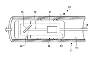
- FIG. 1 is a schematic view of a thinning state monitoring device for an inner surface of a heat transfer tube or an inner surface of an evaporation tube.
- FIG. 2 is another schematic view of a thinning state monitoring device for the inner surface of the heat transfer tube or the inner surface of the evaporation tube.
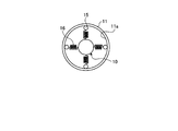
- FIG. 3 is another schematic diagram of a thinning state monitoring device for the inner surface of the heat transfer tube or the inner surface of the evaporation tube. 4 is a cross-sectional view of FIG.
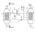
- FIG. 5 is a schematic view of a heat exchanger of an exhaust gas treatment facility.
- FIG. 1 is a schematic view of a thinning state monitoring device for an inner surface of a heat transfer tube or an inner surface of an evaporation tube.
- the thinning state monitoring device 10 on the inner surface of the heat transfer tube or the inner surface of the evaporation tube is a monitoring device that monitors the thinning state of the inner surface of the heat transfer tube or the inner surface of the evaporation tube.
- a moving means 12 that moves along the fin tube 11, a laser measuring means 13 that is provided in the moving means 12 and that measures the thinning state of the surface of the heat transfer tube or the evaporation tube, and a laser is provided to the laser measuring means 13.
- the cable means 14 having a light guide path for introducing light and a lead-out path for transmitting reflected light, and the data of the laser measuring means 13 are compared with past data or standard data to determine the current thinning state.
- a meat state judging means denotes a moving wheel.
- FIG. 5 is a schematic view of a heat exchanger of an exhaust gas treatment facility.
- a heat exchanger that introduces exhaust gas 80 and exchanges heat with the heat medium 83 is provided.
- the heat exchanger has a heat medium circulation passage 84 through which the heat medium 83 circulates between the heat recovery unit 81 and the reheater 82.
- the heat medium 83 circulates between the heat recovery device 81 and the reheater 82 via the heat medium circulation passage 84.
- a plurality of fins are provided in the fin tube 11 on the surface of the heat medium circulation passage 84 provided in each of the heat recovery device 81 and the reheater 82.
- a heat exchanging portion 86 is provided in the heat medium circulation passage 84, and the medium temperature of the heat medium 83 can be adjusted by exchanging the heat medium 83 with the steam 87.
- the heat medium 83 is supplied from the heat medium tank 88 to the heat medium circulation passage 84.
- the heat medium 83 is circulated in the heat medium circulation passage 84 by the heat medium feed pump 89. Further, the supply amount of the steam 87 is adjusted by the control valve V1 according to the gas temperature of the purified gas 91, and is sent to the reheater 82 by the control valve V2 according to the gas temperature of the exhaust gas 80 discharged from the heat recovery device 81.
- the supplied heat medium 83 is supplied to the heat recovery unit 81, and the supply amount of the heat medium 83 supplied to the reheater 82 is adjusted.
- the purified gas 91 discharged from the reheater 82 is discharged from the chimney 92 to the outside.
- the thinning state of the inner surface 11a of the fin tube 11 is monitored by the thinning state monitoring device 10 on the inner surface of the heat transfer tube or the evaporation tube.
- the laser measuring unit 13 calculates the focal length of the laser head 32 and the sensor head 31 having the laser displacement sensor.
- a shortening prism 33 is provided, and the laser beam 32 generated by the laser displacement sensor is passed through the prism 33 to shorten the focal length.
- FIG. 2 is another schematic view of a thinning state monitoring device for the inner surface of the heat transfer tube or the inner surface of the evaporation tube.
- a mirror 35 may be used instead of the prism 33 in the thinning state monitoring device 10 on the inner surface of the heat transfer tube or the inner surface of the evaporation tube.
- the laser beam 32 emitted from the laser displacement sensor is guided to the inner surface 11a of the fin tube 11 and is emitted perpendicularly to the surface of the fin tube 11 at the front end of the light guide path.
- tip part of a light guide way is controlled by the control means which is not shown in figure, and the reflective surface of the laser beam 32 is moved to the surrounding wall surface of the fin tube 11 360 degree
- the thickness of the thinned state is measured by continuously reading the position of the reflection surface from the tube wall of the fin tube 11 with the laser displacement sensor.
- the measurement data of the laser measurement means 13 is compared with past data or standard data, and the current thinning state is determined by the thinning state determination means. At this time, by recording position information from the measurement reference point, it is recorded together with the surface information from the laser displacement sensor in the information processing apparatus of the monitoring operator and displayed on the screen.
- the thinning state determination means receives plant / inspection site information from the plant information database. For example, the name of the plant to be inspected, the name of the site to be inspected, design data (the design outer diameter of the pipe, the design required wall thickness, the material, etc. ), Past inspection history, similar plant data, etc. are input.
- the laser measurement means 13 is moved while sequentially measuring the entire circumference of the inner surface 11a of the fin tube 11 by the movement of the movement means 12, and measures the thinned state.
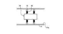
- FIG. 3 is another schematic view of a thinning state monitoring device for the inner surface of the heat transfer tube or the inner surface of the evaporation tube.
- FIG. 4 is a sectional view thereof. As shown in FIGS. 3 and 4, in the thinning state monitoring device 10 on the inner surface of the heat transfer tube or the inner surface of the evaporation tube, by providing the moving wheel 15 via the spring 16, when the fin tube 11 is bent, The spring 16 or the like is used so as to be in close contact with the inner wall surface.
- the thinning state monitoring device for the inner surface of the heat transfer tube or the inner surface of the evaporation tube it is possible to grasp the acquisition of the change in the surface position related to the thinning due to the wear of the inner surface of the pipe.
Landscapes
- Physics & Mathematics (AREA)
- General Physics & Mathematics (AREA)
- Engineering & Computer Science (AREA)
- High Energy & Nuclear Physics (AREA)
- Thermal Sciences (AREA)
- Mechanical Engineering (AREA)
- General Engineering & Computer Science (AREA)
- Length Measuring Devices By Optical Means (AREA)
Priority Applications (2)
| Application Number | Priority Date | Filing Date | Title |
|---|---|---|---|
| US13/877,135 US8743379B2 (en) | 2010-10-04 | 2011-09-29 | Device for monitoring thickness reduction of inner surface in heat transfer tube or inner surface in evaporation tube |
| EP11830544.0A EP2626624A4 (en) | 2010-10-04 | 2011-09-29 | DEVICE FOR THIN REDUCING THE INTERIOR IN A HEAT TRANSFER TUBE OR THE INTERIOR IN AN EVAPORATIVE TUBE |
Applications Claiming Priority (2)
| Application Number | Priority Date | Filing Date | Title |
|---|---|---|---|
| JP2010-225272 | 2010-10-04 | ||
| JP2010225272A JP5972527B2 (ja) | 2010-10-04 | 2010-10-04 | 伝熱管内面又は蒸発管内面の減肉状態監視装置 |
Publications (1)
| Publication Number | Publication Date |
|---|---|
| WO2012046611A1 true WO2012046611A1 (ja) | 2012-04-12 |
Family
ID=45927606
Family Applications (1)
| Application Number | Title | Priority Date | Filing Date |
|---|---|---|---|
| PCT/JP2011/072319 Ceased WO2012046611A1 (ja) | 2010-10-04 | 2011-09-29 | 伝熱管内面又は蒸発管内面の減肉状態監視装置 |
Country Status (4)
| Country | Link |
|---|---|
| US (1) | US8743379B2 (enExample) |
| EP (1) | EP2626624A4 (enExample) |
| JP (1) | JP5972527B2 (enExample) |
| WO (1) | WO2012046611A1 (enExample) |
Cited By (4)
| Publication number | Priority date | Publication date | Assignee | Title |
|---|---|---|---|---|
| CN103644853A (zh) * | 2013-12-16 | 2014-03-19 | 中国石油大学(北京) | 一种智能清管器的附属装置 |
| KR101945508B1 (ko) * | 2017-07-27 | 2019-02-08 | 한국광기술원 | 레이저를 이용한 배관 내부 검사장치 |
| CN110094714A (zh) * | 2019-04-09 | 2019-08-06 | 华电电力科学研究院有限公司 | 一种便于拆卸的电厂锅炉用冷却装置及其工作方法 |
| CN112082504A (zh) * | 2020-09-13 | 2020-12-15 | 中北大学 | 基于线结构光检测法的深孔内壁几何结构检测机器人系统 |
Families Citing this family (4)
| Publication number | Priority date | Publication date | Assignee | Title |
|---|---|---|---|---|
| US20160231555A1 (en) * | 2015-02-09 | 2016-08-11 | Visicon Technologies, Inc. | Borescope Inspection System |
| CN111562589A (zh) * | 2020-04-20 | 2020-08-21 | 国网浙江省电力有限公司电力科学研究院 | 一种电站锅炉水冷壁结渣程度的监视方法 |
| WO2024178101A1 (en) * | 2023-02-22 | 2024-08-29 | Kai Systems | Internal tube fouling sensors, systems, and methods |
| CN116753853B (zh) * | 2023-08-21 | 2023-11-17 | 昆明学院 | 一种电线表皮绝缘层检测设备及方法 |
Citations (7)
| Publication number | Priority date | Publication date | Assignee | Title |
|---|---|---|---|---|
| JPS6355441A (ja) * | 1986-08-26 | 1988-03-09 | Mitsubishi Electric Corp | 管内面形状検出装置 |
| JPS6438649A (en) | 1987-08-03 | 1989-02-08 | Hitachi Ltd | Ultrasonic probe for piping |
| JPH04264256A (ja) | 1991-02-19 | 1992-09-21 | Tokyo Gas Co Ltd | 配管探傷センサ |
| JPH0729405U (ja) * | 1993-11-01 | 1995-06-02 | 三菱重工業株式会社 | 管内面検査装置 |
| JPH07286828A (ja) * | 1994-04-19 | 1995-10-31 | Kobe Steel Ltd | 管内検査装置 |
| JPH0894325A (ja) * | 1994-09-29 | 1996-04-12 | Babcock Hitachi Kk | 伝熱管の管肉厚計測装置 |
| JP2005181139A (ja) | 2003-12-19 | 2005-07-07 | Jfe Engineering Kk | 管内検査方法および管内検査装置 |
Family Cites Families (19)
| Publication number | Priority date | Publication date | Assignee | Title |
|---|---|---|---|---|
| US4199258A (en) * | 1978-04-14 | 1980-04-22 | Electric Power Research Institute, Inc. | Distance measuring device and method |
| US4798002A (en) * | 1987-10-06 | 1989-01-17 | The United States Of America As Represented By The United States Department Of Energy | Wall thickness measuring method and apparatus |
| FR2631697B1 (fr) * | 1988-05-17 | 1991-07-26 | Hispano Suiza Sa | Appareil pour le controle optique du profil interne d'un tube ou d'un alesage |
| JPH0257974A (ja) * | 1988-08-24 | 1990-02-27 | Chiyoda Corp | 管内走行装置 |
| JP2533694B2 (ja) * | 1991-03-08 | 1996-09-11 | 日本電信電話株式会社 | 光ビ―ム走査型距離測定方法 |
| US5362962A (en) * | 1993-04-16 | 1994-11-08 | Edison Welding Institute | Method and apparatus for measuring pipeline corrosion |
| WO1995003526A1 (en) * | 1993-07-20 | 1995-02-02 | Commonwealth Scientific And Industrial Research Organisation | An inspection system for a conduit |
| JPH0743119A (ja) * | 1993-07-27 | 1995-02-10 | Nkk Corp | 管体の寸法測定装置 |
| DE4415582C2 (de) * | 1994-05-04 | 1997-03-06 | Autec Gmbh | Optische Abstandsmeßvorrichtung zur Abstandsmessung in Hohlräumen |
| JPH08178627A (ja) * | 1994-12-26 | 1996-07-12 | Sumitomo Wiring Syst Ltd | 管厚検査方法 |
| JPH10332646A (ja) | 1997-06-04 | 1998-12-18 | Ishikawajima Harima Heavy Ind Co Ltd | スパイラルフィンチューブのフィン溶接部の超音波探傷検査装置 |
| AU2001269717A1 (en) * | 2000-05-30 | 2001-12-11 | Oyo Corp. U.S.A. | Apparatus and method for detecting pipeline defects |
| US6931149B2 (en) * | 2002-04-19 | 2005-08-16 | Norsk Elektro Optikk A/S | Pipeline internal inspection device and method |
| EP1681531B1 (de) * | 2005-01-13 | 2008-04-23 | Plast-Control GmbH | Vorrichtung und Verfahren zur kapazitiven Vermessung von Materialien |
| DE102005059550A1 (de) * | 2005-12-13 | 2007-06-14 | Siemens Ag | Optische Messvorrichtung zum Vermessen eines Hohlraums |
| DE202006017076U1 (de) * | 2006-11-08 | 2007-01-04 | Fraunhofer-Gesellschaft zur Förderung der angewandten Forschung e.V. | Vorrichtung zur Inspektion einer Rohrleitung |
| CA2568021A1 (fr) * | 2006-11-20 | 2008-05-20 | Colmatec Inc. | Dispositif pour mesurer des fissures dans des conduites |
| JP5129727B2 (ja) | 2008-01-31 | 2013-01-30 | 三菱重工業株式会社 | ボイラ火炉蒸発管の検査装置および検査方法 |
| NO333307B1 (no) * | 2008-11-24 | 2013-04-29 | Statoil Asa | Anordning og fremgangsmate for optisk maling av tykkelsen av enhver avsetning av materiale pa innerveggen til en konstruksjon |
-
2010
- 2010-10-04 JP JP2010225272A patent/JP5972527B2/ja not_active Expired - Fee Related
-
2011
- 2011-09-29 WO PCT/JP2011/072319 patent/WO2012046611A1/ja not_active Ceased
- 2011-09-29 EP EP11830544.0A patent/EP2626624A4/en not_active Withdrawn
- 2011-09-29 US US13/877,135 patent/US8743379B2/en not_active Expired - Fee Related
Patent Citations (7)
| Publication number | Priority date | Publication date | Assignee | Title |
|---|---|---|---|---|
| JPS6355441A (ja) * | 1986-08-26 | 1988-03-09 | Mitsubishi Electric Corp | 管内面形状検出装置 |
| JPS6438649A (en) | 1987-08-03 | 1989-02-08 | Hitachi Ltd | Ultrasonic probe for piping |
| JPH04264256A (ja) | 1991-02-19 | 1992-09-21 | Tokyo Gas Co Ltd | 配管探傷センサ |
| JPH0729405U (ja) * | 1993-11-01 | 1995-06-02 | 三菱重工業株式会社 | 管内面検査装置 |
| JPH07286828A (ja) * | 1994-04-19 | 1995-10-31 | Kobe Steel Ltd | 管内検査装置 |
| JPH0894325A (ja) * | 1994-09-29 | 1996-04-12 | Babcock Hitachi Kk | 伝熱管の管肉厚計測装置 |
| JP2005181139A (ja) | 2003-12-19 | 2005-07-07 | Jfe Engineering Kk | 管内検査方法および管内検査装置 |
Non-Patent Citations (1)
| Title |
|---|
| See also references of EP2626624A4 * |
Cited By (7)
| Publication number | Priority date | Publication date | Assignee | Title |
|---|---|---|---|---|
| CN103644853A (zh) * | 2013-12-16 | 2014-03-19 | 中国石油大学(北京) | 一种智能清管器的附属装置 |
| CN103644853B (zh) * | 2013-12-16 | 2015-12-02 | 中国石油大学(北京) | 一种智能清管器的附属装置 |
| KR101945508B1 (ko) * | 2017-07-27 | 2019-02-08 | 한국광기술원 | 레이저를 이용한 배관 내부 검사장치 |
| CN110094714A (zh) * | 2019-04-09 | 2019-08-06 | 华电电力科学研究院有限公司 | 一种便于拆卸的电厂锅炉用冷却装置及其工作方法 |
| CN110094714B (zh) * | 2019-04-09 | 2023-11-28 | 华电电力科学研究院有限公司 | 一种便于拆卸的电厂锅炉用冷却装置及其工作方法 |
| CN112082504A (zh) * | 2020-09-13 | 2020-12-15 | 中北大学 | 基于线结构光检测法的深孔内壁几何结构检测机器人系统 |
| CN112082504B (zh) * | 2020-09-13 | 2022-04-01 | 中北大学 | 基于线结构光检测法的深孔内壁几何结构检测机器人系统 |
Also Published As
| Publication number | Publication date |
|---|---|
| US8743379B2 (en) | 2014-06-03 |
| EP2626624A1 (en) | 2013-08-14 |
| JP2012078037A (ja) | 2012-04-19 |
| US20130182265A1 (en) | 2013-07-18 |
| EP2626624A4 (en) | 2016-12-21 |
| JP5972527B2 (ja) | 2016-08-17 |
Similar Documents
| Publication | Publication Date | Title |
|---|---|---|
| JP5972527B2 (ja) | 伝熱管内面又は蒸発管内面の減肉状態監視装置 | |
| JP6223342B2 (ja) | ガスタービンを検査するための内視鏡検査システムおよび対応する方法 | |
| KR101629538B1 (ko) | 원자력 발전소의 증기 발생기 튜브의 현재 상태를 비파괴적으로 평가하는 방법 | |
| US20130003048A1 (en) | Fouling detection setup and method to detect fouling | |
| EP2486397A1 (en) | Method for inspecting corrosion under insulation | |
| US20070006656A1 (en) | System and method for monitoring deposition within tubes of a heating system | |
| JP2018084516A (ja) | 溶接機能付き管内形状測定装置、及び小内径管用の管内形状測定装置 | |
| US10048225B2 (en) | Apparatus and method for inspection of tubes in a boiler | |
| CN100405057C (zh) | 龟裂的非破坏定量评价方法 | |
| US12152998B2 (en) | Erosion detection and prediction | |
| US9625421B2 (en) | Manually operated small envelope scanner system | |
| JP4363699B2 (ja) | 浸炭層の検出方法及びその厚さの測定方法 | |
| JP2012078262A (ja) | 伝熱管又は蒸発管の減肉状態監視装置 | |
| JP2006138784A (ja) | 渦電流探傷プローブおよび渦電流探傷システム | |
| JP2024007341A (ja) | 回転構成要素に放射線を伝送する装置及び方法 | |
| JP2010117160A (ja) | フィンチューブの欠陥検査装置 | |
| KR20220042220A (ko) | 관 부재의 검사 시스템 및 관 부재의 검사 방법 | |
| US20130088707A1 (en) | Method and system for crack detection | |
| KR20220057330A (ko) | 배열회수보일러 핀 튜브 검사 장치 | |
| Bykov et al. | Application of acoustic pulse reflectometry in nondestructive testing of heat exchanger pipes | |
| Beller et al. | Multi-diameter and quantitative inspection technologies for offshore pipelines | |
| JP2010060476A (ja) | 配管の検査方法 | |
| Vivekanand et al. | Nde techniques for reliable inspection of carbon steel tubes | |
| US20240280207A1 (en) | Internal tube fouling sensors, systems, and methods | |
| Madan et al. | Fiber Bragg grating sensors for real-time monitoring of boiler U-bend tubes thinning |
Legal Events
| Date | Code | Title | Description |
|---|---|---|---|
| 121 | Ep: the epo has been informed by wipo that ep was designated in this application |
Ref document number: 11830544 Country of ref document: EP Kind code of ref document: A1 |
|
| WWE | Wipo information: entry into national phase |
Ref document number: 2011830544 Country of ref document: EP |
|
| WWE | Wipo information: entry into national phase |
Ref document number: 13877135 Country of ref document: US |
|
| NENP | Non-entry into the national phase |
Ref country code: DE |