WO2012046465A1 - モータの回転子及びその回転子の製造方法 - Google Patents
モータの回転子及びその回転子の製造方法 Download PDFInfo
- Publication number
- WO2012046465A1 WO2012046465A1 PCT/JP2011/055749 JP2011055749W WO2012046465A1 WO 2012046465 A1 WO2012046465 A1 WO 2012046465A1 JP 2011055749 W JP2011055749 W JP 2011055749W WO 2012046465 A1 WO2012046465 A1 WO 2012046465A1
- Authority
- WO
- WIPO (PCT)
- Prior art keywords
- permanent magnet
- rotor
- magnet
- insertion hole
- magnet insertion
- Prior art date
- Legal status (The legal status is an assumption and is not a legal conclusion. Google has not performed a legal analysis and makes no representation as to the accuracy of the status listed.)
- Ceased
Links
Images



Classifications
-
- H—ELECTRICITY
- H02—GENERATION; CONVERSION OR DISTRIBUTION OF ELECTRIC POWER
- H02K—DYNAMO-ELECTRIC MACHINES
- H02K1/00—Details of the magnetic circuit
- H02K1/06—Details of the magnetic circuit characterised by the shape, form or construction
- H02K1/22—Rotating parts of the magnetic circuit
- H02K1/27—Rotor cores with permanent magnets
- H02K1/2706—Inner rotors
- H02K1/272—Inner rotors the magnetisation axis of the magnets being perpendicular to the rotor axis
- H02K1/274—Inner rotors the magnetisation axis of the magnets being perpendicular to the rotor axis the rotor consisting of two or more circumferentially positioned magnets
- H02K1/2753—Inner rotors the magnetisation axis of the magnets being perpendicular to the rotor axis the rotor consisting of two or more circumferentially positioned magnets the rotor consisting of magnets or groups of magnets arranged with alternating polarity
- H02K1/276—Magnets embedded in the magnetic core, e.g. interior permanent magnets [IPM]
-
- H—ELECTRICITY
- H02—GENERATION; CONVERSION OR DISTRIBUTION OF ELECTRIC POWER
- H02K—DYNAMO-ELECTRIC MACHINES
- H02K15/00—Processes or apparatus specially adapted for manufacturing, assembling, maintaining or repairing of dynamo-electric machines
- H02K15/02—Processes or apparatus specially adapted for manufacturing, assembling, maintaining or repairing of dynamo-electric machines of stator or rotor bodies
- H02K15/03—Processes or apparatus specially adapted for manufacturing, assembling, maintaining or repairing of dynamo-electric machines of stator or rotor bodies having permanent magnets
Definitions
- the present invention is a cylindrical rotor body, a plurality of magnet insertion holes that are arranged at equal intervals in the circumferential direction of the rotor body, and are formed to extend in the axial direction of the rotor body,
- the present invention relates to a rotor of a motor having a plurality of permanent magnets respectively housed in the magnet insertion holes and a method for manufacturing the rotor.
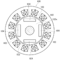
- the rotor 102 of the motor 100 described in Patent Document 1 includes a cylindrical rotor body 102m, and is formed in a square plate shape near the outer peripheral surface of the rotor body 102m.
- the four permanent magnets 104 are embedded at equal intervals in the circumferential direction.
- the permanent magnet 104 is inserted into each magnet insertion hole 103 formed in the rotor body 102m, It is embedded in the rotor body 102m.
- the surface of the permanent magnet 104 is covered with the insulating layer made of an oxide film, eddy current flowing through the permanent magnet 104 can be reduced, and heat generation of the permanent magnet 104 can be suppressed.
- the permanent magnet 104 is inserted into the magnet insertion hole 103 of the rotor body 102m. For this reason, when the permanent magnet 104 is inserted into the magnet insertion hole 103, the insulating layer on the surface may be damaged and the insulating property may be lowered. In order to prevent the insulating layer from being damaged, it is conceivable to set a large clearance between the permanent magnet 104 and the magnet insertion hole 103. In this case, the permanent magnet 104 and the magnet are inserted when the motor 100 is driven. Vibration may occur between the holes 103.
- the present invention has been made to solve the above-mentioned problems, and the problem to be solved by the present invention is to prevent vibration between the magnet insertion hole of the rotor body and the permanent magnet, and It is to prevent the insulating layer on the surface of the magnet from being damaged.
- the invention according to claim 1 is a cylindrical rotor main body, and a plurality of magnet insertions arranged at equal intervals in the circumferential direction of the rotor main body and extending in the axial direction of the rotor main body.
- a rotor of a motor having a hole and a plurality of permanent magnets respectively inserted into the magnet insertion holes, wherein the magnet insertion hole is configured such that the permanent magnet is inserted through a gap. Further, on the inner wall surface of the magnet insertion hole, when the permanent magnet is inserted into the magnet insertion hole, the permanent magnet is prevented from being displaced in a direction perpendicular to the axial direction of the rotor body.
- a plurality of protrusions for restraining the inner surface of the magnet, and the gap between the inner wall surface of the magnet insertion hole and the permanent magnet is formed by electrodeposition coating the rotor body after the permanent magnet is inserted. That it is blocked by And butterflies.
- the magnet insertion hole of the rotor main body is formed larger than the permanent magnet so that a gap or the like is formed between the inner wall surface of the magnet insertion hole and the permanent magnet.
- a gap or the like is formed between the inner wall surface of the magnet insertion hole and the permanent magnet.
- the surface of the permanent magnet is covered with the insulating coating film. For this reason, the insulating layer (coating film) covering the surface of the permanent magnet is not damaged. Further, since the gap between the magnet insertion hole of the rotor body and the permanent magnet is closed by the coating film, vibration hardly occurs between the magnet insertion hole and the permanent magnet when the motor is driven.
- the permanent magnet is formed in a square plate shape, and the inner wall surface of the magnet insertion hole is configured to sandwich the permanent magnet from the thickness direction with a gap interposed therebetween.
- the projection is formed on the thickness direction restraint surface so that the permanent magnet can be restrained from both sides in the width direction and guided in the axial direction of the rotor body. It is characterized by being. That is, since the permanent magnet is constrained by the protrusions from both sides in the width direction, the width dimension of the magnet insertion hole can be made larger than the width dimension of the permanent magnet, and a wide space can be formed at both sides in the width direction of the permanent magnet.
- the permanent magnet is formed in a square plate shape, and the inner wall surface of the magnet insertion hole is configured to sandwich the permanent magnet from the thickness direction through the gap.
- a pair of thickness direction constraining surfaces, and the protrusions are formed on the thickness direction constraining surfaces on both sides, and the gap retaining projections that maintain the gap between the thickness direction constraining surfaces and the permanent magnets at a constant dimension;
- the permanent magnet is constrained from both sides in the width direction, and the permanent magnet is constituted by a guide projection having a guide surface formed so as to be able to guide the permanent magnet in the axial direction of the rotor body.
- the permanent magnet since the permanent magnet is constrained from both sides in the width direction by the guide projection, a wide space can be formed at both sides in the width direction of the permanent magnet as described above. Furthermore, the gap between the thickness direction constraining surface and the permanent magnet can be held at a constant size by the gap holding projection. For this reason, the thickness dimension of the coating film by electrodeposition coating can be made substantially constant.
- a cylindrical rotor body and a plurality of magnet inserts arranged at equal intervals in the circumferential direction of the rotor body and extending in the axial direction of the rotor body.
- the permanent magnet material Forming on the inner wall surface of the magnet insertion hole; inserting the permanent magnet material into the magnet insertion hole; and electrodeposition-coating the rotor body into which the permanent magnet material is inserted;
- the inner wall surface of the insertion hole and the element of the permanent magnet A step of closing the gap between in the coating of insulating, after the electrodeposition coating step, characterized by a step of magnetizing the material of the permanent magnet. According to the present invention, the same effect as that of the invention according to claim 1 can be obtained.
- the permanent magnet material is magnetized after the permanent magnet material is inserted into the magnet insertion hole, the permanent magnet material can be easily inserted into the magnet insertion hole.
- a cylindrical rotor main body and a plurality of magnets inserted so as to extend in the axial direction of the rotor main body are arranged at equal intervals in the circumferential direction of the rotor main body.
- the present invention it is possible to prevent the insulating layer covering the surface of the permanent magnet from being damaged, and to suppress vibration between the magnet insertion hole of the rotor body and the permanent magnet when the motor is driven.
- FIG. 5 is a cross-sectional view taken along the line V-V in FIG. 4.
- FIG. 6 is an enlarged view of a VI part in FIG. 5.
- It is a top view of the magnet insertion hole of the rotor main body which concerns on the example of a change.
- It is a flowchart showing the manufacturing method of the rotor of the motor which concerns on Embodiment 1 of this invention.
- It is a schematic cross section orthogonal to the shaft center of a motor provided with the conventional rotor.
- Embodiment 1 A motor rotor and a method of manufacturing the rotor will be described below in Embodiment 1 of the present invention with reference to FIGS. Note that the X direction, the Y direction, and the Z direction shown in the figure correspond to the horizontal direction, vertical (height) direction, and axial direction of the motor.
- the motor 10 is an embedded magnet type motor, and a permanent magnet 30 is embedded in a rotor body 22 of the rotor 20 as shown in FIG.
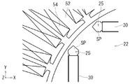
- the stator 50 of the motor 10 is formed in a substantially cylindrical shape, and, for example, 24 armature cores 52 are formed on the inner peripheral surface of the stator 50 at equal intervals in the circumferential direction.
- An armature winding 54 is wound around each armature core 52.
- the armature winding 54 is configured to generate a rotating magnetic field that rotates about the axis of the stator 50 when an alternating current is passed.
- the rotating magnetic field generated by the armature winding 54 pulls the permanent magnet 30 of the rotor body 22, so that the rotor 20 rotates in synchronization with the rotating magnetic field.
- the rotor 20 includes a rotor body 22 and a rotation center shaft 24 that are provided coaxially, and one end side and the other end side of the rotation center shaft 24 are fixed to the stator 50. It is supported by a bearing (not shown). As a result, the rotor 20 is accommodated in the stator 50 while being held coaxially with the stator 50.
- the rotor body 22 of the rotor 20 is formed in a cylindrical shape as shown in FIG. 3 by laminating insulated steel plates 22p in the axial direction. As shown in FIG.
- a magnet insertion hole 25 formed in a flat hexagonal slit shape is formed in the rotor body 22 so as to extend in the axial direction from one end side to the other end side of the rotor body 22. ing.
- Four magnet insertion holes 25 are formed at equal intervals in the circumferential direction of the rotor body 22.
- the magnet insertion holes 25 are positioned so as to form square sides inscribed in a virtual circle overlapping the outer peripheral surface of the rotor body 22 as shown in FIGS. 1 and 3.
- the four magnet insertion holes 25 are composed of two sets of magnet insertion holes 25 arranged so as to face each other with the center of the rotor body 22 in between, and one set of magnet insertion holes 25 and the other set of The magnet insertion hole 25 is arranged with a phase shifted by 90 °.
- the permanent magnet 30 is inserted into the magnet insertion hole 25 of the rotor body 22 as shown in FIGS.
- the permanent magnet 30 is formed in a square plate shape, and magnetic poles are provided on the front surface side and the back surface side (see FIG. 3).
- the length dimension of the permanent magnet 30 (the length dimension in the axial direction of the rotor body 22) is set to the length dimension L of the magnet insertion hole 25 (the axis length dimension of the rotor body 22). It is set to almost the same value.
- a pair of thickness direction restraining surfaces 25 k configured to sandwich the permanent magnet 30 from the thickness direction is formed in the magnet insertion hole 25 of the rotor body 22.
- V-shaped end surfaces 25v each having a V-groove shape for expanding the magnet insertion hole 25 outward in the width direction are formed at positions on both sides in the width direction (left and right sides in FIG. 4) of the thickness direction restraining surface 25k.
- Each of the thickness direction restraining surfaces 25k is formed with a rail-like protrusion 26 extending in the insertion direction of the permanent magnet 30, that is, in the axial direction of the rotor body 22, in the vicinity of the left and right V-shaped end surfaces 25v. Yes.
- the ridge 26 is for positioning the permanent magnet 30 in the center of the magnet insertion hole 25 in the width direction, and is formed in a semi-elliptical cross section, and the ridge 26 on one thickness direction restraining surface 25k and the other thickness. It is formed in the position (position which overlaps in the width direction) where the protrusion 26 of the direction restraint surface 25k opposes. Further, the distance between the left ridge 26 and the right ridge 26 is set to a dimension substantially equal to the width dimension W1 of the permanent magnet 30 as shown in FIG.
- the distance T0 between the one thickness direction restraint surface 25k and the other thickness direction restraint surface 25k is a state in which the permanent magnet 30 is inserted into the magnet insertion hole 25.
- the values are set such that gaps SL (30 ⁇ m to 40 ⁇ m) each having a predetermined dimension are formed between the thickness direction restraining surfaces 25k on both sides and the permanent magnet 30. That is, the slit width dimension T0 of the magnet insertion hole 25 is set to a value that is about a gap (SL ⁇ 2) larger than the thickness dimension T1 of the permanent magnet 30.
- the corners of the four corners of the permanent magnet 30 come into contact with the inclined side surfaces of the protrusion 26 having a semi-elliptical cross section. For this reason, as shown in FIGS. 4 and 5, a gap SL having a predetermined dimension is formed on both sides in the thickness direction of the permanent magnet 30 in a state where the permanent magnet 30 is inserted into the magnet insertion hole 25 using the protrusions 26 at the four corners. Are formed, and a substantially pentagonal space SP is formed on both sides of the permanent magnet 30 in the width direction. That is, the protrusion 26 corresponds to the protrusion of the present invention.
- the rotor body 22 is electrodeposited with the permanent magnets 30 inserted into the respective magnet insertion holes 25.
- the electrodeposition coating is a method in which an object to be coated (rotor body 22) is immersed in a water-soluble electrodeposition paint to serve as a cathode, and a direct current is passed from the anode to the cathode in the electrodeposition paint.
- the object to be coated is applied. That is, in the vicinity of the cathode (rotor body 22), the paint undergoes a chemical reaction to become an insoluble resin (insulating material), and a coating film R is formed on the surface of the rotor body 22, and the rotor body 22 As a result, the resin penetrates into the gaps, and an insulating coating film R is formed.
- both end surfaces 32 in the length direction of the permanent magnet 30 positioned on the surface of the rotor body 22 are covered with the coating film R as shown in FIG. 6, and the permanent magnet 30 and the magnet insertion hole in FIG. 25 gaps SL are blocked by the coating film R (see FIG. 6).
- the inner peripheral surface of the substantially pentagonal space SP of the magnet insertion hole 25 and the width direction both end surfaces 34 (see FIG. 4) of the permanent magnet 30 constituting the inner peripheral surface are covered with the coating film R. . That is, the surface of the permanent magnet 30 is entirely covered with the coating film R.
- the surface of the permanent magnet 30 is covered with the insulating coating film R, eddy current flowing through the permanent magnet 30 can be reduced, and heat generation of the permanent magnet 30 can be suppressed.
- the coating film R penetrates into that portion. Become.
- the iron core portion of the rotor 20 and the iron core portion of the stator 50 are manufactured in separate steps (steps S101 and S102).
- the material of the permanent magnet 30 is inserted into the magnet insertion hole 25 formed in the rotor body 22 of the rotor 20 (step S103).
- the material of the permanent magnet 30 is restrained from both sides in the width direction by the ridges 26 formed in the magnet insertion holes 25, and the material of the permanent magnet 30 is magnetized along the ridges 26. Insert into the insertion hole 25.
- the material of the permanent magnet 30 is electrically connected to the rotor body 22 via the protrusions 26 in a state where the material of the permanent magnet 30 is inserted into the magnet insertion hole 25.
- both 20 and 50 are immersed in a water-soluble electrodeposition paint to perform electrodeposition coating ( Step S104).
- the surface of the iron core portion of the stator 50, the surface of the iron core portion of the rotor 20, and the surface of the permanent magnet 30 are covered with the insulating coating R, and as described above, the permanent magnet 30 and the magnet.
- the gap SL or the like of the insertion hole 25 is blocked by the coating film R.
- a magnetic field is applied to the material of the permanent magnets 30 of the rotor 20 from the outside to magnetize the materials of the permanent magnets 30 (step S105).
- the material functions as the permanent magnet 30.
- the armature winding 54 is wound around the armature core 52 of the stator 50 in parallel with the magnetization of the material of the permanent magnet 30 (step S106). In this way, with the rotor 20 and the stator 50 being manufactured, the rotor 20 is assembled to the stator 50, and the motor 10 is completed (step S107).
- the magnet insertion hole 25 of the rotor body 22 has a permanent magnet 30 such that a gap SL or the like is formed between the inner wall surface (thickness direction constraining surface 25 k) of the magnet insertion hole 25 and the permanent magnet 30. It is greatly formed. However, since a plurality of protrusions (protrusions 26) are formed on the thickness direction restraining surface 25k of the magnet insertion hole 25, when the permanent magnet 30 is inserted into the magnet insertion hole 25, it is perpendicular to the insertion direction.
- the permanent magnet 30 can be disposed at a fixed position in the magnet insertion hole 25 without being displaced in the direction.
- the gap SL between the thickness direction restraining surface 25k of the magnet insertion hole 25 and the permanent magnet 30 is blocked by an insulating coating R formed by electrodeposition coating. That is, after the permanent magnet 30 is inserted into the magnet insertion hole 25 of the rotor body 22, the surface of the permanent magnet 30 is covered with the insulating coating film R. For this reason, the insulating layer (coating film) on the surface of the permanent magnet 30 is not damaged. Further, since the gap SL between the magnet insertion hole 25 of the rotor main body 22 and the permanent magnet 30 is closed by the coating film R, vibration is hardly generated between the magnet insertion hole 25 and the permanent magnet 30 when the motor 10 is driven. .
- the width dimension of the magnet insertion hole 25 is made larger than the width dimension of the permanent magnet 30 and is wide at both positions in the width direction of the permanent magnet 30.
- a space SP can be formed. This makes it difficult for the magnetic flux to pass from the front side (for example, N pole) to the back side (for example, S pole) of the permanent magnet 30. That is, the magnetic flux of the permanent magnet 30 can be efficiently guided from the outer peripheral surface of the rotor body 22 to the stator 50 side.
- the material of the permanent magnet 30 is magnetized after the material of the permanent magnet 30 is inserted into the magnet insertion hole 25, the material of the permanent magnet 30 can be easily inserted into the magnet insertion hole 25.
- the present invention is not limited to the above-described embodiment, and modifications can be made without departing from the gist of the present invention.
- the magnet insertion hole 25 is formed in a flat hexagonal slit shape, and the protrusion 26 that restrains the permanent magnet 30 from both sides in the width direction is formed on the thickness direction restraining surface 25 k of the magnet insertion hole 25.
- An example is shown.
- a gap holding protrusion 25 x for holding the gap SL with the permanent magnet 30 at a constant dimension is formed on the thickness direction restraining surface 25 k of the magnet insertion hole 25.
- the gap SL between the thickness direction restraining surface 25k of the magnet insertion hole 25 and the permanent magnet 30 can be held at a constant dimension by the gap holding projection 25x, so that the thickness dimension of the coating film by electrodeposition coating becomes substantially constant.
- the material of the permanent magnet 30 is inserted into the magnet insertion hole 25 of the rotor body 22 and then the magnetic field is applied to the rotor body 22 to magnetize the material of the permanent magnet 30.
- the gap SL can be maintained at a constant size even if the magnetized permanent magnet 30 is inserted into the magnet insertion hole 25.
Landscapes
- Engineering & Computer Science (AREA)
- Power Engineering (AREA)
- Manufacturing & Machinery (AREA)
- Permanent Field Magnets Of Synchronous Machinery (AREA)
- Manufacture Of Motors, Generators (AREA)
Abstract
本発明は、回転子本体の磁石挿入穴と永久磁石間で振動が発生しないようにするとともに、永久磁石の絶縁層に傷が付かないようにして渦電流を低減させる。 本発明は、回転子本体(22)と、回転子本体(22)の円周方向に等間隔で配置されて軸方向に延びるように形成された複数の磁石挿入穴(25)と、それらの磁石挿入穴(25)にそれぞれ挿入される永久磁石(30)とを有するモータの回転子であって、磁石挿入穴(25)は、永久磁石(30)が隙間(SL)を介した状態で挿入されるように構成されており、さらに磁石挿入穴(25)の内壁面には、永久磁石(30)がその磁石挿入穴(25)に挿入される際、幅方向に変位しないように、その永久磁石を幅方向から拘束する複数の突起(26)が設けられており、磁石挿入穴(25)の内壁面と永久磁石(30)との隙間(SL)が電着塗装により形成された絶縁性の塗膜によって塞がれている。これにより、永久磁石(30)に発生する渦電流を低減できる。
Description
本発明は、円柱形の回転子本体と、前記回転子本体の円周方向に等間隔で配置されており、その回転子本体の軸方向に延びるように形成された複数の磁石挿入穴と、それらの磁石挿入穴にそれぞれ収納される複数の永久磁石とを有するモータの回転子及びその回転子の製造方法に関する。
モータの回転子に関する技術が特許文献1に記載されている。
特許文献1に記載されたモータ100の回転子102は、図9に示すように、円柱形の回転子本体102mを備えており、その回転子本体102mの外周面近傍位置に角板状に形成された四枚の永久磁石104が円周方向に等間隔で埋め込まれている。
前記回転子102では、各々の永久磁石104の表面に酸化被膜からなる絶縁層を形成した後、それらの永久磁石104を回転子本体102mに形成された各々の磁石挿入穴103に挿入して、回転子本体102mに埋め込むようにしている。
このように、永久磁石104の表面が酸化被膜からなる絶縁層に覆われているため、永久磁石104を流れる渦電流を低減させることができ、前記永久磁石104の発熱を抑えることができる。
特許文献1に記載されたモータ100の回転子102は、図9に示すように、円柱形の回転子本体102mを備えており、その回転子本体102mの外周面近傍位置に角板状に形成された四枚の永久磁石104が円周方向に等間隔で埋め込まれている。
前記回転子102では、各々の永久磁石104の表面に酸化被膜からなる絶縁層を形成した後、それらの永久磁石104を回転子本体102mに形成された各々の磁石挿入穴103に挿入して、回転子本体102mに埋め込むようにしている。
このように、永久磁石104の表面が酸化被膜からなる絶縁層に覆われているため、永久磁石104を流れる渦電流を低減させることができ、前記永久磁石104の発熱を抑えることができる。
上記した回転子102では、永久磁石104の表面に絶縁層を形成した後、その永久磁石104を回転子本体102mの磁石挿入穴103に挿入する方法である。このため、永久磁石104を磁石挿入穴103に挿入する際に、表面の絶縁層に傷が付いて絶縁性が低下することがある。
また、前記絶縁層の傷付きを抑えるために、前記永久磁石104と磁石挿入穴103間のクリアランスを大きく設定することも考えられるが、このようにするとモータ100の駆動時に永久磁石104と磁石挿入穴103間で振動が発生することがある。
また、前記絶縁層の傷付きを抑えるために、前記永久磁石104と磁石挿入穴103間のクリアランスを大きく設定することも考えられるが、このようにするとモータ100の駆動時に永久磁石104と磁石挿入穴103間で振動が発生することがある。
本発明は、上記問題点を解決するためになされたものであり、本発明が解決しようとする課題は、回転子本体の磁石挿入穴と永久磁石間で振動が発生しないようにするとともに、永久磁石の表面の絶縁層に傷が付かないようにすることである。
上記した課題は、各請求項の発明によって解決される。
請求項1の発明は、円柱形の回転子本体と、前記回転子本体の円周方向に等間隔で配置されており、その回転子本体の軸方向に延びるように形成された複数の磁石挿入穴と、それらの磁石挿入穴にそれぞれ挿入される複数の永久磁石とを有するモータの回転子であって、前記磁石挿入穴は、前記永久磁石が隙間を介した状態で挿入されるように構成されており、さらに前記磁石挿入穴の内壁面には、前記永久磁石がその磁石挿入穴に挿入される際、前記回転子本体の軸方向に対して直角方向に変位しないように、その永久磁石を拘束する複数の突起が設けられており、前記磁石挿入穴の内壁面と前記永久磁石間の前記隙間が前記永久磁石挿入後の前記回転子本体を電着塗装することにより形成された絶縁性の塗膜によって塞がれていることを特徴とする。
請求項1の発明は、円柱形の回転子本体と、前記回転子本体の円周方向に等間隔で配置されており、その回転子本体の軸方向に延びるように形成された複数の磁石挿入穴と、それらの磁石挿入穴にそれぞれ挿入される複数の永久磁石とを有するモータの回転子であって、前記磁石挿入穴は、前記永久磁石が隙間を介した状態で挿入されるように構成されており、さらに前記磁石挿入穴の内壁面には、前記永久磁石がその磁石挿入穴に挿入される際、前記回転子本体の軸方向に対して直角方向に変位しないように、その永久磁石を拘束する複数の突起が設けられており、前記磁石挿入穴の内壁面と前記永久磁石間の前記隙間が前記永久磁石挿入後の前記回転子本体を電着塗装することにより形成された絶縁性の塗膜によって塞がれていることを特徴とする。
本発明によると、回転子本体の磁石挿入穴は、その磁石挿入穴の内壁面と永久磁石間に隙間等が形成されるように、前記永久磁石に対して大きく形成されている。しかし、磁石挿入穴の内壁面には複数の突起が形成されているため、永久磁石がその磁石挿入穴に挿入される際、挿入方向に対して直角方向に位置ずれすることがなく、その永久磁石を前記磁石挿入穴内の定位置に配置できるようになる。
さらに、磁石挿入穴の内壁面と永久磁石間の隙間は、永久磁石挿入後の回転子本体を電着塗装することにより形成された絶縁性の塗膜によって塞がれている。即ち、永久磁石が回転子本体の磁石挿入穴に挿入された後で、その永久磁石の表面が絶縁性の塗膜によって覆われるようになる。このため、永久磁石の表面を覆う絶縁層(塗膜)に傷が付かない。
さらに、回転子本体の磁石挿入穴と永久磁石間の隙間が塗膜によって塞がれるため、モータの駆動時に磁石挿入穴と永久磁石間で振動が発生し難くなる。
さらに、磁石挿入穴の内壁面と永久磁石間の隙間は、永久磁石挿入後の回転子本体を電着塗装することにより形成された絶縁性の塗膜によって塞がれている。即ち、永久磁石が回転子本体の磁石挿入穴に挿入された後で、その永久磁石の表面が絶縁性の塗膜によって覆われるようになる。このため、永久磁石の表面を覆う絶縁層(塗膜)に傷が付かない。
さらに、回転子本体の磁石挿入穴と永久磁石間の隙間が塗膜によって塞がれるため、モータの駆動時に磁石挿入穴と永久磁石間で振動が発生し難くなる。
請求項2の発明によると、永久磁石は角形の板状に形成されており、磁石挿入穴の内壁面は、隙間を介した状態で、前記永久磁石を厚み方向から挟めるように構成された一対の厚み方向拘束面を有しており、突起は、前記厚み方向拘束面に形成されて、前記永久磁石を幅方向両側から拘束し、前記回転子本体の軸方向にガイドできるように構成されていることを特徴とする。
即ち、永久磁石が突起によって幅方向両側から拘束されるため、磁石挿入穴の幅寸法を永久磁石の幅寸法よりも大きくして、その永久磁石の幅方向両側位置に広い空間を形成できる。これにより、永久磁石の表側(例えば、N極)から裏側(例えば、S極)に磁束が通り難くなる。即ち、前記永久磁石の磁束を効率的に回転子本体の外周面から固定子側に導けるようになる。
即ち、永久磁石が突起によって幅方向両側から拘束されるため、磁石挿入穴の幅寸法を永久磁石の幅寸法よりも大きくして、その永久磁石の幅方向両側位置に広い空間を形成できる。これにより、永久磁石の表側(例えば、N極)から裏側(例えば、S極)に磁束が通り難くなる。即ち、前記永久磁石の磁束を効率的に回転子本体の外周面から固定子側に導けるようになる。
請求項3の発明によると、永久磁石は角形の板状に形成されており、磁石挿入穴の内壁面は、前記隙間を介した状態で、前記永久磁石を厚み方向から挟めるように構成された一対の厚み方向拘束面を有しており、突起は、両側の厚み方向拘束面に形成されて、それらの厚み方向拘束面と前記永久磁石間の隙間を一定寸法に保持する隙間保持突起と、前記永久磁石を幅方向両側から拘束してその永久磁石を前記回転子本体の軸方向にガイド可能に形成されたガイド面を備えるガイド突起とから構成されていることを特徴とする。
即ち、永久磁石がガイド突起によって幅方向両側から拘束される構成のため、上記したように、永久磁石の幅方向両側位置に広い空間を形成できる。さらに、隙間保持突起により、厚み方向拘束面と永久磁石間の隙間を一定寸法に保持できる。このため、電着塗装による塗膜の厚み寸法をほぼ一定にできる。
即ち、永久磁石がガイド突起によって幅方向両側から拘束される構成のため、上記したように、永久磁石の幅方向両側位置に広い空間を形成できる。さらに、隙間保持突起により、厚み方向拘束面と永久磁石間の隙間を一定寸法に保持できる。このため、電着塗装による塗膜の厚み寸法をほぼ一定にできる。
請求項4の発明は、円柱形の回転子本体と、前記回転子本体の円周方向に等間隔で配置されており、その回転子本体の軸方向に延びるように形成された複数の磁石挿入穴と、それらの磁石挿入穴にそれぞれ挿入される複数の永久磁石とを有するモータの回転子の製造方法であって、前記永久磁石が隙間を介した状態で挿入されるように前記磁石挿入穴を形成する工程と、前記磁石挿入穴を形成する際に、前記永久磁石が挿入時に前記回転子本体の軸方向に対して直角方向に変位しないように、その永久磁石を拘束する複数の突起をその磁石挿入穴の内壁面に形成する工程と、前記磁石挿入穴に前記永久磁石の素材を挿入する工程と、前記永久磁石の素材が挿入された前記回転子本体を電着塗装し、前記磁石挿入穴の内壁面と前記永久磁石の素材間の隙間を絶縁性の塗膜で塞ぐ工程と、前記電着塗装工程の後、前記永久磁石の素材を着磁する工程とを有することを特徴とする。
本発明により、請求項1に係る発明と同様の作用効果を得ることができる。
また、永久磁石の素材を磁石挿入穴に挿入した後、その永久磁石の素材を着磁するため、磁石挿入穴に対する永久磁石の素材の挿入が容易になる。
本発明により、請求項1に係る発明と同様の作用効果を得ることができる。
また、永久磁石の素材を磁石挿入穴に挿入した後、その永久磁石の素材を着磁するため、磁石挿入穴に対する永久磁石の素材の挿入が容易になる。
請求項5の発明は、円柱形の回転子本体と、前記回転子本体の円周方向に等間隔で配置されており、その回転子本体の軸方向に延びるように形成された複数の磁石挿入穴と、それらの磁石挿入穴にそれぞれ挿入される複数の永久磁石とを有するモータの回転子の製造方法であって、前記永久磁石が隙間を介した状態で挿入されるように前記磁石挿入穴を形成する工程と、前記磁石挿入穴を形成する際に、前記永久磁石が挿入時に前記回転子本体の軸方向に対して直角方向に変位しないように、その永久磁石を拘束する複数の突起をその磁石挿入穴の内壁面に形成する工程と、前記磁石挿入穴に前記永久磁石を挿入する工程と、前記永久磁石が挿入された前記回転子本体を電着塗装し、前記磁石挿入穴の内壁面と前記永久磁石間の隙間を絶縁性の塗膜で塞ぐ工程とを有することを特徴とする。
本発明により、請求項1に係る発明と同様の作用効果を得ることができる。
本発明により、請求項1に係る発明と同様の作用効果を得ることができる。
本発明によると、永久磁石の表面を覆う絶縁層の傷付きを防止できるとともに、モータ駆動時における回転子本体の磁石挿入穴と永久磁石間の振動を抑制できる。
[実施形態1]
以下、図1から図8に基づいて本発明の実施形態1にモータの回転子及びその回転子の製造方法について説明する。
なお、図中に示すX方向、Y方向、及びZ方向は、モータの横方向、縦(高さ)方向、及び軸心方向に対応している。
以下、図1から図8に基づいて本発明の実施形態1にモータの回転子及びその回転子の製造方法について説明する。
なお、図中に示すX方向、Y方向、及びZ方向は、モータの横方向、縦(高さ)方向、及び軸心方向に対応している。
<モータ10の概要について>
本実施形態に係るモータ10は、埋め込み磁石型モータであり、図1に示すように、回転子20の回転子本体22に永久磁石30が埋め込まれている。また、モータ10の固定子50は、略円筒形に形成されて、その固定子50の内周面に、例えば、24個の電機子鉄心52が円周方向に等間隔で形成されている。そして、各々の電機子鉄心52に電機子巻線54が巻装されている。
前記電機子巻線54は、交流電流が流されることで、固定子50の軸心を中心に回転する回転磁界を発生させられるように回路構成されている。そして、電機子巻線54により作られた回転磁界が回転子本体22の永久磁石30を引っ張ることで、回転子20が前記回転磁界に同期して回転するようになる。
本実施形態に係るモータ10は、埋め込み磁石型モータであり、図1に示すように、回転子20の回転子本体22に永久磁石30が埋め込まれている。また、モータ10の固定子50は、略円筒形に形成されて、その固定子50の内周面に、例えば、24個の電機子鉄心52が円周方向に等間隔で形成されている。そして、各々の電機子鉄心52に電機子巻線54が巻装されている。
前記電機子巻線54は、交流電流が流されることで、固定子50の軸心を中心に回転する回転磁界を発生させられるように回路構成されている。そして、電機子巻線54により作られた回転磁界が回転子本体22の永久磁石30を引っ張ることで、回転子20が前記回転磁界に同期して回転するようになる。
<回転子20について>
回転子20は、図1に示すように、同軸に設けられた回転子本体22と回転中心軸24とを備えており、前記回転中心軸24の一端側と他端側とが固定子50の軸受(図示省略)によって支持されている。これにより、回転子20は、固定子50と同軸に保持された状態で、その固定子50内に収納される。
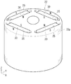
回転子20の回転子本体22は、絶縁された鋼板22pを軸方向に積層することで、図3に示すように、円柱形に形成されている。回転子本体22には、図4に示すように、扁平六角形のスリット状に形成された磁石挿入穴25がその回転子本体22の一端側から他端側まで軸方向に延びるように形成されている。磁石挿入穴25は、回転子本体22の円周方向に等間隔で四個形成されている。そして、それらの磁石挿入穴25が、図1、図3に示すように、回転子本体22の外周面に重なる仮想円に内接する正方形の各辺を構成するように位置決めされている。即ち、四個の磁石挿入穴25は、回転子本体22の中心を挟んで対向するように配置された二組の磁石挿入穴25からなり、一方の組の磁石挿入穴25と他方の組の磁石挿入穴25とが位相を90°ずらした状態で配置されている。
回転子20は、図1に示すように、同軸に設けられた回転子本体22と回転中心軸24とを備えており、前記回転中心軸24の一端側と他端側とが固定子50の軸受(図示省略)によって支持されている。これにより、回転子20は、固定子50と同軸に保持された状態で、その固定子50内に収納される。
回転子20の回転子本体22は、絶縁された鋼板22pを軸方向に積層することで、図3に示すように、円柱形に形成されている。回転子本体22には、図4に示すように、扁平六角形のスリット状に形成された磁石挿入穴25がその回転子本体22の一端側から他端側まで軸方向に延びるように形成されている。磁石挿入穴25は、回転子本体22の円周方向に等間隔で四個形成されている。そして、それらの磁石挿入穴25が、図1、図3に示すように、回転子本体22の外周面に重なる仮想円に内接する正方形の各辺を構成するように位置決めされている。即ち、四個の磁石挿入穴25は、回転子本体22の中心を挟んで対向するように配置された二組の磁石挿入穴25からなり、一方の組の磁石挿入穴25と他方の組の磁石挿入穴25とが位相を90°ずらした状態で配置されている。
回転子本体22の磁石挿入穴25には、図4、図5等に示すように、永久磁石30が挿入されるようになっている。永久磁石30は、角形の板状に形成されており、その表面側と裏面側とに磁極が設けられている(図3参照)。そして、図5に示すように、永久磁石30の長さ寸法(回転子本体22の軸方向の長さ寸法)が磁石挿入穴25の長さ寸法L(回転子本体22の軸長寸法)にほぼ等しい値に設定されている。
回転子本体22の磁石挿入穴25には、図4に示すように、永久磁石30を厚み方向から挟めるように構成された一対の厚み方向拘束面25kが形成されている。そして、厚み方向拘束面25kの幅方向両側(図4の左右両側)の位置に、その磁石挿入穴25を幅方向外側に拡開させるV溝状のV形端面25vが形成されている。また、各々の厚み方向拘束面25kには、左右のV形端面25vの近傍位置に永久磁石30の挿入方向、即ち、回転子本体22の軸方向に延びるレール状の突条26が形成されている。
回転子本体22の磁石挿入穴25には、図4に示すように、永久磁石30を厚み方向から挟めるように構成された一対の厚み方向拘束面25kが形成されている。そして、厚み方向拘束面25kの幅方向両側(図4の左右両側)の位置に、その磁石挿入穴25を幅方向外側に拡開させるV溝状のV形端面25vが形成されている。また、各々の厚み方向拘束面25kには、左右のV形端面25vの近傍位置に永久磁石30の挿入方向、即ち、回転子本体22の軸方向に延びるレール状の突条26が形成されている。
突条26は、永久磁石30を磁石挿入穴25の幅方向中央に位置決めするためのものであり、断面半楕円形に形成されて、一方の厚み方向拘束面25kの突条26と他方の厚み方向拘束面25kの突条26とが対向する位置(幅方向において重なる位置)に形成されている。また、左側の突条26と右側の突条26との間隔は、図4に示すように、永久磁石30の幅寸法W1にほぼ等しい寸法に設定されている。
さらに、一方の厚み方向拘束面25kと他方の厚み方向拘束面25kとの間隔T0、即ち、磁石挿入穴25のスリット幅寸法T0は、永久磁石30が磁石挿入穴25に挿入された状態で、両側の厚み方向拘束面25kと永久磁石30間にそれぞれ所定寸法の隙間SL(30μm~40μm)が形成されるような値に設定されている。即ち、磁石挿入穴25のスリット幅寸法T0は、永久磁石30の厚み寸法T1よりも隙間(SL×2)程度大きな値に設定されている。また、永久磁石30の四隅の角部が断面半楕円形の突条26の傾斜側面にそれぞれ当接するようになる。
このため、図4、図5に示すように、四隅の突条26を利用して永久磁石30を磁石挿入穴25に挿入した状態で、永久磁石30の厚み方向両側には所定寸法の隙間SLが形成されるとともに、永久磁石30の幅方向両側には、略五角形状の空間SPが形成されるようになる。
即ち、前記突条26が本発明の突起に相当する。
さらに、一方の厚み方向拘束面25kと他方の厚み方向拘束面25kとの間隔T0、即ち、磁石挿入穴25のスリット幅寸法T0は、永久磁石30が磁石挿入穴25に挿入された状態で、両側の厚み方向拘束面25kと永久磁石30間にそれぞれ所定寸法の隙間SL(30μm~40μm)が形成されるような値に設定されている。即ち、磁石挿入穴25のスリット幅寸法T0は、永久磁石30の厚み寸法T1よりも隙間(SL×2)程度大きな値に設定されている。また、永久磁石30の四隅の角部が断面半楕円形の突条26の傾斜側面にそれぞれ当接するようになる。
このため、図4、図5に示すように、四隅の突条26を利用して永久磁石30を磁石挿入穴25に挿入した状態で、永久磁石30の厚み方向両側には所定寸法の隙間SLが形成されるとともに、永久磁石30の幅方向両側には、略五角形状の空間SPが形成されるようになる。
即ち、前記突条26が本発明の突起に相当する。
回転子本体22は、各々の磁石挿入穴25に永久磁石30が挿入された状態で、電着塗装される。ここで、電着塗装とは、水溶性の電着塗料の中に被塗物(回転子本体22)を浸漬させてこれを陰極とし、電着塗料中の陽極から陰極に直流電流を流すことで、被塗物の塗装を行なうものである。即ち、陰極(回転子本体22)の付近では、塗料が化学反応を起こして不溶性の樹脂(絶縁材料)となり、回転子本体22の表面に塗膜Rが形成されるとともに、その回転子本体22の隙間部分にも樹脂が浸透して絶縁性の塗膜Rが形成されるようになる。
これにより、回転子本体22の表面に位置する永久磁石30の長さ方向両端面32が、図6に示すように、塗膜Rによって覆われるとともに、図4において、永久磁石30と磁石挿入穴25の隙間SLが塗膜R(図6参照)で塞がれるようになる。さらに、磁石挿入穴25の略五角形状の空間SPの内周面、及びその内周面を構成する永久磁石30の幅方向両端面34(図4参照)が塗膜Rによって覆われるようになる。即ち、永久磁石30は、その表面が全体的に塗膜Rによって覆われるようになる。
このように、永久磁石30の表面が絶縁性の塗膜Rに覆われるため、永久磁石30を流れる渦電流を低減させることができ、前記永久磁石30の発熱を抑えることができる。
また、図6に示すように、磁石挿入穴25の位置で回転子本体22を構成する鋼板22p間に積層不良等による隙間が形成されていても、その部分に塗膜Rが浸透するようになる。
これにより、回転子本体22の表面に位置する永久磁石30の長さ方向両端面32が、図6に示すように、塗膜Rによって覆われるとともに、図4において、永久磁石30と磁石挿入穴25の隙間SLが塗膜R(図6参照)で塞がれるようになる。さらに、磁石挿入穴25の略五角形状の空間SPの内周面、及びその内周面を構成する永久磁石30の幅方向両端面34(図4参照)が塗膜Rによって覆われるようになる。即ち、永久磁石30は、その表面が全体的に塗膜Rによって覆われるようになる。
このように、永久磁石30の表面が絶縁性の塗膜Rに覆われるため、永久磁石30を流れる渦電流を低減させることができ、前記永久磁石30の発熱を抑えることができる。
また、図6に示すように、磁石挿入穴25の位置で回転子本体22を構成する鋼板22p間に積層不良等による隙間が形成されていても、その部分に塗膜Rが浸透するようになる。
<モータ10の製造方法について>
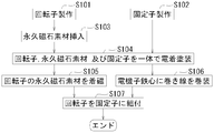
次に、図8に示すフローチャートに基づいて、上記したモータ10の製造方法について説明する。
先ず、回転子20の鉄心部分と固定子50の鉄心部分とが別工程でそれぞれ製造される(ステップS101、S102)。次に、回転子20の回転子本体22に形成された磁石挿入穴25に永久磁石30の素材が挿入される(ステップS103)。このとき、永久磁石30の素材を、図4に示すように、磁石挿入穴25に形成された突条26により幅方向両側から拘束し、前記永久磁石30の素材を突条26に沿って磁石挿入穴25に挿入する。このようにして、永久磁石30の素材が磁石挿入穴25に挿入された状態で、永久磁石30の素材は突条26を介して回転子本体22と電気的に接続されるようになる。
次に、回転子20の鉄心部分を固定子50の鉄心部分に挿入し、同軸に保持した状態で、両者20,50を水溶性の電着塗料の中に浸漬させて電着塗装を行なう(ステップS104)。
次に、図8に示すフローチャートに基づいて、上記したモータ10の製造方法について説明する。
先ず、回転子20の鉄心部分と固定子50の鉄心部分とが別工程でそれぞれ製造される(ステップS101、S102)。次に、回転子20の回転子本体22に形成された磁石挿入穴25に永久磁石30の素材が挿入される(ステップS103)。このとき、永久磁石30の素材を、図4に示すように、磁石挿入穴25に形成された突条26により幅方向両側から拘束し、前記永久磁石30の素材を突条26に沿って磁石挿入穴25に挿入する。このようにして、永久磁石30の素材が磁石挿入穴25に挿入された状態で、永久磁石30の素材は突条26を介して回転子本体22と電気的に接続されるようになる。
次に、回転子20の鉄心部分を固定子50の鉄心部分に挿入し、同軸に保持した状態で、両者20,50を水溶性の電着塗料の中に浸漬させて電着塗装を行なう(ステップS104)。
これにより、固定子50の鉄心部分の表面と、回転子20の鉄心部分の表面、及び永久磁石30の表面が絶縁性の塗膜Rに覆われるとともに、前述のように、永久磁石30と磁石挿入穴25の隙間SL等が塗膜Rによって塞がれるようになる。
次に、電着塗装後、回転子20の永久磁石30の素材に外部から磁界を加えて、それらの永久磁石30の素材をそれぞれ着磁する(ステップS105)。この段階で、前記素材が永久磁石30として機能するようになる。
また、永久磁石30の素材の着磁と平行して、固定子50の電機子鉄心52に電機子巻線54を巻装する(ステップS106)。
このようにして、回転子20と固定子50とが製造された状態で、その固定子50に回転子20を組付け、モータ10が完成する(ステップS107)。
次に、電着塗装後、回転子20の永久磁石30の素材に外部から磁界を加えて、それらの永久磁石30の素材をそれぞれ着磁する(ステップS105)。この段階で、前記素材が永久磁石30として機能するようになる。
また、永久磁石30の素材の着磁と平行して、固定子50の電機子鉄心52に電機子巻線54を巻装する(ステップS106)。
このようにして、回転子20と固定子50とが製造された状態で、その固定子50に回転子20を組付け、モータ10が完成する(ステップS107)。
<本実施形態に係るモータ10の回転子20の長所>
本発明によると、回転子本体22の磁石挿入穴25は、その磁石挿入穴25の内壁面(厚み方向拘束面25k)と永久磁石30間に隙間SL等が形成されるように、永久磁石30に対して大きく形成されている。しかし、磁石挿入穴25の厚み方向拘束面25kには複数の突起(突条26)が形成されているため、永久磁石30がその磁石挿入穴25に挿入される際、挿入方向に対して直角方向に位置ずれすることがなく、その永久磁石30を前記磁石挿入穴25内の定位置に配置できるようになる。
さらに、磁石挿入穴25の厚み方向拘束面25kと永久磁石30間の隙間SLは、電着塗装により形成された絶縁性の塗膜Rによって塞がれている。即ち、永久磁石30が回転子本体22の磁石挿入穴25に挿入された後で、その永久磁石30の表面が絶縁性の塗膜Rによって覆われる。このため、永久磁石30の表面の絶縁層(塗膜)に傷が付くことがない。
さらに、回転子本体22の磁石挿入穴25と永久磁石30間の隙間SLが塗膜Rによって塞がれるため、モータ10の駆動時に磁石挿入穴25と永久磁石30間で振動が発生し難くなる。
本発明によると、回転子本体22の磁石挿入穴25は、その磁石挿入穴25の内壁面(厚み方向拘束面25k)と永久磁石30間に隙間SL等が形成されるように、永久磁石30に対して大きく形成されている。しかし、磁石挿入穴25の厚み方向拘束面25kには複数の突起(突条26)が形成されているため、永久磁石30がその磁石挿入穴25に挿入される際、挿入方向に対して直角方向に位置ずれすることがなく、その永久磁石30を前記磁石挿入穴25内の定位置に配置できるようになる。
さらに、磁石挿入穴25の厚み方向拘束面25kと永久磁石30間の隙間SLは、電着塗装により形成された絶縁性の塗膜Rによって塞がれている。即ち、永久磁石30が回転子本体22の磁石挿入穴25に挿入された後で、その永久磁石30の表面が絶縁性の塗膜Rによって覆われる。このため、永久磁石30の表面の絶縁層(塗膜)に傷が付くことがない。
さらに、回転子本体22の磁石挿入穴25と永久磁石30間の隙間SLが塗膜Rによって塞がれるため、モータ10の駆動時に磁石挿入穴25と永久磁石30間で振動が発生し難くなる。
また、永久磁石30が突条26によって幅方向両側から拘束されるため、磁石挿入穴25の幅寸法を永久磁石30の幅寸法よりも大きくして、その永久磁石30の幅方向両側位置に広い空間SPを形成できる。これにより、前記永久磁石30の表側(例えば、N極)から裏側(例えば、S極)に磁束が通り難くなる。即ち、前記永久磁石30の磁束を効率的に回転子本体22の外周面から固定子50側に導けるようになる。
また、永久磁石30の素材を磁石挿入穴25に挿入した後、その永久磁石30の素材を着磁するため、磁石挿入穴25に対する永久磁石30の素材の挿入が容易になる。
また、永久磁石30の素材を磁石挿入穴25に挿入した後、その永久磁石30の素材を着磁するため、磁石挿入穴25に対する永久磁石30の素材の挿入が容易になる。
<変更例>
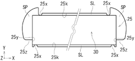
ここで、本発明は上記実施形態に限定されるものではなく、本発明の要旨を逸脱しない範囲における変更が可能である。例えば、本実施形態では、磁石挿入穴25を扁平六角形のスリット状に形成し、その磁石挿入穴25の厚み方向拘束面25kに永久磁石30を幅方向両側から拘束する突条26を形成する例を示した。しかし、図7に示すように、磁石挿入穴25の厚み方向拘束面25kに永久磁石30との隙間SLを一定寸法に保持するための隙間保持突起25xを形成し、さらに、磁石挿入穴25の幅方法両側に永久磁石30を幅方向両側から拘束して回転子本体22の軸方向にガイドするガイド面25yを有するガイド突起25zを設けるようにすることも可能である。
このように、隙間保持突起25xにより磁石挿入穴25の厚み方向拘束面25kと永久磁石30との隙間SLを一定寸法に保持できるため、電着塗装による塗膜の厚み寸法がほぼ一定になる。
また、本実施形態では、永久磁石30の素材を回転子本体22の磁石挿入穴25に挿入した後、回転子本体22に磁界を加えて永久磁石30の素材を着磁する例を示したが、図7に示すように磁石挿入穴25を形成することで、その磁石挿入穴25に着磁済みの永久磁石30を挿入しても隙間SLを一定寸法に保持できる。
ここで、本発明は上記実施形態に限定されるものではなく、本発明の要旨を逸脱しない範囲における変更が可能である。例えば、本実施形態では、磁石挿入穴25を扁平六角形のスリット状に形成し、その磁石挿入穴25の厚み方向拘束面25kに永久磁石30を幅方向両側から拘束する突条26を形成する例を示した。しかし、図7に示すように、磁石挿入穴25の厚み方向拘束面25kに永久磁石30との隙間SLを一定寸法に保持するための隙間保持突起25xを形成し、さらに、磁石挿入穴25の幅方法両側に永久磁石30を幅方向両側から拘束して回転子本体22の軸方向にガイドするガイド面25yを有するガイド突起25zを設けるようにすることも可能である。
このように、隙間保持突起25xにより磁石挿入穴25の厚み方向拘束面25kと永久磁石30との隙間SLを一定寸法に保持できるため、電着塗装による塗膜の厚み寸法がほぼ一定になる。
また、本実施形態では、永久磁石30の素材を回転子本体22の磁石挿入穴25に挿入した後、回転子本体22に磁界を加えて永久磁石30の素材を着磁する例を示したが、図7に示すように磁石挿入穴25を形成することで、その磁石挿入穴25に着磁済みの永久磁石30を挿入しても隙間SLを一定寸法に保持できる。
10・・・・モータ
20・・・・回転子
22・・・・回転子本体
25・・・・磁石挿入穴
25x・・・隙間保持突起
25k・・・厚み方向拘束面
25y・・・ガイド面
26・・・・突条
30・・・・永久磁石
50・・・・固定子
54・・・・電機子巻線
R・・・・・塗膜
SL・・・・隙間
20・・・・回転子
22・・・・回転子本体
25・・・・磁石挿入穴
25x・・・隙間保持突起
25k・・・厚み方向拘束面
25y・・・ガイド面
26・・・・突条
30・・・・永久磁石
50・・・・固定子
54・・・・電機子巻線
R・・・・・塗膜
SL・・・・隙間
Claims (5)
- 円柱形の回転子本体と、前記回転子本体の円周方向に等間隔で配置されており、その回転子本体の軸方向に延びるように形成された複数の磁石挿入穴と、それらの磁石挿入穴にそれぞれ挿入される複数の永久磁石とを有するモータの回転子であって、
前記磁石挿入穴は、前記永久磁石が隙間を介した状態で挿入されるように構成されており、さらに前記磁石挿入穴の内壁面には、前記永久磁石がその磁石挿入穴に挿入される際、前記回転子本体の軸方向に対して直角方向に変位しないように、その永久磁石を拘束する複数の突起が設けられており、
前記磁石挿入穴の内壁面と前記永久磁石間の前記隙間が前記永久磁石挿入後の前記回転子本体を電着塗装することにより形成された絶縁性の塗膜によって塞がれていることを特徴とするモータの回転子。 - 請求項1に記載されたモータの回転子であって、
前記永久磁石は角形の板状に形成されており、
前記磁石挿入穴の内壁面は、前記隙間を介した状態で、前記永久磁石を厚み方向から挟めるように構成された一対の厚み方向拘束面を有しており、
前記突起は、前記厚み方向拘束面に形成されて、前記永久磁石を幅方向両側から拘束し、前記回転子本体の軸方向にガイドできるように構成されていることを特徴とするモータの回転子。 - 請求項1に記載されたモータの回転子であって、
前記永久磁石は角形の板状に形成されており、
前記磁石挿入穴の内壁面は、前記隙間を介した状態で、前記永久磁石を厚み方向から挟めるように構成された一対の厚み方向拘束面を有しており、
前記突起は、両側の厚み方向拘束面に形成されて、それらの厚み方向拘束面と前記永久磁石間の隙間を一定寸法に保持する隙間保持突起と、前記永久磁石を幅方向両側から拘束してその永久磁石を前記回転子本体の軸方向にガイド可能に形成されたガイド面を備えるガイド突起とから構成されていることを特徴とするモータの回転子。 - 円柱形の回転子本体と、前記回転子本体の円周方向に等間隔で配置されており、その回転子本体の軸方向に延びるように形成された複数の磁石挿入穴と、それらの磁石挿入穴にそれぞれ挿入される複数の永久磁石とを有するモータの回転子の製造方法であって、
前記永久磁石が隙間を介した状態で挿入されるように前記磁石挿入穴を形成する工程と、
前記磁石挿入穴を形成する際に、前記永久磁石が挿入時に前記回転子本体の軸方向に対して直角方向に変位しないように、その永久磁石を拘束する複数の突起をその磁石挿入穴の内壁面に形成する工程と、
前記磁石挿入穴に前記永久磁石の素材を挿入する工程と、
前記永久磁石の素材が挿入された前記回転子本体を電着塗装し、前記磁石挿入穴の内壁面と前記永久磁石の素材間の隙間を絶縁性の塗膜で塞ぐ工程と、
前記電着塗装工程の後、前記永久磁石の素材を着磁する工程と、
を有することを特徴とするモータの回転子の製造方法。 - 円柱形の回転子本体と、前記回転子本体の円周方向に等間隔で配置されており、その回転子本体の軸方向に延びるように形成された複数の磁石挿入穴と、それらの磁石挿入穴にそれぞれ挿入される複数の永久磁石とを有するモータの回転子の製造方法であって、
前記永久磁石が隙間を介した状態で挿入されるように前記磁石挿入穴を形成する工程と、
前記磁石挿入穴を形成する際に、前記永久磁石が挿入時に前記回転子本体の軸方向に対して直角方向に変位しないように、その永久磁石を拘束する複数の突起をその磁石挿入穴の内壁面に形成する工程と、
前記磁石挿入穴に前記永久磁石を挿入する工程と、
前記永久磁石が挿入された前記回転子本体を電着塗装し、前記磁石挿入穴の内壁面と前記永久磁石間の隙間を絶縁性の塗膜で塞ぐ工程と、
を有することを特徴とするモータの回転子の製造方法。
Applications Claiming Priority (2)
| Application Number | Priority Date | Filing Date | Title |
|---|---|---|---|
| JP2010-228219 | 2010-10-08 | ||
| JP2010228219A JP2012085409A (ja) | 2010-10-08 | 2010-10-08 | モータの回転子及びその回転子の製造方法 |
Publications (1)
| Publication Number | Publication Date |
|---|---|
| WO2012046465A1 true WO2012046465A1 (ja) | 2012-04-12 |
Family
ID=45927466
Family Applications (1)
| Application Number | Title | Priority Date | Filing Date |
|---|---|---|---|
| PCT/JP2011/055749 Ceased WO2012046465A1 (ja) | 2010-10-08 | 2011-03-11 | モータの回転子及びその回転子の製造方法 |
Country Status (2)
| Country | Link |
|---|---|
| JP (1) | JP2012085409A (ja) |
| WO (1) | WO2012046465A1 (ja) |
Families Citing this family (2)
| Publication number | Priority date | Publication date | Assignee | Title |
|---|---|---|---|---|
| JP6827544B2 (ja) * | 2017-08-01 | 2021-02-10 | 三菱電機株式会社 | モータ、及びロータの製造方法 |
| JP2020108277A (ja) * | 2018-12-27 | 2020-07-09 | 本田技研工業株式会社 | 回転電機のロータ |
Citations (5)
| Publication number | Priority date | Publication date | Assignee | Title |
|---|---|---|---|---|
| JPH104643A (ja) * | 1996-06-13 | 1998-01-06 | Aichi Emerson Electric Co Ltd | 磁石回転子 |
| JP2001073948A (ja) * | 1999-07-02 | 2001-03-21 | Matsushita Refrig Co Ltd | 電動圧縮機 |
| JP2001086671A (ja) * | 1999-09-13 | 2001-03-30 | Sumitomo Special Metals Co Ltd | モーター用磁石とその固定方法並びにモーター |
| JP2007068318A (ja) * | 2005-08-31 | 2007-03-15 | Matsushita Electric Ind Co Ltd | 磁石埋込型モータ |
| JP2008109777A (ja) * | 2006-10-25 | 2008-05-08 | Toyota Motor Corp | ロータ、回転電動機およびロータの製造方法 |
-
2010
- 2010-10-08 JP JP2010228219A patent/JP2012085409A/ja active Pending
-
2011
- 2011-03-11 WO PCT/JP2011/055749 patent/WO2012046465A1/ja not_active Ceased
Patent Citations (5)
| Publication number | Priority date | Publication date | Assignee | Title |
|---|---|---|---|---|
| JPH104643A (ja) * | 1996-06-13 | 1998-01-06 | Aichi Emerson Electric Co Ltd | 磁石回転子 |
| JP2001073948A (ja) * | 1999-07-02 | 2001-03-21 | Matsushita Refrig Co Ltd | 電動圧縮機 |
| JP2001086671A (ja) * | 1999-09-13 | 2001-03-30 | Sumitomo Special Metals Co Ltd | モーター用磁石とその固定方法並びにモーター |
| JP2007068318A (ja) * | 2005-08-31 | 2007-03-15 | Matsushita Electric Ind Co Ltd | 磁石埋込型モータ |
| JP2008109777A (ja) * | 2006-10-25 | 2008-05-08 | Toyota Motor Corp | ロータ、回転電動機およびロータの製造方法 |
Also Published As
| Publication number | Publication date |
|---|---|
| JP2012085409A (ja) | 2012-04-26 |
Similar Documents
| Publication | Publication Date | Title |
|---|---|---|
| JP5328821B2 (ja) | 回転電機用回転子 | |
| US10879778B2 (en) | Rotor of rotating electric machine and manufacturing method of the same | |
| CN102629790B (zh) | 用于旋转电机的转子 | |
| JP5239200B2 (ja) | 永久磁石式回転電機 | |
| JP5372296B2 (ja) | 永久磁石型回転電機 | |
| US20180041080A1 (en) | Rotor, rotary electric machine, and method for manufacturing rotor | |
| CN108141073B (zh) | 转子以及旋转电机 | |
| JP2011223836A (ja) | 永久磁石式回転電機 | |
| JP5725202B2 (ja) | 電動機 | |
| JP5347588B2 (ja) | 埋め込み磁石式モータ | |
| CN207518374U (zh) | 无刷电动机 | |
| JP2015061328A (ja) | 回転電機のロータ | |
| JP6357859B2 (ja) | 永久磁石埋め込み式回転電機 | |
| JP5228316B2 (ja) | 回転電機の回転子及び回転電機 | |
| JP6112970B2 (ja) | 永久磁石式回転電機 | |
| WO2012046465A1 (ja) | モータの回転子及びその回転子の製造方法 | |
| JP5971142B2 (ja) | 回転電機の磁石埋め込み型ロータおよび回転電機 | |
| CN109962546A (zh) | 转子 | |
| CN106063085B (zh) | 转子 | |
| US11901773B2 (en) | Rotating electric machine | |
| JP2019068655A (ja) | 回転電機のロータ | |
| JP7038527B2 (ja) | 回転電機用磁性くさび、回転電機用磁性くさびの製造方法、および、回転電機 | |
| JP2023139933A (ja) | 永久磁石式回転子および永久磁石式回転電機 | |
| JP2008278683A (ja) | ステータ | |
| JP2012235608A (ja) | 同期電動機 |
Legal Events
| Date | Code | Title | Description |
|---|---|---|---|
| 121 | Ep: the epo has been informed by wipo that ep was designated in this application |
Ref document number: 11830399 Country of ref document: EP Kind code of ref document: A1 |
|
| NENP | Non-entry into the national phase |
Ref country code: DE |
|
| 122 | Ep: pct application non-entry in european phase |
Ref document number: 11830399 Country of ref document: EP Kind code of ref document: A1 |