WO2012046366A1 - 画像再生方法、画像再生装置、画像再生プログラム、撮像システム、および再生システム - Google Patents
画像再生方法、画像再生装置、画像再生プログラム、撮像システム、および再生システム Download PDFInfo
- Publication number
- WO2012046366A1 WO2012046366A1 PCT/JP2011/003347 JP2011003347W WO2012046366A1 WO 2012046366 A1 WO2012046366 A1 WO 2012046366A1 JP 2011003347 W JP2011003347 W JP 2011003347W WO 2012046366 A1 WO2012046366 A1 WO 2012046366A1
- Authority
- WO
- WIPO (PCT)
- Prior art keywords
- image
- picture
- decoding
- memory
- reference image
- Prior art date
- Legal status (The legal status is an assumption and is not a legal conclusion. Google has not performed a legal analysis and makes no representation as to the accuracy of the status listed.)
- Ceased
Links
Images


Classifications
-
- H—ELECTRICITY
- H04—ELECTRIC COMMUNICATION TECHNIQUE
- H04N—PICTORIAL COMMUNICATION, e.g. TELEVISION
- H04N19/00—Methods or arrangements for coding, decoding, compressing or decompressing digital video signals
- H04N19/50—Methods or arrangements for coding, decoding, compressing or decompressing digital video signals using predictive coding
-
- H—ELECTRICITY
- H04—ELECTRIC COMMUNICATION TECHNIQUE
- H04N—PICTORIAL COMMUNICATION, e.g. TELEVISION
- H04N19/00—Methods or arrangements for coding, decoding, compressing or decompressing digital video signals
- H04N19/10—Methods or arrangements for coding, decoding, compressing or decompressing digital video signals using adaptive coding
- H04N19/102—Methods or arrangements for coding, decoding, compressing or decompressing digital video signals using adaptive coding characterised by the element, parameter or selection affected or controlled by the adaptive coding
- H04N19/103—Selection of coding mode or of prediction mode
-
- H—ELECTRICITY
- H04—ELECTRIC COMMUNICATION TECHNIQUE
- H04N—PICTORIAL COMMUNICATION, e.g. TELEVISION
- H04N19/00—Methods or arrangements for coding, decoding, compressing or decompressing digital video signals
- H04N19/10—Methods or arrangements for coding, decoding, compressing or decompressing digital video signals using adaptive coding
- H04N19/134—Methods or arrangements for coding, decoding, compressing or decompressing digital video signals using adaptive coding characterised by the element, parameter or criterion affecting or controlling the adaptive coding
- H04N19/156—Availability of hardware or computational resources, e.g. encoding based on power-saving criteria
-
- H—ELECTRICITY
- H04—ELECTRIC COMMUNICATION TECHNIQUE
- H04N—PICTORIAL COMMUNICATION, e.g. TELEVISION
- H04N19/00—Methods or arrangements for coding, decoding, compressing or decompressing digital video signals
- H04N19/10—Methods or arrangements for coding, decoding, compressing or decompressing digital video signals using adaptive coding
- H04N19/169—Methods or arrangements for coding, decoding, compressing or decompressing digital video signals using adaptive coding characterised by the coding unit, i.e. the structural portion or semantic portion of the video signal being the object or the subject of the adaptive coding
- H04N19/17—Methods or arrangements for coding, decoding, compressing or decompressing digital video signals using adaptive coding characterised by the coding unit, i.e. the structural portion or semantic portion of the video signal being the object or the subject of the adaptive coding the unit being an image region, e.g. an object
- H04N19/172—Methods or arrangements for coding, decoding, compressing or decompressing digital video signals using adaptive coding characterised by the coding unit, i.e. the structural portion or semantic portion of the video signal being the object or the subject of the adaptive coding the unit being an image region, e.g. an object the region being a picture, frame or field
-
- H—ELECTRICITY
- H04—ELECTRIC COMMUNICATION TECHNIQUE
- H04N—PICTORIAL COMMUNICATION, e.g. TELEVISION
- H04N19/00—Methods or arrangements for coding, decoding, compressing or decompressing digital video signals
- H04N19/10—Methods or arrangements for coding, decoding, compressing or decompressing digital video signals using adaptive coding
- H04N19/169—Methods or arrangements for coding, decoding, compressing or decompressing digital video signals using adaptive coding characterised by the coding unit, i.e. the structural portion or semantic portion of the video signal being the object or the subject of the adaptive coding
- H04N19/186—Methods or arrangements for coding, decoding, compressing or decompressing digital video signals using adaptive coding characterised by the coding unit, i.e. the structural portion or semantic portion of the video signal being the object or the subject of the adaptive coding the unit being a colour or a chrominance component
-
- H—ELECTRICITY
- H04—ELECTRIC COMMUNICATION TECHNIQUE
- H04N—PICTORIAL COMMUNICATION, e.g. TELEVISION
- H04N19/00—Methods or arrangements for coding, decoding, compressing or decompressing digital video signals
- H04N19/10—Methods or arrangements for coding, decoding, compressing or decompressing digital video signals using adaptive coding
- H04N19/189—Methods or arrangements for coding, decoding, compressing or decompressing digital video signals using adaptive coding characterised by the adaptation method, adaptation tool or adaptation type used for the adaptive coding
- H04N19/192—Methods or arrangements for coding, decoding, compressing or decompressing digital video signals using adaptive coding characterised by the adaptation method, adaptation tool or adaptation type used for the adaptive coding the adaptation method, adaptation tool or adaptation type being iterative or recursive
- H04N19/194—Methods or arrangements for coding, decoding, compressing or decompressing digital video signals using adaptive coding characterised by the adaptation method, adaptation tool or adaptation type used for the adaptive coding the adaptation method, adaptation tool or adaptation type being iterative or recursive involving only two passes
-
- H—ELECTRICITY
- H04—ELECTRIC COMMUNICATION TECHNIQUE
- H04N—PICTORIAL COMMUNICATION, e.g. TELEVISION
- H04N19/00—Methods or arrangements for coding, decoding, compressing or decompressing digital video signals
- H04N19/42—Methods or arrangements for coding, decoding, compressing or decompressing digital video signals characterised by implementation details or hardware specially adapted for video compression or decompression, e.g. dedicated software implementation
- H04N19/43—Hardware specially adapted for motion estimation or compensation
- H04N19/433—Hardware specially adapted for motion estimation or compensation characterised by techniques for memory access
-
- H—ELECTRICITY
- H04—ELECTRIC COMMUNICATION TECHNIQUE
- H04N—PICTORIAL COMMUNICATION, e.g. TELEVISION
- H04N19/00—Methods or arrangements for coding, decoding, compressing or decompressing digital video signals
- H04N19/44—Decoders specially adapted therefor, e.g. video decoders which are asymmetric with respect to the encoder
Definitions
- the present invention relates to an image reproduction technique, and in particular, image reproduction that decodes and reproduces a moving image stream encoded using inter-frame predictive encoding that compresses the amount of information by reducing redundancy in the time direction. It is about.
- MPEG-2 ISO / IEC 13818-2
- MPEG-4 ISO / IEC 449 14496-2
- H.264 etc.
- Video encoding technology such as H.264 (ISO / IEC 14496-10) has been actively researched and applied in various fields such as computers, communications, consumer AV equipment and broadcasting.
- intra prediction prediction for reducing redundancy in the spatial direction on the same screen and prediction pictures by referring to previous and subsequent pictures (reference pictures) that have already been encoded and decoded.
- inter-frame prediction encoding that reduces temporal redundancy by encoding the difference value between the generated predicted image and the encoding target picture.
- the amount of information is compressed.
- a reference picture memory for temporarily storing a reference picture is required to generate a predicted picture.
- an external memory such as a DRAM or a mixed memory built in the system LSI is generally used, and memory access is generated to the reference image memory in order to generate a predicted image. .
- a high bandwidth memory bandwidth for example, a plurality of DRAMs having a data bit width of 32 bits are used, or an operation is performed at a high operating frequency such as LPDDR2 (Low ⁇ Power Double ⁇ Data Rate 2) -SDRAM. It is necessary to use a high-performance DRAM capable. However, in either case, there is a problem that it is difficult to reduce the cost and save power because the mounting cost increases and the power consumption increases. In particular, small consumer cameras such as digital video cameras and digital still cameras that operate with a small battery have a very high need for low cost and low power consumption. Therefore, low cost and low power consumption in decoding video streams There is a lot of research on this.
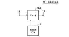
- FIG. 11 is a diagram simply showing a general image reproducing apparatus that inputs a moving image stream, sequentially decodes and outputs a reproduced image.
- a moving image stream to be reproduced is input from the input terminal 2, and the decoder 603 sequentially decodes the picture layer, slice layer, and macroblock layer for each picture.
- the decoded picture is output from the output terminal 13 to a display control unit (not shown).
- a picture for example, an I / P picture
- a reference image memory 5 and temporarily stored.
- reference pictures stored in the reference picture memory 5 are sequentially read out to generate a prediction picture and decoded.
- the difference value is added and output from the output terminal 13 to a display control unit (not shown).
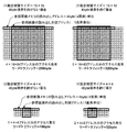
- the two-dimensional space of the reference image is based on the position of the macroblock to be decoded in the screen and the motion vector value. Is read out and converted to a read address of the reference image memory 5 (in the case of a memory having a 32-bit data bus, an address in units of four pixels).
- Fig. 13 (1) and (2) show an example.
- the calculated read start address in the two-dimensional space of the reference image matches the boundary of the read address of the reference image memory 5 (FIG. 13 (1))
- read for generating a predicted image of 16 ⁇ 16 pixels The read traffic sometimes generated is 256 bytes (64 addresses in units of 4 pixels), and no transfer including invalid pixels in reading occurs.
- the calculated read start address in the two-dimensional space of the reference image does not coincide with the read address boundary of the reference image memory 5 (FIG. 13 (2))
- a predicted image of 16 ⁇ 16 pixels is generated.
- the read traffic generated at the time of reading becomes 320 bytes (80 addresses in units of 4 pixels), and many transfers including invalid pixels in reading occur, and the overhead in reading increases.
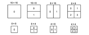
- MPEG-2 since the unit of motion compensation when generating the predicted image is a relatively large block unit composed of 16 ⁇ 16 pixels, the overhead generated at the time of reading is not a big problem.
- MPEG-4 supports not only 16 ⁇ 16 pixels but also 8 ⁇ 8 pixel units as motion compensation units.
- the read start address in the two-dimensional space of the calculated reference image is the reference image memory.
- the read traffic generated at the time of reading for generating a predicted image of 4 ⁇ 4 pixels is 16 bytes (4 addresses in units of 4 pixels).
- the read start address of the calculated reference image in the two-dimensional space does not coincide with the read address boundary of the reference image memory 5 (FIG. 13 (4))
- a predicted image of 4 ⁇ 4 pixels is generated.
- the read traffic generated at the time of reading is 32 bytes (equivalent to 8 addresses in units of 4 pixels), many transfers including invalid pixels in reading occur, and the overhead in reading is also motion compensation in units of 16 ⁇ 16 pixels. In comparison, it becomes larger.
- Specifications such as the capacity of the reference image memory, the bit width of the data bus, and the operating frequency are determined by the resolution and frame rate of video streams supported by the decoder (specified by the level in standards such as MPEG-2 and H.264). It is a matter.
- the specification of the reference image memory is determined on the assumption of the worst case that may occur within the standard range. For this reason, it is necessary to provide a high-performance reference image memory in a consumer-use compact camera or the like that supports HDTV video, and thus it has been difficult to realize cost reduction and power saving.
- worst case described here is specifically a case where a picture that has been inter-frame predictively encoded in a moving picture stream is encoded as follows.
- the reference image memory access that occurs to generate the predicted image is the transfer with the highest overhead including invalid transfer pixels in all macroblocks in the picture.
- the motion compensation size of the macroblock is the minimum size for all macroblocks in the picture. (For example, in the case of H.264, 4 ⁇ 4 pixels)
- a B picture capable of forward prediction / backward prediction / bidirectional prediction is encoded using bidirectional prediction in all macroblocks in the picture.
- Patent Documents 1 to 4 disclose technologies relating to memory bandwidth reduction that solve the above-described problems.
- the decoded image is reduced by filtering and stored in a reference image memory, and an image obtained by enlarging the reduced image read from the reference image memory by filtering is used as a reference image.
- Patent Document 3 an image obtained by compressing a decoded image by Hadamard transform and quantization is stored in a reference image memory, and an image obtained by decompressing a compressed image read from the reference image memory by inverse quantization and inverse Hadamard transform Are used as reference images.
- Patent Document 4 when a decoded image is stored in a reference image memory, compression distortion caused by irreversible conversion processing such as reduction or compression is temporally reduced when subsequent pictures are decoded. It is controlled adaptively so as not to accumulate.
- a decoded image is subjected to irreversible transformation processing such as filtering, Hadamard transformation, and quantization, and a reference image is obtained. Therefore, unnecessary compression distortion generated by the lossy conversion is superimposed on the reference image.
- MPEG-2 or H.264 which performs inter-screen predictive coding.
- the distortion of the reference image is superimposed on the next decoded image, and the decoded image on which the distortion is superimposed is used as the next reference image. Cumulatively.
- Patent Documents 1, 2, and 3 for a moving image stream that generates a large amount of memory access, such as a high-resolution image or a high frame rate image, the memory access amount that is generated when the moving image stream is actually decoded. Regardless of the size, if it is determined that the allowable memory bandwidth of the reference image memory is exceeded in advance assuming the worst case as described above, this reference image is always subjected to irreversible conversion to reduce memory access. Plan. For this reason, noise generated by this irreversible conversion is always accumulated over time, so that there is a problem that it is easy to be found visually as large noise in the reproduced decoded image.
- the memory access reduction method disclosed in Patent Document 4 uses two types of reference images, a compressed reference image and an uncompressed reference image, as a reference image memory in order to suppress temporal accumulation of compression distortion in the decoding process as described above.
- a picture such as a P picture in which compression distortion is accumulated over time
- it is decoded using a non-compressed reference image
- a picture such as a B picture in which compression distortion is not accumulated over time
- This is a technique for reducing memory bandwidth by decoding using a reference image.
- two types of reference images, a compressed reference image and an uncompressed reference image need to be stored in the reference image memory, and a much larger capacity memory is required.
- Patent Document 4 distortion generated when a reference image is compressed is reduced by applying a method of generating a predicted image using a compressed reference image to only a macroblock that is bidirectionally predicted.
- this can be said, for example, when the compression distortion in the forward prediction picture occurs on the positive side and the compression distortion in the backward prediction picture occurs on the negative side.
- the compression distortion in the forward prediction picture and the backward prediction picture both occur on the plus side or the minus side, the distortion that occurs when the reference image is compressed is not reduced. When decoded and reproduced, it may be visually confirmed as noise.
- an object of the present invention is to provide an image reproduction technique capable of suppressing temporal accumulation of compression distortion generated at the time of decoding at low cost and power saving.
- the second decoding step When a picture is to be stored in the reference picture memory as a reference picture after decoding, the decoding is performed based on traffic related to the picture that refers to the picture to be decoded, estimated in the first decoding step.
- the target picture is referred to as the reference image menu. It is to set the compression mode when storing the directory.
- the first decoding step traffic to the reference image memory is estimated for each picture of the moving image stream. Then, when the decoding target picture is a so-called reference picture in the second decoding step for generating the reproduced image, the traffic related to the picture that refers to the decoding target picture estimated in the first decoding step is Based on this, the compression mode when the decoding target picture is stored in the reference image memory is set. That is, since the compression mode for storing the reference image is set based on the memory access traffic analyzed in advance, it is possible to avoid, for example, a compression process that is less necessary, and thus compression that occurs at the time of decoding. The accumulation of distortion over time can be suppressed more than in the past. In addition, it is not necessary to mount an unnecessarily high-performance memory. For example, it is not necessary to unnecessarily increase the number of external memories or to operate the memory at a higher operating frequency.
- the compression mode when storing the reference image is set based on the memory access traffic analyzed in advance, the temporal accumulation of compression distortion occurring at the time of decoding is suppressed more than before. Can do.
- both cost reduction and power saving can be realized simultaneously.
- H. 2 is a diagram illustrating a motion compensation size in H.264. It is a figure which shows the relationship between motion compensation size and read traffic.
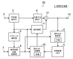
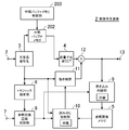
- FIG. 1 is a diagram illustrating a configuration of an image reproduction device 1 according to the first embodiment.
- a moving image stream to be reproduced is sequentially input to the input terminal 2.
- the variable length decoding unit 3 performs variable length decoding of the input video stream and outputs various encoding parameters and quantization coefficients.
- the coding parameters here include picture type (I / P / B picture), macroblock coding type (intra / inter), prediction direction type (forward prediction / backward prediction / bidirectional prediction), motion compensation. Includes size and motion vectors.
- the inverse quantization / inverse DCT unit 4 performs inverse quantization and inverse DCT transform on the quantization coefficient output from the variable length decoding unit 3.
- the reference image memory 5 temporarily stores the already decoded picture as a reference image.
- the traffic analysis unit 6 analyzes the traffic for the reference image memory 5 in advance in units of pictures based on the encoding parameters output from the variable length decoding unit 3.
- an allowable memory bandwidth (predetermined threshold value) of the reference image memory 5 is set.
- the reference image compression control unit 8 temporarily holds the traffic to the reference image memory 5 related to each picture calculated by the traffic analysis unit 6, and the allowable memory band set as the traffic related to the picture referring to the decoding target picture By comparing the width, the compression mode in storing the reference image in the reference image memory 5 is set.
- the writing control unit 9 controls the writing of the reference image to the reference image memory 5 according to the compression mode set by the reference image compression control unit 8.
- the read control unit 10 reads the reference image from the reference image memory 5 according to the decompression mode according to the compression mode set by the reference image compression control unit 8 and the motion vector output from the variable length decoding unit 3. Take control.
- the motion compensation unit 11 generates a predicted image from the reference image read by the read control unit 10 based on the motion vector output from the variable length decoding unit 3.
- the adder 12 outputs the image data output from the inverse quantization / inverse DCT unit 4 as it is for the macroblock subjected to intra prediction (intra) encoding, while being subjected to inter prediction (inter) encoding.
- the image data output from the inverse quantization / inverse DCT unit 4 and the predicted image output from the motion compensation unit 11 are added and output.
- the output terminal 13 outputs the output of the adder 12 as a reproduced image.
- variable length decoding unit 3 the inverse quantization / inverse DCT unit 4, the motion compensation unit 11, and the adder 12 constitute a decoding processing unit 20.
- the decoding processing unit 20 performs variable-length decoding on a per-picture predictive-coded moving image stream in units of pictures, generates a reproduction image, and sets an encoding parameter for estimating traffic to the reference image memory 5. Other configurations may be used as long as they are output.
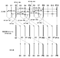
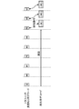
- FIG. 2 is a diagram illustrating an example of a picture configuration of a moving image stream.
- each picture of the moving image stream is shown in the order of input, the middle part in the order of encoding, and the lower part in the order of reproduction.
- the reference picture is indicated by a bold solid line and bold characters.
- the reference picture of each picture (P / B picture) encoded using inter-picture predictive coding, and the read traffic (RT) of the reference picture generated to generate the predicted picture are shown. Is shown.
- the reference picture for forward prediction of the B3 picture located fifth in the coding order is the I2 picture
- read traffic for I2 picture reference generated when decoding the B3 picture is “RT (I2 ⁇ B3 ) ”.
- the reference picture for backward prediction of the B3 picture is the P5 picture
- the read traffic for referring to the P5 picture generated when the B3 picture is decoded is shown as “RT (B3 ⁇ P5)”.
- WT write traffic
- I2 picture the write traffic of the I2 picture
- the traffic to the reference image memory actually generated when the moving image stream is decoded and reproduced is analyzed in advance, and these traffics are allowed in the allowable memory band of the reference image memory 5 mounted in the image reproducing apparatus 1. If the width exceeds the width, the reference image is compressed and stored in the reference image memory 5. On the other hand, if the allowable memory bandwidth is not exceeded, the reference image is stored in the reference image memory 5 without being compressed. As a result, control is performed so that temporal propagation of distortion due to reference image compression is suppressed as much as possible. That is, conventionally, considering all cases that may occur when decoding a moving image stream, traffic to the reference image memory is estimated assuming a worst case with a very low probability of occurrence.
- the reference image is always compressed even when the allowable memory bandwidth of the reference image memory is not actually exceeded.
- the traffic estimation decoding for analyzing in advance the traffic actually generated when each picture to be decoded is reproduced is preceded. Do. For this reason, the reference image is compressed only for a picture that is determined to require compression of the reference image at the time of decoding for reproduction. In other cases, the reference image is not compressed.
- an encoding format that increases the encoding efficiency of each macroblock in a picture is appropriately selected as appropriate. For this reason, even in the P picture and the B picture, not all macroblocks are subjected to inter-picture predictive coding, and there are many macroblocks that have been subjected to intra-picture predictive coding that do not require a reference image to be read. There is also a case. In addition, for all macroblocks that have been subjected to inter-picture predictive coding, read access with a large overhead (such as motion compensation with a smaller size) is not necessarily required for the reference image memory. Also, in B pictures, encoding using bi-directional prediction that refers to two pictures before and after is not performed for all macroblocks, and unidirectional using only forward prediction or only backward prediction. There is a case where encoding using prediction is performed.
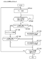
- FIG. 3 is a flowchart showing traffic estimation decoding
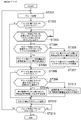
- FIG. 4 is a flowchart showing playback decoding for generating a playback image.
- the traffic estimation decoding process only estimates the traffic to the reference image memory for each picture, and the prediction image is generated by actually reading the reference image from the reference image memory, or the reproduced image is necessary for the subsequent decoding.
- the reference image is not written in the reference image memory. Therefore, access to the reference image memory is not performed and no traffic is generated.
- variable length decoding unit 3 sequentially decodes the input video stream in the order of encoding from the first I2 picture, and sequentially outputs various encoding parameters to the traffic analysis unit 6. (ST101).
- the traffic analysis unit 6 determines whether or not the decoding of the traffic estimation target picture has been completed. When decoding for one picture is completed, the process proceeds to ST103 (ST102).
- the traffic analysis unit 6 identifies the picture type of the decoded traffic estimation target picture (ST103).
- write access to the reference image memory 5 occurs, so write traffic is calculated (ST104).
- the light traffic can be easily calculated if the picture resolution is known.
- read traffic generated when referring to a forward prediction target picture is further calculated based on various coding parameters (ST107).
- ST107 read traffic generated when referring to a forward prediction target picture
- B picture read traffic that occurs when referring to a backward prediction picture is calculated based on various coding parameters (ST106), and further, read traffic that occurs when referring to a forward prediction picture. Are similarly calculated (ST107).
- the traffic analysis unit 6 calculates the specific traffic of the reference image memory 5 generated when each picture is decoded. That is, the traffic for each picture that occurs when the moving picture stream shown in FIG. 2 is reproduced is obtained in advance using the following simple calculation formula.
- ST (X) represents X picture traffic.
- whether or not to compress the reference image is determined as follows, for example. Assume that the I2 picture is decoded for reproduction in the moving picture stream of FIG.
- the pictures that refer to the I2 picture as a reference image are a total of five pictures including B0, B1, B3, B4, and P5 pictures located before and after the I2 picture.
- the traffic to the reference image memory 5 related to each picture must be within the allowable memory bandwidth AW. That is, the following (Expression 11) to (Expression 15) must be satisfied.
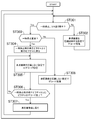
- variable length decoding unit 3 sequentially decodes the input moving picture stream in the coding order from the top I2 picture (ST201). Since the variable length decoding unit 3 operates also in the traffic estimation decoding, as shown in FIG. 5, the decoding process is performed in a time division manner so as to operate exclusively with each other. In addition, in the case of decoding for traffic estimation, access to the reference image memory 5 does not occur at all. Therefore, if the variable-length decoding unit 3 capable of high-speed processing is provided, decoding processing for one picture can be performed in a relatively short time. finish.
- the picture type of the picture to be decoded is identified (ST202). If it is an I picture or a P picture, the reference image compression control unit 8 checks whether or not the traffic estimation has been completed for all the pictures that refer to the decoding target picture (ST203). For example, when the picture to be decoded is an I2 picture, as described above, the pictures that refer to the I2 picture are the B0, B1, B3, B4, and P5 pictures. Therefore, the traffic estimation decoding of these pictures is completed. It is confirmed whether or not. If not completed, it waits until the estimation is completed by the traffic estimation decoding.
- the reference image compression control unit 8 checks whether or not the traffic of all the pictures that refer to the decoding target picture is equal to or smaller than the allowable memory bandwidth AW (threshold) (ST204). For example, when the decoding target picture is an I2 picture, it is confirmed whether or not (Equation 11) to (Equation 15) described above are all satisfied. Alternatively, when the decoding target picture is a P5 picture, ST (B3) ⁇ AW (Expression 16) ST (B4) ⁇ AW (Expression 17) ST (B6) ⁇ AW (Expression 18) ST (B7) ⁇ AW (Equation 19) ST (P8) ⁇ AW (Formula 20) Whether or not all the five conditional expressions are satisfied is confirmed.
- AW allowable memory bandwidth
- the reference image compression control unit 8 compresses the image obtained by decoding the decoding target picture. Without being set, the setting is written to the reference image memory 5, and this setting is temporarily stored (ST205). On the other hand, when it is determined that at least one of the traffics of the picture that refers to the decoding target picture is larger than the allowable memory bandwidth AW (No), the reference image compression control unit 8 obtained by decoding the decoding target picture The setting is such that the image is compressed and written to the reference image memory 5, and this setting is temporarily stored (ST206). Furthermore, the traffic of the picture that refers to the decoding target picture is updated (ST207).
- the traffic of the picture that refers to the decoding target picture also changes, so this traffic is updated.
- the picture to be decoded is an I2 picture
- ST (B1), ST (B3), ST (B4), and ST (P5) also change.
- traffic ST (B3) and ST (B4) of B3 and B4 pictures when the picture to be decoded is a P5 picture, whether the P5 picture is compressed as shown in (Equation 16) and (Equation 17)? It is also used to determine whether or not. Therefore, it is necessary to update the traffic.
- the compression mode (here, whether or not to compress) when the restored image generated by decoding the decoding target picture is stored in the reference image memory 5 is determined. Note that when the decoding target picture is identified as a B picture in ST202, writing to the reference image memory 5 does not occur, so the processing related to the above-described writing setting is skipped and the process proceeds to ST208 described later.
- the picture type of the decoding target picture is identified again (ST208), and when it is a P picture or a B picture, the reference image compression control unit 8 confirms whether or not the picture referenced by the decoding target picture is compressed. Performed (ST209).
- the target reference image is read from the reference image memory 5 and then expanded (ST210).
- the target reference is set. After the image is read from the reference image memory 5, it is set not to expand (ST211). Note that when it is identified as an I picture in ST208, it is not necessary to read the reference image from the reference image memory 5, and therefore the process skips to ST212 described later.
- the reference image is set to be read when the decoding target picture is decoded, and decoding below the slice layer in the picture is activated (ST212).
- the read control unit 9 and the read control unit 10 perform read / write access to the reference image in the reference image memory 5 based on the already determined write / read setting.
- the decoding of one picture of the decoding target picture is completed, it is confirmed whether or not there is a decoding target picture that is not reproduced in the moving image stream (ST213). If there is, the process proceeds to ST201.
- the above-described processing is performed again, and when it does not exist, the processing ends.
- the traffic estimation method is not limited to this. For example, instead of using all of these encoding parameters, traffic may be simply estimated using one or several of them.
- traffic may be simply estimated based on the number of inter macroblocks present in a picture.
- traffic may be simply estimated based on the number of motion vectors extracted for a picture.
- traffic may be simply estimated based on the number of macroblocks for each motion compensation size extracted for a picture.
- each estimated traffic of each picture is compared with the allowable memory bandwidth AW, and compression / non-compression of the decoding target picture is determined from the result of this comparison process.
- the comparison process for determining the compression mode of the reference image is not limited to this.
- a plurality of pictures that refer to the decoding target picture may be used as one unit, and the average value of traffic related to each picture may be compared with the allowable memory bandwidth AW.
- the decoding target picture is an I2 picture
- traffic ST (B0), ST (B1), ST (B3), ST (B4), and ST (P5) of five pictures that refer to the I2 picture The average value and the allowable memory bandwidth AW are compared, and from the comparison result, it is determined whether or not to compress the reference image obtained from the I2 picture.
- the reference image memory 5 is used only for moving image stream reproduction.
- the reference image memory 5 is a memory used for other processes different from moving image stream reproduction. Also good.
- the moving image stream reproduction and other processes are coordinated and controlled so that accesses to the reference image memory 5 do not compete with each other.
- the allowable memory bandwidth AW used for the comparison process may be set to a value obtained by subtracting the traffic required for other processes from the value calculated in the above description.
- only one type of allowable memory bandwidth AW is set, and it is determined whether or not the reference image is compressed by a comparison process between the allowable memory bandwidth AW and traffic.
- the setting of the memory bandwidth AW and the determination of the compression mode are not limited to this.
- a plurality of allowable memory bandwidths AW as predetermined threshold values can be set, and one of a plurality of compression rates is selected by a comparison process between the plurality of allowable memory bandwidths AW and traffic. The method may be used.
- two allowable memory bandwidths AW1 and AW2 are set, the allowable memory bandwidths AW1 and AW2 are compared with the traffic of each picture, and if the traffic of each picture is AW1 or less, decoding is performed. If the target picture is not compressed and is larger than AW1 and smaller than or equal to AW2, the decoding target picture is compressed to 75%, and if it is larger than AW2, the decoding target picture is determined to be compressed to 50% with a higher compression rate.
- independent compression rates may be set for the luminance component and the color difference component.
- the luminance component since the distortion of the luminance component is easily recognized by human eyes, it is more preferable to set the luminance component so that the compression ratio of the luminance component is lower than the compression ratio of the color difference component.
- FIG. 6 is a diagram illustrating a configuration of the image reproduction device 2 according to the second embodiment.
- the same reference numerals as those in FIG. 1 are attached to the same components as those in FIG. 1, and detailed description thereof is omitted here. 6 differs from the first embodiment in that the intermediate buffer memory 202 for temporarily storing the intermediate data decoded by the variable length decoding unit 3 and the writing / writing of the intermediate buffer memory 202 are different.
- An intermediate buffer memory control unit 203 that performs read control is added.
- the traffic estimation decoding and the reproduction decoding are started at different timings, and the variable length decoding unit 3 is operated exclusively.
- the decoding process is performed again to perform the variable length decoding of the same stream for reproduction decoding. Overlap, and extra time is required for decoding for playback.
- the object of the present embodiment is to delete the extra time in the reproduction decoding.
- the traffic estimation decoding is started in advance, and the variable length decoding unit 3 is not only a picture layer but also a slice layer in order to estimate specific traffic for each picture. Decode all up to the macroblock layer.
- the decoded macroblock layer image data (quantization coefficient) is temporarily stored in the intermediate buffer memory 202 as intermediate data. That is, the macroblock layer image data sequentially output from the variable length decoding unit 3 is stored in the intermediate buffer memory 202 by the write control of the intermediate buffer memory control unit 203.
- the video data of the decoding target picture temporarily stored in the intermediate buffer memory 202 is not subjected to variable length decoding again, but the intermediate buffer memory control unit 203 performs read control. Are sequentially read out, and decoding processing is performed using this image data.
- the intermediate data obtained by the decoding process in the traffic estimation decoding is temporarily stored in the intermediate buffer memory 202, and the intermediate data is read from the intermediate buffer memory 202 and reproduced in the reproduction decoding. Generate an image.
- the variable length decoding for each picture can be performed only once, so that the speed of the decoding process for reproduction can be increased.
- the image data (quantization coefficient) generated by variable length decoding is stored in the intermediate buffer memory 202 as intermediate data.
- the intermediate data stored in the intermediate buffer memory 202 is stored in this. It is not limited.
- the binary data after arithmetic decoding is used as intermediate data. It may be stored in the buffer memory 202. Since this binarized data corresponds to the compressed image data (quantization coefficient), the intermediate buffer memory 202 is configured by a relatively small capacity memory by storing this as intermediate data. Can do.
- the reference image memory 5 and the intermediate buffer memory 202 are configured independently of each other.
- the present invention is not limited to this, and the reference image memory 5 and the intermediate buffer memory 202 are configured as a single unit.
- One shared memory may be used. In this case, exclusive control may be performed so that the mutual operations are not affected.
- FIG. 7 is a flowchart showing an image reproduction method according to the third embodiment.
- a specific description will be given of processing in the case where a pause or a frame advance is performed while a moving image stream is being reproduced using the image reproduction method described in the first and second embodiments. .
- the image reproduction methods described in the first and second embodiments compress the reference image only when the traffic to the reference image memory 5 exceeds the allowable memory bandwidth, the distortion time due to the reference image compression generated at the time of decoding is reduced. Propagation can be suppressed as much as possible.
- the reference image compression is frequently performed. This increases the temporal propagation of distortion due to reference image compression.
- distortion due to reference image compression is relatively difficult to notice visually and is not a big problem. For example, when a still image is displayed after being paused The distortion becomes more noticeable when frame-by-frame advance is performed.
- pause or frame advance is instructed during playback of a moving image stream using the image playback method described in the first and second embodiments (ST301). Since frame advance is not performed suddenly during moving image reproduction, it is first determined whether or not a pause is instructed during normal reproduction of a moving image. When the pause is not instructed (No), the moving image stream is reproduced with the setting for performing compression control of the reference image as it is (setting the compression mode according to the traffic of each picture) (ST302). On the other hand, when the pause is instructed (Yes), it is determined whether or not it is immediately after the pause (ST303), and immediately after the pause (Yes), distortion due to the reference image compression is easily noticeable.
- the decoding process is performed again with the setting that the reference image is not compressed (ST305).
- ST305 it is determined whether or not the decoded picture is the same as the reproduced picture at the time of pause (ST306). If not (No), the process proceeds to ST305 and the reference image is not compressed and the next is set. The picture is re-decoded.
- the reproduced image is replaced (ST 307), and the process proceeds to ST 301.
- frame advance is continuously performed after the pause (Yes in ST301, No in ST303)
- the decoding process is performed with the setting that the reference image is not compressed so that the distortion due to the reference image compression does not propagate in time. Perform (ST308).
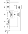
- FIG. 8 is a diagram showing a configuration of an image reproduction device 4 according to the fourth embodiment
- FIG. 9 is a flowchart showing an image reproduction method according to the fourth embodiment.
- the same reference numerals as those in FIG. 1 are given to the same components as those in FIG. 1, and detailed description thereof is omitted here.
- the difference from the first embodiment is that a deterioration degree determination that determines a deterioration degree of a reproduced image caused by propagation of distortion due to reference image compression when a pause or a frame advance occurs.
- the part 402 is added.
- steps common to FIG. 7 are denoted by the same reference numerals as those in FIG. 7, and detailed description thereof is omitted here.
- the flow in FIG. 9 is different from the third embodiment in that step ST401 for determining the degree of degradation of the reproduced image is added when a pause or a frame advance occurs.
- the reproduced picture at that time is referred to
- the temporal propagation of distortion due to image compression is large and small. For example, if an I picture that has no temporal propagation of distortion due to reference image compression is played back and then paused at a relatively early stage, the temporal propagation of distortion due to the reference image compression is small, so that the I picture is traced back. There is no problem even if re-decoding is not performed.
- step ST401 it is determined whether or not the degree of deterioration of the reproduced image decoded from the reproduced picture at the time of pause is large.
- the process returns to the I picture before the playback picture at the time of pause (ST304), and the decoding process is performed again with the setting not to compress the reference picture (ST305).
- pictures are sequentially re-decoded, and when the same picture as the reproduced picture at the time of pause is re-decoded (Yes in ST306), the reproduced image is replaced (ST307).
- step ST401 when the degree of deterioration is relatively small (No in ST401), decoding is then performed with settings that do not compress the reference image (ST308).
- step ST401 compared with the third embodiment, the number of times of performing the re-decoding process that goes back to the I picture can be reduced.
- step ST401 is performed as follows, for example. That is, as a threshold value for determining the degree of degradation of the reproduced image at the time of pause, a temporal distance from the I picture that is acceptable in terms of image quality is set from the setting terminal 7. Then, by comparing the temporal distance from the I picture to the reproduced picture at the time of pause with this threshold value, it is determined whether the degree of deterioration is large or small. Alternatively, instead of or in addition to the temporal distance from the I picture, determination may be made using the number of propagation of distortion due to reference image compression to the reproduced picture at the time of pause.
- the image reproduction method according to each of the above-described embodiments can be used for an imaging system (video system) such as a digital video camera or a digital still camera.
- FIG. 10 shows an example of the configuration of such an imaging system.
- the imaging system of FIG. 10 is a system that uses the image reproduction method according to each embodiment, and the image processing circuit 53 includes an image reproduction unit 100 that can execute the image reproduction method according to each embodiment, and performs image processing. Do.
- the image light incident through the optical system 50 is imaged on the sensor 51 and subjected to photoelectric conversion.
- the electrical signal obtained by the photoelectric conversion is given to the A / D conversion circuit 52 as an analog image signal.
- the A / D conversion circuit 52 converts the input analog image signal into a digital image signal, and then outputs it to the image processing circuit 53.
- Y / C processing, edge processing, image enlargement / reduction, image compression / decompression processing such as JPEG and MPEG, control of an image compressed stream, and the like are performed.
- the image-processed signal is recorded in a medium or transferred via the Internet or the like in the recording / transfer system 54.
- the recorded or transferred signal is reproduced by the reproduction system 55.
- the sensor 51 and the image processing circuit 53 are controlled by a timing control circuit 56, and the optical system 50, the recording / transfer system 54, the reproduction system 55, and the timing control circuit 56 are each controlled by a system control circuit 57.
- the image light from the optical system 50 is photoelectrically converted by the sensor 51 and input to the A / D conversion circuit 52.
- the present invention is not limited to this. Is not to be done.
- an analog video input of an AV device such as a television may be directly supplied to the A / D conversion circuit 52 as an analog image signal.
- the image reproduction method according to each of the above embodiments can be realized by an apparatus including a computer that executes a program for realizing the method. Further, it can be realized by recording a program for realizing the method on a computer-readable recording medium and causing the computer to execute the program recorded on the recording medium.
Landscapes
- Engineering & Computer Science (AREA)
- Multimedia (AREA)
- Signal Processing (AREA)
- Computing Systems (AREA)
- Theoretical Computer Science (AREA)
- Compression Or Coding Systems Of Tv Signals (AREA)
Priority Applications (2)
| Application Number | Priority Date | Filing Date | Title |
|---|---|---|---|
| CN201180044223.2A CN103109535B (zh) | 2010-10-07 | 2011-06-13 | 图像再生方法、图像再生装置、摄像系统及再生系统 |
| US13/832,506 US9386310B2 (en) | 2010-10-07 | 2013-03-15 | Image reproducing method, image reproducing device, image reproducing program, imaging system, and reproducing system |
Applications Claiming Priority (2)
| Application Number | Priority Date | Filing Date | Title |
|---|---|---|---|
| JP2010227774A JP5496047B2 (ja) | 2010-10-07 | 2010-10-07 | 画像再生方法、画像再生装置、画像再生プログラム、撮像システム、および再生システム |
| JP2010-227774 | 2010-10-07 |
Related Child Applications (1)
| Application Number | Title | Priority Date | Filing Date |
|---|---|---|---|
| US13/832,506 Continuation US9386310B2 (en) | 2010-10-07 | 2013-03-15 | Image reproducing method, image reproducing device, image reproducing program, imaging system, and reproducing system |
Publications (1)
| Publication Number | Publication Date |
|---|---|
| WO2012046366A1 true WO2012046366A1 (ja) | 2012-04-12 |
Family
ID=45927377
Family Applications (1)
| Application Number | Title | Priority Date | Filing Date |
|---|---|---|---|
| PCT/JP2011/003347 Ceased WO2012046366A1 (ja) | 2010-10-07 | 2011-06-13 | 画像再生方法、画像再生装置、画像再生プログラム、撮像システム、および再生システム |
Country Status (4)
| Country | Link |
|---|---|
| US (1) | US9386310B2 (cg-RX-API-DMAC7.html) |
| JP (1) | JP5496047B2 (cg-RX-API-DMAC7.html) |
| CN (1) | CN103109535B (cg-RX-API-DMAC7.html) |
| WO (1) | WO2012046366A1 (cg-RX-API-DMAC7.html) |
Families Citing this family (7)
| Publication number | Priority date | Publication date | Assignee | Title |
|---|---|---|---|---|
| TWI551472B (zh) * | 2014-02-20 | 2016-10-01 | 虹光精密工業股份有限公司 | 複製原稿之方法以及使用該方法之事務機 |
| JP2019056971A (ja) | 2017-09-19 | 2019-04-11 | 株式会社東芝 | データ転送回路、データ転送方法及びプログラム |
| WO2019133052A1 (en) | 2017-12-28 | 2019-07-04 | Yang Shao Wen | Visual fog |
| CN109600619A (zh) * | 2018-12-11 | 2019-04-09 | 晶晨半导体(上海)股份有限公司 | 一种解码硬件的分时复用方法 |
| JP7359653B2 (ja) * | 2019-11-06 | 2023-10-11 | ルネサスエレクトロニクス株式会社 | 動画像符号化装置 |
| US11061571B1 (en) * | 2020-03-19 | 2021-07-13 | Nvidia Corporation | Techniques for efficiently organizing and accessing compressible data |
| US12149720B2 (en) * | 2022-06-10 | 2024-11-19 | Qualcomm Incorporated | Storing misaligned reference pixel tiles |
Citations (8)
| Publication number | Priority date | Publication date | Assignee | Title |
|---|---|---|---|---|
| US20030123554A1 (en) * | 2001-12-29 | 2003-07-03 | Kim Eung Tae | Video decoding system |
| JP2005252791A (ja) * | 2004-03-05 | 2005-09-15 | Toshiba Corp | 半導体集積回路装置および画像記録装置 |
| JP2007166323A (ja) * | 2005-12-14 | 2007-06-28 | Matsushita Electric Ind Co Ltd | 画像復号装置、および画像復号方法 |
| JP2007228093A (ja) * | 2006-02-21 | 2007-09-06 | Toshiba Corp | 動き検出装置及び動き検出方法 |
| JP2007306152A (ja) * | 2006-05-09 | 2007-11-22 | Toshiba Corp | 画像復号化装置及び画像復号化方法 |
| JP2009267689A (ja) * | 2008-04-24 | 2009-11-12 | Panasonic Corp | 動画像符号化装置、及び動画像符号化方法 |
| JP2009272948A (ja) * | 2008-05-08 | 2009-11-19 | Toshiba Corp | 動画像復号化装置及び動画像復号化方法 |
| WO2010052837A1 (ja) * | 2008-11-10 | 2010-05-14 | パナソニック株式会社 | 画像復号装置、画像復号方法、集積回路及びプログラム |
Family Cites Families (13)
| Publication number | Priority date | Publication date | Assignee | Title |
|---|---|---|---|---|
| JP3384727B2 (ja) | 1997-11-05 | 2003-03-10 | 三洋電機株式会社 | 画像復号装置 |
| EP0926899A3 (en) | 1997-12-25 | 1999-12-15 | SANYO ELECTRIC Co., Ltd. | An apparatus and process for decoding motion pictures |
| JP3568392B2 (ja) | 1998-06-17 | 2004-09-22 | 三洋電機株式会社 | 動画像復号化装置 |
| JP2000050272A (ja) | 1998-07-31 | 2000-02-18 | Sony Corp | 復号化装置及び方法 |
| JP2000078568A (ja) | 1998-08-28 | 2000-03-14 | Sony Corp | 復号化装置及び方法 |
| JP3398081B2 (ja) * | 1999-03-01 | 2003-04-21 | 三洋電機株式会社 | ディジタルカメラ |
| GB2352350B (en) * | 1999-07-19 | 2003-11-05 | Nokia Mobile Phones Ltd | Video coding |
| KR100353602B1 (en) * | 2002-04-15 | 2002-09-28 | Id Digital Co Ltd | System and method for reproducing motion picture streams regardless of change in playback speed |
| WO2005088983A2 (en) * | 2004-03-08 | 2005-09-22 | Koninklijke Philips Electronics N.V. | Video decoder with scalable compression and buffer for storing and retrieving reference frame data |
| US8050328B2 (en) * | 2005-01-17 | 2011-11-01 | Panasonic Corporation | Image decoding method |
| JP4384130B2 (ja) * | 2006-03-28 | 2009-12-16 | 株式会社東芝 | 動画像復号方法及び装置 |
| TW200812876A (en) | 2006-09-07 | 2008-03-16 | Yao-Sin Liao | Continuous-inflating multi-step gas sealing member and gas valve apparatus |
| US8565310B2 (en) * | 2008-01-08 | 2013-10-22 | Broadcom Corporation | Hybrid memory compression scheme for decoder bandwidth reduction |
-
2010
- 2010-10-07 JP JP2010227774A patent/JP5496047B2/ja active Active
-
2011
- 2011-06-13 WO PCT/JP2011/003347 patent/WO2012046366A1/ja not_active Ceased
- 2011-06-13 CN CN201180044223.2A patent/CN103109535B/zh active Active
-
2013
- 2013-03-15 US US13/832,506 patent/US9386310B2/en active Active
Patent Citations (8)
| Publication number | Priority date | Publication date | Assignee | Title |
|---|---|---|---|---|
| US20030123554A1 (en) * | 2001-12-29 | 2003-07-03 | Kim Eung Tae | Video decoding system |
| JP2005252791A (ja) * | 2004-03-05 | 2005-09-15 | Toshiba Corp | 半導体集積回路装置および画像記録装置 |
| JP2007166323A (ja) * | 2005-12-14 | 2007-06-28 | Matsushita Electric Ind Co Ltd | 画像復号装置、および画像復号方法 |
| JP2007228093A (ja) * | 2006-02-21 | 2007-09-06 | Toshiba Corp | 動き検出装置及び動き検出方法 |
| JP2007306152A (ja) * | 2006-05-09 | 2007-11-22 | Toshiba Corp | 画像復号化装置及び画像復号化方法 |
| JP2009267689A (ja) * | 2008-04-24 | 2009-11-12 | Panasonic Corp | 動画像符号化装置、及び動画像符号化方法 |
| JP2009272948A (ja) * | 2008-05-08 | 2009-11-19 | Toshiba Corp | 動画像復号化装置及び動画像復号化方法 |
| WO2010052837A1 (ja) * | 2008-11-10 | 2010-05-14 | パナソニック株式会社 | 画像復号装置、画像復号方法、集積回路及びプログラム |
Also Published As
| Publication number | Publication date |
|---|---|
| CN103109535A (zh) | 2013-05-15 |
| JP5496047B2 (ja) | 2014-05-21 |
| JP2012085001A (ja) | 2012-04-26 |
| US20130202044A1 (en) | 2013-08-08 |
| US9386310B2 (en) | 2016-07-05 |
| CN103109535B (zh) | 2016-08-17 |
Similar Documents
| Publication | Publication Date | Title |
|---|---|---|
| JP5496047B2 (ja) | 画像再生方法、画像再生装置、画像再生プログラム、撮像システム、および再生システム | |
| EP1775961B1 (en) | Video decoding device and method for motion compensation with sequential transfer of reference pictures | |
| JP2008529412A (ja) | 中間ループフィルタデータを格納するスクラッチパッド | |
| JP2012085001A5 (cg-RX-API-DMAC7.html) | ||
| JP2009267689A (ja) | 動画像符号化装置、及び動画像符号化方法 | |
| KR100192696B1 (ko) | 화상 재생 방식 및 장치 | |
| JP4734168B2 (ja) | 画像復号化装置及び画像復号化方法 | |
| JP4641892B2 (ja) | 動画像符号化装置、方法、及びプログラム | |
| WO2007148619A1 (ja) | 動画像復号装置、復号画像記録装置、それらの方法及びプログラム | |
| KR100681242B1 (ko) | 동영상 복호화 방법, 동영상 복호화 장치 및 이를 가지는시스템 온 칩 시스템 | |
| JP2898413B2 (ja) | 所要メモリ容量の低減化を伴う圧縮ビデオデータ流の復号化及び符号化のための方法 | |
| JP2003230148A (ja) | 画像データ符号化装置 | |
| JP4103276B2 (ja) | 画像記録装置および方法 | |
| CN101065973B (zh) | 解码电路、解码装置及解码系统 | |
| JPH11308618A (ja) | 画像信号処理装置及び方法並びに画像信号再生装置 | |
| JP2000165875A (ja) | メモリ量の少ない動画像解像度変換符号化・復号装置 | |
| WO2010021153A1 (ja) | 動き検出装置 | |
| JPH11136686A (ja) | 復号画像変換回路および復号画像変換装置 | |
| JP4894793B2 (ja) | デコード方法、デコーダ及びデコード装置 | |
| JP2009290387A (ja) | エンコーダ、デコーダ、及び記録再生装置 | |
| JP2000115777A (ja) | 画像処理方法および画像処理装置 | |
| CN101374237A (zh) | 运动图像编码方法和装置以及摄像系统 | |
| KR20050115779A (ko) | 다 해상도 기반의 동 영상 부호화 방법 및 시스템 | |
| JP5061355B2 (ja) | 画像符号化方法、装置およびプログラムならびに画像処理機器 | |
| JPH11122615A (ja) | 画像復号装置 |
Legal Events
| Date | Code | Title | Description |
|---|---|---|---|
| WWE | Wipo information: entry into national phase |
Ref document number: 201180044223.2 Country of ref document: CN |
|
| 121 | Ep: the epo has been informed by wipo that ep was designated in this application |
Ref document number: 11830306 Country of ref document: EP Kind code of ref document: A1 |
|
| NENP | Non-entry into the national phase |
Ref country code: DE |
|
| 122 | Ep: pct application non-entry in european phase |
Ref document number: 11830306 Country of ref document: EP Kind code of ref document: A1 |