WO2012043737A1 - 蓄電パッケージ構造体、電気化学デバイスおよび電気化学モジュール - Google Patents
蓄電パッケージ構造体、電気化学デバイスおよび電気化学モジュール Download PDFInfo
- Publication number
- WO2012043737A1 WO2012043737A1 PCT/JP2011/072418 JP2011072418W WO2012043737A1 WO 2012043737 A1 WO2012043737 A1 WO 2012043737A1 JP 2011072418 W JP2011072418 W JP 2011072418W WO 2012043737 A1 WO2012043737 A1 WO 2012043737A1
- Authority
- WO
- WIPO (PCT)
- Prior art keywords
- package structure
- frame
- power storage
- storage package
- current collecting
- Prior art date
- Legal status (The legal status is an assumption and is not a legal conclusion. Google has not performed a legal analysis and makes no representation as to the accuracy of the status listed.)
- Ceased
Links
Images












Classifications
-
- H—ELECTRICITY
- H01—ELECTRIC ELEMENTS
- H01G—CAPACITORS; CAPACITORS, RECTIFIERS, DETECTORS, SWITCHING DEVICES, LIGHT-SENSITIVE OR TEMPERATURE-SENSITIVE DEVICES OF THE ELECTROLYTIC TYPE
- H01G11/00—Hybrid capacitors, i.e. capacitors having different positive and negative electrodes; Electric double-layer [EDL] capacitors; Processes for the manufacture thereof or of parts thereof
- H01G11/10—Multiple hybrid or EDL capacitors, e.g. arrays or modules
- H01G11/12—Stacked hybrid or EDL capacitors
-
- H—ELECTRICITY
- H01—ELECTRIC ELEMENTS
- H01M—PROCESSES OR MEANS, e.g. BATTERIES, FOR THE DIRECT CONVERSION OF CHEMICAL ENERGY INTO ELECTRICAL ENERGY
- H01M50/00—Constructional details or processes of manufacture of the non-active parts of electrochemical cells other than fuel cells, e.g. hybrid cells
- H01M50/10—Primary casings; Jackets or wrappings
- H01M50/102—Primary casings; Jackets or wrappings characterised by their shape or physical structure
- H01M50/105—Pouches or flexible bags
-
- H—ELECTRICITY
- H01—ELECTRIC ELEMENTS
- H01G—CAPACITORS; CAPACITORS, RECTIFIERS, DETECTORS, SWITCHING DEVICES, LIGHT-SENSITIVE OR TEMPERATURE-SENSITIVE DEVICES OF THE ELECTROLYTIC TYPE
- H01G11/00—Hybrid capacitors, i.e. capacitors having different positive and negative electrodes; Electric double-layer [EDL] capacitors; Processes for the manufacture thereof or of parts thereof
- H01G11/14—Arrangements or processes for adjusting or protecting hybrid or EDL capacitors
- H01G11/18—Arrangements or processes for adjusting or protecting hybrid or EDL capacitors against thermal overloads, e.g. heating, cooling or ventilating
-
- H—ELECTRICITY
- H01—ELECTRIC ELEMENTS
- H01G—CAPACITORS; CAPACITORS, RECTIFIERS, DETECTORS, SWITCHING DEVICES, LIGHT-SENSITIVE OR TEMPERATURE-SENSITIVE DEVICES OF THE ELECTROLYTIC TYPE
- H01G11/00—Hybrid capacitors, i.e. capacitors having different positive and negative electrodes; Electric double-layer [EDL] capacitors; Processes for the manufacture thereof or of parts thereof
- H01G11/74—Terminals, e.g. extensions of current collectors
- H01G11/76—Terminals, e.g. extensions of current collectors specially adapted for integration in multiple or stacked hybrid or EDL capacitors
-
- H—ELECTRICITY
- H01—ELECTRIC ELEMENTS
- H01G—CAPACITORS; CAPACITORS, RECTIFIERS, DETECTORS, SWITCHING DEVICES, LIGHT-SENSITIVE OR TEMPERATURE-SENSITIVE DEVICES OF THE ELECTROLYTIC TYPE
- H01G11/00—Hybrid capacitors, i.e. capacitors having different positive and negative electrodes; Electric double-layer [EDL] capacitors; Processes for the manufacture thereof or of parts thereof
- H01G11/78—Cases; Housings; Encapsulations; Mountings
- H01G11/82—Fixing or assembling a capacitive element in a housing, e.g. mounting electrodes, current collectors or terminals in containers or encapsulations
-
- Y—GENERAL TAGGING OF NEW TECHNOLOGICAL DEVELOPMENTS; GENERAL TAGGING OF CROSS-SECTIONAL TECHNOLOGIES SPANNING OVER SEVERAL SECTIONS OF THE IPC; TECHNICAL SUBJECTS COVERED BY FORMER USPC CROSS-REFERENCE ART COLLECTIONS [XRACs] AND DIGESTS
- Y02—TECHNOLOGIES OR APPLICATIONS FOR MITIGATION OR ADAPTATION AGAINST CLIMATE CHANGE
- Y02E—REDUCTION OF GREENHOUSE GAS [GHG] EMISSIONS, RELATED TO ENERGY GENERATION, TRANSMISSION OR DISTRIBUTION
- Y02E60/00—Enabling technologies; Technologies with a potential or indirect contribution to GHG emissions mitigation
- Y02E60/10—Energy storage using batteries
Definitions
- the present invention relates to a power storage package structure, an electrochemical device, and an electrochemical module.
- a positive electrode and a negative electrode are arranged so that different poles face each other, and the stacked electrode structure is put in a package in a so-called 99-fold manner.
- a structure for injecting an electrolytic solution is known (for example, Patent Document 1).
- Such ninety-nine folds are excellent in that an electrode that can be miniaturized can be easily formed because a structure in which electrodes adjacent to each other serve as other poles can be formed by bending one electrode. .
- a film 120 is used for a flexible outer container, and the electrode structure 110 is accommodated inside the outer container.
- the sealing portion S is provided on the outer peripheral portion for sealing, and the electrode extraction portion 111c is provided at the sealing end of the outer container.
- P is an outer peripheral end of the outer container, that is, a package line.
- a hard container is used as an outer container, an electrode structure is accommodated in the outer container, and an electrode take-out portion is provided on the upper peripheral edge of the outer container.
- the power storage device of Patent Document 1 proposes a folded structure of an electrode body that can be accommodated in a package without waste. Absent.
- the electrochemical device of Patent Document 2 has an advantage of being lightweight because a film is used for a flexible outer container, but it is necessary to provide a seal portion on the outer peripheral portion of the outer container and perform sealing. Therefore, it is necessary to increase the distance from the edge of the electrode structure to the outer periphery of the outer container. In addition, it is necessary to separately provide an electrode extraction part at the sealed end of the outer container, and there is a problem that workability is poor when a plurality of such electrochemical devices are stacked and interconnected.
- any of the electricity storage device of Patent Document 1, the electrochemical device of Patent Document 2, and the electricity storage element of Patent Document 3 has a dead space, resulting in a low energy density per volume.
- the increase in the energy density per volume is a major problem because it cannot avoid the increase in size.
- the present invention has been made in view of the above circumstances, and an object thereof is to provide an energy storage package structure, an electrochemical device, and an electrochemical module that have a high energy density per volume and can be miniaturized.
- the present invention has found that the above-described problems can be solved by the following electricity storage package structure, electrochemical device, and electrochemical module.
- a frame-shaped portion made of a pair of insulators opposed to each other via a joint surface;
- a lid that is attached to the opening of the frame-shaped portion and forms a sealed structure;
- a power storage package structure comprising: an extraction electrode formed on at least one outer wall of the pair of frame-like portions.
- the power storage package structure according to [1] The electrical storage package structure, wherein the extraction electrode includes a conductor layer extending from the joint surface to an outer wall of the frame-like portion.
- the power storage package structure according to [1] or [2], The power storage package structure has opposing main surfaces and four side surfaces, A power storage package structure having an extraction electrode on each of four side surfaces.
- the power storage package structure according to any one of [1] to [3], The power storage package structure has opposing main surfaces, A power storage package structure in which a heat sink is mounted on at least one of the main surfaces.
- the power storage package structure according to [4], The heat dissipation plate is a power storage package structure that is joined to the frame-shaped portion and constitutes at least one of the lids.
- the power storage package structure according to [4] or [5] The heat dissipation plate is a power storage package structure that protrudes outward from the surface of the frame-shaped portion.
- the electrode plate laminated through the separator in the electricity storage package structure according to any one of [1] to [6] is sealed together with the electrolyte solution, The electrochemical device, wherein the electrode plate is sandwiched between the pair of frame-like portions such that a current collecting tab derived from the electrode plate is in contact with the conductor layer.
- the electrochemical device according to [7] The current collecting tab is an electrochemical device that is bent along the outer wall of the frame-like portion and joined to the conductor layer.
- the current collection package structure of this invention rather than the case of either the electrochemical device of patent document 2, and the electrical storage element of patent document 3 Since the current collecting tab can be shortened and the volume of the entire package structure including the current collecting tab is reduced, the size can be reduced. As a result, the energy storage package structure of the present invention can increase the energy density [energy amount per volume].
- the current collector tab can be connected to the extraction electrode using a conductive paste, and can be electrically connected by partial heating by laser irradiation, welding, brazing, soldering, etc. Connection processing can be performed simultaneously.
- the electricity storage package structure of the present invention by using ceramic for the frame-like portion and forming the extraction electrode, a heat flow can be formed through the electrolytic solution and the current collecting tab, and the heat dissipation can be improved. Furthermore, heat dissipation can be further improved by using a ceramic having good thermal conductivity such as aluminum nitride or alumina for the frame-like portion.
- the extraction electrode can be formed by using a resin base material for the frame portion and using a metal foil such as a copper foil, a conductive thin film or a thick film.
- a resin substrate for the frame-shaped portion it is possible to form an exterior container that is easy to shape and has high dimensional accuracy.
- the extraction electrodes are provided on the four side surfaces, current can be efficiently collected from the tabs led out from the electrodes in four directions. Furthermore, since the extraction electrode is formed on at least one outer wall of the pair of frame-shaped portions, current can be collected efficiently without increasing the size of the power storage unit. Furthermore, in the electricity storage package structure of the present invention, a package structure with high heat dissipation can be formed by attaching a heat sink to at least one of the main surfaces of the package structure. Further, by forming the heat radiating plate so as to constitute at least one of the lids by being joined to the frame-shaped portion, it is possible to provide a power storage package structure with higher heat radiating efficiency and excellent heat radiating properties. It becomes possible.
- the heat dissipation can be further improved by configuring the heat dissipation plate to protrude outward from the surface of the frame-shaped portion. Therefore, sufficient heat dissipation can be obtained even when the power storage package structure of the present invention is stacked and used.
- the electricity storage package structure of the present invention is applied to the extraction electrode in which the current collection tab led out from the electrode plate is formed on at least one outer wall of the pair of frame-shaped portions.
- the current collecting tab can be made small and highly efficient by bending the current collecting tab along the outer wall of the frame-shaped portion and joining the current collecting tab to the conductor layer.
- the electrochemical module of the present invention it is possible to provide a smaller and more excellent electrochemical module by mounting the connector portion for external connection on the extraction electrode of the electrochemical device of the present invention. It becomes possible.
- the current collecting tab that is, the lead portion drawn out from the electrode may be disposed at any portion of the electrode end face. And it is desirable to form the joint surface following the extraction electrode of the electricity storage package structure in accordance with each lead portion. The distance between the joint surface and each lead portion is preferably shortened. By doing so, a space for routing the lead portion is not required, and the size of the storage container can be further reduced. According to the electrochemical module of the present invention, since the electrode and the external terminal can be connected via the thin extraction electrode and the current collecting tab arranged on the inner side surface of the electricity storage package structure, the volume of the package structure can be increased. On the other hand, the ratio of the volume of the power storage unit can be increased.
- FIG. 1 is an exploded perspective view of a storage package structure for a lithium ion capacitor according to a first embodiment of the present invention
- the figure which shows the electrode structure used for the lithium ion capacitor of Embodiment 1 of this invention (a) is the perspective view which showed the electrode structure typically, (b) is the upper surface seen from the positive electrode plate of the electrode structure (C) is a top view of the electrode structure as viewed from the negative electrode plate, (d) is a diagram showing the outer shape of the positive electrode plate and the negative electrode plate before folding.
- (A) And (b) is a figure which shows the formation surface of the positive electrode in the lithium ion capacitor of the modification 1 of this invention, and the formation surface of a negative electrode (A) And (b) is a figure which shows the formation surface of the positive electrode in the lithium ion capacitor of the modification 2 of this invention, and the formation surface of a negative electrode (A) And (b) is a figure which shows the formation surface of the positive electrode in the lithium ion capacitor of the modification 3 of this invention, and the formation surface of a negative electrode
- the exploded perspective view of the electrical storage package structure used for the lithium ion capacitor of the modification 3 of this invention The perspective view which shows the external appearance of the lithium ion capacitor of Embodiment 2 of this invention (A) And (b) is the exploded perspective view of the electrical storage package structure of the lithium ion capacitor of Embodiment 2 of this invention Explanatory drawing which shows the manufacturing process of the lithium ion capacitor of Embodiment 2 of this invention.
- the figure which shows the cross section of the electrical storage package structure of the modification 4 of this invention The figure which shows the cross section of the electrical storage package structure of the modification 5 of this invention
- the figure which shows the cross section of the electrical storage package structure of the modification 6 of this invention The partially expanded perspective view which shows the electrode structure of the modification 3 of this invention
- the perspective view which shows the electrical storage module of Embodiment 3 of this invention It is a figure which shows the component of the electrical storage module of Embodiment 3 of this invention, (a) is a perspective view of a lithium ion capacitor, (b) is a perspective view of an external current collection package.
- the figure which shows the assembly process of the electrical storage module of Embodiment 3 of this invention The figure which shows the lamination type electrical storage module of Embodiment 4 of this invention It is a figure which shows the structural member of the laminated
- FIG. 1 is a perspective view showing the appearance of a lithium ion capacitor that is an electrochemical device according to Embodiment 1 of the present invention
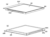
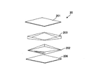
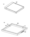
- FIG. 2 is an exploded perspective view of a storage package structure of the lithium ion capacitor of the present invention
- FIG. An upper frame part and (b) show a lower frame part.
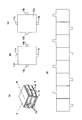
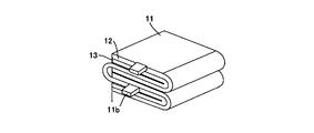
- 3 is a perspective view schematically showing an electrode structure of a lithium ion capacitor of the present invention
- FIG. 4 is an explanatory view showing a manufacturing process of the lithium ion capacitor of the present invention
- FIG. 1 is a perspective view showing the appearance of a lithium ion capacitor that is an electrochemical device according to Embodiment 1 of the present invention
- FIG. 2 is an exploded perspective view of a storage package structure of the lithium ion capacitor of the present invention
- FIG. An upper frame part and (b) show a lower frame part.
- 3 is a perspective view schematically showing an electrode structure of a lithium ion capacitor of the present invention
- FIG. 4 is an
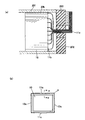
- FIG. 1 It is a figure which shows the junction part of an electrode structure, (a) is a principal part expanded sectional view which shows the collector part of a positive electrode, (b) is a principal part expanded sectional view which shows the collector part of a negative electrode, FIG. It is a front view of the lithium ion capacitor of the present invention.
- 3A is enlarged in the thickness direction (Z1-Z2) of the lithium ion capacitor of the present invention of FIG. 1 in order to explain how it is folded.
- a power storage package structure 20 of a lithium ion capacitor has a pair of frame-shaped portions (a lower frame portion 202 and an upper frame portion 203) that face each other through a joint surface. And a lid that is attached to an opening of the frame-like portion (lower frame portion 202, upper frame portion 203) to form a sealed structure, and a pair of frame-like portions (lower frame portion 202, upper frame portion) 203) and an extraction electrode 204 formed on the outer wall.
- a pair of frame portions (lower frame portion 202, upper frame portion 203) is formed of an alumina molded body, and a conductor layer pattern is formed to constitute the extraction electrode 204.
- This lid is made of a copper foil whose inner side is insulated, and constitutes heat sinks 201 and 206.
- no conductor layer made of copper foil is formed on the joint surfaces 202S and 203S between the lower frame portion 202 and the upper frame portion 203 constituting the pair of frame-shaped portions.
- the conductor layer is led out to the outer wall of the frame-like part (the lower frame part 202 and the upper frame part 203) to constitute the extraction electrode 204 (the positive electrode extraction electrode 204a and the negative electrode extraction electrode 204b).
- this heat radiating plate has heat radiating pieces 201F and 206F protruding outward from the surface of the frame-like portion (lower frame portion 202, upper frame portion 203).
- FIG. 3A shows a perspective view
- FIGS. 3B and 3C show the AA plane and the BB plane of FIG. 3A.
- the electrode structure 10 is accommodated.
- a positive electrode plate 11 is overlapped with a negative electrode plate 13 via a separator 12 and is folded.
- FIG. 3A shows a laminated structure for three layers, the number of layers of the laminated structure is not limited. Generally, it is often used as a laminated structure of about 10 layers, and any number of layers may be stacked.
- the positive electrode plate and the negative electrode plate of the electrode structure 10 are shown in FIG.
- the current collecting tabs 11b of the positive electrode plate 11 are led out in parallel to the fold direction of the positive electrode plate itself, one pair at a position facing each other for each layer.
- the current collecting tabs 13b of the negative electrode plate 13 are led out in parallel to the fold direction of the negative electrode plate itself, one pair at a position facing each other for each layer.
- the positive electrode plates and the negative electrode plates are alternately stacked via the separators, and the shape can be laminated in a rectangular parallelepiped or a cube, so that a capacitor having a large capacity without waste of space can be provided.
- the current collecting tabs are alternately led out from the respective layers and connected to the extraction electrode, so that the internal resistance can be reduced.
- the positive electrode plate 11 includes a main body portion 11a, a current collecting tab 11b, and an external current collecting lead portion 11c. And in this current collection tab 11b and the external current collection lead part 11c, the core material which consists of an aluminum plate is exposed, and the positive electrode active material is apply
- a positive electrode active material mainly composed of spinel type lithium manganate represented by LiMnO 4 is mixed with a fluororesin binder and used as a positive electrode mixture.
- the current collecting tab 11b is formed integrally with the main body 11a, and the tab is formed in the lateral direction of the electrode before folding.
- the current collection tab which formed only the main-body part 11a with the continuous strip
- the positive electrode current collecting tab 11b may be led out in one direction perpendicular to the longitudinal direction of the strip. The tip of the current collecting tab 11b is joined to the extraction electrode as the external current collecting lead portion 11c.
- this negative electrode plate 13 is also composed of a main body portion 13a, a current collecting tab 13b, and an external current collecting lead portion 13c, like the positive electrode plate. And as shown in FIG.3 (c), in this current collection tab 13b and the external current collection lead part 13c, the core material which consists of a copper plate is exposed, and a negative electrode active material is both surfaces of a core material in a main-body part. Has been applied.
- a negative electrode active material that can insert and desorb lithium ions, a rubber-based binder, and water are mixed to form a negative electrode mixture, which is applied to the core material.
- the negative electrode active material a carbon-based material capable of inserting and desorbing lithium ions, such as graphite, carbon black, coke, glassy carbon, carbon fiber, or a fired body thereof, is preferable.
- the tip of the current collecting tab 13b is joined to the extraction electrode as an external current collecting lead portion 13c.
- the positive electrode plate and the negative electrode plate were folded into ninety-nine folds via a polypropylene separator 12 to obtain an electrode structure 10. That is, the positive electrode plate and the negative electrode plate are formed as strips, and are alternately folded through the separators 12 in directions orthogonal to each other.
- an electrolytic solution mainly composed of ethylene carbonate (EC) and propylene carbonate (PC) is used.
- the current collecting tabs 11b and 13b are led out in the vicinity of the center of the pair, one pair on each opposite side of the quadrangle constituting the folded electrode structure (FIG. 3B).
- an extraction electrode 204 (which is sandwiched between the joint surfaces 202S and 203S of the divided portion of the electricity storage package structure 20 and is bent along the outer wall of the frame-shaped portion, and made of a conductor layer formed on the outer wall.
- the positive electrode extraction electrode 204a and the negative electrode extraction electrode 204b) are joined.
- an enlarged perspective view of the main part of the current collector tab 11 b of the positive electrode and an enlarged sectional view of the main part of the positive electrode 11 in FIG. It is led out along the joint surfaces 202S and 203S between the frame part 202 and the upper frame part 203, and joined to the extraction electrode 204 formed by applying the aluminum paste 207 and the Ag paste 208 to the outer wall part. Yes.
- the joint between the current collecting tab 11b and the external current collecting lead portion 11c and the extraction electrode 204 is joined with good adhesion by heat of fusion.
- an enlarged cross-sectional view of the main part of the negative electrode 13, the negative electrode current collecting tab 13 b includes a lower frame portion 202 of the pair of frame portions (202, 203) from the electrode structure 10.
- the junction between the current collecting tab 13b and the external current collecting lead 13c and the negative electrode take-out electrode 204b is bonded with good adhesion by heat of fusion.
- a frame-shaped part is formed by forming a molded body by compression molding using alumina as a material and firing it. Further, a positive electrode extraction electrode 204a and a negative electrode extraction electrode 204b are respectively formed on the outer wall of the frame-shaped portion. In the present embodiment, as shown in FIGS. 2A and 2B, the positive electrode extraction electrode 204a and the negative electrode extraction electrode 204b are provided on the outer wall of the frame-shaped portion composed of the upper frame portion 203 and the lower frame portion 202. Each pair is formed opposite to each other.
- the positive electrode side as shown in FIG.
- an aluminum paste is applied to form an aluminum layer 207 and covered with an Ag paste 208 to form a positive electrode extraction electrode 204a.
- a thin film having a three-layer structure of Al, Ag, and Cu that is, a three-layer film 209 is formed by sputtering and covered with Ag paste 208 to form a negative electrode take-out electrode 204b.
- the heat sinks 201 and 206 made of copper foil are joined to the upper frame portion 203 and the lower frame portion 202 formed as described above.
- FIG. 3A is a perspective view schematically showing the electrode structure
- FIG. 3B is a top view seen from the positive electrode plate of the electrode structure
- FIG. 3C is a top view seen from the negative electrode plate of the electrode structure
- FIG. 3D is a diagram showing the outer shape of the positive electrode plate and the negative electrode plate before folding.
- an aluminum plate is punched, and as shown in FIG. 3D, a strip-shaped core material having a main body portion 11a, a current collecting tab 11b, and an external current collecting lead portion 11c is formed. It is formed continuously in layers.
- the positive electrode active material described above is applied to both surfaces of the core material.
- the positive electrode plate 11 shall apply
- a copper plate is punched, and this negative electrode plate 13 is also provided with a main body 13a, a current collecting tab 13b, and an external current collecting lead, like the positive electrode plate shown in FIG.
- a belt-like core material having a portion 13c is continuously formed for 10 layers.
- the negative electrode active material described above is applied to both surfaces of the core material.
- it is assumed that the negative electrode plate is coated with a negative electrode active material.
- FIG. 3A shows a perspective view of the electrode structure 10 formed in this way.
- the positive electrode plate 11 is overlapped with the negative electrode plate 13 via the separator 12 and folded.
- a top view of the folded positive electrode plate is shown in FIG.
- the top view seen from the negative electrode plate is shown in FIG.
- the current collecting tabs 11b of the positive electrode plate 11 are led out in parallel to the direction of the folds of the positive electrode plate, one by one at the mutually opposing positions for each layer, and the current collecting tabs of the negative electrode plate 13 13b is led out in parallel to the direction of the folds of the negative electrode plate, one by one at the position alternately facing each other.
- the electrode structure 10 is housed in the lower frame portion 202 of the frame-shaped portion of the power storage package structure 20, and the current collecting tabs 11 b and 13 b are respectively connected to the joint surfaces of the sides. It is installed so that it abuts. And the current collection tabs 11b and 13b are inserted
- the current collector tab 11 b is sandwiched between the portions corresponding to the central portion on each side, as shown in FIG.
- the external current collecting lead portion 11c at the tip of the current collecting tab 11b is joined to the extraction electrode 204 constituting the positive electrode extraction electrode 204a.
- the current collecting tab 13b is sandwiched between portions corresponding to the central portion on each side, and the external current collecting at the tip of the current collecting tab 13b.
- the electric lead portion 13c is joined to the extraction electrode 204 constituting the negative electrode extraction electrode 204b. Therefore, the electrical connection between the current collecting tab 13b and the negative electrode take-out electrode 204b and the physical connection between the joint surfaces of the pair of frame portions are sufficient.
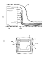
- FIG. 7A shows an enlarged cross-sectional view of the main part of the lithium ion capacitor of the present invention
- FIG. 7B shows an enlarged top view of the main part of the lithium ion capacitor of the present invention.
- the drawing distance of the current collecting tab can be minimized, and not only the size can be reduced, but also the current collecting tab can be reduced. Resistance loss due to the routing of the electric tab is reduced.
- the power storage package of the present embodiment since no film is used for the package structure that is an exterior container, unlike the conventional power storage device shown in Patent Document 2, there is no need to provide a sealing region on the outer periphery, and the power storage package of the present embodiment According to the structure, the lead-out portion of the current collecting tab can be shortened.
- the power storage package structure of the present embodiment is configured so that the current collecting tab is sandwiched between the pair of frame-shaped portions, the conventional power storage device shown in Patent Document 1 is shown in Patent Document 2.
- the current collecting tab can be made shorter than in any of the conventional electrochemical devices.
- the power storage package structure since the volume occupied by the entire package structure including the current collector tabs 11b and 13b is reduced, the power storage package structure can be reduced in size.
- the energy density (the amount of energy per volume) can be increased.
- the volume occupied here is not the actual volume of the package structure, but corresponds to the product of the thickness, length, and width of the package structure.
- ceramic is used for the frame-like portion, and the extraction electrode is formed using copper foil, thereby forming a heat flow through the electrolytic solution and the current collecting tab, thereby improving heat dissipation. It can. And since alumina is used for a frame-shaped part, heat conductivity is favorable and can also improve heat dissipation.
- the ceramic constituting the frame portion is not limited to alumina, and other insulating ceramics such as aluminum nitride can be applied. By using aluminum nitride, the thermal conductivity is further improved.
- connection between the take-out electrode and the current collecting external lead can be easily performed by bringing them into contact with each other and heating and fusing the surfaces. Bonding is also possible by applying a metal paste such as silver paste or copper paste to the joint and curing it. Furthermore, in the present embodiment, since the heat sinks 201 and 206 are mounted on the main surface of the package structure, a package structure with high heat dissipation can be formed.
- the current collecting tab is bent along the outer wall of the frame-like portion and joined to the conductor layer, so that the area to be joined is increased, sufficient joining is achieved, and the size and height are increased. It can be efficiency.
- Mode 1 In the first embodiment, as shown in FIGS. 6A and 6B, the extraction electrode is formed on the lower frame portion on the positive electrode formation surface, and the extraction electrode is formed on the upper frame portion on the negative electrode formation surface. .
- the external current collecting lead portion 11c at the tip of the positive current collecting tab 11b is bent downward and the external current collecting lead portion 13c at the tip of the negative current collecting tab 13b is bent upward and joined.
- the current collecting tab is bent in the same direction. In this case, it is only necessary to form the extraction electrode only on one frame-like portion.
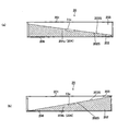
- FIGS. 8A and 8B show a positive electrode formation surface and a negative electrode formation surface in the lithium ion capacitor of Modification 1 of the present invention.
- the side surface of the lower frame portion 202 is made larger than the side surface of the upper frame portion 203, and the lower frame portion is formed on the positive electrode forming surface and the negative electrode forming surface.
- An extraction electrode is formed, and the external current collecting leads 11c and 13c at the tips of the positive and negative current collecting tabs 11b and 13b are bent and joined downward. In this case, the joining area can be increased, and the current collecting tabs have the same bending direction, so that simultaneous processing is possible and mounting workability is improved.
- the electrode structure 10 is not limited to such a ninety-nine fold structure, and can be applied to other electrode structures such as a laminated body and a wound structure.
- the current collecting tab 13b is sandwiched between the lower frame portion 202 and the middle frame portion 210 on the negative electrode forming surface, and the external current collecting lead portion 13c at the tip of the current collecting tab 13b of the negative electrode is bent downward to form the lower frame. It contacts the negative electrode take-out electrode 204b formed in the portion 202.
- the middle frame portion 210 is sandwiched so that the positive electrode and the negative electrode can be taken out and the reliability is improved. Since other parts including the electrode structure 10 are the same as those in the first embodiment, the description thereof is omitted here. However, it is needless to say that the electrode structure is not limited to such a wound structure, and can be applied to other electrode structures such as a laminated body and a ninety-nine fold structure.
- FIGS. 10A and 10B show a positive electrode formation surface and a negative electrode formation surface in a lithium ion capacitor of Modification 3 of the present invention.
- the structure in which the frame-like portion is horizontally divided into upper and lower parts or three parts has been described.
- the third modified example is obliquely divided into two parts.
- the extraction electrode is formed on the lower frame portion on the positive electrode forming surface
- the extraction electrode is formed on the upper frame portion on the negative electrode forming surface
- the external current collecting lead portion 11c at the tip of the positive current collecting tab 11b is downward.
- the external current collecting lead 13c at the tip of the negative current collecting tab 13b is bent upward and joined.
- FIG. 11 is an exploded perspective view of a power storage package structure used in the lithium ion capacitor of Modification 3 of the present invention.
- the connection between the current collecting tab and the extraction electrode is made between the conductor layer formed on the outer wall of the frame-shaped portion, but in the second embodiment, The conductor layer is formed from the joining surfaces 202S and 203S to the outer wall, the connection between the current collecting tab and the extraction electrode is realized by the joining surface, and the current collecting tab is not exposed to the outer wall. (See FIG. 12). That is, as shown in FIGS. 12 and 13, the lithium ion capacitor power storage package structure 20 according to the second embodiment of the present invention forms a pair of frame-like portions facing each other through the joint surfaces 202S and 203S.
- the upper frame portion 203 and the lower frame portion 202 are formed of a frame-shaped portion made of aluminum nitride, and a conductor layer pattern extending from the joint surface to the outer wall is crimped to form an extraction electrode 204.
- a conductor layer made of copper foil is formed on the joint surfaces 202S and 203S between the upper frame portion 203 and the lower frame portion 202 constituting the pair of frame-shaped portions, and the joint surfaces are formed. And is led out to the outer walls of the upper frame portion 203 and the lower frame portion 202 to constitute the extraction electrode 204.
- the current collecting tab is short, abuts with the extraction electrode only at the joint surface, and does not reach the outer walls of the upper frame portion 203 and the lower frame portion 202. This is a feature.
- Other configurations are the same as those of the first embodiment of the present invention.
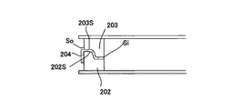
- FIG. 15 sectional drawing of the electrical storage package structure of the modification 4 of this invention is shown.
- the surface from the inner side surface Si to the outer side surface So serving as the outer wall has a step structure in the joining surfaces 202S and 203S of the frame-shaped portion. This is different from the first and second embodiments.
- the configuration of the fourth modification since the surface from the inner side surface Si to the outer side surface So serving as the outer wall has a step structure in the joint surfaces 202S and 203S of the frame-shaped portion, the area of the joint surface is increased.
- FIG. 16 sectional drawing of the electrical storage package structure of the modification 5 of this invention is shown.
- the main surface is that the surface from the inner side surface Si to the outer side surface So serving as the outer wall has a gentle step structure on the joint surfaces 202S and 203S of the frame-like portion.
- the conductor layer is formed on the gentle joint surface. Cutting can be prevented.
- the electrical connectivity is good, and the area of the joint surface can be increased. Further, since the contact area with the current collecting tab can be increased, the connectivity with the current collecting tab (not shown here) can be improved. Furthermore, good bonding can be obtained.
- FIG. 17 sectional drawing of the electrical storage package structure of the modification 6 of this invention is shown.
- the surface of the joining surface 202S, 203S of the frame-shaped portion has an inclined structure from the inner side surface Si to the outer side surface So that is the outer wall. This is a point different from Modifications 4 and 5.
- the conductor layer is formed on the gentle joining surface. Can be prevented.
- the electrical connectivity is good, the area of the joint surface can be increased, and the connectivity with the current collecting tab (not shown here) can be enhanced. Furthermore, good bonding can be obtained.
- FIG. 19 is a view showing the electrode structure described in the first embodiment and the modification for comparison.
- FIG. 18 is a view showing the electrode structure described in the first embodiment and the modification for comparison.
- the electrode structure has a ninety-nine fold structure as shown in FIG. 18 has been described.
- a fold structure is used as shown in FIG. Is also effective.
- the positive electrode plate and the negative electrode plate constituting the positive electrode and the negative electrode are the same as in Embodiments 1 and 2 of the present invention, and 11b and 13b are current collecting tabs.
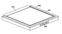
- FIG. 20 is a perspective view showing a power storage module according to Embodiment 3 of the present invention.
- FIG. 21 shows components of the power storage module according to Embodiment 3 of the present invention, (a) is a perspective view showing a single cell of a lithium ion capacitor 100 as an electrochemical device, and (b) shows an external current collection package 300. It is a perspective view shown.
- FIG. 20 is a perspective view showing a power storage module according to Embodiment 3 of the present invention.
- FIG. 21 shows components of the power storage module according to Embodiment 3 of the present invention, (a) is a perspective view showing a single cell of a lithium ion capacitor 100 as an electrochemical device, and (b) shows an external current collection package 300. It is a perspective view shown.
- FIG. 22 is a diagram illustrating an assembly process of the power storage module according to the third embodiment of the present invention.
- a single cell of an lithium ion capacitor 100 that is an electrochemical device and an external current collection package 300 are prepared, and an extraction electrode 204 of the lithium ion capacitor 100 is attached to the external current collection package 300,
- the power storage module can be easily connected.
- an electric plug 320 is used as a connector portion for external connection. Therefore, external connection is easy.
- the external current collection package 300 is made of a frame and constitutes a current collection frame having a current collection function. As shown in FIG. 21B, a main body 301 made of a resin current collecting frame, a positive current collecting spring 311 and a negative current collecting spring 313 formed on the inner wall, and an electric plug 320 for external connection are provided. It has. This electric plug is electrically connected to the positive current collecting spring 311 and the negative current collecting spring 313 in the main body 301.
- a single cell of the lithium ion capacitor 100 is attached to the external current collection package 300, and the power storage module shown in FIG. 20 is completed. Since the configuration of the single cell of the lithium ion capacitor 100 is the same as that of the first embodiment of the present invention, the description thereof is omitted here.
- the external current collecting package can be formed very easily just by mounting, no special wiring is required, and connection work as a power storage module is performed by an electric plug as a connector portion. It can be very simple.
- Embodiment 4 With reference to FIG. 23 thru
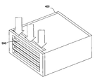
- four power storage modules which are the electrochemical modules described in the third embodiment of the present invention, are stacked as a power storage module unit 500 and mounted on a module package 400 as a current collecting package. This constitutes a capacity storage module.
- FIG. 23 shows the stacked power storage module according to Embodiment 4 of the present invention.
- FIG. 24 shows components of the stacked power storage module according to Embodiment 4 of the present invention, (a) is a perspective view of the power storage module unit 500, and (b) is a perspective view of the module package 400.
- the power storage module unit 500 constitutes one cell of an electrochemical device.
- the module package 400 has module current collectors 431 and 433 on the inner wall, and the module current collectors 431 and 433 are led out to the outer wall of the main body 430.
- the electrical plug 320 which is a connector portion can be easily mounted by mounting it on the module current collectors 431 and 433 formed on the inner wall of the module package 400.
- the module current collectors 431 and 433 constitute a socket portion that engages with the connector portion.
- the module package 400 includes a main body 430 made of a resin current collecting frame, module current collectors 431 and 433 formed on the inner wall, and a partition plate. 434.
- the module current collectors 431 and 433 are electrically connected to the positive current collecting spring 311 and the negative current collecting spring 313 of the external current collecting package shown in FIG. 21B through an electric plug 320 as a connector portion. Yes.
- the partition plate 434 is used for positioning the power storage module unit 500.
- the configuration of the fourth embodiment it is possible to obtain a large-capacity electrochemical module by extremely easily stacking and connecting a plurality of power storage modules.
- both surfaces are configured by heat sinks, but the package structure has opposite main surfaces, and at least one of the main surfaces is mounted with a heat sink. It only has to be done.
- the lid is configured by a heat dissipation plate.
- a heat dissipation member may be bonded to the resin lid or a film may be formed.
- the heat radiating plate is formed so as to protrude outward from the surface of the frame-shaped portion, but has the same outer shape as the current collecting frame. May be.
- the position and number of current collecting tabs can be changed as appropriate.
- a resin substrate is used for a current collecting portion, a metal foil such as a copper foil, a plating layer, etc.
- a metal foil such as a copper foil, a plating layer, etc.
- the present invention can be applied to a storage device as various electrochemical devices including a lithium ion secondary battery.
- Electrode structure 11 Positive electrode plate 11a Main body part 11b Current collecting tab 11c External current collecting lead part 12 Separator 13 Negative electrode plate 13a Main body part 13b Current collecting tab 13c External current collecting lead part 20
- Power storage package structure 100 Lithium ion capacitor 201 Heat sink (Lid) 201F Heat radiation piece 202 Lower frame portion 202S Joint surface 203 Upper frame portion 203S Joint surface 204 Extraction electrode 204a Positive electrode extraction electrode 204b Negative electrode extraction electrode 205 Inlet 206 Heat dissipation plate (lid) 207 Aluminum paste 208 Ag paste 209 Ti-Ag-Cu three-layer film 210 Middle frame part 300 External current collection package 400 Module package 500 Power storage module unit
Landscapes
- Engineering & Computer Science (AREA)
- Power Engineering (AREA)
- Microelectronics & Electronic Packaging (AREA)
- Chemical & Material Sciences (AREA)
- Chemical Kinetics & Catalysis (AREA)
- Electrochemistry (AREA)
- General Chemical & Material Sciences (AREA)
- Electric Double-Layer Capacitors Or The Like (AREA)
- Connection Of Batteries Or Terminals (AREA)
- Sealing Battery Cases Or Jackets (AREA)
- Secondary Cells (AREA)
- Battery Mounting, Suspending (AREA)
Abstract
エネルギー密度が高く、小型化の可能な電気化学デバイスを提供する。 本発明の蓄電パッケージ構造体20は、接合面を介して相対向する1対の絶縁体からなる枠状部(下枠部202、上枠部203)と、前記枠状部の開口部に装着され、密閉構造体を構成する蓋体と、前記1対の枠状部のうちの少なくとも一方の外壁に形成された取出し電極204とを具備している。この蓄電パッケージ構造体の電極構造体を装着し、取出し電極204から容易に給電可能であり、高効率の電気化学デバイスを得ることが可能となる。
Description
本発明は、蓄電パッケージ構造体、電気化学デバイスおよび電気化学モジュールに関する。
従来、リチウムイオン二次電池などの二次電池を始めとする蓄電デバイスは、大容量の蓄電デバイスとして、自動車用、ピーク電力の平準化用など様々な分野で期待されている。しかしながら、化学電池であるため、急速な充放電に対応出来ないという課題がある。一方、電気二重層キャパシタは、物理的な作用により蓄電するため化学反応を伴わず、急速充放電に対応出来るという特徴があるが、容量が小さいという課題がある。そこでこれらの特徴を組み合わせ、リチウムイオン電池を越える高いエネルギー密度の蓄電デバイスとしてリチウムイオンキャパシタ(LiC)が提案されている。
リチウムイオンキャパシタは、大容量、急速充放電が可能で、長寿命である点で期待されている。
リチウムイオンキャパシタは、大容量、急速充放電が可能で、長寿命である点で期待されている。
従来、蓄電デバイスの構造としては、例えば、正極と負極を、一方の極には互いに異なる極が対向するように配し、いわゆる九十九折にして、積層した電極構造体を、パッケージに入れて電解液を注入する構造が知られている(例えば特許文献1)。このような九十九折りは、互いに隣り合う電極が他の極となる構造を一枚の電極を屈曲させて形成させることが出来るので、小型化できる電極を容易に形成できる点で優れている。
また、特許文献2の電気化学デバイスでは、図26(a)および(b)に示すように、可撓性の外装容器にフィルム120を用い、この外装容器の内部に電極構造体110を収納し、外周部にシール部Sを設けて、封止を行い、電極取出し部111cを外装容器の封止端に設けている。Pは外装容器の外周端すなわちパッケージラインである。
また、特許文献3の蓄電素子では、ハード容器を外装容器として用い、この外装容器の内部に電極構造体を収納し、電極取出し部を外装容器の上方周縁に設けている。
従来、特許文献1の蓄電デバイス、特許文献2の電気化学デバイス、特許文献3の蓄電素子のいずれの場合も正極と負極の各層に通電するために外装容器内に配線を施す必要がある。
以上説明した先行技術文献のうち、例えば、特許文献1の蓄電デバイスでは、無駄なくパッケージに収納することのできる、電極体の折り畳み構造を提案しているが、外装容器への配線についての記載はない。
また、特許文献2の電気化学デバイスでは、可撓性の外装容器にフィルムを用いているため軽量であるという利点があるが、外装容器の外周部にシール部を設け、封止を行う必要があるため、電極構造体の端縁から外装容器の外周端までの距離を大きく取る必要がある。また、電極取出し部を外装容器の封止端に別途設ける必要があり、このような電気化学デバイスを複数積層して相互接続する場合、作業性が悪いという問題がある。
また特許文献3の蓄電素子では、ハード容器を外装容器として用いているが、電極構造体の端縁から外装容器の外周端までの距離が大きく、外装容器が大型化してしまう。
このため、特許文献1の蓄電デバイス、特許文献2の電気化学デバイス、特許文献3の蓄電素子のいずれも、デッドスペースが存在し、容積あたりのエネルギー密度が低くなってしまう。大型化を免れ得ず、容積あたりのエネルギー密度の低下が大きな問題となっている。
本発明は前記実情に鑑みてなされたもので、容積あたりのエネルギー密度が高く、小型化の可能な蓄電パッケージ構造体、電気化学デバイスおよび電気化学モジュールを提供することを目的とする。
本発明は下記蓄電パッケージ構造体、電気化学デバイスおよび電気化学モジュールにより上記課題を解決できることを見出した。
[1]
接合面を介して相対向する1対の絶縁体からなる枠状部と、
前記枠状部の開口部に装着され、密閉構造体を構成する蓋体と、
前記1対の枠状部のうちの少なくとも一方の外壁に形成された取出し電極とを具備した蓄電パッケージ構造体。
[2]
[1]に記載の蓄電パッケージ構造体であって、
前記取出し電極は、前記接合面から前記枠状部の外壁に至る導体層からなることを特徴とする蓄電パッケージ構造体。
[3]
[1]または[2]に記載の蓄電パッケージ構造体であって、
前記蓄電パッケージ構造体は、相対向する主面と、4つの側面を有し、
4つの側面にそれぞれ取出し電極を具備した蓄電パッケージ構造体。
[4]
[1]乃至[3]のいずれかに記載の蓄電パッケージ構造体であって、
前記蓄電パッケージ構造体は、相対向する主面を有し、
前記主面の少なくとも一方に、放熱板が装着された蓄電パッケージ構造体。
[5]
[4]に記載の蓄電パッケージ構造体であって、
前記放熱板は、前記枠状部に接合され、前記蓋体の少なくとも一方を構成する蓄電パッケージ構造体。
[6]
[4]または[5]に記載の蓄電パッケージ構造体であって、
前記放熱板は、前記枠状部の表面から外方に突出する蓄電パッケージ構造体。
[7]
[1]乃至[6]のいずれかに記載の蓄電パッケージ構造体内に
セパレータを介して積層された電極板が、電解液とともに封止されており、
前記電極板は、前記電極板から導出された集電タブが前記導体層に接触するように、前記一対の枠状部間に挟み込まれた電気化学デバイス。
[8]
[7]に記載の電気化学デバイスであって、
前記集電タブは、前記枠状部の外壁に沿って折り曲げられ、前記導体層に接合された電気化学デバイス。
[9]
[7]または[8]に記載の電気化学デバイスであって、
前記取出し電極は、前記接合面から前記枠状部の外壁に至るように形成された導体層からなり、
前記集電タブは、前記接合面で前記導体層に接合された電気化学デバイス。
[10]
[7]乃至[9]のいずれかに記載の電気化学デバイスと、
前記取出し電極に装着された外部集電パッケージとを備えた電気化学モジュール。
なお、本発明では、電極構造体を構成する正極板および負極板は、いずれも本体部と本体部から導出された導出リード部を構成する集電タブと、外部集電リード部とで構成されているものとする。ここで外部集電リード部は集電タブと接続されていてもよいし、一体形成されていてもよい。外部集電リード部が一体形成されている場合は、パッケージ構造体の内側部分を集電タブ、蓄電パッケージ構造体の外側部分を外部集電リード部と呼ぶことにする。
[1]
接合面を介して相対向する1対の絶縁体からなる枠状部と、
前記枠状部の開口部に装着され、密閉構造体を構成する蓋体と、
前記1対の枠状部のうちの少なくとも一方の外壁に形成された取出し電極とを具備した蓄電パッケージ構造体。
[2]
[1]に記載の蓄電パッケージ構造体であって、
前記取出し電極は、前記接合面から前記枠状部の外壁に至る導体層からなることを特徴とする蓄電パッケージ構造体。
[3]
[1]または[2]に記載の蓄電パッケージ構造体であって、
前記蓄電パッケージ構造体は、相対向する主面と、4つの側面を有し、
4つの側面にそれぞれ取出し電極を具備した蓄電パッケージ構造体。
[4]
[1]乃至[3]のいずれかに記載の蓄電パッケージ構造体であって、
前記蓄電パッケージ構造体は、相対向する主面を有し、
前記主面の少なくとも一方に、放熱板が装着された蓄電パッケージ構造体。
[5]
[4]に記載の蓄電パッケージ構造体であって、
前記放熱板は、前記枠状部に接合され、前記蓋体の少なくとも一方を構成する蓄電パッケージ構造体。
[6]
[4]または[5]に記載の蓄電パッケージ構造体であって、
前記放熱板は、前記枠状部の表面から外方に突出する蓄電パッケージ構造体。
[7]
[1]乃至[6]のいずれかに記載の蓄電パッケージ構造体内に
セパレータを介して積層された電極板が、電解液とともに封止されており、
前記電極板は、前記電極板から導出された集電タブが前記導体層に接触するように、前記一対の枠状部間に挟み込まれた電気化学デバイス。
[8]
[7]に記載の電気化学デバイスであって、
前記集電タブは、前記枠状部の外壁に沿って折り曲げられ、前記導体層に接合された電気化学デバイス。
[9]
[7]または[8]に記載の電気化学デバイスであって、
前記取出し電極は、前記接合面から前記枠状部の外壁に至るように形成された導体層からなり、
前記集電タブは、前記接合面で前記導体層に接合された電気化学デバイス。
[10]
[7]乃至[9]のいずれかに記載の電気化学デバイスと、
前記取出し電極に装着された外部集電パッケージとを備えた電気化学モジュール。
なお、本発明では、電極構造体を構成する正極板および負極板は、いずれも本体部と本体部から導出された導出リード部を構成する集電タブと、外部集電リード部とで構成されているものとする。ここで外部集電リード部は集電タブと接続されていてもよいし、一体形成されていてもよい。外部集電リード部が一体形成されている場合は、パッケージ構造体の内側部分を集電タブ、蓄電パッケージ構造体の外側部分を外部集電リード部と呼ぶことにする。
本発明の蓄電パッケージ構造体によれば、接合面を介して相対向する1対の枠状部の外壁に取出し電極を具備しているため、枠状部に集電タブなどの集電体を挟み込み、集電体と取出し電極とを、確実で接触性よく接続することができる。
また、外装容器にフィルムを用いていないため、特許文献2の従来の電気化学デバイスのように、外周縁に封止領域をとる必要がなく、集電タブの引き出し部分を短くすることができる。また、一対の枠状部に集電タブを挟み込むように構成されているため、特許文献2の電気化学デバイス、特許文献3の蓄電素子のいずれの場合よりも、本発明の集電パッケージ構造体は集電タブを短くすることができ、集電タブを含むパッケージ構造体全体の体積が小さくなるため、小型化を図ることができる。その結果、本発明の蓄電パッケージ構造体はエネルギー密度[体積当たりのエネルギー量]の増大を図ることができる。
なお集電タブは、取出し電極に、導電性ペーストを用いて接合する、レーザ照射による部分加熱、溶接、ロウ付け、半田付けなどにより、電気的接続をとることが出来るため、全ての集電タブの接続処理を同時に行うことが出来る。
また、外装容器にフィルムを用いていないため、特許文献2の従来の電気化学デバイスのように、外周縁に封止領域をとる必要がなく、集電タブの引き出し部分を短くすることができる。また、一対の枠状部に集電タブを挟み込むように構成されているため、特許文献2の電気化学デバイス、特許文献3の蓄電素子のいずれの場合よりも、本発明の集電パッケージ構造体は集電タブを短くすることができ、集電タブを含むパッケージ構造体全体の体積が小さくなるため、小型化を図ることができる。その結果、本発明の蓄電パッケージ構造体はエネルギー密度[体積当たりのエネルギー量]の増大を図ることができる。
なお集電タブは、取出し電極に、導電性ペーストを用いて接合する、レーザ照射による部分加熱、溶接、ロウ付け、半田付けなどにより、電気的接続をとることが出来るため、全ての集電タブの接続処理を同時に行うことが出来る。
また、本発明の蓄電パッケージ構造体において、セラミックを枠状部に使用し、取出し電極を形成することで、電解液及び集電タブを介して熱流を形成し、放熱性を高めることができる。さらにまた、枠状部に、窒化アルミニウム、アルミナなどの熱伝導性の良好なセラミックを使用することで、さらに放熱性を高めることができる。
さらにまた樹脂基材を枠状部に使用し、銅箔などの金属箔あるいは導電性の薄膜あるいは厚膜を用いて取出し電極を形成することもできる。枠状部に樹脂基板を使用することで、形状加工が容易で寸法精度の高い外装容器を形成することができる。
また、本発明の蓄電パッケージ構造体において、取出し電極を、枠状部の外壁の導体層あるいは絶縁膜被覆の導体層で構成することで、外形の増大を招くことなく占有面積の小さい電気化学デバイスを形成することができる。さらに、取出し電極を、接合面から枠状部の外壁に至る導体層で構成することで、接合面に集電体を挟み込むだけで、効率よく、確実で接触性の高い電気的接続を実現することができる。また、取出し電極を、枠状部の外壁に形成された導体層のパターンで構成することで、自在に効率よくパターニングを行うことができる。
本発明の蓄電パッケージ構造体において、4つの側面にそれぞれ取出し電極を備えているため、電極から4方向に導出したタブから効率よく集電することができる。さらに取出し電極は、1対の枠状部の少なくとも一方の外壁に形成されているので、蓄電体のサイズを大きくすることなく、効率よく集電することができる。
さらにまた、本発明の蓄電パッケージ構造体において、パッケージ構造体の主面の少なくとも一方に、放熱板を装着することで、放熱性の高いパッケージ構造体を形成することができる。
また、放熱板が、枠状部に接合され、蓋体の少なくとも一方を構成するように形成することで、より、放熱効率が高められ、放熱性に優れた蓄電パッケージ構造体を提供することが可能となる。
さらにまた、本発明の蓄電パッケージ構造体において、パッケージ構造体の主面の少なくとも一方に、放熱板を装着することで、放熱性の高いパッケージ構造体を形成することができる。
また、放熱板が、枠状部に接合され、蓋体の少なくとも一方を構成するように形成することで、より、放熱効率が高められ、放熱性に優れた蓄電パッケージ構造体を提供することが可能となる。
また、本発明の蓄電パッケージ構造体において、放熱板は、枠状部の表面から外方に突出するように構成することで、より、放熱性を高めることができる。したがって、本発明の蓄電パッケージ構造体を積層して使用した場合であっても、十分な放熱性を得ることができる。
また、本発明の電気化学デバイスによれば、本発明の蓄電パッケージ構造体を、電極板から導出された集電タブが一対の枠状部のうちの少なくとも一方の外壁に形成された取出し電極に接触するように、一対の枠状部間に挟み込むように構成することで、小型で、確実でかつ接触性の高い電気的接続を実現することができる。
また、集電タブを、枠状部の外壁に沿って折り曲げ、導体層に接合されるように構成することで、小型でかつ高効率とすることができる。
又、集電タブは先端を折り曲げることなく枠状部間に納まるように挟み込んでもよい。集電タブが枠状部で保護されるので、取出し電極の接続信頼性を高めることができる。
また、本発明の電気化学モジュールによれば、本発明の電気化学デバイスの取出し電極に外部接続用のコネクタ部を装着することで、より小型で装着性に優れた電気化学モジュールを提供することが可能となる。
さらにまた、電極から引き出される集電タブすなわちリード部は、電極端面のどの部分に配置されてもよい。そして蓄電パッケージ構造体の取出し電極に続く接合面は、各リード部に合わせて形成するのが望ましい。そして、接合面と、各リード部の距離は短くするのが好ましい。こうすることでリード部の引き回しのための空間を必要とせず、収納容器の大きさをより小さくすることが出来る。
本発明の電気化学モジュールによれば、蓄電パッケージ構造体の内側側面に配置される薄い取出し電極と集電タブとを介して電極と外部端子を接続することが出来るので、パッケージ構造体の容積に対し、蓄電部の容積の比率を高めることができる。
また、本発明の電気化学モジュールは、九十九折りに積層された電極の各層から容易に集電することが出来るので、電気抵抗の小さい集電構造を提供することが出来る。このため、大電流の扱いに適したキャパシタを提供することができ、また電極の厚みを小さくしても電気抵抗を小さくすることができるため、容量の大きなキャパシタを提供することができる。
本発明の電気化学モジュールによれば、蓄電パッケージ構造体の内側側面に配置される薄い取出し電極と集電タブとを介して電極と外部端子を接続することが出来るので、パッケージ構造体の容積に対し、蓄電部の容積の比率を高めることができる。
また、本発明の電気化学モジュールは、九十九折りに積層された電極の各層から容易に集電することが出来るので、電気抵抗の小さい集電構造を提供することが出来る。このため、大電流の扱いに適したキャパシタを提供することができ、また電極の厚みを小さくしても電気抵抗を小さくすることができるため、容量の大きなキャパシタを提供することができる。
以下、本発明の実施の形態について図面を参照して詳細に説明する。
図1乃至図6は、本発明の実施の形態1を示す図である。図1は本発明の実施の形態1の電気化学デバイスであるリチウムイオンキャパシタの外観を示す斜視図、図2は、本発明のリチウムイオンキャパシタの蓄電パッケージ構造体の分解斜視図、(a)は上枠部、(b)は下枠部を示す。図3は本発明のリチウムイオンキャパシタの電極構造体を模式的に示す斜視図、図4は本発明のリチウムイオンキャパシタの製造工程を示す説明図、図5は本発明の蓄電パッケージ構造体への電極構造体の接合部を示す図であり、(a)は、正極の集電部を示す要部拡大断面図、(b)は負極の集電部を示す要部拡大断面図、図6は本発明のリチウムイオンキャパシタの正面図である。なお、図3(a)では、折畳まれ方を説明するために、図1の本発明のリチウムイオンキャパシタの厚さ方向(Z1-Z2)に拡大されている。
図1乃至図6は、本発明の実施の形態1を示す図である。図1は本発明の実施の形態1の電気化学デバイスであるリチウムイオンキャパシタの外観を示す斜視図、図2は、本発明のリチウムイオンキャパシタの蓄電パッケージ構造体の分解斜視図、(a)は上枠部、(b)は下枠部を示す。図3は本発明のリチウムイオンキャパシタの電極構造体を模式的に示す斜視図、図4は本発明のリチウムイオンキャパシタの製造工程を示す説明図、図5は本発明の蓄電パッケージ構造体への電極構造体の接合部を示す図であり、(a)は、正極の集電部を示す要部拡大断面図、(b)は負極の集電部を示す要部拡大断面図、図6は本発明のリチウムイオンキャパシタの正面図である。なお、図3(a)では、折畳まれ方を説明するために、図1の本発明のリチウムイオンキャパシタの厚さ方向(Z1-Z2)に拡大されている。
本発明の実施の形態のリチウムイオンキャパシタの蓄電パッケージ構造体20は、図1に示すように、接合面を介して相対向する1対の枠状部(下枠部202、上枠部203)と、この枠状部(下枠部202、上枠部203)の開口部に装着され、密閉構造体を構成する蓋体と、これら1対の枠状部(下枠部202、上枠部203)の外壁に形成された取出し電極204とを具備している。1対の枠状部(下枠部202、上枠部203)はアルミナの成形体で構成され、導体層のパターンが形成され取出し電極204を構成している。この蓋体は、内側が絶縁された銅箔で構成され、放熱板201、206を構成している。
そしてこれら1対の枠状部を構成する下枠部202、上枠部203間の、接合面202S、203Sには、図2に示すように、銅箔からなる導体層は形成されておらず、枠状部(下枠部202、上枠部203)の外壁に導体層が導出され、取出し電極204(正極取出し電極204a、負極取出し電極204b)を構成している。
またこの放熱板は、枠状部(下枠部202、上枠部203)の表面から外方に突出する放熱片201F、206Fを有している。
そしてこの蓄電パッケージ構造体20内には、図3(a)に斜視図、図3(b)および図3(c)に図3(a)のA-A面およびB-B面を示すように、電極構造体10が収納されている。この電極構造体10は、正極板11が、セパレータ12を介して負極板13と重ねられ、畳み込まれたものである。図3(a)では3層分の積層構造を示しているが、積層構造体の層数は限定されるものではない。一般的に、10層程度の積層構造体として用いることが多く、何層重ねてもよい。電極構造体10の正極板および負極板を図3(d)に示す。正極板11の集電タブ11bは、1層毎に、相対向する位置に1対ずつ正極板自身の折れ目方向に平行に導出されている。一方負極板13の集電タブ13bは、1層毎に、相対向する位置に1対ずつ負極板自身の折れ目方向に平行に導出されている。この積層構造体は、正極板、負極板がセパレータを介して交互に積み重なる上に形状が直方体あるいは立方体に積層することができるため、空間の無駄がなく容量の大きなキャパシタを提供することができる。またこの積層構造体は、集電タブが各層から交互に導出され、取出し電極に接続されているので内部抵抗を少なくすることができる。
この正極板11は、本体部11aと、集電タブ11bと、外部集電リード部11cとで構成されている。そして、この集電タブ11bと、外部集電リード部11cでは、アルミニウム板からなる芯材が露出しており、本体部には正極活物質が芯材の両面に塗布されている。ここでは、LiMnO4で表されるスピネル型マンガン酸リチウムを主成分とする正極活物質をフッ素樹脂系結着剤と混合して正極合剤として用いられる。なお、本実施の形態では、図3(d)に示すように、集電タブ11bを本体部11aと一体形成しており、折り畳む前の電極の横方向にタブを形成している。なお、本体部11aのみを連続した帯状体で形成し、別部材で構成した集電タブを用いてもよい。あるいは、帯状体の長手方向に垂直な方向の一方に正極の集電タブ11bを導出するようにしてもよい。なお集電タブ11bの先端は外部集電リード部11cとして取出し電極と接合される。
一方、この負極板13も、正極板と同様、本体部13aと、集電タブ13bと、外部集電リード部13cとで構成されている。そして、図3(c)に示すように、この集電タブ13bと、外部集電リード部13cでは、銅板からなる芯材が露出しており、本体部には負極活物質が芯材の両面に塗布されている。ここでは、リチウムイオンを挿入および脱離し得る負極活物質と、ゴム系結着剤と水とを混合して負極合剤とし、芯材に塗布している。なお、負極活物質としては、リチウムイオンを挿入および脱離し得るカーボン系材料、例えば、グラファイト、カーボンブラック、コークス、ガラス状炭素、炭素繊維、またはこれらの焼成体等が好適である。なお集電タブ13bの先端は外部集電リード部13cとして取出し電極と接合される。
そしてこの正極板および負極板をポリプロピレン製のセパレータ12を介して九十九折に折り畳み、電極構造体10とした。すなわち、正極板および負極板を帯状体として形成し、相互に直交する方向にセパレータ12を介して交互に折り畳んで形成される。
なお電解液としてはエチレンカーボネート(EC)とプロピレンカーボネート(PC)などを主成分とする電解液を用いる。
ここで集電タブ11b、13bは、上述したように、折り畳み後の電極構造体を構成する四角形のそれぞれ相対向する辺上に1対ずつ辺の中央付近に導出される(図3(b)および図3(c))蓄電パッケージ構造体20の分割部の接合面202S、203Sに挟み込まれ、枠状部の外壁に沿って折り曲げられ、この外壁に形成された導体層からなる取出し電極204(正極取出し電極204a、負極取出し電極204b)に接合されている。
正極の集電タブ11bは、図4に要部拡大斜視図、図5(a)に正極11の要部拡大断面図を示すように、電極構造体10から一対の枠状部の内、下枠部202と上枠部203との間の接合面202Sと203Sに沿って導出され、外壁部にアルミニウムペースト207と、Agペースト208とを塗布することで形成された取出し電極204に接合されている。集電タブ11bおよび外部集電リード部11cと、取出し電極204との接合部は融着熱によって密着性よく接合されている。
負極の集電タブ13bは、図5(b)に負極13の要部拡大断面図を示すように、電極構造体10から一対の枠状部(202、203)の内、下枠部202と上枠部203との間の接合面202Sと203Sに沿って、外壁部にTi-Ag-Cuの3層膜209上に、Agペースト208を塗布することで形成された負極取出し電極204bに接合されている。集電タブ13bおよび外部集電リード部13cと、負極取出し電極204bとの接合部は融着熱によって密着性よく接合されている。
次に、本実施の形態のリチウムイオンキャパシタの製造方法について説明する。
まず、蓄電パッケージ構造体20の製造方法について説明する。
アルミナを材料として圧縮成型により成形体を形成し、焼成することにより、枠状部を形成する。さらに枠状部の外壁にそれぞれ正極取出し電極204aおよび負極取出し電極204bをそれぞれ形成する。本実施の形態では、図2(a)および(b)に示すように、上枠部203と下枠部202とからなる枠状部の外壁に、正極取出し電極204aと負極取出し電極204bとをそれぞれ相対向して1対ずつ形成する。ここで正極側では、図5(a)に示すように、アルミニウムペーストを塗布しアルミニウム層207を形成するとともにAgペースト208で被覆し、正極取出し電極204aとする。一方負極側では、図5(b)に示すように、スパッタリングによりAl、Ag、Cuの3層構造の薄膜すなわち3層膜209を形成するとともにAgペースト208で被覆し、負極取出し電極204bとする。
このようにして形成された上枠部203と下枠部202のそれぞれに、銅箔からなる放熱板201、206を接合する。
まず、蓄電パッケージ構造体20の製造方法について説明する。
アルミナを材料として圧縮成型により成形体を形成し、焼成することにより、枠状部を形成する。さらに枠状部の外壁にそれぞれ正極取出し電極204aおよび負極取出し電極204bをそれぞれ形成する。本実施の形態では、図2(a)および(b)に示すように、上枠部203と下枠部202とからなる枠状部の外壁に、正極取出し電極204aと負極取出し電極204bとをそれぞれ相対向して1対ずつ形成する。ここで正極側では、図5(a)に示すように、アルミニウムペーストを塗布しアルミニウム層207を形成するとともにAgペースト208で被覆し、正極取出し電極204aとする。一方負極側では、図5(b)に示すように、スパッタリングによりAl、Ag、Cuの3層構造の薄膜すなわち3層膜209を形成するとともにAgペースト208で被覆し、負極取出し電極204bとする。
このようにして形成された上枠部203と下枠部202のそれぞれに、銅箔からなる放熱板201、206を接合する。
次に電極構造体およびその製造方法について説明する。図3(a)は電極構造体を模式的に示す斜視図、図3(b)は電極構造体の正極板からみた上面図、図3(c)は電極構造体の負極板からみた上面図、図3(d)は、正極板および負極板の折りたたみ前の外形を示す図である。
正極板の製造に際しては、アルミニウム板を打ち抜き加工し、図3(d)に示すように、本体部11aと、集電タブ11bと、外部集電リード部11cとを有する帯状の芯材を10層分連続して形成する。この芯材の両面に前述した正極活物質を塗布する。ここでは正極板11は正極活物質を塗布したものとする。
一方、負極板の製造に際しては、銅板を打ち抜き加工し、この負極板13も、図3(d)に示した正極板と同様に、本体部13aと、集電タブ13bと、外部集電リード部13cとを有する帯状の芯材を10層分連続して形成する。この芯材の両面に前述した負極活物質を塗布する。ここでは負極板は負極活物質を塗布したものとする。
正極板の製造に際しては、アルミニウム板を打ち抜き加工し、図3(d)に示すように、本体部11aと、集電タブ11bと、外部集電リード部11cとを有する帯状の芯材を10層分連続して形成する。この芯材の両面に前述した正極活物質を塗布する。ここでは正極板11は正極活物質を塗布したものとする。
一方、負極板の製造に際しては、銅板を打ち抜き加工し、この負極板13も、図3(d)に示した正極板と同様に、本体部13aと、集電タブ13bと、外部集電リード部13cとを有する帯状の芯材を10層分連続して形成する。この芯材の両面に前述した負極活物質を塗布する。ここでは負極板は負極活物質を塗布したものとする。
そしてこの正極板11および負極板13をポリプロピレン製のセパレータ12を介して互いに直交する方向から九十九折に折り畳み電極構造体10を形成する。
図3(a)にこのようにして形成された電極構造体10の斜視図を示す。この正極板11は、セパレータ12を介して負極板13と重ねられ、折り畳まれる。折りたたんだ状態の正極板からみた上面図を図3(b)に示す。また負極板からみた上面図を図3(c)に示す。このように、正極板11の集電タブ11bが、1層毎に、交互に相対向する位置に1つずつ正極板の折れ目の方向に平行に導出され、そして負極板13の集電タブ13bが、1層毎に、交互に相対向する位置に1つずつ負極板の折れ目の方向に平行に導出されている。
図3(a)にこのようにして形成された電極構造体10の斜視図を示す。この正極板11は、セパレータ12を介して負極板13と重ねられ、折り畳まれる。折りたたんだ状態の正極板からみた上面図を図3(b)に示す。また負極板からみた上面図を図3(c)に示す。このように、正極板11の集電タブ11bが、1層毎に、交互に相対向する位置に1つずつ正極板の折れ目の方向に平行に導出され、そして負極板13の集電タブ13bが、1層毎に、交互に相対向する位置に1つずつ負極板の折れ目の方向に平行に導出されている。
そして図4に示すように、上記電極構造体10は、上記蓄電パッケージ構造体20の枠状部の下枠部202内に、収納され、集電タブ11b、13bがそれぞれ各辺の接合面に当接するように設置される。そして上枠部203の接合面が当接するように集電タブ11b、13bを挟み込む。
そして、接合面同志をエポキシ樹脂からなる接着剤(図示せず)を用いて固着する。
なおここでは光硬化タイプのエポキシ系樹脂を使用することが好ましい。
そして、接合面同志をエポキシ樹脂からなる接着剤(図示せず)を用いて固着する。
なおここでは光硬化タイプのエポキシ系樹脂を使用することが好ましい。
最後に、取出し電極204に沿って、集電タブ11b、13bをそれぞれ折込み、部分的に加熱することで接合する。この接合部の要部拡大断面図を図5(a)および(b)に示す。そして最後に、注入口205(図4参照)を介して内部に電解液を注入し、注入口205を封止する。
このようにして、図1に示したようなリチウムイオンキャパシタが形成される。
このようにして、図1に示したようなリチウムイオンキャパシタが形成される。
この蓄電パッケージ構造体20によれば、図6(a)に正極の取出し電極側の面から見た図を示すように、各辺において中央部に相当する部分に集電タブ11bが挟み込まれ、集電タブ11b先端の外部集電リード部11cが正極取出し電極204aを構成する取出し電極204に接合された構造となっている。この構成により、集電タブ11bと取出し電極との電気的接合性および一対の枠状部の接合面の物理的接合性が十分な構造となっている。
また、図6(b)に負極の取出し電極側の面から見た図を示すように、各辺において中央部に相当する部分に集電タブ13bが挟み込まれ、集電タブ13b先端の外部集電リード部13cが負極取出し電極204bを構成する取出し電極204に接合された構造となっている。従って、集電タブ13bと負極取出し電極204bとの電気的接合性および一対の枠状部の接合面の物理的接合性が十分な構造となっている。
また、図6(b)に負極の取出し電極側の面から見た図を示すように、各辺において中央部に相当する部分に集電タブ13bが挟み込まれ、集電タブ13b先端の外部集電リード部13cが負極取出し電極204bを構成する取出し電極204に接合された構造となっている。従って、集電タブ13bと負極取出し電極204bとの電気的接合性および一対の枠状部の接合面の物理的接合性が十分な構造となっている。
図7(a)は本発明のリチウムイオンキャパシタの要部拡大断面図を示し、図7(b)は本発明のリチウムイオンキャパシタの要部拡大上面図を示す。図7(a)および(b)のリチウムイオンキャパシタを図26(a)および(b)に示した従来の電気化学デバイスと比較することにより、外形が大幅に小さくなり、また集電タブ11bの長さも大幅に短くなっていることがわかる。図7及び図26の各図において電極構造体10、110が同一寸法であるものとした。図7及び図26において、(a)は要部拡大断面図、(b)は上面図であり、(a)は(b)のp-p断面図である。
本実施の形態のリチウムイオンキャパシタによれば、接合面を介して相対向する1対の絶縁体からなる枠状部202、203の外壁に取出し電極204を具備しているため、枠状部202、203に集電タブ11b、13bを挟み込み、集電タブ11b、13b先端の外部集電リード部11c、13cと取出し電極204(正極取出し電極204a、負極取出し電極204b)とを、確実に接触性よく接続することができる。本体部から枠状部202、203の内壁に至る距離を最小限に抑えることができるため、集電タブの引き回し距離を最小限に抑えることができ、小型化が可能となるだけでなく、集電タブの引き回しによる抵抗損失が低減される。
また、外装容器であるパッケージ構造体にフィルムを用いていないため、特許文献2に示した従来の蓄電デバイスのように、外周縁に封止領域をとる必要がなく、本実施の形態の蓄電パッケージ構造体によれば、集電タブの引き出し部分を短くすることができる。また、本実施の形態の蓄電パッケージ構造体は、一対の枠状部に集電タブを挟み込むように構成されているため、特許文献1に示された従来の蓄電デバイス、特許文献2に示された従来の電気化学デバイスのいずれの場合よりも、集電タブを短くすることができる。その結果、本実施の形態では、集電タブ11b、13bを含むパッケージ構造体を含む全体の占有する体積が小さくなるため、蓄電パッケージ構造体の小型化を図ることができ、蓄電パッケージ構造体のエネルギー密度(体積当たりのエネルギー量)の増大を図ることができる。ここで占有する体積とはパッケージ構造体の実際の体積ではなく、パッケージ構造体の厚さ、長さ、幅の積に相当する。
また、本実施の形態では、セラミックを枠状部に使用し、銅箔を用いて取出し電極を形成することで、電解液及び集電タブを介して熱流を形成し、放熱性を高めることができる。そして枠状部にアルミナを用いているため、熱伝導性が良好で、さらに放熱性を高めることができる。なお枠状部を構成するセラミックはアルミナに限定されることなく、窒化アルミニウムなど、他の絶縁性セラミックを適用可能である。窒化アルミニウムを用いることによりさらに熱伝導性が良好となる。
また、本実施の形態では、取出し電極を、枠状部の外壁に至る導体層で構成することで、接合面に集電体を挟み込み、枠状部の外壁に沿って接合するだけで、効率よく、確実で接触性の高い電気的接続を実現することができる。ここで、正極取出し電極204aは、アルミニウムペーストを塗布して焼成することで容易に形成される。負極に接続される負極取出し電極204bは、Ti層、Ag層、Cu層の3層膜で構成さ、スパッタリングなどにより形成される。
取出し電極と集電外部リードとの接続は、両者を当接させて加熱し、表面を融着することで容易に行うことができる。また、銀ペーストや銅ペーストなどの金属ペーストを接合部に塗布し硬化させることによっても接合可能である。
さらにまた、本実施の形態では、パッケージ構造体の主面に、放熱板201、206が装着されているため、放熱性の高いパッケージ構造体を形成することができる。
さらにまた、本実施の形態では、パッケージ構造体の主面に、放熱板201、206が装着されているため、放熱性の高いパッケージ構造体を形成することができる。
また、放熱板は、枠状部の表面から外方に突出するように構成されているため、より、放熱性を高めることができる。又蓄電デバイスを積層して使用しても放熱片206Fが外気に接することができるため、十分に放熱性を高めることができる。
また、放熱板は、枠状部に接合されるようにしてもよいが、放熱板206と蓋体とを一体的に構成してもよい。放熱板206と蓋体とを一体的に構成すると、より、発熱部からの熱抵抗を小さくすることができる。従って、放熱効率が高められ、放熱性に優れた蓄電パッケージ構造体を提供することが可能となる。
また、放熱板は、枠状部に接合されるようにしてもよいが、放熱板206と蓋体とを一体的に構成してもよい。放熱板206と蓋体とを一体的に構成すると、より、発熱部からの熱抵抗を小さくすることができる。従って、放熱効率が高められ、放熱性に優れた蓄電パッケージ構造体を提供することが可能となる。
また、本実施の形態では、集電タブを、枠状部の外壁に沿って折り曲げ、導体層に接合しているため、接合する面積が大きくなり、十分な接合が達成され、小型でかつ高効率とすることができる。
以下に本発明の実施の形態1の変形例について説明する。
(変形例1)
前記実施の形態1では、図6(a)および(b)に示すように、正極形成面では下枠部に取出し電極が形成され、負極形成面では上枠部に取出し電極が形成されている。そして、正極の集電タブ11b先端の外部集電リード部11cは下方に、負極の集電タブ13b先端の外部集電リード部13cは上方に曲げられて接合されている。変形例1は集電タブを同じ方向に曲げるようにしたものである。この場合は片方の枠状部にのみ取出し電極を形成すればよい。図8(a)および(b)に、本発明の変形例1のリチウムイオンキャパシタにおける正極の形成面及び負極の形成面を示す。本変形例1は、図8(a)および(b)に示すように、下枠部202の側面を上枠部203の側面よりも大きくし、正極形成面および負極形成面で下枠部に取出し電極が形成され、正極および負極の集電タブ11b、13b先端の外部集電リード部11c、13c共に下方に、曲げられて接合される。この場合、接合面積を大きくとることができるとともに、集電タブの曲げ方向が同一であるため、同時加工が可能となり実装作業性が向上する。
電極構造体10をはじめ他部については前記実施の形態1と同様であるため、ここでは説明を省略する。ただし、電極構造体はこのような九十九折り構造に限定されることなく、積層体、巻き構造体など他の電極構造体にも適用可能であることはいうまでもない。
(変形例1)
前記実施の形態1では、図6(a)および(b)に示すように、正極形成面では下枠部に取出し電極が形成され、負極形成面では上枠部に取出し電極が形成されている。そして、正極の集電タブ11b先端の外部集電リード部11cは下方に、負極の集電タブ13b先端の外部集電リード部13cは上方に曲げられて接合されている。変形例1は集電タブを同じ方向に曲げるようにしたものである。この場合は片方の枠状部にのみ取出し電極を形成すればよい。図8(a)および(b)に、本発明の変形例1のリチウムイオンキャパシタにおける正極の形成面及び負極の形成面を示す。本変形例1は、図8(a)および(b)に示すように、下枠部202の側面を上枠部203の側面よりも大きくし、正極形成面および負極形成面で下枠部に取出し電極が形成され、正極および負極の集電タブ11b、13b先端の外部集電リード部11c、13c共に下方に、曲げられて接合される。この場合、接合面積を大きくとることができるとともに、集電タブの曲げ方向が同一であるため、同時加工が可能となり実装作業性が向上する。
電極構造体10をはじめ他部については前記実施の形態1と同様であるため、ここでは説明を省略する。ただし、電極構造体はこのような九十九折り構造に限定されることなく、積層体、巻き構造体など他の電極構造体にも適用可能であることはいうまでもない。
(変形例2)
図9(a)および(b)に、本発明の変形例9のリチウムイオンキャパシタにおける正極の形成面及び負極の形成面を示す。本変形例2は、図9(a)および(b)に示すように、枠状部を3分割構造とし、取出し電極を形成しない中枠部210を上枠部203と下枠部202との間に挟み込まれた構造である。正極形成面では、上枠部203と中枠部210との間に集電タブ11bが挟み込まれ、正極の集電タブ11b先端の外部集電リード部11cは上方に曲げられて上枠部203に形成された正極取出し電極204aに当接している。一方、負極形成面では下枠部202と中枠部210との間に集電タブ13bが挟み込まれ、この負極の集電タブ13b先端の外部集電リード部13cは下方に曲げられて下枠部202に形成された負極取出し電極204bに当接している。本変形例2は、中枠部210を挟み込むことで、正極と負極の取出しを分離することができ、信頼性が向上する。
電極構造体10をはじめ他部については前記実施の形態1と同様であるため、ここでは説明を省略する。ただし、電極構造体はこのような巻き構造に限定されることなく、積層体、九十九折り構造体など他の電極構造体にも適用可能であることはいうまでもない。
図9(a)および(b)に、本発明の変形例9のリチウムイオンキャパシタにおける正極の形成面及び負極の形成面を示す。本変形例2は、図9(a)および(b)に示すように、枠状部を3分割構造とし、取出し電極を形成しない中枠部210を上枠部203と下枠部202との間に挟み込まれた構造である。正極形成面では、上枠部203と中枠部210との間に集電タブ11bが挟み込まれ、正極の集電タブ11b先端の外部集電リード部11cは上方に曲げられて上枠部203に形成された正極取出し電極204aに当接している。一方、負極形成面では下枠部202と中枠部210との間に集電タブ13bが挟み込まれ、この負極の集電タブ13b先端の外部集電リード部13cは下方に曲げられて下枠部202に形成された負極取出し電極204bに当接している。本変形例2は、中枠部210を挟み込むことで、正極と負極の取出しを分離することができ、信頼性が向上する。
電極構造体10をはじめ他部については前記実施の形態1と同様であるため、ここでは説明を省略する。ただし、電極構造体はこのような巻き構造に限定されることなく、積層体、九十九折り構造体など他の電極構造体にも適用可能であることはいうまでもない。
(変形例3)
図10(a)および(b)に、本発明の変形例3のリチウムイオンキャパシタにおける正極の形成面及び負極の形成面を示す。本変形例1および2では、枠状部を水平に上下2分割あるいは3分割した構造について説明したが、図10(a)および(b)に示すように、本変形例3は斜めに2分割した構造とし、正極形成面では下枠部に取出し電極が形成され、負極形成面では上枠部に取出し電極が形成されて、正極の集電タブ11b先端の外部集電リード部11cは下方に、負極の集電タブ13b先端の外部集電リード部13cは上方に曲げられて接合される。図11に、本発明の変形例3のリチウムイオンキャパシタに用いられる蓄電パッケージ構造体の分解斜視図を示す。
図10(a)および(b)に、本発明の変形例3のリチウムイオンキャパシタにおける正極の形成面及び負極の形成面を示す。本変形例1および2では、枠状部を水平に上下2分割あるいは3分割した構造について説明したが、図10(a)および(b)に示すように、本変形例3は斜めに2分割した構造とし、正極形成面では下枠部に取出し電極が形成され、負極形成面では上枠部に取出し電極が形成されて、正極の集電タブ11b先端の外部集電リード部11cは下方に、負極の集電タブ13b先端の外部集電リード部13cは上方に曲げられて接合される。図11に、本発明の変形例3のリチウムイオンキャパシタに用いられる蓄電パッケージ構造体の分解斜視図を示す。
本変形例3は、接合面が斜めになっているため、集電タブの位置により、接続位置が調整可能である。
電極構造体10をはじめ他部については前記実施の形態1と同様であるため、ここでは説明を省略する。ただし、電極構造体はこのような巻き構造に限定されることなく、積層体、九十九折り構造体など他の電極構造体にも適用可能であることはいうまでもない。
電極構造体10をはじめ他部については前記実施の形態1と同様であるため、ここでは説明を省略する。ただし、電極構造体はこのような巻き構造に限定されることなく、積層体、九十九折り構造体など他の電極構造体にも適用可能であることはいうまでもない。
(実施の形態2)
図12に、本発明の実施の形態2の電気化学デバイスであるリチウムイオンキャパシタの外観を示す斜視図を示し、図13(a)および(b)に、本発明の実施の形態2のリチウムイオンキャパシタの蓄電パッケージ構造体の分解斜視図を示し、図14に、本発明の実施の形態2のリチウムイオンキャパシタの製造工程を示す。
図12に、本発明の実施の形態2の電気化学デバイスであるリチウムイオンキャパシタの外観を示す斜視図を示し、図13(a)および(b)に、本発明の実施の形態2のリチウムイオンキャパシタの蓄電パッケージ構造体の分解斜視図を示し、図14に、本発明の実施の形態2のリチウムイオンキャパシタの製造工程を示す。
前記本発明の実施の形態1のリチウムイオンキャパシタでは、集電タブと取出し電極との接続は枠状部の外壁に形成された導体層との間で行ったが、本実施の形態2では、接合面202S、203Sから外壁にかけて導体層を形成するようにし、集電タブと取出し電極との接続は接合面で実現するようにし、外壁には集電タブが露出しない構成としたことを特徴とするものである(図12参照)。すなわち、本発明の実施の形態2のリチウムイオンキャパシタの蓄電パッケージ構造体20は、図12および図13に示すように、接合面202S、203Sを介して相対向する1対の枠状部を構成する下枠部202、上枠部203と、この下枠部202、上枠部203の開口部に装着され、密閉構造体を構成する蓋体と、これら下枠部202、上枠部203の接合面から外壁に至る領域に形成された取出し電極204とを具備している。従って取出し電極204と集電タブの接続は接合面202S、203Sで行うことができる。これら上枠部203と下枠部202は窒化アルミニウムからなる枠状部で構成され、それぞれ接合面から外壁に至る導体層のパターンが圧着され取出し電極204を構成している。
そしてこれら1対の枠状部を構成する上枠部203と下枠部202間の、接合面202S、203Sには、図14に示すように、銅箔からなる導体層が形成され、接合面を覆うとともに、上枠部203と下枠部202の外壁に導出され、取出し電極204を構成している。一方集電タブは短く、接合面のみで取出し電極と当接し、上枠部203と下枠部202の外壁までは到達していないため、外観としては集電タブが内蔵された構成となっている点が特徴である。他の構成については前記本発明の実施の形態1と同様である。
(変形例4)
次に、本発明の実施の形態の蓄電パッケージ構造体の枠状部の接合面の変形例について説明する。図15に、本発明の変形例4の蓄電パッケージ構造体の断面図を示す。
図15の蓄電パッケージ構造体の断面に示すように、枠状部の接合面202S、203Sにおいて内側面Siから外壁となる外側面Soに至る面が段差構造となっている点が前記本発明の実施の形態1および2と異なる点である。
本変形例4の構成によれば、枠状部の接合面202S、203Sにおいて内側面Siから外壁となる外側面Soに至る面が段差構造となっているため、接合面の面積の増大を図ることができる。また、集電タブとの接触面積の増大をはかることができるため、集電タブ(ここでは図示せず)との接続性を高めることができる。また、わずかな間隙が形成されたとしても、通路が複雑となり、水分は外にでていきにくいため、液漏れを抑制することができる。本変形例4の蓄電パッケージ構造体を用いることで、前記実施の形態2の電気化学デバイスのように、集電タブが蓄電パッケージ構造体の外表面に露呈しない構造はもとより、前記実施の形態1の電気化学デバイスあるいは変形例1乃至3の電気化学デバイスのように、集電タブが蓄電パッケージ構造体の外壁にも当接せしめられる構造においても、良好な接合を得ることができる。
次に、本発明の実施の形態の蓄電パッケージ構造体の枠状部の接合面の変形例について説明する。図15に、本発明の変形例4の蓄電パッケージ構造体の断面図を示す。
図15の蓄電パッケージ構造体の断面に示すように、枠状部の接合面202S、203Sにおいて内側面Siから外壁となる外側面Soに至る面が段差構造となっている点が前記本発明の実施の形態1および2と異なる点である。
本変形例4の構成によれば、枠状部の接合面202S、203Sにおいて内側面Siから外壁となる外側面Soに至る面が段差構造となっているため、接合面の面積の増大を図ることができる。また、集電タブとの接触面積の増大をはかることができるため、集電タブ(ここでは図示せず)との接続性を高めることができる。また、わずかな間隙が形成されたとしても、通路が複雑となり、水分は外にでていきにくいため、液漏れを抑制することができる。本変形例4の蓄電パッケージ構造体を用いることで、前記実施の形態2の電気化学デバイスのように、集電タブが蓄電パッケージ構造体の外表面に露呈しない構造はもとより、前記実施の形態1の電気化学デバイスあるいは変形例1乃至3の電気化学デバイスのように、集電タブが蓄電パッケージ構造体の外壁にも当接せしめられる構造においても、良好な接合を得ることができる。
(変形例5)
次に、本発明の実施の形態の蓄電パッケージ構造体の枠状部の接合面の別の変形例について説明する。図16に、本発明の変形例5の蓄電パッケージ構造体の断面図を示す。
図16の蓄電パッケージ構造体の断面を示すように、枠状部の接合面202S、203Sにおいて内側面Siから外壁となる外側面Soに至る面がなだらかな段差構造となっている点が前記本発明の変形例4と異なる点である。
本変形例5の構成によれば、本発明の変形例4に比べて、接合面202S、203Sがなだらかであるため、導体層はなだらかな接合面に形成されていることで、導体層の段切れを防止することができる。また、電気的接続性が良好であり、接合面の面積の増大を図ることができる。また、集電タブとの接触面積の増大をはかることができるため、集電タブ(ここでは図示せず)との接続性を高めることができる。さらに、良好な接合を得ることができる。
次に、本発明の実施の形態の蓄電パッケージ構造体の枠状部の接合面の別の変形例について説明する。図16に、本発明の変形例5の蓄電パッケージ構造体の断面図を示す。
図16の蓄電パッケージ構造体の断面を示すように、枠状部の接合面202S、203Sにおいて内側面Siから外壁となる外側面Soに至る面がなだらかな段差構造となっている点が前記本発明の変形例4と異なる点である。
本変形例5の構成によれば、本発明の変形例4に比べて、接合面202S、203Sがなだらかであるため、導体層はなだらかな接合面に形成されていることで、導体層の段切れを防止することができる。また、電気的接続性が良好であり、接合面の面積の増大を図ることができる。また、集電タブとの接触面積の増大をはかることができるため、集電タブ(ここでは図示せず)との接続性を高めることができる。さらに、良好な接合を得ることができる。
(変形例6)
次に、本発明の実施の形態の蓄電パッケージ構造体の枠状部の接合面の別の変形例について説明する。図17に、本発明の変形例6の蓄電パッケージ構造体の断面図を示す。
図17の蓄電パッケージ構造体の断面に示すように、枠状部の接合面202S、203Sにおいて内側面Siから外壁となる外側面Soに至る面が傾斜構造となっている点が前記本発明の変形例4および5と異なる点である。
本変形例6の構成によれば、本発明の変形例5に比べて、さらに接合面がなだらかであるため、導体層はなだらかな接合面に形成されていることで、導体層の段切れを防止することができる。また、電気的接続性が良好であり、接合面の面積の増大を図ることができ、集電タブ(ここでは図示せず)との接続性を高めることができる。さらに、良好な接合を得ることができる。
次に、本発明の実施の形態の蓄電パッケージ構造体の枠状部の接合面の別の変形例について説明する。図17に、本発明の変形例6の蓄電パッケージ構造体の断面図を示す。
図17の蓄電パッケージ構造体の断面に示すように、枠状部の接合面202S、203Sにおいて内側面Siから外壁となる外側面Soに至る面が傾斜構造となっている点が前記本発明の変形例4および5と異なる点である。
本変形例6の構成によれば、本発明の変形例5に比べて、さらに接合面がなだらかであるため、導体層はなだらかな接合面に形成されていることで、導体層の段切れを防止することができる。また、電気的接続性が良好であり、接合面の面積の増大を図ることができ、集電タブ(ここでは図示せず)との接続性を高めることができる。さらに、良好な接合を得ることができる。
(変形例7)
次に、本発明の実施の形態の蓄電パッケージ構造体の電極構造体の変形例について説明する。図19に、本発明の変形例7の蓄電パッケージ構造体の斜視図を示す。図18は比較のために前記実施の形態1及び変形例で説明した電極構造体を示す図である。
前記実施の形態の変形例では電極構造体が図18に示すように、九十九折り構造である例について説明したが、本変形例7では、図19に示すように、折畳み構造としたものも有効である。
正極および負極を構成する正極板および負極板については前記本発明の実施の形態1および2と同様であり、11bおよび13bは集電タブである。
次に、本発明の実施の形態の蓄電パッケージ構造体の電極構造体の変形例について説明する。図19に、本発明の変形例7の蓄電パッケージ構造体の斜視図を示す。図18は比較のために前記実施の形態1及び変形例で説明した電極構造体を示す図である。
前記実施の形態の変形例では電極構造体が図18に示すように、九十九折り構造である例について説明したが、本変形例7では、図19に示すように、折畳み構造としたものも有効である。
正極および負極を構成する正極板および負極板については前記本発明の実施の形態1および2と同様であり、11bおよび13bは集電タブである。
(実施の形態3)
図20乃至図22を参照して、本発明の実施の形態3の蓄電モジュール(電気化学モジュール)について説明する。なお、ここで蓄電モジュールとは、電気化学デバイスとしてのリチウムイオンキャパシタ100に外部集電パッケージ300を装着し外部接続を容易にしたものをいう。図20は本発明の実施の形態3の蓄電モジュールを示す斜視図である。
図21は本発明の実施の形態3の蓄電モジュールの構成部品を示し、(a)は電気化学デバイスとしてのリチウムイオンキャパシタ100の単セルを示す斜視図、(b)は外部集電パッケージ300を示す斜視図である。図22は本発明の実施の形態3の蓄電モジュールの組み立て工程を示す図である。本実施の形態3では、電気化学デバイスであるリチウムイオンキャパシタ100の単セルと外部集電パッケージ300とを用意し、このリチウムイオンキャパシタ100の取出し電極204を外部集電パッケージ300に装着し、外部接続の容易な蓄電モジュールを構成するものである。ここでは外部接続用のコネクタ部として電気プラグ320を用いている。そのため、外部接続が容易となっている。
図20乃至図22を参照して、本発明の実施の形態3の蓄電モジュール(電気化学モジュール)について説明する。なお、ここで蓄電モジュールとは、電気化学デバイスとしてのリチウムイオンキャパシタ100に外部集電パッケージ300を装着し外部接続を容易にしたものをいう。図20は本発明の実施の形態3の蓄電モジュールを示す斜視図である。
図21は本発明の実施の形態3の蓄電モジュールの構成部品を示し、(a)は電気化学デバイスとしてのリチウムイオンキャパシタ100の単セルを示す斜視図、(b)は外部集電パッケージ300を示す斜視図である。図22は本発明の実施の形態3の蓄電モジュールの組み立て工程を示す図である。本実施の形態3では、電気化学デバイスであるリチウムイオンキャパシタ100の単セルと外部集電パッケージ300とを用意し、このリチウムイオンキャパシタ100の取出し電極204を外部集電パッケージ300に装着し、外部接続の容易な蓄電モジュールを構成するものである。ここでは外部接続用のコネクタ部として電気プラグ320を用いている。そのため、外部接続が容易となっている。
本実施の形態3の外部集電パッケージ300は、枠状体からなり、集電機能を有する集電枠を構成する。図21(b)に示すように、樹脂製の集電枠からなる本体部301とこの内壁に形成された正極集電バネ311と負極集電バネ313と、外部接続用の電気プラグ320とを具備している。この電気プラグは本体部301内で正極集電バネ311と負極集電バネ313に電気的に接続されている。
そして図22に示すように、リチウムイオンキャパシタ100の単セルを外部集電パッケージ300に装着し、図20に示した蓄電モジュールが完成する。リチウムイオンキャパシタ100の単セルの構成については前記本発明の実施の形態1と同様であるのでここでは説明を省略する。
本実施の形態3の構成によれば外部集電パッケージを、装着しただけで極めて容易に形成することができ、特別な配線も不要で、コネクタ部である電気プラグによって蓄電モジュールとしての接続作業を極めて簡単にすることができる。
(実施の形態4)
図23乃至図25を参照して、本発明の実施の形態4の積層型蓄電モジュールについて説明する。
本実施の形態4は、本発明の実施の形態3で説明した電気化学モジュールである蓄電モジュールを蓄電モジュールユニット500として4個積層し、集電用のパッケージとしてのモジュールパッケージ400に装着して大容量の蓄電モジュールを構成するものである。図23は、本発明の実施の形態4の積層型蓄電モジュールを示す。
図23乃至図25を参照して、本発明の実施の形態4の積層型蓄電モジュールについて説明する。
本実施の形態4は、本発明の実施の形態3で説明した電気化学モジュールである蓄電モジュールを蓄電モジュールユニット500として4個積層し、集電用のパッケージとしてのモジュールパッケージ400に装着して大容量の蓄電モジュールを構成するものである。図23は、本発明の実施の形態4の積層型蓄電モジュールを示す。
図24は、本発明の実施の形態4の積層型蓄電モジュールの構成部材を示し、(a)は蓄電モジュールユニット500の斜視図、(b)はモジュールパッケージ400の斜視図を示す。なおここで蓄電モジュールユニット500は電気化学デバイスの1セルを構成する。モジュールパッケージ400は、内壁にモジュール集電体431、433を有しており、このモジュール集電体431、433が本体部430の外壁に導出されている。そしてコネクタ部である電気プラグ320を、モジュールパッケージ400の内壁に形成されたモジュール集電体431、433に装着することで容易に実装可能となっている。このモジュール集電体431、433はコネクタ部に係合するソケット部を構成する。
本実施の形態4のモジュールパッケージ400は、図24(b)に示すように、樹脂製の集電枠からなる本体部430とこの内壁に形成されたモジュール集電体431、433と、仕切り板434とを具備している。このモジュール集電体431、433はコネクタ部としての電気プラグ320を介して図21(b)に示した外部集電パッケージの正極集電バネ311と負極集電バネ313に電気的に接続されている。ここで仕切り板434は、蓄電モジュールユニット500の位置決めに用いられる。
図25は、本発明の実施の形態4の積層型蓄電モジュールの組み立て工程を示す。
図25に示すように、本実施の形態4の蓄電モジュールユニット500を4個積層し、モジュールパッケージ400に装着することにより、図23に示した積層型蓄電モジュールが完成する。
本実施の形態4の構成によればモジュールパッケージ400に蓄電モジュールユニット500の外部集電パッケージを、コネクタ接続により装着しただけで極めて容易に形成することができ、特別な配線も不要で、モジュールパッケージ400と蓄電モジュールユニット500との接続作業が極めて簡単になる。
図25に示すように、本実施の形態4の蓄電モジュールユニット500を4個積層し、モジュールパッケージ400に装着することにより、図23に示した積層型蓄電モジュールが完成する。
本実施の形態4の構成によればモジュールパッケージ400に蓄電モジュールユニット500の外部集電パッケージを、コネクタ接続により装着しただけで極めて容易に形成することができ、特別な配線も不要で、モジュールパッケージ400と蓄電モジュールユニット500との接続作業が極めて簡単になる。
本実施の形態4の構成によれば、極めて容易に複数の蓄電モジュールを積層して接続し、大容量の電気化学モジュールを得ることが可能となる。
なお、前記各実施の形態(各変形例を含む)において、両面を放熱板で構成したが、パッケージ構造体は、相対向する主面を有し、主面の少なくとも一方に、放熱板が装着されていればよい。
なお、前記各実施の形態(各変形例を含む)において、蓋体を放熱板で構成したが、たとえば樹脂製の蓋体に放熱性部材を接合したり、成膜したりしてもよい。
さらにまた、前記各実施の形態(各変形例を含む)において、前記放熱板は、前記枠状部の表面から外方に突出するように形成したが、集電枠と同一外形を有するようにしてもよい。
また各実施の形態(各変形例を含む)において、集電タブの形成位置、数についても適宜変更可能であることはいうまでもない。
また各実施の形態(各変形例を含む)において、集電タブの形成位置、数についても適宜変更可能であることはいうまでもない。
さらにまた前記実施の形態(各変形例を含む)では、セラミック製の集電枠を用いた例について説明したが、樹脂基板を集電部に使用し、銅箔などの金属箔、めっき層などの導電性の薄膜あるいは厚膜を用いて取出し電極を形成することで、形状加工が容易で寸法精度の高い外装容器を形成することができる。
前記実施の形態(各変形例を含む)ではリチウムイオンキャパシタについて説明したが、本発明はリチウムイオン二次電池をはじめ、種々の電気化学デバイスとしての蓄電デバイスに適用可能である。
本出願は、2010年9月30日出願の日本特許出願(特願2010-222079)に基づくものであり、その内容はここに参照として取り込まれる。
10 電極構造体
11 正極板
11a 本体部
11b 集電タブ
11c 外部集電リード部
12 セパレータ
13 負極板
13a 本体部
13b 集電タブ
13c 外部集電リード部
20 蓄電パッケージ構造体
100 リチウムイオンキャパシタ
201 放熱板(蓋体)
201F 放熱片
202 下枠部
202S 接合面
203 上枠部
203S 接合面
204 取出し電極
204a 正極取出し電極
204b 負極取出し電極
205 注入口
206 放熱板(蓋体)
207 アルミニウムペースト
208 Agペースト
209 Ti-Ag-Cuの3層膜
210 中枠部
300 外部集電パッケージ
400 モジュールパッケージ
500 蓄電モジュールユニット
11 正極板
11a 本体部
11b 集電タブ
11c 外部集電リード部
12 セパレータ
13 負極板
13a 本体部
13b 集電タブ
13c 外部集電リード部
20 蓄電パッケージ構造体
100 リチウムイオンキャパシタ
201 放熱板(蓋体)
201F 放熱片
202 下枠部
202S 接合面
203 上枠部
203S 接合面
204 取出し電極
204a 正極取出し電極
204b 負極取出し電極
205 注入口
206 放熱板(蓋体)
207 アルミニウムペースト
208 Agペースト
209 Ti-Ag-Cuの3層膜
210 中枠部
300 外部集電パッケージ
400 モジュールパッケージ
500 蓄電モジュールユニット
Claims (10)
- 接合面を介して相対向する1対の枠状部と、
前記枠状部の開口部に装着され、密閉構造体を構成する蓋体と、
前記1対の枠状部のうちの少なくとも一方の外壁に形成された取出し電極とを具備した蓄電パッケージ構造体。 - 請求項1に記載の蓄電パッケージ構造体であって、
前記取出し電極は、前記接合面から前記枠状部の外壁に至る導体層からなることを特徴とする蓄電パッケージ構造体。 - 請求項1または2に記載の蓄電パッケージ構造体であって、
前記蓄電パッケージ構造体は、相対向する主面と、4つの側面を有し、
4つの側面にそれぞれ取出し電極を具備した蓄電パッケージ構造体。 - 請求項1乃至3のいずれか1項に記載の蓄電パッケージ構造体であって、
前記蓄電パッケージ構造体は、相対向する主面を有し、
前記主面の少なくとも一方に、放熱板が装着された蓄電パッケージ構造体。 - 請求項4に記載の蓄電パッケージ構造体であって、
前記放熱板は、前記枠状部に接合され、前記蓋体の少なくとも一方を構成する蓄電パッケージ構造体。 - 請求項4または5に記載の蓄電パッケージ構造体であって、
前記放熱板は、前記枠状部の表面から外方に突出する蓄電パッケージ構造体。 - 請求項1乃至6のいずれか1項に記載の蓄電パッケージ構造体内に
セパレータを介して積層された電極板が、電解液とともに封止されており、
前記電極板は、前記電極板から導出された集電タブが前記導体層に接触するように、前記一対の枠状部間に挟み込まれた電気化学デバイス。 - 請求項7に記載の電気化学デバイスであって、
前記集電タブは、前記枠状部の外壁に沿って折り曲げられ、前記導体層に接合された電気化学デバイス。 - 請求項7または8に記載の電気化学デバイスであって、
前記取出し電極は、前記接合面から前記枠状部の外壁に至るように形成された導体層からなり、
前記集電タブは、前記接合面で前記導体層に接合された電気化学デバイス。 - 請求項7乃至9のいずれか1項に記載の電気化学デバイスと、
前記取出し電極に装着された外部集電パッケージとを備えた電気化学モジュール。
Applications Claiming Priority (2)
| Application Number | Priority Date | Filing Date | Title |
|---|---|---|---|
| JP2010222079A JP5645116B2 (ja) | 2010-09-30 | 2010-09-30 | 蓄電パッケージ構造体、電気化学デバイスおよび電気化学モジュール |
| JP2010-222079 | 2010-09-30 |
Publications (1)
| Publication Number | Publication Date |
|---|---|
| WO2012043737A1 true WO2012043737A1 (ja) | 2012-04-05 |
Family
ID=45893175
Family Applications (1)
| Application Number | Title | Priority Date | Filing Date |
|---|---|---|---|
| PCT/JP2011/072418 Ceased WO2012043737A1 (ja) | 2010-09-30 | 2011-09-29 | 蓄電パッケージ構造体、電気化学デバイスおよび電気化学モジュール |
Country Status (2)
| Country | Link |
|---|---|
| JP (1) | JP5645116B2 (ja) |
| WO (1) | WO2012043737A1 (ja) |
Cited By (2)
| Publication number | Priority date | Publication date | Assignee | Title |
|---|---|---|---|---|
| CN108475826A (zh) * | 2015-11-25 | 2018-08-31 | 罗伯特·博世有限公司 | 交叉编织的电极组件 |
| US11374291B2 (en) | 2016-05-27 | 2022-06-28 | Panasonic Holdings Corporation | Secondary cell |
Families Citing this family (6)
| Publication number | Priority date | Publication date | Assignee | Title |
|---|---|---|---|---|
| JP2017037968A (ja) * | 2015-08-10 | 2017-02-16 | セイコーインスツル株式会社 | 電気化学セル |
| JP2017037969A (ja) * | 2015-08-10 | 2017-02-16 | セイコーインスツル株式会社 | 電気化学セル |
| CN105047406B (zh) * | 2015-08-11 | 2017-10-27 | 安徽麦特电子股份有限公司 | 一种电容器包装纸 |
| US11289746B2 (en) * | 2016-05-03 | 2022-03-29 | Bosch Battery Systems Llc | Cooling arrangement for an energy storage device |
| JP6908261B2 (ja) * | 2017-03-16 | 2021-07-21 | エリーパワー株式会社 | 密閉型電池、組電池及びエンジン始動用電池 |
| JP2020166973A (ja) * | 2019-03-28 | 2020-10-08 | Fdk株式会社 | 蓄電デバイス及び蓄電デバイスの製造方法 |
Citations (6)
| Publication number | Priority date | Publication date | Assignee | Title |
|---|---|---|---|---|
| JP2006164895A (ja) * | 2004-12-10 | 2006-06-22 | Nec Lamilion Energy Ltd | 電気デバイス集合体および収納ボックス構造体 |
| JP2006287039A (ja) * | 2005-04-01 | 2006-10-19 | Nec Tokin Corp | 電気二重層コンデンサ |
| JP2008060333A (ja) * | 2006-08-31 | 2008-03-13 | Sanyo Electric Co Ltd | 電気二重層キャパシタ |
| JP2009054971A (ja) * | 2007-08-29 | 2009-03-12 | Sumitomo Heavy Ind Ltd | 電気二重層キャパシタ |
| JP2010016308A (ja) * | 2008-07-07 | 2010-01-21 | Sumitomo Heavy Ind Ltd | 蓄電装置及びその作製方法 |
| JP2010206101A (ja) * | 2009-03-05 | 2010-09-16 | Seiko Instruments Inc | 収納容器及び電気化学セル並びに収納容器の製造方法 |
Family Cites Families (5)
| Publication number | Priority date | Publication date | Assignee | Title |
|---|---|---|---|---|
| JPH0658867B2 (ja) * | 1989-04-24 | 1994-08-03 | 株式会社村田製作所 | 電気二重層コンデンサ |
| JPH04320018A (ja) * | 1991-04-18 | 1992-11-10 | Fuji Elelctrochem Co Ltd | 電気二重層コンデンサーの外装方法 |
| JP2002141250A (ja) * | 2000-10-31 | 2002-05-17 | Meidensha Corp | 電気二重層キャパシタ |
| JP4089581B2 (ja) * | 2003-09-29 | 2008-05-28 | 新神戸電機株式会社 | 積層電池 |
| JP2007288059A (ja) * | 2006-04-19 | 2007-11-01 | Nisshinbo Ind Inc | 電気二重層キャパシタ |
-
2010
- 2010-09-30 JP JP2010222079A patent/JP5645116B2/ja active Active
-
2011
- 2011-09-29 WO PCT/JP2011/072418 patent/WO2012043737A1/ja not_active Ceased
Patent Citations (6)
| Publication number | Priority date | Publication date | Assignee | Title |
|---|---|---|---|---|
| JP2006164895A (ja) * | 2004-12-10 | 2006-06-22 | Nec Lamilion Energy Ltd | 電気デバイス集合体および収納ボックス構造体 |
| JP2006287039A (ja) * | 2005-04-01 | 2006-10-19 | Nec Tokin Corp | 電気二重層コンデンサ |
| JP2008060333A (ja) * | 2006-08-31 | 2008-03-13 | Sanyo Electric Co Ltd | 電気二重層キャパシタ |
| JP2009054971A (ja) * | 2007-08-29 | 2009-03-12 | Sumitomo Heavy Ind Ltd | 電気二重層キャパシタ |
| JP2010016308A (ja) * | 2008-07-07 | 2010-01-21 | Sumitomo Heavy Ind Ltd | 蓄電装置及びその作製方法 |
| JP2010206101A (ja) * | 2009-03-05 | 2010-09-16 | Seiko Instruments Inc | 収納容器及び電気化学セル並びに収納容器の製造方法 |
Cited By (5)
| Publication number | Priority date | Publication date | Assignee | Title |
|---|---|---|---|---|
| CN108475826A (zh) * | 2015-11-25 | 2018-08-31 | 罗伯特·博世有限公司 | 交叉编织的电极组件 |
| JP2018535526A (ja) * | 2015-11-25 | 2018-11-29 | ローベルト ボツシユ ゲゼルシヤフト ミツト ベシユレンクテル ハフツングRobert Bosch Gmbh | 交差織りされた電極アセンブリ |
| CN108475826B (zh) * | 2015-11-25 | 2022-01-18 | 罗伯特·博世有限公司 | 交叉编织的电极组件 |
| JP7060504B2 (ja) | 2015-11-25 | 2022-04-26 | ローベルト ボツシユ ゲゼルシヤフト ミツト ベシユレンクテル ハフツング | 交差織りされた電極アセンブリ |
| US11374291B2 (en) | 2016-05-27 | 2022-06-28 | Panasonic Holdings Corporation | Secondary cell |
Also Published As
| Publication number | Publication date |
|---|---|
| JP2012079833A (ja) | 2012-04-19 |
| JP5645116B2 (ja) | 2014-12-24 |
Similar Documents
| Publication | Publication Date | Title |
|---|---|---|
| JP5645116B2 (ja) | 蓄電パッケージ構造体、電気化学デバイスおよび電気化学モジュール | |
| EP2337106B1 (en) | Rechargeable battery | |
| CN105900274B (zh) | 袋型二次电池及其制造方法 | |
| KR102927755B1 (ko) | 전고체전지 및 전고체전지의 제조방법 | |
| CN108963311A (zh) | 二次电池及其极片 | |
| JP2018181622A (ja) | 積層型二次電池 | |
| KR101578794B1 (ko) | 우수한 결합력의 전극리드-전극 탭 결합부를 포함하는 전지셀 | |
| JP5206711B2 (ja) | 蓄電モジュールと該モジュール用枠体 | |
| KR102705106B1 (ko) | 이차 전지 | |
| JP2015069729A (ja) | 蓄電装置 | |
| JP2022128818A (ja) | 電池 | |
| CN110176621A (zh) | 二次电池 | |
| CN108780869B (zh) | 蓄电设备 | |
| JP2014103027A (ja) | 角形二次電池 | |
| CN112864534A (zh) | 电芯组件、电芯模组、电池及使用电池的装置 | |
| JP2005011556A (ja) | 積層型電池およびその製造方法 | |
| CN106058080A (zh) | 电池 | |
| KR20150112767A (ko) | 전지 | |
| JP2012074387A (ja) | ラミネート電池およびその製造方法 | |
| KR101658973B1 (ko) | 파우치형 이차전지 및 이를 포함하는 이차전지 모듈 | |
| CN114008842A (zh) | 电池包和具有所述电池包的用电装置 | |
| JP2007207920A (ja) | キャパシタ | |
| CN214625305U (zh) | 电芯组件、电芯模组、电池及使用电池的装置 | |
| CN210668591U (zh) | 一种内部串联式电芯和内部串联式电池 | |
| KR101805232B1 (ko) | 리벳에 의한 결합구조를 갖는 배터리 셀 |
Legal Events
| Date | Code | Title | Description |
|---|---|---|---|
| 121 | Ep: the epo has been informed by wipo that ep was designated in this application |
Ref document number: 11829290 Country of ref document: EP Kind code of ref document: A1 |
|
| NENP | Non-entry into the national phase |
Ref country code: DE |
|
| 122 | Ep: pct application non-entry in european phase |
Ref document number: 11829290 Country of ref document: EP Kind code of ref document: A1 |