WO2012039360A1 - Mécanisme de couvercle pour dispositif qui s'ouvre et qui se ferme - Google Patents
Mécanisme de couvercle pour dispositif qui s'ouvre et qui se ferme Download PDFInfo
- Publication number
- WO2012039360A1 WO2012039360A1 PCT/JP2011/071246 JP2011071246W WO2012039360A1 WO 2012039360 A1 WO2012039360 A1 WO 2012039360A1 JP 2011071246 W JP2011071246 W JP 2011071246W WO 2012039360 A1 WO2012039360 A1 WO 2012039360A1
- Authority
- WO
- WIPO (PCT)
- Prior art keywords
- arm
- housing
- cover
- hinge
- plate
- Prior art date
Links
Images


Classifications
-
- H—ELECTRICITY
- H04—ELECTRIC COMMUNICATION TECHNIQUE
- H04M—TELEPHONIC COMMUNICATION
- H04M1/00—Substation equipment, e.g. for use by subscribers
- H04M1/02—Constructional features of telephone sets
- H04M1/0202—Portable telephone sets, e.g. cordless phones, mobile phones or bar type handsets
- H04M1/0206—Portable telephones comprising a plurality of mechanically joined movable body parts, e.g. hinged housings
- H04M1/0208—Portable telephones comprising a plurality of mechanically joined movable body parts, e.g. hinged housings characterized by the relative motions of the body parts
- H04M1/0214—Foldable telephones, i.e. with body parts pivoting to an open position around an axis parallel to the plane they define in closed position
- H04M1/0216—Foldable in one direction, i.e. using a one degree of freedom hinge
-
- G—PHYSICS
- G06—COMPUTING; CALCULATING OR COUNTING
- G06F—ELECTRIC DIGITAL DATA PROCESSING
- G06F1/00—Details not covered by groups G06F3/00 - G06F13/00 and G06F21/00
- G06F1/16—Constructional details or arrangements
- G06F1/1613—Constructional details or arrangements for portable computers
- G06F1/1615—Constructional details or arrangements for portable computers with several enclosures having relative motions, each enclosure supporting at least one I/O or computing function
- G06F1/1616—Constructional details or arrangements for portable computers with several enclosures having relative motions, each enclosure supporting at least one I/O or computing function with folding flat displays, e.g. laptop computers or notebooks having a clamshell configuration, with body parts pivoting to an open position around an axis parallel to the plane they define in closed position
-
- G—PHYSICS
- G06—COMPUTING; CALCULATING OR COUNTING
- G06F—ELECTRIC DIGITAL DATA PROCESSING
- G06F1/00—Details not covered by groups G06F3/00 - G06F13/00 and G06F21/00
- G06F1/16—Constructional details or arrangements
- G06F1/1613—Constructional details or arrangements for portable computers
- G06F1/1615—Constructional details or arrangements for portable computers with several enclosures having relative motions, each enclosure supporting at least one I/O or computing function
- G06F1/1624—Constructional details or arrangements for portable computers with several enclosures having relative motions, each enclosure supporting at least one I/O or computing function with sliding enclosures, e.g. sliding keyboard or display
-
- G—PHYSICS
- G06—COMPUTING; CALCULATING OR COUNTING
- G06F—ELECTRIC DIGITAL DATA PROCESSING
- G06F1/00—Details not covered by groups G06F3/00 - G06F13/00 and G06F21/00
- G06F1/16—Constructional details or arrangements
- G06F1/1613—Constructional details or arrangements for portable computers
- G06F1/1633—Constructional details or arrangements of portable computers not specific to the type of enclosures covered by groups G06F1/1615 - G06F1/1626
- G06F1/1675—Miscellaneous details related to the relative movement between the different enclosures or enclosure parts
- G06F1/1681—Details related solely to hinges
-
- H—ELECTRICITY
- H04—ELECTRIC COMMUNICATION TECHNIQUE
- H04M—TELEPHONIC COMMUNICATION
- H04M1/00—Substation equipment, e.g. for use by subscribers
- H04M1/02—Constructional features of telephone sets
- H04M1/0202—Portable telephone sets, e.g. cordless phones, mobile phones or bar type handsets
- H04M1/0206—Portable telephones comprising a plurality of mechanically joined movable body parts, e.g. hinged housings
- H04M1/0208—Portable telephones comprising a plurality of mechanically joined movable body parts, e.g. hinged housings characterized by the relative motions of the body parts
- H04M1/0235—Slidable or telescopic telephones, i.e. with a relative translation movement of the body parts; Telephones using a combination of translation and other relative motions of the body parts
- H04M1/0237—Sliding mechanism with one degree of freedom
Definitions
- the present invention relates to an opening / closing device cover mechanism, and more particularly to an opening / closing device cover mechanism that drives a cover that closes an opening formed in a housing.
- a mobile terminal device represented by a mobile terminal device includes a first housing in which a numeric keypad and the like are disposed, and a second housing in which a liquid crystal display device and the like are disposed and can be opened and closed with respect to the first housing. It consists of a body. As a structure for opening and closing the second housing with respect to the first housing, the first housing and the second housing are connected by a hinge mechanism, and the second housing is rotated with respect to the first housing.
- a type that opens and closes by folding (folding type) and a type that opens and closes by sliding the second housing relative to the first housing are common.
- the above-described folding-type portable terminal device has a problem that the liquid crystal display device is hidden in the folded state, and the liquid crystal display device cannot be used in the folded state.
- the above-described folding type problem does not occur in the slide-type portable terminal device, but in the opened state, the first casing and the second casing inevitably overlap each other, and the space cannot be effectively used. There is a problem.
- this arm is provided exposed on the sides of the first and second casings (see Patent Documents 1 to 3).
- the configuration in which the arm is exposed to the side of the casing is not aesthetically pleasing, and the arm disposition position cannot be gripped by the operator, and the operability is also deteriorated.
- the second housing has a relief portion (an open cut-off) so that the arm that has become substantially horizontal when fully flat and the second housing do not interfere with each other. It is necessary to provide a lack).
- This escape portion is an essential configuration for the first housing and the second housing to be in a fully flat state.
- a cover for closing the escape portion 7 has not been provided.
- the escape portion 7 is exposed to the outside as shown in FIG.
- dust may enter the electronic apparatus 1A from the escape portion 7, and there is a problem that it is not preferable from an aesthetic point of view.
- Embodiments of the present invention have been made in view of the above points, and an object of the present invention is to provide a cover mechanism for an opening / closing device that prevents intrusion of dust from an escape portion and improves aesthetics.
- the movable plate is disposed between the fixed plate and the movable plate, and rotates to move the movable plate to a closed position where the first housing and the second housing overlap each other, and a surface of the first housing.
- a hinge arm that moves between the open position where the surface of the second housing is located on substantially the same plane, Provided in an opening / closing device having an escape portion formed in the second casing so that the hinge arm and the second casing do not interfere with each other in the open position;
- An opening / closing device cover mechanism for opening and closing the escape portion The moving plate is provided on the moving plate and closes the escape portion when the moving plate is located at the closed position, and moves from a position closing the escape portion by being engaged and urged by the rotating hinge arm.
- a cover There is provided a cover mechanism for an opening / closing device, characterized by having an urging means for urging the cover in a direction to close the escape portion.
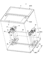
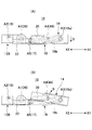
- FIG. 1A is a perspective view of an opening / closing device according to an embodiment of the present invention.
- FIG. 1A shows a closed state of the moving plate
- FIG. 1B shows a opened state of the moving plate.
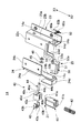
- It is a disassembled perspective view of the switchgear which is one embodiment of the present invention.
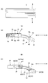
- It is a disassembled perspective view for demonstrating attachment to the electronic device of the switchgear which is one Embodiment of this invention.
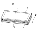
- FIG. 4A is a perspective view showing a closed state of an electronic apparatus equipped with an opening / closing device according to an embodiment of the present invention
- FIG. 4B is a perspective view showing an open state.
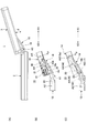
- FIG. 5A is a perspective view showing a state in which the hinge arm, slide arm, and link arm are assembled
- FIG. 5B is an exploded view for explaining the assembly of the hinge arm, slide arm, and link arm.
- FIG. 6A is a perspective view showing a state in which the latch cam is attached to the outer plate
- FIG. 6B is an exploded perspective view for explaining the attachment of the latch cam to the outer plate.
- FIGS. 8A and 8B are schematic configuration diagrams for explaining the operation (part 1) of the switchgear according to the embodiment of the present invention
- FIG. 8A is a side view of the electronic device
- FIG. 8C is a side view of the switchgear with the backlash prevention mechanism removed.
- FIGS. 9A and 9B are schematic configuration diagrams for explaining an operation (part 2) of the switchgear according to the embodiment of the present invention
- FIG. 9A is a side view of the electronic device
- FIG. FIG. 9C is a side view of the switchgear with the backlash prevention mechanism removed.
- It is a schematic block diagram for demonstrating operation
- FIG. 10 (A) is a side view of an electronic device
- FIG.10 (B) is attached with a rattle prevention mechanism.
- FIG. 10C is a side view of the switchgear with the backlash prevention mechanism removed.
- FIG. 11 (A) is a side view of an electronic device
- FIG. 11C is a side view of the switchgear with the backlash prevention mechanism removed.
- FIG. 12 (A) is a side view of an electronic device
- FIG. 12C is a side view of the switchgear with the backlash prevention mechanism removed.
- FIGS. 13A and 13B are views for explaining the operation of the rattling prevention mechanism.
- FIG. 13A is a view showing a state in which the latch is pressed against the circumferential portion of the latch cam
- FIG. It is a figure which shows the state engaged with the cam part.
- 14A and 14B are diagrams for explaining the function of the backlash prevention mechanism.
- FIG. 14A is a view showing a state in which no backlash occurs
- FIG. 14B is a view showing a state in which backlash has occurred.
- FIG. 15A is a plan view of the cover
- FIG. 15B is a side view of the cover
- FIG. 15B is a view for explaining a cover constituting the opening / closing device cover mechanism according to the embodiment of the present invention.
- (C) is a perspective view of the cover
- FIG. 15 (D) is a view for explaining the shape of the cover. It is a perspective view of the cover mechanism for switchgear which is one embodiment of the present invention. It is a figure for demonstrating operation
- FIGS. 1 and 2 are views for explaining an opening / closing device 10 to which an opening / closing device cover mechanism according to an embodiment of the present invention is applied.
- FIGS. 3 and 4 are diagrams illustrating an electronic device provided with the opening / closing device 10.
- FIG. 3 is a diagram for explaining a device 1.
- the electronic device 1 is, for example, a mobile terminal device, and includes a first housing 2, a second housing 3, an opening / closing device 10, and the like.
- a keyboard 5 and the like are provided on the upper surface 2 a of the first housing 2.
- a liquid crystal display device etc. in the upper surface 2a of the 1st housing
- this embodiment demonstrates the example which has arrange
- a liquid crystal display device 4 and the like are provided on the upper surface 3 a of the second housing 3.
- the electronic apparatus 1 is configured to move the second housing 3 between the closed position and the open position with respect to the first housing 2 by providing the opening / closing device 10.
- FIG. 4A shows a state where the second housing 3 is in the closed position (hereinafter referred to as a closed state), and FIG. 4B shows a state where the second housing 3 is in the open position (hereinafter referred to as the open state). It is shown).
- the closed state the second housing 3 is overlaid on the upper portion of the first housing 2, and therefore only the liquid crystal display device 4 is exposed on the surface 3a. Therefore, the liquid crystal display device 4 can be seen from the outside even in the closed state.
- the area of the electronic device 1 in plan view in the closed state is the area in the open state. It is half. Therefore, in the closed state, the electronic device 1 has a small shape and ensures portability.
- a relief opening 7 is formed here, and this relief opening 7 is formed. Is closed by a cover 50.
- the cover 50 and the cover mechanism 25 that drives the cover 50 will be described later for convenience of explanation.
- the second housing 3 is closed by the rotation of the hinge arm 18, the slide arm 20, the link arm 22 and the like (see FIG. 2) constituting the opening / closing device 10.
- the upper surface 2a of the first housing 2 and the upper surface 3a of the second housing 3 are located on the same plane.
- the first casing 2 and the second casing 3 are arranged side by side on the same plane without overlapping.
- the entire upper surfaces 2a and 3a of the respective casings 2 and 3 are exposed upward. Therefore, the entire surface of the upper surface 2a of the first housing 2 can be used as an installation position for the components of the electronic device 1. Similarly, the entire surface of the upper surface 3a of the second housing 3 can be installed for the components of the electronic device 1. Can be used as a position.
- the entire upper surface of the first housing 2 and the entire upper surface of the second housing 3 can be used as the installation positions of the components. Use efficiency of a few spaces can be increased.
- the opening / closing device 10 includes a fixed plate 12, a moving plate 14, a support plate 16, a hinge arm 18, a slide arm 20, a rattle prevention mechanism 21, a link arm 22, And the hinge unit 30 and the cover mechanism 25 according to an embodiment of the present invention.
- the fixing plate 12 and the support plate 16 are fixed to the first housing 2 of the electronic device 1. Specifically, as shown in FIG. 3, the fixing plate 12 and the support plate 16 are fixed to a mounting recess 2 b formed in the first lower half 2 ⁇ / b> B of the first housing 2.
- the first housing 2 is configured by combining the first upper half 2 ⁇ / b> A and the first lower half 2 ⁇ / b> B. Therefore, the first housing 2 is configured integrally with the fixing plate 12 and the support plate 16.
- the fixed plate 12 and the support plate 16 are formed by press-molding a metal plate material.
- the fixing plate 12 has a base portion 12a fixed to the first lower half 2B (see FIG. 3) and standing portions 12b formed on both sides thereof.
- a shaft hole 12c to which the shaft pin 19 is attached is formed in the upright portion 12b on the outer side (Y1 direction side), and a bearing portion 18d of a hinge arm 18 described later is provided on the upright portion 12b on the inner side (Y2 direction side).
- a shaft hole 12d for bearing is formed.
- the support plate 16 has a structure in which a base portion 16a and an upright portion 16b are integrally formed.
- the base portion 16a is a portion that is fixed to the first lower half 2B (see FIG. 3).
- a shaft hole 16c to which a shaft pin 19 described later is attached is formed in the standing portion 16b.
- the moving plate 14 is configured to be movable with respect to the fixed plate 12.
- the moving plate 14 is fixed to the second housing 3 of the electronic device 1. Specifically, as shown in FIG. 3, the moving plate 14 is fixed to a mounting recess 3 b formed in the second lower half 3 ⁇ / b> B of the second housing 3.
- the second housing 3 is configured by combining the second upper half 3A and the second lower half 3B. Therefore, the second housing 3 and the moving plate 14 are integrated.
- the movable plate 14 is arranged separately in the Y1 and Y2 directions. However, it is also possible for each moving plate 14 to be a continuous component.
- the moving plate 14 includes an inner plate 23 and an outer plate 24 formed by press-molding a metal plate material.
- the inner plate 23 has a structure in which a base portion 23 a, an upright portion 23 b, a top plate portion 23 c, and a lid portion 23 d are integrally formed.
- the base part 23a is fixed to the second lower half 3B described above. Further, a shaft hole 14a in which a shaft portion 18a of a hinge arm 18 described later is supported is formed in the standing portion 23b. Further, the top plate portion 23 c is overlapped with the top plate portion 24 c of the outer plate 24 when the inner plate 23 is combined with the outer plate 24 to form the moving plate 14.
- the outer plate 24 has a structure in which a base portion 24a, an upright portion 24b, a top plate portion 24c, and a latch storage portion 24d are integrally formed. .
- the base portion 24a is fixed to the second lower half 3B.
- Shaft holes 14a and 14b are formed in the standing portion 24b.
- a shaft portion 18a of a hinge arm 18 described later is supported.
- the shaft hole 14 b supports a slide arm shaft 44 connected to the slide arm 20.
- the top plate portion 24c is overlapped with the top plate portion 23c of the inner plate 23 when the inner plate 23 is combined with the outer plate 24 to form the moving plate 14 as described above. And by welding both the top-plate parts 23c and 24c in this overlapped state, the inner side plate 23 and the outer side plate 24 become the structure integrated.
- a latch 41 constituting a backlash prevention mechanism 21 described later is stored so as to be slidable in the X1 and X2 directions. Further, in a state where the inner plate 23 and the outer plate 24 are integrated, an arm storage portion 14e (space portion) in which the hinge arm 18 is stored inside as the rotation occurs is formed inside each plate 23, 24.
- the hinge arm 18 is formed at a position between a shaft portion 18a formed at the upper end portion, a shaft hole 18c formed at the lower end portion, and the shaft portion 18a and the shaft hole 18c. And a slide hole 18b (long hole).
- the shaft portion 18a formed at the upper end portion of the hinge arm 18 is rotatably connected to the shaft hole 14a formed in the moving plate 14 as described above.
- a portion where the shaft portion 18a of the hinge arm 18 is rotatably connected to the moving plate 14 is referred to as a third shaft portion A3.
- a base shaft 26 is attached to a shaft hole 18c formed in the lower end portion of the hinge arm 18 located in the arrow Y1 direction in the drawing.
- the hinge arm 18 positioned in the direction of the arrow Y1 in the drawing is formed with a bearing portion 18d, and the shaft hole 18c is formed in the bearing portion 18d.
- the end of the base shaft 26 on the Y1 direction side is inserted into the shaft hole 18c of the bearing portion 18d, and then fixed to the bearing portion 18d by a pin 29. Accordingly, the Y1 direction side hinge arm 18 is configured to rotate integrally with the base shaft 26.
- the shaft hole 18c formed in the lower end portion of the hinge arm 18 located in the direction of the arrow Y2 in the drawing is configured to accommodate a part of the hinge unit 30 therein.
- the head cam 31 and the hinge plate 35 constituting the hinge unit 30 are configured to be accommodated in the shaft hole 18c.
- a hinge shaft 28 constituting the hinge unit 30 is disposed at the end of the base shaft 26 on the Y2 direction side. Specifically, after the base shaft 26 is inserted into the holder portion 28b formed on the hinge shaft 28, the base shaft 26 and the hinge shaft 28 are configured to rotate integrally by being locked by a pin 29. (In the following description, unless otherwise specified, the base shaft 26 includes the hinge shaft 28).
- an oval shaped portion 28a is formed at the tip of the hinge shaft 28 in the Y2 direction.
- the hinge plate 35 disposed in the shaft portion 18a is formed with an oval hole 35a having a shape corresponding to the oval shape portion 28a.
- the oval shape portion 28 a is configured to fit into the oval shape hole 35 a of the hinge plate 35.
- the hinge arm 18 is configured to rotate integrally with the base shaft 26 via the hinge plate 35 and the hinge shaft 28.
- the hinge unit 30 described later has a hinge case 34 fixed to the first lower half 2B (see FIG. 3).
- the base shaft 26 is configured to be supported by the hinge case 34. Therefore, the base shaft 26 is supported on the first housing 2 by the fixing plate 12 and the hinge case 34 that are fixed to the first lower half 2B (first housing 2).
- a portion where the base shaft 26 and the hinge arm 18 are connected is referred to as a first shaft portion A1.
- one end portions of the slide arm 20 and the link arm 22 are connected to the slide hole 18b formed between the shaft portion 18a and the shaft hole 18c of the hinge arm 18.
- the slide hole 18b is formed on the inner side surface of the hinge arm 18 so as to extend in the longitudinal direction.
- the shaft hole 20a formed at the lower end portion of the slide arm 20 and the shaft hole 22a formed at the upper end portion of the link arm 22 are aligned.
- the shaft pin 17 is inserted through the shaft holes 20a and 22a and the slide groove 18b.
- the slider 36 and the spacer 37 are inserted into the end portion of the shaft pin 17 protruding inward from the slide groove 18b.
- the E washer 38 is fixed to the end of the shaft pin 17.
- the slide arm 20 and the link arm 22 are connected to the slide hole 18b.
- the link arm 22 is formed with a boss portion 22c as shown in FIG. 5B, and the boss portion 22c is configured to be slidably engaged with the slide hole 18b. Therefore, the position where the slide arm 20 and the link arm 22 are connected to the slide hole 18b is configured to be movable along the slide hole 18b.
- a portion where the slide arm 20 and the link arm 22 are connected to the slide hole 18b of the hinge arm 18 (that is, the position of the shaft pin 17) is referred to as a fifth shaft portion A5.
- the hinge arm 18 configured as described above moves the movable plate 14 between the closed position and the open position with respect to the fixed plate 12 by rotating around the first shaft portion A1 connected to the fixed plate 12. The function to make it play. Further, when the moving plate 14 moves between the closed position and the open position, the fifth shaft portion A5 slides in the slide hole 18b.
- the lower end of the slide arm 20 is connected to the fifth shaft portion A5. Further, the slide arm shaft 44 is inserted into the shaft hole 20 b formed in the upper end portion of the slide arm 20.
- the slide arm shaft 44 is rotatably supported in a shaft hole 14b formed in the moving plate 14 (see FIG. 6B).
- a portion where the slide arm 20 is rotatably connected to the moving plate 14 is referred to as a fourth shaft portion A4.
- the link arm 22 is configured by combining a link arm main body 22A and a link arm cover 22B.
- the link arm main body 22A is made of metal, and the link arm cover 22B is made of resin.
- the link arm main body 22A is configured to be insert-molded in the link arm cover 22B. With this configuration, the strength of the link arm 22 can be realized by the link arm main body 22A, and the smoothness on the surface of the link arm 22 can be realized by the link arm cover 22B.
- the shaft hole 22a formed at the upper end of the link arm 22 is rotatably connected to the slide hole 18b by the shaft pin 17.
- the shaft hole 22 b formed in the lower end portion of the link arm 22 is connected to the shaft hole 12 c formed in the fixed plate 12 or the shaft hole 16 c formed in the support plate 16 by the shaft pin 19.
- a portion where the lower end portion of the link arm 22 is connected to the fixed plate 12 or the support plate 16 is referred to as a second shaft portion A2. Accordingly, the upper end portion of the link arm 22 is rotatably connected to the fifth shaft portion A5, and the lower end portion is rotatably connected to the second shaft portion A2. Therefore, since the upper end portion of the link arm 22 is also connected to the fifth shaft portion A5, it can be slid along the slide hole 18b.
- the hinge unit 30 includes a hinge shaft 28, a head cam 31, a slide cam 32, hinge springs 33a and 33b, a hinge case 34, a hinge plate 35, and the like.
- the hinge shaft 28 is connected to the base shaft 26 as described above.
- the hinge shaft 28 is inserted in the Y2 direction with respect to the hinge case 34.
- the head cam 31, the slide cam 32, and the like are disposed at a portion protruding inside the hinge case 34 of the hinge shaft 28.
- the head cam 31 and the hinge plate 35 are disposed in the shaft hole 18c of the hinge arm 18 (see FIG. 2). At this time, the hinge arm 18, the base shaft 26, the hinge shaft 28, the head cam 31, and the hinge plate 35 are configured to rotate integrally as described above.
- a protrusion is formed on the outer periphery of the slide cam 32, and a recess that engages with the protrusion is also formed inside the hinge case 34.
- the slide cam 32 is configured such that the rotation of the slide cam 32 is restricted with respect to the hinge case 34 in a state where the slide cam 32 is housed in the hinge case 34.
- the shaft hole formed in the slide cam 32 has a shaft diameter that allows the hinge shaft 28 to rotate. Therefore, the base shaft 26 is configured to be rotatable with respect to the slide cam 32 and to be slidable in the axial direction of the base shaft 26 (arrow Y1, Y2 direction).
- the hinge spring is configured by combining the outer hinge spring 33a and the inner hinge spring 33b.
- the hinge springs 33 a and 33 b have one end abutting against the inner wall of the hinge case 34 and the other end abutting against the slide cam 32. Therefore, the elastic force of the hinge springs 33 a and 33 b acts as a force for pressing the slide cam 32 toward the head cam 31.
- a convex surface and a concave surface that are fitted to each other are formed on the contact surface between the head cam 31 and the slide cam 32, respectively.
- Rotational torque is not generated at the positions where the convex portions of the cams 31 and 32 are in contact with each other (referred to as neutral positions).
- neutral positions positions where the convex portions of the cams 31 and 32 are in contact with each other.
- a rotational torque is generated between the cams 31 and 32 by the elastic force of the hinge spring 33.
- the hinge arm 18 moves between the closed position and the open position, but in this embodiment, the intermediate position between the closed position and the open position is set to be the neutral position of the cams 31 and 32. Yes. Therefore, in a state where the hinge arm 18 is between the closed position and the intermediate position, the hinge arm 18 is urged to rotate toward the closed position by the hinge unit 30, and the hinge arm 18 is between the intermediate position and the open position. In the state, the hinge arm 18 is urged to rotate toward the open position. Therefore, the hinge unit 30 configured as described above constitutes a so-called cam-type semi-auto hinge.
- the moving plate 14 (second housing 3) is opened with respect to the fixed plate 12 (first housing 2), if the opening operation is performed from the closed position to the neutral position, then the moving plate 14 is automatically performed. Moves towards the open position. Conversely, when closing the moving plate 14 with respect to the fixed plate 12, if the closing operation is performed from the open position to the neutral position, then the moving plate 14 automatically moves toward the closing position.
- the semi-auto hinge type hinge unit 30 the operability of the opening / closing device 10 (electronic device 1) can be improved.
- the backlash prevention mechanism 21 includes a slide arm 20, a latch cam 40, a latch 41, and the like as shown in FIGS. 6 and 7 in addition to FIG. As shown in FIG. 14 (A), the play preventing mechanism 21 moves (moves) when the moving plate 14 moves to the open position in the direction indicated by the arrow S in FIG. 14 (B). It has the function of preventing the occurrence of
- the backlash prevention mechanism 21 has a function of preventing backlash generated in the moving plate 14 as described above.
- the latch cam 40 (see FIG. 6) has a generally cylindrical shape, and is a cam having a configuration in which a cam portion 40b is formed in a part of the circumferential portion 40a. Further, the latch cam 40 is formed with a shaft hole 40c and a mounting hole 40d. The latch cam 40 is fixed to the slide arm shaft 44.
- the slide arm shaft 44 is a shaft supported by the shaft hole 14b formed in the moving plate 14 (outer plate 24) as described above. Oval shaped portions 44 a and 44 b are formed at both ends of the slide arm shaft 44.
- the oval shape portion 44 a of the slide arm shaft 44 is connected to the slide arm 20.
- the shaft hole 20b formed in the upper end portion of the slide arm 20 has a shape corresponding to the shape of the oval shape portion 44a. Therefore, the slide arm shaft 44 is configured to rotate integrally with the slide arm 20 by fixing the oval shape portion 44a to the shaft hole 20b.
- a latch plate 43 is attached to the outer side surface of the latch cam 40.
- the latch plate 43 is formed with an oval shape portion 43a and a pair of attachment arms 43b attached to attachment holes 40d formed in the latch cam 40.
- the oval shape portion 43 a is configured to correspond to the shape of the oval shape portion 44 b of the slide arm shaft 44. Therefore, the latch arm 40 is configured to rotate integrally with the slide arm shaft 44 by inserting the slide arm shaft 44 through the attachment hole 40d and fixing the slide arm shaft 44 to the oval shape portion 43a of the latch plate 43 attached to the latch cam 40. . Therefore, the slide arm 20 and the latch cam 40 are configured to rotate integrally.
- the latch 41 shown in FIG. 7 has a prismatic shape, and a protruding portion 41 a is formed at an end facing the latch cam 40.
- the protruding portion 41 a is shaped to engage with a cam portion 40 b formed on the latch cam 40.
- the latch 41 is mounted together with a latch spring 42 in a latch housing portion 24d formed on the outer plate 24.
- a spring receiving portion 41b is formed at the end of the latch 41 on the X1 direction side, and the latch spring 42 is attached to the spring receiving portion 41b.
- the outer plate 24 in which the latch housing portion 24d is formed is welded to the inner plate 23 to constitute the moving plate 14.
- the lid portion 23d formed on the inner plate 23 is configured to cover the upper opening portion of the latch housing portion 24d.
- the upper opening portion of the latch housing portion 24d is closed by the lid portion 23d, so that the latch 41 can be prevented from being detached from the outer plate 24 (moving plate 14).
- the latch cam 40 rotates as the slide arm 20 rotates.
- the latch 41 is configured to always press the protruding portion 41a in the direction (X1 direction) toward the latch cam 40 by the spring force of the latch spring 42.
- FIG. 13A in a state where the protruding portion 41a of the latch 41 is in pressure contact with the circumferential portion 40a of the latch cam 40, the latch cam 40 can rotate, and thus the slide arm 20 can also rotate. It has become.
- the latch 41 restricts the rotation of the latch cam 40 (slide arm 20).
- the fourth shaft portion A4 to which the slide arm 20 is connected is displaced in the S direction.
- the backlash prevention mechanism 21 is configured such that backlash does not occur in the movable plate 14 in the open position by restricting the displacement of the slide arm 20 by the backlash prevention mechanism 21.
- the cover mechanism 25 has a function of closing the relief opening 7 serving as a relief portion of the hinge arm 18 formed in the first housing 2 when the first housing 2 and the second housing 3 are closed. Is.
- the escape opening 7 will be explained first.
- FIG. 12 shows the first housing 2 and the second housing 3 in the open state.
- the upper surface 2a of the first housing 2 and the upper surface 3a of the second housing 3 are on the same surface (a full flat state).
- the shaft portion 18 a of the hinge arm 18 is supported by the moving plate 14 provided in the second housing 3, and the bearing portion 18 d is supported by the fixed plate 12 provided in the first housing 2.
- the hinge arm 18 is configured between the first housing 2 and the second housing 3.
- the hinge arm 18 rotates about the first shaft portion A1
- the moving plate 14 moves relative to the fixed plate 12 and the hinge case 34, and accordingly, the second casing 3 moves to the first casing 2. In contrast, it moves between a closed position and an open position.
- the hinge arm 18 is in a substantially horizontal state. ing.
- the hinge arm 18 is arranged not on the outside of the first housing 2 and the second housing 3 (see Patent Documents 1 to 3) but on the inside.
- the relief openings 7 and 8 are indispensable for the first housing and the second housing to be in a full flat state.
- the relief openings 7 and 8 are opened in the closed state.
- the relief opening 8 formed in the first housing 2 is provided with a bearing portion 18d of the hinge arm 18 in the vicinity thereof in the present embodiment, and the relief opening 8 is formed at the outer peripheral portion of the bearing portion 18d. This will not cause any problems.
- the escape opening 7 formed in the second housing 3 is in an open state as shown in FIG. 18, and problems such as intrusion of dust and a decrease in aesthetics occur.
- the cover mechanism 25 according to the present embodiment is configured to close the escape opening 7 in the closed state.
- the cover mechanism 25 is configured to include a cover 50 and a torsion spring 60 (corresponding to an urging means described in claims).
- the cover 50 is a resin molded product. As shown in FIGS. 15A to 15C, the cover main body 51, the arm portions 52a and 52b, the rotation shafts 53a and 53b, and the guide pins 54 (the pins described in the claims) (Corresponding to the member) is integrally formed.
- the cover body 51 is a part that closes the escape opening 7 in the closed state. Therefore, the shape of the front surface 51a of the cover main body 51 is configured to correspond to the shape of the side surface 3c of the second housing 3 (the side surface shape indicated by the arrow P in FIG. 15D). Therefore, when the escape opening 7 is closed by the cover main body 51, as shown in FIG. 4A, the front surface 51a and the side surface 3c are substantially flush with each other, so that the appearance can be improved.
- the arm part 52 a and the arm part 52 b are formed so as to extend from both sides of the cover main body 51.
- a rotation shaft 53a and a guide pin 54 are formed on one arm portion 52a, and a rotation shaft 53b is formed on the other arm portion 52b.
- the rotary shaft 53a and the rotary shaft 53b are formed on the same axis, and thus the cover 50 is configured to be rotatable around the rotary shafts 53a and 53b.
- the rotating shaft 53a is supported by a shaft hole 14c formed in the inner plate 23 (standing portion 23b) constituting the moving plate 14, and the rotating shaft 53b is supported in a shaft hole 14c formed in the outer plate 24 (standing portion 24b). It is bearing. Therefore, the cover 50 is configured to be rotatably supported between the inner plate 23 and the outer plate 24.
- the arm storage portion 14e into which the hinge arm 18 enters and is stored is formed inside the inner plate 23 and the outer plate 24. Therefore, the cover 50 is disposed in the arm storage portion 14e.
- the distance between the pair of arm portions 52a and 52b is larger than the width dimension of the hinge arm 18 (indicated by the arrow W1 in FIG. 5B). It is set large (W2> W1). Therefore, when the hinge arm 18 enters the arm storage portion 14e, the hinge arm 18 can enter between the pair of arm portions 52a and 52b of the cover 50.
- the guide pin 54 is formed at a position deviated from the rotation shaft 53a. Also, a crescent-shaped guide groove 14d is formed in the vicinity of the position where 14c of the standing portion 23b is formed.
- the guide pin 54 is configured to be movable in the guide groove 14d. That is, when the cover 50 rotates around the rotation shafts 53a and 53b in the direction of the arrows E1 and E2 in the movement plate 14 (arm storage portion 14e), the guide pin 54 also rotates within the guide groove 14d. Is rotated in the E1 and E2 directions.
- the torsion spring 60 is configured such that a winding portion 60c located at the center is supported by a rotating shaft 53a, one end portion 60a is connected to the guide pin 54, and the other end portion 60b abuts on the base portion 23a. .
- the torsion spring 60 is configured to elastically bias the guide pin 54 in the direction of arrow E2.
- the cover 50 is urged to rotate by the torsion spring 60 in the E2 direction (counterclockwise in FIGS. 16 and 17) about the rotation shafts 53a and 53b.
- the guide pin 54 abuts against the end of the guide groove 14d on the E2 direction side, further rotation is restricted.
- the front surface 51a of the cover 50 passes through the relief opening 7 of the second housing 3 in a state where the guide pin 54 is in contact with the end of the guide groove 14d on the E2 direction side and the moving plate 14 is moved to the closed position. It has been moved to the closing position (hereinafter, the position where the cover 50 closes the escape opening 7 is referred to as the closing position). Further, when the cover 50 is in this closed position, the hinge arm 18 is in a state of being separated from the cover 50.
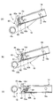
- FIG. 16 shows a state in which the hinge arm 18 is separated from the cover 50.
- the cover 50 is rotated in the E2 direction by the elastic force of the torsion spring 60, and thus the cover 50 is located at the closed position.
- the hinge arm 18 engages with the cover main body 51 of the cover 50 as the hinge arm 18 advances into 14. Accordingly, the cover 50 is urged by the hinge arm 18 that relatively proceeds in the G direction, and rotates in the direction of the arrow E1 from the closed position about the rotation shafts 53a and 53b against the elastic force of the torsion spring 60. .
- the guide pin 54 also moves in the guide groove 14d in the E1 direction.
- the elastic force of the torsion spring 60 is also set to a relatively small elastic force that can move and urge the cover 50 to the closed position. Therefore, even if the cover 50 is provided in the arm storage portion 14e, the cover 50 does not interfere with the movement of the hinge arm 18 when it moves into the arm storage portion 14e.
- FIG. 1B shows a state where the hinge arm 18 is housed in the arm housing portion 14e.
- the cover body 51 is positioned above the hinge arm 18 by the rotation of the cover 50. Further, in this state, the hinge arm 18 is in a state of entering between the pair of arm portions 52 a and 52 b of the cover 50.
- FIG 8 to 12 show an operation in which the second housing 3 and the moving plate 14 move from the closed state to the open state.
- (A) shows the operation of the electronic device 1
- (B) shows the operation of the switchgear 10 provided with the backlash prevention mechanism 21
- (C) shows the state where the backlash prevention mechanism 21 is removed. The operation of the switchgear 10 is shown.
- FIG. 8 shows the electronic device 1 and the opening / closing device 10 in the closed state.
- the second housing 3 of the electronic device 1 is in a state of overlapping the upper portion of the first housing 2.
- the hinge arm 18 of the opening / closing device 10 is rotated counterclockwise in the figure about the first shaft portion A1 when viewed from the upright position. It has become.
- the fifth shaft portion A5 is located at the end portion on the third shaft portion A3 side (end portion close to the moving plate 14) in the slide hole 18b. Further, the hinge arm 18, the slide arm 20, and the link arm 22 are arranged in a substantially straight line, and thus are compact.
- the hinge unit 30 urges the hinge arm 18 counterclockwise in the drawing with the first shaft portion A1 as the center. Further, the backlash prevention mechanism 21 is in a state where the latch 41 is in pressure contact with the cam portion 40b of the latch cam 40 as shown in FIG. For this reason, the slide arm 20 is in a rotatable state.
- the cover mechanism 25 moves in the arrow E2 direction when the cover 50 is separated from the hinge arm 18 in the closed position.
- the movable plate 14 is in a position moved in the X2 direction with respect to the base shaft 26, and in this state, the cover 50 (cover body 51) is a closed position where the escape opening 7 is blocked. Is located. Therefore, in the closed state, the escape opening 7 is closed by the cover 50 as described above, so that dust can be prevented from entering and the appearance can be improved.
- the lower end portion of the slide arm 20 and the upper end portion of the link arm 22 are connected to a fifth shaft portion A5 movably engaged with the hinge arm 18. Therefore, when the hinge arm 18 rotates in the P direction, the slide arm 20 and the link arm 22 move the fifth shaft portion A5 in the direction toward the first shaft portion A1 along the slide hole 18b (indicated by an arrow Z in the figure). Direction). As described above, since the fifth shaft portion A5 moves along the slide hole 18b, the arms 18, 20, and 22 can smoothly rotate.
- the moving plate 14 is supported by the slide arm 20 with respect to the hinge arm 18, and the hinge arm 18 is supported by the link arm 22 with respect to the fixed plate 12 and the hinge case 34. For this reason, the moving posture of the moving plate 14 is stable, and the moving plate 14 is not unnecessarily displaced with respect to the hinge arm 18.
- FIG. 10 shows a state where the second casing 3 (moving plate 14) has moved to the neutral position.
- the position where the hinge arm 18 stands upright from the closed state is set to be the neutral position.
- the apex portions of the convex surfaces of the head cam 31 and the slide cam 32 of the hinge unit 30 are in contact with each other.
- the rotational biasing force of the hinge arm 18 by the hinge unit 30 is instantaneously lost.
- the second housing 3 moving plate 14
- the rotational torque generated on the contact surface of the head cam 31 and the slide cam 32 is reversed, and the moving plate 14 is moved.
- the base shaft 26 is urged to rotate in the direction of movement toward the open position.
- the hinge arm 18 is urged to rotate clockwise (opening direction) about the first shaft portion A1. Therefore, after the second casing 3 (moving plate 14) is slightly operated from the neutral position toward the open position, the second casing 3 (moving plate 14) is automatically moved as shown in FIGS. Move sequentially toward the open position.
- FIG. 11 shows a state in which the hinge arm 18 is further rotated from the neutral position to the vicinity of the open position.
- the hinge arm 18 acts to push the third shaft portion A3 downward.
- the angle (tilt angle ⁇ ) of the second housing 3 (moving plate 14) with respect to the horizontal direction gradually decreases. In other words, the posture of the second housing 3 (moving plate 14) approaches the above-mentioned horizontal state.
- the rattle prevention mechanism 21 is configured such that the protruding portion 41a of the latch 41 engages with the cam portion 40b of the latch cam 40 in a state where the moving plate 14 has moved to the closed position. Therefore, the rotation of the slide arm 20 is restricted by the backlash prevention mechanism 21 in a state where the moving plate 14 has moved to the closed position. Thereby, as described with reference to FIG. 14, it is possible to prevent the play caused by the displacement of the fourth shaft portion A4 of the moving plate 14 in the direction indicated by the arrow S. Therefore, the second housing 3 can be prevented from rattling in the open state, and the usability of the electronic device 1 can be improved.
- the state shown in FIG. 17 (A) is equivalent to the state shown in FIG. In the state shown in FIG. 17A, the hinge arm 18 is separated from the cover 50, and the cover 50 is moved in the direction of arrow E2 by the elastic force of the torsion spring 60.
- FIG. 17C shows the cover mechanism 25 in the open state, which is equivalent to the state shown in FIG. In the closed state, the hinge arm 18 is housed in the arm housing portion 14e as described above, and the cover main body 51 is positioned above the hinge arm 18 as the cover 50 rotates.
- the cover 50 when the second housing 3 (moving plate 14) is in the closed state, the cover 50 (cover body 51) closes the escape opening 7, so 2 It is possible to prevent intrusion into the housing 3 and improve aesthetics. Further, in the open state, the cover 50 moves by being urged by the hinge arm 18, so that it does not interfere with the storage of the hinge arm 18 in the arm storage portion 14e.
Landscapes
- Engineering & Computer Science (AREA)
- Theoretical Computer Science (AREA)
- Computer Hardware Design (AREA)
- Physics & Mathematics (AREA)
- Human Computer Interaction (AREA)
- General Engineering & Computer Science (AREA)
- General Physics & Mathematics (AREA)
- Signal Processing (AREA)
- Mathematical Physics (AREA)
- Telephone Set Structure (AREA)
- Casings For Electric Apparatus (AREA)
- Specific Sealing Or Ventilating Devices For Doors And Windows (AREA)
Abstract
La présente invention se rapporte à un mécanisme de couvercle pour un dispositif qui s'ouvre et qui se ferme. Le mécanisme selon l'invention est mis en œuvre dans un dispositif qui s'ouvre et qui se ferme, le dispositif comprenant : une plaque fixe, qui est rattachée à un premier corps de boîtier ; une plaque mobile, qui est rattachée à un second corps de boîtier et qui est apte à se déplacer par rapport à la plaque fixe ; un bras articulé, qui est placé entre la plaque fixe et la plaque mobile et qui, en tournant, déplace la plaque mobile entre une position fermée dans laquelle le premier corps de boîtier et le second corps de boîtier sont superposés et une position ouverte dans laquelle la surface du premier corps de boîtier et la surface du second corps de boîtier sont sensiblement coplanaires ; et une section d'échappement, qui est formée dans le second corps de boîtier de telle sorte que le bras articulé et le second corps de boîtier n'interfèrent pas l'un avec l'autre dans la position ouverte. Le mécanisme de couvercle selon l'invention ouvre et ferme la section d'échappement. Le mécanisme de couvercle possède un couvercle : qui est prévu sur la plaque mobile ; qui ferme la section d'échappement quand la plaque mobile est placée dans la position fermée ; et qui, sous l'effet de la mise en prise avec le bras articulé rotatif et de son entraînement en mouvement, se déplace à partir de la position de fermeture de la section d'échappement. Le mécanisme de couvercle selon l'invention est pourvu de moyens d'entraînement adaptés pour entraîner le couvercle dans la direction de fermeture de la section d'échappement.
Priority Applications (3)
| Application Number | Priority Date | Filing Date | Title |
|---|---|---|---|
| EP11826805.1A EP2621149B1 (fr) | 2010-09-22 | 2011-09-16 | Dispositif d'ouverture/fermeture |
| US13/822,348 US9094490B2 (en) | 2010-09-22 | 2011-09-16 | Cover mechanism for opening and closing device |
| CN201180044784.2A CN103119919B (zh) | 2010-09-22 | 2011-09-16 | 开闭装置用盖结构 |
Applications Claiming Priority (2)
| Application Number | Priority Date | Filing Date | Title |
|---|---|---|---|
| JP2010211522A JP5611743B2 (ja) | 2010-09-22 | 2010-09-22 | 開閉装置用カバー機構 |
| JP2010-211522 | 2010-09-22 |
Publications (1)
| Publication Number | Publication Date |
|---|---|
| WO2012039360A1 true WO2012039360A1 (fr) | 2012-03-29 |
Family
ID=45873847
Family Applications (1)
| Application Number | Title | Priority Date | Filing Date |
|---|---|---|---|
| PCT/JP2011/071246 WO2012039360A1 (fr) | 2010-09-22 | 2011-09-16 | Mécanisme de couvercle pour dispositif qui s'ouvre et qui se ferme |
Country Status (5)
| Country | Link |
|---|---|
| US (1) | US9094490B2 (fr) |
| EP (1) | EP2621149B1 (fr) |
| JP (1) | JP5611743B2 (fr) |
| CN (1) | CN103119919B (fr) |
| WO (1) | WO2012039360A1 (fr) |
Families Citing this family (11)
| Publication number | Priority date | Publication date | Assignee | Title |
|---|---|---|---|---|
| JP5599226B2 (ja) * | 2010-05-17 | 2014-10-01 | 三菱製鋼株式会社 | 開閉装置 |
| JP5161336B2 (ja) * | 2010-09-10 | 2013-03-13 | 三菱製鋼株式会社 | 開閉装置 |
| KR101285799B1 (ko) * | 2012-02-03 | 2013-07-23 | 권성태 | 이동 단말기용 힌지장치 |
| JP6261784B1 (ja) * | 2017-01-18 | 2018-01-17 | レノボ・シンガポール・プライベート・リミテッド | 電子機器 |
| TWI668556B (zh) * | 2017-02-08 | 2019-08-11 | 仁寶電腦工業股份有限公司 | 電子裝置及其鉸鏈組件 |
| KR102426694B1 (ko) | 2017-05-02 | 2022-07-29 | 삼성전자주식회사 | 플렉서블 디스플레이를 포함하는 전자 장치 |
| TWI688323B (zh) * | 2017-11-22 | 2020-03-11 | 仁寶電腦工業股份有限公司 | 雙軸樞紐器以及電子裝置 |
| WO2019172883A1 (fr) * | 2018-03-06 | 2019-09-12 | Hewlett-Packard Development Company, L.P. | Ensembles charnière ayant des arbres de col composites |
| USD891426S1 (en) * | 2018-05-11 | 2020-07-28 | Fuvi Cognitive Network Corp. | Mobile device for visual and cognitive communication assistance |
| US11447992B2 (en) * | 2021-01-20 | 2022-09-20 | Leohab Enterprise Co., Ltd. | Pivot device with an interlocking lifting mechanism |
| KR20220109016A (ko) * | 2021-01-28 | 2022-08-04 | 삼성전자주식회사 | 암부와 회전부의 개선된 결합 구조를 가지는 힌지 구조 및 이를 포함하는 전자 장치 |
Citations (7)
| Publication number | Priority date | Publication date | Assignee | Title |
|---|---|---|---|---|
| JPH0479296A (ja) * | 1990-07-20 | 1992-03-12 | Sharp Corp | 二つ折り電子機器の配線カバー機構 |
| JP2009059102A (ja) | 2007-08-30 | 2009-03-19 | Sony Ericsson Mobilecommunications Japan Inc | 携帯情報端末 |
| JP2009071588A (ja) | 2007-09-13 | 2009-04-02 | Kyocera Corp | 携帯通信端末機 |
| JP2009218674A (ja) | 2008-03-07 | 2009-09-24 | Nec Corp | 携帯端末装置 |
| JP2010065840A (ja) * | 2008-09-15 | 2010-03-25 | Fujitsu Ltd | 携帯機器 |
| JP2010211522A (ja) | 2009-03-10 | 2010-09-24 | Ricoh Co Ltd | 画像形成装置、情報処理装置、情報処理方法、及びプログラム |
| JP2011114522A (ja) * | 2009-11-26 | 2011-06-09 | Kyocera Corp | 携帯型電子機器 |
Family Cites Families (15)
| Publication number | Priority date | Publication date | Assignee | Title |
|---|---|---|---|---|
| DE9307328U1 (fr) | 1993-05-14 | 1993-07-08 | Wilhelm Altendorf Gmbh & Co Kg, 4950 Minden, De | |
| US5384844A (en) * | 1993-07-30 | 1995-01-24 | Ericsson Ge Mobile Communications, Inc. | Pivotable housing for hand-held transceiver |
| KR0138235B1 (ko) * | 1994-08-23 | 1998-07-01 | 김광호 | 휴대용 무선전화기의 힌지장치 |
| US6148079A (en) * | 1998-03-19 | 2000-11-14 | Qualcomm Incorporated | Hinge apparatus for flip style portable phone |
| US6088240A (en) * | 1998-06-15 | 2000-07-11 | Motorola, Inc. | Hinged flip assembly for a communication device |
| KR200241123Y1 (ko) * | 2001-04-25 | 2001-10-12 | 원종림 | 이동통신단말기의 커버 개폐장치 |
| JP2003120653A (ja) * | 2001-10-17 | 2003-04-23 | Ohashi Technica Inc | ヒンジ装置及びそれを用いた携帯電話機 |
| US7366555B2 (en) * | 2002-09-30 | 2008-04-29 | Nokia Corporation | Mobile station enclosure |
| US7155266B2 (en) * | 2004-04-21 | 2006-12-26 | Nokia Corporation | Hinge for fold phone |
| US7627337B2 (en) | 2006-04-17 | 2009-12-01 | Nokia Corporation | Dual lever slide mechanism for extendible device housings |
| EP2100432A1 (fr) * | 2006-12-28 | 2009-09-16 | Nokia Corporation | Appareil à charnière pour dispositif électronique rabattable |
| US8060157B2 (en) * | 2007-11-27 | 2011-11-15 | Nokia Corporation | Recessed hinge |
| KR101211549B1 (ko) * | 2008-03-05 | 2012-12-12 | 교세라 가부시키가이샤 | 개폐식 소형 전자기기 |
| JP5324171B2 (ja) * | 2008-09-22 | 2013-10-23 | 日本電気株式会社 | スライド式小型電子機器 |
| CN201374452Y (zh) * | 2009-02-24 | 2009-12-30 | 佛山市顺德区顺达电脑厂有限公司 | 卡式插槽防尘盖 |
-
2010
- 2010-09-22 JP JP2010211522A patent/JP5611743B2/ja active Active
-
2011
- 2011-09-16 CN CN201180044784.2A patent/CN103119919B/zh active Active
- 2011-09-16 EP EP11826805.1A patent/EP2621149B1/fr active Active
- 2011-09-16 WO PCT/JP2011/071246 patent/WO2012039360A1/fr active Application Filing
- 2011-09-16 US US13/822,348 patent/US9094490B2/en active Active
Patent Citations (7)
| Publication number | Priority date | Publication date | Assignee | Title |
|---|---|---|---|---|
| JPH0479296A (ja) * | 1990-07-20 | 1992-03-12 | Sharp Corp | 二つ折り電子機器の配線カバー機構 |
| JP2009059102A (ja) | 2007-08-30 | 2009-03-19 | Sony Ericsson Mobilecommunications Japan Inc | 携帯情報端末 |
| JP2009071588A (ja) | 2007-09-13 | 2009-04-02 | Kyocera Corp | 携帯通信端末機 |
| JP2009218674A (ja) | 2008-03-07 | 2009-09-24 | Nec Corp | 携帯端末装置 |
| JP2010065840A (ja) * | 2008-09-15 | 2010-03-25 | Fujitsu Ltd | 携帯機器 |
| JP2010211522A (ja) | 2009-03-10 | 2010-09-24 | Ricoh Co Ltd | 画像形成装置、情報処理装置、情報処理方法、及びプログラム |
| JP2011114522A (ja) * | 2009-11-26 | 2011-06-09 | Kyocera Corp | 携帯型電子機器 |
Also Published As
| Publication number | Publication date |
|---|---|
| CN103119919A (zh) | 2013-05-22 |
| US20130192140A1 (en) | 2013-08-01 |
| JP5611743B2 (ja) | 2014-10-22 |
| US9094490B2 (en) | 2015-07-28 |
| EP2621149A4 (fr) | 2017-04-12 |
| EP2621149B1 (fr) | 2018-03-28 |
| CN103119919B (zh) | 2015-12-02 |
| EP2621149A1 (fr) | 2013-07-31 |
| JP2012067470A (ja) | 2012-04-05 |
Similar Documents
| Publication | Publication Date | Title |
|---|---|---|
| JP5611743B2 (ja) | 開閉装置用カバー機構 | |
| JP5161336B2 (ja) | 開閉装置 | |
| JP5599226B2 (ja) | 開閉装置 | |
| JP4357900B2 (ja) | 小型情報端末用スライドヒンジ | |
| JP4638764B2 (ja) | ヒンジ機構及び携帯端末 | |
| JP4693069B2 (ja) | 摺動・回転取付ユニット及びそれを用いた携帯電話機 | |
| JP4546888B2 (ja) | ヒンジ装置並びにヒンジ装置を用いた電子機器 | |
| JP4537930B2 (ja) | 携帯機器の水平回転機構 | |
| JP2008092264A (ja) | ヒンジ機構および携帯端末 | |
| JP4111392B2 (ja) | 携帯端末装置 | |
| JP4619343B2 (ja) | 折り畳み式携帯端末機 | |
| JP4899190B2 (ja) | 携帯電子機器 | |
| US20080092336A1 (en) | Hinge mechanism and portable terminal | |
| JP2009041729A (ja) | ヒンジ機構および携帯端末 | |
| JP2006177481A (ja) | ヒンジ装置及びヒンジ装置を用いた携帯電話機 | |
| JP4899191B2 (ja) | 携帯電子機器 | |
| JP2006283836A (ja) | 連結機構及び携帯端末 | |
| JP2009047258A (ja) | ヒンジ機構および携帯端末 | |
| WO2010064339A1 (fr) | Dispositif électronique portable pliable | |
| JP4313286B2 (ja) | ヒンジ装置を用いた携帯電話機 | |
| JP5218358B2 (ja) | 携帯機器 | |
| JP4681058B2 (ja) | ヒンジ装置 | |
| JP2009138785A (ja) | ヒンジ装置および携帯端末 |
Legal Events
| Date | Code | Title | Description |
|---|---|---|---|
| WWE | Wipo information: entry into national phase |
Ref document number: 201180044784.2 Country of ref document: CN |
|
| 121 | Ep: the epo has been informed by wipo that ep was designated in this application |
Ref document number: 11826805 Country of ref document: EP Kind code of ref document: A1 |
|
| WWE | Wipo information: entry into national phase |
Ref document number: 13822348 Country of ref document: US |
|
| WWE | Wipo information: entry into national phase |
Ref document number: 2011826805 Country of ref document: EP |
|
| NENP | Non-entry into the national phase |
Ref country code: DE |