WO2012033067A1 - 光ピックアップ装置 - Google Patents
光ピックアップ装置 Download PDFInfo
- Publication number
- WO2012033067A1 WO2012033067A1 PCT/JP2011/070201 JP2011070201W WO2012033067A1 WO 2012033067 A1 WO2012033067 A1 WO 2012033067A1 JP 2011070201 W JP2011070201 W JP 2011070201W WO 2012033067 A1 WO2012033067 A1 WO 2012033067A1
- Authority
- WO
- WIPO (PCT)
- Prior art keywords
- laser light
- light
- wavelength
- polarized light
- laser
- Prior art date
- Legal status (The legal status is an assumption and is not a legal conclusion. Google has not performed a legal analysis and makes no representation as to the accuracy of the status listed.)
- Ceased
Links
Images
Classifications
-
- G—PHYSICS
- G11—INFORMATION STORAGE
- G11B—INFORMATION STORAGE BASED ON RELATIVE MOVEMENT BETWEEN RECORD CARRIER AND TRANSDUCER
- G11B7/00—Recording or reproducing by optical means, e.g. recording using a thermal beam of optical radiation by modifying optical properties or the physical structure, reproducing using an optical beam at lower power by sensing optical properties; Record carriers therefor
- G11B7/12—Heads, e.g. forming of the optical beam spot or modulation of the optical beam
- G11B7/135—Means for guiding the beam from the source to the record carrier or from the record carrier to the detector
- G11B7/1395—Beam splitters or combiners
-
- G—PHYSICS
- G11—INFORMATION STORAGE
- G11B—INFORMATION STORAGE BASED ON RELATIVE MOVEMENT BETWEEN RECORD CARRIER AND TRANSDUCER
- G11B7/00—Recording or reproducing by optical means, e.g. recording using a thermal beam of optical radiation by modifying optical properties or the physical structure, reproducing using an optical beam at lower power by sensing optical properties; Record carriers therefor
- G11B7/12—Heads, e.g. forming of the optical beam spot or modulation of the optical beam
- G11B7/135—Means for guiding the beam from the source to the record carrier or from the record carrier to the detector
- G11B7/1365—Separate or integrated refractive elements, e.g. wave plates
-
- G—PHYSICS
- G11—INFORMATION STORAGE
- G11B—INFORMATION STORAGE BASED ON RELATIVE MOVEMENT BETWEEN RECORD CARRIER AND TRANSDUCER
- G11B7/00—Recording or reproducing by optical means, e.g. recording using a thermal beam of optical radiation by modifying optical properties or the physical structure, reproducing using an optical beam at lower power by sensing optical properties; Record carriers therefor
- G11B2007/0003—Recording, reproducing or erasing systems characterised by the structure or type of the carrier
- G11B2007/0006—Recording, reproducing or erasing systems characterised by the structure or type of the carrier adapted for scanning different types of carrier, e.g. CD & DVD
-
- G—PHYSICS
- G11—INFORMATION STORAGE
- G11B—INFORMATION STORAGE BASED ON RELATIVE MOVEMENT BETWEEN RECORD CARRIER AND TRANSDUCER
- G11B7/00—Recording or reproducing by optical means, e.g. recording using a thermal beam of optical radiation by modifying optical properties or the physical structure, reproducing using an optical beam at lower power by sensing optical properties; Record carriers therefor
- G11B7/12—Heads, e.g. forming of the optical beam spot or modulation of the optical beam
- G11B7/125—Optical beam sources therefor, e.g. laser control circuitry specially adapted for optical storage devices; Modulators, e.g. means for controlling the size or intensity of optical spots or optical traces
- G11B7/127—Lasers; Multiple laser arrays
- G11B7/1275—Two or more lasers having different wavelengths
Definitions
- the present invention relates to an optical pickup device.
- optical pickup devices that read and write signals to and from an optical disc (optical recording medium) are compatible with a plurality of optical discs having different standards.
- Patent Document 1 corresponds to the DVD (registered trademark) (Digital Versatile Disc) standard using a red laser beam having a wavelength of 650 nm and the CD (Compact Disc) (trademark) standard using an infrared laser beam having a wavelength of 780 nm
- An optical pickup device optical head device
- a DVD light source and a CD standard optical disk can be used by using a two-wavelength multi-laser light source in which a laser light source having a wavelength of 650 nm and a laser light source having a wavelength of 780 nm are provided in the same package.
- An optical pickup device is disclosed.
- the cost of the optical pickup device can be reduced, the size can be reduced, and the manufacturing can be facilitated.
- FIG. 5 shows an example of the configuration of an optical pickup device corresponding to the DVD standard and the CD standard and using a common photodetector and laser light source.
- Laser light emitted from the laser light source unit 1 enters the polarization beam splitter 3 through the diffraction grating 2 as, for example, S-polarized light.
- the S-polarized light is reflected by the polarization beam splitter 3 and the mirror 4, enters the quarter-wave plate 6 through the collimator lens 5, and is converted into circularly polarized light C ⁇ b> 1 (for example, right circularly polarized light).
- the light is condensed on the optical disk 9 by the objective lens 7.
- the laser light reflected by the optical disk 9 enters the quarter-wave plate 6 through the objective lens 7 as circularly polarized light C2 (for example, left circularly polarized light) in the direction opposite to C1.
- the circularly polarized light C2 is converted into P-polarized light orthogonal to S-polarized light by the quarter wavelength plate 6, reflected by the mirror 4, transmitted through the polarization beam splitter 3, and incident on the photodetector 8. .
- a broadband quarter wavelength plate capable of converting linearly polarized light into circularly polarized light with respect to laser light with wavelengths ⁇ 1 to ⁇ 2.
- a narrow-band quarter-wave plate it is desirable to use a quarter-wave plate corresponding to the wavelength ⁇ 1 of the DVD standard having a higher recording density.
- the narrow-band quarter-wave plate can convert S-polarized light into circularly-polarized light C1 for laser light in the vicinity of the wavelength ⁇ 1, as with the wide-band quarter-wave plate 6.
- the S-polarized light is converted into elliptically polarized light E1 (for example, right elliptically polarized light) for the laser light having the wavelength ⁇ 2.
- the laser beam reflected by the optical disk 9 enters the narrow-band quarter-wave plate 16 through the objective lens 7 as elliptically polarized light E2 (for example, left elliptically polarized light) in the direction opposite to E1.
- the elliptically polarized light E2 is converted into P-polarized light by the quarter-wave plate 16.
- the quarter-wave plate 16 causes the influence of the birefringence as shown in FIG.
- Some S-polarized light components may remain in the converted P-polarized light.
- a small amount of elliptically polarized light (denoted as “P + s” in FIG. 7) in which a slight S-polarized component remains in the P-polarized light is incident on the polarization beam splitter 3.
- the light is reflected by the splitter 3 and returned to the laser light source unit 1. For this reason, the reading and writing performance of the optical pickup device deteriorates due to the influence of the return light to the laser light source unit 1.
- the main present invention that solves the above-described problems includes first and second laser light sources that emit laser beams of first and second wavelengths, respectively, and selectively selects the laser light of the first or second wavelength.
- a laser light source unit that emits light
- an objective lens that focuses the laser light emitted from the laser light source unit on an optical recording medium
- a photodetector that detects the laser light reflected by the optical recording medium
- the laser light emitted from the laser light source part and the laser light reflected by the optical recording medium are separated according to the wavelength and the polarization direction, and the laser light emitted from the laser light source part is guided to the objective lens.
- a light separating section for guiding the laser light reflected by the optical recording medium to the light detector, the first light beam disposed between the light separating section and the objective lens, and incident through the light separating section.
- Wavelength A quarter-wave plate for converting light from linearly polarized light to circularly polarized light, and converting the laser light having the second wavelength incident via the light separating unit from linearly polarized light to elliptically polarized light, and
- the second wavelength laser beam emitted from the laser light source unit enters the light separating unit as first linearly polarized light, and the light separating unit enters the first wavelength plate through the quarter wavelength plate.
- the phase is shifted so as to reduce the component of the first linearly polarized light with respect to the laser light having the second wavelength.
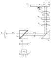
- 1st Embodiment of this invention it is a schematic diagram which shows an example of the intensity
- 1st Embodiment of this invention it is a schematic diagram which shows an example of the intensity
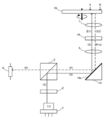
- 2nd Embodiment of this invention It is a figure explaining operation
- the optical pickup device shown in FIG. 1 includes a laser light source unit 1, a diffraction grating 2, a polarizing beam splitter 13 (polarizing member), a mirror 4, a collimator lens 5, a quarter wavelength plate 16, an objective lens 7, and light.
- a detector 8 is included. Further, the optical pickup device can read and write signals to and from a plurality of optical discs having different standards such as the DVD standard and the CD standard. In FIG. The case where it is set as a target is shown.
- the polarization beam splitter 13 and the mirror 4 correspond to a light separation unit.
- the quarter wavelength plate 16 a narrow band quarter wavelength plate corresponding to the wavelength ⁇ 1 (first wavelength) of the DVD standard is used. For this reason, the quarter-wave plate 16 converts linearly polarized light into circularly polarized light for laser light in the vicinity of the wavelength ⁇ 1, while for laser light having a wavelength ⁇ 2 (second wavelength) for CD standards. , Convert linearly polarized light into elliptically polarized light.
- the laser light source unit 1 includes (first and second) laser light sources that emit laser beams with wavelengths ⁇ 1 and ⁇ 2, respectively, and selectively emits laser light with a wavelength ⁇ 1 or ⁇ 2 depending on the set optical disc. Is configured to do.
- a two-wavelength multi-laser light source in which a laser light source having a wavelength ⁇ 1 and a laser light source having a wavelength ⁇ 2 are provided in the same package is used as the laser light source unit 1.
- the laser light source unit 1 is configured by a separate laser light source that emits laser light of each wavelength, and a diffraction grating and a polarization beam splitter are provided corresponding to each laser light. Also good. In this case, FIG.
- FIG. 1 shows the diffraction grating 2 and the polarization beam splitter 13 corresponding to the laser light having the wavelength ⁇ 2, and the diffraction grating and the polarization beam splitter corresponding to the laser light having the wavelength ⁇ 1 are not shown. .
- a solid line arrow indicates an optical path (outward path) until the laser light emitted from the laser light source unit 1 is collected on the optical disk 19, and a broken line arrow indicates the laser light reflected by the optical disk 19. Indicates the optical path (return path) until the light enters the photodetector 8.
- the diffraction grating 2 and the polarization beam splitter 13 are arranged so that the laser light emitted from the laser light source unit 1 enters the polarization beam splitter 13 via the diffraction grating 2. Further, the polarizing beam splitter 13 and the mirror 4 are arranged so that the laser light reflected by the polarizing beam splitter 13 is incident on the mirror 4.
- the mirror 4, the collimator lens 5, the quarter wavelength plate 16, and the objective lens 7 are optical disks in which the laser light reflected by the mirror 4 passes through the collimator lens 5, the quarter wavelength plate 16, and the objective lens 7. 19 is arranged so as to be condensed.
- the laser beam reflected by the optical disk 19 is incident on the mirror 4 again via the objective lens 7, the quarter-wave plate 16, and the collimator lens 5.
- the mirror 4, the polarization beam splitter 13, and the photodetector 8 are configured such that the laser beam reflected by the mirror 4 is incident on the polarization beam splitter 13 and the laser beam transmitted through the polarization beam splitter 13 is further detected by the photodetector 8. It is arrange
- the laser light source unit 1 selects and emits laser light having a wavelength ⁇ 2.
- the laser light emitted from the laser light source unit 1 is divided into a main beam (0th order diffracted light) and a sub beam (for example, ⁇ 1st order diffracted light) by the diffraction grating 2 and then, for example, S-polarized light (first linearly polarized light). ) Enters the polarization beam splitter 13.
- the polarization beam splitter 13 reflects most of the S-polarized component (for example, about 90 to 100%) included in the laser light having the wavelength ⁇ 2, and also partially (for example, 20 to 30) of the P-polarized (second linearly polarized) component. %). Therefore, the polarization beam splitter 13 reflects most of the laser light incident through the diffraction grating 2, and the reflected laser light is incident on the mirror 4 and further reflected.
- the laser light reflected by the mirror 4 is converted into parallel light by the collimator lens 5 and then enters the quarter-wave plate 16.
- the quarter wavelength plate 16 converts the laser light incident through the collimator lens 5 from S-polarized light to elliptically polarized light E1 (for example, right elliptically polarized light), and the objective lens 7 converts the elliptically polarized light E1 onto the optical disk 19. Condensed to
- the laser beam reflected by the optical disk 19 enters the quarter-wave plate 16 through the objective lens 7 as elliptically polarized light E2 (for example, left elliptically polarized light) in the direction opposite to E1.
- the quarter-wave plate 16 converts the incident laser light from elliptically polarized light E2 to P-polarized light.
- some S-polarized light components remain in the P-polarized light, resulting in some elliptically polarized light P + s.
- the slightly elliptically polarized light P + s enters the mirror 4 via the collimator lens 5 and is further reflected.
- the laser beam reflected by the mirror 4 enters the polarization beam splitter 13. Further, since the polarization beam splitter 13 includes, for example, a special polarizing film 13a, a part of the P-polarized component is transmitted and the phase of the S-polarized component is substantially reduced with respect to the incident laser light having the wavelength ⁇ 2. Shift by 90 ° (about 90 ° ⁇ 15 °, preferably about 90 ° ⁇ 5 °). A special film such as the polarizing film 13a is formed on a desired surface of the polarizing beam splitter 13 based on, for example, a vacuum deposition method or a sputtering method.
- the polarizing film 13a is configured as a thin layer containing at least one substance selected from the group consisting of SiO 2 , ZnO 2 , Ta 2 O 5 , TiO 2 and Ti 2 O 5 , for example.
- the polarizing beam splitter 13 is provided with, for example, a special polarizing film 13a, a part of the P-polarized component is transmitted to the incident laser light having the wavelength ⁇ 2, and the S-polarized component The phase is shifted by approximately 90 °.
- the polarizing beam splitter 13 reduces the S-polarized light component from some elliptically polarized light P + s by setting the phase difference between the P-polarized light component and the S-polarized light component to approximately 90 °, and substantially linearly polarized light (approximately P-polarized light). To do.
- the ratio of the laser beam having the wavelength ⁇ 2 in the return path that passes through the polarization beam splitter 13 and enters the photodetector 8 is high, and the ratio that is reflected by the polarization beam splitter 13 and returns to the laser light source unit 1 is low.
- the photodetector 8 detects the laser beam that has entered through the polarization beam splitter 13.
- the laser beam having the wavelength ⁇ 2 incident on the polarization beam splitter 13 does not include the P-polarized component, so the laser beam reflected by the polarization beam splitter 13 remains S-polarized light.
- the optical pickup device of the present embodiment shifts the phase of some S-polarized components by about 90 ° by the polarization beam splitter 13 with respect to the laser light having the wavelength ⁇ 2 in the return path, The return light is reduced.
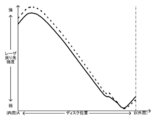
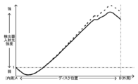
- the intensity of the return light to the laser light source unit 1 and the intensity of the incident light to the photodetector 8 according to the radial direction of the optical disc 19 are shown in FIGS. 2 and 3, respectively.
- the maximum value of the intensity of the return light to the laser light source unit 1 in the optical pickup device of the present embodiment indicated by the solid line is higher than that in the case of the optical pickup device of FIG. It is getting smaller.
- the fluctuation range of the intensity of the incident light to the photodetector 8 in the optical pickup device of the present embodiment indicated by the solid line is that of the optical pickup device of FIG. 7 indicated by the broken line. It is smaller than the case.
- the optical pickup device shown in FIG. 4 includes a polarizing beam splitter 3 instead of the polarizing beam splitter 13 and a mirror 14 instead of the mirror 4 with respect to the optical pickup device of the first embodiment. It is configured.
- the operation of the optical pickup device in this embodiment will be described. Similar to the first embodiment, the operation of the optical pickup device of the present embodiment with respect to the DVD standard optical disc is the same as the operation of the optical pickup device using the broadband quarter-wave plate shown in FIG. Also, the operation of the optical pickup device of the present embodiment for the CD standard optical disk with sufficiently small fluctuations in birefringence is the same as the operation of the optical pickup device using the narrow-band quarter-wave plate shown in FIG. It is. Therefore, in the following, an operation on the CD standard optical disc 19 having a large variation in birefringence will be described.
- the laser light source unit 1 selects and emits laser light having a wavelength ⁇ 2.
- the laser light emitted from the laser light source unit 1 is split into a main beam and a sub beam by the diffraction grating 2 and then enters the polarization beam splitter 3 as S-polarized light, for example.
- the polarization beam splitter 3 reflects most of the S-polarized component contained in the laser light having the wavelength ⁇ 2, and transmits a part of the P-polarized component. Therefore, the polarization beam splitter 3 reflects most of the laser light incident through the diffraction grating 2, and the reflected laser light is incident on the mirror 14 and further reflected.
- the laser light reflected by the mirror 14 is converted into parallel light by the collimator lens 5 and then enters the quarter-wave plate 16.
- the quarter-wave plate 16 converts the laser beam incident through the collimator lens 5 from S-polarized light to elliptically polarized light E1, and the objective lens 7 condenses the elliptically polarized light E1 on the optical disk 19.
- the laser beam reflected by the optical disk 19 enters the quarter-wave plate 16 through the objective lens 7 as elliptically polarized light E2.
- the quarter-wave plate 16 converts the incident laser light from elliptically polarized light E2 to P-polarized light.
- some S-polarized light components remain in the P-polarized light, resulting in some elliptically polarized light P + s.
- the slightly elliptically polarized light P + s enters the mirror 14 via the collimator lens 5.
- the mirror 14 includes, for example, a special polarizing film 14a, the laser beam having the wavelength ⁇ 2 incident through the collimator lens 5 is reflected after the phase of the S polarization component is shifted by approximately 90 °. .
- a special film such as the polarizing film 14a is formed on a desired surface of the mirror 14 based on, for example, a vacuum deposition method or a sputtering method.
- the polarizing film 14a is configured as a thin layer containing at least one substance selected from the group consisting of SiO 2 , ZnO 2 , Ta 2 O 5 , TiO 2 and Ti 2 O 5 , for example.
- the phase of the S-polarized component is approximately 90 ° (about 90 ° ⁇ 15 ° with respect to the incident laser light having the wavelength ⁇ 2, Reflected in a shifted state (preferably about 90 ° ⁇ 5 °). Therefore, the mirror 14 reduces the S-polarized light component from some elliptically polarized light P + s by setting the phase difference between the P-polarized light component and the S-polarized light component to approximately 90 °, and makes the light substantially linearly polarized light (approximately P-polarized light). Further, the laser beam reflected by the mirror 14 enters the polarization beam splitter 3. Further, the polarization beam splitter 3 transmits a part of the P-polarized component with respect to the incident laser light having the wavelength ⁇ 2.
- the ratio of the laser beam having the wavelength ⁇ 2 in the return path that passes through the polarization beam splitter 3 and enters the photodetector 8 is high, and the ratio that is reflected by the polarization beam splitter 3 and returns to the laser light source unit 1 is low.
- the photodetector 8 detects the laser beam that has entered through the polarization beam splitter 3.
- the laser light having the wavelength ⁇ 2 incident on the mirror 14 does not include the P-polarized component, and therefore the laser light reflected by the mirror 14 remains the S-polarized light.
- the optical pickup device of this embodiment shifts the phase of the S-polarized light component by about 90 ° by the mirror 14 with respect to the laser light having the wavelength ⁇ 2 in the return path, and returns light to the laser light source unit 1. Is reduced.
- the 1 ⁇ 4 wavelength plate 16 is disposed between the light separation unit including the polarization beam splitter and the mirror and the objective lens 7, and linearly polarized light Conversion to and from elliptically polarized light is performed on the objective lens 7 side from the light separation unit. Therefore, the phase shift with respect to the laser beam having the wavelength ⁇ 2 in the return path may be performed by either the polarization beam splitter or the mirror. Further, the polarization beam splitter and the mirror may shift the phase, respectively, so that the phases of some S-polarized components are shifted by approximately 90 ° in total.
- the laser light having the wavelength ⁇ 1 or ⁇ 2 selectively emitted from the laser light source unit 1 is used as the objective.
- a narrow-band quarter-wave plate 16 corresponding to the wavelength ⁇ 1 is disposed between the objective lens 7 and a light separation unit that guides the laser light reflected to the lens 7 to the optical detector 8 and the return path.
- the slightly elliptically polarized light P + s is changed to the S-polarized light.
- a component can be reduced and it can be set as substantially P polarized light.
- the S-polarized light component can be reduced by the polarization beam splitter 13 alone by shifting the phase of the laser beam having the wavelength ⁇ 2 in the return path by approximately 90 ° by the polarization beam splitter 13. .
- the S-polarized light component can be reduced by the mirror 14 alone by shifting the phase of the laser light having the wavelength ⁇ 2 in the return path by approximately 90 ° by the mirror 14.
- the polarization beam splitter and the mirror each shift the phase, and the phase of the S-polarized component is shifted by approximately 90 ° in total, thereby adjusting the phase difference between the P-polarized component and the S-polarized component, etc. Design can be done flexibly.
- the optical pickup device corresponds to the optical discs of the DVD standard and the CD standard
- the laser light source unit 1 includes the laser light source for each standard, but is not limited thereto.
- the optical pickup device further corresponds to, for example, a BD (Blu-ray Disc) (registered trademark) optical disc using a blue-violet laser beam having a wavelength of 405 nm
- the laser light source unit 1 further includes a laser light source for the BD standard. May be included.
- a polarization beam splitter 13 and / or a mirror 14 is used as the light separation unit, and for example, a half mirror (Half Mirror) and / or a reflect mirror that reflects part of the laser light and transmits part of the laser light.
- a mirror such as (Reflect Mirror) may be included in the optical path of the optical pickup device.
- a mirror such as a half mirror and / or a reflect mirror that reflects part of the laser light and transmits part of the laser light is used instead of the polarization beam splitter 13 and / or the mirror 14. May be.
- the polarization beam splitter 13 and / or the mirror 14 and a mirror such as a half mirror and / or a reflect mirror may be used.
Landscapes
- Physics & Mathematics (AREA)
- Optics & Photonics (AREA)
- Optical Head (AREA)
- Polarising Elements (AREA)
Abstract
【課題】 狭帯域の1/4波長板を用いた場合のレーザ光源部への戻り光を低減する。 【解決手段】 第1または第2の波長のレーザ光を選択的に出射するレーザ光源部と、レーザ光源部から出射されたレーザ光を光記録媒体上に集光する対物レンズと、光記録媒体で反射されたレーザ光を検出する光検出器と、レーザ光源部から出射されたレーザ光を対物レンズに導くとともに、光記録媒体で反射されたレーザ光を光検出器に導く光分離部と、光分離部を介して入射する第1の波長のレーザ光を直線偏光から円偏光に変換するとともに、光分離部を介して入射する第2の波長のレーザ光を直線偏光から楕円偏光に変換する1/4波長板と、を有し、レーザ光源部から出射された第2の波長のレーザ光は、第1の直線偏光として光分離部に入射し、光分離部は、1/4波長板を介して入射する第2の波長のレーザ光に対して、第1の直線偏光の成分を低減するように位相をシフトさせる。
Description
本発明は、光ピックアップ装置に関する。
近年、光ディスク(光記録媒体)に対して信号の読み出しや書き込みを行う光ピックアップ装置には、規格が異なる複数の光ディスクに対応可能なものもある。
例えば、特許文献1では、波長650nm帯の赤色レーザ光を用いるDVD(登録商標)(Digital Versatile Disc)規格および波長780nm帯の赤外線レーザ光を用いるCD(Compact Disc)(商標)規格に対応し、反射光を検出する光検出器を共通化した光ピックアップ装置(光ヘッド装置)が開示されている。また、例えば、特許文献2では、波長650nm帯のレーザ光源と波長780nm帯のレーザ光源とを同一のパッケージ内に設けた2波長マルチレーザ光源を用いて、DVD規格およびCD規格の光ディスクに対応可能な光ピックアップ装置が開示されている。
このようにして、光検出器やレーザ光源などを共通化して部品点数を削減することによって、光ピックアップ装置の低コスト化や、小型化、製造の容易化などを図ることができる。
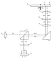
ここで、DVD規格およびCD規格に対応し、光検出器やレーザ光源などを共通化した光ピックアップ装置の構成の一例を図5に示す。なお、図5において、レーザ光源部1は、例えば2波長マルチレーザ光源として構成されており、DVD規格用の波長λ1(=650nm)またはCD規格用の波長λ2(=780nm)のレーザ光を選択的に出射する。
レーザ光源部1から出射されたレーザ光は、回折格子2を介して、例えばS偏光として偏光ビームスプリッタ3に入射する。また、当該S偏光は、偏光ビームスプリッタ3およびミラー4で反射され、コリメータレンズ5を介して1/4波長板6に入射し、円偏光C1(例えば右円偏光)に変換されたうえで、対物レンズ7によって光ディスク9上に集光される。さらに、光ディスク9で反射されたレーザ光は、C1と反対方向の円偏光C2(例えば左円偏光)として、対物レンズ7を介して1/4波長板6に入射する。そして、当該円偏光C2は、1/4波長板6によってS偏光と直交するP偏光に変換されたうえで、ミラー4で反射され、偏光ビームスプリッタ3を透過して光検出器8に入射する。
このような光ピックアップ装置では、一般に、1/4波長板6として、波長λ1ないしλ2のレーザ光に対して直線偏光を円偏光に変換することができる広帯域の1/4波長板が用いられる。一方、光ピックアップ装置のさらなる低コスト化のため、狭帯域の1/4波長板を用いる場合には、より記録密度が高いDVD規格の波長λ1に対応する1/4波長板を用いることが望ましい。
当該狭帯域の1/4波長板は、波長λ1付近のレーザ光に対しては、広帯域の1/4波長板6と同様に、S偏光を円偏光C1に変換することができる。一方、波長λ2のレーザ光に対しては、図6に示すように、S偏光を楕円偏光E1(例えば右楕円偏光)に変換することとなる。この場合、光ディスク9で反射されたレーザ光は、E1と反対方向の楕円偏光E2(例えば左楕円偏光)として、対物レンズ7を介して狭帯域の1/4波長板16に入射する。そして、当該楕円偏光E2は、1/4波長板16によってP偏光に変換される。
しかしながら、狭帯域の1/4波長板16を用いた光ピックアップ装置では、光ディスクの複屈折の変動が大きい場合、当該複屈折の影響によって、図7に示すように、1/4波長板16によって変換されたP偏光に若干のS偏光成分が残存してしまう場合がある。この場合、偏光ビームスプリッタ3には、P偏光に若干のS偏光成分が残存した若干の楕円偏光(図7において、「P+s」と記載)が入射し、当該若干のS偏光成分は、偏光ビームスプリッタ3で反射され、レーザ光源部1に戻ることとなる。そのため、当該レーザ光源部1への戻り光の影響によって、光ピックアップ装置の読み出しや書き込みの性能が低下してしまう。
前述した課題を解決する主たる本発明は、第1および第2の波長のレーザ光をそれぞれ出射する第1および第2のレーザ光源を含み、前記第1または第2の波長のレーザ光を選択的に出射するレーザ光源部と、前記レーザ光源部から出射されたレーザ光を光記録媒体上に集光する対物レンズと、前記光記録媒体で反射されたレーザ光を検出する光検出器と、前記レーザ光源部から出射されたレーザ光と前記光記録媒体で反射されたレーザ光とを波長および偏光方向に応じて分離して、前記レーザ光源部から出射されたレーザ光を前記対物レンズに導くとともに、前記光記録媒体で反射されたレーザ光を前記光検出器に導く光分離部と、前記光分離部と前記対物レンズとの間に配置され、前記光分離部を介して入射する前記第1の波長のレーザ光を直線偏光から円偏光に変換するとともに、前記光分離部を介して入射する前記第2の波長のレーザ光を直線偏光から楕円偏光に変換する1/4波長板と、を有し、前記レーザ光源部から出射された前記第2の波長のレーザ光は、第1の直線偏光として前記光分離部に入射し、前記光分離部は、前記1/4波長板を介して入射する前記第2の波長のレーザ光に対して、前記第1の直線偏光の成分を低減するように位相をシフトさせることを特徴とする光ピックアップ装置である。
本発明の他の特徴については、添付図面及び本明細書の記載により明らかとなる。
本発明によれば、狭帯域の1/4波長板を用いた場合のレーザ光源部への戻り光を低減することができる。
本明細書および添付図面の記載により、少なくとも以下の事項が明らかとなる。
<第1実施形態>
===光ピックアップ装置の構成===
以下、図1を参照して、本発明の第1の実施形態における光ピックアップ装置の構成について説明する。
===光ピックアップ装置の構成===
以下、図1を参照して、本発明の第1の実施形態における光ピックアップ装置の構成について説明する。
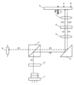
図1に示されている光ピックアップ装置は、レーザ光源部1、回折格子2、偏光ビームスプリッタ13(偏光部材)、ミラー4、コリメータレンズ5、1/4波長板16、対物レンズ7、および光検出器8を含んで構成されている。また、当該光ピックアップ装置は、例えばDVD規格およびCD規格のように、規格が異なる複数の光ディスクに対して信号の読み出しや書き込みを行うことができ、図1においては、CD規格の光ディスク19が読み出し対象としてセットされた場合を示している。
なお、本実施形態では、偏光ビームスプリッタ13およびミラー4が光分離部に相当する。また、1/4波長板16としては、DVD規格の波長λ1(第1の波長)に対応する狭帯域の1/4波長板が用いられている。そのため、1/4波長板16は、波長λ1付近のレーザ光に対しては、直線偏光を円偏光に変換する一方、CD規格用の波長λ2(第2の波長)のレーザ光に対しては、直線偏光を楕円偏光に変換する。
レーザ光源部1は、波長λ1およびλ2のレーザ光をそれぞれ出射する(第1および第2の)レーザ光源を含み、セットされた光ディスクに応じて、波長λ1またはλ2のレーザ光を選択的に出射するように構成されている。
なお、以下においては、例えば特許文献2の図9と同様に、レーザ光源部1として、波長λ1のレーザ光源と波長λ2のレーザ光源とを同一のパッケージ内に設けた2波長マルチレーザ光源を用いた場合について説明する。しかしながら、例えば特許文献1の図1と同様に、レーザ光源部1を各波長のレーザ光を出射する別個のレーザ光源で構成し、各レーザ光に対応して回折格子や偏光ビームスプリッタを設けてもよい。この場合、図1においては、波長λ2のレーザ光に対応する回折格子2および偏光ビームスプリッタ13が示されており、波長λ1のレーザ光に対応する回折格子や偏光ビームスプリッタは、図示されていない。
図1において、実線の矢印は、レーザ光源部1から出射されたレーザ光が光ディスク19上に集光されるまでの光路(往路)を示し、破線の矢印は、光ディスク19で反射されたレーザ光が光検出器8に入射するまでの光路(復路)を示している。
往路において、回折格子2および偏光ビームスプリッタ13は、レーザ光源部1から出射されたレーザ光が回折格子2を介して偏光ビームスプリッタ13に入射するように配置されている。また、偏光ビームスプリッタ13およびミラー4は、偏光ビームスプリッタ13で反射されたレーザ光がミラー4に入射するように配置されている。そして、ミラー4、コリメータレンズ5、1/4波長板16、および対物レンズ7は、ミラー4で反射されたレーザ光がコリメータレンズ5、1/4波長板16、および対物レンズ7を介して光ディスク19上に集光されるように配置されている。
一方、復路において、光ディスク19で反射されたレーザ光は、対物レンズ7、1/4波長板16、およびコリメータレンズ5を介して再びミラー4に入射している。そして、ミラー4、偏光ビームスプリッタ13、および光検出器8は、ミラー4で反射されたレーザ光が偏光ビームスプリッタ13に入射し、さらに、偏光ビームスプリッタ13を透過したレーザ光が光検出器8に入射するように配置されている。
===光ピックアップ装置の動作===
次に、本実施形態における光ピックアップ装置の動作について説明する。
前述したように、本実施形態では、1/4波長板16として、波長λ1に対応する狭帯域の1/4波長板が用いられている。そのため、DVD規格の光ディスクに対する本実施形態の光ピックアップ装置の動作は、図5に示した、広帯域の1/4波長板を用いた光ピックアップ装置の動作と同様である。また、複屈折の変動が十分に小さいCD規格の光ディスクに対する本実施形態の光ピックアップ装置の動作は、図6に示した、狭帯域の1/4波長板を用いた光ピックアップ装置の動作と同様である。そこで、以下においては、複屈折の変動が大きいCD規格の光ディスク19に対する動作について説明する。
CD規格の光ディスク19が読み出し対象としてセットされている場合、レーザ光源部1は、波長λ2のレーザ光を選択して出射する。また、レーザ光源部1から出射されたレーザ光は、回折格子2によってメインビーム(0次回折光)およびサブビーム(例えば±1次回折光)に分割されたうえで、例えばS偏光(第1の直線偏光)として偏光ビームスプリッタ13に入射する。
偏光ビームスプリッタ13は、波長λ2のレーザ光に含まれるS偏光成分の大部分(例えば90~100%程度)を反射するとともに、P偏光(第2の直線偏光)成分の一部分(例えば20~30%程度)を透過させる。したがって、偏光ビームスプリッタ13は、回折格子2を介して入射したレーザ光の大部分を反射し、当該反射されたレーザ光は、ミラー4に入射して、さらに反射される。
ミラー4で反射されたレーザ光は、コリメータレンズ5によって平行光に変換されたうえで、1/4波長板16に入射する。また、1/4波長板16は、コリメータレンズ5を介して入射したレーザ光をS偏光から楕円偏光E1(例えば右楕円偏光)に変換し、対物レンズ7は、当該楕円偏光E1を光ディスク19上に集光する。
一方、光ディスク19で反射されたレーザ光は、E1と反対方向の楕円偏光E2(例えば左楕円偏光)として、対物レンズ7を介して1/4波長板16に入射する。また、1/4波長板16は、当該入射したレーザ光を楕円偏光E2からP偏光に変換する。しかしながら、光ディスク19の複屈折の影響によって、実際には、当該P偏光に若干のS偏光成分が残存してしまい、若干の楕円偏光P+sとなる。そして、当該若干の楕円偏光P+sは、コリメータレンズ5を介してミラー4に入射して、さらに反射される。
ミラー4で反射されたレーザ光は、偏光ビームスプリッタ13に入射する。また、偏光ビームスプリッタ13は、例えば特殊な偏光性皮膜13aを備えているので、当該入射した波長λ2のレーザ光に対して、P偏光成分の一部分を透過させるとともに、S偏光成分の位相を略90°(90°±15°程度、好ましくは90°±5°程度)シフトさせる。偏光性皮膜13aなどの特殊な膜は、例えば、真空蒸着法、スパッタリング法などに基づいて、偏光ビームスプリッタ13の所望の面に形成される。偏光性皮膜13aは、例えば、SiO2、ZnO2、Ta2O5、TiO2およびTi2O5からなる群から選択される少なくとも一種以上の物質を含有する薄層として構成される。このように、偏光ビームスプリッタ13に例えば特殊な偏光性皮膜13aが設けられているので、入射された波長λ2のレーザ光に対して、P偏光成分の一部分が透過されるとともに、S偏光成分の位相が略90°シフトされる。したがって、偏光ビームスプリッタ13は、P偏光成分とS偏光成分との位相差を略90°とすることによって、若干の楕円偏光P+sからS偏光成分を低減し、略直線偏光(略P偏光)とする。
そのため、復路における波長λ2のレーザ光のうち、偏光ビームスプリッタ13を透過して光検出器8に入射する割合が高くなるとともに、偏光ビームスプリッタ13で反射されてレーザ光源部1に戻る割合が低くなる。そして、光検出器8は、偏光ビームスプリッタ13を透過して入射したレーザ光を検出する。なお、往路においては、偏光ビームスプリッタ13に入射する波長λ2のレーザ光には、P偏光成分が含まれないため、偏光ビームスプリッタ13で反射されたレーザ光は、S偏光のままである。
このようにして、本実施形態の光ピックアップ装置は、復路における波長λ2のレーザ光に対して、偏光ビームスプリッタ13によって若干のS偏光成分の位相を略90°シフトさせ、レーザ光源部1への戻り光を低減している。
ここで、一例として、光ディスク19の径方向に応じた、レーザ光源部1への戻り光の強度および光検出器8への入射光の強度を、それぞれ図2および図3に示す。図2から明らかなように、実線で示された本実施形態の光ピックアップ装置におけるレーザ光源部1への戻り光の強度の最大値は、破線で示された図7の光ピックアップ装置の場合より小さくなっている。また、図3から明らかなように、実線で示された本実施形態の光ピックアップ装置における光検出器8への入射光の強度の変動幅は、破線で示された図7の光ピックアップ装置の場合より小さくなっている。
<第2実施形態>
===光ピックアップ装置の構成および動作===
以下、図4を参照して、本発明の第2の実施形態における光ピックアップ装置の構成について説明する。
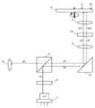
図4に示されている光ピックアップ装置は、第1実施形態の光ピックアップ装置に対して、偏光ビームスプリッタ13の代わりに偏光ビームスプリッタ3を含み、また、ミラー4の代わりにミラー14を含んで構成されている。
===光ピックアップ装置の構成および動作===
以下、図4を参照して、本発明の第2の実施形態における光ピックアップ装置の構成について説明する。
図4に示されている光ピックアップ装置は、第1実施形態の光ピックアップ装置に対して、偏光ビームスプリッタ13の代わりに偏光ビームスプリッタ3を含み、また、ミラー4の代わりにミラー14を含んで構成されている。
次に、本実施形態における光ピックアップ装置の動作について説明する。
第1実施形態と同様に、DVD規格の光ディスクに対する本実施形態の光ピックアップ装置の動作は、図5に示した、広帯域の1/4波長板を用いた光ピックアップ装置の動作と同様である。また、複屈折の変動が十分に小さいCD規格の光ディスクに対する本実施形態の光ピックアップ装置の動作は、図6に示した、狭帯域の1/4波長板を用いた光ピックアップ装置の動作と同様である。そこで、以下においては、複屈折の変動が大きいCD規格の光ディスク19に対する動作について説明する。
第1実施形態と同様に、DVD規格の光ディスクに対する本実施形態の光ピックアップ装置の動作は、図5に示した、広帯域の1/4波長板を用いた光ピックアップ装置の動作と同様である。また、複屈折の変動が十分に小さいCD規格の光ディスクに対する本実施形態の光ピックアップ装置の動作は、図6に示した、狭帯域の1/4波長板を用いた光ピックアップ装置の動作と同様である。そこで、以下においては、複屈折の変動が大きいCD規格の光ディスク19に対する動作について説明する。
CD規格の光ディスク19が読み出し対象としてセットされている場合、レーザ光源部1は、波長λ2のレーザ光を選択して出射する。また、レーザ光源部1から出射されたレーザ光は、回折格子2によってメインビームおよびサブビームに分割されたうえで、例えばS偏光として偏光ビームスプリッタ3に入射する。
偏光ビームスプリッタ3は、波長λ2のレーザ光に含まれるS偏光成分の大部分を反射するとともに、P偏光成分の一部分を透過させる。したがって、偏光ビームスプリッタ3は、回折格子2を介して入射したレーザ光の大部分を反射し、当該反射されたレーザ光は、ミラー14に入射して、さらに反射される。
ミラー14で反射されたレーザ光は、コリメータレンズ5によって平行光に変換されたうえで、1/4波長板16に入射する。また、1/4波長板16は、コリメータレンズ5を介して入射したレーザ光をS偏光から楕円偏光E1に変換し、対物レンズ7は、当該楕円偏光E1を光ディスク19上に集光する。
一方、光ディスク19で反射されたレーザ光は、楕円偏光E2として、対物レンズ7を介して1/4波長板16に入射する。また、1/4波長板16は、当該入射したレーザ光を楕円偏光E2からP偏光に変換する。しかしながら、光ディスク19の複屈折の影響によって、実際には、当該P偏光に若干のS偏光成分が残存してしまい、若干の楕円偏光P+sとなる。そして、当該若干の楕円偏光P+sは、コリメータレンズ5を介してミラー14に入射する。
ミラー14は、例えば特殊な偏光性皮膜14aを備えているので、コリメータレンズ5を介して入射した波長λ2のレーザ光に対して、S偏光成分の位相を略90°シフトさせたうえで反射する。偏光性皮膜14aなどの特殊な膜は、例えば、真空蒸着法、スパッタリング法などに基づいて、ミラー14の所望の面に形成される。偏光性皮膜14aは、例えば、SiO2、ZnO2、Ta2O5、TiO2およびTi2O5からなる群から選択される少なくとも一種以上の物質を含有する薄層として構成される。このように、ミラー14に例えば特殊な偏光性皮膜14aが設けられているので、入射された波長λ2のレーザ光に対して、S偏光成分の位相が略90°(90°±15°程度、好ましくは90°±5°程度)シフトされた状態で反射される。したがって、ミラー14は、P偏光成分とS偏光成分との位相差を略90°とすることによって、若干の楕円偏光P+sからS偏光成分を低減し、略直線偏光(略P偏光)とする。また、ミラー14で反射されたレーザ光は、偏光ビームスプリッタ3に入射する。さらに、偏光ビームスプリッタ3は、当該入射した波長λ2のレーザ光に対して、P偏光成分の一部分を透過させる。
そのため、復路における波長λ2のレーザ光のうち、偏光ビームスプリッタ3を透過して光検出器8に入射する割合が高くなるとともに、偏光ビームスプリッタ3で反射されてレーザ光源部1に戻る割合が低くなる。そして、光検出器8は、偏光ビームスプリッタ3を透過して入射したレーザ光を検出する。なお、往路においては、ミラー14に入射する波長λ2のレーザ光には、P偏光成分が含まれないため、ミラー14で反射されたレーザ光は、S偏光のままである。
このようにして、本実施形態の光ピックアップ装置は、復路における波長λ2のレーザ光に対して、ミラー14によって若干のS偏光成分の位相を略90°シフトさせ、レーザ光源部1への戻り光を低減している。
以上のように、第1および第2実施形態の光ピックアップ装置では、1/4波長板16は、偏光ビームスプリッタおよびミラーを含む光分離部と対物レンズ7との間に配置され、直線偏光と楕円偏光との間の変換は、光分離部より対物レンズ7側で行われている。そのため、復路における波長λ2のレーザ光に対する位相のシフトは、偏光ビームスプリッタおよびミラーのいずれによって行ってもよい。さらに、偏光ビームスプリッタおよびミラーがそれぞれ位相のシフトを行い、若干のS偏光成分の位相を合計で略90°シフトさせる構成とすることもできる。
前述したように、図1および図4に示した、DVD規格およびCD規格の光ディスクに対応可能な光ピックアップ装置において、レーザ光源部1から選択的に出射された波長λ1またはλ2のレーザ光を対物レンズ7に導くとともに光ディスクで反射されたレーザ光を光検出器8に導く光分離部と、対物レンズ7との間に波長λ1に対応する狭帯域の1/4波長板16を配置し、復路における波長λ2のレーザ光の位相を光分離部においてシフトさせてS偏光成分を低減することによって、狭帯域の1/4波長板16を用いた場合のレーザ光源部1への戻り光を低減することができる。
また、復路における波長λ2のレーザ光に対してS偏光成分の位相をシフトさせて、P偏光成分とS偏光成分との位相差を略90°とすることによって、若干の楕円偏光P+sからS偏光成分を低減し、略P偏光とすることができる。
また、図1に示した光ピックアップ装置において、復路における波長λ2のレーザ光の位相を偏光ビームスプリッタ13によって略90°シフトさせることによって、偏光ビームスプリッタ13単体でS偏光成分を低減することができる。
また、図4に示した光ピックアップ装置において、復路における波長λ2のレーザ光の位相をミラー14によって略90°シフトさせることによって、ミラー14単体でS偏光成分を低減することができる。
また、偏光ビームスプリッタおよびミラーがそれぞれ位相のシフトを行い、S偏光成分の位相を合計で略90°シフトさせることによって、P偏光成分とS偏光成分との位相差を調整する位相差板などの設計を柔軟に行うことができる。
なお、上記実施形態は、本発明の理解を容易にするためのものであり、本発明を限定して解釈するためのものではない。本発明は、その趣旨を逸脱することなく、変更、改良され得るとともに、本発明にはその等価物も含まれる。
上記実施形態では、光ピックアップ装置は、DVD規格およびCD規格の光ディスクに対応し、レーザ光源部1は、各規格用のレーザ光源を含んでいるが、これに限定されるものではない。光ピックアップ装置は、例えば、波長405nm帯の青紫色レーザ光を用いるBD(Blu-ray Disc)(登録商標)規格の光ディスクにさらに対応し、レーザ光源部1は、BD規格用のレーザ光源をさらに含んでいてもよい。また、光分離部として、偏光ビームスプリッタ13および/またはミラー14が用いられると共に、例えばレーザ光の一部を反射させレーザ光の一部を透過させるハーフミラー(Half Mirror)および/またはレフレクトミラー(Reflect Mirror)等のミラーが、光ピックアップ装置の光路に含まれていてもよい。また、光分離部として、偏光ビームスプリッタ13および/またはミラー14に代えて、例えばレーザ光の一部を反射させレーザ光の一部を透過させるハーフミラーおよび/またはレフレクトミラー等のミラーが用いられてもよい。また、光分離部として、例えば、偏光ビームスプリッタ13および/またはミラー14と、ハーフミラーおよび/またはレフレクトミラー等のミラーと、が用いられてもよい。
1 レーザ光源部
2 回折格子
3、13 偏光ビームスプリッタ
4、14 ミラー
5 コリメータレンズ
6、16 1/4波長板
7 対物レンズ
8 光検出器
9、19 光ディスク
13a、14a 皮膜
2 回折格子
3、13 偏光ビームスプリッタ
4、14 ミラー
5 コリメータレンズ
6、16 1/4波長板
7 対物レンズ
8 光検出器
9、19 光ディスク
13a、14a 皮膜
Claims (5)
- 第1および第2の波長のレーザ光をそれぞれ出射する第1および第2のレーザ光源を含み、前記第1または第2の波長のレーザ光を選択的に出射するレーザ光源部と、
前記レーザ光源部から出射されたレーザ光を光記録媒体上に集光する対物レンズと、
前記光記録媒体で反射されたレーザ光を検出する光検出器と、
前記レーザ光源部から出射されたレーザ光と前記光記録媒体で反射されたレーザ光とを波長および偏光方向に応じて分離して、前記レーザ光源部から出射されたレーザ光を前記対物レンズに導くとともに、前記光記録媒体で反射されたレーザ光を前記光検出器に導く光分離部と、
前記光分離部と前記対物レンズとの間に配置され、前記光分離部を介して入射する前記第1の波長のレーザ光を直線偏光から円偏光に変換するとともに、前記光分離部を介して入射する前記第2の波長のレーザ光を直線偏光から楕円偏光に変換する1/4波長板と、
を有し、
前記レーザ光源部から出射された前記第2の波長のレーザ光は、第1の直線偏光として前記光分離部に入射し、
前記光分離部は、前記1/4波長板を介して入射する前記第2の波長のレーザ光に対して、前記第1の直線偏光の成分を低減するように位相をシフトさせることを特徴とする光ピックアップ装置。 - 前記光分離部は、前記1/4波長板を介して入射する前記第2の波長のレーザ光に対して、前記第1の直線偏光の成分の位相を略90°シフトさせることを特徴とする請求項1に記載の光ピックアップ装置。
- 前記光分離部は、前記第2の波長のレーザ光に含まれる前記第1の直線偏光の成分の大部分を反射するとともに、前記第1の直線偏光と直交する第2の直線偏光の成分の一部分を透過させる偏光部材を含み、
前記レーザ光源部から出射され、前記偏光部材で反射された前記第2の波長のレーザ光を前記対物レンズに導くとともに、前記光記録媒体で反射され、前記偏光部材を透過した前記第2の波長のレーザ光を前記光検出器に導き、
前記偏光部材は、前記1/4波長板を介して入射する前記第2の波長のレーザ光に対して、前記第1の直線偏光の成分を低減するように位相をシフトさせることを特徴とする請求項1又は2に記載の光ピックアップ装置。 - 前記光分離部は、前記1/4波長板を介して入射する前記第2の波長のレーザ光を反射するミラーを含み、
前記ミラーは、前記1/4波長板を介して入射する前記第2の波長のレーザ光に対して、前記第1の直線偏光の成分を低減するように位相をシフトさせることを特徴とする請求項1又は2に記載の光ピックアップ装置。 - 前記光分離部は、
前記第2の波長のレーザ光に含まれる前記第1の直線偏光の成分の大部分を反射するとともに、前記第1の直線偏光と直交する第2の直線偏光の成分の一部分を透過させる偏光部材と、
前記偏光部材で反射された前記第2の波長のレーザ光を反射して前記対物レンズに導くとともに、前記1/4波長板を介して入射する前記第2の波長のレーザ光を反射して前記偏光部材に導くミラーと、
を含み、
前記偏光部材および前記ミラーは、前記1/4波長板を介して入射する前記第2の波長のレーザ光に対して、前記第1の直線偏光の成分の位相を合計で略90°シフトさせることを特徴とする請求項1に記載の光ピックアップ装置。
Priority Applications (2)
| Application Number | Priority Date | Filing Date | Title |
|---|---|---|---|
| CN2011800366972A CN103026410A (zh) | 2010-09-08 | 2011-09-06 | 光拾取装置 |
| US13/790,686 US20130188466A1 (en) | 2010-09-08 | 2013-03-08 | Optical pickup apparatus |
Applications Claiming Priority (2)
| Application Number | Priority Date | Filing Date | Title |
|---|---|---|---|
| JP2010-201215 | 2010-09-08 | ||
| JP2010201215A JP2013242932A (ja) | 2010-09-08 | 2010-09-08 | 光ピックアップ装置 |
Related Child Applications (1)
| Application Number | Title | Priority Date | Filing Date |
|---|---|---|---|
| US13/790,686 Continuation US20130188466A1 (en) | 2010-09-08 | 2013-03-08 | Optical pickup apparatus |
Publications (1)
| Publication Number | Publication Date |
|---|---|
| WO2012033067A1 true WO2012033067A1 (ja) | 2012-03-15 |
Family
ID=45810666
Family Applications (1)
| Application Number | Title | Priority Date | Filing Date |
|---|---|---|---|
| PCT/JP2011/070201 Ceased WO2012033067A1 (ja) | 2010-09-08 | 2011-09-06 | 光ピックアップ装置 |
Country Status (4)
| Country | Link |
|---|---|
| US (1) | US20130188466A1 (ja) |
| JP (1) | JP2013242932A (ja) |
| CN (1) | CN103026410A (ja) |
| WO (1) | WO2012033067A1 (ja) |
Cited By (1)
| Publication number | Priority date | Publication date | Assignee | Title |
|---|---|---|---|---|
| WO2013183439A1 (ja) * | 2012-06-05 | 2013-12-12 | 三洋電機株式会社 | 光ピックアップ装置 |
Families Citing this family (1)
| Publication number | Priority date | Publication date | Assignee | Title |
|---|---|---|---|---|
| CN113834783B (zh) * | 2021-09-18 | 2024-06-18 | 王红珍 | 一种检测半导体电子器件的装置及方法 |
Citations (4)
| Publication number | Priority date | Publication date | Assignee | Title |
|---|---|---|---|---|
| JP2004192756A (ja) * | 2002-12-13 | 2004-07-08 | Ricoh Co Ltd | 光ピックアップ装置 |
| JP2009104714A (ja) * | 2007-10-23 | 2009-05-14 | Samsung Electronics Co Ltd | 光ピックアップ装置及び光情報記録再生装置 |
| JP2009129514A (ja) * | 2007-11-26 | 2009-06-11 | Nidec Sankyo Corp | 光ヘッド装置 |
| JP2009259341A (ja) * | 2008-04-17 | 2009-11-05 | Victor Co Of Japan Ltd | 光ピックアップ装置 |
Family Cites Families (4)
| Publication number | Priority date | Publication date | Assignee | Title |
|---|---|---|---|---|
| US7609606B2 (en) * | 2004-12-28 | 2009-10-27 | Sanyo Electric Co., Ltd. | Optical pickup device |
| WO2009017037A1 (ja) * | 2007-07-27 | 2009-02-05 | Asahi Glass Co., Ltd. | 位相差素子および光ヘッド装置 |
| JP2010238274A (ja) * | 2009-03-30 | 2010-10-21 | Sanyo Electric Co Ltd | 光ピックアップ装置 |
| KR20110097260A (ko) * | 2010-02-25 | 2011-08-31 | 삼성전자주식회사 | 광 형성장치 |
-
2010
- 2010-09-08 JP JP2010201215A patent/JP2013242932A/ja active Pending
-
2011
- 2011-09-06 WO PCT/JP2011/070201 patent/WO2012033067A1/ja not_active Ceased
- 2011-09-06 CN CN2011800366972A patent/CN103026410A/zh active Pending
-
2013
- 2013-03-08 US US13/790,686 patent/US20130188466A1/en not_active Abandoned
Patent Citations (4)
| Publication number | Priority date | Publication date | Assignee | Title |
|---|---|---|---|---|
| JP2004192756A (ja) * | 2002-12-13 | 2004-07-08 | Ricoh Co Ltd | 光ピックアップ装置 |
| JP2009104714A (ja) * | 2007-10-23 | 2009-05-14 | Samsung Electronics Co Ltd | 光ピックアップ装置及び光情報記録再生装置 |
| JP2009129514A (ja) * | 2007-11-26 | 2009-06-11 | Nidec Sankyo Corp | 光ヘッド装置 |
| JP2009259341A (ja) * | 2008-04-17 | 2009-11-05 | Victor Co Of Japan Ltd | 光ピックアップ装置 |
Cited By (1)
| Publication number | Priority date | Publication date | Assignee | Title |
|---|---|---|---|---|
| WO2013183439A1 (ja) * | 2012-06-05 | 2013-12-12 | 三洋電機株式会社 | 光ピックアップ装置 |
Also Published As
| Publication number | Publication date |
|---|---|
| US20130188466A1 (en) | 2013-07-25 |
| JP2013242932A (ja) | 2013-12-05 |
| CN103026410A (zh) | 2013-04-03 |
Similar Documents
| Publication | Publication Date | Title |
|---|---|---|
| KR20060086746A (ko) | 광픽업 장치 | |
| US7710849B2 (en) | Optical head device and optical information recording or reproducing device | |
| WO2007142179A1 (ja) | 四分の一波長板及び光ピックアップ装置 | |
| JP2013242932A (ja) | 光ピックアップ装置 | |
| JP4380438B2 (ja) | 光ディスク装置 | |
| JP2005327338A (ja) | 光ピックアップ及びディスク状光学記録媒体記録再生装置 | |
| US20080055734A1 (en) | Optical pickup and optical disc device | |
| JP4608545B2 (ja) | 光ピックアップ装置及び情報記録再生装置 | |
| JP5382124B2 (ja) | 光ピックアップ装置 | |
| JPWO2006106725A1 (ja) | 光ピックアップおよび光ディスク装置 | |
| KR100915490B1 (ko) | 광 픽업 장치, 광 디스크 장치 및 레이저 출력기 | |
| JP5046939B2 (ja) | 光ピックアップ装置 | |
| JP3970254B2 (ja) | 光ピックアップ装置 | |
| JP2010003331A (ja) | 光ヘッド装置 | |
| JP4876814B2 (ja) | 位相差素子および光ヘッド装置 | |
| KR100600587B1 (ko) | 광픽업 장치 | |
| JP3963904B2 (ja) | 光ピックアップ装置 | |
| JP2008257797A (ja) | 光ピックアップ装置及び光ディスク装置 | |
| JP2008034070A (ja) | 光ピックアップ装置およびその制御方法、情報記録再生装置 | |
| JP2011227944A (ja) | 光ヘッド装置 | |
| KR20110097260A (ko) | 광 형성장치 | |
| JP2007035114A (ja) | 偏光分離素子と光ピックアップ装置 | |
| JP2006155707A (ja) | 光ピックアップ装置および光学素子 | |
| WO2013183439A1 (ja) | 光ピックアップ装置 | |
| JP2009070526A (ja) | 開口フィルタおよび光ピックアップ |
Legal Events
| Date | Code | Title | Description |
|---|---|---|---|
| WWE | Wipo information: entry into national phase |
Ref document number: 201180036697.2 Country of ref document: CN |
|
| 121 | Ep: the epo has been informed by wipo that ep was designated in this application |
Ref document number: 11823542 Country of ref document: EP Kind code of ref document: A1 |
|
| NENP | Non-entry into the national phase |
Ref country code: DE |
|
| 122 | Ep: pct application non-entry in european phase |
Ref document number: 11823542 Country of ref document: EP Kind code of ref document: A1 |
|
| NENP | Non-entry into the national phase |
Ref country code: JP |