WO2012029720A1 - 開閉体用のヒンジ装置 - Google Patents
開閉体用のヒンジ装置 Download PDFInfo
- Publication number
- WO2012029720A1 WO2012029720A1 PCT/JP2011/069480 JP2011069480W WO2012029720A1 WO 2012029720 A1 WO2012029720 A1 WO 2012029720A1 JP 2011069480 W JP2011069480 W JP 2011069480W WO 2012029720 A1 WO2012029720 A1 WO 2012029720A1
- Authority
- WO
- WIPO (PCT)
- Prior art keywords
- opening
- closing body
- shaft
- hinge device
- closing
- Prior art date
- Legal status (The legal status is an assumption and is not a legal conclusion. Google has not performed a legal analysis and makes no representation as to the accuracy of the status listed.)
- Ceased
Links
Images





















Classifications
-
- E—FIXED CONSTRUCTIONS
- E05—LOCKS; KEYS; WINDOW OR DOOR FITTINGS; SAFES
- E05F—DEVICES FOR MOVING WINGS INTO OPEN OR CLOSED POSITION; CHECKS FOR WINGS; WING FITTINGS NOT OTHERWISE PROVIDED FOR, CONCERNED WITH THE FUNCTIONING OF THE WING
- E05F1/00—Closers or openers for wings, not otherwise provided for in this subclass
- E05F1/08—Closers or openers for wings, not otherwise provided for in this subclass spring-actuated, e.g. for horizontally sliding wings
- E05F1/10—Closers or openers for wings, not otherwise provided for in this subclass spring-actuated, e.g. for horizontally sliding wings for swinging wings, e.g. counterbalance
- E05F1/12—Mechanisms in the shape of hinges or pivots, operated by springs
- E05F1/1207—Mechanisms in the shape of hinges or pivots, operated by springs with a coil spring parallel with the pivot axis
- E05F1/1215—Mechanisms in the shape of hinges or pivots, operated by springs with a coil spring parallel with the pivot axis with a canted-coil torsion spring
-
- E—FIXED CONSTRUCTIONS
- E05—LOCKS; KEYS; WINDOW OR DOOR FITTINGS; SAFES
- E05D—HINGES OR SUSPENSION DEVICES FOR DOORS, WINDOWS OR WINGS
- E05D11/00—Additional features or accessories of hinges
- E05D11/10—Devices for preventing movement between relatively-movable hinge parts
- E05D11/1028—Devices for preventing movement between relatively-movable hinge parts for maintaining the hinge in two or more positions, e.g. intermediate or fully open
- E05D11/1078—Devices for preventing movement between relatively-movable hinge parts for maintaining the hinge in two or more positions, e.g. intermediate or fully open the maintaining means acting parallel to the pivot
-
- G—PHYSICS
- G03—PHOTOGRAPHY; CINEMATOGRAPHY; ANALOGOUS TECHNIQUES USING WAVES OTHER THAN OPTICAL WAVES; ELECTROGRAPHY; HOLOGRAPHY
- G03G—ELECTROGRAPHY; ELECTROPHOTOGRAPHY; MAGNETOGRAPHY
- G03G15/00—Apparatus for electrographic processes using a charge pattern
- G03G15/60—Apparatus which relate to the handling of originals
- G03G15/605—Holders for originals or exposure platens
-
- G—PHYSICS
- G03—PHOTOGRAPHY; CINEMATOGRAPHY; ANALOGOUS TECHNIQUES USING WAVES OTHER THAN OPTICAL WAVES; ELECTROGRAPHY; HOLOGRAPHY
- G03G—ELECTROGRAPHY; ELECTROPHOTOGRAPHY; MAGNETOGRAPHY
- G03G21/00—Arrangements not provided for by groups G03G13/00 - G03G19/00, e.g. cleaning, elimination of residual charge
- G03G21/16—Mechanical means for facilitating the maintenance of the apparatus, e.g. modular arrangements
- G03G21/1604—Arrangement or disposition of the entire apparatus
- G03G21/1623—Means to access the interior of the apparatus
- G03G21/1633—Means to access the interior of the apparatus using doors or covers
-
- E—FIXED CONSTRUCTIONS
- E05—LOCKS; KEYS; WINDOW OR DOOR FITTINGS; SAFES
- E05D—HINGES OR SUSPENSION DEVICES FOR DOORS, WINDOWS OR WINGS
- E05D11/00—Additional features or accessories of hinges
- E05D11/08—Friction devices between relatively-movable hinge parts
- E05D11/087—Friction devices between relatively-movable hinge parts with substantially axial friction, e.g. friction disks
-
- E—FIXED CONSTRUCTIONS
- E05—LOCKS; KEYS; WINDOW OR DOOR FITTINGS; SAFES
- E05D—HINGES OR SUSPENSION DEVICES FOR DOORS, WINDOWS OR WINGS
- E05D11/00—Additional features or accessories of hinges
- E05D11/10—Devices for preventing movement between relatively-movable hinge parts
- E05D11/1028—Devices for preventing movement between relatively-movable hinge parts for maintaining the hinge in two or more positions, e.g. intermediate or fully open
- E05D2011/1035—Devices for preventing movement between relatively-movable hinge parts for maintaining the hinge in two or more positions, e.g. intermediate or fully open with circumferential and evenly distributed detents around the pivot-axis
-
- E—FIXED CONSTRUCTIONS
- E05—LOCKS; KEYS; WINDOW OR DOOR FITTINGS; SAFES
- E05Y—INDEXING SCHEME ASSOCIATED WITH SUBCLASSES E05D AND E05F, RELATING TO CONSTRUCTION ELEMENTS, ELECTRIC CONTROL, POWER SUPPLY, POWER SIGNAL OR TRANSMISSION, USER INTERFACES, MOUNTING OR COUPLING, DETAILS, ACCESSORIES, AUXILIARY OPERATIONS NOT OTHERWISE PROVIDED FOR, APPLICATION THEREOF
- E05Y2201/00—Constructional elements; Accessories therefor
- E05Y2201/40—Motors; Magnets; Springs; Weights; Accessories therefor
- E05Y2201/47—Springs
- E05Y2201/484—Torsion springs
-
- E—FIXED CONSTRUCTIONS
- E05—LOCKS; KEYS; WINDOW OR DOOR FITTINGS; SAFES
- E05Y—INDEXING SCHEME ASSOCIATED WITH SUBCLASSES E05D AND E05F, RELATING TO CONSTRUCTION ELEMENTS, ELECTRIC CONTROL, POWER SUPPLY, POWER SIGNAL OR TRANSMISSION, USER INTERFACES, MOUNTING OR COUPLING, DETAILS, ACCESSORIES, AUXILIARY OPERATIONS NOT OTHERWISE PROVIDED FOR, APPLICATION THEREOF
- E05Y2600/00—Mounting or coupling arrangements for elements provided for in this subclass
- E05Y2600/10—Adjustable
- E05Y2600/20—Adjustable with specific transmission movement
-
- E—FIXED CONSTRUCTIONS
- E05—LOCKS; KEYS; WINDOW OR DOOR FITTINGS; SAFES
- E05Y—INDEXING SCHEME ASSOCIATED WITH SUBCLASSES E05D AND E05F, RELATING TO CONSTRUCTION ELEMENTS, ELECTRIC CONTROL, POWER SUPPLY, POWER SIGNAL OR TRANSMISSION, USER INTERFACES, MOUNTING OR COUPLING, DETAILS, ACCESSORIES, AUXILIARY OPERATIONS NOT OTHERWISE PROVIDED FOR, APPLICATION THEREOF
- E05Y2999/00—Subject-matter not otherwise provided for in this subclass
Definitions
- the present invention is a hinge device that supports an openable / closable body such as a document pressure plate, an automatic document feeder (ADF), or a scanner that can be opened and closed with respect to a base of a printer or a copier, for example.
- an openable / closable body such as a document pressure plate, an automatic document feeder (ADF), or a scanner that can be opened and closed with respect to a base of a printer or a copier, for example.
- ADF automatic document feeder
- a hinge device which is held (see paragraph numbers “0016” to “0019” of FIG. 2, FIG. 4, FIG. 5 and FIG. 5).
- a rotary damper using a viscous fluid such as oil is also known, which incorporates a ratchet mechanism (paragraph numbers “0017” to “0019” and FIGS. 1 to 3 in Patent Document 2).
- the above-described conventional hinge device has a problem that the spring force of the compression coil spring is influenced by the weight of the opening / closing body, and the size of the device increases when the weight of the opening / closing body increases. Therefore, the present invention has been made in view of the above-described problems of the prior art, and the object of the present invention is to be able to stand still at a free position steplessly when the opening / closing body is opened, It is intended to prevent a sudden drop due to the weight of the opening / closing body when closing.
- the present invention has been made to achieve the above object, and the present invention is characterized by the following points.
- the hinge device has the following configuration. (1) Fixed cylinder A fixed cylinder is fixed to a base.
- the shaft is rotatably supported in the fixed cylinder and rotates integrally with the opening / closing body.
- Torque generation mechanism The torque generation mechanism is located between the fixed cylinder and the shaft, generates torque due to frictional resistance when the shaft rotates in the fixed cylinder, and moves downward from the maximum opening position of the opening / closing body.
- the opening / closing body can be stationary at any position in a stepless manner within a predetermined angle and a closed rotation angle range.
- the torque generating mechanism is set so that the closing force exceeds the torque by the weight of the opening and closing body when the opening and closing body exceeds the rotation angle range, and the opening and closing body closes slowly.
- the present invention may be characterized by the following points.
- the hinge device has the following configuration.
- Clutch mechanism The clutch mechanism is located between the torque generation mechanism and the shaft, and interrupts transmission of torque from the torque generation mechanism to the shaft when the opening / closing body is opened.
- the opening and closing body can be opened relatively easily by blocking the transmission of torque by the torque generating mechanism when the opening and closing body is opened by the clutch mechanism.
- the present invention may be characterized by the following points.
- the clutch mechanism uses a ratchet mechanism (for example, a tooth portion).
- a ratchet mechanism for example, a tooth portion.
- torque transmission can be interrupted.
- the present invention may be characterized by the following points.
- the clutch mechanism has the following configuration.
- (1) Inner cylinder The inner cylinder is located between the fixed cylinder and the shaft, and is rotatably supported with respect to the fixed cylinder, and the shaft is rotatably inserted with frictional resistance.
- a pair of tooth parts are formed in the contact surface of an inner cylinder and a slider, respectively, and prevent rotation of an inner cylinder, when closing an opening-closing body.
- the pair of tooth portions mesh with each other to allow the inner cylinder to rotate by separating the slider against the biasing force of the spring when the opening / closing body is opened.
- a clutch mechanism can be comprised from three components, an inner cylinder, a slider, and a spring. The present invention is characterized by the following points.
- the shaft is made of metal.
- the inner cylinder is integrally formed of synthetic resin. In this case, the frictional resistance between the metal and the synthetic resin can be used.
- the present invention is configured as described above, when the opening / closing body is opened, it can be steplessly stopped at a free position, and when the opening / closing body is closed, a sudden drop due to the weight of the opening / closing body can be prevented. .
- FIG. 9 is a cross-sectional view taken along line AA in FIG.
- 1 is a perspective view of a shaft according to a first embodiment of the present invention.
- 1 is a perspective view of a slider according to a first embodiment of the present invention. It is the front view which made the lower half of the slider the cross section. It is a top view of a slider. It is a left view of a slider. It is a right view of a slider. It is a partial enlarged view of the 2nd tooth part of a slider. It is a perspective view of the cap by the 1st Embodiment of this invention. It is the front view which made the lower half of the cap the cross section. It is a top view of a cap. It is a left view of a cap. It is a right view of a cap. FIG.
- FIG. 34 is a sectional view taken along the line CC of FIG. It is a perspective view of the hinge apparatus of the state which showed the 2nd Embodiment of this invention and mounted
- FIG. 10 is a perspective view of an arm and a hinge device according to a third embodiment of the present invention. It is a perspective view of the hinge apparatus of the state with which the arm by the 3rd Embodiment of this invention was mounted
- FIGS. (Hinge device 10) 1 to 4 reference numeral 10 denotes a hinge device.
- the hinge device 10 supports an openable / closable body 30 that opens upward with respect to the base 20 as shown in FIGS. 2 and 3. It is.
- the base 20 is composed of, for example, a printer or a copying machine.
- the base 20 is exemplified by a printer and a copying machine, but is not limited thereto, and may be a multifunction machine having a plurality of functions among a scanner, a printer, a copying machine, and a scanner.
- the opening / closing body 30 is constituted by a document pressing plate, a document automatic feeder (ADF), a scanner, or the like.
- the open / close body 30 is exemplified by a document crimping plate, an automatic document feeder (ADF), and a scanner, but is not limited thereto, and there are a plurality of functions among the document crimping plate, automatic document feeder (ADF), and scanner. It may be a composite comprising Specifically, as shown in FIG. 1, the hinge device 10 includes the following parts when roughly classified.
- the following (1) to (4) will be described later.
- the parts of the hinge device 10 are not limited to the above (1) to (4).
- the fixed cylinder 40 is fixed to the base 20.
- the fixed cylinder 40 is integrally formed of a thermoplastic synthetic resin having rigidity, such as POM (polyacetal).
- the fixed cylinder 40 includes the following parts. The following (1) and (2) will be described later.
- each part of the fixed cylinder 40 is not limited to the above (1) and (2).
- the shaft 50 is made of, for example, metal.
- metal was illustrated as the shaft 50, it is not limited to this, For example, it is good also as a product made from a synthetic resin.
- the shaft 50 includes the following parts as shown in FIG.
- each part of the shaft 50 is not limited to following (1) and (2).
- (1) Base 51 As shown in FIG. 22, the base 51 is located at one end of the shaft 50, has a circular cross section, and is press-fitted into an inner cylinder 80 described later.
- the shaft tip 52 is located at the other end of the shaft 50 and has a non-circular cross section, for example, an oval cross section or a D cross section. As shown in FIGS. 4 to 7 and 9, the shaft tip 52 protrudes outside from the fixed cylinder 40 and is connected to the opening / closing body 30 in the state where the shaft 50 is inserted into the fixed cylinder 40. As shown in FIG. 3, it rotates integrally with the opening / closing body 30.
- the oval shape or D shape was illustrated as a cross-sectional shape of the axial front-end
- the shaft 50 and the opening / closing body 30 may be connected in a knurled shape, a screw-fixed shape, or the like, for example. (Torque generation mechanism 60) As shown in FIG.
- the torque generating mechanism 60 is located between the fixed cylinder 40 and the shaft 50, generates torque due to frictional resistance when the shaft 50 rotates in the fixed cylinder 40, and
- the opening / closing body 30 can be freely moved in a predetermined angle (for example, 40 degrees) downward from the maximum opening position (the maximum opening angle, for example, 45 degrees) and in the closed first rotation angle range (for example, an opening angle of 5 to 45 degrees).
- the first rotation angle range for example, an opening angle of 5 to 45 degrees
- the closing force due to the weight of the opening and closing body 30 is set to exceed the torque, The opening / closing body 30 closes slowly.
- the torque generating mechanism 60 functions as a so-called free stop mechanism, and in the remaining second rotation angle range (for example, the opening angle of 0 to 4 degrees). Functions as a so-called damper.
- the maximum opening angle is “45 degrees”
- the predetermined angle is “40 degrees”
- the first rotation angle range is “5 to 45 degrees”
- the second rotation angle range is “0 to 4 degrees”.
- the present invention is not limited to these numerical values.
- the torque generating mechanism 60 includes the following parts in addition to the shaft 50.
- the following (1) will be described later.
- Inner cylinder 80 The parts of the torque generating mechanism 60 are not limited to the above (1).
- the clutch mechanism 70 As shown in FIG. 1, the clutch mechanism 70 is located between the torque generation mechanism 60 and the shaft 50, and interrupts transmission of torque from the torque generation mechanism 60 to the shaft 50 when the opening / closing body 30 is opened. It is.
- the clutch mechanism 70 uses, for example, a ratchet mechanism. Specifically, as shown in FIG. 1, the clutch mechanism 70 includes the following parts in addition to the inner cylinder 80. The following (1) to (3) will be described later. (1) Slider 90 (2) Spring 100 (3) Cap 110 The parts of the clutch mechanism 70 are not limited to the above (1) to (3). (Outer cylinder 120) As shown in FIGS. 1 and 9, the outer cylinder 120 is formed in a hollow cylindrical shape, and a shaft 50, an inner cylinder 80, a slider 90, a spring 100, and a cap 110 to be described later are attached.
- the outer cylinder 120 includes the following parts as shown in FIGS. Each part of the outer cylinder 120 is not limited to the following (1) to (4).
- Opening 121 The opening 121 is located at one end of the outer cylinder 120 and is closed by a cap 110 described later.
- Through hole 122 The through hole 122 is located at one end of the outer cylinder 120 and is formed in a circular shape that is slightly smaller than the opening 121.
- the shaft tip 52 of the shaft 50 inserted into the outer cylinder 120 passes through the through-hole 122, and the shaft tip 52 projects outward through the through-hole 122.
- the key groove 123 is located on the opening 121 side of the outer cylinder 120, and a key projection 93 of the slider 90 described later is fitted therein.
- the key grooves 123 are formed in a concave shape in cross section, open toward the inner peripheral surface of the outer cylinder 120 and the opening 121, and are formed in a pair in the vertical direction in parallel with the protruding direction of the support legs 130 described later.
- the total length of the key groove 123 is set longer than the total length of the key protrusion 93, and the key protrusion 93 slides along the key groove 123, so that the slider 90 slides in the axial direction of the outer cylinder 120. Further, the key protrusion 93 of the slider 90 is fitted into the key groove 123, so that the rotation of the slider 90 within the outer cylinder 120 is prevented.
- the claw portion 124 protrudes from the outer peripheral surface of the outer cylinder 120 on the opening 121 side, and is for locking a cap 110 described later.
- the claw portions 124 are formed as a pair of left and right in a direction orthogonal to the key groove 123.
- the support leg 130 hangs down from the outer cylinder 120 and is fixed to the base 20 as shown in FIGS.
- the support leg 130 extends in a prismatic shape downward from substantially the center of the entire length of the outer cylinder 120.
- the fixed cylinder 40 is fixed to the base 20 via the support legs 130, the present invention is not limited to this, and the fixed cylinder 40 may be screwed, for example.
- Inner cylinder 80 As shown in FIGS.
- the inner cylinder 80 is positioned between the fixed cylinder 40 and the shaft 50 and is rotatably supported with respect to the fixed cylinder 40, and the shaft 50 has a frictional resistance. It is inserted so that it can rotate.
- the inner cylinder 80 is integrally formed of a thermoplastic synthetic resin having rigidity, such as POM (polyacetal).
- the inner cylinder 80 includes the following parts. Each part of the inner cylinder 80 is not limited to the following (1) to (4).
- Tube body 81 The cylinder body 81 is located at one end of the inner cylinder 80, is formed in a cylindrical shape, and the base 51 of the shaft 50 is inserted therein.
- the shaft portion 82 is positioned at one end of the inner cylinder 80 and extends thinly in a cylindrical shape in the axial direction of the inner cylinder 80.
- a slider 90 which will be described later, is inserted into the shaft portion 82, further protrudes toward the cap 110 through the slider 90, and a spring 100, which will also be described later, passes between the cap 110.
- Opening 83 The opening 83 is located on the end surface of the cylinder main body 81, and the base 51 of the shaft 50 is inserted therein. A shaft tip 52 projects from the opening 83.
- First tooth portion 84 The first tooth portion 84 is located on the annular end surface side of the cylindrical body 81 from which the shaft portion 82 projects, and is formed along the circumferential direction of the annular end surface. The first tooth portion 84 meshes with a second tooth portion 92 of the slider 90 described later. The first tooth portion 84 and the second tooth portion 92 are engaged with each other when the opening / closing body 30 is closed, thereby connecting the slider 90 and the inner tube 80 to prevent the rotation of the inner tube 80. To do. On the other hand, when the opening / closing body 30 is opened, the first tooth portion 84 and the second tooth portion 92 slide over each other.
- the slider 90 is separated from the inner cylinder 80, the connection state between them is released, and the inner cylinder 80 can be rotated.
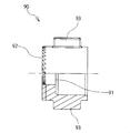
- the slider 90 As shown in FIGS. 1 and 9, the slider 90 is positioned in the axial direction of the inner cylinder 80, is supported by the fixed cylinder 40 in a direction contacting and separating from the inner cylinder 80, and is non-rotatably supported by the fixed cylinder 40. It is what is done.
- the slider 90 is formed in a donut shape having a center hole 91, and is integrally formed of a rigid synthetic resin such as POM (polyacetal).
- the slider 90 includes the following units. Each part of the slider 90 is not limited to the following (1) to (3).
- (1) Center hole 91 The central hole 91 penetrates horizontally in a circular shape, and the slider 90 is formed in a donut shape centering on the central hole 91.
- a shaft portion 82 of the inner cylinder 80 is passed through the center hole 91, and the shaft portion 82 projects from the center hole 91.
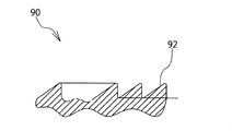
- Second tooth portion 92 The second tooth portion 92 faces the first tooth portion 84 of the inner cylinder 80, is located on the annular end surface side centering on the center hole 91, and is formed along the circumferential direction of the annular end surface. ing. The second tooth portion 92 meshes with the first tooth portion 84 of the inner cylinder 80.
- (3) Key projection 93 The key protrusion 93 protrudes from the outer periphery of the slider 90 and fits into the key groove 123 of the fixed cylinder 40.
- the key protrusions 93 are formed in a convex shape in cross section, and a pair is formed in the diameter direction of the slider 90. (Spring 100)
- the spring 100 urges the slider 90 in a direction approaching the inner cylinder 80 as shown in FIGS. 1 and 9.
- the spring 100 is composed of a metal compression spring, is passed through the shaft portion 82 of the inner cylinder 80 protruding from the center hole 91 of the slider 90, and is compressed between the cap 110 described later.
- the metal compression spring was illustrated as the spring 100, it is not limited to this, For example, you may utilize what is called a resin spring using the elasticity of a synthetic resin.
- Cap 110 As shown in FIGS. 1, 4 to 6, 8, and 9, the cap 110 is attached to the opening 121 of the outer cylinder 120 and closes the opening 121.
- the cap 110 is integrally formed of a thermoplastic synthetic resin such as POM (polyacetal) having appropriate elasticity and rigidity.
- the cap 110 includes the following parts as shown in FIGS. Each part of the cap 110 is not limited to the following (1) to (4).
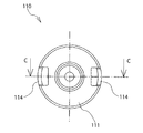
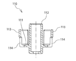
- (1) Annular bottom 111 The annular bottom portion 111 is formed in an annular shape around a guide cylinder 112 described later, and closes the opening 121 of the outer cylinder 120 and abuts against one end portion of the spring 100 to compress the spring 100.
- the guide cylinder 112 protrudes in a cylindrical shape from the center of the annular bottom portion 111 toward the inside of the outer cylinder 120.
- the guide tube 112 is inserted into the shaft portion 82 of the inner tube 80 protruding from the center hole 91 of the slider 90.
- the shaft portion 82 abuts against the annular bottom of the guide tube 112.
- a spring 100 is passed through the outer periphery of the guide tube 112. One end of the spring 100 contacts the end surface of the slider 90 on the side without the second tooth portion 92, and the other end contacts the annular bottom 111 of the cap 110. Compressed between the two.
- the attachment piece 113 extends from the outer periphery of the annular bottom portion 111 in the same direction as the guide tube 112 and fits on the outer periphery of the opening 121 of the outer tube 120.
- a pair of attachment pieces 113 are formed in the diameter direction of the annular bottom portion 111.
- Locking hole 114 The locking holes 114 are formed in the pair of attachment pieces 113, respectively, and are fitted into the pair of claw portions 124 of the outer cylinder 120 using the elasticity of the attachment pieces 113, respectively.
- the locking hole 114 is formed in the cap 110 and the claw portion 124 is formed in the outer cylinder 120
- the invention is not limited to this, but although not shown, a claw portion is formed on the cap 110 side and the outer cylinder 120 side is formed. A locking hole may be formed. (Operation of hinge device 10) The operation of the assembled hinge device 10 having the above-described configuration will be described below.
- the support leg 130 of the fixed cylinder 40 is fixed to the base 20 side, and the shaft tip 52 of the shaft 50 protruding from the fixed cylinder 40 is connected to the opening / closing body 30.
- Opening and closing body 30 opening operation As shown in FIG. 2, when the open / close body 30 in the closed state is opened, the first and second tooth portions 84 and 92 slide over so that the connection state between the inner cylinder 80 and the slider 90 is achieved.
- the inner cylinder 80 idles in the outer cylinder 120 as the shaft 50 rotates and the shaft 50 rotates.
- the opening / closing body 30 can be opened easily.
- the opening force of the opening / closing body 30 is released, the first and second tooth portions 84 and 92 are engaged with each other, whereby the inner cylinder 80 and the slider 90 are returned to the connected state, and the friction between the inner cylinder 80 and the shaft 50 is achieved.
- the opening / closing body 30 stops at a position where the opening force is released, as shown by a one-dot chain line in FIG. (Operation to close the opening / closing body 30) As shown by the one-dot chain line in FIG.
- a bracket 200 is attached to the shaft 50 as shown in FIGS.
- the bracket 200 has a bearing portion 210 into which the shaft tip 52 of the shaft 50 can be inserted, and a mounting portion that is bent and extends from the outer periphery of the bearing portion 210 into an L-shaped cross section.
- the bracket 200 is integrally formed of a thermoplastic synthetic resin having rigidity, such as POM (polyacetal).
- the bracket 200 is made of synthetic resin, it is not limited to this and may be made of metal.
- the bearing portion 210 is formed in a shape suitable for the cross-sectional oval shape or the cross-sectional shape of the shaft tip portion 52 of the shaft 50, and the idling of the bearing portion 210 with respect to the shaft 50 is prevented.
- a plurality of, for example, two guide pins 221 protrude from the mounting portion 220.
- the opening / closing body 30 is formed with a recess or a hole into which the guide pin 221 fits.
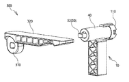
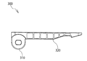
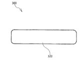
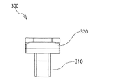
- the arm 300 is attached to the shaft 50 as shown in FIGS. Specifically, as shown in FIGS. 44 to 50, the arm 300 includes a bearing portion 310 into which the shaft tip 52 of the shaft 50 can be inserted, and an insertion portion 320 extending in a tangential direction from the outer periphery of the bearing portion 310. I have.
- the arm 300 is integrally formed of a thermoplastic synthetic resin having rigidity, such as POM (polyacetal).
- the arm 300 is made of synthetic resin, but is not limited to this and may be made of metal.
- the bearing portion 310 is formed in a shape suitable for the cross-sectional oval shape or the D-shape of the shaft tip portion 52 of the shaft 50, and the idling of the bearing portion 310 with respect to the shaft 50 is prevented.
- the insertion part 320 is formed in a tapered shape in which the upper and lower thicknesses gradually decrease toward the tip part.
- the opening / closing body 30 is formed with a groove or a hole into which the insertion portion 320 can be inserted.
- the same components as those in the first embodiment described above with reference to FIGS. 1 to 34 are denoted by the same reference numerals, and the description thereof is omitted.
- the shaft tip 52 of the shaft 50 protruding from the fixed cylinder 40 is inserted into the bearing portion 310 of the arm 300.
- the insertion portion 320 is inserted into a groove or a hole of the opening / closing body 30, so that the shaft 50 can be easily and quickly attached to the opening / closing body 30.
Landscapes
- Physics & Mathematics (AREA)
- General Physics & Mathematics (AREA)
- Engineering & Computer Science (AREA)
- Mechanical Engineering (AREA)
- Pivots And Pivotal Connections (AREA)
Abstract
ヒンジ装置は、固定筒、シャフト、シャフトが固定筒内を回転する際に摩擦抵抗によるトルクを発生させ、開閉体の最大開放位置から下方に向かって所定角度、閉じた回転角度範囲においては、開閉体を自由な位置に無段階で静止可能として、回転角度範囲を超えて閉じた際に、開閉体の自重により閉じる力がトルクを超えるように設定し、開閉体がゆっくりと閉じるトルク発生機構を備える。
Description
この発明は、例えばプリンタや複写機等のベースに対して、上方に向かって開く原稿圧着板、原稿自動送装置(ADF)或いはスキャナ等の開閉体を開閉可能に支持するヒンジ装置であって、開閉体を開いた際に、自由な位置に無段階で静止できるとともに、閉じる際に開閉体の自重による急激な落下を防止することができるようにしたものである。
従来、圧縮コイルバネによる開方向のモーメントを開閉体に作用させ、当該開方向のモーメントの大きさと、開閉体の自重によって生ずる閉方向のモーメントの大きさとを均衡させることで、開閉体を全開状態に保持するようにしたヒンジ装置が知られている(特許文献1の段落番号「0016」~「0019」、図2、図4及び図5参照)。
なお、オイル等の粘性流体を使用した回転ダンパーであるが、ラチェット機構を組み込んだものも知られている(特許文献2の段落番号「0017」~「0019」及び図1~3)
なお、オイル等の粘性流体を使用した回転ダンパーであるが、ラチェット機構を組み込んだものも知られている(特許文献2の段落番号「0017」~「0019」及び図1~3)
しかし、上記した従来のヒンジ装置は、圧縮コイルバネによる開方向のモーメントの大きさと、開閉体の自重によって生ずる閉方向のモーメントの大きさとを均衡させる均衡点の位置の設定が設計上、困難であり、圧縮コイルバネの部品精度により、均衡点の位置がバラ付き易く、又、圧縮コイルバネの疲労により均衡点が変化し易いという問題点があった。
また、上記した従来のヒンジ装置は、開閉体の重量により、圧縮コイルバネのバネ力が左右され、開閉体の重量が増加すると、装置が大型化してしまうという問題点があった。
そこで、本発明は、上記した従来の技術の有する問題点に鑑みてなされたものであり、その目的とするところは、開閉体を開いた際に、自由な位置に無段階で静止できるとともに、閉じる際に開閉体の自重による急激な落下を防止することができるようにしたものである。
そこで、本発明は、上記した従来の技術の有する問題点に鑑みてなされたものであり、その目的とするところは、開閉体を開いた際に、自由な位置に無段階で静止できるとともに、閉じる際に開閉体の自重による急激な落下を防止することができるようにしたものである。
本発明は、上記した目的を達成するためになされたものであり、本発明は、次の点を特徴とする。
第1に、ベースに対して上方に向かって開く開閉体を開閉可能に支持するヒンジ装置である。
第2に、ヒンジ装置は、次の構成を備える。
(1)固定筒
固定筒は、ベースに固定されるものである。
第2に、ヒンジ装置は、次の構成を備える。
(1)固定筒
固定筒は、ベースに固定されるものである。
(2)シャフト
シャフトは、固定筒内に回転可能に支持され、開閉体と一体的に回転するものである。
(3)トルク発生機構
トルク発生機構は、固定筒とシャフトとの間に位置し、シャフトが固定筒内を回転する際に摩擦抵抗によるトルクを発生させ、開閉体の最大開放位置から下方に向かって所定角度、閉じた回転角度範囲においては、開閉体を自由な位置に無段階で静止可能とするものである。
シャフトは、固定筒内に回転可能に支持され、開閉体と一体的に回転するものである。
(3)トルク発生機構
トルク発生機構は、固定筒とシャフトとの間に位置し、シャフトが固定筒内を回転する際に摩擦抵抗によるトルクを発生させ、開閉体の最大開放位置から下方に向かって所定角度、閉じた回転角度範囲においては、開閉体を自由な位置に無段階で静止可能とするものである。
これに加え、トルク発生機構は、回転角度範囲を超えて閉じた際に、開閉体の自重により閉じる力がトルクを超えるように設定し、開閉体がゆっくりと閉じるものである。
本発明は、次の点を特徴として備えていてもよい。
本発明は、次の点を特徴として備えていてもよい。
すなわち、ヒンジ装置は、次の構成を備える。
(1)クラッチ機構
クラッチ機構は、トルク発生機構とシャフトとの間に位置し、開閉体を開く際に、トルク発生機構からシャフトへのトルクの伝達を遮断するものである。
この場合、クラッチ機構により、開閉体を開く際のトルク発生機構によるトルクの伝達を遮断することで、開閉体を比較的軽快に開放することができる。
本発明は、次の点を特徴として備えていてもよい。
(1)クラッチ機構
クラッチ機構は、トルク発生機構とシャフトとの間に位置し、開閉体を開く際に、トルク発生機構からシャフトへのトルクの伝達を遮断するものである。
この場合、クラッチ機構により、開閉体を開く際のトルク発生機構によるトルクの伝達を遮断することで、開閉体を比較的軽快に開放することができる。
本発明は、次の点を特徴として備えていてもよい。
すなわち、クラッチ機構は、ラチェット機構(例えば歯部)を用いている。
この場合、ラチェット機構を用いて、開閉体を開く際に、トルクの伝達を遮断することができる。
本発明は、次の点を特徴として備えていてもよい。
この場合、ラチェット機構を用いて、開閉体を開く際に、トルクの伝達を遮断することができる。
本発明は、次の点を特徴として備えていてもよい。
すなわち、クラッチ機構は、次の構成を備える。
(1)内筒
内筒は、固定筒とシャフトとの間に位置し、固定筒に対して回転可能に支持されるとともに、シャフトが摩擦抵抗を伴って回転可能に挿入されるものである。
(1)内筒
内筒は、固定筒とシャフトとの間に位置し、固定筒に対して回転可能に支持されるとともに、シャフトが摩擦抵抗を伴って回転可能に挿入されるものである。
(2)スライダ
スライダは、内筒の軸線方向に位置し、内筒と接離する方向に固定筒に支持されるとともに、固定筒に回転不能に支持されるものである。
(3)バネ
バネは、スライダを内筒に向かって接近する方向に付勢するものである。
スライダは、内筒の軸線方向に位置し、内筒と接離する方向に固定筒に支持されるとともに、固定筒に回転不能に支持されるものである。
(3)バネ
バネは、スライダを内筒に向かって接近する方向に付勢するものである。
(4)一対の歯部
一対の歯部は、内筒とスライダとの接触面にそれぞれ形成され、開閉体を閉じる際に、内筒の回転を阻止するものである。
これに加え、一対の歯部は、開閉体を開く際に、バネの付勢力に抗して、スライダを離隔させ、内筒の回転を許容する、互いに噛み合うものである。
この場合、内筒、スライダ、バネの3個の部品からクラッチ機構を構成することができる。
本発明は、次の点を特徴とする。
一対の歯部は、内筒とスライダとの接触面にそれぞれ形成され、開閉体を閉じる際に、内筒の回転を阻止するものである。
これに加え、一対の歯部は、開閉体を開く際に、バネの付勢力に抗して、スライダを離隔させ、内筒の回転を許容する、互いに噛み合うものである。
この場合、内筒、スライダ、バネの3個の部品からクラッチ機構を構成することができる。
本発明は、次の点を特徴とする。
第1に、シャフトを金属製とする。
第2に、内筒を、合成樹脂により一体的に成形している。
この場合、金属と合成樹脂との摩擦抵抗を利用することができる。
第2に、内筒を、合成樹脂により一体的に成形している。
この場合、金属と合成樹脂との摩擦抵抗を利用することができる。
本発明は、以上のように構成されているので、開閉体を開いた際に、自由な位置に無段階で静止できるとともに、閉じる際に開閉体の自重による急激な落下を防止することができる。
すなわち、上記した従来のヒンジ装置と比較し、圧縮コイルバネによる開方向のモーメントを開閉体に作用させる必要が無く、シャフトと固定筒との間の摩擦抵抗を利用しているので、設計上の自由度が高く、又、装置の小型化にも有利である。
(第1の実施の形態)
図1~34を用いて、本発明の第1の実施の形態について説明する。
(ヒンジ装置10)
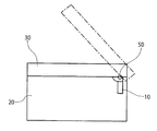
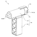
図1~4中、10は、ヒンジ装置であって、ヒンジ装置10は、図2及び図3に示すように、ベース20に対して上方に向かって開く開閉体30を開閉可能に支持するものである。
ベース20は、例えばプリンタや複写機等から構成する。なお、ベース20として、プリンタや複写機を例示したが、これらに限定されず、スキャナ、プリンタ、複写機、スキャナのうち、複数の機能を備えた複合機であっても良い。
図1~34を用いて、本発明の第1の実施の形態について説明する。
(ヒンジ装置10)
図1~4中、10は、ヒンジ装置であって、ヒンジ装置10は、図2及び図3に示すように、ベース20に対して上方に向かって開く開閉体30を開閉可能に支持するものである。
ベース20は、例えばプリンタや複写機等から構成する。なお、ベース20として、プリンタや複写機を例示したが、これらに限定されず、スキャナ、プリンタ、複写機、スキャナのうち、複数の機能を備えた複合機であっても良い。
開閉体30は、原稿圧着板、原稿自動送装置(ADF)或いはスキャナ等から構成する。なお、開閉体30として、原稿圧着板、原稿自動送装置(ADF)、スキャナを例示したが、これらに限定されず、原稿圧着板、原稿自動送装置(ADF)、スキャナのうち、複数の機能を備えた複合体であっても良い。
具体的には、ヒンジ装置10は、図1に示すように、大別すると、次のパーツを備える。
具体的には、ヒンジ装置10は、図1に示すように、大別すると、次のパーツを備える。
なお、次の(1)~(4)については、後述する。
(1)固定筒40
(2)シャフト50
(3)トルク発生機構60
(4)クラッチ機構70
なお、ヒンジ装置10のパーツは、上記した(1)~(4)に限定されない。
(固定筒40)
固定筒40は、ベース20に固定されるものである。固定筒40は、剛性を有する、例えばPOM(ポリアセタール)等の熱可塑性の合成樹脂により一体的に成形されている。
(1)固定筒40
(2)シャフト50
(3)トルク発生機構60
(4)クラッチ機構70
なお、ヒンジ装置10のパーツは、上記した(1)~(4)に限定されない。
(固定筒40)
固定筒40は、ベース20に固定されるものである。固定筒40は、剛性を有する、例えばPOM(ポリアセタール)等の熱可塑性の合成樹脂により一体的に成形されている。
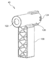
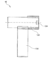
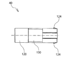
具体的には、固定筒40は、図10~16に示すように、次の各部を備える。
なお、次の(1)及び(2)については、後述する。
(1)外筒120
(2)支持脚130
なお、固定筒40の各部は、上記した(1)及び(2)に限定されない。
(シャフト50)
シャフト50は、固定筒40内に回転可能に支持され、開閉体30と一体的に回転するものである。シャフト50は、例えば金属製である。なお、シャフト50として、金属製を例示したが、これに限定されず、例えば合成樹脂製としても良い。
なお、次の(1)及び(2)については、後述する。
(1)外筒120
(2)支持脚130
なお、固定筒40の各部は、上記した(1)及び(2)に限定されない。
(シャフト50)
シャフト50は、固定筒40内に回転可能に支持され、開閉体30と一体的に回転するものである。シャフト50は、例えば金属製である。なお、シャフト50として、金属製を例示したが、これに限定されず、例えば合成樹脂製としても良い。
具体的には、シャフト50は、図22に示すように、次の各部を備える。
なお、シャフト50の各部は、次の(1)及び(2)に限定されない。
(1)基部51
基部51は、図22に示すように、シャフト50の一端部に位置し、断面が円形に形成され、後述する内筒80内に圧入される。
なお、シャフト50の各部は、次の(1)及び(2)に限定されない。
(1)基部51
基部51は、図22に示すように、シャフト50の一端部に位置し、断面が円形に形成され、後述する内筒80内に圧入される。
(2)軸先端部52
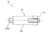
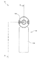
軸先端部52は、図22に示すように、シャフト50の他端部に位置し、断面が非円形、例えば断面小判形或いは断面D形に形成されている。軸先端部52は、シャフト50を固定筒40内に挿入した状態において、図4~7及び図9に示すように、固定筒40から外部に突出し、開閉体30に連結され、図2及び図3に示すように、開閉体30と一体的に回転する。
軸先端部52は、図22に示すように、シャフト50の他端部に位置し、断面が非円形、例えば断面小判形或いは断面D形に形成されている。軸先端部52は、シャフト50を固定筒40内に挿入した状態において、図4~7及び図9に示すように、固定筒40から外部に突出し、開閉体30に連結され、図2及び図3に示すように、開閉体30と一体的に回転する。
なお、軸先端部52の断面形状として、小判形或いはD形を例示したが、これらに限定されず、非円形であれば良い。また、シャフト50と開閉体30との連結は、例えばローレット形状やビス止め形状等を採用しても良い。
(トルク発生機構60)
トルク発生機構60は、図1に示すように、固定筒40とシャフト50との間に位置し、シャフト50が固定筒40内を回転する際に摩擦抵抗によるトルクを発生させ、開閉体30の最大開放位置(最大開放角度、例えば45度)から下方に向かって所定角度(例えば40度)、閉じた第1の回転角度範囲(例えば開放角度5~45度)においては、開閉体30を自由な位置に無段階で静止可能として、第1の回転角度範囲(例えば開放角度5~45度)を超えて閉じた際に、開閉体30の自重により閉じる力がトルクを超えるように設定し、開閉体30がゆっくりと閉じるものである。
(トルク発生機構60)
トルク発生機構60は、図1に示すように、固定筒40とシャフト50との間に位置し、シャフト50が固定筒40内を回転する際に摩擦抵抗によるトルクを発生させ、開閉体30の最大開放位置(最大開放角度、例えば45度)から下方に向かって所定角度(例えば40度)、閉じた第1の回転角度範囲(例えば開放角度5~45度)においては、開閉体30を自由な位置に無段階で静止可能として、第1の回転角度範囲(例えば開放角度5~45度)を超えて閉じた際に、開閉体30の自重により閉じる力がトルクを超えるように設定し、開閉体30がゆっくりと閉じるものである。
すなわち、第1の回転角度範囲(例えば開放角度5~45度)においては、トルク発生機構60がいわゆるフリーストップ機構として機能し、残る第2の回転角度範囲(例えば開放角度0~4度)においては、いわゆるダンパーとして機能する。
なお、最大開放角度として、「45度」を、所定角度として「40度」を、第1の回転角度範囲として「5~45度」を、第2の回転角度範囲として「0~4度」をそれぞれ例示したが、これらの数値に限定されない。
なお、最大開放角度として、「45度」を、所定角度として「40度」を、第1の回転角度範囲として「5~45度」を、第2の回転角度範囲として「0~4度」をそれぞれ例示したが、これらの数値に限定されない。
具体的には、トルク発生機構60は、図1に示すように、シャフト50に加え、次のパーツから構成されている。
なお、次の(1)については、後述する。
(1)内筒80
なお、トルク発生機構60のパーツは、上記した(1)に限定されない。
(クラッチ機構70)
クラッチ機構70は、図1に示すように、トルク発生機構60とシャフト50との間に位置し、開閉体30を開く際に、トルク発生機構60からシャフト50へのトルクの伝達を遮断するものである。
なお、次の(1)については、後述する。
(1)内筒80
なお、トルク発生機構60のパーツは、上記した(1)に限定されない。
(クラッチ機構70)
クラッチ機構70は、図1に示すように、トルク発生機構60とシャフト50との間に位置し、開閉体30を開く際に、トルク発生機構60からシャフト50へのトルクの伝達を遮断するものである。
クラッチ機構70は、例えばラチェット機構を用いている。
具体的には、クラッチ機構70は、図1に示すように、内筒80に加え、次のパーツから構成されている。
なお、次の(1)~(3)については、後述する。
(1)スライダ90
(2)バネ100
(3)キャップ110
なお、クラッチ機構70のパーツは、上記した(1)~(3)に限定されない。
(外筒120)
外筒120は、図1及び図9に示すように、中空な円筒形に形成され、シャフト50、並びに後述する内筒80、スライダ90、バネ100、キャップ110が装着される。
具体的には、クラッチ機構70は、図1に示すように、内筒80に加え、次のパーツから構成されている。
なお、次の(1)~(3)については、後述する。
(1)スライダ90
(2)バネ100
(3)キャップ110
なお、クラッチ機構70のパーツは、上記した(1)~(3)に限定されない。
(外筒120)
外筒120は、図1及び図9に示すように、中空な円筒形に形成され、シャフト50、並びに後述する内筒80、スライダ90、バネ100、キャップ110が装着される。
具体的には、外筒120は、図10~16に示すように、次の各部を備える。
なお、外筒120の各部は、次の(1)~(4)に限定されない。
(1)開口部121
開口部121は、外筒120の一端部に位置し、後述するキャップ110により閉じられる。
(2)貫通孔122
貫通孔122は、外筒120の一端部に位置し、開口部121より一回り小さい円形に形成されている。貫通孔122には、外筒120内に挿入されたシャフト50の軸先端部52が通り、当該軸先端部52は、貫通孔122を通して外側に突出する。
なお、外筒120の各部は、次の(1)~(4)に限定されない。
(1)開口部121
開口部121は、外筒120の一端部に位置し、後述するキャップ110により閉じられる。
(2)貫通孔122
貫通孔122は、外筒120の一端部に位置し、開口部121より一回り小さい円形に形成されている。貫通孔122には、外筒120内に挿入されたシャフト50の軸先端部52が通り、当該軸先端部52は、貫通孔122を通して外側に突出する。
(3)キー溝123
キー溝123は、外筒120の開口部121側に位置し、後述するスライダ90のキー突起93がはまり込む。キー溝123は、断面凹形に形成され、外筒120の内周面、並びに開口部121に向かって開放し、後述する支持脚130の突出方向に平行に、上下に一対形成されている。キー溝123の全長は、キー突起93の全長より長く設定され、キー突起93はキー溝123に沿ってスライドすることで、スライダ90は外筒120の軸線方向にスライドする。また、スライダ90のキー突起93が、キー溝123にはまる込むことで、外筒120内でのスライダ90の回転が阻止される。
キー溝123は、外筒120の開口部121側に位置し、後述するスライダ90のキー突起93がはまり込む。キー溝123は、断面凹形に形成され、外筒120の内周面、並びに開口部121に向かって開放し、後述する支持脚130の突出方向に平行に、上下に一対形成されている。キー溝123の全長は、キー突起93の全長より長く設定され、キー突起93はキー溝123に沿ってスライドすることで、スライダ90は外筒120の軸線方向にスライドする。また、スライダ90のキー突起93が、キー溝123にはまる込むことで、外筒120内でのスライダ90の回転が阻止される。
(4)爪部124
爪部124は、外筒120の開口部121側の外周面から突出し、後述するキャップ110を係止するためのものである。爪部124は、キー溝123と直交する向きに、左右一対形成されている。
(支持脚130)
支持脚130は、図10、図11及び図13~16に示すように、外筒120から垂下し、ベース20に固定される。支持脚130は、外筒120の全長のほぼ中央から下方に向かって角柱形に延びている。
なお、固定筒40を、支持脚130を介してベース20に固定したが、これに限定されず、固定筒40を例えばネジ止めしても良い。
(内筒80)
内筒80は、図1及び図9に示すように、固定筒40とシャフト50との間に位置し、固定筒40に対して回転可能に支持されるとともに、シャフト50が摩擦抵抗を伴って回転可能に挿入されるものである。内筒80は、剛性を有する、例えばPOM(ポリアセタール)等の熱可塑性の合成樹脂により一体的に成形されている。
爪部124は、外筒120の開口部121側の外周面から突出し、後述するキャップ110を係止するためのものである。爪部124は、キー溝123と直交する向きに、左右一対形成されている。
(支持脚130)
支持脚130は、図10、図11及び図13~16に示すように、外筒120から垂下し、ベース20に固定される。支持脚130は、外筒120の全長のほぼ中央から下方に向かって角柱形に延びている。
なお、固定筒40を、支持脚130を介してベース20に固定したが、これに限定されず、固定筒40を例えばネジ止めしても良い。
(内筒80)
内筒80は、図1及び図9に示すように、固定筒40とシャフト50との間に位置し、固定筒40に対して回転可能に支持されるとともに、シャフト50が摩擦抵抗を伴って回転可能に挿入されるものである。内筒80は、剛性を有する、例えばPOM(ポリアセタール)等の熱可塑性の合成樹脂により一体的に成形されている。
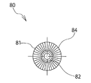
具体的には、内筒80は、図17~21に示すように、次の各部を備える。
なお、内筒80の各部は、次の(1)~(4)に限定されない。
(1)筒本体81
筒本体81は、内筒80の一端部に位置し、円筒形に形成され、シャフト50の基部51が挿入される。
なお、内筒80の各部は、次の(1)~(4)に限定されない。
(1)筒本体81
筒本体81は、内筒80の一端部に位置し、円筒形に形成され、シャフト50の基部51が挿入される。
(2)軸部82
軸部82は、内筒80の一端部に位置し、内筒80の軸線方向に円柱形に細く延びる。軸部82には、後述するスライダ90が挿入され、スライダ90を通してキャップ110に向かって更に突出し、キャップ110との間には、同じく後述するバネ100が通される。
(3)開口部83
開口部83は、筒本体81の端面に位置し、シャフト50の基部51が挿入される。開口部83からは軸先端部52が突出する。
軸部82は、内筒80の一端部に位置し、内筒80の軸線方向に円柱形に細く延びる。軸部82には、後述するスライダ90が挿入され、スライダ90を通してキャップ110に向かって更に突出し、キャップ110との間には、同じく後述するバネ100が通される。
(3)開口部83
開口部83は、筒本体81の端面に位置し、シャフト50の基部51が挿入される。開口部83からは軸先端部52が突出する。
(4)第1の歯部84
第1の歯部84は、軸部82が突出する筒本体81の環状の端面側に位置し、当該環状の端面の円周方向に沿って形成されている。第1の歯部84は、後述するスライダ90の第2の歯部92と噛み合うものである。第1の歯部84と、第2の歯部92とは、開閉体30を閉じる際に、互いに噛み合うことで、スライダ90と内筒80とを連結することで、内筒80の回転を阻止する。これに対し、開閉体30を開く際に、第1の歯部84と第2の歯部92とが乗り越えるようにして滑る。このため、内筒80からスライダ90が離隔し、両者の連結状態が外れ、内筒80の回転が可能となる。
(スライダ90)
スライダ90は、図1及び図9に示すように、内筒80の軸線方向に位置し、内筒80と接離する方向に固定筒40に支持されるとともに、固定筒40に回転不能に支持されるものである。スライダ90は、中心穴91を有するドーナツ形に形成され、剛性を有する、例えばPOM(ポリアセタール)等の熱可塑性の合成樹脂により一体的に成形されている。
第1の歯部84は、軸部82が突出する筒本体81の環状の端面側に位置し、当該環状の端面の円周方向に沿って形成されている。第1の歯部84は、後述するスライダ90の第2の歯部92と噛み合うものである。第1の歯部84と、第2の歯部92とは、開閉体30を閉じる際に、互いに噛み合うことで、スライダ90と内筒80とを連結することで、内筒80の回転を阻止する。これに対し、開閉体30を開く際に、第1の歯部84と第2の歯部92とが乗り越えるようにして滑る。このため、内筒80からスライダ90が離隔し、両者の連結状態が外れ、内筒80の回転が可能となる。
(スライダ90)
スライダ90は、図1及び図9に示すように、内筒80の軸線方向に位置し、内筒80と接離する方向に固定筒40に支持されるとともに、固定筒40に回転不能に支持されるものである。スライダ90は、中心穴91を有するドーナツ形に形成され、剛性を有する、例えばPOM(ポリアセタール)等の熱可塑性の合成樹脂により一体的に成形されている。
具体的には、スライダ90は、図23~28に示すように、次の各部を備える。
なお、スライダ90の各部は、次の(1)~(3)に限定されない。
(1)中心穴91
中心穴91は、横に円形に貫通するものであり、スライダ90は中心穴91を中心にドーナツ形に形成されている。中心穴91には、内筒80の軸部82が通され、当該軸部82は中心穴91から突出する。
なお、スライダ90の各部は、次の(1)~(3)に限定されない。
(1)中心穴91
中心穴91は、横に円形に貫通するものであり、スライダ90は中心穴91を中心にドーナツ形に形成されている。中心穴91には、内筒80の軸部82が通され、当該軸部82は中心穴91から突出する。
(2)第2の歯部92
第2の歯部92は、内筒80の第1の歯部84と対向し、中心穴91を中心とする環状の端面側に位置し、当該環状の端面の円周方向に沿って形成されている。第2の歯部92は、内筒80の第1の歯部84と噛み合うものである。
(3)キー突起93
キー突起93は、スライダ90の外周から突出し、固定筒40のキー溝123にはまり込むものである。キー突起93は、断面凸形に形成され、スライダ90の直径方向に一対形成されている。
(バネ100)
バネ100は、図1及び図9に示すように、スライダ90を内筒80に向かって接近する方向に付勢するものである。
第2の歯部92は、内筒80の第1の歯部84と対向し、中心穴91を中心とする環状の端面側に位置し、当該環状の端面の円周方向に沿って形成されている。第2の歯部92は、内筒80の第1の歯部84と噛み合うものである。
(3)キー突起93
キー突起93は、スライダ90の外周から突出し、固定筒40のキー溝123にはまり込むものである。キー突起93は、断面凸形に形成され、スライダ90の直径方向に一対形成されている。
(バネ100)
バネ100は、図1及び図9に示すように、スライダ90を内筒80に向かって接近する方向に付勢するものである。
バネ100は、金属製の圧縮スプリングから構成され、スライダ90の中心穴91から突出する内筒80の軸部82に通され、後述するキャップ110との間で圧縮される。
なお、バネ100として、金属製の圧縮スプリングを例示したが、これに限定されず、例えば合成樹脂の弾性を利用したいわゆる樹脂バネを利用して良い。
(キャップ110)
キャップ110は、図1、図4~6、図8及び図9に示すように、外筒120の開口部121に装着され、当該開口部121を閉じるためのものである。キャップ110は、適度な弾性と剛性とを有する、例えばPOM(ポリアセタール)等の熱可塑性の合成樹脂により一体的に成形されている。
なお、バネ100として、金属製の圧縮スプリングを例示したが、これに限定されず、例えば合成樹脂の弾性を利用したいわゆる樹脂バネを利用して良い。
(キャップ110)
キャップ110は、図1、図4~6、図8及び図9に示すように、外筒120の開口部121に装着され、当該開口部121を閉じるためのものである。キャップ110は、適度な弾性と剛性とを有する、例えばPOM(ポリアセタール)等の熱可塑性の合成樹脂により一体的に成形されている。
具体的には、キャップ110は、図29~34に示すように、次の各部を備える。
なお、キャップ110の各部は、次の(1)~(4)に限定されない。
(1)環状底部111
環状底部111は、後述するガイド筒112を中心に環状に形成され、外筒120の開口部121を閉じるとともに、バネ100の一端部に当接し、バネ100を圧縮するためのものである。
なお、キャップ110の各部は、次の(1)~(4)に限定されない。
(1)環状底部111
環状底部111は、後述するガイド筒112を中心に環状に形成され、外筒120の開口部121を閉じるとともに、バネ100の一端部に当接し、バネ100を圧縮するためのものである。
(2)ガイド筒112
ガイド筒112は、環状底部111の中心から外筒120の内部に向かって円筒形に突出する。ガイド筒112内には、スライダ90の中心穴91から突出する内筒80の軸部82に挿入される。軸部82は、ガイド筒112の環状の底に突き当たる。
ガイド筒112の外周には、バネ100が通され、バネ100の一端部は、第2の歯部92の無い側のスライダ90の端面に、他端部はキャップ110の環状底部111にそれぞれ当接し、両者の間で圧縮される。
ガイド筒112は、環状底部111の中心から外筒120の内部に向かって円筒形に突出する。ガイド筒112内には、スライダ90の中心穴91から突出する内筒80の軸部82に挿入される。軸部82は、ガイド筒112の環状の底に突き当たる。
ガイド筒112の外周には、バネ100が通され、バネ100の一端部は、第2の歯部92の無い側のスライダ90の端面に、他端部はキャップ110の環状底部111にそれぞれ当接し、両者の間で圧縮される。
(3)取付片113
取付片113は、環状底部111の外周から、ガイド筒112と同方向に延び、外筒120の開口部121の外周にはまり合う。取付片113は、環状底部111の直径方向に一対形成されている。
(4)係止孔114
係止孔114は、一対の取付片113にそれぞれ形成され、外筒120の一対の爪部124にそれぞれ、取付片113の弾性を利用してはまり込むものである。
取付片113は、環状底部111の外周から、ガイド筒112と同方向に延び、外筒120の開口部121の外周にはまり合う。取付片113は、環状底部111の直径方向に一対形成されている。
(4)係止孔114
係止孔114は、一対の取付片113にそれぞれ形成され、外筒120の一対の爪部124にそれぞれ、取付片113の弾性を利用してはまり込むものである。
なお、キャップ110に係止孔114を形成し、外筒120に爪部124を形成したが、これらに限定されず、図示しないが、キャップ110側に爪部を形成し、外筒120側に係止孔を形成しても良い。
(ヒンジ装置10の動作)
上記した構成を有する組み立て状態のヒンジ装置10の動作について、以下に説明する。
(ヒンジ装置10の動作)
上記した構成を有する組み立て状態のヒンジ装置10の動作について、以下に説明する。
まず、固定筒40の支持脚130を、ベース20側に固定し、固定筒40から突出するシャフト50の軸先端部52を開閉体30に連結する。
(開閉体30の開く動作)
図2に示すように、閉じた状態の開閉体30を開くと、第1、第2の歯部84,92とが乗り越えるようにして滑ることで、内筒80とスライダ90との連結状態が外れ、シャフト50の回転に伴って、内筒80が外筒120内で空転する。
(開閉体30の開く動作)
図2に示すように、閉じた状態の開閉体30を開くと、第1、第2の歯部84,92とが乗り越えるようにして滑ることで、内筒80とスライダ90との連結状態が外れ、シャフト50の回転に伴って、内筒80が外筒120内で空転する。
このため、開閉体30を軽快に開放できる。
開閉体30を開く力を解放すると、第1、第2の歯部84,92とが噛み合うことで、内筒80とスライダ90とが連結状態に復帰し、内筒80とシャフト50との摩擦抵抗によるトルクにより、図2に一点鎖線で示すように、開閉体30が開く力を解放した位置に静止する。
(開閉体30の閉じる動作)
図2に一点鎖線で示すように、開いた開閉体30を閉じると、第1、第2の歯部84,92とが噛み合うことで、内筒80とスライダ90との連結状態を維持され、内筒80とシャフト50との摩擦抵抗によるトルクに抗して、開閉体30を閉じる必要がある。
開閉体30を開く力を解放すると、第1、第2の歯部84,92とが噛み合うことで、内筒80とスライダ90とが連結状態に復帰し、内筒80とシャフト50との摩擦抵抗によるトルクにより、図2に一点鎖線で示すように、開閉体30が開く力を解放した位置に静止する。
(開閉体30の閉じる動作)
図2に一点鎖線で示すように、開いた開閉体30を閉じると、第1、第2の歯部84,92とが噛み合うことで、内筒80とスライダ90との連結状態を維持され、内筒80とシャフト50との摩擦抵抗によるトルクに抗して、開閉体30を閉じる必要がある。
開閉体30を所定角度(例えば開放角度5度)、閉じた位置で閉じる力を解放すると、図3に示すように、開閉体30の自重により閉じる力がトルクを超え、開閉体30がゆっくりと静粛に閉じる。
なお、閉じた状態に、図示しないが、ロック手段によりロックするようにしても良い。
(第2の実施の形態)
つぎに、図35~43を用いて、本発明の第2の実施の形態について説明する。
なお、閉じた状態に、図示しないが、ロック手段によりロックするようにしても良い。
(第2の実施の形態)
つぎに、図35~43を用いて、本発明の第2の実施の形態について説明する。
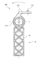
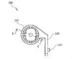
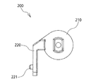
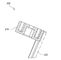
本実施の形態の特徴は、図35及び図43に示すように、シャフト50にブラケット200を装着した点にある。
具体的には、ブラケット200に、図35~43に示すように、シャフト50の軸先端部52が挿入可能な軸受部210と、軸受部210の外周から断面L字形に屈曲して延びる取付部220とを備えている。ブラケット200は、剛性を有する、例えばPOM(ポリアセタール)等の熱可塑性の合成樹脂により一体的に成形されている。
具体的には、ブラケット200に、図35~43に示すように、シャフト50の軸先端部52が挿入可能な軸受部210と、軸受部210の外周から断面L字形に屈曲して延びる取付部220とを備えている。ブラケット200は、剛性を有する、例えばPOM(ポリアセタール)等の熱可塑性の合成樹脂により一体的に成形されている。
なお、ブラケット200を、合成樹脂製としたが、これに限定されず、金属製としても良い。
軸受部210は、図41に示すように、シャフト50の軸先端部52の断面小判形或いは断面D形に適合した形状に形成され、シャフト50に対する軸受部210の空転が阻止される。
取付部220には、図35~図41及び図43に示すように、複数個、例えば2個のガイドピン221を突出する。開閉体30には、図示しないが、ガイドピン221がはまり込む凹部或いは穴を形成しておく。
軸受部210は、図41に示すように、シャフト50の軸先端部52の断面小判形或いは断面D形に適合した形状に形成され、シャフト50に対する軸受部210の空転が阻止される。
取付部220には、図35~図41及び図43に示すように、複数個、例えば2個のガイドピン221を突出する。開閉体30には、図示しないが、ガイドピン221がはまり込む凹部或いは穴を形成しておく。
なお、本実施の形態の説明において、先に図1~34を用いて説明した第1の実施の形態と同一の構成部分については同一の符号を図面に付し、説明を省略する。
ブラケット200の軸受部210には、図35及び図43に示すように、固定筒40から突出するシャフト50の軸先端部52を挿入する。その後、取付部220のガイドピン221を、図示しないが、開閉体30の凹部或いは穴に合わせてはめ込んで位置決めした後、図示しないが、ネジ等により開閉体30に固定する。
(第3の実施の形態)
図43~50を用いて、本発明の第2の実施の形態について説明する。
ブラケット200の軸受部210には、図35及び図43に示すように、固定筒40から突出するシャフト50の軸先端部52を挿入する。その後、取付部220のガイドピン221を、図示しないが、開閉体30の凹部或いは穴に合わせてはめ込んで位置決めした後、図示しないが、ネジ等により開閉体30に固定する。
(第3の実施の形態)
図43~50を用いて、本発明の第2の実施の形態について説明する。
本実施の形態の特徴は、図44及び図45に示すように、シャフト50にアーム300を装着した点にある。
具体的には、アーム300に、図44~50に示すように、シャフト50の軸先端部52が挿入可能な軸受部310と、軸受部310の外周から接線方向に延びる差込部320とを備えている。アーム300は、剛性を有する、例えばPOM(ポリアセタール)等の熱可塑性の合成樹脂により一体的に成形されている。
具体的には、アーム300に、図44~50に示すように、シャフト50の軸先端部52が挿入可能な軸受部310と、軸受部310の外周から接線方向に延びる差込部320とを備えている。アーム300は、剛性を有する、例えばPOM(ポリアセタール)等の熱可塑性の合成樹脂により一体的に成形されている。
なお、アーム300を、合成樹脂製としたが、これに限定されず、金属製としても良い。
軸受部310は、図44~46に示すように、シャフト50の軸先端部52の断面小判形或いは断面D形に適合した形状に形成され、シャフト50に対する軸受部310の空転が阻止される。
差込部320は、図44~46に示すように、先端部に向かって上下の厚みが徐々に減少する先細り状に形成されている。開閉体30には、図示しないが、差込部320を差し込み可能な溝或いは穴を形成しておく。
軸受部310は、図44~46に示すように、シャフト50の軸先端部52の断面小判形或いは断面D形に適合した形状に形成され、シャフト50に対する軸受部310の空転が阻止される。
差込部320は、図44~46に示すように、先端部に向かって上下の厚みが徐々に減少する先細り状に形成されている。開閉体30には、図示しないが、差込部320を差し込み可能な溝或いは穴を形成しておく。
なお、本実施の形態の説明において、先に図1~34を用いて説明した第1の実施の形態と同一の構成部分については同一の符号を図面に付し、説明を省略する。
アーム300の軸受部310には、図44及び図45に示すように、固定筒40から突出するシャフト50の軸先端部52を挿入する。その後、差込部320を、図示しないが、開閉体30の溝或いは穴に差し込むことで、シャフト50を開閉体30に簡便且つ迅速に装着できる。
アーム300の軸受部310には、図44及び図45に示すように、固定筒40から突出するシャフト50の軸先端部52を挿入する。その後、差込部320を、図示しないが、開閉体30の溝或いは穴に差し込むことで、シャフト50を開閉体30に簡便且つ迅速に装着できる。
2010年9月3日に出願された日本特許出願第2010-198045号の明細書、特許請求の範囲、図面及び要約書の全内容をここに引用し、本発明の明細書の開示として、取り入れるものである。
Claims (5)
- ベースに対して上方に向かって開く開閉体を開閉可能に支持するヒンジ装置であって、
前記ヒンジ装置は、
前記ベースに固定される固定筒と、
前記固定筒内に回転可能に支持され、前記開閉体と一体的に回転するシャフトと、
前記固定筒と前記シャフトとの間に位置し、前記シャフトが前記固定筒内を回転する際に摩擦抵抗によるトルクを発生させ、前記開閉体の最大開放位置から下方に向かって所定角度、閉じた回転角度範囲においては、前記開閉体を自由な位置に無段階で静止可能として、前記回転角度範囲を超えて閉じた際に、前記開閉体の自重により閉じる力が前記トルクを超えるように設定し、前記開閉体がゆっくりと閉じるトルク発生機構とを備えていることを特徴とする開閉体用のヒンジ装置。 - 請求項1に記載の開閉体用のヒンジ装置であって、
前記ヒンジ装置は、
前記トルク発生機構と前記シャフトとの間に位置し、前記開閉体を開く際に、前記トルク発生機構から前記シャフトへの前記トルクの伝達を遮断するクラッチ機構を備えていることを特徴とする開閉体用のヒンジ装置。 - 前記ヒンジ装置は、
請求項2に記載の開閉体用のヒンジ装置であって、
前記クラッチ機構は、
ラチェット機構を用いていることを特徴とする開閉体用のヒンジ装置。 - 請求項3に記載の開閉体用のヒンジ装置であって、
前記クラッチ機構は、
前記固定筒と前記シャフトとの間に位置し、前記固定筒に対して回転可能に支持されるとともに、前記シャフトが摩擦抵抗を伴って回転可能に挿入される内筒と、
前記内筒の軸線方向に位置し、前記内筒と接離する方向に前記固定筒に支持されるとともに、前記固定筒に回転不能に支持されるスライダと、
前記スライダを前記内筒に向かって接近する方向に付勢するバネと、
前記内筒と前記スライダとの接触面にそれぞれ形成され、前記開閉体を閉じる際に、前記内筒の回転を阻止し、
前記開閉体を開く際に、前記バネの付勢力に抗して、前記スライダを離隔させ、前記内筒の回転を許容する、互いに噛み合う一対の歯部とを備えていることを特徴とする開閉体用のヒンジ装置。 - 請求項4に記載の開閉体用のヒンジ装置であって、
前記シャフトを金属製とし、
前記内筒を、合成樹脂により一体的に成形していることを特徴とする開閉体用のヒンジ装置。
Applications Claiming Priority (2)
| Application Number | Priority Date | Filing Date | Title |
|---|---|---|---|
| JP2010-198045 | 2010-09-03 | ||
| JP2010198045A JP2012052396A (ja) | 2010-09-03 | 2010-09-03 | 開閉体用のヒンジ装置 |
Publications (1)
| Publication Number | Publication Date |
|---|---|
| WO2012029720A1 true WO2012029720A1 (ja) | 2012-03-08 |
Family
ID=45772806
Family Applications (1)
| Application Number | Title | Priority Date | Filing Date |
|---|---|---|---|
| PCT/JP2011/069480 Ceased WO2012029720A1 (ja) | 2010-09-03 | 2011-08-29 | 開閉体用のヒンジ装置 |
Country Status (3)
| Country | Link |
|---|---|
| JP (1) | JP2012052396A (ja) |
| TW (1) | TW201217625A (ja) |
| WO (1) | WO2012029720A1 (ja) |
Cited By (2)
| Publication number | Priority date | Publication date | Assignee | Title |
|---|---|---|---|---|
| CN112128219A (zh) * | 2020-10-13 | 2020-12-25 | 昆山玮硕恒基智能科技股份有限公司 | 开轻关重转轴 |
| EP4261375A1 (en) * | 2022-04-12 | 2023-10-18 | Saint-Gobain Glass France | Safety hinge for a vertical door |
Families Citing this family (3)
| Publication number | Priority date | Publication date | Assignee | Title |
|---|---|---|---|---|
| JP5912512B2 (ja) * | 2011-12-21 | 2016-04-27 | 吉田プラ工業株式会社 | 化粧料容器 |
| JP6582884B2 (ja) * | 2015-10-30 | 2019-10-02 | ブラザー工業株式会社 | 複合機 |
| JP2018087005A (ja) * | 2017-12-22 | 2018-06-07 | パイオニア株式会社 | 回動部材移動機構 |
Citations (4)
| Publication number | Priority date | Publication date | Assignee | Title |
|---|---|---|---|---|
| JPH0542742U (ja) * | 1991-11-06 | 1993-06-11 | エヌテイエヌ株式会社 | トルク抑制装置 |
| JP2835742B2 (ja) * | 1989-04-18 | 1998-12-14 | 株式会社ニフコ | ヒンジ装置及びこの装置を用いた電子機器 |
| JP2001317537A (ja) * | 2000-05-08 | 2001-11-16 | Sando Kogyosho:Kk | 小型機器用の回転抑制装置 |
| JP2003194044A (ja) * | 2001-12-28 | 2003-07-09 | Ntn Corp | 片側空転チルトヒンジ |
-
2010
- 2010-09-03 JP JP2010198045A patent/JP2012052396A/ja not_active Withdrawn
-
2011
- 2011-08-12 TW TW100128842A patent/TW201217625A/zh unknown
- 2011-08-29 WO PCT/JP2011/069480 patent/WO2012029720A1/ja not_active Ceased
Patent Citations (4)
| Publication number | Priority date | Publication date | Assignee | Title |
|---|---|---|---|---|
| JP2835742B2 (ja) * | 1989-04-18 | 1998-12-14 | 株式会社ニフコ | ヒンジ装置及びこの装置を用いた電子機器 |
| JPH0542742U (ja) * | 1991-11-06 | 1993-06-11 | エヌテイエヌ株式会社 | トルク抑制装置 |
| JP2001317537A (ja) * | 2000-05-08 | 2001-11-16 | Sando Kogyosho:Kk | 小型機器用の回転抑制装置 |
| JP2003194044A (ja) * | 2001-12-28 | 2003-07-09 | Ntn Corp | 片側空転チルトヒンジ |
Cited By (2)
| Publication number | Priority date | Publication date | Assignee | Title |
|---|---|---|---|---|
| CN112128219A (zh) * | 2020-10-13 | 2020-12-25 | 昆山玮硕恒基智能科技股份有限公司 | 开轻关重转轴 |
| EP4261375A1 (en) * | 2022-04-12 | 2023-10-18 | Saint-Gobain Glass France | Safety hinge for a vertical door |
Also Published As
| Publication number | Publication date |
|---|---|
| JP2012052396A (ja) | 2012-03-15 |
| TW201217625A (en) | 2012-05-01 |
Similar Documents
| Publication | Publication Date | Title |
|---|---|---|
| US10754285B2 (en) | Original cover closer and office equipment using the same | |
| WO2012029720A1 (ja) | 開閉体用のヒンジ装置 | |
| JP5382760B2 (ja) | 原稿圧着板開閉装置及び原稿圧着板を備えた事務機器 | |
| JP3733117B2 (ja) | ダンパヒンジ | |
| JP3971276B2 (ja) | ヒンジ装置 | |
| US20110129111A1 (en) | Soft-opening hinge and headphone including same | |
| US20180363349A1 (en) | Opening and closing device for opening and closing body, and various opened and closed bodies having the same | |
| JP2019090258A (ja) | ドアチェック装置 | |
| US10113344B2 (en) | Stay | |
| US8307503B1 (en) | Slow closing hinge apparatus | |
| JP2001098839A (ja) | 開閉体のヒンジ | |
| US20080010777A1 (en) | Hinge damper in opening/closing device | |
| KR102224256B1 (ko) | 힌지장치 | |
| KR101545436B1 (ko) | 프리 스톱 기능을 갖는 도어 힌지 클로저 | |
| US7257862B2 (en) | Decelerating device for insertion between two relatively rotating members, in particular a drum and an oscillating door for loading the drum in a top-loaded washing machine | |
| CN217381271U (zh) | 一种tws无线耳机盒转轴 | |
| CN216895347U (zh) | 一种防强扭转动机构 | |
| JP5474650B2 (ja) | ヒンジ用カバー | |
| JPH09311389A (ja) | 原稿圧着板の開閉装置 | |
| JPH02275108A (ja) | ヒンジ装置及びこの装置を用いた電子機器 | |
| CN207999439U (zh) | 铰接装置及烤炉 | |
| CN212970041U (zh) | 一种耳机充电仓 | |
| TWI447293B (zh) | Damping puller | |
| JP2006138362A (ja) | ヒンジ装置 | |
| JP4691413B2 (ja) | 引戸用クローザ |
Legal Events
| Date | Code | Title | Description |
|---|---|---|---|
| 121 | Ep: the epo has been informed by wipo that ep was designated in this application |
Ref document number: 11821736 Country of ref document: EP Kind code of ref document: A1 |
|
| NENP | Non-entry into the national phase |
Ref country code: DE |
|
| 122 | Ep: pct application non-entry in european phase |
Ref document number: 11821736 Country of ref document: EP Kind code of ref document: A1 |