WO2012029532A1 - Chargeur - Google Patents
Chargeur Download PDFInfo
- Publication number
- WO2012029532A1 WO2012029532A1 PCT/JP2011/068463 JP2011068463W WO2012029532A1 WO 2012029532 A1 WO2012029532 A1 WO 2012029532A1 JP 2011068463 W JP2011068463 W JP 2011068463W WO 2012029532 A1 WO2012029532 A1 WO 2012029532A1
- Authority
- WO
- WIPO (PCT)
- Prior art keywords
- charger
- cord
- storage
- plug
- battery
- Prior art date
Links
Images


Classifications
-
- B—PERFORMING OPERATIONS; TRANSPORTING
- B60—VEHICLES IN GENERAL
- B60L—PROPULSION OF ELECTRICALLY-PROPELLED VEHICLES; SUPPLYING ELECTRIC POWER FOR AUXILIARY EQUIPMENT OF ELECTRICALLY-PROPELLED VEHICLES; ELECTRODYNAMIC BRAKE SYSTEMS FOR VEHICLES IN GENERAL; MAGNETIC SUSPENSION OR LEVITATION FOR VEHICLES; MONITORING OPERATING VARIABLES OF ELECTRICALLY-PROPELLED VEHICLES; ELECTRIC SAFETY DEVICES FOR ELECTRICALLY-PROPELLED VEHICLES
- B60L53/00—Methods of charging batteries, specially adapted for electric vehicles; Charging stations or on-board charging equipment therefor; Exchange of energy storage elements in electric vehicles
- B60L53/10—Methods of charging batteries, specially adapted for electric vehicles; Charging stations or on-board charging equipment therefor; Exchange of energy storage elements in electric vehicles characterised by the energy transfer between the charging station and the vehicle
- B60L53/14—Conductive energy transfer
-
- B—PERFORMING OPERATIONS; TRANSPORTING
- B60—VEHICLES IN GENERAL
- B60L—PROPULSION OF ELECTRICALLY-PROPELLED VEHICLES; SUPPLYING ELECTRIC POWER FOR AUXILIARY EQUIPMENT OF ELECTRICALLY-PROPELLED VEHICLES; ELECTRODYNAMIC BRAKE SYSTEMS FOR VEHICLES IN GENERAL; MAGNETIC SUSPENSION OR LEVITATION FOR VEHICLES; MONITORING OPERATING VARIABLES OF ELECTRICALLY-PROPELLED VEHICLES; ELECTRIC SAFETY DEVICES FOR ELECTRICALLY-PROPELLED VEHICLES
- B60L53/00—Methods of charging batteries, specially adapted for electric vehicles; Charging stations or on-board charging equipment therefor; Exchange of energy storage elements in electric vehicles
- B60L53/20—Methods of charging batteries, specially adapted for electric vehicles; Charging stations or on-board charging equipment therefor; Exchange of energy storage elements in electric vehicles characterised by converters located in the vehicle
- B60L53/22—Constructional details or arrangements of charging converters specially adapted for charging electric vehicles
-
- H—ELECTRICITY
- H02—GENERATION; CONVERSION OR DISTRIBUTION OF ELECTRIC POWER
- H02J—CIRCUIT ARRANGEMENTS OR SYSTEMS FOR SUPPLYING OR DISTRIBUTING ELECTRIC POWER; SYSTEMS FOR STORING ELECTRIC ENERGY
- H02J7/00—Circuit arrangements for charging or depolarising batteries or for supplying loads from batteries
- H02J7/0042—Circuit arrangements for charging or depolarising batteries or for supplying loads from batteries characterised by the mechanical construction
-
- H—ELECTRICITY
- H05—ELECTRIC TECHNIQUES NOT OTHERWISE PROVIDED FOR
- H05K—PRINTED CIRCUITS; CASINGS OR CONSTRUCTIONAL DETAILS OF ELECTRIC APPARATUS; MANUFACTURE OF ASSEMBLAGES OF ELECTRICAL COMPONENTS
- H05K5/00—Casings, cabinets or drawers for electric apparatus
- H05K5/02—Details
-
- H—ELECTRICITY
- H01—ELECTRIC ELEMENTS
- H01M—PROCESSES OR MEANS, e.g. BATTERIES, FOR THE DIRECT CONVERSION OF CHEMICAL ENERGY INTO ELECTRICAL ENERGY
- H01M10/00—Secondary cells; Manufacture thereof
- H01M10/42—Methods or arrangements for servicing or maintenance of secondary cells or secondary half-cells
- H01M10/4207—Methods or arrangements for servicing or maintenance of secondary cells or secondary half-cells for several batteries or cells simultaneously or sequentially
-
- H—ELECTRICITY
- H01—ELECTRIC ELEMENTS
- H01M—PROCESSES OR MEANS, e.g. BATTERIES, FOR THE DIRECT CONVERSION OF CHEMICAL ENERGY INTO ELECTRICAL ENERGY
- H01M10/00—Secondary cells; Manufacture thereof
- H01M10/42—Methods or arrangements for servicing or maintenance of secondary cells or secondary half-cells
- H01M10/46—Accumulators structurally combined with charging apparatus
-
- H—ELECTRICITY
- H01—ELECTRIC ELEMENTS
- H01M—PROCESSES OR MEANS, e.g. BATTERIES, FOR THE DIRECT CONVERSION OF CHEMICAL ENERGY INTO ELECTRICAL ENERGY
- H01M16/00—Structural combinations of different types of electrochemical generators
-
- H—ELECTRICITY
- H01—ELECTRIC ELEMENTS
- H01M—PROCESSES OR MEANS, e.g. BATTERIES, FOR THE DIRECT CONVERSION OF CHEMICAL ENERGY INTO ELECTRICAL ENERGY
- H01M2220/00—Batteries for particular applications
- H01M2220/20—Batteries in motive systems, e.g. vehicle, ship, plane
-
- Y—GENERAL TAGGING OF NEW TECHNOLOGICAL DEVELOPMENTS; GENERAL TAGGING OF CROSS-SECTIONAL TECHNOLOGIES SPANNING OVER SEVERAL SECTIONS OF THE IPC; TECHNICAL SUBJECTS COVERED BY FORMER USPC CROSS-REFERENCE ART COLLECTIONS [XRACs] AND DIGESTS
- Y02—TECHNOLOGIES OR APPLICATIONS FOR MITIGATION OR ADAPTATION AGAINST CLIMATE CHANGE
- Y02E—REDUCTION OF GREENHOUSE GAS [GHG] EMISSIONS, RELATED TO ENERGY GENERATION, TRANSMISSION OR DISTRIBUTION
- Y02E60/00—Enabling technologies; Technologies with a potential or indirect contribution to GHG emissions mitigation
- Y02E60/10—Energy storage using batteries
-
- Y—GENERAL TAGGING OF NEW TECHNOLOGICAL DEVELOPMENTS; GENERAL TAGGING OF CROSS-SECTIONAL TECHNOLOGIES SPANNING OVER SEVERAL SECTIONS OF THE IPC; TECHNICAL SUBJECTS COVERED BY FORMER USPC CROSS-REFERENCE ART COLLECTIONS [XRACs] AND DIGESTS
- Y02—TECHNOLOGIES OR APPLICATIONS FOR MITIGATION OR ADAPTATION AGAINST CLIMATE CHANGE
- Y02T—CLIMATE CHANGE MITIGATION TECHNOLOGIES RELATED TO TRANSPORTATION
- Y02T10/00—Road transport of goods or passengers
- Y02T10/60—Other road transportation technologies with climate change mitigation effect
- Y02T10/70—Energy storage systems for electromobility, e.g. batteries
-
- Y—GENERAL TAGGING OF NEW TECHNOLOGICAL DEVELOPMENTS; GENERAL TAGGING OF CROSS-SECTIONAL TECHNOLOGIES SPANNING OVER SEVERAL SECTIONS OF THE IPC; TECHNICAL SUBJECTS COVERED BY FORMER USPC CROSS-REFERENCE ART COLLECTIONS [XRACs] AND DIGESTS
- Y02—TECHNOLOGIES OR APPLICATIONS FOR MITIGATION OR ADAPTATION AGAINST CLIMATE CHANGE
- Y02T—CLIMATE CHANGE MITIGATION TECHNOLOGIES RELATED TO TRANSPORTATION
- Y02T10/00—Road transport of goods or passengers
- Y02T10/60—Other road transportation technologies with climate change mitigation effect
- Y02T10/7072—Electromobility specific charging systems or methods for batteries, ultracapacitors, supercapacitors or double-layer capacitors
-
- Y—GENERAL TAGGING OF NEW TECHNOLOGICAL DEVELOPMENTS; GENERAL TAGGING OF CROSS-SECTIONAL TECHNOLOGIES SPANNING OVER SEVERAL SECTIONS OF THE IPC; TECHNICAL SUBJECTS COVERED BY FORMER USPC CROSS-REFERENCE ART COLLECTIONS [XRACs] AND DIGESTS
- Y02—TECHNOLOGIES OR APPLICATIONS FOR MITIGATION OR ADAPTATION AGAINST CLIMATE CHANGE
- Y02T—CLIMATE CHANGE MITIGATION TECHNOLOGIES RELATED TO TRANSPORTATION
- Y02T90/00—Enabling technologies or technologies with a potential or indirect contribution to GHG emissions mitigation
- Y02T90/10—Technologies relating to charging of electric vehicles
- Y02T90/12—Electric charging stations
-
- Y—GENERAL TAGGING OF NEW TECHNOLOGICAL DEVELOPMENTS; GENERAL TAGGING OF CROSS-SECTIONAL TECHNOLOGIES SPANNING OVER SEVERAL SECTIONS OF THE IPC; TECHNICAL SUBJECTS COVERED BY FORMER USPC CROSS-REFERENCE ART COLLECTIONS [XRACs] AND DIGESTS
- Y02—TECHNOLOGIES OR APPLICATIONS FOR MITIGATION OR ADAPTATION AGAINST CLIMATE CHANGE
- Y02T—CLIMATE CHANGE MITIGATION TECHNOLOGIES RELATED TO TRANSPORTATION
- Y02T90/00—Enabling technologies or technologies with a potential or indirect contribution to GHG emissions mitigation
- Y02T90/10—Technologies relating to charging of electric vehicles
- Y02T90/14—Plug-in electric vehicles
Definitions
- the present invention relates to a charger attachment structure that improves the storability of a cord connected to the charger.
- the AC cord and the DC cord connected to the charger are extended out from the inside of the charger body, and the cord is wound along the cord extension direction Japanese Patent Application Laid-Open No. 2004-079320 is described.
- this invention is made in view of the conventional problem which concerns, It aims at providing the charger which improved the storability of the code
- the invention according to claim 4 is the battery charger according to claim 1, characterized in that a protective portion for protecting the upper end is provided on the upper end of the storage portion.
- the invention according to claim 5 is the battery charger according to claim 1, characterized in that a first holding portion for holding the second cord is provided around the upper portion of the storage portion.
- the invention according to claim 8 is the battery charger according to claim 1, characterized in that a lid portion covering the opening of the storage portion is provided on the upper portion of the storage portion.
- the invention according to claim 9 is the charger according to claim 1, wherein the storage portion is opened at an upper side of the charger along a longitudinal direction of a handle portion provided on the upper portion of the charger.
- the winding recess may be circumferentially formed on at least a side surface of the lower half of the charger and at least a side surface of the charger.
- the second holding portion for holding the plug of the second cord is provided around the upper portion of the storage portion, so that the second cord is stored when the charger is moved by hand. It can prevent jumping out of the department.
- FIG. 1 is a side view showing the main part structure of the electric motorcycle according to the embodiment.
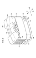
- FIG. 2 is an external perspective view of the charger according to the embodiment, showing the charger at the time of storage.
- FIG. 3 is an external perspective view of the charger according to the embodiment, showing the charger in use.
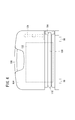
- FIG. 4 is an exterior rear view of the charger shown in FIG.
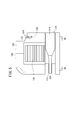
- FIG. 5 is an external side view of the charger shown in FIG.
- FIG. 6 is an external perspective view of the charger in the first modification.
- FIG. 7 is an external perspective view of the charger at the time of storage in the second modification.
- FIG. 8 is an external perspective view of the charger according to the third modification.
- FIG. 9 is an external perspective view of the charger at the time of storage in the fourth modification.
- FIG. 10 is an external side view of the charger in the fifth modification.
- Upper end portions of a pair of left and right side frames 30, 30 are connected to a substantially central portion in the vertical direction of the main frame 22, and the side frames 30 extend obliquely downward from there and bend horizontally and then extend horizontally.
- a 72V main battery 18 for supplying electric power to the electric motor 16 is disposed so as to be sandwiched between the horizontal portions of the left and right side frames 30.
- a horizontal portion of the side frame 30 rises obliquely rearward, is bent upward of the vehicle body, and is connected to the rear frame 32.
- a plurality of concave portions (for example, four concave portions) 98 are formed on the step floor 12, and a plurality of convex portions (for example, four convex portions) 99 to be fitted with the plurality of concave portions 98 are formed on the bottom of the charger 100. Is formed.
- the charger 100 is placed on the step floor 12 by the plurality of convex portions 99 formed on the bottom surface of the charger 100 and the plurality of recesses 98 formed on the step floor 12. It can be fixed.
- the second cord 118 and the upper end of the storage portion 120 rub against each other because the second cord 118 is stretched to the power outlet.
- a stress may be applied to the connection between the second cord 118 and the charger body 102, and the second cord 118 may be detached from the charger body 102.
- the second cord 118 and the upper end of the storage portion 120 are held by holding the second cord 118 in the first holding portion 128 (by fitting the second cord 118 into the groove). It is possible to reduce the stress applied to the connecting portion between the second cord 118 and the charger body 102 by pulling the second cord 118 without rubbing. Accordingly, the durability of the end portion of the housing portion 120 and the second cord 118 is improved, and the durability of the charger 100 is also improved.
- a second holding portion 146 for holding the plug 124 of the second cord 118 may be provided around the upper portion of the storage portion 120.
- the second holding portion 146 holds the plug 124 by sandwiching the plug 124 from both sides in the width direction of the plug 124.
- the second holding unit 146 may hold the plug 124 by supporting the plug 124 from below. Since the second holding portion 146 is provided, it is possible to prevent the second cord 118 from jumping out of the storage portion 120 even when the charger 100 is held and moved.
Landscapes
- Engineering & Computer Science (AREA)
- Power Engineering (AREA)
- Transportation (AREA)
- Mechanical Engineering (AREA)
- Microelectronics & Electronic Packaging (AREA)
- Charge And Discharge Circuits For Batteries Or The Like (AREA)
- Electric Propulsion And Braking For Vehicles (AREA)
- Secondary Cells (AREA)
Abstract
Priority Applications (5)
| Application Number | Priority Date | Filing Date | Title |
|---|---|---|---|
| BR112013004772A BR112013004772A2 (pt) | 2010-08-31 | 2011-08-12 | carregador |
| US13/818,783 US9433113B2 (en) | 2010-08-31 | 2011-08-12 | Charger |
| CN201180041693.3A CN103081279B (zh) | 2010-08-31 | 2011-08-12 | 充电器 |
| ES11821550.8T ES2574915T3 (es) | 2010-08-31 | 2011-08-12 | Cargador |
| EP11821550.8A EP2613418B1 (fr) | 2010-08-31 | 2011-08-12 | Chargeur |
Applications Claiming Priority (2)
| Application Number | Priority Date | Filing Date | Title |
|---|---|---|---|
| JP2010-195022 | 2010-08-31 | ||
| JP2010195022A JP5456623B2 (ja) | 2010-08-31 | 2010-08-31 | 充電器 |
Publications (1)
| Publication Number | Publication Date |
|---|---|
| WO2012029532A1 true WO2012029532A1 (fr) | 2012-03-08 |
Family
ID=45772637
Family Applications (1)
| Application Number | Title | Priority Date | Filing Date |
|---|---|---|---|
| PCT/JP2011/068463 WO2012029532A1 (fr) | 2010-08-31 | 2011-08-12 | Chargeur |
Country Status (8)
| Country | Link |
|---|---|
| US (1) | US9433113B2 (fr) |
| EP (1) | EP2613418B1 (fr) |
| JP (1) | JP5456623B2 (fr) |
| CN (1) | CN103081279B (fr) |
| BR (1) | BR112013004772A2 (fr) |
| ES (1) | ES2574915T3 (fr) |
| TW (1) | TWI477025B (fr) |
| WO (1) | WO2012029532A1 (fr) |
Families Citing this family (8)
| Publication number | Priority date | Publication date | Assignee | Title |
|---|---|---|---|---|
| CN104380562A (zh) * | 2012-06-20 | 2015-02-25 | 株式会社牧田 | 充电器 |
| WO2015104955A1 (fr) * | 2014-01-07 | 2015-07-16 | 住友ゴム工業株式会社 | Pneumatique |
| US20160126765A1 (en) * | 2014-03-25 | 2016-05-05 | Tek Global S.R.L. | Apparatus And Method For Charging Batteries |
| CN107888022B (zh) * | 2017-11-15 | 2024-04-09 | 昆山唐泽新能源科技有限公司 | 发电花鼓及使用它的车辆 |
| DE102018201375A1 (de) * | 2018-01-30 | 2019-08-01 | Robert Bosch Gmbh | Batteriemodul, Batteriepack dieses enthaltend, sowie deren Verwendung |
| WO2020165936A1 (fr) * | 2019-02-12 | 2020-08-20 | 三菱電機株式会社 | Dispositif de charge/décharge de véhicule |
| DE102020104736A1 (de) * | 2020-02-24 | 2021-08-26 | Audi Aktiengesellschaft | Kraftfahrzeug umfassend eine Ladeeinrichtung |
| US11623535B1 (en) | 2022-05-04 | 2023-04-11 | Beta Air, Llc | Methods and systems for charging an electric aircraft including a horizontal cable arrangement |
Citations (6)
| Publication number | Priority date | Publication date | Assignee | Title |
|---|---|---|---|---|
| JPS55173191U (fr) * | 1979-05-28 | 1980-12-12 | ||
| JPS5960835U (ja) * | 1982-10-15 | 1984-04-20 | スタンレー電気株式会社 | コ−ド収納式充電器 |
| JPH0497438U (fr) * | 1991-01-10 | 1992-08-24 | ||
| JPH11321753A (ja) * | 1998-05-18 | 1999-11-24 | Yamaha Motor Co Ltd | 電動車両における充電器の配置構造 |
| JP2004079320A (ja) | 2002-08-16 | 2004-03-11 | Yamaha Motor Co Ltd | 充電器構造 |
| JP3142979U (ja) * | 2008-04-22 | 2008-07-03 | 隆樹 櫻井 | 携帯電話充電用acアダプター |
Family Cites Families (4)
| Publication number | Priority date | Publication date | Assignee | Title |
|---|---|---|---|---|
| JPS5960835A (ja) | 1982-09-29 | 1984-04-06 | 日立照明株式会社 | 振動検知スイツチ |
| US6002235A (en) * | 1999-02-17 | 1999-12-14 | Bonnet Enterprises Llc | Battery jump starter with jaw securing means |
| CN201017966Y (zh) * | 2007-03-07 | 2008-02-06 | 温州大学 | 便携充电器 |
| US20110169447A1 (en) * | 2010-01-11 | 2011-07-14 | Leviton Manufacturing Co., Inc. | Electric vehicle supply equipment |
-
2010
- 2010-08-31 JP JP2010195022A patent/JP5456623B2/ja active Active
-
2011
- 2011-08-12 WO PCT/JP2011/068463 patent/WO2012029532A1/fr active Application Filing
- 2011-08-12 BR BR112013004772A patent/BR112013004772A2/pt active Search and Examination
- 2011-08-12 EP EP11821550.8A patent/EP2613418B1/fr not_active Not-in-force
- 2011-08-12 US US13/818,783 patent/US9433113B2/en not_active Expired - Fee Related
- 2011-08-12 ES ES11821550.8T patent/ES2574915T3/es active Active
- 2011-08-12 CN CN201180041693.3A patent/CN103081279B/zh active Active
- 2011-08-29 TW TW100130859A patent/TWI477025B/zh not_active IP Right Cessation
Patent Citations (6)
| Publication number | Priority date | Publication date | Assignee | Title |
|---|---|---|---|---|
| JPS55173191U (fr) * | 1979-05-28 | 1980-12-12 | ||
| JPS5960835U (ja) * | 1982-10-15 | 1984-04-20 | スタンレー電気株式会社 | コ−ド収納式充電器 |
| JPH0497438U (fr) * | 1991-01-10 | 1992-08-24 | ||
| JPH11321753A (ja) * | 1998-05-18 | 1999-11-24 | Yamaha Motor Co Ltd | 電動車両における充電器の配置構造 |
| JP2004079320A (ja) | 2002-08-16 | 2004-03-11 | Yamaha Motor Co Ltd | 充電器構造 |
| JP3142979U (ja) * | 2008-04-22 | 2008-07-03 | 隆樹 櫻井 | 携帯電話充電用acアダプター |
Non-Patent Citations (1)
| Title |
|---|
| See also references of EP2613418A4 |
Also Published As
| Publication number | Publication date |
|---|---|
| JP2012055076A (ja) | 2012-03-15 |
| JP5456623B2 (ja) | 2014-04-02 |
| EP2613418A4 (fr) | 2014-07-16 |
| EP2613418B1 (fr) | 2016-05-25 |
| TW201230594A (en) | 2012-07-16 |
| CN103081279A (zh) | 2013-05-01 |
| CN103081279B (zh) | 2015-06-17 |
| EP2613418A1 (fr) | 2013-07-10 |
| BR112013004772A2 (pt) | 2016-08-09 |
| TWI477025B (zh) | 2015-03-11 |
| US9433113B2 (en) | 2016-08-30 |
| US20130148280A1 (en) | 2013-06-13 |
| ES2574915T3 (es) | 2016-06-23 |
Similar Documents
| Publication | Publication Date | Title |
|---|---|---|
| WO2012029532A1 (fr) | Chargeur | |
| TWI546211B (zh) | 充電器及充電器之安裝構造 | |
| JP5728591B2 (ja) | 電動車両 | |
| EP2479094B1 (fr) | Véhicule à deux roues à propulsion électrique | |
| JP5680431B2 (ja) | 自動二輪車 | |
| JP5342515B2 (ja) | 充電口構造および鞍乗り型車両 | |
| JP5778885B2 (ja) | 電動二輪車のバッテリ装置 | |
| EP2623404A1 (fr) | Véhicule électrique à deux roues | |
| JP5614047B2 (ja) | 電動式自動二輪車 | |
| WO2011033613A1 (fr) | Structure de câblage pour véhicule électrique à deux ou trois roues | |
| JP5624002B2 (ja) | 鞍乗り型車両のモバイル端末支持構造 | |
| WO2014192587A1 (fr) | Structure de stockage d'articles pour véhicules à deux roues automatiques | |
| JP5254164B2 (ja) | 電動二輪車 | |
| TWI507308B (zh) | Electric vehicle | |
| JP6290774B2 (ja) | 鞍乗り型電動車両 | |
| JP5576536B2 (ja) | 充電器 | |
| JP6121391B2 (ja) | 鞍乗り型電動車両 | |
| JP5421995B2 (ja) | 充電器の取付け構造 | |
| JPH11321753A (ja) | 電動車両における充電器の配置構造 | |
| CN205872318U (zh) | 可伸缩的电动车及其可伸缩的车架 | |
| JP2011063073A (ja) | 自動二輪車 |
Legal Events
| Date | Code | Title | Description |
|---|---|---|---|
| WWE | Wipo information: entry into national phase |
Ref document number: 201180041693.3 Country of ref document: CN |
|
| 121 | Ep: the epo has been informed by wipo that ep was designated in this application |
Ref document number: 11821550 Country of ref document: EP Kind code of ref document: A1 |
|
| WWE | Wipo information: entry into national phase |
Ref document number: 13818783 Country of ref document: US Ref document number: 2011821550 Country of ref document: EP |
|
| NENP | Non-entry into the national phase |
Ref country code: DE |
|
| REG | Reference to national code |
Ref country code: BR Ref legal event code: B01A Ref document number: 112013004772 Country of ref document: BR |
|
| ENP | Entry into the national phase |
Ref document number: 112013004772 Country of ref document: BR Kind code of ref document: A2 Effective date: 20130227 |