WO2012029532A1 - Charger - Google Patents
Charger Download PDFInfo
- Publication number
- WO2012029532A1 WO2012029532A1 PCT/JP2011/068463 JP2011068463W WO2012029532A1 WO 2012029532 A1 WO2012029532 A1 WO 2012029532A1 JP 2011068463 W JP2011068463 W JP 2011068463W WO 2012029532 A1 WO2012029532 A1 WO 2012029532A1
- Authority
- WO
- WIPO (PCT)
- Prior art keywords
- charger
- cord
- storage
- plug
- battery
- Prior art date
Links
Images


Classifications
-
- B—PERFORMING OPERATIONS; TRANSPORTING
- B60—VEHICLES IN GENERAL
- B60L—PROPULSION OF ELECTRICALLY-PROPELLED VEHICLES; SUPPLYING ELECTRIC POWER FOR AUXILIARY EQUIPMENT OF ELECTRICALLY-PROPELLED VEHICLES; ELECTRODYNAMIC BRAKE SYSTEMS FOR VEHICLES IN GENERAL; MAGNETIC SUSPENSION OR LEVITATION FOR VEHICLES; MONITORING OPERATING VARIABLES OF ELECTRICALLY-PROPELLED VEHICLES; ELECTRIC SAFETY DEVICES FOR ELECTRICALLY-PROPELLED VEHICLES
- B60L53/00—Methods of charging batteries, specially adapted for electric vehicles; Charging stations or on-board charging equipment therefor; Exchange of energy storage elements in electric vehicles
- B60L53/10—Methods of charging batteries, specially adapted for electric vehicles; Charging stations or on-board charging equipment therefor; Exchange of energy storage elements in electric vehicles characterised by the energy transfer between the charging station and the vehicle
- B60L53/14—Conductive energy transfer
-
- B—PERFORMING OPERATIONS; TRANSPORTING
- B60—VEHICLES IN GENERAL
- B60L—PROPULSION OF ELECTRICALLY-PROPELLED VEHICLES; SUPPLYING ELECTRIC POWER FOR AUXILIARY EQUIPMENT OF ELECTRICALLY-PROPELLED VEHICLES; ELECTRODYNAMIC BRAKE SYSTEMS FOR VEHICLES IN GENERAL; MAGNETIC SUSPENSION OR LEVITATION FOR VEHICLES; MONITORING OPERATING VARIABLES OF ELECTRICALLY-PROPELLED VEHICLES; ELECTRIC SAFETY DEVICES FOR ELECTRICALLY-PROPELLED VEHICLES
- B60L53/00—Methods of charging batteries, specially adapted for electric vehicles; Charging stations or on-board charging equipment therefor; Exchange of energy storage elements in electric vehicles
- B60L53/20—Methods of charging batteries, specially adapted for electric vehicles; Charging stations or on-board charging equipment therefor; Exchange of energy storage elements in electric vehicles characterised by converters located in the vehicle
- B60L53/22—Constructional details or arrangements of charging converters specially adapted for charging electric vehicles
-
- H—ELECTRICITY
- H02—GENERATION; CONVERSION OR DISTRIBUTION OF ELECTRIC POWER
- H02J—CIRCUIT ARRANGEMENTS OR SYSTEMS FOR SUPPLYING OR DISTRIBUTING ELECTRIC POWER; SYSTEMS FOR STORING ELECTRIC ENERGY
- H02J7/00—Circuit arrangements for charging or depolarising batteries or for supplying loads from batteries
- H02J7/0042—Circuit arrangements for charging or depolarising batteries or for supplying loads from batteries characterised by the mechanical construction
-
- H—ELECTRICITY
- H05—ELECTRIC TECHNIQUES NOT OTHERWISE PROVIDED FOR
- H05K—PRINTED CIRCUITS; CASINGS OR CONSTRUCTIONAL DETAILS OF ELECTRIC APPARATUS; MANUFACTURE OF ASSEMBLAGES OF ELECTRICAL COMPONENTS
- H05K5/00—Casings, cabinets or drawers for electric apparatus
- H05K5/02—Details
-
- H—ELECTRICITY
- H01—ELECTRIC ELEMENTS
- H01M—PROCESSES OR MEANS, e.g. BATTERIES, FOR THE DIRECT CONVERSION OF CHEMICAL ENERGY INTO ELECTRICAL ENERGY
- H01M10/00—Secondary cells; Manufacture thereof
- H01M10/42—Methods or arrangements for servicing or maintenance of secondary cells or secondary half-cells
- H01M10/4207—Methods or arrangements for servicing or maintenance of secondary cells or secondary half-cells for several batteries or cells simultaneously or sequentially
-
- H—ELECTRICITY
- H01—ELECTRIC ELEMENTS
- H01M—PROCESSES OR MEANS, e.g. BATTERIES, FOR THE DIRECT CONVERSION OF CHEMICAL ENERGY INTO ELECTRICAL ENERGY
- H01M10/00—Secondary cells; Manufacture thereof
- H01M10/42—Methods or arrangements for servicing or maintenance of secondary cells or secondary half-cells
- H01M10/46—Accumulators structurally combined with charging apparatus
-
- H—ELECTRICITY
- H01—ELECTRIC ELEMENTS
- H01M—PROCESSES OR MEANS, e.g. BATTERIES, FOR THE DIRECT CONVERSION OF CHEMICAL ENERGY INTO ELECTRICAL ENERGY
- H01M16/00—Structural combinations of different types of electrochemical generators
-
- H—ELECTRICITY
- H01—ELECTRIC ELEMENTS
- H01M—PROCESSES OR MEANS, e.g. BATTERIES, FOR THE DIRECT CONVERSION OF CHEMICAL ENERGY INTO ELECTRICAL ENERGY
- H01M2220/00—Batteries for particular applications
- H01M2220/20—Batteries in motive systems, e.g. vehicle, ship, plane
-
- Y—GENERAL TAGGING OF NEW TECHNOLOGICAL DEVELOPMENTS; GENERAL TAGGING OF CROSS-SECTIONAL TECHNOLOGIES SPANNING OVER SEVERAL SECTIONS OF THE IPC; TECHNICAL SUBJECTS COVERED BY FORMER USPC CROSS-REFERENCE ART COLLECTIONS [XRACs] AND DIGESTS
- Y02—TECHNOLOGIES OR APPLICATIONS FOR MITIGATION OR ADAPTATION AGAINST CLIMATE CHANGE
- Y02E—REDUCTION OF GREENHOUSE GAS [GHG] EMISSIONS, RELATED TO ENERGY GENERATION, TRANSMISSION OR DISTRIBUTION
- Y02E60/00—Enabling technologies; Technologies with a potential or indirect contribution to GHG emissions mitigation
- Y02E60/10—Energy storage using batteries
-
- Y—GENERAL TAGGING OF NEW TECHNOLOGICAL DEVELOPMENTS; GENERAL TAGGING OF CROSS-SECTIONAL TECHNOLOGIES SPANNING OVER SEVERAL SECTIONS OF THE IPC; TECHNICAL SUBJECTS COVERED BY FORMER USPC CROSS-REFERENCE ART COLLECTIONS [XRACs] AND DIGESTS
- Y02—TECHNOLOGIES OR APPLICATIONS FOR MITIGATION OR ADAPTATION AGAINST CLIMATE CHANGE
- Y02T—CLIMATE CHANGE MITIGATION TECHNOLOGIES RELATED TO TRANSPORTATION
- Y02T10/00—Road transport of goods or passengers
- Y02T10/60—Other road transportation technologies with climate change mitigation effect
- Y02T10/70—Energy storage systems for electromobility, e.g. batteries
-
- Y—GENERAL TAGGING OF NEW TECHNOLOGICAL DEVELOPMENTS; GENERAL TAGGING OF CROSS-SECTIONAL TECHNOLOGIES SPANNING OVER SEVERAL SECTIONS OF THE IPC; TECHNICAL SUBJECTS COVERED BY FORMER USPC CROSS-REFERENCE ART COLLECTIONS [XRACs] AND DIGESTS
- Y02—TECHNOLOGIES OR APPLICATIONS FOR MITIGATION OR ADAPTATION AGAINST CLIMATE CHANGE
- Y02T—CLIMATE CHANGE MITIGATION TECHNOLOGIES RELATED TO TRANSPORTATION
- Y02T10/00—Road transport of goods or passengers
- Y02T10/60—Other road transportation technologies with climate change mitigation effect
- Y02T10/7072—Electromobility specific charging systems or methods for batteries, ultracapacitors, supercapacitors or double-layer capacitors
-
- Y—GENERAL TAGGING OF NEW TECHNOLOGICAL DEVELOPMENTS; GENERAL TAGGING OF CROSS-SECTIONAL TECHNOLOGIES SPANNING OVER SEVERAL SECTIONS OF THE IPC; TECHNICAL SUBJECTS COVERED BY FORMER USPC CROSS-REFERENCE ART COLLECTIONS [XRACs] AND DIGESTS
- Y02—TECHNOLOGIES OR APPLICATIONS FOR MITIGATION OR ADAPTATION AGAINST CLIMATE CHANGE
- Y02T—CLIMATE CHANGE MITIGATION TECHNOLOGIES RELATED TO TRANSPORTATION
- Y02T90/00—Enabling technologies or technologies with a potential or indirect contribution to GHG emissions mitigation
- Y02T90/10—Technologies relating to charging of electric vehicles
- Y02T90/12—Electric charging stations
-
- Y—GENERAL TAGGING OF NEW TECHNOLOGICAL DEVELOPMENTS; GENERAL TAGGING OF CROSS-SECTIONAL TECHNOLOGIES SPANNING OVER SEVERAL SECTIONS OF THE IPC; TECHNICAL SUBJECTS COVERED BY FORMER USPC CROSS-REFERENCE ART COLLECTIONS [XRACs] AND DIGESTS
- Y02—TECHNOLOGIES OR APPLICATIONS FOR MITIGATION OR ADAPTATION AGAINST CLIMATE CHANGE
- Y02T—CLIMATE CHANGE MITIGATION TECHNOLOGIES RELATED TO TRANSPORTATION
- Y02T90/00—Enabling technologies or technologies with a potential or indirect contribution to GHG emissions mitigation
- Y02T90/10—Technologies relating to charging of electric vehicles
- Y02T90/14—Plug-in electric vehicles
Definitions
- the present invention relates to a charger attachment structure that improves the storability of a cord connected to the charger.
- the AC cord and the DC cord connected to the charger are extended out from the inside of the charger body, and the cord is wound along the cord extension direction Japanese Patent Application Laid-Open No. 2004-079320 is described.
- this invention is made in view of the conventional problem which concerns, It aims at providing the charger which improved the storability of the code
- the invention according to claim 4 is the battery charger according to claim 1, characterized in that a protective portion for protecting the upper end is provided on the upper end of the storage portion.
- the invention according to claim 5 is the battery charger according to claim 1, characterized in that a first holding portion for holding the second cord is provided around the upper portion of the storage portion.
- the invention according to claim 8 is the battery charger according to claim 1, characterized in that a lid portion covering the opening of the storage portion is provided on the upper portion of the storage portion.
- the invention according to claim 9 is the charger according to claim 1, wherein the storage portion is opened at an upper side of the charger along a longitudinal direction of a handle portion provided on the upper portion of the charger.
- the winding recess may be circumferentially formed on at least a side surface of the lower half of the charger and at least a side surface of the charger.
- the second holding portion for holding the plug of the second cord is provided around the upper portion of the storage portion, so that the second cord is stored when the charger is moved by hand. It can prevent jumping out of the department.
- FIG. 1 is a side view showing the main part structure of the electric motorcycle according to the embodiment.
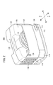
- FIG. 2 is an external perspective view of the charger according to the embodiment, showing the charger at the time of storage.
- FIG. 3 is an external perspective view of the charger according to the embodiment, showing the charger in use.
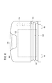
- FIG. 4 is an exterior rear view of the charger shown in FIG.
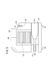
- FIG. 5 is an external side view of the charger shown in FIG.
- FIG. 6 is an external perspective view of the charger in the first modification.
- FIG. 7 is an external perspective view of the charger at the time of storage in the second modification.
- FIG. 8 is an external perspective view of the charger according to the third modification.
- FIG. 9 is an external perspective view of the charger at the time of storage in the fourth modification.
- FIG. 10 is an external side view of the charger in the fifth modification.
- Upper end portions of a pair of left and right side frames 30, 30 are connected to a substantially central portion in the vertical direction of the main frame 22, and the side frames 30 extend obliquely downward from there and bend horizontally and then extend horizontally.
- a 72V main battery 18 for supplying electric power to the electric motor 16 is disposed so as to be sandwiched between the horizontal portions of the left and right side frames 30.
- a horizontal portion of the side frame 30 rises obliquely rearward, is bent upward of the vehicle body, and is connected to the rear frame 32.
- a plurality of concave portions (for example, four concave portions) 98 are formed on the step floor 12, and a plurality of convex portions (for example, four convex portions) 99 to be fitted with the plurality of concave portions 98 are formed on the bottom of the charger 100. Is formed.
- the charger 100 is placed on the step floor 12 by the plurality of convex portions 99 formed on the bottom surface of the charger 100 and the plurality of recesses 98 formed on the step floor 12. It can be fixed.
- the second cord 118 and the upper end of the storage portion 120 rub against each other because the second cord 118 is stretched to the power outlet.
- a stress may be applied to the connection between the second cord 118 and the charger body 102, and the second cord 118 may be detached from the charger body 102.
- the second cord 118 and the upper end of the storage portion 120 are held by holding the second cord 118 in the first holding portion 128 (by fitting the second cord 118 into the groove). It is possible to reduce the stress applied to the connecting portion between the second cord 118 and the charger body 102 by pulling the second cord 118 without rubbing. Accordingly, the durability of the end portion of the housing portion 120 and the second cord 118 is improved, and the durability of the charger 100 is also improved.
- a second holding portion 146 for holding the plug 124 of the second cord 118 may be provided around the upper portion of the storage portion 120.
- the second holding portion 146 holds the plug 124 by sandwiching the plug 124 from both sides in the width direction of the plug 124.
- the second holding unit 146 may hold the plug 124 by supporting the plug 124 from below. Since the second holding portion 146 is provided, it is possible to prevent the second cord 118 from jumping out of the storage portion 120 even when the charger 100 is held and moved.
Abstract
Description
上記実施の形態では、収納部の上部に第2コード118を保持する第1保持部128を設けるようにしたが、第1保持部128を設けないようにしてもよい。この場合は、第2コード118と収納カバー122の上端との摩擦によって第2コード118及び収納カバー122に生じる傷や毀損を防止するために、図6に示すように、収納部120の上端、つまり、収納カバー122の上端に、該上端を保護する保護部140を設ける。この保護部140は、樹脂材料等からできた弾性部材である。なお、第1保持部128を設けながら、収納カバー122の上端に保護部140を設けるようにしてもよい。 (Modification 1)
In the above embodiment, the
上記実施の形態及び変形例1では、第1保持部128は、充電器100の使用時に第2コード118を保持するために設けられたものであるが、図7に示すように、充電器100の未使用時に、収納部120に収納された第2コード118を保持するために用いられてもよい。これにより、充電器100を手で運ぶことによって、第2コード118が収納部120から飛び出すことを防止することができる。 (Modification 2)
In the above embodiment and the first modification, the
上記実施の形態及び変形例1、2では、収納カバー122の上端に溝を設けることで第1保持部128を形成したが、図8に示すように収納カバー122とは別体の第1保持部142を収納部120の上部周辺に設けるようにしてもよい。第1保持部142は、クリップ状の形状を有し、第2コード118を挟み込むことで第2コード118を保持する。第1保持部142が第2コード118を保持することで、充電器100の使用時に第2コード118と収納部120の上端とが擦れることなく、第2コード118及び収納部120の耐久性を向上させることができる。 (Modification 3)
Although the
変形例4では、更に、図9に示すように収納部120の上部周辺に第2コード118のプラグ124を保持する第2保持部146を設けるようにしてもよい。第2保持部146は、プラグ124の幅方向の両側からプラグ124を挟み込むことで、プラグ124を保持する。なお、第2保持部146は、プラグ124を下から支えることでプラグ124を保持してもよい。第2保持部146を設けるので、充電器100を手に持って移動する場合であっても、第2コード118が収納部120から飛び出すことを防止することができる。 (Modification 4)
In the fourth modification, as shown in FIG. 9, a
変形例5では、更に、図10に示すように収納部120の上部に、収納部120の開口を覆う蓋部148を設け、該蓋部148と、収納部120の上端、つまり収納カバー122の上端とは、ヒンジ150を介して回動可能に接続されている。これにより、第2コード118を収納部120に収納した後に、蓋部148で収納部120の開口を覆うことで、充電器100を手に持って移動した場合であっても、第2コード118が収納部120から飛び出すことを防ぐことができる。 (Modification 5)
In the fifth modification, as shown in FIG. 10, a
充電器100は、上記変形例1~5を任意に組み合わせた態様であってもよい。 (Modification 6)
The
Claims (10)
- 充電器本体(102)を収納する収納ケース(104)と、
前記収納ケース(104)の外周に形成され、前記充電器本体(102)に接続される第1コード(108)を巻き掛けることができる巻き掛け用凹部(110)と、
前記収納ケース(104)に設けられ、前記第1コード(108)の先端に接続されるプラグ(114)を収納するプラグ用凹部(116)と、
を備え、
前記充電器本体(102)に接続される第2コード(118)を収納する、上方向に開口した収納部(120)を前記収納ケース(104)に設けたことを特徴とする充電器(100)。 A storage case (104) for storing the charger body (102);
A winding recess (110) formed on an outer periphery of the storage case (104) and capable of winding a first cord (108) connected to the charger body (102);
A plug recess (116) provided in the storage case (104) and storing a plug (114) connected to the tip of the first cord (108);
Equipped with
A battery charger (100) is characterized in that the storage case (104) is provided with an upwardly open storage portion (120) for storing the second cord (118) connected to the charger body (102). ). - 請求項1に記載の充電器(100)であって、
前記第1コード(108)は、バッテリ(18)の充電用コードであり、
前記第2コード(118)は、電源用コードであることを特徴とする充電器(100)。 A charger (100) according to claim 1, wherein
The first cord (108) is a cord for charging the battery (18),
The second cord (118) is a power cord, and the charger (100). - 請求項2に記載の充電器(100)であって、
前記第2コード(118)は、前記第1コード(108)より長いことを特徴とする充電器(100)。 The charger (100) according to claim 2, wherein
A charger (100) characterized in that the second cord (118) is longer than the first cord (108). - 請求項1に記載の充電器(100)であって、
前記収納部(120)の上端に、該上端を保護する保護部(140)を設けることを特徴とする充電器(100)。 A charger (100) according to claim 1, wherein
A charger (100) comprising a protection portion (140) for protecting the upper end of the storage portion (120). - 請求項1に記載の充電器(100)であって、
前記収納部(120)の上部周辺に、前記第2コード(118)を保持する第1保持部(128、142)を設けることを特徴とする充電器(100)。 A charger (100) according to claim 1, wherein
A charger (100) characterized in that a first holding part (128, 142) for holding the second cord (118) is provided around the upper part of the storage part (120). - 請求項5に記載の充電器(100)であって、
前記第1保持部(128、142)には、保護部材(132、144)が設けられていることを特徴とする充電器(100)。 A charger (100) according to claim 5, wherein
A charger (100) characterized in that the first holding portion (128, 142) is provided with a protective member (132, 144). - 請求項1に記載の充電器(100)であって、
前記収納部(120)の上部周辺に、前記第2コード(118)のプラグ(124)を保持する第2保持部(146)を設けることを特徴とする充電器(100)。 A charger (100) according to claim 1, wherein
A charger (100) characterized in that a second holding part (146) for holding the plug (124) of the second cord (118) is provided around the upper part of the storage part (120). - 請求項1に記載の充電器(100)であって、
前記収納部(120)の上部に、前記収納部(120)の開口を覆う蓋部(148)を設けることを特徴とする充電器(100)。 A charger (100) according to claim 1, wherein
A battery charger (100) comprising a lid (148) covering an opening of the storage portion (120) above the storage portion (120). - 請求項1に記載の充電器(100)であって、
前記収納部(120)は、前記充電器(100)の上部に設けられる把手部(106)の長手方向に沿って前記充電器(100)の側上部に開口し、前記巻き掛け用凹部(110)は、前記充電器(100)の下半分であって前記充電器(100)の少なくとも側面に亘って周回状に形成されることを特徴とする充電器(100)。 A charger (100) according to claim 1, wherein
The storage portion (120) is opened on the upper side of the charger (100) along the longitudinal direction of the handle portion (106) provided on the upper portion of the charger (100), and the winding recess (110) The charger (100) is formed in the lower half of the charger (100) and at least around the side surface of the charger (100). - 請求項1に記載の充電器(100)であって、
前記充電器(100)は、鞍乗型電動車両(10)に搭載されるバッテリ(18)を受電する充電器(100)であって、前記第1コード(108)の前記プラグ(114)は、前記バッテリ(18)と接続される充電コネクタ(20)と接続され、前記第2コード(118)は、電源コンセントに接続されるとともに、前記充電器(100)は、前記バッテリ(18)に充電を行う場合は、前記鞍乗型電動車両(10)の低床式フロア(12)に載置されることを特徴とする充電器(100)。 A charger (100) according to claim 1, wherein
The charger (100) is a charger (100) for receiving a battery (18) mounted on a straddle-type electric vehicle (10), and the plug (114) of the first cord (108) is A charging connector (20) connected to the battery (18), the second cord (118) is connected to a power outlet, and the charger (100) is connected to the battery (18) When charging is performed, the battery charger (100) is placed on a low floor type floor (12) of the straddle-type electric vehicle (10).
Priority Applications (5)
| Application Number | Priority Date | Filing Date | Title |
|---|---|---|---|
| BR112013004772A BR112013004772A2 (en) | 2010-08-31 | 2011-08-12 | loader |
| US13/818,783 US9433113B2 (en) | 2010-08-31 | 2011-08-12 | Charger |
| CN201180041693.3A CN103081279B (en) | 2010-08-31 | 2011-08-12 | Charger |
| ES11821550.8T ES2574915T3 (en) | 2010-08-31 | 2011-08-12 | Charger |
| EP11821550.8A EP2613418B1 (en) | 2010-08-31 | 2011-08-12 | Charger |
Applications Claiming Priority (2)
| Application Number | Priority Date | Filing Date | Title |
|---|---|---|---|
| JP2010195022A JP5456623B2 (en) | 2010-08-31 | 2010-08-31 | Charger |
| JP2010-195022 | 2010-08-31 |
Publications (1)
| Publication Number | Publication Date |
|---|---|
| WO2012029532A1 true WO2012029532A1 (en) | 2012-03-08 |
Family
ID=45772637
Family Applications (1)
| Application Number | Title | Priority Date | Filing Date |
|---|---|---|---|
| PCT/JP2011/068463 WO2012029532A1 (en) | 2010-08-31 | 2011-08-12 | Charger |
Country Status (8)
| Country | Link |
|---|---|
| US (1) | US9433113B2 (en) |
| EP (1) | EP2613418B1 (en) |
| JP (1) | JP5456623B2 (en) |
| CN (1) | CN103081279B (en) |
| BR (1) | BR112013004772A2 (en) |
| ES (1) | ES2574915T3 (en) |
| TW (1) | TWI477025B (en) |
| WO (1) | WO2012029532A1 (en) |
Families Citing this family (8)
| Publication number | Priority date | Publication date | Assignee | Title |
|---|---|---|---|---|
| CN104380562A (en) * | 2012-06-20 | 2015-02-25 | 株式会社牧田 | Charger |
| EP3081587B1 (en) * | 2014-01-07 | 2022-06-08 | Sumitomo Rubber Industries, Ltd. | Pneumatic tire |
| JP2017511108A (en) * | 2014-03-25 | 2017-04-13 | テック、グローバル、ソシエタ、レスポンサビリタ、リミタータTek Global S.R.L. | Apparatus and method for charging a battery |
| CN107888022B (en) * | 2017-11-15 | 2024-04-09 | 昆山唐泽新能源科技有限公司 | Power generation hub and vehicle using same |
| DE102018201375A1 (en) * | 2018-01-30 | 2019-08-01 | Robert Bosch Gmbh | Battery module, battery pack containing this, as well as their use |
| CN111819753A (en) * | 2019-02-12 | 2020-10-23 | 三菱电机株式会社 | Vehicle charging/discharging device |
| DE102020104736A1 (en) * | 2020-02-24 | 2021-08-26 | Audi Aktiengesellschaft | Motor vehicle comprising a charging device |
| US11623535B1 (en) | 2022-05-04 | 2023-04-11 | Beta Air, Llc | Methods and systems for charging an electric aircraft including a horizontal cable arrangement |
Citations (6)
| Publication number | Priority date | Publication date | Assignee | Title |
|---|---|---|---|---|
| JPS55173191U (en) * | 1979-05-28 | 1980-12-12 | ||
| JPS5960835U (en) * | 1982-10-15 | 1984-04-20 | スタンレー電気株式会社 | Cord storage charger |
| JPH0497438U (en) * | 1991-01-10 | 1992-08-24 | ||
| JPH11321753A (en) * | 1998-05-18 | 1999-11-24 | Yamaha Motor Co Ltd | Charger arrangement structure for electric vehicle |
| JP2004079320A (en) | 2002-08-16 | 2004-03-11 | Yamaha Motor Co Ltd | Charger structure |
| JP3142979U (en) * | 2008-04-22 | 2008-07-03 | 隆樹 櫻井 | AC adapter for mobile phone charging |
Family Cites Families (4)
| Publication number | Priority date | Publication date | Assignee | Title |
|---|---|---|---|---|
| JPS5960835A (en) | 1982-09-29 | 1984-04-06 | 日立照明株式会社 | Vibration detecting switch |
| US6002235A (en) * | 1999-02-17 | 1999-12-14 | Bonnet Enterprises Llc | Battery jump starter with jaw securing means |
| CN201017966Y (en) * | 2007-03-07 | 2008-02-06 | 温州大学 | Portable charger |
| US20110169447A1 (en) * | 2010-01-11 | 2011-07-14 | Leviton Manufacturing Co., Inc. | Electric vehicle supply equipment |
-
2010
- 2010-08-31 JP JP2010195022A patent/JP5456623B2/en active Active
-
2011
- 2011-08-12 WO PCT/JP2011/068463 patent/WO2012029532A1/en active Application Filing
- 2011-08-12 US US13/818,783 patent/US9433113B2/en not_active Expired - Fee Related
- 2011-08-12 EP EP11821550.8A patent/EP2613418B1/en not_active Not-in-force
- 2011-08-12 ES ES11821550.8T patent/ES2574915T3/en active Active
- 2011-08-12 CN CN201180041693.3A patent/CN103081279B/en active Active
- 2011-08-12 BR BR112013004772A patent/BR112013004772A2/en active Search and Examination
- 2011-08-29 TW TW100130859A patent/TWI477025B/en not_active IP Right Cessation
Patent Citations (6)
| Publication number | Priority date | Publication date | Assignee | Title |
|---|---|---|---|---|
| JPS55173191U (en) * | 1979-05-28 | 1980-12-12 | ||
| JPS5960835U (en) * | 1982-10-15 | 1984-04-20 | スタンレー電気株式会社 | Cord storage charger |
| JPH0497438U (en) * | 1991-01-10 | 1992-08-24 | ||
| JPH11321753A (en) * | 1998-05-18 | 1999-11-24 | Yamaha Motor Co Ltd | Charger arrangement structure for electric vehicle |
| JP2004079320A (en) | 2002-08-16 | 2004-03-11 | Yamaha Motor Co Ltd | Charger structure |
| JP3142979U (en) * | 2008-04-22 | 2008-07-03 | 隆樹 櫻井 | AC adapter for mobile phone charging |
Non-Patent Citations (1)
| Title |
|---|
| See also references of EP2613418A4 |
Also Published As
| Publication number | Publication date |
|---|---|
| TWI477025B (en) | 2015-03-11 |
| JP2012055076A (en) | 2012-03-15 |
| US9433113B2 (en) | 2016-08-30 |
| ES2574915T3 (en) | 2016-06-23 |
| EP2613418B1 (en) | 2016-05-25 |
| EP2613418A4 (en) | 2014-07-16 |
| JP5456623B2 (en) | 2014-04-02 |
| BR112013004772A2 (en) | 2016-08-09 |
| CN103081279B (en) | 2015-06-17 |
| TW201230594A (en) | 2012-07-16 |
| CN103081279A (en) | 2013-05-01 |
| US20130148280A1 (en) | 2013-06-13 |
| EP2613418A1 (en) | 2013-07-10 |
Similar Documents
| Publication | Publication Date | Title |
|---|---|---|
| WO2012029532A1 (en) | Charger | |
| TWI546211B (en) | Electric charger and mounting structure for electric charger | |
| JP5728591B2 (en) | Electric vehicle | |
| EP2479094B1 (en) | Electrically driven two-wheeled vehicle | |
| JP5342515B2 (en) | Charging port structure and saddle-ride type vehicle | |
| JP5680431B2 (en) | Motorcycle | |
| JP5778885B2 (en) | Battery device for electric motorcycle | |
| EP2623404A1 (en) | Electric two-wheeled vehicle | |
| JP5614047B2 (en) | Electric motorcycle | |
| WO2011033613A1 (en) | Wiring structure for electrically powered two- or three-wheeled vehicle | |
| WO2014192587A1 (en) | Article storage structure for automatic two-wheeled vehicles | |
| JP5254164B2 (en) | Electric motorcycle | |
| TWI507308B (en) | Electric vehicle | |
| JP6290774B2 (en) | Saddle riding type electric vehicle | |
| JP5576536B2 (en) | Charger | |
| JP6121391B2 (en) | Saddle riding type electric vehicle | |
| JP5421995B2 (en) | Charger mounting structure | |
| JPH11321753A (en) | Charger arrangement structure for electric vehicle | |
| CN205872318U (en) | Telescopic electric motor car and telescopic frame thereof | |
| JP2011063073A (en) | Motorcycle |
Legal Events
| Date | Code | Title | Description |
|---|---|---|---|
| WWE | Wipo information: entry into national phase |
Ref document number: 201180041693.3 Country of ref document: CN |
|
| 121 | Ep: the epo has been informed by wipo that ep was designated in this application |
Ref document number: 11821550 Country of ref document: EP Kind code of ref document: A1 |
|
| WWE | Wipo information: entry into national phase |
Ref document number: 13818783 Country of ref document: US Ref document number: 2011821550 Country of ref document: EP |
|
| NENP | Non-entry into the national phase |
Ref country code: DE |
|
| REG | Reference to national code |
Ref country code: BR Ref legal event code: B01A Ref document number: 112013004772 Country of ref document: BR |
|
| ENP | Entry into the national phase |
Ref document number: 112013004772 Country of ref document: BR Kind code of ref document: A2 Effective date: 20130227 |