JP5254164B2 - Electric motorcycle - Google Patents
Electric motorcycle Download PDFInfo
- Publication number
- JP5254164B2 JP5254164B2 JP2009213691A JP2009213691A JP5254164B2 JP 5254164 B2 JP5254164 B2 JP 5254164B2 JP 2009213691 A JP2009213691 A JP 2009213691A JP 2009213691 A JP2009213691 A JP 2009213691A JP 5254164 B2 JP5254164 B2 JP 5254164B2
- Authority
- JP
- Japan
- Prior art keywords
- lid member
- side cover
- storage box
- state
- electric
- Prior art date
- Legal status (The legal status is an assumption and is not a legal conclusion. Google has not performed a legal analysis and makes no representation as to the accuracy of the status listed.)
- Expired - Fee Related
Links
Images


Classifications
-
- B—PERFORMING OPERATIONS; TRANSPORTING
- B60—VEHICLES IN GENERAL
- B60L—PROPULSION OF ELECTRICALLY-PROPELLED VEHICLES; SUPPLYING ELECTRIC POWER FOR AUXILIARY EQUIPMENT OF ELECTRICALLY-PROPELLED VEHICLES; ELECTRODYNAMIC BRAKE SYSTEMS FOR VEHICLES IN GENERAL; MAGNETIC SUSPENSION OR LEVITATION FOR VEHICLES; MONITORING OPERATING VARIABLES OF ELECTRICALLY-PROPELLED VEHICLES; ELECTRIC SAFETY DEVICES FOR ELECTRICALLY-PROPELLED VEHICLES
- B60L1/00—Supplying electric power to auxiliary equipment of vehicles
- B60L1/003—Supplying electric power to auxiliary equipment of vehicles to auxiliary motors, e.g. for pumps, compressors
-
- B—PERFORMING OPERATIONS; TRANSPORTING
- B60—VEHICLES IN GENERAL
- B60L—PROPULSION OF ELECTRICALLY-PROPELLED VEHICLES; SUPPLYING ELECTRIC POWER FOR AUXILIARY EQUIPMENT OF ELECTRICALLY-PROPELLED VEHICLES; ELECTRODYNAMIC BRAKE SYSTEMS FOR VEHICLES IN GENERAL; MAGNETIC SUSPENSION OR LEVITATION FOR VEHICLES; MONITORING OPERATING VARIABLES OF ELECTRICALLY-PROPELLED VEHICLES; ELECTRIC SAFETY DEVICES FOR ELECTRICALLY-PROPELLED VEHICLES
- B60L50/00—Electric propulsion with power supplied within the vehicle
- B60L50/50—Electric propulsion with power supplied within the vehicle using propulsion power supplied by batteries or fuel cells
- B60L50/60—Electric propulsion with power supplied within the vehicle using propulsion power supplied by batteries or fuel cells using power supplied by batteries
- B60L50/64—Constructional details of batteries specially adapted for electric vehicles
-
- B—PERFORMING OPERATIONS; TRANSPORTING
- B60—VEHICLES IN GENERAL
- B60L—PROPULSION OF ELECTRICALLY-PROPELLED VEHICLES; SUPPLYING ELECTRIC POWER FOR AUXILIARY EQUIPMENT OF ELECTRICALLY-PROPELLED VEHICLES; ELECTRODYNAMIC BRAKE SYSTEMS FOR VEHICLES IN GENERAL; MAGNETIC SUSPENSION OR LEVITATION FOR VEHICLES; MONITORING OPERATING VARIABLES OF ELECTRICALLY-PROPELLED VEHICLES; ELECTRIC SAFETY DEVICES FOR ELECTRICALLY-PROPELLED VEHICLES
- B60L50/00—Electric propulsion with power supplied within the vehicle
- B60L50/50—Electric propulsion with power supplied within the vehicle using propulsion power supplied by batteries or fuel cells
- B60L50/60—Electric propulsion with power supplied within the vehicle using propulsion power supplied by batteries or fuel cells using power supplied by batteries
- B60L50/66—Arrangements of batteries
-
- B—PERFORMING OPERATIONS; TRANSPORTING
- B60—VEHICLES IN GENERAL
- B60L—PROPULSION OF ELECTRICALLY-PROPELLED VEHICLES; SUPPLYING ELECTRIC POWER FOR AUXILIARY EQUIPMENT OF ELECTRICALLY-PROPELLED VEHICLES; ELECTRODYNAMIC BRAKE SYSTEMS FOR VEHICLES IN GENERAL; MAGNETIC SUSPENSION OR LEVITATION FOR VEHICLES; MONITORING OPERATING VARIABLES OF ELECTRICALLY-PROPELLED VEHICLES; ELECTRIC SAFETY DEVICES FOR ELECTRICALLY-PROPELLED VEHICLES
- B60L53/00—Methods of charging batteries, specially adapted for electric vehicles; Charging stations or on-board charging equipment therefor; Exchange of energy storage elements in electric vehicles
- B60L53/10—Methods of charging batteries, specially adapted for electric vehicles; Charging stations or on-board charging equipment therefor; Exchange of energy storage elements in electric vehicles characterised by the energy transfer between the charging station and the vehicle
- B60L53/14—Conductive energy transfer
- B60L53/16—Connectors, e.g. plugs or sockets, specially adapted for charging electric vehicles
-
- B—PERFORMING OPERATIONS; TRANSPORTING
- B60—VEHICLES IN GENERAL
- B60L—PROPULSION OF ELECTRICALLY-PROPELLED VEHICLES; SUPPLYING ELECTRIC POWER FOR AUXILIARY EQUIPMENT OF ELECTRICALLY-PROPELLED VEHICLES; ELECTRODYNAMIC BRAKE SYSTEMS FOR VEHICLES IN GENERAL; MAGNETIC SUSPENSION OR LEVITATION FOR VEHICLES; MONITORING OPERATING VARIABLES OF ELECTRICALLY-PROPELLED VEHICLES; ELECTRIC SAFETY DEVICES FOR ELECTRICALLY-PROPELLED VEHICLES
- B60L53/00—Methods of charging batteries, specially adapted for electric vehicles; Charging stations or on-board charging equipment therefor; Exchange of energy storage elements in electric vehicles
- B60L53/10—Methods of charging batteries, specially adapted for electric vehicles; Charging stations or on-board charging equipment therefor; Exchange of energy storage elements in electric vehicles characterised by the energy transfer between the charging station and the vehicle
- B60L53/14—Conductive energy transfer
- B60L53/18—Cables specially adapted for charging electric vehicles
-
- B—PERFORMING OPERATIONS; TRANSPORTING
- B60—VEHICLES IN GENERAL
- B60L—PROPULSION OF ELECTRICALLY-PROPELLED VEHICLES; SUPPLYING ELECTRIC POWER FOR AUXILIARY EQUIPMENT OF ELECTRICALLY-PROPELLED VEHICLES; ELECTRODYNAMIC BRAKE SYSTEMS FOR VEHICLES IN GENERAL; MAGNETIC SUSPENSION OR LEVITATION FOR VEHICLES; MONITORING OPERATING VARIABLES OF ELECTRICALLY-PROPELLED VEHICLES; ELECTRIC SAFETY DEVICES FOR ELECTRICALLY-PROPELLED VEHICLES
- B60L53/00—Methods of charging batteries, specially adapted for electric vehicles; Charging stations or on-board charging equipment therefor; Exchange of energy storage elements in electric vehicles
- B60L53/60—Monitoring or controlling charging stations
- B60L53/65—Monitoring or controlling charging stations involving identification of vehicles or their battery types
-
- B—PERFORMING OPERATIONS; TRANSPORTING
- B60—VEHICLES IN GENERAL
- B60L—PROPULSION OF ELECTRICALLY-PROPELLED VEHICLES; SUPPLYING ELECTRIC POWER FOR AUXILIARY EQUIPMENT OF ELECTRICALLY-PROPELLED VEHICLES; ELECTRODYNAMIC BRAKE SYSTEMS FOR VEHICLES IN GENERAL; MAGNETIC SUSPENSION OR LEVITATION FOR VEHICLES; MONITORING OPERATING VARIABLES OF ELECTRICALLY-PROPELLED VEHICLES; ELECTRIC SAFETY DEVICES FOR ELECTRICALLY-PROPELLED VEHICLES
- B60L58/00—Methods or circuit arrangements for monitoring or controlling batteries or fuel cells, specially adapted for electric vehicles
- B60L58/10—Methods or circuit arrangements for monitoring or controlling batteries or fuel cells, specially adapted for electric vehicles for monitoring or controlling batteries
- B60L58/18—Methods or circuit arrangements for monitoring or controlling batteries or fuel cells, specially adapted for electric vehicles for monitoring or controlling batteries of two or more battery modules
- B60L58/20—Methods or circuit arrangements for monitoring or controlling batteries or fuel cells, specially adapted for electric vehicles for monitoring or controlling batteries of two or more battery modules having different nominal voltages
-
- B—PERFORMING OPERATIONS; TRANSPORTING
- B60—VEHICLES IN GENERAL
- B60L—PROPULSION OF ELECTRICALLY-PROPELLED VEHICLES; SUPPLYING ELECTRIC POWER FOR AUXILIARY EQUIPMENT OF ELECTRICALLY-PROPELLED VEHICLES; ELECTRODYNAMIC BRAKE SYSTEMS FOR VEHICLES IN GENERAL; MAGNETIC SUSPENSION OR LEVITATION FOR VEHICLES; MONITORING OPERATING VARIABLES OF ELECTRICALLY-PROPELLED VEHICLES; ELECTRIC SAFETY DEVICES FOR ELECTRICALLY-PROPELLED VEHICLES
- B60L58/00—Methods or circuit arrangements for monitoring or controlling batteries or fuel cells, specially adapted for electric vehicles
- B60L58/10—Methods or circuit arrangements for monitoring or controlling batteries or fuel cells, specially adapted for electric vehicles for monitoring or controlling batteries
- B60L58/24—Methods or circuit arrangements for monitoring or controlling batteries or fuel cells, specially adapted for electric vehicles for monitoring or controlling batteries for controlling the temperature of batteries
- B60L58/26—Methods or circuit arrangements for monitoring or controlling batteries or fuel cells, specially adapted for electric vehicles for monitoring or controlling batteries for controlling the temperature of batteries by cooling
-
- B—PERFORMING OPERATIONS; TRANSPORTING
- B62—LAND VEHICLES FOR TRAVELLING OTHERWISE THAN ON RAILS
- B62J—CYCLE SADDLES OR SEATS; AUXILIARY DEVICES OR ACCESSORIES SPECIALLY ADAPTED TO CYCLES AND NOT OTHERWISE PROVIDED FOR, e.g. ARTICLE CARRIERS OR CYCLE PROTECTORS
- B62J43/00—Arrangements of batteries
- B62J43/10—Arrangements of batteries for propulsion
- B62J43/16—Arrangements of batteries for propulsion on motorcycles or the like
-
- B—PERFORMING OPERATIONS; TRANSPORTING
- B62—LAND VEHICLES FOR TRAVELLING OTHERWISE THAN ON RAILS
- B62K—CYCLES; CYCLE FRAMES; CYCLE STEERING DEVICES; RIDER-OPERATED TERMINAL CONTROLS SPECIALLY ADAPTED FOR CYCLES; CYCLE AXLE SUSPENSIONS; CYCLE SIDE-CARS, FORECARS, OR THE LIKE
- B62K11/00—Motorcycles, engine-assisted cycles or motor scooters with one or two wheels
- B62K11/02—Frames
- B62K11/10—Frames characterised by the engine being over or beside driven rear wheel
-
- B—PERFORMING OPERATIONS; TRANSPORTING
- B60—VEHICLES IN GENERAL
- B60L—PROPULSION OF ELECTRICALLY-PROPELLED VEHICLES; SUPPLYING ELECTRIC POWER FOR AUXILIARY EQUIPMENT OF ELECTRICALLY-PROPELLED VEHICLES; ELECTRODYNAMIC BRAKE SYSTEMS FOR VEHICLES IN GENERAL; MAGNETIC SUSPENSION OR LEVITATION FOR VEHICLES; MONITORING OPERATING VARIABLES OF ELECTRICALLY-PROPELLED VEHICLES; ELECTRIC SAFETY DEVICES FOR ELECTRICALLY-PROPELLED VEHICLES
- B60L2200/00—Type of vehicles
- B60L2200/12—Bikes
-
- B—PERFORMING OPERATIONS; TRANSPORTING
- B60—VEHICLES IN GENERAL
- B60L—PROPULSION OF ELECTRICALLY-PROPELLED VEHICLES; SUPPLYING ELECTRIC POWER FOR AUXILIARY EQUIPMENT OF ELECTRICALLY-PROPELLED VEHICLES; ELECTRODYNAMIC BRAKE SYSTEMS FOR VEHICLES IN GENERAL; MAGNETIC SUSPENSION OR LEVITATION FOR VEHICLES; MONITORING OPERATING VARIABLES OF ELECTRICALLY-PROPELLED VEHICLES; ELECTRIC SAFETY DEVICES FOR ELECTRICALLY-PROPELLED VEHICLES
- B60L2210/00—Converter types
- B60L2210/10—DC to DC converters
-
- B—PERFORMING OPERATIONS; TRANSPORTING
- B60—VEHICLES IN GENERAL
- B60L—PROPULSION OF ELECTRICALLY-PROPELLED VEHICLES; SUPPLYING ELECTRIC POWER FOR AUXILIARY EQUIPMENT OF ELECTRICALLY-PROPELLED VEHICLES; ELECTRODYNAMIC BRAKE SYSTEMS FOR VEHICLES IN GENERAL; MAGNETIC SUSPENSION OR LEVITATION FOR VEHICLES; MONITORING OPERATING VARIABLES OF ELECTRICALLY-PROPELLED VEHICLES; ELECTRIC SAFETY DEVICES FOR ELECTRICALLY-PROPELLED VEHICLES
- B60L2210/00—Converter types
- B60L2210/30—AC to DC converters
-
- B—PERFORMING OPERATIONS; TRANSPORTING
- B60—VEHICLES IN GENERAL
- B60L—PROPULSION OF ELECTRICALLY-PROPELLED VEHICLES; SUPPLYING ELECTRIC POWER FOR AUXILIARY EQUIPMENT OF ELECTRICALLY-PROPELLED VEHICLES; ELECTRODYNAMIC BRAKE SYSTEMS FOR VEHICLES IN GENERAL; MAGNETIC SUSPENSION OR LEVITATION FOR VEHICLES; MONITORING OPERATING VARIABLES OF ELECTRICALLY-PROPELLED VEHICLES; ELECTRIC SAFETY DEVICES FOR ELECTRICALLY-PROPELLED VEHICLES
- B60L2240/00—Control parameters of input or output; Target parameters
- B60L2240/40—Drive Train control parameters
- B60L2240/54—Drive Train control parameters related to batteries
- B60L2240/547—Voltage
-
- B—PERFORMING OPERATIONS; TRANSPORTING
- B60—VEHICLES IN GENERAL
- B60L—PROPULSION OF ELECTRICALLY-PROPELLED VEHICLES; SUPPLYING ELECTRIC POWER FOR AUXILIARY EQUIPMENT OF ELECTRICALLY-PROPELLED VEHICLES; ELECTRODYNAMIC BRAKE SYSTEMS FOR VEHICLES IN GENERAL; MAGNETIC SUSPENSION OR LEVITATION FOR VEHICLES; MONITORING OPERATING VARIABLES OF ELECTRICALLY-PROPELLED VEHICLES; ELECTRIC SAFETY DEVICES FOR ELECTRICALLY-PROPELLED VEHICLES
- B60L2240/00—Control parameters of input or output; Target parameters
- B60L2240/40—Drive Train control parameters
- B60L2240/54—Drive Train control parameters related to batteries
- B60L2240/549—Current
-
- B—PERFORMING OPERATIONS; TRANSPORTING
- B60—VEHICLES IN GENERAL
- B60L—PROPULSION OF ELECTRICALLY-PROPELLED VEHICLES; SUPPLYING ELECTRIC POWER FOR AUXILIARY EQUIPMENT OF ELECTRICALLY-PROPELLED VEHICLES; ELECTRODYNAMIC BRAKE SYSTEMS FOR VEHICLES IN GENERAL; MAGNETIC SUSPENSION OR LEVITATION FOR VEHICLES; MONITORING OPERATING VARIABLES OF ELECTRICALLY-PROPELLED VEHICLES; ELECTRIC SAFETY DEVICES FOR ELECTRICALLY-PROPELLED VEHICLES
- B60L2270/00—Problem solutions or means not otherwise provided for
- B60L2270/30—Preventing theft during charging
- B60L2270/32—Preventing theft during charging of electricity
-
- B—PERFORMING OPERATIONS; TRANSPORTING
- B60—VEHICLES IN GENERAL
- B60L—PROPULSION OF ELECTRICALLY-PROPELLED VEHICLES; SUPPLYING ELECTRIC POWER FOR AUXILIARY EQUIPMENT OF ELECTRICALLY-PROPELLED VEHICLES; ELECTRODYNAMIC BRAKE SYSTEMS FOR VEHICLES IN GENERAL; MAGNETIC SUSPENSION OR LEVITATION FOR VEHICLES; MONITORING OPERATING VARIABLES OF ELECTRICALLY-PROPELLED VEHICLES; ELECTRIC SAFETY DEVICES FOR ELECTRICALLY-PROPELLED VEHICLES
- B60L2270/00—Problem solutions or means not otherwise provided for
- B60L2270/30—Preventing theft during charging
- B60L2270/34—Preventing theft during charging of parts
-
- B—PERFORMING OPERATIONS; TRANSPORTING
- B60—VEHICLES IN GENERAL
- B60L—PROPULSION OF ELECTRICALLY-PROPELLED VEHICLES; SUPPLYING ELECTRIC POWER FOR AUXILIARY EQUIPMENT OF ELECTRICALLY-PROPELLED VEHICLES; ELECTRODYNAMIC BRAKE SYSTEMS FOR VEHICLES IN GENERAL; MAGNETIC SUSPENSION OR LEVITATION FOR VEHICLES; MONITORING OPERATING VARIABLES OF ELECTRICALLY-PROPELLED VEHICLES; ELECTRIC SAFETY DEVICES FOR ELECTRICALLY-PROPELLED VEHICLES
- B60L2270/00—Problem solutions or means not otherwise provided for
- B60L2270/30—Preventing theft during charging
- B60L2270/36—Preventing theft during charging of vehicles
-
- B—PERFORMING OPERATIONS; TRANSPORTING
- B62—LAND VEHICLES FOR TRAVELLING OTHERWISE THAN ON RAILS
- B62K—CYCLES; CYCLE FRAMES; CYCLE STEERING DEVICES; RIDER-OPERATED TERMINAL CONTROLS SPECIALLY ADAPTED FOR CYCLES; CYCLE AXLE SUSPENSIONS; CYCLE SIDE-CARS, FORECARS, OR THE LIKE
- B62K2202/00—Motorised scooters
-
- B—PERFORMING OPERATIONS; TRANSPORTING
- B62—LAND VEHICLES FOR TRAVELLING OTHERWISE THAN ON RAILS
- B62K—CYCLES; CYCLE FRAMES; CYCLE STEERING DEVICES; RIDER-OPERATED TERMINAL CONTROLS SPECIALLY ADAPTED FOR CYCLES; CYCLE AXLE SUSPENSIONS; CYCLE SIDE-CARS, FORECARS, OR THE LIKE
- B62K2204/00—Adaptations for driving cycles by electric motor
-
- Y—GENERAL TAGGING OF NEW TECHNOLOGICAL DEVELOPMENTS; GENERAL TAGGING OF CROSS-SECTIONAL TECHNOLOGIES SPANNING OVER SEVERAL SECTIONS OF THE IPC; TECHNICAL SUBJECTS COVERED BY FORMER USPC CROSS-REFERENCE ART COLLECTIONS [XRACs] AND DIGESTS
- Y02—TECHNOLOGIES OR APPLICATIONS FOR MITIGATION OR ADAPTATION AGAINST CLIMATE CHANGE
- Y02T—CLIMATE CHANGE MITIGATION TECHNOLOGIES RELATED TO TRANSPORTATION
- Y02T10/00—Road transport of goods or passengers
- Y02T10/60—Other road transportation technologies with climate change mitigation effect
- Y02T10/70—Energy storage systems for electromobility, e.g. batteries
-
- Y—GENERAL TAGGING OF NEW TECHNOLOGICAL DEVELOPMENTS; GENERAL TAGGING OF CROSS-SECTIONAL TECHNOLOGIES SPANNING OVER SEVERAL SECTIONS OF THE IPC; TECHNICAL SUBJECTS COVERED BY FORMER USPC CROSS-REFERENCE ART COLLECTIONS [XRACs] AND DIGESTS
- Y02—TECHNOLOGIES OR APPLICATIONS FOR MITIGATION OR ADAPTATION AGAINST CLIMATE CHANGE
- Y02T—CLIMATE CHANGE MITIGATION TECHNOLOGIES RELATED TO TRANSPORTATION
- Y02T10/00—Road transport of goods or passengers
- Y02T10/60—Other road transportation technologies with climate change mitigation effect
- Y02T10/7072—Electromobility specific charging systems or methods for batteries, ultracapacitors, supercapacitors or double-layer capacitors
-
- Y—GENERAL TAGGING OF NEW TECHNOLOGICAL DEVELOPMENTS; GENERAL TAGGING OF CROSS-SECTIONAL TECHNOLOGIES SPANNING OVER SEVERAL SECTIONS OF THE IPC; TECHNICAL SUBJECTS COVERED BY FORMER USPC CROSS-REFERENCE ART COLLECTIONS [XRACs] AND DIGESTS
- Y02—TECHNOLOGIES OR APPLICATIONS FOR MITIGATION OR ADAPTATION AGAINST CLIMATE CHANGE
- Y02T—CLIMATE CHANGE MITIGATION TECHNOLOGIES RELATED TO TRANSPORTATION
- Y02T10/00—Road transport of goods or passengers
- Y02T10/60—Other road transportation technologies with climate change mitigation effect
- Y02T10/72—Electric energy management in electromobility
-
- Y—GENERAL TAGGING OF NEW TECHNOLOGICAL DEVELOPMENTS; GENERAL TAGGING OF CROSS-SECTIONAL TECHNOLOGIES SPANNING OVER SEVERAL SECTIONS OF THE IPC; TECHNICAL SUBJECTS COVERED BY FORMER USPC CROSS-REFERENCE ART COLLECTIONS [XRACs] AND DIGESTS
- Y02—TECHNOLOGIES OR APPLICATIONS FOR MITIGATION OR ADAPTATION AGAINST CLIMATE CHANGE
- Y02T—CLIMATE CHANGE MITIGATION TECHNOLOGIES RELATED TO TRANSPORTATION
- Y02T90/00—Enabling technologies or technologies with a potential or indirect contribution to GHG emissions mitigation
- Y02T90/10—Technologies relating to charging of electric vehicles
- Y02T90/12—Electric charging stations
-
- Y—GENERAL TAGGING OF NEW TECHNOLOGICAL DEVELOPMENTS; GENERAL TAGGING OF CROSS-SECTIONAL TECHNOLOGIES SPANNING OVER SEVERAL SECTIONS OF THE IPC; TECHNICAL SUBJECTS COVERED BY FORMER USPC CROSS-REFERENCE ART COLLECTIONS [XRACs] AND DIGESTS
- Y02—TECHNOLOGIES OR APPLICATIONS FOR MITIGATION OR ADAPTATION AGAINST CLIMATE CHANGE
- Y02T—CLIMATE CHANGE MITIGATION TECHNOLOGIES RELATED TO TRANSPORTATION
- Y02T90/00—Enabling technologies or technologies with a potential or indirect contribution to GHG emissions mitigation
- Y02T90/10—Technologies relating to charging of electric vehicles
- Y02T90/14—Plug-in electric vehicles
-
- Y—GENERAL TAGGING OF NEW TECHNOLOGICAL DEVELOPMENTS; GENERAL TAGGING OF CROSS-SECTIONAL TECHNOLOGIES SPANNING OVER SEVERAL SECTIONS OF THE IPC; TECHNICAL SUBJECTS COVERED BY FORMER USPC CROSS-REFERENCE ART COLLECTIONS [XRACs] AND DIGESTS
- Y02—TECHNOLOGIES OR APPLICATIONS FOR MITIGATION OR ADAPTATION AGAINST CLIMATE CHANGE
- Y02T—CLIMATE CHANGE MITIGATION TECHNOLOGIES RELATED TO TRANSPORTATION
- Y02T90/00—Enabling technologies or technologies with a potential or indirect contribution to GHG emissions mitigation
- Y02T90/10—Technologies relating to charging of electric vehicles
- Y02T90/16—Information or communication technologies improving the operation of electric vehicles
- Y02T90/167—Systems integrating technologies related to power network operation and communication or information technologies for supporting the interoperability of electric or hybrid vehicles, i.e. smartgrids as interface for battery charging of electric vehicles [EV] or hybrid vehicles [HEV]
-
- Y—GENERAL TAGGING OF NEW TECHNOLOGICAL DEVELOPMENTS; GENERAL TAGGING OF CROSS-SECTIONAL TECHNOLOGIES SPANNING OVER SEVERAL SECTIONS OF THE IPC; TECHNICAL SUBJECTS COVERED BY FORMER USPC CROSS-REFERENCE ART COLLECTIONS [XRACs] AND DIGESTS
- Y04—INFORMATION OR COMMUNICATION TECHNOLOGIES HAVING AN IMPACT ON OTHER TECHNOLOGY AREAS
- Y04S—SYSTEMS INTEGRATING TECHNOLOGIES RELATED TO POWER NETWORK OPERATION, COMMUNICATION OR INFORMATION TECHNOLOGIES FOR IMPROVING THE ELECTRICAL POWER GENERATION, TRANSMISSION, DISTRIBUTION, MANAGEMENT OR USAGE, i.e. SMART GRIDS
- Y04S30/00—Systems supporting specific end-user applications in the sector of transportation
- Y04S30/10—Systems supporting the interoperability of electric or hybrid vehicles
- Y04S30/14—Details associated with the interoperability, e.g. vehicle recognition, authentication, identification or billing
Landscapes
- Engineering & Computer Science (AREA)
- Mechanical Engineering (AREA)
- Power Engineering (AREA)
- Transportation (AREA)
- Life Sciences & Earth Sciences (AREA)
- Sustainable Development (AREA)
- Sustainable Energy (AREA)
- Electric Propulsion And Braking For Vehicles (AREA)
Description
本発明は、後輪を駆動する動力を発揮する電動モータと、該電動モータに電力を供給するバッテリと、乗員が着座する乗車用シートと、該乗車用シートの下方に配置される収納ボックスと、前記乗車用シートの下方で前記収納ボックスを覆うサイドカバーとを備え、前記バッテリへの充電を可能とした電動二輪車に関する。 The present invention relates to an electric motor that exerts power for driving the rear wheels, a battery that supplies electric power to the electric motor, a passenger seat on which an occupant is seated, and a storage box that is disposed below the passenger seat. And a side cover that covers the storage box below the riding seat, and relates to an electric motorcycle that can charge the battery.
電動モータが発揮する駆動力で後輪を駆動して走行する電動スクータにおいて、電動モータに電力を供給するバッテリに、充電器で充電することを可能としたものが、特許文献1で既に知られている。 An electric scooter that travels by driving a rear wheel with a driving force exerted by an electric motor, which can charge a battery that supplies electric power to the electric motor with a charger, is already known from Patent Document 1. ing.
上記特許文献1で開示されたものでは、バッテリに接続される充電器が収納ボックスの下方に配置され、前記充電器に接続された受電側接続端子が前記収納ボックスの前部に設けられており、外部電源からの充電作業を行う際には収納ボックスの上方の乗車用シートを開放する必要があるので、充電作業が煩雑となるだけでなく、充電状態では乗車用シートを開放したままとしておく必要があり、乗車用シートの閉じ状態で充電作業を行い得るようにすることが望まれる。 In the device disclosed in Patent Document 1, the charger connected to the battery is disposed below the storage box, and the power receiving side connection terminal connected to the charger is provided at the front of the storage box. When carrying out charging work from an external power source, it is necessary to open the riding seat above the storage box, which not only makes the charging work complicated, but also keeps the riding seat open in the charged state. There is a need, and it is desirable to be able to perform the charging operation with the riding seat closed.
本発明は、かかる事情に鑑みてなされたものであり、バッテリへの充電時に、乗車用シートを開放することを不要としつつ、充電作業を容易とした電動二輪車を提供することを目的とする。 The present invention has been made in view of such circumstances, and an object of the present invention is to provide an electric motorcycle that facilitates a charging operation while eliminating the need to open a riding seat when charging a battery.
上記目的を達成するために、本発明は、後輪を駆動する動力を発揮する電動モータと、該電動モータに電力を供給するバッテリと、乗員が着座する乗車用シートと、該乗車用シートの下方に配置される収納ボックスと、前記乗車用シートの下方で前記収納ボックスを覆うサイドカバーとを備え、前記バッテリへの充電を可能とした電動二輪車において、前記サイドカバーに、外部電源に連なる給電側接続具を接続可能な受電側接続具を臨ませる開口部が設けられ、該開口部を覆うことを可能とした蓋部材がヒンジ機構を介して前記サイドカバーに回動可能に支承され、前記開口部の近傍で前記サイドカバーの表面に臨んで配置される操作子の非操作状態で前記蓋部材を閉鎖位置に維持するロック状態ならびに前記操作子の操作に応じて前記蓋部材を開放操作することを許容するアンロック状態を切換える閉鎖維持機構が、前記蓋部材および前記サイドカバー間に設けられ、前記蓋部材が、3つの頂部を有して略三角形状に形成されると共に、それら3つの頂部のうちの1つである特定の頂部で前記蓋部材およびサイドカバー間に前記閉鎖維持機構が設けられ、前記特定の頂部の対辺部で前記蓋部材が前記ヒンジ機構を介して前記サイドカバーに回動可能に支承されることを第1の特徴とする。 In order to achieve the above object, the present invention provides an electric motor that exerts power for driving a rear wheel, a battery that supplies electric power to the electric motor, a passenger seat on which an occupant is seated, and a seat for the passenger seat. In the electric motorcycle comprising a storage box disposed below and a side cover that covers the storage box below the riding seat, the battery can be charged to the side cover. An opening is provided to face the power receiving side connector that can connect the side connector, and a lid member that can cover the opening is rotatably supported on the side cover via a hinge mechanism, The locked state in which the lid member is maintained in the closed position in a non-operating state of the operating element arranged facing the surface of the side cover in the vicinity of the opening, and the lid according to the operation of the operating element Closing maintaining mechanism for switching the unlocked state for allowing the opening operation of the timber is provided between the lid member and the side cover, the lid member is formed in a substantially triangular shape having three apexes In addition, the closure maintaining mechanism is provided between the lid member and the side cover at a specific top portion that is one of the three top portions, and the lid member is disposed on the opposite side portion of the specific top portion via the hinge mechanism. to be rotatably supported on the side cover Te shall be the first feature.
また本発明は、第1の特徴の構成に加えて、前記開口部を閉鎖した状態では前記各頂部のうちの1つを下方に向けた姿勢となるようにして、前記蓋部材が前記サイドカバーに回動可能に支承されることを第2の特徴とする。 According to the present invention, in addition to the configuration of the first feature, when the opening portion is closed, one of the top portions is in a posture directed downward, and the lid member is the side cover. The second feature is that it is pivotably supported by the motor.
また本発明は、後輪を駆動する動力を発揮する電動モータと、該電動モータに電力を供給するバッテリと、乗員が着座する乗車用シートと、該乗車用シートの下方に配置される収納ボックスと、前記乗車用シートの下方で前記収納ボックスを覆うサイドカバーとを備え、前記バッテリへの充電を可能とした電動二輪車において、前記サイドカバーに、外部電源に連なる給電側接続具を接続可能な受電側接続具を臨ませる開口部が設けられ、該開口部を覆うことを可能とした蓋部材がヒンジ機構を介して前記サイドカバーに回動可能に支承され、前記開口部の近傍で前記サイドカバーの表面に臨んで配置される操作子の非操作状態で前記蓋部材を閉鎖位置に維持するロック状態ならびに前記操作子の操作に応じて前記蓋部材を開放操作することを許容するアンロック状態を切換える閉鎖維持機構が、前記蓋部材および前記サイドカバー間に設けられ、閉鎖状態にある前記蓋部材と、前記サイドカバーとの間に、前記蓋部材および前記サイドカバーの少なくとも一方との間に弾性部材を介在させて前記給電側接続具に連なる充電コードが挟まれることを第3の特徴とする。 The present invention also provides an electric motor that exerts power for driving the rear wheels, a battery that supplies electric power to the electric motor, a riding seat on which an occupant is seated, and a storage box that is disposed below the riding seat. And a side cover that covers the storage box below the riding seat, and in the electric motorcycle that can charge the battery, a power supply-side connector connected to an external power source can be connected to the side cover. An opening portion is provided to face the power receiving side connector, and a lid member capable of covering the opening portion is rotatably supported on the side cover via a hinge mechanism, and the side member is disposed in the vicinity of the opening portion. A locked state in which the lid member is maintained in a closed position in a non-operating state of the operation element arranged facing the surface of the cover, and the lid member is opened according to the operation of the operation element. Closing maintaining mechanism for switching the unlocked state tolerated is the provided between the cover member and the side cover, and the cover member in the closed state, between the side cover, at least of the lid member and the side cover A third feature is that a charging cord connected to the power supply side connector is sandwiched with an elastic member interposed therebetween.
また本発明は、後輪を駆動する動力を発揮する電動モータと、該電動モータに電力を供給するバッテリと、乗員が着座する乗車用シートと、該乗車用シートの下方に配置される収納ボックスと、前記乗車用シートの下方で前記収納ボックスを覆うサイドカバーとを備え、前記バッテリへの充電を可能とした電動二輪車において、前記サイドカバーに、外部電源に連なる給電側接続具を接続可能な受電側接続具を臨ませる開口部が設けられ、該開口部を覆うことを可能とした蓋部材がヒンジ機構を介して前記サイドカバーに回動可能に支承され、前記開口部の近傍で前記サイドカバーの表面に臨んで配置される操作子の非操作状態で前記蓋部材を閉鎖位置に維持するロック状態ならびに前記操作子の操作に応じて前記蓋部材を開放操作することを許容するアンロック状態を切換える閉鎖維持機構が、前記蓋部材および前記サイドカバー間に設けられ、前記操作子による前記閉鎖維持機構のロック状態からアンロック状態への切換作動を規制する規制手段を備えており、この規制手段は、前記閉鎖維持機構のロック状態からアンロック状態への切換を規制する規制状態ならびに前記閉鎖維持機構のロック状態からアンロック状態への切換を許容する規制解除状態を切換える切換操作子を有すると共に、該切換操作子が前記収納ボックス内で操作可能として収納ボックスに配設されることを第4の特徴とする。The present invention also provides an electric motor that exerts power for driving the rear wheels, a battery that supplies electric power to the electric motor, a riding seat on which an occupant is seated, and a storage box that is disposed below the riding seat. And a side cover that covers the storage box below the riding seat, and in the electric motorcycle that can charge the battery, a power supply-side connector connected to an external power source can be connected to the side cover. An opening portion is provided to face the power receiving side connector, and a lid member capable of covering the opening portion is rotatably supported on the side cover via a hinge mechanism, and the side member is disposed in the vicinity of the opening portion. A locked state in which the lid member is maintained in a closed position in a non-operating state of the operation element arranged facing the surface of the cover, and the lid member is opened according to the operation of the operation element. A closing maintenance mechanism for switching the unlocking state to be allowed is provided between the lid member and the side cover, and includes a regulating means for regulating the switching operation of the closing maintenance mechanism from the locked state to the unlocked state by the operation element. The restricting means switches a restricting state that restricts switching of the closed maintenance mechanism from the locked state to the unlocked state and a restriction releasing state that permits switching of the closing maintenance mechanism from the locked state to the unlocked state. According to a fourth aspect of the present invention, there is provided a switching operator, and the switching operator is disposed in the storage box so as to be operable in the storage box.
本発明は、第1〜第3の特徴の構成のいずれかに加えて、前記操作子による前記閉鎖維持機構のロック状態からアンロック状態への切換作動を規制する規制手段を備えることを第5の特徴とする。 According to a fifth aspect of the present invention, in addition to any one of the first to third features, there is provided a regulating means for regulating a switching operation from the locked state to the unlocked state of the closing maintenance mechanism by the operator. It is characterized by.
本発明は、第4の特徴の構成に加えて、前記規制手段のうち前記切換操作子を除く部分が、前記収納ボックスおよび前記サイドカバー間に配置されることを第6の特徴とする。 The present invention, in addition to the fourth feature, the portion excluding the switching換操Sakuko of said regulating means, and sixth aspect to be disposed between the storage box and the side cover.
本発明は、第4または第6の特徴の構成に加えて、前記規制手段が、回動操作可能な摘まみである前記切換操作子の作動に応じて機械的に作動するように構成されることを第7の特徴とする。 In addition to the configuration of the fourth or sixth feature, the present invention is configured such that the regulating means is mechanically operated in response to the operation of the switching operation element which is a knob that can be rotated. This is the seventh feature.
さらに本発明は、第1〜第7の特徴の構成のいずれかに加えて、前記蓋部材の外観意匠面に、該蓋部材の内側に前記受電側接続具が配設されていることを示すデザインマークが施されることを第8の特徴とする。 Furthermore, in addition to any of the configurations of the first to seventh features, the present invention shows that the power receiving side connection tool is disposed on the inside of the lid member on the exterior design surface of the lid member. An eighth feature is that a design mark is applied.
なお実施の形態の高電圧バッテリ36が本発明のバッテリに対応し、実施の形態のヒンジ機構107が本発明のヒンジ機構に対応し、実施の形態の押しボタン112が本発明の操作子に対応し、実施の形態の摘まみ121が本発明の切換操作子に対応する。
The
本発明によれば、外部電源に連なる給電側接続具を接続可能な受電側接続具が、サイドカバーに設けられた開口部に臨むので、収納ボックスを上方から覆う乗車用シートの開閉作業を行うことを不要として、乗車用シートを閉じ状態としたままで充電作業を行うことができる。しかも開口部を覆う蓋部材を閉鎖位置に維持し得る閉鎖維持機構が、開口部の近傍でサイドカバーの表面に臨んで配置される操作子の操作に応じて、蓋部材を閉鎖位置に維持するロック状態から蓋部材を開放操作することを許容するアンロック状態に切換わるので、操作子の配設位置が素早く見つけられるとともに、操作子を操作するだけで蓋部材を開放して充電作業を行うことができ、充電作業の簡素化を図ることができる。特に操作子をアンロック状態にしておけば、いつでも蓋部材を直ちに開放状態とすることができ、素早い充電が可能となり、必要に応じて操作子をロック状態とすれば、蓋部材を第三者が開放することができないようにでき、使い勝手に合わせた選択が可能となる。 According to the onset bright, connectable power receiving connector and the power feeding side connector communicating with the external power source, since facing the opening provided in the side cover, the opening and closing operations of the rider's seat covering the storage box from above It is not necessary to perform the charging operation, and the charging operation can be performed while the riding seat is kept closed. In addition, the closure maintaining mechanism that can maintain the lid member covering the opening in the closed position maintains the lid member in the closed position in accordance with the operation of the operation element arranged facing the surface of the side cover in the vicinity of the opening. Switching from the locked state to the unlocked state that allows the lid member to be opened allows the operator to quickly find the position of the operator, and opens the lid member just by operating the operator to perform charging work. Thus, the charging operation can be simplified. In particular, if the operation element is unlocked, the lid member can be immediately opened at any time, enabling quick charging. If the operation element is locked as necessary, the lid member can be attached to a third party. Can not be released, and selection according to convenience becomes possible.
また特に本発明の第1の特徴によれば、略三角形状に形成される蓋部材の3つの頂部のうちの1つである特定の頂部で蓋部材およびサイドカバー間に閉鎖維持機構が設けられ、特定の頂部の対辺部で蓋部材がヒンジ機構を介してサイドカバーに回動可能に支承されるので、外力によって生じる蓋部材およびサイドカバー間の隙間を小さくし、いたずら防止機能を果たすことができる。 In particular , according to the first feature of the present invention, a closing maintenance mechanism is provided between the lid member and the side cover at a specific top portion which is one of the three top portions of the lid member formed in a substantially triangular shape. Since the lid member is rotatably supported on the side cover via the hinge mechanism at the opposite side of the specific top, the gap between the lid member and the side cover caused by an external force can be reduced, and the function of preventing tampering can be achieved. it can.
また特に本発明の第2の特徴によれば、略三角形である蓋部材が、開口部を閉鎖した状態では1つの頂部を下方に向けた姿勢となるので、蓋部材に付着した雨水等を下方位置の頂部側に集めて水切りすることができる。 In particular, according to the second feature of the present invention, the lid member having a substantially triangular shape assumes a posture in which one top portion is directed downward when the opening is closed. It can be collected on the top side of the position and drained.
また特に本発明の第3の特徴によれば、給電側接続具に連なる充電コードが、閉鎖状態にある蓋部材とサイドカバーとの間に、蓋部材およびサイドカバーの少なくとも一方との間に弾性部材を介在させて挟まれるので、充電中に蓋部材を閉鎖状態とすることができる。 In particular , according to the third feature of the present invention, the charging cord connected to the power supply side connector is elastic between the lid member and the side cover in the closed state and between at least one of the lid member and the side cover. Since the member is interposed, the lid member can be closed during charging.
また特に本発明の第4及び第5の各特徴によれば、閉鎖維持機構のロック状態からアンロック状態への切換作動を規制手段で規制可能とすることにより、操作子による閉鎖維持機構のロック状態からアンロック状態への切換作動を規制したい場合に有効である。 According especially to the fourth and fifth each feature of the present invention, by enabling regulated by a regulating means switching operation to the unlocked state from the locked state of the closure maintaining mechanism, locking of the closure maintaining mechanism by operator This is effective when it is desired to restrict the switching operation from the state to the unlocked state.
また特に本発明の第4の特徴によれば、規制手段の一部を構成する切換操作子は収納ボックス内で操作可能であるので、乗員の使い勝手に合わせた閉鎖維持機構の利用が可能となる。 In particular , according to the fourth feature of the present invention, since the switching operator constituting a part of the restricting means can be operated in the storage box, it is possible to use a closing and maintaining mechanism adapted to the occupant's convenience. .
また特に本発明の第6の特徴によれば、規制手段のうち切換操作子を除く部分が収納ボックスおよびサイドカバー間に配置されるので、規制手段のコンパクト化を図り、規制手段および閉鎖維持機構を含む充電口構造をコンパクト化することができる。 In particular , according to the sixth feature of the present invention, since the portion excluding the switching operator in the restricting means is disposed between the storage box and the side cover, the restricting means can be made compact, and the restricting means and the closing maintaining mechanism The charging port structure including can be made compact.
また特に本発明の第7の特徴によれば、切換操作子が摘まみであり、規制手段が機械的に構成されるので、コストの増大を抑えつつ、規制手段を作動せしめる動力源を不要とすることができる。 Further, in particular , according to the seventh feature of the present invention, since the switching operator is a knob and the regulating means is mechanically configured, a power source for operating the regulating means is not required while suppressing an increase in cost. can do.
また特に本発明の第8の特徴によれば、蓋部材の内側に受電側接続具が配設されていることを示すデザインマークが蓋部材の外観意匠面に施されているので、充電作業を行う際に、受電側接続具が配置されている場所を素早く探すことができ、充電作業効率の向上に寄与することができる。 Further, in particular , according to the eighth feature of the present invention, the design mark indicating that the power receiving side connector is disposed on the inner side of the lid member is provided on the external design surface of the lid member. When performing, the place where the power receiving side connection tool is arranged can be searched quickly, which can contribute to the improvement of the charging work efficiency.
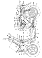
以下、本発明の実施の形態について、図1〜図8を参照しながら説明すると、先ず図1において、この自動二輪車は、低床フロア44を有するスクータ型の電動二輪車であり、後輪WRの車軸21を後部で軸支するスイングアーム22に内蔵された電動モータ23が発揮する回転動力で、前記後輪WRが回転駆動されるように構成されている。
Hereinafter, an embodiment of the present invention will be described with reference to FIGS. 1 to 8. First, in FIG. 1, the motorcycle is a scooter type electric motorcycle having a
図2において、この電動二輪車の車体フレームFは、前輪WFを軸支するフロントフォーク24ならびに該フロントフォーク24の上部に連結された操向ハンドル25を操向可能に支承するヘッドパイプ26と、該ヘッドパイプ26から後下がりに延びるダウンフレーム27と、該ダウンフレーム27の下部に連結されて後方に延びる左右一対のアンダーフレーム28…と、それらのアンダーフレーム28…の後端に一体に連なって後上がりに延びる左右一対のリヤフレーム29…とを備える。
In FIG. 2, a body frame F of this electric motorcycle includes a
前記車体フレームFにおける両リヤフレーム29…の前部に設けられたピボットプレート30…には、車体Bを左側に傾けた起立状態に保持するためのサイドスタンド31が回動可能に取付けられるとともに、前記スイングアーム22の前部が支軸32を介して揺動可能に支承され、前記両リヤフレーム29…のうち左側のリヤフレーム29の後部および前記スイングアーム22の後部間にはリヤクッションユニット33が設けられる。また前記スイングアーム22の前部には、メインスタンド34が回動可能に取付けられる。
A side stand 31 for holding the vehicle body B in an upright state inclined to the left side is rotatably attached to a
前記両アンダーフレーム28…間には、前記電動モータ23に電力を供給するためのたとえば72Vである高電圧バッテリ36を内蔵せしめたバッテリケース37が両アンダーフレーム28…で支持されるようにして配置され、前記両リヤフレーム29…間には、側面視で前記スイングアーム22の上方に配置される収納ボックス38が、両リヤフレーム29…で支持されるようにして配置され、この収納ボックス38は、開閉可能な乗車用シート39で上方から覆われる。しかも収納ボックス38の後側下部には、補機たとえばヘッドライト51、テールライト52等に低電圧たとえば12Vの電力を供給するための低電圧バッテリ40を収納するバッテリ収納部38aが下方に突出するようにして一体に形成される。
A
前記車体フレームFは、該車体フレームFとともに車体Bを構成する合成樹脂製の車体カバー41で覆われるものであり、該車体カバー41は、前記ヘッドパイプ26を前方から覆うフロントカバー42と、前記乗車用シート39に座った乗員の脚部を前方から覆うようにして前記フロントカバー42に連なるレッグシールド43と、前記乗車用シート39に座った乗員の足を載せるようにして前記レッグシールド43の下部に連なるとともに前記バッテリケース28を上方から覆う低床フロア44と、前記両アンダーフレーム28…を両側から覆うようにして前記低床フロア44の両側から垂下される左右一対のフロアサイドカバー45…と、前記両フロアサイドカバー45…の下縁間を結ぶアンダーカバー46と、前記乗車用シート39の下方を前方から覆うようにして低床フロア44の後端から立ち上がるシート下前部カバー47と、前記乗車用シート39の下方を両側から覆うようにして前記シート下前部カバー47の両側に連なる左右一対のサイドカバー48…と、前記後輪WRを上方から覆って前記両サイドカバー48…に連なるリヤカバー49とを備え、前記バッテリケース37は、車体カバー41のうち前記低床フロア44、フロアサイドカバー45…、アンダーカバー46、シート下前部カバー47およびサイドカバー48…で覆われる。
The vehicle body frame F is covered with a synthetic resin vehicle body cover 41 that forms the vehicle body B together with the vehicle body frame F. The
前記フロントカバー42の前端には、前記ヘッドパイプ26に固定されたフロントステー50で支持されるようにしてヘッドライト51が配設され、前記リヤフレーム29…にはテールライト52が取付けられる。また前記フロントカバー42の下方に配置されるフロントフェンダ53が、前記前輪WFを上方から覆うようにして前記フロントフォーク24に取付けられ、前記後輪WRを後方斜め上方から覆うリヤフェンダ54が前記リヤカバー49に連設され、前記後輪WRを前方斜め上方から覆うフェンダ55が前記スイングアーム22の前部に取付けられる。また前記操向ハンドル25の中央部はハンドルカバー56で覆われており、フロントカバー42の前方に配置されるフロントキャリア57が前記フロントステー50で支持され、前記乗車用シート39の後方かつリヤカバー49の上部には荷物を積載するための平面部58aを有する荷台58が設けられ、この荷台58の前部には、前記平面部58aよりも上方に突出したストッパ58bが、側面視で乗車用シート39の後端との間に空間Sを形成するようにして設けられる。また荷台58の上方に配置されるキャリア59が前記リヤフレーム29…に着脱可能に取付けられる。
A
前記両アンダーフレーム28…間には、前記バッテリケース37の前後方向略中央部を跨ぐクロス部材60が設けられており、低床フロア44は該クロス部材60で支持される。また前記両アンダーフレーム28…の前部間には、前記バッテリケース37の前側下部を前方から保護する前部保護部材61がその中央部をダウンフレーム27の下端に連結するようにして設けられ、前記両アンダーフレーム28…の後部間には、前記バッテリケース37の後側下部を後方から保護する後部保護部材62が設けられ、前後方向に延びる複数の下部保護部材63…が、前記バッテリケース37を下方から保護するようにして前部および後部保護部材61,62間に設けられる。
A
前記バッテリケース37の前部には、左右一対の冷却空気導入ダクト64…の下流端部が接続管65…を介して接続され、両冷却空気導入ダクト64…は、前記レッグシールド43内で前記ダウンフレーム27を両側から挟むようにして該ダウンフレーム27に沿って延びるように配置される。一方、前記ダウンフレーム27の前記ヘッドパイプ26への連結部に対応した位置で前記レッグシールド43には、前方に凹む凹部67が形成されており、該凹部67の上部を覆うリッド68がレッグシールド43に取付けられる。而してリッド68の下縁および凹部67間には空気吸入口69が形成され、前記両冷却空気導入ダクト64…の上流端は、前記空気吸入口69に通じるようにして前記レッグシールド43に接続管66…を介して接続される。
Downstream ends of a pair of left and right cooling
前記バッテリケース37の後部上面には冷却ファン70が取付けられており、この冷却ファン70の作動により、前記空気吸入口69から吸入された空気が、接続管66…、冷却空気導入管64…および接続管65…を介してバッテリケース37内に導入され、バッテリケース37内の高電圧バッテリ36が冷却され、バッテリケース37から前記冷却ファン70によって外部に排出される。
A cooling
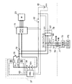
図3において、前記電動モータ23は、制御ユニットが組み込まれたパワードライブユニット(PDU)71によって駆動されるものであり、このパワードライブユニット71は、ヒューズ72および第1リレースイッチ73を介して高電圧バッテリ36のプラス側端子に接続され、第1リレースイッチ73には、第2リレースイッチ74および抵抗76から成る直列回路が並列に接続される。ところで高電圧バッテリ36および低電圧バッテリ40には、外部電源PSに接続されることで高電圧バッテリ36と同レベルの高電圧を出力し得る充電器76から充電することが可能であり、外部電源PSに接続された前記充電器76に連なる給電側接続具77を差し込み接続可能な受電側接続具78が車両側に設けられ、該受電側接続具78がDC−DCコンバータ79に接続される。
In FIG. 3, the
而して前記DC−DCコンバータ79は、受電側接続具78に連なる一対のラインL1,L2の一方L1に介設される電界効果型トランジスタ80と、充電器76からの電圧を低電圧たとえば12Vに降下せしめるようにして前記両ラインL1,L2に接続される電圧降下回路部81とを備えており、このDC−DCコンバータ79の前記両ラインL1,L2は、高電圧の充電電流を高電圧バッテリ36に供給すべく、第2リレースイッチ74および抵抗76から成る直列回路と第1リレースイッチ73との並列回路を介して高電圧バッテリ36のプラス側端子に接続されるとともに高電圧バッテリ36のマイナス側端子に接続され、前記電圧降下回路部81は、低電圧バッテリ40のプラス側端子およびマイナス側端子に接続される。
Thus, the DC-
前記パワードライブユニット71に内蔵された制御ユニットには、前記低電圧バッテリ40のプラス側端子がメインスイッチ82を介して接続されるとともに前記低電圧バッテリ40のマイナス側端子が接続される。また第1および第2リレースイッチ73,74の断・接は、低電圧バッテリ40から供給される電力によってバッテリマネイジングユニット(BMU)83から出力される制御電流により切換えられるものであり、バッテリマネイジングユニット83には、前記低電圧バッテリ40のプラス側端子が前記メインスイッチ82を介して接続されるとともに、前記低電圧バッテリ40のマイナス側端子が接続される。
A plus side terminal of the
而してメインスイッチ82がONされると、バッテリマネイジングユニット83は、先ず第2リレースイッチ74を導通状態として高電圧バッテリ36から第2リレースイッチ74、抵抗76およびヒューズ72を介してパワードライブユニット71に電流を流し、その後で、第1リレースイッチ73を導通する。これにより、パワードライブユニット71内に設けられているコンデンサへの突入電流によって第1リレースイッチ73が溶着してしまうのが防止される。
Thus, when the
なお第1リレースイッチ73、第2リレースイッチ74およびバッテリマネイジングユニット83は、高電圧バッテリ36を収納するバッテリケース37に収納される。
The first relay switch 73, the
図4〜図7を併せて参照して、収納ボックス38は、乗車用シート39で上端開口部が閉じられるようにして上端を開放した箱形に形成され、車体フレームFにおける両リヤフレーム29,29間に設けられる前後一対のクロスメンバー85,86上に支持される。またバッテリ収納部38aは、前記両クロスメンバー85,86のうち前方のクロスメンバー85よりも後方かつ車体Bの車幅方向中心から一側(この実施の形態では右側)に寄った位置で収納ボックス38の後側下部から下方に突出され、低電圧バッテリ40を収納したバッテリ収納部38aを上方から閉じる蓋板87が収納ボックス38の下部に複数たとえば一対のねじ部材88,88で締結される。
4 to 7 together, the
乗車用シート39は、底板89上にクッション材90が設けられて成り、この乗車用シート39の後部の左右一側、この実施の形態では左側に、上方に向けて凹むシート側凹部92が形成される。一方、前記収納ボックス38の後部の前記シート側凹部92に対応する部分に、上方に向けて凹むボックス側凹部93を形成するグリップ部94が前記シート側凹部92内に収容されるようにして設けられる。
The riding
また前記乗車用シート39における底板89には、乗車用シート39のスムーズな開閉を補助する左右一対のガイド板部89a…が、乗車用シート39を閉じるときに前記収納ボックス38の左右両側壁内面に沿って収納ボックス38内に挿入されるようにして設けられ、それらのガイド板部89a…には上下方向に延びるリブ89b…が突設される。
A pair of left and right
ところで前記収納ボックス38の後部上端には、後方に張り出すボックス側後フランジ部95が設けられており、前記ボックス側凹部93を形成する前記グリップ部94が、前記ボックス側後フランジ部95の一部を上方に隆起させた隆起部95aと、前記ボックス側後フランジ部95の先端から下方に延びる垂下部95bとで構成される。
By the way, a box-side
しかも前記シート側凹部92および前記ボックス側凹部93は、乗車用シート39の後面側まで回り込んで形成されており、乗車用シート39の下方を両側から覆うサイドカバー48…のうち左側のサイドカバー48には、その上端から内側に張り出すカバー側フランジ部48aが一体に設けられ、該カバー側フランジ部48aは、前記シート側凹部91および前記ボックス側凹部93を下方から覆うことになる。
In addition, the seat-
前記ボックス側後フランジ部95の中央部には開口部96が設けられており、前記乗車用シート39の後側下部には、その閉じ状態で前記開口部96に挿通されるフック(図示せず)が設けられており、開口部96に挿通されるフックに係脱可能に係合して乗車用シート39の閉鎖状態を維持し得るシートキャッチ機構97(図7参照)が、前記クロスメンバー86に取付けられた支持板98で支持される。
An
前記収納ボックス38の前端には、その上端から前方に延びるボックス側前フランジ部99が一体に設けており、このボックス側前フランジ部99の幅方向中央部に、前記乗車用シート39の前側下部がヒンジ機構100を介して回動可能に支持される。
A box-side
前記ヒンジ機構100は、前記ボックス側前フランジ部99の幅方向中央部に固定されるブラケット101に、水平な同一軸線を有する左右一対の軸103…を介して回動板102が回動可能に支持されて成るものであり、回動板102が、乗車用シート39の前部における底板89の下面に固定される。
The
しかも前記ヒンジ機構100は、乗車用シート39の前部で前方から覆われるとともに、該乗車用シート39の下方を前方から覆うシート下前部カバー47で下方から覆われる。すなわちシート下前部カバー47の上部には、乗車用シート39を図5の鎖線で示すように開いたときに、該乗車用シート39の前端が接触するのを避けるための凹部47aが後方側に凹んで設けられるとともに、前記ヒンジ機構100を下方から覆うために前記凹部47aから前上がりに延びる突片47bが一体に形成される。
In addition, the
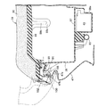
ところで左右のサイドカバー48…のうち左側のサイドカバー48において、前記乗車用シート39の下方には、給電側接続具77を接続可能な受電側接続具78を臨ませる開口部105が設けられ、該開口部105を覆うことを可能とした蓋部材106がヒンジ機構107を介してサイドカバー48に回動可能に支承される。
By the way, in the
前記左側のサイドカバー48には、前記開口部105を開口端とした大凹部108が内方側に凹むようにして形成されており、この大凹部108の内端閉塞壁108aの中央には、さらに内方に凹む矩形の小凹部109が設けられ、その小凹部109の内端閉塞壁109aに前記受電側接続具78が固定される。しかも前記内端閉塞壁108a,109aは、ともに上方に向かうにつれて内方位置となるように傾斜している。これにより受電側接続具78には、前記給電側接続具77を斜め上方から差し込むようにして接続することができ、給電側接続具77の受電側接続具78への接続作業を容易とすることができる。
The
また前記蓋部材106は、3つの頂部P1,P2,P3を有して略三角形状に形成されており、前記開口部105も蓋部材106に対応して略三角形状に形成される。しかも蓋部材106は、前記開口部105を閉鎖した状態では前記各頂部P1〜P3のうちの1つP1を下方に向けた姿勢となるようにして、前記蓋部材106が前記サイドカバー48に回動可能に支承される。
The
しかも前記蓋部材106の外観意匠面には、その蓋部材106の内側に受電側接続具78が配設されていることを示すデザインマーク110(図1参照)が施されている。
Moreover, a design mark 110 (see FIG. 1) indicating that the power receiving
図8を併せて参照して、前記蓋部材106および前記サイドカバー48間には、閉鎖維持機構111が設けられ、該閉鎖維持機構111は、前記開口部105の近傍でサイドカバー48の表面に臨んで配置される操作子である押しボタン112の操作に応じて、前記蓋部材106を閉鎖位置に維持するロック状態ならびに前記蓋部材106を開放操作することを許容するアンロック状態を切換えることが可能である。
Referring also to FIG. 8, a
この閉鎖維持機構111は、前記蓋部材106の内面側に設けられた突部106a内に収容されて前記蓋部材106にねじ部材118で締結されるフック113と、前記サイドカバー48の内面にねじ部材119で締結されるブラケット114と、該ブラケット114に支軸116を介して回動可能に支持される回動部材115と、前記支軸116を囲繞して前記ブラケット114および前記回動部材115間に設けられるねじりばね117とを備える。
The closing and maintaining
前記回動部材115は、前記支軸116から前記押しボタン112側に延びる第1腕部115aと、前記支軸116から前記フック側に延びる第2腕部115bと、第1腕部115aの先端に設けられて前記押しボタン112の内端に当接する当接板部115cと、前記フック113に係合することを可能として第2腕部115bの先端に設けられる係合爪115dとを一体に有し、前記ねじりばね117は、前記当接板部115cを押しボタン112に押しつけるとともに、前記係合爪115dをフック113に係合する方向に前記回動部材115を付勢する。
The rotating
前記押しボタン112は、その外端を前記開口部105の後方斜め上方でサイドカバー48の表面から突出させるようにしてサイドカバー48に支承されており、その内端に設けられる鍔部112aがサイドカバー48の内面に係合することでサイドカバー48からの抜け出しが阻止される。
The
而して前記押しボタン112をねじりばね117のばね力に抗して押し込み操作することにより、閉鎖維持機構111の回動部材115は係合爪115dをフック113から離脱させるように回動し、この状態で蓋部材106を開放操作することができる。また蓋部材106を閉じると、前記ねじりばね117のばね力によって係合爪115dがフック113に係合することになり、蓋部材106の閉鎖状態が維持されることになる。すなわち閉鎖維持機構111は、前記押しボタン112の非操作状態で蓋部材106を閉鎖位置に維持するロック状態ならびに前記押しボタン112の操作に応じて前記蓋部材106を開放操作することを許容するアンロック状態を切換えることになる。
Thus, by pushing the
ところで閉鎖維持機構111は、前記蓋部材106における前記各頂部P1〜P3のうち特定の頂部であるP3で前記蓋部材106およびサイドカバー48間に設けられており、特定の頂部P3の対辺部で蓋部材106がヒンジ機構107を介して前記サイドカバー48に回動可能に支承される。
By the way, the
また前記押しボタン112による閉鎖維持機構111のロック状態からアンロック状態への切換作動は、規制手段120によって規制可能であり、この規制手段120は、切換操作子である回動可能な摘まみ121の回動操作に応じて機械的に作動するように構成されており、前記摘まみ121は、前記収納ボックス38内で回動操作することを可能として収納ボックス38に配設される。
Further, the switching operation of the closing and maintaining
而して前記規制手段120は、前記収納ボックス38の外側面に固定される支持枠123で固定支持されるようにして収納ボックス38を貫通するとともに前記摘まみ121を回動可能に支承する支持筒122と、前記摘まみ121の回動操作によって回動するようにして該摘まみ121に連動、連結されるとともに前記支持筒122の外端から側方に延びる回動規制腕124とを備え、回動規制腕124に当接することでロック状態からアンロック状態に切換わる方向に回動部材115が回動することを規制するための規制突部115eが前記回動部材115に一体に設けられる。
Thus, the restricting means 120 penetrates the
すなわち規制手段120は、前記閉鎖維持機構111のロック状態からアンロック状態への切換を規制する規制状態ならびに前記閉鎖維持機構111のロック状態からアンロック状態への切換を許容する規制解除状態を切換える摘まみ121を有しており、この規制手段120のうち前記摘まみ121を除く部分が、前記収納ボックス38および前記サイドカバー48間に配置され、前記収納ボックス38の側壁に設けられて内方に凹んだ収容凹部38bに収容される。
That is, the restricting means 120 switches between a restricting state that restricts the switching of the closing and maintaining
ところで給電側接続具77に連なる充電コード125を蓋部材106の閉鎖状態で引き出すための溝126が、前記開口部105の前側上部に連なるようにしてサイドカバー48に設けられており、閉鎖状態にある前記蓋部材106および前記サイドカバー48間に挟まれる前記充電コード125と、前記蓋部材106および前記サイドカバー48の少なくとも一方との間には弾性部材127が介装されるものであり、この実施の形態では蓋部材106の内面に前記弾性部材127が固着される。
By the way, a
次にこの実施の形態の作用について説明すると、乗車用シート39の後部の左右一側に、上方に向けて凹むシート側凹部92が形成され、収納ボックス38の後部の前記シート側凹部92に対応する部分に、上方に向けて凹むボックス側凹部93を形成するグリップ部94が前記シート側凹部92内に収容されるようにして設けられるので、グリップ部94を側方から視認し易くし、グリップ部94を簡単に探すことが可能となる。また荷台58に荷物が載せられた場合にも、荷台58の前方の収納ボックス38の後部の左右一側にグリップ部94が設けられているので、荷物の多少によらず、グリップ部94をスムーズに握ることができる。これにより収納ボックス38の大型化を回避するとともに、部品点数の増加および組付け工数の増加を回避しつつ、車体を起立状態にするためのグリップ部94を確保することができる。
Next, the operation of this embodiment will be described. A seat-
また前記シート側凹部92および前記ボックス側凹部93が、前記乗車用シート39の後面側まで回り込んで形成されるので、メインスタンド34で車体Bを起立させるときに車体Bを後方側に引っ張り易くなり、車体Bを起立させる作業が容易となる。
Further, since the seat-
しかも荷物を載せる平面部58aよりも上方に突出したストッパ58bが、側面視で乗車用シート39の後端との間に空間Sを形成するようにして荷台58の前部に設けられるので、荷台58の平面部58aに荷物が載せられた状態でも乗車用シート39の後端およびストッパ58b間の空間に手を挿入して乗車用シート39の後面側まで回り込ませることができ、メインスタンド34の起立作業が容易となる。
Moreover, since the
また乗車用シート39の下方は両側からサイドカバー48…で覆われており、前記シート側凹部92および前記ボックス側凹部93を下方から覆うカバー側フランジ部48aが、前記シート側凹部92および前記ボックス側凹部93が設けられる側のサイドカバー48にその上端から内側に張り出すようにして設けられるので、シート側凹部92およびボックス側凹部93を形成することで空いた空間から車体Bの内側を見え難くすることができる。
The lower side of the riding
また乗車用シート39の前側下部が、収納ボックス38の前部上端から前方に延びるようにして前記収納ボックス38の前端に設けられるボックス側前フランジ部99にヒンジ機構100を介して回動可能に支持され、前記ヒンジ機構100が、前記乗車用シート39の前部で前方から覆われるとともに前記乗車用シート39の下方を前方から覆うシート下前部カバー47で下方から覆われるので、ヒンジ機構100を外部から視認し難くすることができ、美観の向上に寄与することができる。
Further, the front lower portion of the riding
さらに収納ボックス38の後部上端に、後方に張り出すボックス側後フランジ部95が設けられ、前記ボックス側凹部93を形成する前記グリップ部94が、前記ボックス側後フランジ部95の一部を上方に隆起させた隆起部95aと、前記ボックス側後フランジ部95の先端から下方に延びる垂下部95bとで構成されるので、ボックス側凹部93を形成したことによるグリップ部94およびボックス側後フランジ部95の剛性低下を垂下部95bによって抑えることができる。
Further, a box-side
ところで左側のサイドカバー48には、外部電源PSに充電器75を介して連なる給電側接続具77を接続可能な受電側接続具78を臨ませる開口部105が設けられ、その開口部105を覆うことを可能とした蓋部材106がヒンジ機構107を介して左側の前記サイドカバー48に回動可能に支承されており、開口部105の近傍でサイドカバー48の表面に臨んで配置される押しボタン112の非操作状態で前記蓋部材106を閉鎖位置に維持するロック状態ならびに前記押しボタン112の操作に応じて前記蓋部材106を開放操作することを許容するアンロック状態を切換える閉鎖維持機構111が、蓋部材106およびサイドカバー48間に設けられる。
By the way, the
したがって収納ボックス38を上方から覆う乗車用シート39の開閉作業を行うことを不要として、乗車用シート39を閉じ状態としたままで充電作業を行うことができる。また押しボタン112の配設位置が素早く見つけられるとともに、押しボタン112を操作するだけで蓋部材106を開放して充電作業を行うことができ、充電作業の簡素化を図ることができる。特に押しボタン112をアンロック状態にしておけば、いつでも蓋部材106を直ちに開放状態とすることができ、素早い充電が可能となり、必要に応じて押しボタン112をロック状態とすれば、蓋部材106を第三者が開放することができないようにでき、使い勝手に合わせた選択が可能となる。
Therefore, it is not necessary to perform the opening / closing operation of the riding
また略三角形状に形成される蓋部材106の3つの頂部P1〜P3のうちの1つである特定の頂部P3で蓋部材106およびサイドカバー48間に閉鎖維持機構111が設けられ、特定の頂部P3の対辺部で蓋部材106がヒンジ機構107を介してサイドカバー48に回動可能に支承されるので、外力によって生じる蓋部材106およびサイドカバー48間の隙間を小さくし、いたずら防止機能を果たすことができる。
In addition, a
また蓋部材106の外観意匠面には、その蓋部材106の内側に受電側接続具78が配設されていることを示すデザインマーク110が施されているので、充電作業を行う際に、受電側接続具78が配置されている場所を素早く探すことができ、充電作業効率の向上に寄与することができる。
In addition, since the
しかも蓋部材106の閉鎖状態では、前記各頂部P1〜P3のうちの1つであるP1を下方に向けた姿勢となるので、開口部105を閉鎖した状態では、蓋部材106に付着した雨水等を下方位置の頂部P1側に集めて水切りすることができる。
Moreover, in the closed state of the
また閉鎖状態にある前記蓋部材106と、前記サイドカバー48との間に、前記蓋部材106および前記サイドカバー48の少なくとも一方との間に弾性部材127を介在させて前記給電側接続具77に連なる充電コード125が挟まれるので、充電中に蓋部材106を閉鎖状態とすることができる。
In addition, an
また閉鎖維持機構111のロック状態からアンロック状態への切換作動が規制手段120で規制されるようにしたので、押しボタン112による閉鎖維持機構111のロック状態からアンロック状態への切換作動を規制したい場合に有効である。
In addition, since the switching operation from the locked state to the unlocked state of the closing and maintaining
しかも規制手段120の一部を構成する摘まみ121は収納ボックス38内で操作可能であるので、乗員の使い勝手に合わせた閉鎖維持機構の利用が可能となる。
In addition, since the
また規制手段120のうち摘まみ121を除く部分が収納ボックス38およびサイドカバー48間に配置されるので、規制手段120のコンパクト化を図り、規制手段120および閉鎖維持機構111を含む充電口構造をコンパクト化することができる。
Further, since the portion excluding the
さらに規制手段120が摘まみ121の回動操作によって機械的に作動するように構成されるので、コストの増大を抑えつつ、規制手段120を作動せしめる動力源を不要とすることができる。
Furthermore, since the restricting means 120 is configured to be mechanically operated by the turning operation of the
以上、本発明の実施の形態について説明したが、本発明は上記実施の形態に限定されるものではなく、特許請求の範囲に記載された本発明を逸脱することなく種々の設計変更を行うことが可能である。 Although the embodiments of the present invention have been described above, the present invention is not limited to the above-described embodiments, and various design changes can be made without departing from the present invention described in the claims. Is possible.
23・・・・電動モータ
36・・・・バッテリである高電圧バッテリ
38・・・・収納ボックス
39・・・・乗車用シート
48・・・・サイドカバー
77・・・・給電側接続具
78・・・・受電側接続具
105・・・開口部
106・・・蓋部材
107・・・ヒンジ機構
110・・・デザインマーク
111・・・閉鎖維持機構
112・・・操作子である押しボタン
120・・・規制手段
121・・・切換操作子である摘まみ
125・・・充電コード
127・・・弾性部材
P1,P2,P3・・・頂部
PS・・・・外部電源
WR・・・・後輪
23...
Claims (8)
前記サイドカバー(48)に、外部電源(PS)に連なる給電側接続具(77)を接続可能な受電側接続具(78)を臨ませる開口部(105)が設けられ、該開口部(105)を覆うことを可能とした蓋部材(106)がヒンジ機構(107)を介して前記サイドカバー(48)に回動可能に支承され、前記開口部(105)の近傍で前記サイドカバー(48)の表面に臨んで配置される操作子(112)の非操作状態で前記蓋部材(106)を閉鎖位置に維持するロック状態ならびに前記操作子(112)の操作に応じて前記蓋部材(106)を開放操作することを許容するアンロック状態を切換える閉鎖維持機構(111)が、前記蓋部材(106)および前記サイドカバー(48)間に設けられ、前記蓋部材(106)が、3つの頂部(P1〜P3)を有して略三角形状に形成されると共に、それら3つの頂部(P1〜P3)のうちの1つである特定の頂部(P3)で前記蓋部材(106)およびサイドカバー(48)間に前記閉鎖維持機構(111)が設けられ、前記特定の頂部(P3)の対辺部で前記蓋部材(106)が前記ヒンジ機構(107)を介して前記サイドカバー(48)に回動可能に支承されることを特徴とする電動二輪車。 An electric motor (23) that exerts power to drive the rear wheels (WR); a battery (36) that supplies electric power to the electric motor (23); a passenger seat (39) on which an occupant is seated; A storage box (38) disposed below the passenger seat (39), and a side cover (48) covering the storage box (38) below the riding seat (39), the battery (36) In an electric motorcycle that can be charged to
The side cover (48) is provided with an opening (105) facing the power receiving side connection tool (78) to which the power supply side connection tool (77) connected to the external power source (PS) can be connected. A lid member (106) capable of covering the side cover (48) is rotatably supported on the side cover (48) via a hinge mechanism (107), and the side cover (48) is provided in the vicinity of the opening (105). The lid member (106) is in a locked state in which the lid member (106) is maintained in a closed position when the operator (112) disposed facing the surface of the lid is not operated, and the operation member (112) is operated. ) Is provided between the lid member (106) and the side cover (48) , and the lid member (106) includes three pieces. Summit The lid member (106) and the side cover are formed at a specific top portion (P3) which is one of the three top portions (P1 to P3). (48), the closure maintaining mechanism (111) is provided, and the lid member (106) is connected to the side cover (48) via the hinge mechanism (107) at the opposite side of the specific top (P3). electric two-wheeled vehicle, characterized in that it is rotatably supported.
前記サイドカバー(48)に、外部電源(PS)に連なる給電側接続具(77)を接続可能な受電側接続具(78)を臨ませる開口部(105)が設けられ、該開口部(105)を覆うことを可能とした蓋部材(106)がヒンジ機構(107)を介して前記サイドカバー(48)に回動可能に支承され、前記開口部(105)の近傍で前記サイドカバー(48)の表面に臨んで配置される操作子(112)の非操作状態で前記蓋部材(106)を閉鎖位置に維持するロック状態ならびに前記操作子(112)の操作に応じて前記蓋部材(106)を開放操作することを許容するアンロック状態を切換える閉鎖維持機構(111)が、前記蓋部材(106)および前記サイドカバー(48)間に設けられ、閉鎖状態にある前記蓋部材(106)と、前記サイドカバー(48)との間に、前記蓋部材(106)および前記サイドカバー(48)の少なくとも一方との間に弾性部材(127)を介在させて前記給電側接続具(77)に連なる充電コード(125)が挟まれることを特徴とする電動二輪車。 An electric motor (23) that exerts power to drive the rear wheels (WR); a battery (36) that supplies electric power to the electric motor (23); a passenger seat (39) on which an occupant is seated; A storage box (38) disposed below the passenger seat (39), and a side cover (48) covering the storage box (38) below the riding seat (39), the battery (36) In an electric motorcycle that can be charged to
The side cover (48) is provided with an opening (105) facing the power receiving side connection tool (78) to which the power supply side connection tool (77) connected to the external power source (PS) can be connected. A lid member (106) capable of covering the side cover (48) is rotatably supported on the side cover (48) via a hinge mechanism (107), and the side cover (48) is provided in the vicinity of the opening (105). The lid member (106) is in a locked state in which the lid member (106) is maintained in a closed position when the operator (112) disposed facing the surface of the lid is not operated, and the operation member (112) is operated. ) is closed holding mechanism for switching the unlocked state for allowing the opening operation of the (111), provided between said lid member (106) and the side cover (48), said lid member in the closed state (106 And the side cover (48), an elastic member (127) is interposed between the lid member (106) and at least one of the side cover (48), and the power supply side connector (77). charging cord (125) is you characterized electrostatic dynamic motorcycle to be caught leading to.
前記サイドカバー(48)に、外部電源(PS)に連なる給電側接続具(77)を接続可能な受電側接続具(78)を臨ませる開口部(105)が設けられ、該開口部(105)を覆うことを可能とした蓋部材(106)がヒンジ機構(107)を介して前記サイドカバー(48)に回動可能に支承され、前記開口部(105)の近傍で前記サイドカバー(48)の表面に臨んで配置される操作子(112)の非操作状態で前記蓋部材(106)を閉鎖位置に維持するロック状態ならびに前記操作子(112)の操作に応じて前記蓋部材(106)を開放操作することを許容するアンロック状態を切換える閉鎖維持機構(111)が、前記蓋部材(106)および前記サイドカバー(48)間に設けられ、前記操作子(112)による前記閉鎖維持機構(111)のロック状態からアンロック状態への切換作動を規制する規制手段(120)を備えており、この規制手段(120)は、前記閉鎖維持機構(111)のロック状態からアンロック状態への切換を規制する規制状態ならびに前記閉鎖維持機構(111)のロック状態からアンロック状態への切換を許容する規制解除状態を切換える切換操作子(121)を有すると共に、該切換操作子(121)が前記収納ボックス(38)内で操作可能として収納ボックス(38)に配設されることを特徴とする電動二輪車。The side cover (48) is provided with an opening (105) facing the power receiving side connection tool (78) to which the power supply side connection tool (77) connected to the external power source (PS) can be connected. A lid member (106) capable of covering the side cover (48) is rotatably supported on the side cover (48) via a hinge mechanism (107), and the side cover (48) is provided in the vicinity of the opening (105). The lid member (106) is in a locked state in which the lid member (106) is maintained in a closed position when the operator (112) disposed facing the surface of the lid is not operated, and the operation member (112) is operated. ) Is closed between the lid member (106) and the side cover (48), and the closing operation mechanism (112) is used to close the closing state. The holding mechanism (111) is provided with a restricting means (120) for restricting the switching operation from the locked state to the unlocked state. The restricting means (120) is unlocked from the locked state of the closed maintaining mechanism (111). A switching operation element (121) for switching a restriction state for restricting switching to the state and a restriction release state for allowing the switching of the closed maintaining mechanism (111) from the locked state to the unlocked state. 121) An electric motorcycle characterized in that 121) is arranged in the storage box (38) so as to be operable in the storage box (38).
Priority Applications (8)
| Application Number | Priority Date | Filing Date | Title |
|---|---|---|---|
| JP2009213691A JP5254164B2 (en) | 2009-09-15 | 2009-09-15 | Electric motorcycle |
| KR1020127009362A KR101293362B1 (en) | 2009-09-15 | 2010-09-07 | Electrically driven two-wheeled vehicle |
| US13/496,132 US8662232B2 (en) | 2009-09-15 | 2010-09-07 | Electric two-wheeled motor vehicle |
| IN1766DEN2012 IN2012DN01766A (en) | 2009-09-15 | 2010-09-07 | |
| EP10817080.4A EP2479094B1 (en) | 2009-09-15 | 2010-09-07 | Electrically driven two-wheeled vehicle |
| ES10817080.4T ES2567319T3 (en) | 2009-09-15 | 2010-09-07 | Two wheel electric propulsion vehicle |
| CN201080041143.7A CN102498031B (en) | 2009-09-15 | 2010-09-07 | Electrically driven two-wheeled vehicle |
| PCT/JP2010/065323 WO2011033967A1 (en) | 2009-09-15 | 2010-09-07 | Electrically driven two-wheeled vehicle |
Applications Claiming Priority (1)
| Application Number | Priority Date | Filing Date | Title |
|---|---|---|---|
| JP2009213691A JP5254164B2 (en) | 2009-09-15 | 2009-09-15 | Electric motorcycle |
Publications (3)
| Publication Number | Publication Date |
|---|---|
| JP2011063074A JP2011063074A (en) | 2011-03-31 |
| JP2011063074A5 JP2011063074A5 (en) | 2012-07-05 |
| JP5254164B2 true JP5254164B2 (en) | 2013-08-07 |
Family
ID=43949800
Family Applications (1)
| Application Number | Title | Priority Date | Filing Date |
|---|---|---|---|
| JP2009213691A Expired - Fee Related JP5254164B2 (en) | 2009-09-15 | 2009-09-15 | Electric motorcycle |
Country Status (1)
| Country | Link |
|---|---|
| JP (1) | JP5254164B2 (en) |
Families Citing this family (8)
| Publication number | Priority date | Publication date | Assignee | Title |
|---|---|---|---|---|
| EP2662271B1 (en) | 2010-12-27 | 2017-03-08 | Kawasaki Jukogyo Kabushiki Kaisha | Electric motorcycle |
| JP5730129B2 (en) * | 2011-05-27 | 2015-06-03 | 本田技研工業株式会社 | Cowl fastening structure |
| CN104010935B (en) * | 2011-12-22 | 2016-10-12 | 雅马哈发动机株式会社 | straddle-type electric vehicle |
| EP2796351B1 (en) * | 2011-12-22 | 2021-10-06 | Yamaha Hatsudoki Kabushiki Kaisha | Saddled electric vehicle |
| EP3677466B1 (en) | 2017-08-31 | 2021-08-18 | Yamaha Hatsudoki Kabushiki Kaisha | Electric saddled vehicle |
| TWI655119B (en) * | 2018-01-31 | 2019-04-01 | 光陽工業股份有限公司 | Electric vehicle structure |
| GB201814206D0 (en) * | 2018-08-31 | 2018-10-17 | Pushme Bikes Ltd | Mobile apparatus and energy system |
| JP7119017B2 (en) * | 2020-03-13 | 2022-08-16 | 本田技研工業株式会社 | Straddle-type electric vehicle |
Family Cites Families (5)
| Publication number | Priority date | Publication date | Assignee | Title |
|---|---|---|---|---|
| JPH05105144A (en) * | 1991-10-18 | 1993-04-27 | Yamaha Motor Co Ltd | Motorcycle driven by electric motor |
| JP3172952B2 (en) * | 1991-10-18 | 2001-06-04 | ヤマハ発動機株式会社 | Electric motorcycle |
| JP3347433B2 (en) * | 1993-10-19 | 2002-11-20 | 本田技研工業株式会社 | Electric vehicle charging cord storage structure |
| JP4372564B2 (en) * | 2004-01-20 | 2009-11-25 | 本田技研工業株式会社 | Arrangement structure for unlocking operator in vehicle |
| JP5057795B2 (en) * | 2007-02-13 | 2012-10-24 | ヤマハ発動機株式会社 | Scooter type vehicle |
-
2009
- 2009-09-15 JP JP2009213691A patent/JP5254164B2/en not_active Expired - Fee Related
Also Published As
| Publication number | Publication date |
|---|---|
| JP2011063074A (en) | 2011-03-31 |
Similar Documents
| Publication | Publication Date | Title |
|---|---|---|
| WO2011033967A1 (en) | Electrically driven two-wheeled vehicle | |
| JP5254164B2 (en) | Electric motorcycle | |
| JP5342515B2 (en) | Charging port structure and saddle-ride type vehicle | |
| JP5680431B2 (en) | Motorcycle | |
| JP5266171B2 (en) | Electric vehicle | |
| JP5728591B2 (en) | Electric vehicle | |
| WO2012085977A1 (en) | Electric motorcycle | |
| JP5237230B2 (en) | Electric motorcycle | |
| WO2011033605A1 (en) | Electric two- or three-wheeled vehicle | |
| WO2013094597A1 (en) | Saddle-ridden electric vehicle | |
| JP5456623B2 (en) | Charger | |
| EP0729878B1 (en) | Seat fastening device for a bicycle | |
| JP2012162124A (en) | Electric vehicle | |
| JP2012166763A (en) | Electric vehicle | |
| CN116323299A (en) | Two-wheeled vehicle with charging portal assembly | |
| JP5461123B2 (en) | Motorcycle | |
| JP2003154984A (en) | Power assisted bicycle | |
| WO2013094651A1 (en) | Saddle-type electric vehicle | |
| JP6121391B2 (en) | Saddle riding type electric vehicle | |
| JP5493918B2 (en) | Battery attachment / detachment structure for electric motorcycles | |
| JP5767943B2 (en) | Electric vehicle | |
| JP3902911B2 (en) | bicycle |
Legal Events
| Date | Code | Title | Description |
|---|---|---|---|
| A621 | Written request for application examination |
Free format text: JAPANESE INTERMEDIATE CODE: A621 Effective date: 20111124 |
|
| A521 | Request for written amendment filed |
Free format text: JAPANESE INTERMEDIATE CODE: A523 Effective date: 20120411 |
|
| A521 | Request for written amendment filed |
Free format text: JAPANESE INTERMEDIATE CODE: A523 Effective date: 20120518 |
|
| A131 | Notification of reasons for refusal |
Free format text: JAPANESE INTERMEDIATE CODE: A131 Effective date: 20121219 |
|
| A521 | Request for written amendment filed |
Free format text: JAPANESE INTERMEDIATE CODE: A523 Effective date: 20130218 |
|
| TRDD | Decision of grant or rejection written | ||
| A01 | Written decision to grant a patent or to grant a registration (utility model) |
Free format text: JAPANESE INTERMEDIATE CODE: A01 Effective date: 20130319 |
|
| A61 | First payment of annual fees (during grant procedure) |
Free format text: JAPANESE INTERMEDIATE CODE: A61 Effective date: 20130417 |
|
| R150 | Certificate of patent or registration of utility model |
Ref document number: 5254164 Country of ref document: JP Free format text: JAPANESE INTERMEDIATE CODE: R150 Free format text: JAPANESE INTERMEDIATE CODE: R150 |
|
| FPAY | Renewal fee payment (event date is renewal date of database) |
Free format text: PAYMENT UNTIL: 20160426 Year of fee payment: 3 |
|
| LAPS | Cancellation because of no payment of annual fees |