JP5237230B2 - Electric motorcycle - Google Patents
Electric motorcycle Download PDFInfo
- Publication number
- JP5237230B2 JP5237230B2 JP2009213538A JP2009213538A JP5237230B2 JP 5237230 B2 JP5237230 B2 JP 5237230B2 JP 2009213538 A JP2009213538 A JP 2009213538A JP 2009213538 A JP2009213538 A JP 2009213538A JP 5237230 B2 JP5237230 B2 JP 5237230B2
- Authority
- JP
- Japan
- Prior art keywords
- power
- storage box
- power receiving
- electric
- battery
- Prior art date
- Legal status (The legal status is an assumption and is not a legal conclusion. Google has not performed a legal analysis and makes no representation as to the accuracy of the status listed.)
- Active
Links
Images


Classifications
-
- Y02T10/7005—
Landscapes
- Arrangement Or Mounting Of Propulsion Units For Vehicles (AREA)
Description
本発明は、後輪を駆動する動力を発揮する電動モータと、該電動モータに電力を供給するバッテリと、乗員が着座する乗車用シートと、該乗車用シートの下方に配置される収納ボックスと、前記乗車用シートの下方で前記収納ボックスを覆うサイドカバーとを備え、前記バッテリへの充電を可能とした電動二輪車に関する。 The present invention relates to an electric motor that exerts power for driving the rear wheels, a battery that supplies electric power to the electric motor, a passenger seat on which an occupant is seated, and a storage box that is disposed below the passenger seat. And a side cover that covers the storage box below the riding seat, and relates to an electric motorcycle that can charge the battery.
電動モータが発揮する駆動力で後輪を駆動して走行する電動スクータにおいて、電動モータに電力を供給するバッテリに、充電器で充電することを可能としたものが、特許文献1で既に知られている。 An electric scooter that travels by driving a rear wheel with a driving force exerted by an electric motor, which can charge a battery that supplies electric power to the electric motor with a charger, is already known from Patent Document 1. ing.
上記特許文献1で開示されたものでは、バッテリに接続される充電器が収納ボックスの下方に配置され、前記充電器に接続された受電側接続端子が前記収納ボックスの前部に設けられており、外部電源からの充電作業を行う際には収納ボックスの上方の乗車用シートを開放する必要があるので、充電作業が煩雑となるだけでなく、充電状態では乗車用シートを開放したままとしておく必要があり、乗車用シートの閉じ状態で充電作業を行い得るようにすることが望まれる。 In the device disclosed in Patent Document 1, the charger connected to the battery is disposed below the storage box, and the power receiving side connection terminal connected to the charger is provided at the front of the storage box. When carrying out charging work from an external power source, it is necessary to open the riding seat above the storage box, which not only makes the charging work complicated, but also keeps the riding seat open in the charged state. There is a need, and it is desirable to be able to perform the charging operation with the riding seat closed.
本発明は、かかる事情に鑑みてなされたものであり、バッテリへの充電時に、乗車用シートを開放することを不要として、充電作業を容易とした電動二輪車を提供することを目的とする。 The present invention has been made in view of such circumstances, and an object of the present invention is to provide an electric motorcycle that facilitates a charging operation by eliminating the need to open a riding seat when charging a battery.
上記目的を達成するために、本発明は、後輪を駆動する動力を発揮する電動モータと、該電動モータに電力を供給するバッテリと、乗員が着座する乗車用シートと、該乗車用シートの下方に配置される収納ボックスと、前記乗車用シートの下方で前記収納ボックスを覆うサイドカバーとを備え、前記バッテリへの充電を可能とした電動二輪車において、開閉可能な蓋部材で覆われる開口部が前記サイドカバーに設けられ、外部電源に連なる給電側接続具を差し込み接続可能な受電側接続具が、前記開口部に臨むようにして前記サイドカバーおよび前記収納ボックス間に固定、配置され、前記給電側接続具の前記受電側接続具に対する差し込み接続方向が、前記受電側接続具の前方もしくは後方から前記受電側接続具に近接するにつれて車幅方向内方位置となるように傾斜して設定されることを第1の特徴とする。 In order to achieve the above object, the present invention provides an electric motor that exerts power for driving a rear wheel, a battery that supplies electric power to the electric motor, a passenger seat on which an occupant is seated, and a seat for the passenger seat. An opening that is covered with an openable / closable lid member in an electric motorcycle that includes a storage box disposed below and a side cover that covers the storage box below the riding seat, and is capable of charging the battery. A power receiving side connector that is provided on the side cover and that can be connected by inserting a power feeding side connector connected to an external power source is fixed and arranged between the side cover and the storage box so as to face the opening , The vehicle width direction as the plug connection direction of the connection tool with respect to the power reception side connection tool approaches the power reception side connection tool from the front or rear of the power reception side connection tool To be set to be inclined so that the inner position you a first feature.
本発明は、第1の特徴の構成に加えて、収納位置から前方に回動して起立位置となるメインスタンドを備え、前記受電側接続具に前方から差し込み接続可能な前記給電側接続具の差し込み接続方向が、前方から前記受電側接続具に近接するにつれて車幅方向内方位置となるように傾斜して設定されることを第2の特徴とする。 In addition to the configuration of the first feature, the present invention includes a main stand that is rotated forward from a storage position to be in an upright position, and can be inserted and connected to the power receiving side connection tool from the front side. A second feature is that the insertion connection direction is set to be inclined so as to be inward in the vehicle width direction as it approaches the power receiving side connection tool from the front.
また本発明は、後輪を駆動する動力を発揮する電動モータと、該電動モータに電力を供給するバッテリと、乗員が着座する乗車用シートと、該乗車用シートの下方に配置される収納ボックスと、前記乗車用シートの下方で前記収納ボックスを覆うサイドカバーとを備え、前記バッテリへの充電を可能とした電動二輪車において、開閉可能な蓋部材で覆われる開口部が前記サイドカバーに設けられ、外部電源に連なる給電側接続具を差し込み接続可能な受電側接続具が、前記開口部に臨むようにして前記サイドカバーおよび前記収納ボックス間に固定、配置され、前記収納ボックスの側壁の一部に、前記受電側接続具の少なくとも一部を収容、配置する収容凹部が、内方側に凹んで形成されることを第3の特徴とする。The present invention also provides an electric motor that exerts power for driving the rear wheels, a battery that supplies electric power to the electric motor, a riding seat on which an occupant is seated, and a storage box that is disposed below the riding seat. And a side cover that covers the storage box below the riding seat, and in the electric motorcycle that can charge the battery, an opening that is covered with an openable / closable lid member is provided in the side cover. The power receiving side connecting device that can be plugged in and connected to the power supply side connecting device connected to the external power source is fixed and arranged between the side cover and the storage box so as to face the opening, and on a part of the side wall of the storage box, A third feature is that a receiving recess for receiving and arranging at least a part of the power receiving side connector is formed to be recessed inward.
本発明は、第1〜第3の特徴の構成のいずれかに加えて、前記蓋部材が、車両の前後方向後方に向けて操作することで開放位置となるようにして前記サイドカバーに支承され、前記蓋部材の回動軸線が後上がりに傾斜して設定されることを第4の特徴とする。 In addition to any of the configurations of the first to third features, the present invention is supported by the side cover so that the lid member is in an open position by operating toward the rear in the front-rear direction of the vehicle. The fourth feature is that the axis of rotation of the lid member is set to be inclined rearwardly.
本発明は、第1〜第4の特徴の構成のいずれかに加えて、前記サイドカバーに、その外側面から内方に凹む凹部が、前記蓋部材で閉鎖することを可能として形成され、前記開口部が前記凹部に設けられることを第5の特徴とする。 In addition to any of the configurations of the first to fourth features, the present invention is formed such that a concave portion recessed inward from the outer surface of the side cover can be closed by the lid member, that openings are provided in the recess shall be the fifth aspect.
本発明は、第1〜第5の特徴の構成のいずれかに加えて、車体フレームの一部を構成して前記収納ボックスの側方に配置されるフレーム部材に、該フレーム部材から内側に延びる取付け部を有するステーが固定され、前記取付け部に前記受電側接続具が取り付けられることを第6の特徴とする。 In addition to any of the configurations of the first to fifth features, the present invention extends from the frame member to the frame member that constitutes a part of the vehicle body frame and is disposed on the side of the storage box. A sixth feature is that a stay having an attachment portion is fixed, and the power receiving side connection tool is attached to the attachment portion.
本発明は、第1〜第6の特徴の構成のいずれかに加えて、車体を車幅方向一側に傾けた起立状態に保持するサイドスタンドを備え、前記受電側接続具および前記開口部が、前記車幅方向で前記サイドスタンドが配置される側で前記収納ボックスの側方に配置されることを第7の特徴とする。 In addition to any of the configurations of the first to sixth features, the present invention includes a side stand that holds the vehicle body in an upright state inclined to one side in the vehicle width direction, and the power receiving side connector and the opening are A seventh feature is that the side stand is disposed on the side of the storage box in the vehicle width direction.
さらに本発明は、第1〜第7の特徴の構成のいずれかに加えて、前記外部電源に充電器を介して連なる前記給電側接続具を接続可能な前記受電側接続具が、前記収納ボックスの後方に配置されるDC−DCコンバータを介して前記バッテリに接続されることを第8の特徴とする。 Furthermore, the present invention provides the power receiving side connector capable of connecting the power supply side connector connected to the external power source via a charger, in addition to any of the first to seventh features. The eighth feature is that the battery is connected to the battery via a DC-DC converter arranged behind the battery.
なお実施の形態のリヤフレーム29が本発明のフレーム部材に対応し、実施の形態の高電圧バッテリ36が本発明のバッテリに対応し、実施の形態の開口部118が本発明の開口部に対応し、実施の形態の凹部119が本発明の凹部に対応し、実施の形態の蓋部材120が本発明の蓋部材に対応する。
The
本発明によれば、外部電源に連なる給電側接続具を差し込み接続可能な受電側接続具が、サイドカバーに設けられた開口部に臨むようにして、サイドカバーおよび収納ボックス間に固定、配置されるので、収納ボックスを上方から覆う乗車用シートの開閉作業を行うことを不要として、乗車用シートを閉じ状態としたままで充電作業を行うことができ、充電作業が容易となり、利便性が向上する。 According to the onset bright, the power receiving side connector connectable plug the power supply side connector communicating with the external power supply, so as to face the opening provided in the side cover, fixed between the side cover and housing box are arranged Therefore, it is not necessary to perform the opening / closing operation of the riding seat that covers the storage box from above, and the charging operation can be performed while the riding seat is in the closed state, which facilitates the charging operation and improves convenience. .
また特に第1の特徴によれば、給電側接続具の受電側接続具に対する差し込み接続方向が、車両の前方もしくは後方から受電側接続具に近接するにつれて車幅方向内方位置となるように傾斜した方向となっており、サイドカバーおよび収納ボックス間に受電側接続具を配置しても、収納ボックスの容積を充分に確保することができる。 In particular , according to the first feature, the insertion connection direction of the power supply side connection tool to the power reception side connection tool is inclined so as to become an inward position in the vehicle width direction as it approaches the power reception side connection tool from the front or rear of the vehicle. Thus, even if the power receiving side connector is arranged between the side cover and the storage box, the capacity of the storage box can be sufficiently secured.
また特に第2の特徴によれば、給電側接続具を受電側接続具に差し込み接続する際に、メインスタンドの回動支点にかかる力は、メインスタンドを起立位置側に保持する方向となり、給電側接続具の受電側接続具への差し込み接続に応じてメインスタンドが収納位置側に不所望に回動することはない。 In particular , according to the second feature, when the power supply side connection tool is inserted and connected to the power reception side connection tool, the force applied to the rotation fulcrum of the main stand is in a direction to hold the main stand on the standing position side. The main stand does not undesirably rotate to the storage position side in accordance with the insertion connection of the side connection tool to the power receiving side connection tool.
また特に第3の特徴によれば、収納ボックスの側壁の一部に形成された収容凹部に受電側接続具の少なくとも一部を収容、配置することにより、収納ボックスの側壁のうち必要な部分だけを凹ませて、受電側接続具がサイドカバーおよび収納ボックス間に配置されることによる収納ボックスの容積減少を小さく抑えることができる。In particular, according to the third feature, only at least a necessary portion of the side wall of the storage box can be obtained by storing and arranging at least a part of the power receiving side connection tool in the storage recess formed in a part of the side wall of the storage box. The volume reduction of the storage box due to the power receiving side connector being disposed between the side cover and the storage box can be kept small.
また特に第4の特徴によれば、蓋部材は、後上がりに傾斜した回動軸線まわりに後方に向けて操作することで開放位置となり、開放状態で蓋部材は後下がりに傾斜した姿勢となっているので、蓋部材を開放した状態での充電時に、風の作用等によって蓋部材が閉じ側に回動することを極力回避することができる。 Further, in particular , according to the fourth feature, the lid member is opened to the rear by operating backward about the rotation axis inclined upward, and the lid member is inclined downward in the opened state. Therefore, when charging with the lid member opened, it is possible to avoid as much as possible that the lid member rotates to the closed side by the action of wind or the like.
また特に第5の特徴によれば、サイドカバーに形成されるとともに蓋部材で閉じられる得る凹部に、受電側接続具が臨む開口部が設けられるので、凹部を形成する部分を補強リブとして機能させてサイドカバーの強度向上を図ることが可能となるとともに、サイドカバーの内方を、開口部以外の部分では凹部で覆うので、受電側接続具を探し易くすることができるとともに、凹部を開放した状態でサイドカバーの内方に小物を落とし難くすることができる。 Further, in particular , according to the fifth feature, since the opening that the power receiving side connection tool faces is provided in the recess that is formed on the side cover and can be closed by the lid member, the portion that forms the recess functions as a reinforcing rib. It is possible to improve the strength of the side cover, and the inside of the side cover is covered with a recess in the portion other than the opening, so that it is easy to find the power receiving side connector and the recess is opened. Ru can be difficult to drop the accessories to the inside of the side cover in the state.
また特に第6の特徴によれば、収納ボックスの側方に配置されるフレーム部材に固定されるステーに、フレーム部材から内側に延びる取付け部が設けられ、その取付け部に受電側接続具が取り付けられるので、受電側接続具がフレーム部材から外側方にはみ出さないようにして、サイドカバーのフレーム部材への取付けを容易とすることができる。 In particular , according to the sixth feature, the stay fixed to the frame member disposed on the side of the storage box is provided with an attachment portion extending inward from the frame member, and the power receiving side connection tool is attached to the attachment portion. Therefore, it is possible to facilitate the attachment of the side cover to the frame member so that the power receiving side connector does not protrude outward from the frame member.
また特に第7の特徴によれば、車体を車幅方向一側に傾けた起立状態に保持するサイドスタンドが配置される側で、前記収納ボックスの側方に受電側接続具および開口部配置されるので、サイドスタンドを起立させた駐車状態での充電作業性が向上する。 In particular , according to the seventh feature, the power receiving side connector and the opening are arranged on the side of the storage box on the side where the side stand that holds the vehicle body in an upright state inclined to one side in the vehicle width direction is arranged. Therefore, the charge workability in the parking state where the side stand is raised is improved.
また特に第8の特徴によれば、外部電源に充電器を介して連なる給電側接続具を接続可能な受電側接続具が、収納ボックスの後方に配置されるDC−DCコンバータを介してバッテリに接続されるので、受電側接続端子側へのバッテリからの逆流が生じ難くなる。 In particular , according to the eighth feature, the power receiving side connecting device that can be connected to the external power source via the charger is connected to the battery via the DC-DC converter disposed at the rear of the storage box. Since it is connected, the backflow from the battery to the power receiving side connection terminal side hardly occurs.
以下、本発明の実施の形態について、図1〜図14を参照しながら説明すると、先ず図1において、この電動二輪車は、低床フロア44を有するスクータ型の電動二輪車であり、駆動輪である後輪WRの車軸21を後部で軸支するスイングアーム22に内蔵された電動モータ23が発揮する回転動力で、前記後輪WRが回転駆動されるように構成される。
DETAILED DESCRIPTION OF THE PREFERRED EMBODIMENTS Hereinafter, embodiments of the present invention will be described with reference to FIGS. 1 to 14. First, in FIG. 1, the electric motorcycle is a scooter type electric motorcycle having a
図2において、この電動二輪車の車体フレームFは、前輪WFを軸支するフロントフォーク24ならびに該フロントフォーク24の上部に連結された操向ハンドル25を操向可能に支承するヘッドパイプ26と、該ヘッドパイプ26から後下がりに延びるダウンフレーム27と、該ダウンフレーム27の下部に連結されて後方に延びる左右一対のアンダーフレーム28…と、それらのアンダーフレーム28…の後端に一体に連なって後上がりに延びる左右一対のリヤフレーム29…とを備える。
In FIG. 2, a body frame F of this electric motorcycle includes a
前記車体フレームFにおける両リヤフレーム29…の前部に設けられたピボットプレート30…には、車体Bを左側に傾けた起立状態に保持するためのサイドスタンド31が回動可能に取付けられるとともに、前記スイングアーム22の前部が支軸32を介して揺動可能に支承され、前記両リヤフレーム29…のうち左側のリヤフレーム29の後部および前記スイングアーム22の後部間にはリヤクッションユニット33が設けられる。また前記スイングアーム22の前部にはメインスタンド34が回動可能に取付けられる。
A side stand 31 for holding the vehicle body B in an upright state inclined to the left side is rotatably attached to a
前記両アンダーフレーム28…間には、前記電動モータ23に電力を供給するためのたとえば72Vである高電圧バッテリ36を内蔵せしめたバッテリケース37が両アンダーフレーム28…で支持されるようにして配置され、前記両リヤフレーム29…間には、側面視で前記スイングアーム22の上方に配置される収納ボックス38が、両リヤフレーム29…で支持されるようにして配置され、この収納ボックス38は、開閉可能な乗車用シート39で上方から覆われる。しかも収納ボックス38の後側下部には、補機たとえば前照灯51、尾灯52および制御ユニット(図示せず)とに低電圧たとえば12Vの電力を供給するための低電圧バッテリ40を収納するバッテリ収納部38aが下方に突出するようにして一体に形成される。
A
前記車体フレームFは、該車体フレームFとともに車体Bを構成する合成樹脂製の車体カバー41で覆われるものであり、該車体カバー41は、前記ヘッドパイプ26を前方から覆うフロントカバー42と、前記乗車用シート39に座った乗員の脚部を前方から覆うようにして前記フロントカバー42に連なるレッグシールド43と、前記乗車用シート39に座った乗員の足を載せるようにして前記レッグシールド43の下部に連なるとともに前記バッテリケース37を上方から覆う低床フロア44と、前記両アンダーフレーム28…を両側から覆うようにして前記低床フロア44の両側から垂下される左右一対のフロアサイドカバー45…と、前記両フロアサイドカバー45…の下縁間を結ぶアンダーカバー46と、前記乗車用シート39の下方を前方から覆うようにして低床フロア44の後端から立ち上がるシート下前部カバー47と、前記乗車用シート39の下方を両側から覆うようにして前記シート下前部カバー47の両側に連なる左右一対のサイドカバー48…と、前記後輪WRを上方から覆って前記両サイドカバー48…に連なるリヤカバー49とを備え、前記バッテリケース37は、車体カバー41のうち前記低床フロア44、フロアサイドカバー45…、アンダーカバー46、シート下前部カバー47およびサイドカバー48…で覆われる。
The vehicle body frame F is covered with a synthetic resin vehicle body cover 41 that forms the vehicle body B together with the vehicle body frame F. The
前記フロントカバー42の前端には、前記ヘッドパイプ26に固定されたステー50で支持されるようにして前照灯51が配設され、前記リヤフレーム29…には尾灯52が取付けられる。また前記フロントフォーク24には、前輪WFを上方から覆うフロントフェンダ53が取付けられ、前記後輪WRを後方斜め上方から覆うリヤフェンダ54が前記リヤカバー49に連設され、前記後輪WRを前方斜め上方から覆うフェンダ55が前記スイングアーム22の前部に取付けられる。また前記操向ハンドル25の中央部はハンドルカバー56で覆われており、フロントカバー42の前方に配置されるフロントキャリア57が前記ステー50で支持され、前記乗車用シート39の後方かつリヤカバー49の上方には、前記リヤフレーム29…で支持されるようにしてリヤキャリア58が配置される。
A
図3において、前記電動モータ23は、制御ユニットが組み込まれたパワードライブユニット(PDU)61によって駆動されるものであり、このパワードライブユニット61は、ヒューズ62および第1リレースイッチ63を介して高電圧バッテリ36のプラス側端子に接続され、第1リレースイッチ63には、第2リレースイッチ64および抵抗76から成る直列回路が並列に接続される。ところで高電圧バッテリ36および低電圧バッテリ40には、外部電源PSに接続されることで高電圧バッテリ36と同レベルの高電圧を出力し得る充電器65から充電することが可能であり、外部電源PSに接続された前記充電器65に連なる給電側接続具66を差し込み接続可能な受電側接続具67が車両側に設けられ、該受電側接続具67がDC−DCコンバータ68に接続される。
In FIG. 3, the
而して前記DC−DCコンバータ68は、受電側接続具67に連なる一対のラインL1,L2の一方L1に介設される電界効果型トランジスタ69と、充電器65からの電圧を低電圧たとえば12Vに降下せしめるようにして前記両ラインL1,L2に接続される電圧降下回路部70とを備えており、このDC−DCコンバータ68の前記両ラインL1,L2は、高電圧の充電電流を高電圧バッテリ36に供給すべく、第2リレースイッチ64および抵抗76から成る直列回路と第1リレースイッチ63との並列回路を介して高電圧バッテリ36のプラス側端子に接続されるとともに高電圧バッテリ36のマイナス側端子に接続され、前記電圧降下回路部70は、低電圧バッテリ40のプラス側端子およびマイナス側端子に接続される。
Thus, the DC-
前記パワードライブユニット61に内蔵された制御ユニットには、前記低電圧バッテリ40のプラス側端子がメインスイッチ72を介して接続されるとともに前記低電圧バッテリ40のマイナス側端子が接続される。また第1および第2リレースイッチ63,64の断・接は、低電圧バッテリ40から供給される電力によってバッテリマネイジングユニット(BMU)73から出力される制御電流により切換えられるものであり、バッテリマネイジングユニット73には、前記低電圧バッテリ40のプラス側端子が前記メインスイッチ72およびコネクタ71を介して接続されるとともに、前記低電圧バッテリ40のマイナス側端子が接続される。
A positive side terminal of the
而してメインスイッチ72がONされると、バッテリマネイジングユニット73は、先ず第2リレースイッチ64を導通状態として高電圧バッテリ36から第2リレースイッチ64、抵抗76およびヒューズ62を介してパワードライブユニット61に電流を流し、その後で、第1リレースイッチ63を導通する。これにより、パワードライブユニット61内に設けられているコンデンサへの突入電流によって第1リレースイッチ63が溶着してしまうのが防止される。
Thus, when the
ところで高電圧バッテリ36およびパワードライブユニット61間、ならびに高電圧バッテリ36およびDC−DCコンバータ68間の回路は、高電圧バッテリ36に連なる高電力系の回路(太実線で示す回路)74を構成し、低電圧バッテリ40とパワードライブユニット61、バッテリマネイジングユニット73およびDC−DCコンバータ68との間の回路は低電圧バッテリ40に連なる低電力系の回路(細実線で示す回路)75を構成し、高電力系の回路74に、第1リレースイッチ63、第2リレースイッチ64、ヒューズ62および抵抗76が介設され、低電力系の回路75に、コネクタ71およびメインスイッチ72が介設されることになる。
By the way, the circuit between the
なお第1リレースイッチ63、第2リレースイッチ64およびバッテリマネイジングユニット73は、高電圧バッテリ36を収納するバッテリケース37に収納される。
The
図4および図5を併せて参照して、前記バッテリケース37は、上方に開いた箱形の下部ケース78と、下方に開いた箱形の上部ケース79とが複数のねじ部材80,80…で相互に締結されて成るものであり、下部ケース半体78の両側上部に固着されて側方に張り出す複数の支持板81,81…が、車体フレームFにおける両アンダーフレーム28…上にボルト82,82…と、アンダーフレーム28…に溶着されたウエルドナット83,83…とによって締結されることで、バッテリケース37が両アンダーフレーム28…に支持される。
4 and 5 together, the
前記両アンダーフレーム28…間には、前記バッテリケース37の前後方向略中央部を跨ぐクロス部材84が設けられており、低床フロア44は該クロス部材84で支持される。また前記両アンダーフレーム28…の前部間には、前記バッテリケース37の前側下部を前方から保護する前部保護部材85がその中央部をダウンフレーム27の下端に連結するようにして設けられ、前記両アンダーフレーム28…の後部間には、前記バッテリケース37の後側下部を後方から保護する後部保護部材86が設けられ、前後方向に延びる複数の下部保護部材87,87…が、前記バッテリケース37を下方から保護するようにして前部および後部保護部材85,86間に設けられる。
A
図6〜図8を併せて参照して、前記バッテリケース37における下部ケース78の前部には、左右一対の冷却空気導入ダクト88…の下流端部が接続管77…を介して接続される。ところで前記レッグシールド43は、前記ヘッドパイプ26の後部に固着されたステー103にボルト93で支持されており、このレッグシールド43内で前記ダウンフレーム27を両側から挟む両冷却空気導入ダクト88…は、該ダウンフレーム27に沿って延びるように配置される。一方、前記ダウンフレーム27の前記ヘッドパイプ26への連結部に対応した位置で前記レッグシールド43には、車両後方に向けて開口する左右一対の開口部90,90が設けられており、前記両冷却空気導入ダクト88…の上流端部は、前記開口部90…にそれぞれ通じるようにして前記レッグシールド43に接続管89…を介して接続される。
Referring to FIGS. 6 to 8, downstream ends of a pair of left and right cooling
ところで前記レッグシールド43には、その後面から前方に凹む凹部91が形成されており、前記両開口部90…は前記凹部91の上部に設けられる。しかも前記両開口部90…間の中央部で前記凹部91には、第1ボス92が後方に向かって突出するようにして一体に突設される。
By the way, the
また前記レッグシールド43には、前記両開口部90…を覆うリッド94が複数のねじ部材95,95…によって取付けられる。而して前記両開口部90…を囲む仮想長方形の各角部に対応する位置で前記凹部91には円筒状の第2ボス96,96…が一体に突設されており、それらの第2ボス96,96…に内面を当接せしめるリッド94が、該リッド94に挿通されて第2ボス96,96…に螺合される前記ねじ部材95,95…によってレッグシールド43に締結される。
Further, a
前記リッド94の下縁と、前記凹部91の下部との間には、前記両開口部90…に通じる空気導入口97が形成される。また前記凹部91の上下に間隔をあけた複数箇所たとえば2箇所には、車幅方向に長く延びて後方に突出する第1の突起98,99が前記リッド94との間に空気を流通させる隙間を形成するようにして突設され、前記リッド94の内面の上下に間隔をあけた複数箇所たとえば2箇所には、車幅方向に長く延びて前方に突出する第2の突起100,101が前記凹部91との間に空気を流通させる隙間を形成するようにして突設される。しかも2つずつの第1の突起98,99および第2の突起100,101は、上下方向で交互に配置される。
Between the lower edge of the
しかも前記レッグシールド43およびリッド94間には、前記空気導入口97および前記両開口部90…間に介在するようにしてスポンジ状の濾過部材104が挟持されており、この濾過部材104は前記第1ボス92が挿通されることによって位置決めされる。
In addition, a sponge-
ところで図1で示すように、前輪WFの車軸102はレッグシールド43よりも前方に配置されるものであり、前記両開口部90…の少なくとも一部、この実施の形態では前記両開口部90…の全部が前記前輪WFの上端よりも側面視で上方に配置される。
As shown in FIG. 1, the
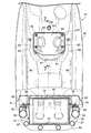
図9を併せて参照して、前記バッテリケース37内には、該バッテリケース37の後側上面、この実施の形態ではバッテリケース37の一部を構成する上部ケース79がその後部に備える立ち上がり部79aの上面に取付けられる冷却ファン105の作動によって冷却空気が導入されるものであり、吸入側を前記バッテリケース37の立ち上がり部79aに接続するとともに吐出口106を前記バッテリケース37の幅方向一側(この実施の形態では左側)に向けて開口せしめた前記冷却ファン105は、前記バッテリケース37の幅方向中心C(図9参照)から他側(この実施の形態では右側)にオフセットした位置で、前記立ち上がり部79aの上面に取付けられる。
Referring also to FIG. 9, in the
また前記立ち上がり部79aには、前記高電力系の回路74に介設される第1および第2リレースイッチ63,64が収容されるものであり、第1および第2リレースイッチ63,64は、図2で示すように、側面視で前記高電圧バッテリ36および前記低電圧バッテリ40間に配置されることになる。
The rising
ところで前記後輪WRを駆動する電動モータ23が後部に収容される前記スイングアーム22の前部には、前記後輪WRの前方に配置されるパワードライブユニット61が設けられる。而してバッテリケース37の後部内に収容される第1および第2リレースイッチ63,64は、側面視で、前記高電圧バッテリ36、前記低電圧バッテリ40および前記パワードライブユニット61によって囲まれる領域に配置されることになる。またDC−DCコンバータ68は、両リヤフレーム29…間を連結して収納ボックス38の後部を支持するクロスメンバー107(図4参照)で支持されるようにして、収納ボックス38の後方に配置される。
Incidentally, a
また前記高電力系の回路74に介設されるヒューズ62は、前記バッテリケース37の一部を構成する下部ケース78に設けられて前記立ち上がり部79aを後方から覆うリレーボード108に支持されるとともに、前記立ち上がり部79aおよびリレーボード108間に収容され、前記ヒューズ62を上方から覆う蓋部材109が複数のねじ部材110…で前記上部ケース79の立ち上がり部79aに締結される。しかも前記蓋部材109は、平面視でバッテリケース37の幅方向中心Cから一側(この実施の形態では左側)にオフセットして配置されることになる。
The
前記低電力系の回路75に介設されるコネクタ71は、低電圧バッテリ40に連なる低電力系の回路75の一部を構成する電線の導通・遮断を手動操作によって切り換えることが可能であり、前記バッテリケース37の立ち上がり部79aおよびリレーボード108間に収容されるヒューズ62への接触は、接触防止手段111の働きによって、コネクタ71で前記低電力系の回路75を遮断した状態でのみ許容される。
The
前記接触防止手段111は、前記バッテリケース37の立ち上がり部79aおよびリレーボード108間に収容された前記ヒューズ62を覆う蓋部材109の開放を前記コネクタ71で低電力系の回路75を遮断した状態でのみ許容するように構成されるものであり、前記コネクタ71が、前記蓋部材109を前記上部ケース79の立ち上がり部79aに締結する複数の前記ねじ部材110…の少なくとも1つを前記蓋部材109の開き側から覆うように配置されて成る。すなわち前記蓋部材109にその開き側から対向する位置に配置される前記コネクタ71が、その手動遮断時に前記蓋部材109の開放を許容するようにして配置されることになる。
The contact prevention means 111 is in a state where the
図10において、前記コネクタ71は、相互に分離可能とした一対のコネクタ半体112,113から成るものであり、両コネクタ半体112,113の一方112が、前記蓋部材109に設けられる保持部109aに挿通、保持され、そのコネクタ半体112に結合されるコネクタ半体113が、蓋部材109を上部ケース79の立ち上がり部79aに締結する複数の前記ねじ部材110…の1つの上方に配置される。
In FIG. 10, the
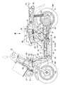
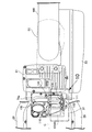
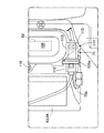
図11〜図14において、前記収納ボックス38は、前記両リヤフレーム29…間にわたって設けられる前記クロスメンバー107と、該クロスメンバー107よりも前方で両リヤフレーム29…間に設けられるクロスメンバー114とで支持されており、車幅方向において前記サイドスタンド31が配置される側で前記収納ボックス38の側方には、前記充電器65に連なる給電側接続具66を差し込み接続可能とした受電側接続具67が配置される。而して車体フレームFの一部を構成して前記収納ボックス38の側方に配置される左右一対のリヤフレーム29…のうち左側のリヤフレーム29には、該リヤフレーム29から内側に延びる取付け部116aを有するステー116が固定され、前記取付け部116aに前記受電側接続具67が取り付けられる。
11 to 14, the
しかも前記受電側接続具67への前記給電側接続具66の差し込み接続方向117は、前記受電側接続具67の前方もしくは後方から前記受電側接続具67に近接するにつれて車幅方向内方位置となるように傾斜して設定されるものであり、この実施の形態では、前記受電側接続具67に前方から差し込み接続可能な前記給電側接続具66の差し込み接続方向117が、前方から前記受電側接続具67に近接するにつれて車幅方向内方位置となるように傾斜して設定され、この差し込み接続方向117は、収納位置から前方に回動して起立位置となるメインスタンド34の回動支点に、給電側接続具66を受電側接続具67に差し込み接続する際にかかる力が、メインスタンド34を起立位置側に保持する方向すなわち後方に向かう方向である。
Moreover, the
前記収納ボックス38の左側のサイドカバー48には、前記受電側接続具67を臨ませる開口部118が設けられるものであり、この開口部118は、前記サイドカバー48の外側面から内方に凹むようにして前記サイドカバー48に形成される凹部119に設けられる。
The
しかも前記開口部118および凹部119は開閉可能として前記サイドカバー48に取付けられる蓋部材120で覆われるものであり、この蓋部材120は、車両の前後方向後方に向けて操作することで開放位置となるようにして前記サイドカバー48にヒンジ機構121を介して支承されており、その蓋部材120の回動軸線CL(図1参照)は後上がりに傾斜して設定される。
Moreover, the
しかも前記凹部119の前部には、前記受電側接続具67に給電側接続具66を接続して状態で前記蓋部材120を閉じたときに前記給電側接続具66に連なる導線122をサイドカバー48および蓋部材120間から外部に導出するための導出溝123が設けられており、前記導線122および前記蓋部材120間に介装せしめるための弾性部材124が前記蓋部材120の内面に貼着される。
In addition, a
また前記収納ボックス38の左側壁外面には、前記受電側接続具67の少なくとも一部(この実施の形態では一部)を収容、配置する収容凹部38bが内方側に凹んで形成される。
Further, on the outer surface of the left side wall of the
次にこの実施の形態の作用について説明すると、後輪WRを駆動する動力を発揮する電動モータ23に高電圧の電力を供給する高電圧バッテリ36がバッテリケース37に収容されており、バッテリケース37内には冷却ファン105の作動によって冷却空気導入ダクト88…から冷却空気が導入されるのであるが、車両後方に向けて開口する開口部90…がレッグシールド43に設けられており、冷却空気導入ダクト88…の上流端が開口部90…に連なるようにしてレッグシールド43に接続されるので、比較的清浄である空気がバッテリケース37内に導かれ易くなり、風路に塵埃等が溜まり難くなり、長期使用による風路抵抗の増大を抑制することができる。
Next, the operation of this embodiment will be described. A
またレッグシールド43にその後面から前方に凹むとともに上部には開口部90…が設けられる凹部91が形成され、開口部90…を覆ってレッグシールド43に取付けられるリッド94の下縁と、凹部91の下部との間に、開口部90…に通じる空気導入口97が形成されるので、雨水が開口部90…から冷却空気導入ダクト88…内に浸入し難くなり、雨水によって塵埃が冷却空気導入ダクト88…の内面に固着することによる風路抵抗の増大を抑制することができる。
Further, the
また前記凹部91には、車幅方向に長く延びて後方に突出する第1の突起98,99がリッド94との間に空気を流通させる隙間を形成するようにして突設され、リッド94の内面には、車幅方向に長く延びて前方に突出する第2の突起100,101が凹部91との間に空気を流通させる隙間を形成するようにして突設されるので、第1および第2の突起98,99;100,101で雨水の水切りが可能となり、雨水の冷却空気導入ダクト88…内への浸入をより効果的に防止することができ、第1の突起98,99が補強リブの機能を果たすことでレッグシールド43の剛性向上が可能となり、第2の突起100,101が補強リブの機能を果たすことでリッド94の剛性向上が可能となる。しかも複数たとえば2つずつの第1および第2の突起98,99;100,101が、上下方向で交互に配置されるので、雨水の冷却空気導入ダクト88…内への浸入をさらに効果的に防止することができる。
Further, the
しかもレッグシールド43およびリッド94間に、空気導入口97および両開口部90…間に介在するようにしてスポンジ状の濾過部材104が挟持されるので、バッテリケース37内に導かれる空気をより清浄化し、長期使用による風路抵抗の増大をより効果的に抑制することができる。
Moreover, since the sponge-
また前輪WFの車軸102がレッグシールド43よりも前方に配置され、開口部90…の少なくとも一部が、前輪WFの上端よりも側面視で上方に配置されるので、路面から開口部90…までの距離を比較的大きくし、路面から巻き上げられる塵埃が開口部90…に侵入し難くすることができる。
Further, since the
ところでヘッドパイプ26から後下がりに延びるダウンフレーム27の下部から後方に延びる左右一対のアンダーフレーム28…間にバッテリケース37が配置され、冷却空気導入ダクト88…がレッグシールド43内でダウンフレーム27に沿って延びるように配置されるので、レッグシールド43内に冷却空気導入ダクト88…が収容される構成であってもレッグシールド43をコンパクトにすることができ、レッグシールド43の大型化を抑制することができる。また左右一対の冷却空気導入ダクト88…がダウンフレーム27を両側から挟むように配置されるので、バッテリケース37内に導入する冷却空気量を充分に確保しつつ冷却空気導入ダクト88…の大型化を回避することができる。
By the way, a
さらに車体カバー41で覆われるバッテリケース37に吸入側を接続するとともにその吐出口106をバッテリケース37の幅方向一側に向けて開口せしめられた冷却ファン105が、バッテリケース37の幅方向中心Cから他側にオフセットした位置でバッテリケース37の後側上面に取付けられるので、冷却ファン105から排出された空気が車体カバー41にあたって跳ね返ってくることによる風路抵抗を減少させることが可能となる。
Further, the cooling
また高電圧バッテリ36に連なる高電力系の回路74には、ヒューズ62と、低電圧バッテリ40に連なる低電力系の回路75からの電力供給によって高電力系の回路74の断・接を切換可能であるとともに低電力系の回路75の遮断時には高電力系の回路74を遮断する第1および第2リレースイッチ63,64とが介設され、前記低電力系の回路75には、該低電力系の回路75の断・接を手動操作によって切換え得るコネクタ71が介設されており、前記ヒューズ62にメンテナンスのために接触することは、バッテリケース37の立ち上がり部79aおよびリレーボード108間に収容された前記ヒューズ62を覆う蓋部材109の開放を、前記コネクタ71によって前記低電力系の回路75が遮断されている状態でのみ許容するように構成される接触防止手段111の働きにより、前記コネクタ71によって低電力系の回路75が遮断されている状態でのみ許容される。
The
したがって低電力系の回路75が遮断されている状態でのみヒューズ62への接触が許容され、その状態では、第1および第2リレースイッチ63,64が遮断状態にあって高電力系の回路74が遮断されているので、ヒューズ62のメンテナンスを行う時にはコネクタ71による低電力系の回路75の遮断が必要となり、高電力系のヒューズ62のメンテナンス時の作業手順が守り易くなる。
Therefore, the contact with the
しかも高電圧バッテリ36を収容するバッテリケース37における上部ケース79の立ち上がり部79aに、複数のねじ部材110…で蓋部材109が締結されており、コネクタ71は、蓋部材109にその開き側から対向する位置にその手動遮断時に蓋部材109の開放を許容するようにして配置されており、接触防止手段111は、コネクタ71が、前記低電力系の回路75の一部を構成する電線の導通・遮断を手動操作によって切り換えることを可能として、複数の前記ねじ部材110…の少なくとも1つを前記蓋部材109の開き側から覆うように配置されて成るので、コネクタ71による手動遮断時に蓋部材109の開放を許容するようにすることで、接触防止手段111を簡素な構造で構成することができる。
In addition, a
またヒューズ62および蓋部材109が、平面視でバッテリケース37の幅方向中心から一側にオフセットした位置に配置されるので、車体Bの幅方向一側からのメンテナンス作業を行い易くなる。
In addition, since the
また高電圧バッテリ36が左右一対の前記アンダーフレーム28…間に配置され、低電圧バッテリ40が左右一対のリヤフレーム29…間に配置されるので、高電圧バッテリ36および低電圧バッテリ40の外部からの保護が可能であり、第1および第2リレースイッチ63,64が、側面視で前記高電圧バッテリ36および前記低電圧バッテリ40間に配置されるので、リレー配線のコンパクト化が可能となる。
Further, since the
またスイングアーム22の前部が、車体フレームFにおける両リヤフレーム29…の前部に設けられたピボットプレート30…に揺動自在に支承され、電動モータ23と、該電動モータ23を駆動するようにして後輪WRの前方に配置されるパワードライブユニット61とが前記スイングアーム22に設けられ、第1および第2リレースイッチ63,64が、側面視で前記高電圧バッテリ36、前記低電圧バッテリ40および前記パワードライブユニット61によって囲まれる領域に配置されるので、第1および第2リレースイッチ63,64の周囲に高圧系の電装部品を配置して、高圧系の配線をコンパクト化することができる。
Further, the front portion of the
ところで乗員が着座する乗車用シート39の下方には収納ボックス38が配置され、乗車用シート39の下方で収納ボックス38を覆うサイドカバー48には、開閉可能な蓋部材120で覆われる開口部118が設けられ、充電器65に連なる給電側接続具66を差し込み接続可能な受電側接続具67が、開口部118に臨むようにしてサイドカバー48および収納ボックス38間に固定、配置されるので、収納ボックス38を上方から覆う乗車用シート39の開閉作業を行うことを不要として、乗車用シート39を閉じ状態としたままで充電作業を行うことができ、充電作業が容易となり、利便性が向上する。
By the way, a
また給電側接続具66の受電側接続具67に対する差し込み接続方向117が、受電側接続具67の前方もしくは後方から受電側接続具67に近接するにつれて車幅方向内方位置となるように傾斜して設定されるので、サイドカバー48および収納ボックス38間に受電側接続具67を配置しても、収納ボックス38の容積を充分に確保することができる。しかも収納位置から前方に回動して起立位置となるメインスタンド34がスイングアーム22に回動可能に支承されており、受電側接続具67に前方から差し込み接続可能な給電側接続具66の差し込み接続方向117が、前方から前記受電側接続具67に近接するにつれて車幅方向内方位置となるように傾斜して設定されるので、給電側接続具66を受電側接続具67に差し込み接続する際に、メインスタンド34の回動支点にかかる力は、メインスタンド34を起立位置側に保持する方向となり、給電側接続具66の受電側接続具67への差し込み接続に応じてメインスタンド34が収納位置側に不所望に回動することはない。
Further, the
また蓋部材120が、車両の前後方向後方に向けて操作することで開放位置となるようにしてサイドカバー48に支承されており、蓋部材120の回動軸線CLが後上がりに傾斜して設定されるので、蓋部材120は、後上がりに傾斜した回動軸線CLまわりに後方に向けて操作することで開放位置となり、開放状態で蓋部材120は後下がりに傾斜した姿勢となっているので、蓋部材120を開放した状態での充電時に、風の作用等によって蓋部材120が閉じ側に不所望に回動することを極力回避することができる。
Further, the
またサイドカバー48の外側面から内方に凹む凹部119が、前記蓋部材120で閉鎖することを可能としてサイドカバー48に形成され、開口部118が凹部119に設けられるので、凹部119を形成する部分を補強リブとして機能させてサイドカバー48の強度向上を図ることが可能となるとともに、サイドカバー48の内方を、開口部118以外の部分では凹部119で覆うので、受電側接続具67を探し易くすることができるとともに、凹部119を開放した状態でサイドカバー48の内方に小物を落とし難くすることができる。
A
また収納ボックス38の左側壁外面には、電側接続具67の少なくとも一部を収容、配置する収容凹部38bが内方側に凹んで形成されるので、収納ボックス38の側壁のうち必要な部分だけを凹ませて、受電側接続具67がサイドカバー48および収納ボックス38間に配置されることによる収納ボックス38の容積減少を小さく抑えることができる。
In addition, a
また車体フレームFの一部を構成して収納ボックス38の側方に配置されるリヤフレーム29に、該リヤフレーム29から内側に延びる取付け部116aを有するステー116が固定され、取付け部116aに受電側接続具67が取り付けられるので、受電側接続具67がリヤフレーム29から外側方にはみ出さないようにして、サイドカバー48のリヤフレーム29…への取付けを容易とすることができる。
A
また車体Bを車幅方向一側に傾けた起立状態に保持するサイドスタンド31が配置される側で、受電側接続具67および前記開口部118が収納ボックス38の側方に配置されるので、サイドスタンド31を起立させた駐車状態での充電作業性が向上する。
Further, since the power receiving
さらに外部電源PSに充電器65を介して連なる給電側接続具66を接続可能な受電側接続具67が、収納ボックス38の後方に配置されるDC−DCコンバータ68を介して高電圧バッテリ36および低電圧バッテリ40に接続されるので、受電側接続具67側へのバッテリ36,40からの逆流が生じ難くなる。
Furthermore, a power receiving
以上、本発明の実施の形態について説明したが、本発明は上記実施の形態に限定されるものではなく、特許請求の範囲に記載された本発明を逸脱することなく種々の設計変更を行うことが可能である。 Although the embodiments of the present invention have been described above, the present invention is not limited to the above-described embodiments, and various design changes can be made without departing from the present invention described in the claims. Is possible.
たとえば上記実施の形態では、充電器65が車外に配置される場合について説明したが、電動二輪車に搭載された充電器65に受電側接具が接続され、車外の外部電源に連なる給電側接続具を前記受電側接続具に接続するようにしてもよい。
For example, in the above embodiment, the case where the
23・・・・電動モータ
29・・・・フレーム部材であるリヤフレーム
31・・・・サイドスタンド
34・・・・メインスタンド
36・・・・バッテリである高電圧バッテリ
38・・・・収納ボックス
38b・・・収容凹部
39・・・・乗車用シート
48・・・・サイドカバー
65・・・・充電器
66・・・・給電側接続具
67・・・・受電側接続具
68・・・・DC−DCコンバータ
116・・・ステー
116a・・取付け部
117・・・差し込み接続方向
118・・・開口部
119・・・凹部
120・・・蓋部材
B・・・・・車体
PS・・・・外部電源
WR・・・・後輪
23 ....
Claims (8)
開閉可能な蓋部材(120)で覆われる開口部(118)が前記サイドカバー(48)に設けられ、外部電源(PS)に連なる給電側接続具(66)を差し込み接続可能な受電側接続具(67)が、前記開口部(118)に臨むようにして前記サイドカバー(48)および前記収納ボックス(38)間に固定、配置され、前記給電側接続具(66)の前記受電側接続具(67)に対する差し込み接続方向(117)が、前記受電側接続具(67)の前方もしくは後方から前記受電側接続具(67)に近接するにつれて車幅方向内方位置となるように傾斜して設定されることを特徴とする電動二輪車。 An electric motor (23) that exerts power to drive the rear wheels (WR); a battery (36) that supplies electric power to the electric motor (23); a passenger seat (39) on which an occupant is seated; A storage box (38) disposed below the passenger seat (39), and a side cover (48) covering the storage box (38) below the riding seat (39), the battery (36) In an electric motorcycle that can be charged to
An opening (118) covered with an openable / closable lid member (120) is provided in the side cover (48), and a power receiving side connecting tool (66) connected to an external power source (PS) can be inserted and connected. (67) is fixed and arranged between the side cover (48) and the storage box (38) so as to face the opening (118), and the power receiving side connector (67) of the power supply side connector (66). ) Is set to be inclined so as to become an inward position in the vehicle width direction as it approaches the power receiving side connector (67) from the front or rear of the power receiving side connector (67). electric two-wheeled vehicles, characterized in that that.
開閉可能な蓋部材(120)で覆われる開口部(118)が前記サイドカバー(48)に設けられ、外部電源(PS)に連なる給電側接続具(66)を差し込み接続可能な受電側接続具(67)が、前記開口部(118)に臨むようにして前記サイドカバー(48)および前記収納ボックス(38)間に固定、配置され、前記収納ボックス(38)の側壁の一部に、前記受電側接続具(67)の少なくとも一部を収容、配置する収容凹部(38b)が、内方側に凹んで形成されることを特徴とする電動二輪車。An opening (118) covered with an openable / closable lid member (120) is provided in the side cover (48), and a power receiving side connecting tool (66) connected to an external power source (PS) can be inserted and connected. (67) is fixed and arranged between the side cover (48) and the storage box (38) so as to face the opening (118), and the power receiving side is formed on a part of the side wall of the storage box (38). An electric motorcycle characterized in that an accommodation recess (38b) for accommodating and arranging at least a part of the connection tool (67) is formed to be recessed inward.
Priority Applications (8)
| Application Number | Priority Date | Filing Date | Title |
|---|---|---|---|
| JP2009213538A JP5237230B2 (en) | 2009-09-15 | 2009-09-15 | Electric motorcycle |
| US13/496,132 US8662232B2 (en) | 2009-09-15 | 2010-09-07 | Electric two-wheeled motor vehicle |
| ES10817080.4T ES2567319T3 (en) | 2009-09-15 | 2010-09-07 | Two wheel electric propulsion vehicle |
| CN201080041143.7A CN102498031B (en) | 2009-09-15 | 2010-09-07 | Electrically driven two-wheeled vehicle |
| EP10817080.4A EP2479094B1 (en) | 2009-09-15 | 2010-09-07 | Electrically driven two-wheeled vehicle |
| PCT/JP2010/065323 WO2011033967A1 (en) | 2009-09-15 | 2010-09-07 | Electrically driven two-wheeled vehicle |
| KR1020127009362A KR101293362B1 (en) | 2009-09-15 | 2010-09-07 | Electrically driven two-wheeled vehicle |
| IN1766DEN2012 IN2012DN01766A (en) | 2009-09-15 | 2010-09-07 |
Applications Claiming Priority (1)
| Application Number | Priority Date | Filing Date | Title |
|---|---|---|---|
| JP2009213538A JP5237230B2 (en) | 2009-09-15 | 2009-09-15 | Electric motorcycle |
Publications (3)
| Publication Number | Publication Date |
|---|---|
| JP2011063066A JP2011063066A (en) | 2011-03-31 |
| JP2011063066A5 JP2011063066A5 (en) | 2012-07-05 |
| JP5237230B2 true JP5237230B2 (en) | 2013-07-17 |
Family
ID=43949793
Family Applications (1)
| Application Number | Title | Priority Date | Filing Date |
|---|---|---|---|
| JP2009213538A Active JP5237230B2 (en) | 2009-09-15 | 2009-09-15 | Electric motorcycle |
Country Status (1)
| Country | Link |
|---|---|
| JP (1) | JP5237230B2 (en) |
Families Citing this family (9)
| Publication number | Priority date | Publication date | Assignee | Title |
|---|---|---|---|---|
| JP5342515B2 (en) * | 2010-06-28 | 2013-11-13 | 本田技研工業株式会社 | Charging port structure and saddle-ride type vehicle |
| CN104010935B (en) | 2011-12-22 | 2016-10-12 | 雅马哈发动机株式会社 | straddle-type electric vehicle |
| WO2013094651A1 (en) * | 2011-12-22 | 2013-06-27 | ヤマハ発動機株式会社 | Saddle-type electric vehicle |
| US9090310B2 (en) | 2011-12-22 | 2015-07-28 | Yamaha Hatsudoki Kabushiki Kaisha | Straddle-type electric vehicle |
| WO2013094650A1 (en) * | 2011-12-22 | 2013-06-27 | ヤマハ発動機株式会社 | Saddle-type electric vehicle |
| CN102627130B (en) * | 2012-04-18 | 2013-07-10 | 力帆实业(集团)股份有限公司 | Article placement box of motorcycle |
| CN105073570B (en) * | 2013-03-28 | 2018-02-16 | 本田技研工业株式会社 | Electric auxiliary socket mounting structure for motor scooter |
| JP6539955B2 (en) * | 2014-08-06 | 2019-07-10 | スズキ株式会社 | Storage box |
| JP7277499B2 (en) * | 2021-03-10 | 2023-05-19 | 本田技研工業株式会社 | straddle-type vehicle |
Family Cites Families (5)
| Publication number | Priority date | Publication date | Assignee | Title |
|---|---|---|---|---|
| JPH01299554A (en) * | 1988-05-27 | 1989-12-04 | Honda Motor Co Ltd | Motorized wheelchair |
| JPH0345001U (en) * | 1989-09-11 | 1991-04-25 | ||
| JP3347433B2 (en) * | 1993-10-19 | 2002-11-20 | 本田技研工業株式会社 | Electric vehicle charging cord storage structure |
| JP5119858B2 (en) * | 2007-10-26 | 2013-01-16 | トヨタ自動車株式会社 | Charging port structure for vehicles |
| JP5103221B2 (en) * | 2008-02-27 | 2012-12-19 | 富士重工業株式会社 | Electric vehicle charging structure |
-
2009
- 2009-09-15 JP JP2009213538A patent/JP5237230B2/en active Active
Also Published As
| Publication number | Publication date |
|---|---|
| JP2011063066A (en) | 2011-03-31 |
Similar Documents
| Publication | Publication Date | Title |
|---|---|---|
| JP5266171B2 (en) | Electric vehicle | |
| JP5220926B2 (en) | Electric and tricycle | |
| JP5237230B2 (en) | Electric motorcycle | |
| WO2011033967A1 (en) | Electrically driven two-wheeled vehicle | |
| US9193410B2 (en) | Scooter-type electric vehicle | |
| JP5680431B2 (en) | Motorcycle | |
| JP5220927B2 (en) | Wiring structure for electric motorcycles and tricycles | |
| JP2011063065A5 (en) | ||
| JP5254164B2 (en) | Electric motorcycle | |
| JP5461123B2 (en) | Motorcycle |
Legal Events
| Date | Code | Title | Description |
|---|---|---|---|
| A621 | Written request for application examination |
Free format text: JAPANESE INTERMEDIATE CODE: A621 Effective date: 20111124 |
|
| A521 | Written amendment |
Free format text: JAPANESE INTERMEDIATE CODE: A523 Effective date: 20120410 |
|
| A521 | Written amendment |
Free format text: JAPANESE INTERMEDIATE CODE: A523 Effective date: 20120518 |
|
| A131 | Notification of reasons for refusal |
Free format text: JAPANESE INTERMEDIATE CODE: A131 Effective date: 20121212 |
|
| A521 | Written amendment |
Free format text: JAPANESE INTERMEDIATE CODE: A523 Effective date: 20130212 |
|
| TRDD | Decision of grant or rejection written | ||
| A01 | Written decision to grant a patent or to grant a registration (utility model) |
Free format text: JAPANESE INTERMEDIATE CODE: A01 Effective date: 20130307 |
|
| A61 | First payment of annual fees (during grant procedure) |
Free format text: JAPANESE INTERMEDIATE CODE: A61 Effective date: 20130328 |
|
| R150 | Certificate of patent or registration of utility model |
Free format text: JAPANESE INTERMEDIATE CODE: R150 Ref document number: 5237230 Country of ref document: JP Free format text: JAPANESE INTERMEDIATE CODE: R150 |
|
| FPAY | Renewal fee payment (event date is renewal date of database) |
Free format text: PAYMENT UNTIL: 20160405 Year of fee payment: 3 |