WO2012026246A1 - 無線通信システム、通信制御装置、通信端末装置および制御プログラム - Google Patents
無線通信システム、通信制御装置、通信端末装置および制御プログラム Download PDFInfo
- Publication number
- WO2012026246A1 WO2012026246A1 PCT/JP2011/066475 JP2011066475W WO2012026246A1 WO 2012026246 A1 WO2012026246 A1 WO 2012026246A1 JP 2011066475 W JP2011066475 W JP 2011066475W WO 2012026246 A1 WO2012026246 A1 WO 2012026246A1
- Authority
- WO
- WIPO (PCT)
- Prior art keywords
- communication
- signal
- frequency
- communication terminal
- retransmission
- Prior art date
- Legal status (The legal status is an assumption and is not a legal conclusion. Google has not performed a legal analysis and makes no representation as to the accuracy of the status listed.)
- Ceased
Links
Images


Classifications
-
- H—ELECTRICITY
- H04—ELECTRIC COMMUNICATION TECHNIQUE
- H04L—TRANSMISSION OF DIGITAL INFORMATION, e.g. TELEGRAPHIC COMMUNICATION
- H04L1/00—Arrangements for detecting or preventing errors in the information received
- H04L1/12—Arrangements for detecting or preventing errors in the information received by using return channel
- H04L1/16—Arrangements for detecting or preventing errors in the information received by using return channel in which the return channel carries supervisory signals, e.g. repetition request signals
- H04L1/18—Automatic repetition systems, e.g. Van Duuren systems
- H04L1/1867—Arrangements specially adapted for the transmitter end
- H04L1/1893—Physical mapping arrangements
-
- H—ELECTRICITY
- H04—ELECTRIC COMMUNICATION TECHNIQUE
- H04L—TRANSMISSION OF DIGITAL INFORMATION, e.g. TELEGRAPHIC COMMUNICATION
- H04L5/00—Arrangements affording multiple use of the transmission path
- H04L5/003—Arrangements for allocating sub-channels of the transmission path
- H04L5/0037—Inter-user or inter-terminal allocation
- H04L5/0041—Frequency-non-contiguous
-
- H—ELECTRICITY
- H04—ELECTRIC COMMUNICATION TECHNIQUE
- H04L—TRANSMISSION OF DIGITAL INFORMATION, e.g. TELEGRAPHIC COMMUNICATION
- H04L5/00—Arrangements affording multiple use of the transmission path
- H04L5/003—Arrangements for allocating sub-channels of the transmission path
- H04L5/0044—Allocation of payload; Allocation of data channels, e.g. PDSCH or PUSCH
-
- H—ELECTRICITY
- H04—ELECTRIC COMMUNICATION TECHNIQUE
- H04W—WIRELESS COMMUNICATION NETWORKS
- H04W72/00—Local resource management
Definitions
- the present invention relates to a signal retransmission method in which duplication is permitted when communication is performed by duplicating signals using at least some of the same frequencies at the same time.
- LTE-A Long Term Evolution-Advanced
- IMT-A International Mobile Broadband
- the SC-FDMA spectrum is divided into clusters composed of a plurality of subcarriers, and each cluster is arbitrarily assigned on the frequency axis.
- Clustered DFT-S-OFDM also called Dynamic Spectrum Control (DSC)
- SC-ASA SingleCarrier Adaptive Adaptive Spectrum Allocation
- SORM spectrum overlap resource management
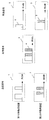
- FIG. 9 is a diagram illustrating an example of a SORM.
- SORM is applied to an uplink that can detect signals of all connected users.
- an example is shown in which there are two mobile station devices (transmitting device, first communication device) that are simultaneously connected to a base station device (receiving device, second communication device).
- transmitting device first communication device
- base station device receiving device, second communication device
- the first mobile station apparatus 101-1 and the second mobile station apparatus 101-2 (hereinafter, the first mobile station apparatus 101-1 and the second mobile station apparatus 101-2 are combined, It is assumed that the mobile station device 101) transmits signals arranged on the frequency axis as transmission signal 102-1 and transmission signal 102-2, respectively.
- the base station apparatus 103 receives each signal.
- the received signal 104 on the frequency axis at this time is as shown in FIG.
- the partial spectrum 104-A of the received signal 104 included in the received signal 104 is received in an overlapping manner because both mobile station apparatuses 101-1 and 101-2 have arranged the signal.
- the transmission signals from the respective mobile station apparatuses can be separated by separating the overlapped signals by turbo equalization.
- signals from each mobile station apparatus 101 can be separated by turbo equalization technology even if partial spectra overlap. For this reason, in consideration of the fact that they may overlap, it is possible to assign a frequency for transmitting a signal to each mobile station apparatus 101 with priority on the propagation path characteristics, thereby improving the transmission characteristics.
- Non-Patent Document 2 partial spectrum retransmission control (Non-Patent Document 2) has been proposed as a single carrier retransmission method.
- Non-Patent Document 2 it is described that only the signal spectrum of the frequency whose propagation path characteristics are significantly deteriorated in the initial transmission is described, but there is no description regarding the SORM, and the cause of the deterioration in the characteristics of the SORM is due to duplication. Considering this, there is a problem that efficient retransmission cannot be performed even if the method of this document is used.
- the present invention has been made in view of such circumstances, and wireless communication that enables efficient retransmission in the case of performing communication by overlapping signals using at least some of the same frequencies at the same time.
- An object is to provide a system, a communication control device, a communication terminal device, and a control program.
- the wireless communication system of the present invention allows wireless communication that allows some or all of the frequencies used when a plurality of first communication devices transmit wireless signals to the second communication device overlap.
- the wireless communication system when each of the first communication devices transmits a retransmission signal to the second communication device, only a partial spectrum that is a part of an initial transmission signal is transmitted to the second communication device. It is characterized by transmitting.
- each first communication device transmits a retransmission signal to the second communication device
- only the partial spectrum that is a part of the initial transmission signal is transmitted to the second communication device.
- efficient retransmission can be performed.
- the partial spectrum is a spectrum arranged at an overlapping frequency when each first communication device transmits an initial transmission signal.
- the partial spectrum is a spectrum that is arranged at an overlapping frequency when each first communication device transmits the initial transmission signal, the first communication device has at least a part of the same frequency at the same time.
- efficient retransmission can be performed.
- the partial spectrum is received in the second communication device by a reception SNR (Signal to Noise power Ratio) or reception of a radio signal received from each of the first communication devices. It is set based on SINR (Signalto
- the partial spectrum is set in the second communication device based on the reception SNR (SignaltoalNoise power Ratio) or the reception SINR (Signal toInterferenceplus Noise power Ratio) of the radio signal received from each first communication device. Therefore, the second communication device can detect the overlapped partial spectrum from the initial transmission signal included in the control signal.
- any one of the first communication devices has a partial spectrum arranged at a frequency that does not overlap with a frequency used by any other first communication device. It transmits to said 2nd communication apparatus, It is characterized by the above-mentioned.
- the first communication device transmits the partial spectrum arranged at a frequency that does not overlap with the frequency used by any other first communication device to the second communication device.
- efficient retransmission can be performed.
- a part or all of the frequencies used when a plurality of first communication devices transmit wireless signals to the second communication device are allowed to overlap.
- the second communication is performed by cyclically shifting the retransmission signal on the frequency axis. It transmits to the apparatus.
- each first communication device transmits a retransmission signal to the second communication device
- the retransmission signal is cyclically shifted on the frequency axis and transmitted to the second communication device.
- the first communication apparatus performs communication by overlapping signals using at least some of the same frequencies at the same time, so that the probability that the same partial spectrum as that of the initial transmission will overlap at the time of retransmission is reduced, so that the retransmission efficiency is improved. Rise.
- the amount by which the retransmission signal is cyclically shifted on the frequency axis is determined by the first communication device transmitting the initial transmission signal in the second communication device. It is characterized in that it is determined on the basis of spectra arranged at overlapping frequencies.
- the amount of cyclic shift of the retransmitted signal on the frequency axis is based on the spectrum arranged in the overlapping frequency when each first communication device transmits the initial transmission signal in the second communication device. Therefore, when the first communication apparatus performs communication by overlapping signals using at least a part of the same frequency at the same time, the probability that the same partial spectrum as that of the initial transmission is overlapped at the time of retransmission is low. Therefore, retransmission efficiency is increased.
- the amount of cyclic shift of the retransmission signal on the frequency axis is the reception of the wireless signal received from each first communication device in the second communication device. It is characterized in that it is set based on SNR (Signal to Noise power Ratio) or received SINR (Signalto Interference plus Noise power Ratio).
- the amount of cyclic shift of the retransmitted signal on the frequency axis is determined by the reception SNR (Signal to Noise power Ratio) or the reception SINR of the radio signal received from each first communication device in the second communication device. Since it is set based on (Signalto
- any one of the first communication devices uses a retransmission signal on a frequency axis so as not to overlap with a frequency used by any other first communication device.
- a cyclic shift is performed above, and transmission is performed to the second communication device.
- any of the first communication devices cyclically shifts the retransmission signal on the frequency axis so as not to overlap with the frequency used by any other first communication device. Probability of overlapping the same partial spectrum as the initial transmission at the time of retransmission when the first communication device performs communication by overlapping signals using at least a part of the same frequency at the same time because it is transmitted to the communication device Thus reducing the efficiency of retransmission.
- the communication control apparatus of this invention is a radio
- a determination unit (corresponding to a data detection / combination unit and an error detection unit) that determines whether or not there is an error in the decoding result of the radio signal received from each communication terminal device. If there is an error as a result of the determination, the communication terminal device includes an overlapping frequency detection unit that detects an overlapping frequency when transmitting an initial transmission signal, and indicates information indicating the detected frequency. And transmitting to each of the communication terminal devices.
- the communication terminal device detects the overlapping frequency when each communication terminal device transmits the initial transmission signal, so that the communication terminal device at least at the same time.
- efficient retransmission can be performed.
- the communication terminal device of the present invention is a radio communication system that allows a part or all of the frequencies used when a plurality of communication terminal devices transmit radio signals to the communication control device.
- a response signal detection unit that detects a response signal received from the communication control device, and the communication control device when the detected response signal is NACK (Negative Acknowledge)
- NACK Negative Acknowledge
- a partial spectrum extraction unit that extracts a partial spectrum that is a part of the initial transmission signal based on the information indicating the overlapped frequency received from the mobile station, and only the extracted partial spectrum is transmitted as a retransmission signal to the communication control device. It is characterized by transmitting to.
- the communication terminal apparatus is a part of the initial transmission signal based on the information indicating the overlapping frequency received from the communication control apparatus. Since the spectrum is extracted and only the extracted partial spectrum is transmitted as a retransmission signal to the communication control apparatus, it is efficient when communication is performed by overlapping signals using at least some of the same frequencies at the same time. Retransmission can be performed.
- the communication control apparatus of the present invention is a radio communication system that allows a part or all of the frequencies used when a plurality of communication terminal apparatuses transmit radio signals to the communication control apparatus. And a determination unit that determines whether or not there is an error in the decoding result of the radio signal received from each of the communication terminal devices, and if the result of the determination is an error, A cyclic shift calculation unit that calculates a cyclic shift amount on the frequency axis, and transmits information indicating the calculated cyclic shift amount to each of the communication terminal devices.
- the communication control device calculates a cyclic shift amount on the frequency axis, and transmits information indicating the calculated cyclic shift amount to each communication terminal device. Therefore, in the case where the communication terminal apparatus performs communication by duplicating signals using at least some of the same frequencies at the same time, the probability that the same partial spectrum as that of the initial transmission is duplicated at the time of retransmission is reduced, so that the retransmission efficiency is improved. Rise.
- the communication terminal device of the present invention is a wireless communication system that allows some or all of the frequencies used when a plurality of communication terminal devices transmit a radio signal to the communication control device.
- a response signal detection unit that detects a response signal received from the communication control device, and the communication control device when the detected response signal is NACK (Negative Acknowledge)
- NACK Negative Acknowledge
- a modulo unit that cyclically shifts the retransmission signal on the frequency axis based on the information indicating the cyclic shift amount received from the transmitter, and transmits the cyclically shifted retransmission signal to the communication control device It is characterized by that.
- the communication terminal apparatus cyclically transmits the retransmission signal on the frequency axis based on the information indicating the cyclic shift amount received from the communication control apparatus. Since the click-shift is performed and the cyclic-shifted retransmission signal is transmitted to the communication control device, in the case of performing communication by overlapping signals using at least a part of the same frequency at the same time, Since the probability that the same partial spectrum overlaps decreases, retransmission efficiency increases.
- control program of the present invention is a wireless communication system that allows a part or all of the frequencies used when a plurality of communication terminal apparatuses transmit wireless signals to the communication control apparatus.
- the communication control device detects an overlapped frequency when each communication terminal device transmits the initial transmission signal, and information indicating the detected frequency is set for each communication. Since transmission is performed to the terminal device, efficient retransmission can be performed when the communication terminal device performs communication by overlapping signals using at least some of the same frequencies at the same time.
- control program of the present invention is a wireless communication system that allows a part or all of the frequencies used when a plurality of communication terminal apparatuses transmit wireless signals to the communication control apparatus.
- a control program for a communication terminal device to be applied in which processing for detecting a response signal received from the communication control device, and when the detected response signal is NACK (Negative Acknowledge), from the communication control device Based on the received information indicating the overlapping frequency, a process of extracting a partial spectrum that is a part of the initial transmission signal, a process of transmitting only the extracted partial spectrum as a retransmission signal to the communication control device, A series of processes is commanded to be readable and executable by a computer.
- the communication terminal apparatus is a part of the initial transmission signal based on the information indicating the overlapping frequency received from the communication control apparatus. Since the spectrum is extracted and only the extracted partial spectrum is transmitted as a retransmission signal to the communication control apparatus, it is efficient when communication is performed by overlapping signals using at least some of the same frequencies at the same time. Retransmission can be performed.
- the control program of the present invention is applied to a radio communication system that allows a part or all of frequencies used when a plurality of communication terminal apparatuses transmit radio signals to the communication control apparatus.
- a series of processes of calculating a cyclic shift amount on the axis and transmitting information indicating the calculated cyclic shift amount to each of the communication terminal devices can be read and executed by a computer. It is characterized by being commanded.
- the communication control device calculates a cyclic shift amount on the frequency axis, and transmits information indicating the calculated cyclic shift amount to each communication terminal device. Therefore, when the communication terminal apparatus performs communication by overlapping signals using at least a part of the same frequency at the same time, the probability that the same partial spectrum as that of the initial transmission is overlapped at the time of retransmission is reduced, so that retransmission efficiency is increased. .
- the control program of the present invention is applied to a radio communication system that allows a part or all of the frequencies used when a plurality of communication terminal apparatuses transmit radio signals to the communication control apparatus.
- a communication terminal device control program for detecting a response signal received from the communication control device, and if the detected response signal is NACK (Negative Acknowledge), received from the communication control device A series of processes including a process of cyclically shifting a retransmission signal on the frequency axis based on information indicating a cyclic shift amount, and a process of transmitting the cyclically shifted retransmission signal to the communication control device Is characterized by being commanded to be readable and executable by a computer.
- the communication terminal apparatus cyclically transmits the retransmission signal on the frequency axis based on the information indicating the cyclic shift amount received from the communication control apparatus. Since the click-shift is performed and the cyclic-shifted retransmission signal is transmitted to the communication control device, in the case of performing communication by overlapping signals using at least a part of the same frequency at the same time, Since the probability that the same partial spectrum overlaps decreases, retransmission efficiency increases.
- efficient retransmission can be performed in the case where communication is performed by overlapping signals using at least some of the same frequencies at the same time.
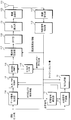
- FIG. 3 is a block diagram showing an example of the configuration of data detection / synthesis units 21-1 to 21-U according to the first embodiment of the present invention. It is a figure which shows an example of the concept of the retransmission method which concerns on the 2nd Embodiment of this invention.
- FIG. 2 is a block diagram illustrating an example of a basic configuration of a mobile station apparatus 101.
- FIG. 3 is a block diagram showing a configuration of a base station apparatus 103.
- MIMO Multiple Input Multiple Output
- the present invention can be applied if it exists.
- FIG. 10 is a block diagram illustrating an example of a basic configuration of the mobile station apparatus 101.
- the mobile station apparatus 101 receives the control signal notified from the base station apparatus 103 on the downlink by the antenna 111, and the radio reception unit 112 down-converts it to a baseband signal and performs A / D conversion.
- the control signal detection unit 113 detects information (MCS) on the modulation scheme and coding rate necessary for generating the data signal, information on the reference signal sequence, frequency allocation information, etc. To do.
- MCS information
- the data signal generation unit 114 first generates a frequency signal of data to be transmitted.
- the information bit string is subjected to error correction coding based on the information on the MCS, modulation symbols such as QPSK and 16QAM are generated, and converted into frequency signals by DFT.
- a reference signal (RS) for propagation path estimation is generated by reference signal generation section 115 based on information relating to the series of reference signals, and multiplexed with a data signal in reference signal multiplexing section 116.
- the frequency allocation unit 117 arranges the frequency based on the frequency allocation information notified by the frequency allocation unit 117, and converts it into a time signal by the IFFT unit 118.
- the CP insertion unit 119 copies a part of the rear of the time signal forward.
- the radio transmission unit 120 performs D / A conversion, up-converts the radio frequency, and then transmits from the antenna 111.
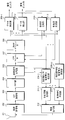
- FIG. 11 is a block diagram showing the configuration of the base station apparatus 103.
- mobile station apparatus 101 of U station is connected to base station apparatus 103.
- a reception signal received by the antenna 201 is converted into a baseband signal by the wireless reception unit 202 and then converted into a digital signal.
- CP is removed by CP removing section 203 and converted into a frequency signal by FFT section 204.
- the multiplexed reference signal of each mobile station apparatus 101 is separated by reference signal separation section 205, and propagation path characteristics and noise power estimation sections 206-1 to 206-U estimate propagation path characteristics and noise power.
- units that need to be processed for each mobile station apparatus 101 are marked as * -1 to * -U.
- the noise includes thermal noise generated in the circuit and interference due to communication of other mobile station apparatuses 101.
- the received signal from which the reference signal is separated is inter-symbol interference (ISI) caused by the delayed wave of the radio propagation path by the signal canceling unit 207, and interference between users that is caused by different mobile station apparatus 101 signals.
- ISI inter-symbol interference
- IUI remove interference
- the frequency demapping unit 208 separates the signals of each mobile station apparatus 101.
- the transmission data is detected by the data detection units 209-1 to 209-U.
- the data detection units 209-1 to 209-U perform equalization processing for suppressing the residual interference components related to ISI and IUI and synthesizing desired signals, and then converting them into the time domain by IDFT, and receiving the received signals of code bits (LLR And error correction decoding is performed. That is, LLRs of information bits and code bits are output from the data detection units 209-1 to 209-U.
- the LLRs of the obtained code bits are output as expected values (hereinafter referred to as soft estimation) of amplitudes of received signals from the mobile station apparatuses 101 in the soft estimation generation units 210-1 to 210-U.
- the signal is input again to the signal cancel unit 207.
- Soft estimation generation sections 210-1 to 210-U calculate the expected value of the amplitude of each modulation symbol called a soft replica from the LLR of the code bit, convert it to a frequency signal by DFT, and each mobile station apparatus 101 transmits The signal is mapped to the same frequency as the frequency assigned at the time. Thereafter, the soft estimation is calculated by multiplying the propagation path characteristics estimated by the propagation path characteristics / noise power estimation units 206-1 to 206-U.
- the repetition of a series of processes of the signal cancellation unit 207, frequency demapping unit 208, data detection units 209-1 to 209-U, and soft estimation generation units 210-1 to 210-U is generally referred to as a turbo equalization technique. This is repeated an arbitrary number of times, a desired number of times, or until there is no detection error, and the decoded bits are obtained by making a hard decision on the LLR of the information bits output from the data detection units 209-1 to 209-U.
- a reference signal sequence for MCS, frequency allocation, and other control purposes calculated from the propagation path characteristics of each mobile station apparatus 101 estimated by the propagation path characteristics / noise power estimation units 206-1 to 206-U
- Control information generators 211-1 to 211 -U generate control information such as information indicating response and response signals, and after D / A conversion and up-conversion to a radio frequency are performed in radio transmission unit 212, antenna 201 To each mobile station apparatus 101.
- signals from each mobile station apparatus 101 are obtained even if partial spectra overlap by a turbo equalization technique configured from the signal cancel unit 207 to the soft estimation generation units 210-1 to 210-U. Can be separated. For this reason, in consideration of the fact that they may overlap, it is possible to assign a frequency for transmitting a signal to each mobile station apparatus 101 with priority on the propagation path characteristics, thereby improving the transmission characteristics.
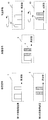
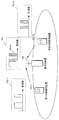
- FIG. 1 is a diagram illustrating an example of a concept of a retransmission method according to the first embodiment of the present invention.
- the state of the frequency signal is taken as an example, and the number of mobile station apparatuses connected to the base station apparatus 103 at the same time is two.
- first mobile station apparatus 101-1 and second mobile station apparatus 101-2 arrange and transmit signals on the frequency axis like transmission signal 1 and transmission signal 2 (this is the initial transmission and transmission). Call).
- the reception signal 3 at this time is expressed as shown in FIG. 1, and the partial spectrum 4 is received in an overlapping manner.
- the first mobile station apparatus 101-1 and the second mobile station apparatus 101-2 perform retransmission processing.
- the cause of the signal detection error is the overlapping partial spectrum 4
- Only the partial spectrum 4 that has been transmitted is retransmitted. That is, only the partial spectrum arranged at the position of partial spectrum 4 at the time of initial transmission (partial spectrums 6 and 8 of retransmission signals 5 and 7) is retransmitted.
- FIG. 2 is a block diagram showing an example of the configuration of the mobile station apparatus 101 according to the first embodiment of the present invention.
- a response signal detection unit 11, a retransmission signal generation unit 12, a partial spectrum extraction unit 13, and an initial transmission / retransmission switching unit 14 are added to the configuration of FIG.
- a feature of the embodiment is a partial spectrum extraction unit 13.
- subjected since it is the same as the function described in FIG. 10, description is abbreviate
- in the base station apparatus 103 it is assumed that information on the spectrum frequency overlapping with the response signal is multiplexed on the control information.
- the information bit string is input to the data signal generation unit 114 and simultaneously to the retransmission signal generation unit 12.
- the response signal detected from the control signal detection unit 113 is input to the response signal detection unit 11 and determines whether it is ACK or NACK.
- the obtained ACK and NACK information is input to the retransmission signal generation unit 12 and the initial transmission / retransmission switching unit 14.
- the retransmission signal generation unit 12 if the response signal from the response signal detection unit 11 is NACK, the same frequency signal is generated from the information bit string transmitted at the previous transmission opportunity and input to the partial spectrum extraction unit 13.
- the partial spectrum extraction unit 13 extracts the overlapping partial spectrum based on the information regarding the frequency of the overlapping spectrum with the initial transmission signal included in the control signal.
- the frequency of the overlapping spectrum may be based on the received signal-to-noise power ratio (SNR) of the received signal from the mobile station apparatus 101 in the base station apparatus 103. Further, it may be based on SINR (Signal to Interference plus Noise power Ratio) including interference in noise.
- SINR Signal-to-noise power ratio
- the initial transmission / retransmission switching unit 14 inputs a signal from the data signal generation unit 114 to the reference signal multiplexing unit 116, and in the case of NACK Switches to input the retransmission signal of the partial spectrum output from the partial spectrum extraction unit 13 to the reference signal multiplexing unit 116.
- the retransmission signal is generated again from the information bit string. However, since the same signal as the transmission data transmitted at the previous transmission opportunity is generated, the transmission data at the previous transmission opportunity is buffered.
- the functional block having the function to be stored may be replaced with the retransmission signal generation unit 12.
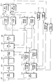
- FIG. 3 is a block diagram showing an example of the configuration of the base station apparatus 103 according to the first embodiment of the present invention.
- the configuration is the same as that of FIG. 11, but the data detection units 209-1 to 209-U of FIG.
- the data detection / combination units 21-1 to 21-U are collectively replaced with the data detection / synthesis unit 21).
- error detection units 22-1 to 22-U that detect whether the decoded bit string is correct
- overlap frequency detection units 23-1 to 23-U that detect information on the frequency of the overlapping spectrum
- ACK when decoding is correctly performed
- the response signal generators 24-1 to 24-U that perform NACK when there is an error in the decoding result are different from those in FIG. 11, and the feature of the present embodiment is the overlap frequency detectors 23-1 to 23-U. is there.
- the received signal from each mobile station apparatus 101 is initially transmitted by the data detection / combination units 21-1 to 21-U, the same processing as the data detection units 209-1 to 209-U in FIG. If so, it is combined with the received signal at the time of initial transmission.
- the decoded bit strings output from the data detection / combination units 21-1 to 21-U are determined by the error detection units 22-1 to 22-U to determine whether the decoding result is correct, and the determination result is the overlap frequency detection unit 23. -1 to 23-U and response signal generators 24-1 to 24-U.
- the overlapping frequency detectors 23-1 to 23-U output the frequency position of the overlapping partial spectrum
- the response signal generators 24-1 to 24-U output ACK or NACK.
- the information is input to the control information generation units 211-1 to 211-U. Next, the data detection / synthesis units 21-1 to 21-U will be described.
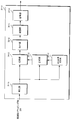
- FIG. 4 is a block diagram showing an example of the configuration of the data detection / synthesis units 21-1 to 21-U according to the first embodiment of the present invention.
- the data detection / synthesis unit 21-U includes an equalization unit 31-U, an initial transmission signal holding unit 32-U, a synthesis unit 33-U, a switching unit 34-U, an IDFT unit 35-U, a demodulation unit 36-U, It comprises a decoding unit 37-U.
- the signal input from the frequency demapping unit 208 is equalized by the equalization unit 31-U.
- the equalized signal is held until the decoded bit is correctly detected by the initial transmission signal holding unit 32-U. If it is a retransmission signal, the transmission signal at the time of initial transmission held by the initial transmission signal holding unit 32-U is called, and the signal is synthesized by the synthesis unit 33-U. At this time, since the retransmitted signal is a partial spectrum having a bandwidth that is at least equal to the frequency bandwidth of the initial transmission signal, the retransmitted signal is synthesized by combining the frequency positions.
- N DFT the number of subcarriers in the initial transmission
- the partial spectrum used for retransmission be the Mth partial spectrum from m of the initial transmission signal.
- Equation (1) S com (k) is the amplitude of the kth subcarrier after synthesis, S est f is the amplitude of the initial transmission signal of the kth subcarrier, and S est Re is the kth subcarrier. This is the amplitude of the carrier retransmission signal.
- the subcarrier index is a virtual frequency index after performing a demapping process for extracting only a frequency signal to which a desired signal is assigned from a frequency at which the signal is actually arranged. As described above, by combining and retransmitting / combining only the overlapped spectrum, efficient retransmission can be performed.
- a simple addition may be used, a method of selecting a larger amplitude of the spectrum amplitude of each discrete frequency of the initial transmission signal and the retransmission signal, or a maximum ratio synthesis. Weighted synthesis may be performed.
- information frequency index or the like
- the partial spectrum may be retransmitted in a predetermined pattern. In this case, it is not necessary to notify in particular.
- the first embodiment discloses a method of rearranging and transmitting only overlapping partial spectra at the time of retransmission
- the frequency spectrum is cyclically shifted (modulo, remainder) on the frequency axis. Then, the overlapping partial spectrum is rearranged.
- FIG. 5 is a diagram illustrating an example of a concept of a retransmission method according to the second embodiment of the present invention.
- the frequency signal is cyclically shifted at the time of retransmission.
- partial spectrums 4 arranged at overlapping frequencies are partially spectrumd 42 in retransmission signal 41 of first mobile station apparatus 101-1 and partially transmitted in retransmission signal 43 of second mobile station apparatus 101-2. It is assumed that a cyclic shift is performed so as to be arranged in the spectrum 44. Thereby, since the probability that the same partial spectrum as the initial transmission overlaps at the time of retransmission decreases, retransmission efficiency increases.
- FIG. 6 is a block diagram showing an example of the configuration of the mobile station apparatus 101 according to the second embodiment of the present invention.
- the partial spectrum extraction unit 13 of FIG. 2 is a modulo unit 51, which is a feature of the present embodiment.
- the modulo unit 51 gives a cyclic shift to the same frequency signal as the cyclic transmission amount detected by the control signal detection unit 113 and the initial transmission signal output from the retransmission signal generation unit 12. . If the cyclic shift amount given to the u th mobile station apparatus 101 is K (u) and the original signal bandwidth of the u th mobile station apparatus 101 is N DFT (u), the cyclically shifted k th frequency.
- the amplitude S cyc (u, k) represented by the complex number of the frequency signal at is expressed by Equation (2).
- k is a natural number from 0 to N DFT (u) ⁇ 1
- S (u, k) is represented by a complex number of frequency signals at the k-th frequency of the original frequency signal of the u-th mobile station apparatus 101. Amplitude.
- K (u) is set for each mobile station apparatus 101 so that the processing of equation (2) can be performed.
- K (u) is set for each mobile station apparatus 101 so that the processing of equation (2) can be performed.
- the frequency of the overlapping spectrum may be based on a received signal-to-noise power ratio (SNR) of the received signal from the mobile station apparatus 101 in the base station apparatus 103.
- SINR Signal-to-noise power ratio
- SINR Signal to Interference plus Noise power Ratio
- this embodiment is a cyclic shift, the frequency arrangement of the initial transmission signal may be reversed as in the case of mirroring.
- FIG. 7 is a block diagram showing an example of the configuration of the base station apparatus 103 according to the second embodiment of the present invention.
- cyclic shift calculation units 61-1 to 61-U for modulo are added, and this is the point of this embodiment.
- the cyclic shift calculation units 61-1 to 61-U calculate the amount of cyclic shift from the overlapping frequency information detected by the overlapping frequency detection units 23-1 to 23-U.
- the amount of cyclic shift may be set to the same amount for all mobile station apparatuses 101 at the same time, or may be determined for each mobile station apparatus 101.
- an example of the setting method will be described.
- the p-th to P-th frequency signals are set to be cyclically shifted by p so that there is a high possibility that the p-th to P-th frequency signals will not overlap in retransmission.
- FIG. 8 is a conceptual diagram specifically showing the cyclic shift setting method according to the second embodiment of the present invention.
- the present invention is based on the essence of retransmitting duplicated spectrums with high accuracy, and therefore a retransmission method that reduces the probability that duplicated spectra are duplicated again is included in the present invention.
- the basic configuration of the data detecting / synthesizing unit 21 is the same as that shown in FIG. 4, but the synthesizing process is performed after returning the spectrum cyclically shifted by modulo to the original order.
- this combining process is not specifically described, it is technical common sense to restore the spectrum and combine the initial transmission signal and the retransmission signal, and the essence of the present invention is the resending in the SORM.
- control or the probability of overlapping is made low so that the overlapping spectrum does not overlap as much as possible at the time of retransmission.
- the program that operates in the mobile station apparatus 101 and the base station apparatus 103 related to the present invention is a program (a program that causes a computer to function) that controls the CPU and the like so as to realize the functions of the above-described embodiments related to the present invention.
- Information handled by these devices is temporarily stored in the RAM at the time of processing, then stored in various ROMs and HDDs, read out by the CPU, and corrected and written as necessary.
- a recording medium for storing the program a semiconductor medium (for example, ROM, nonvolatile memory card, etc.), an optical recording medium (for example, DVD, MO, MD, CD, BD, etc.), a magnetic recording medium (for example, magnetic tape, Any of a flexible disk etc. may be sufficient.
- the processing is performed in cooperation with the operating system or other application programs.
- the functions of the invention may be realized.
- the program when distributing to the market, can be stored and distributed on a portable recording medium, or transferred to a server computer connected via a network such as the Internet.
- the storage device of the server computer is also included in the present invention.
- LSI which is typically an integrated circuit.
- Each functional block of the mobile station apparatus 101 and the base station apparatus 103 may be individually chipped, or a part or all of them may be integrated into a chip.
- the method of circuit integration is not limited to LSI, and may be realized by a dedicated circuit or a general-purpose processor.
- an integrated circuit based on the technology can also be used.
Landscapes
- Engineering & Computer Science (AREA)
- Computer Networks & Wireless Communication (AREA)
- Signal Processing (AREA)
- Mobile Radio Communication Systems (AREA)
- Detection And Prevention Of Errors In Transmission (AREA)
- Communication Control (AREA)
Applications Claiming Priority (2)
| Application Number | Priority Date | Filing Date | Title |
|---|---|---|---|
| JP2010-186404 | 2010-08-23 | ||
| JP2010186404A JP5653129B2 (ja) | 2010-08-23 | 2010-08-23 | 無線通信システム、通信制御装置、通信端末装置および制御プログラム |
Publications (1)
| Publication Number | Publication Date |
|---|---|
| WO2012026246A1 true WO2012026246A1 (ja) | 2012-03-01 |
Family
ID=45723255
Family Applications (1)
| Application Number | Title | Priority Date | Filing Date |
|---|---|---|---|
| PCT/JP2011/066475 Ceased WO2012026246A1 (ja) | 2010-08-23 | 2011-07-20 | 無線通信システム、通信制御装置、通信端末装置および制御プログラム |
Country Status (2)
| Country | Link |
|---|---|
| JP (1) | JP5653129B2 (enExample) |
| WO (1) | WO2012026246A1 (enExample) |
Cited By (1)
| Publication number | Priority date | Publication date | Assignee | Title |
|---|---|---|---|---|
| CN114374586A (zh) * | 2020-10-14 | 2022-04-19 | 鹤壁天海电子信息系统有限公司 | 数据传输方法、发射机和接收机 |
Families Citing this family (3)
| Publication number | Priority date | Publication date | Assignee | Title |
|---|---|---|---|---|
| JP2013005139A (ja) * | 2011-06-15 | 2013-01-07 | Sharp Corp | 受信装置、周波数割当方法、制御プログラムおよび集積回路 |
| KR102268512B1 (ko) * | 2014-07-15 | 2021-06-23 | 에스케이텔레콤 주식회사 | 기지국장치 및 기지국장치의 동작 방법, 단말장치 |
| JP6631929B2 (ja) * | 2016-08-10 | 2020-01-15 | シャープ株式会社 | 通信システム、基地局装置、端末装置、通信方法およびプログラム |
Citations (4)
| Publication number | Priority date | Publication date | Assignee | Title |
|---|---|---|---|---|
| JP2003152691A (ja) * | 2001-08-31 | 2003-05-23 | Matsushita Electric Ind Co Ltd | 送受信装置及び送受信方法 |
| JP2003309535A (ja) * | 2002-04-12 | 2003-10-31 | Matsushita Electric Ind Co Ltd | マルチキャリア送信装置、マルチキャリア受信装置及びマルチキャリア送信方法 |
| JP2009105746A (ja) * | 2007-10-24 | 2009-05-14 | Fujitsu Ltd | 無線通信システムにおける上り通信方法並びに無線通信システム、無線端末及び無線基地局 |
| JP2011119844A (ja) * | 2009-12-01 | 2011-06-16 | Nippon Telegr & Teleph Corp <Ntt> | 無線通信システム、送信装置、受信装置、無線通信方法及びプログラム |
-
2010
- 2010-08-23 JP JP2010186404A patent/JP5653129B2/ja active Active
-
2011
- 2011-07-20 WO PCT/JP2011/066475 patent/WO2012026246A1/ja not_active Ceased
Patent Citations (4)
| Publication number | Priority date | Publication date | Assignee | Title |
|---|---|---|---|---|
| JP2003152691A (ja) * | 2001-08-31 | 2003-05-23 | Matsushita Electric Ind Co Ltd | 送受信装置及び送受信方法 |
| JP2003309535A (ja) * | 2002-04-12 | 2003-10-31 | Matsushita Electric Ind Co Ltd | マルチキャリア送信装置、マルチキャリア受信装置及びマルチキャリア送信方法 |
| JP2009105746A (ja) * | 2007-10-24 | 2009-05-14 | Fujitsu Ltd | 無線通信システムにおける上り通信方法並びに無線通信システム、無線端末及び無線基地局 |
| JP2011119844A (ja) * | 2009-12-01 | 2011-06-16 | Nippon Telegr & Teleph Corp <Ntt> | 無線通信システム、送信装置、受信装置、無線通信方法及びプログラム |
Non-Patent Citations (4)
| Title |
|---|
| JUNGO GOTO ET AL.: "A Study on Design of Turbo Code for Spectrum-Overlapped Resource Management", IEICE TECHNICAL REPORT, vol. 109, no. 440, 24 February 2010 (2010-02-24), pages 321 - 326 * |
| TOSHIAKI OHNISHI ET AL.: "A Partial Spectrum Retransmission Scheme using a Dynamic Spectrum Control for Broadband Single Carrier Transmission Systems", THE 18TH ANNUAL IEEE INTERNATIONAL SYMPOSIUM ON PERSONAL, INDOOR AND MOBILE RADIO COMMUNICATIONS, 2007. PIMRC 2007, 3 September 2007 (2007-09-03) * |
| TOSHIAKI ONISHI ET AL.: "A Study on Mutual Information based partial Waveform Re- Transmission Control Technique", IEICE TECHNICAL REPORT, vol. 106, no. 480, 19 January 2007 (2007-01-19), pages 109 - 114 * |
| TOSHIAKI ONISHI ET AL.: "A Study on Throughput Performances of Dynamic Spectrum Control based Partial Spectrum Re-transmission Technique", 2007 NEN THE INSTITUTE OF ELECTRONICS, INFORMATION AND COMMUNICATION ENGINEERS SOGO TAIKAI KOEN RONBUNSHU TSUSHIN 1, 7 March 2007 (2007-03-07), pages 535 * |
Cited By (2)
| Publication number | Priority date | Publication date | Assignee | Title |
|---|---|---|---|---|
| CN114374586A (zh) * | 2020-10-14 | 2022-04-19 | 鹤壁天海电子信息系统有限公司 | 数据传输方法、发射机和接收机 |
| CN114374586B (zh) * | 2020-10-14 | 2024-02-27 | 鹤壁天海电子信息系统有限公司 | 数据传输方法、发射机和接收机 |
Also Published As
| Publication number | Publication date |
|---|---|
| JP5653129B2 (ja) | 2015-01-14 |
| JP2012044611A (ja) | 2012-03-01 |
Similar Documents
| Publication | Publication Date | Title |
|---|---|---|
| EP2247019A1 (en) | Communication device, communication system, reception method, and communication method | |
| JP4903122B2 (ja) | 無線通信システム、受信装置、受信方法 | |
| JP5770464B2 (ja) | 通信システム、送信装置、及び、受信装置 | |
| WO2012173142A1 (ja) | 受信装置、周波数割当方法、制御プログラムおよび集積回路 | |
| JP5254180B2 (ja) | 受信装置、受信方法、通信システムおよび通信方法 | |
| WO2016052031A1 (ja) | 基地局装置および端末装置 | |
| JP5653129B2 (ja) | 無線通信システム、通信制御装置、通信端末装置および制御プログラム | |
| JP2012114723A (ja) | 無線送信装置 | |
| EP2247017A1 (en) | Transmission device, reception device, communication system, and communication method | |
| JP5487090B2 (ja) | 無線信号処理方法および無線通信装置 | |
| JP5394894B2 (ja) | 無線通信システム、通信装置、通信方法、及び、プログラム | |
| JP5770558B2 (ja) | 受信装置、プログラムおよび集積回路 | |
| JP5662955B2 (ja) | 受信装置、及び受信方法 | |
| JP2012060407A (ja) | 受信装置、通信システム、受信装置の制御プログラムおよび集積回路 | |
| JP2012010290A (ja) | 無線通信システム、受信装置、受信制御方法、受信制御プログラム、及びプロセッサ | |
| JP2010199729A (ja) | 通信システム、通信方法、受信装置および受信方法 | |
| JP5535759B2 (ja) | 無線通信システム、送信装置、受信装置、通信方法、送信方法及び受信方法 | |
| JP5441811B2 (ja) | 受信装置、基地局装置、無線通信システム、伝搬路推定方法、制御プログラムおよび集積回路 | |
| WO2014027667A1 (ja) | 通信システム、通信装置および通信方法 | |
| WO2013031538A1 (ja) | 送信方式決定装置、基地局装置、プロセッサ、送信方式決定方法、送信方式決定プログラム、及び送信装置 | |
| WO2013027635A1 (ja) | 通信装置、通信方法、プログラムおよび集積回路 | |
| JP2011049766A (ja) | 無線受信装置、無線受信方法、及び無線受信プログラム |
Legal Events
| Date | Code | Title | Description |
|---|---|---|---|
| 121 | Ep: the epo has been informed by wipo that ep was designated in this application |
Ref document number: 11819714 Country of ref document: EP Kind code of ref document: A1 |
|
| NENP | Non-entry into the national phase |
Ref country code: DE |
|
| 122 | Ep: pct application non-entry in european phase |
Ref document number: 11819714 Country of ref document: EP Kind code of ref document: A1 |