WO2012020720A1 - 磁気共鳴イメージング装置および磁気共鳴イメージング方法 - Google Patents
磁気共鳴イメージング装置および磁気共鳴イメージング方法 Download PDFInfo
- Publication number
- WO2012020720A1 WO2012020720A1 PCT/JP2011/068014 JP2011068014W WO2012020720A1 WO 2012020720 A1 WO2012020720 A1 WO 2012020720A1 JP 2011068014 W JP2011068014 W JP 2011068014W WO 2012020720 A1 WO2012020720 A1 WO 2012020720A1
- Authority
- WO
- WIPO (PCT)
- Prior art keywords
- magnetic field
- data
- template data
- magnetic resonance
- resonance imaging
- Prior art date
- Legal status (The legal status is an assumption and is not a legal conclusion. Google has not performed a legal analysis and makes no representation as to the accuracy of the status listed.)
- Ceased
Links
Images


Classifications
-
- G—PHYSICS
- G01—MEASURING; TESTING
- G01R—MEASURING ELECTRIC VARIABLES; MEASURING MAGNETIC VARIABLES
- G01R33/00—Arrangements or instruments for measuring magnetic variables
- G01R33/20—Arrangements or instruments for measuring magnetic variables involving magnetic resonance
- G01R33/44—Arrangements or instruments for measuring magnetic variables involving magnetic resonance using nuclear magnetic resonance [NMR]
- G01R33/48—NMR imaging systems
- G01R33/54—Signal processing systems, e.g. using pulse sequences ; Generation or control of pulse sequences; Operator console
- G01R33/56—Image enhancement or correction, e.g. subtraction or averaging techniques, e.g. improvement of signal-to-noise ratio and resolution
- G01R33/561—Image enhancement or correction, e.g. subtraction or averaging techniques, e.g. improvement of signal-to-noise ratio and resolution by reduction of the scanning time, i.e. fast acquiring systems, e.g. using echo-planar pulse sequences
- G01R33/5615—Echo train techniques involving acquiring plural, differently encoded, echo signals after one RF excitation, e.g. using gradient refocusing in echo planar imaging [EPI], RF refocusing in rapid acquisition with relaxation enhancement [RARE] or using both RF and gradient refocusing in gradient and spin echo imaging [GRASE]
- G01R33/5616—Echo train techniques involving acquiring plural, differently encoded, echo signals after one RF excitation, e.g. using gradient refocusing in echo planar imaging [EPI], RF refocusing in rapid acquisition with relaxation enhancement [RARE] or using both RF and gradient refocusing in gradient and spin echo imaging [GRASE] using gradient refocusing, e.g. EPI
-
- G—PHYSICS
- G01—MEASURING; TESTING
- G01R—MEASURING ELECTRIC VARIABLES; MEASURING MAGNETIC VARIABLES
- G01R33/00—Arrangements or instruments for measuring magnetic variables
- G01R33/20—Arrangements or instruments for measuring magnetic variables involving magnetic resonance
- G01R33/44—Arrangements or instruments for measuring magnetic variables involving magnetic resonance using nuclear magnetic resonance [NMR]
- G01R33/48—NMR imaging systems
- G01R33/54—Signal processing systems, e.g. using pulse sequences ; Generation or control of pulse sequences; Operator console
- G01R33/56—Image enhancement or correction, e.g. subtraction or averaging techniques, e.g. improvement of signal-to-noise ratio and resolution
- G01R33/565—Correction of image distortions, e.g. due to magnetic field inhomogeneities
- G01R33/56554—Correction of image distortions, e.g. due to magnetic field inhomogeneities caused by acquiring plural, differently encoded echo signals after one RF excitation, e.g. correction for readout gradients of alternating polarity in EPI
Definitions
- Embodiments described herein relate generally to a magnetic resonance imaging apparatus and a magnetic resonance imaging method.
- MRI is an imaging method in which a nuclear spin of a subject placed in a static magnetic field is magnetically excited with an RF pulse having a Larmor frequency, and an image is reconstructed from MR signals generated along with this excitation.
- the MRI means magnetic resonance imaging
- the RF pulse means radio frequency pulse
- the MR signal means nuclear magnetic resonance signal. .
- EPI echo planar imaging
- SE EPI using spin echo method SE: spin echo
- field echo that collects echo signals generated after application of excitation pulse
- FE EPI using the method
- FFE EPI using the FFE (Fast FE) method.
- EPI that generates image data for one sheet by combining echo train data obtained by applying a plurality of excitation pulses
- multi-shot EPI whereas only one excitation pulse is applied.
- the EPI for reconstructing an image is called a single shot EPI.
- phase error In the EPI sequence, imaging is performed while reversing the gradient magnetic field at a high speed, so that the collected echo data includes a phase error. Therefore, distortion occurs in the image reconstructed based on the echo data.
- Two main causes of phase error in EPI are considered to be static magnetic field inhomogeneity and eddy magnetic field generated by switching of a gradient magnetic field (see, for example, Non-Patent Document 1 and Non-Patent Document 2).
- phase error due to the above-mentioned static magnetic field inhomogeneity differs depending on the signal intensity distribution of the imaging target and the spatial distribution of the static magnetic field inhomogeneity in the imaging region.
- the phase error due to the eddy magnetic field has a primary gradient mainly in the readout direction of the real space, and the direction of the phase gradient is reversed depending on the polarity of the gradient magnetic field in the readout direction during echo data collection.
- Patent Document 1 As a conventional technique for reducing a phase error due to static magnetic field inhomogeneity, there is a method for correcting static magnetic field inhomogeneity described in Patent Document 1.
- Patent Document 2 As a method for reducing the phase error due to factors other than the static magnetic field inhomogeneity, the technique described in Patent Document 2 is known.
- the problem to be solved by the present invention is to provide a technique different from the conventional technique for further reducing image distortion caused by a phase error in EPI.
- the MRI apparatus transmits an excitation pulse for causing nuclear magnetic resonance to a subject in a static magnetic field, collects a plurality of echo signals generated by repeated polarity reversal of a readout direction gradient magnetic field, EPI that reconstructs image data based on a plurality of echo signals can be executed, and includes a first acquisition unit, a second acquisition unit, and a correction unit.
- the first collection unit collects a plurality of generated echo signals as first template data by executing an EPI echo signal collection sequence including application of a phase encoding direction gradient magnetic field.
- the second collection unit collects the EPI echo signal collection sequence including the application of the gradient magnetic field in the phase encoding direction and the start timing of the application of the gradient magnetic field in the reading direction from the time when the first template data is collected. By executing later, a plurality of generated echo signals are collected as second template data.
- the correction unit corrects at least a phase error included in the echo signal by using the first and second template data.
- image distortion caused by a phase error in EPI can be further reduced by a technique different from the conventional technique.
- the MRI method includes EPI and has the following steps.
- One is a step of collecting a plurality of generated echo signals as first template data by executing an EPI echo signal collection sequence including application of a gradient magnetic field in the phase encoding direction.
- One includes the application of a gradient magnetic field in the phase encoding direction, and executes the EPI echo signal collection sequence after the collection of the first template data, with the application timing of the gradient magnetic field in the readout direction being shifted from the time of collecting the first template data.
- This is a step of collecting a plurality of generated echo signals as second template data.
- One is a step of correcting at least a phase error included in the echo signal using the first and second template data.
- image distortion caused by a phase error in EPI can be further reduced by a technique different from the conventional technique.
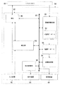
- FIG. 1 is a block diagram showing an overall configuration of an MRI apparatus according to an embodiment.
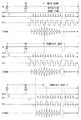
- the functional block diagram of the computer 58 shown in FIG. FIG. 5 is a timing chart showing an example of a pulse sequence of main scan and template shots 1 and 2 as a spin echo single shot EPI in the first embodiment.
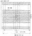
- sequence order of MR signal on k space, when the number of matrix elements of a phase encoding and a frequency encoding is 256x256.
- the schematic diagram which shows an example of the 1st phase image obtained from the template data 1.
- FIG. The schematic diagram which shows an example of the 2nd phase image obtained from the template data 2.
- FIG. 9 is an example of an image obtained by imaging the same phantom as in FIG. 8 after correcting the static magnetic field inhomogeneity by the magnetic field correction map before the main scan.
- FIG. 9 is a schematic diagram illustrating a difference between a case where correction by a magnetic field correction map is not performed (FIG. 8) and a case where correction is performed (FIG. 9) by extracting four strain regions in FIG. 8.
- FIG. 3 is a flowchart showing a flow of operations of the MRI apparatus in the first embodiment.
- FIG. 10 is a timing chart showing an example of a pulse sequence of main scan and template shots 1 and 2 ′ as a spin echo single shot EPI in the second embodiment.
- the flowchart which shows the flow of operation
- FIG. 10 is a timing chart showing an example of a pulse sequence of template shots 1, 2, and 3 as a spin echo single shot EPI in the third embodiment.
- the timing diagram which shows an example of the pulse sequence of the main scan as FID type single shot EPI, template shot 1 ", 2".
- FIG. 1 is a block diagram showing the overall configuration of the MRI apparatus 20 in the first embodiment.
- the MRI apparatus 20 includes a cylindrical static magnetic field magnet 22 for forming a static magnetic field, a cylindrical shim coil 24 provided with the same axis inside the static magnetic field magnet 22, A gradient magnetic field coil 26, an RF coil 28, a control device 30, and a bed 32 on which the subject P is placed are provided.
- the X-axis, Y-axis, and Z-axis that are orthogonal to each other in the apparatus coordinate system are defined as follows.
- the static magnetic field magnet 22 and the shim coil 24 are arranged so that their axial directions are orthogonal to the vertical direction, and the axial direction of the static magnetic field magnet 22 and the shim coil 24 is the Z-axis direction.
- the vertical direction is the Y-axis direction
- the bed 32 is arranged such that the normal direction of the surface for placing the top plate is the Y-axis direction.
- the control device 30 includes a static magnetic field power supply 40, a shim coil power supply 42, a gradient magnetic field power supply 44, an RF transmitter 46, an RF receiver 48, a sequence controller 56, and a computer 58.
- the gradient magnetic field power supply 44 has an X-axis gradient magnetic field power supply 44x, a Y-axis gradient magnetic field power supply 44y, and a Z-axis gradient magnetic field power supply 44z.
- the computer 58 includes an arithmetic device 60, an input device 62, a display device 64, and a storage device 66.
- the static magnetic field magnet 22 is connected to the static magnetic field power supply 40, and forms a static magnetic field in the imaging space by the current supplied from the static magnetic field power supply 40.
- the imaging space means, for example, a space in the gantry where the subject P is placed and a static magnetic field is applied.
- the gantry is a structure formed, for example, in a cylindrical shape so as to include the static magnetic field magnet 22, the shim coil 24, the gradient magnetic field coil 26, and the RF coil 28.
- the gantry and the bed 32 are configured so that the bed 32 on which the subject P is placed can move inside the gantry. 1, the static magnetic field magnet 22, the shim coil 24, the gradient magnetic field coil 26, and the RF coil 28 in the gantry are illustrated as components, and the gantry itself is not illustrated.
- the imaging area is an MR signal collection range used for generating “one image” or “one set of images”, for example, and means an area set as a part of the imaging space.
- “one image” and “one set of images” may be a two-dimensional image or a three-dimensional image.
- “one set of images” means “multiple images” when MR signals of “multiple images” are collected in one pulse sequence, such as multi-slice imaging. It is.
- the imaging region is defined three-dimensionally by, for example, the apparatus coordinate system.
- the imaging region is referred to as a slice if the region is thin, and is referred to as a slab if the region is thick to some extent.
- the shim coil 24 is connected to a shim coil power source 42 and makes the static magnetic field uniform by a current supplied from the shim coil power source 42.
- the static magnetic field magnet 22 is often composed of a superconducting coil, and is connected to the static magnetic field power source 40 and supplied with current when excited, but after being excited, it is disconnected. Is common.
- the static magnetic field magnet 22 may be formed of a permanent magnet without providing the static magnetic field power supply 40.
- the gradient magnetic field coil 26 includes an X-axis gradient magnetic field coil 26 x, a Y-axis gradient magnetic field coil 26 y, and a Z-axis gradient magnetic field coil 26 z, and is formed in a cylindrical shape inside the static magnetic field magnet 22.
- the X-axis gradient magnetic field coil 26x, the Y-axis gradient magnetic field coil 26y, and the Z-axis gradient magnetic field coil 26z are connected to the X-axis gradient magnetic field power source 44x, the Y-axis gradient magnetic field power source 44y, and the Z-axis gradient magnetic field power source 44z, respectively.
- the X-axis gradient magnetic field power supply 44x, the Y-axis gradient magnetic field power supply 44y, and the Z-axis gradient magnetic field power supply 44z respectively supply the X-axis gradient magnetic field coil 26x, the Y-axis gradient magnetic field coil 26y, and the Z-axis gradient magnetic field coil 26z
- An axial gradient magnetic field Gx, a Y-axis gradient magnetic field Gy, and a Z-axis gradient magnetic field Gz are formed in the imaging region.
- the gradient magnetic fields Gx, Gy, and Gz in the X, Y, and Z axis directions of the apparatus coordinate system are synthesized, and the slice selection direction gradient magnetic field Gss, the phase encoding direction gradient magnetic field Gpe, and the readout direction (frequency) are used as logical axes.
- Gradient magnetic field Gro can be set arbitrarily.
- the gradient magnetic fields Gss, Gpe, and Gro in the slice selection direction, the phase encoding direction, and the readout direction are superimposed on the static magnetic field.
- the RF transmitter 46 generates an RF pulse (RF current pulse) with a Larmor frequency for causing nuclear magnetic resonance based on the control information input from the sequence controller 56 and transmits this to the RF coil 28 for transmission.
- the RF coil 28 includes a whole body coil for transmitting and receiving RF pulses built in the gantry, and a local coil for receiving RF pulses provided in the vicinity of the bed 32 or the subject P.
- the transmitting RF coil 28 receives the RF pulse from the RF transmitter 46 and transmits it to the subject P.
- the receiving RF coil 28 receives an MR signal (high frequency signal) generated by exciting the nuclear spin inside the subject P by the RF pulse, and this MR signal is detected by the RF receiver 48. .
- the RF receiver 48 performs various signal processing such as pre-amplification, intermediate frequency conversion, phase detection, low-frequency amplification, and filtering on the detected MR signal, and then performs A / D (analog to digital) conversion. Then, raw data (raw data) which is digitized complex data is generated. The RF receiver 48 inputs the generated raw data of the MR signal to the sequence controller 56. The arithmetic device 60 performs system control of the entire MRI apparatus 20.
- the sequence controller 56 stores control information necessary for driving the gradient magnetic field power supply 44, the RF transmitter 46, and the RF receiver 48 in accordance with a command from the arithmetic unit 60.
- the control information here is, for example, sequence information describing operation control information such as the intensity, application time, and application timing of the pulse current to be applied to the gradient magnetic field power supply 44.
- the sequence controller 56 drives the gradient magnetic field power supply 44, the RF transmitter 46, and the RF receiver 48 in accordance with the stored predetermined sequence, whereby the X-axis gradient magnetic field Gx, the Y-axis gradient magnetic field Gy, the Z-axis gradient magnetic field Gz, and RF Generate a pulse. Further, the sequence controller 56 receives raw data (raw data) of the MR signal input from the RF receiver 48 and inputs this to the arithmetic device 60.
- FIG. 2 is a functional block diagram of the computer 58 shown in FIG.
- the computing device 60 of the computer 58 includes an MPU (Micro Processor Unit) 86, a system bus 88, an image reconstruction unit 90, an image database 94, an image processing unit 96, a display control unit 98, and a correction unit 100. Is provided.
- MPU Micro Processor Unit
- the MPU 86 performs system control of the entire MRI apparatus 20 via wiring such as the system bus 88 in setting of imaging conditions, imaging operation, and image display after imaging.
- Imaging condition refers to, for example, transmitting an RF signal or the like under any kind of pulse sequence such as spin echo or EPI, and collecting MR signals from the subject under any condition. Or the meaning.
- Each item of “imaging condition” includes, for example, an imaging area as position information in an imaging space, a flip angle, a repetition time (TR), a number of slices, a number of steps in a phase encoding direction and a frequency encoding direction. And types of pulse sequences such as EPI and spin echo method.
- the MPU 86 also functions as an imaging condition setting unit, sets imaging conditions including a pulse sequence based on instruction information from the input device 62, and inputs the set imaging conditions to the sequence controller 56. For this purpose, the MPU 86 controls the display control unit 98 to display the imaging condition setting screen information on the display device 64.
- the input device 62 provides a user with a function of setting imaging conditions and image processing conditions.
- the image reconstruction unit 90 has a k-space database 92 inside.
- the image reconstruction unit 90 arranges raw data of MR signals input from the sequence controller 56 as k-space data in the k-space formed in the k-space database 92.
- the image reconstruction unit 90 performs image reconstruction processing on the k-space data, generates image data of each slice of the subject P, and stores the generated image data in the image database 94.
- the image processing unit 96 takes in image data from the image database 94, performs predetermined image processing on the image data, and stores the image data after the image processing in the storage device 66 as display image data.
- the storage device 66 stores the above-described display image data with the imaging conditions used to generate the display image data, information about the subject P (patient information), and the like attached thereto as incidental information.
- the display control unit 98 causes the display device 64 to display an imaging condition setting screen and an image indicated by image data generated by imaging under the control of the MPU 86.
- the correction unit 100 performs the following two operations based on the collected data of the template shots 1 and 2 performed as a pre-scan before collecting the target MR signals for the image (main scan).
- the correction unit 100 generates a magnetic field correction map for correcting (homogenizing) the static magnetic field inhomogeneity.
- the correction unit 100 generates phase correction data for removing the influence of the phase error included in the MR signal when the image data is reconstructed from the MR signal collected in the main scan. Details of these will be described below.
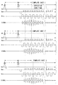
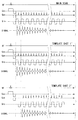
- FIG. 3 is a timing chart showing an example of each pulse sequence of the main scan and template shots 1 and 2.
- the upper, middle, and lower stages of FIG. 3 show the pulse sequences of the main scan (MAIN SCAN), template shot 1 (TEMPLATE SHOT 1), and template shot 2 (TEMPLATE SHOT 1), respectively.
- Each horizontal axis represents the elapsed time t.
- RF represents an RF pulse
- Gss represents a gradient magnetic field in the slice selection direction
- Gpe represents a phase encode direction gradient magnetic field
- Gro represents a read direction gradient magnetic field
- Signal represents an echo (MR signal). Note that one of the features of this embodiment is that the phase encoding direction gradient magnetic field Gpe is applied in the template shots 1 and 2.
- the main scan of FIG. 3 shows a spin-echo single shot EPI. That is, after applying an excitation pulse (RF pulse) with a flip angle of 90 °, a 180 ° excitation pulse is applied at the timing when about half of the effective echo time has elapsed, and MR signals are collected.
- RF pulse excitation pulse
- template shot 1 has the same pulse sequence as the main scan. There are only two differences in the pulse sequences of template shots 1 and 2 as follows.
- the “application start timing” of the phase encoding step pulse and the application start timing of the readout direction gradient magnetic field Gro are set to a time width twice the echo interval as compared with the template shot 1. I'll delay it.
- “application start timing” is based on, for example, the application start time of a 180 ° RF pulse.
- the application start timings of the 90 ° RF pulse and the 180 ° RF pulse are common for the main scan and the template shots 1 and 2 (template shot 2 ′ and second shot in the second embodiment described later). The same applies to the template shot 3 of the third embodiment).
- the “echo interval” is a time width from the reversal of the polarity of the readout gradient magnetic field Gro to the re-inversion, and is hereinafter referred to as “Gro inversion interval”.
- the generation start timing of the echo (MR signal) based on the application of the 90 ° excitation pulse in the template shot 2 is delayed by a time width twice as long as the Gro inversion interval.
- phase encoding step pulse is a phase encoding direction gradient magnetic field pulse other than the pre-pulse applied first, and is applied at Gro inversion intervals.
- the pre-pulse is shown in a trapezoidal shape below the horizontal axis (time axis) in FIG.
- phase encoding direction gradient magnetic field Gpe only the pre-pulse applied first is different from the others, and the phase encoding step pulses applied at a predetermined time interval after the second are the same.
- phase encoding step pulses are applied in synchronization with the reversal of the gradient magnetic field in the readout direction, whereby positional information in the phase encode direction is given to each MR signal that is continuously generated along with the reversal of the gradient magnetic field.
- the second difference is that the absolute value of the time integral value of the application intensity of the pre-pulse of the phase encoding direction gradient magnetic field Gpe differs between the template shots 1 and 2 (the application timing of both is the same).
- the MR signal received at the timing when the phase encoding step is zero is arranged in the center line of the k-space data.
- the phase encode step is zero is a timing at which the total area of the phase encode step pulses sequentially applied at predetermined intervals becomes equal to the area of the pre-pulse of the phase encode direction gradient magnetic field Gpe.
- the area is the absolute value of the time integral value of the signal intensity.
- the phase encoding step is zero in the step of collecting without applying the phase encoding direction gradient magnetic field Gpe when the MR signal is collected each time the phase encoding step is changed by a normal spin echo method. Correspond.
- the area of the first pre-pulse is equal to the total area of five phase encoding step pulses immediately after that.
- the MR signal having the maximum signal intensity is collected at the effective echo time indicated by the broken line in FIG. 3, and this data is arranged in the center line of the k space.
- the area of the first pre-pulse is equal to the total area of the four phase encoding step pulses immediately thereafter. Furthermore, in the template shot 2, the MR signal generation start timing is delayed by two echoes as much as the application start timing of the reading direction gradient magnetic field is delayed compared to the template shot 1. Therefore, in template shot 2, the MR signal collected immediately after the application of the fourth phase encoding step pulse (from the earliest in time) corresponds to the phase encoding step zero and is arranged at the center line of k-space. (This MR signal has the maximum intensity).
- the acquisition timing of the MR signal of the k-space center line (collected signal at the timing when the phase encoding step is zero) is delayed by one echo from the template shot 1.
- the phase image obtained from the template shot 2 has a phase advanced from the phase image obtained from the template shot 1 by the non-uniformity of the static magnetic field.
- phase correction data for correcting the phase error and the magnetic field correction map can be generated by using the difference between the collected data of the template shots 1 and 2 described above.
- the following two conditions can be said as the principle of the first embodiment.
- the generation timing of the MR signal corresponding to the phase encoding step of zero is shifted in template shots 1 and 2 from the point of generation of the magnetic field correction map (for example, by a natural number multiple of the Gro inversion interval). Is desirable.
- “shifting” is performed, for example, with reference to the start of applying a pre-pulse of the phase encoding gradient magnetic field Gpe or the start of applying a 180 ° RF pulse.
- the polarities of the reading direction gradient magnetic field Gro at the timing when the phase encoding step is zero are reversed from each other in the template shots 1 and 2. This is because the phase error component due to the static magnetic field inhomogeneity is eliminated and only the phase error component can be extracted by the difference between the data of the two template shots obtained by inverting the polarity of the readout direction gradient magnetic field Gro at the above timing.
- the polarity of the read direction gradient magnetic field Gro at the timing when the phase encoding step is zero may be the same in the two template shots. This point will be described with reference to template shots 1 and 3 of a third embodiment described later and FIG.
- the template shots 1 and 2 satisfy the first and second conditions in order to generate the magnetic field correction map and the phase correction data.
- the phase encoding step is zero at the effective echo time indicated by the broken line, and the polarity of the read direction gradient magnetic field Gro at this timing is negative.
- the phase encoding step becomes zero at the timing delayed by the Gro inversion interval (by one echo) compared to the template shot 1, and the polarity of the read direction gradient magnetic field Gro at this timing is positive. .
- the MR signal generation start timing shifted between the template shots 1 and 2 is doubled in the example of FIG. 3 on the basis of the Gro inversion interval, but may be delayed by a time width of another natural number. .
- This can be realized by appropriately shifting the phase encoding step pulse and the application start timing of the readout direction gradient magnetic field Gro.
- the magnetic field correction map and the phase correction data are generated using the collected data of the template shots 1 and 2 described above.
- the method of generating the phase correction data will be described first.
- the real part of k-space data is obtained by performing processing such as subtracting the cosine function of the carrier frequency from each MR signal (hereinafter referred to as template data 1) collected in the template shot 1. Further, the imaginary part of the k-space data is obtained by performing a process such as subtracting the sine function of the carrier frequency from the template data 1.
- processing such as subtracting the cosine function of the carrier frequency from each MR signal (hereinafter referred to as template data 1) collected in the template shot 1.
- the imaginary part of the k-space data is obtained by performing a process such as subtracting the sine function of the carrier frequency from the template data 1.
- FIG. 4 is a schematic diagram showing an example of the arrangement order of MR signals in k space when the number of matrix elements for phase encoding and frequency encoding is 256 ⁇ 256.
- TR is a repetition time (Repetition Time)
- Ts in the horizontal direction is a sampling time (Sampling Time)
- the vertical direction is a phase encoding step (Phase Encode Step).
- phase encoding is changed 256 times, and the cosine function or sine function of the carrier frequency is subtracted from the collected 256-line MR signals, respectively.
- the 256 MR signals after this processing are arranged from the bottom in the order of phase encoding steps as shown in FIG. 4 such as ⁇ 127, ⁇ 126,... -1, 0, 1,.
- matrix data composed of 256 ⁇ 256 matrix elements, that is, real part or imaginary part of k-space data is obtained.
- the 124 lines that have not been collected contain, for example, zero as data in the k space.
- template shot 1 For example, zero is entered as MR signal data in each line in which the phase encoding step is ⁇ 127 to ⁇ 6 (see FIG. 4).
- the MR signals collected in the template shot 1 have phase encode steps of ⁇ 5, ⁇ 4, ⁇ 3, ⁇ 2, ⁇ 1, 0, 1,... 127, 128 in time order. It becomes the order. That is, in the template shot 1, the MR signal collected earliest in time is arranged on the line where the phase encoding step is ⁇ 5 in the k space. In the template shot 1, the MR signal collected the sixth earliest in time is arranged on a line in which the phase encoding step is zero in the k space (center line in the k space).
- the intensity of the MR signal is set to a matrix value for each ⁇ Ts obtained by dividing the sampling time Ts of each MR signal by 256 at equal intervals.
- matrix data of 256 rows and 256 columns is obtained for each of the real number and the imaginary number. This is k-space data.
- the data of the center line of the real part of the k-space data obtained from the template data 1 is subjected to a one-dimensional inverse Fourier transform to obtain data with the horizontal axis representing the frequency and the vertical axis representing the spectral intensity.
- a value obtained by frequency integrating the data after the one-dimensional inverse Fourier transform from ⁇ to + ⁇ is defined as Real1.
- Imag1 is a value obtained by performing frequency integration from ⁇ to + ⁇ after the one-dimensional inverse Fourier transform of the data of the center line of the imaginary part of the k-space data obtained from the template data 1.
- the phase angle Ph1 of the template data 1 is calculated according to the following equation using arctangent.
- Ph1 arctan (Imag1 / Real1) (1)
- template data 2 by subtracting the cosine function or sine function of the carrier frequency from each MR signal collected in template shot 2 (hereinafter referred to as template data 2), the real part and imaginary part of the k-space data are obtained. Get each.
- a value obtained by performing frequency integration from ⁇ to + ⁇ after the one-dimensional Fourier inverse transform of the data of the center line of the real part of the k-space data obtained from the template data 2 is defined as Real2.
- Imag2 is a value obtained by performing frequency integration from ⁇ to + ⁇ after the one-dimensional inverse Fourier transform of the data of the center line of the imaginary part of the k-space data obtained from the template data 2. Then, the phase angle Ph2 of the template data 2 is calculated by the following equation (2).
- Ph2 arctan (Imag2 / Real2) (2)
- phase correction is performed based on the phase correction data.
- phase image having 256 ⁇ 256 pixels in the vertical and horizontal directions is generated. Specifically, the arc tangent based on the ratio of the 256 ⁇ 256 matrix elements of the real part of the k-space data and the 256 ⁇ 256 matrix elements of the imaginary part of the k-space data at the same position. Is calculated.
- the value of the matrix element in the first row and first column of the real part of the k-space data is a
- the value of the matrix element in the first row and first column of the imaginary part of the k-space data is b.
- an angle ⁇ given by ⁇ arctan (b / a) is calculated, and this is set as the matrix element value in the first row and the first column in the first phase image.
- the data of the calculated matrix element values are subjected to two-dimensional Fourier transform, thereby obtaining a first phase image having 256 ⁇ 256 pixels. Further, the phase image of the template data 2 is generated in the same manner, and this is used as the second phase image.
- the difference image (the number of pixels 256) is multiplied by a predetermined coefficient.
- X256 is generated.
- the pixel value of the first row and the first column of the first phase image is ⁇ 1
- the pixel value of the first row and the first column of the second phase image is ⁇ 2.
- ⁇ sub given by the following expression (3) is set as the pixel value of the first row and first column of the difference image.
- ⁇ is the magnetic rotation ratio (42.6 MHz / T) of hydrogen atoms
- DT is the time difference (seconds) at which data collection is started, shifted by template shots 1 and 2.
- twice the Gro inversion interval is DT.
- a difference value is generated by calculating pixel values in the same manner using equation (3).
- the difference image between the first phase image and the second phase image generated in this way is used as a magnetic field correction map.
- the phase encoding direction gradient magnetic field Gpe is applied so that the MR signal data at the effective echo time based on the spin echo method is arranged in the center line of the k space.
- the MR signal data at the effective echo time based on the spin echo method shows that the phases of the spins of all hydrogen nuclei in the selected slice are ideally aligned by applying 90 ° and 180 ° RF pulses.
- the first phase image is generated as a substantially symmetric magnetic field map.
- the timing at which the MR signal should have the maximum intensity by applying the 90 ° and 180 ° RF pulses of the spin echo method and the timing at which the phase encoding step becomes zero are Gro inversion. Deviation by the interval.
- a second phase image is generated as an asymmetric magnetic field map by the amount of phase shift. That is, in the template shot 2, the second phase image is generated as a magnetic field map with a non-uniform magnetic field as compared with the template shot 1. Therefore, by generating a difference image between the first phase image and the second phase image as described above, this can be used as a magnetic field correction map.
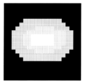
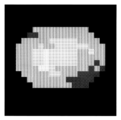
- FIG. 5 is a schematic diagram showing an example of the first phase image obtained from the template data 1.
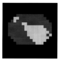
- the number of pixels is coarsened by 20 ⁇ 20 (the same applies to FIGS. 6 and 7 described later).
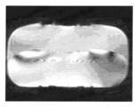
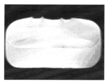
- a pixel having a larger pixel value is whiter (a luminance level is higher) and a pixel having a smaller pixel value is blackened (the same applies to FIGS. 6, 7, 8, and 9 described later).
- a first phase image as a substantially symmetric magnetic field map is obtained.
- FIG. 6 is a schematic diagram showing an example of the second phase image obtained from the template data 2. As shown in FIG. 6, a second phase image having a lower symmetry than that of the template shot 1 is obtained from the template shot 2.
- FIG. 7 is a schematic diagram showing an example of a difference image (magnetic field correction map) obtained based on the equation (3) using the first phase image and the second phase image. As shown in FIG. 7, the phase difference appears as the gradient of the pixel value by taking the difference between the phase images obtained from the template shots 1 and 2, respectively.
- FIG. 8 shows an example of an image obtained by imaging a uniform phantom without correcting the static magnetic field inhomogeneity by the magnetic field correction map before the main scan.
- FIG. 9 shows an example of an image obtained by imaging the same phantom as in FIG. 8 after correcting the static magnetic field inhomogeneity by the magnetic field correction map before the main scan.
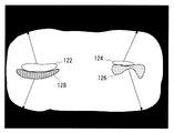
- FIG. 10 is a schematic diagram for explaining the difference between the case where the correction by the magnetic field correction map is not performed (FIG. 8) and the case where the correction is performed (FIG. 9).
- FIG. 10 shows the four distorted areas extracted from the image of FIG. 8, which are distorted areas 122, 124, 126, and 128.
- strain regions 122, 124, 126, and 128 appear as shown in a comparison between FIG. 8 and FIG.
- the distortion region 122 is on the upper left outer edge of the phantom
- the distortion region 124 is on the upper right outer edge of the phantom
- the distortion region 126 is on the lower right side of the phantom.
- the strain area 128 has moved to the outer edge on the lower left side of the phantom.
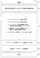
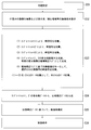
- FIG. 11 is a flowchart showing a flow of operations of the MRI apparatus 20 in the first embodiment.
- the operation of the MRI apparatus 20 will be described according to the step numbers shown in FIG.
- Step S1 The MPU 86 (see FIG. 2) performs initial setting of the MRI apparatus 20 based on the imaging conditions input to the MRI apparatus 20 via the input apparatus 62. In this initial setting, the provisional center frequency of the RF pulse when the positioning image is captured is set.
- Step S2 The sequence controller 56 drives a bed control system (not shown) and moves the bed 32 (see FIG. 1) so that the imaging region of the subject P is positioned at the center of the magnetic field in the gantry serving as the imaging space.
- the imaging region means which part of the subject P such as the head, chest, abdomen, waist, and legs is imaged as an imaging region.
- the MRI apparatus 20 transmits an RF pulse for collecting data of the positioning image and detects the MR signal by the RF receiver 48.
- the RF receiver 48 performs predetermined signal processing on the MR signal, generates raw data which is a digitized MR signal, and inputs this to the sequence controller 56.
- the sequence controller 56 inputs the raw data of the MR signal to the image reconstruction unit 90, and the image reconstruction unit 90 performs predetermined processing on the raw data to generate the image data of the positioning image, which is generated in the image database. 94.
- the image processing unit 96 performs predetermined image processing on the input image data, and the storage device 66 stores the image data of the positioning image after the image processing. Thereafter, the display control unit 98 displays a positioning image on the display device 64 in accordance with an instruction from the MPU 86, and an imaging condition such as a region of interest is set based on the positioning image.
- Step S3 The MRI apparatus 20 executes two types of template shots for generating phase correction data and magnetic field correction data as a pre-scan according to the following flow ⁇ 1> to ⁇ 4>, and then performs a target image. Data collection (main scan) is executed.
- template shots 1 and 2 are performed on the spatially identical area and the same area as the imaging area of the main scan.
- the MPU 86 sets the same pulse sequence of the main scan set based on the imaging conditions input up to step S2 as the pulse sequence of the template shot 1 (see FIG. 3). Next, the MPU 86 inputs the pulse sequence of the template shot 1 to the sequence controller 56, and commands acquisition start.
- the MRI apparatus 20 transmits an RF pulse for data collection in accordance with the pulse sequence of the template shot 1 and detects the MR signal by the RF receiver 48.
- the sequence controller 56 inputs the raw data of the MR signal detected and generated by the RF receiver 48 to the image reconstruction unit 90.
- the image reconstruction unit 90 arranges this raw data as k-space data of the template shot 1 in the k-space formed in the k-space database 92.
- the MPU 86 sets, as the template shot 2 pulse sequence, a phase encoding step pulse and a timing at which application of the readout direction gradient magnetic field Gro is delayed from the template shot 1. Further, the polarities of the gradient magnetic fields Gro in the reading directions of the template shots 1 and 2 at the timing when the phase encoding step is zero are reversed. Details of the differences between the template shots 1 and 2 have already been described with reference to FIG.
- the MPU 86 inputs the pulse sequence of the template shot 2 to the sequence controller 56 and commands the start of collection.
- the k-space data of the template shot 2 is arranged in the k-space formed in the k-space database 92 in the same manner as (1) above.
- the correction unit 100 acquires the k-space data of the template shots 1 and 2 from the k-space database 92 of the image reconstruction unit 90, respectively, and the first phase image that is the phase image of the template 1 and the template shot And a second phase image, which is a second phase image.
- the correction unit 100 uses the first phase image and the second phase image to generate a difference image according to the equation (3), and inputs this difference image to the MPU 86 as a magnetic field correction map.
- the first and second phase images and the difference image generation method are as described above.
- MR signals for the main scan are collected according to the set imaging conditions.
- the MPU 86 calculates an offset magnetic field that makes the static magnetic field uniform by offsetting the magnetic field inhomogeneity indicated by the magnetic field correction map. And MPU86 controls each part via the sequence controller 56 so that an offset magnetic field may be superimposed and applied to a static magnetic field.
- the second and higher order components in the non-uniform component of the static magnetic field can be shimmed by adjusting the supply current to the shim coil 24, for example.
- the primary component in the non-uniform component of the static magnetic field can be shimmed by adjusting the supply currents to the X-axis, Y-axis, and Z-axis gradient magnetic field coils 26x, 26y, and 26z, for example.
- a static magnetic field is formed in the imaging space by the static magnetic field magnet 22 excited by the static magnetic field power supply 40.
- the MPU 86 inputs imaging conditions including a pulse sequence of the main scan to the sequence controller 56.
- the sequence controller 56 drives the gradient magnetic field power supply 44, the RF transmitter 46, and the RF receiver 48 in accordance with the input pulse sequence, so that the slice selection direction gradient magnetic field Gss, the phase encode direction gradient magnetic field Gpe, and the read direction gradient magnetic field Gro. Are formed in the imaging region, and an RF signal is generated from the RF coil 28.
- the supply current from the gradient magnetic field power supply 44 to the X-axis, Y-axis, and Z-axis gradient magnetic field coils 26x, 26y, and 26z is superimposed with the amount of generation of the offset magnetic field, so that the static magnetic field is substantially uniformized.
- the MR signal generated by the nuclear magnetic resonance in the subject P is received by the RF coil 28 and detected by the RF receiver 48.
- the RF receiver 48 performs the predetermined signal processing described above on the detected MR signal to generate raw data of the MR signal, and inputs this to the sequence controller 56.
- the sequence controller 56 inputs the raw data to the image reconstruction unit 90, and the image reconstruction unit 90 arranges the raw data as k-space data in the k-space formed in the k-space database 92.
- the MRI apparatus 20 collects data for all slices by using the above processes ⁇ 1> to ⁇ 4> as data collection for one slice.
- the correction unit 100 calculates phase correction data for all slices.
- the correction unit 100 inputs each phase correction data to the image reconstruction unit 90 in association with each slice for which each phase correction data is calculated.
- the correction unit 100 calculates each frequency integral value of each data obtained by performing one-dimensional Fourier inverse transformation on each center line of the real part and the imaginary part of the k-space data of the template data 1, and then performs the inverse as described above.
- the phase angle Ph1 of the template data 1 is calculated using the tangent.
- the correction unit 100 calculates the phase angle Ph2 of the template data 2, and sets the phase angles Ph1 and ph2 as phase correction data of slices corresponding to the template data 1 and 2.
- the image reconstruction unit 90 reconstructs image data for each slice by taking k-space data from the k-space database 92 and subjecting it to image reconstruction processing including Fourier transform.
- the image reconstruction unit 90 performs correction to remove the influence of the phase error included in the MR signal, using the phase correction data calculated separately for each slice.
- the processing up to the generation of phase correction data is different from the conventional one, the phase error correction processing after generating the phase correction data may be the same as that of the conventional technology (see Patent Document 2 etc.). Description is omitted.
- the image reconstruction unit 90 generates image data of all slices as described above, and stores these in the image database 94.
- the image processing unit 96 takes in image data from the image database 94, performs predetermined image processing on the image data, generates two-dimensional display image data, and stores the display image data in the storage device 66.
- Step S6 The display control unit 98 acquires display image data from the storage device 66 according to the control of the MPU 86, and causes the display device 64 to display an image indicated by the display image data.
- the above is the description of the operation of the MRI apparatus 20 of the first embodiment.
- template shots 1 and 2 including the application of the phase encoding direction gradient magnetic field corresponding to each echo and the echo generation start timings being shifted from each other are executed before the main scan.
- the correction for equalizing the static magnetic field in the main scan and the correction of the phase error after collecting the MR signal of the main scan are performed at once. Can be done automatically.
- the correction for homogenizing the static magnetic field is first performed based on the magnetic field correction map, and after the MR signals of the main scan are collected, the phase error is corrected based on the phase correction data. That is, the MR signal of the main scan is collected from an imaging region to which a static magnetic field that is well uniformized based on the magnetic field correction map is applied. Therefore, the accuracy of correcting the phase error can be improved.
- the magnetic field correction data is generated based on the collected data from the same section as the imaging slice and the non-uniformity of the static magnetic field is corrected for each slice, the static magnetic field correction effect is enhanced.
- the MRI apparatus of the second and third embodiments is the same as the MRI apparatus 20 of the first embodiment as the apparatus configuration.
- correction for equalizing the static magnetic field based on the magnetic field correction map is not performed, but only phase error correction is performed.
- the second embodiment will be described with a focus on differences from the first embodiment.
- FIG. 12 is a timing chart showing an example of a pulse sequence of main scan and template shots 1 and 2 'as a spin-echo single shot EPI in the second embodiment. 12, the format of the horizontal axis and the like is the same as in FIG. 3, and the upper main scan and the middle template shot 1 in FIG. 12 are the main scan and template shot 1 of the first embodiment, respectively. Is the same.
- the generation timing of the MR signal corresponding to the phase encoding step of zero is the same as that in the template shot 1.
- the generation timing of the MR signal corresponding to zero in the phase encoding step is shifted in template shots 1 and 2, but the magnetic field correction map is not generated in the second embodiment.
- the area of the pre-pulse of the phase encode gradient magnetic field Gpe (the absolute value of the time integral value of the intensity) is equal to the combined area of the first four phase encode step pulses. That is, in the template shot 2 ', the MR signal collected fifth in time corresponds to the phase encoding step zero, and the intensity of this MR signal is maximized.
- the polarity of the readout direction gradient magnetic field Gro at this timing is negative in the template shot 1 and positive in the template shot 2 '. This is because in order to obtain the phase correction data, it is desired to reverse the polarities of the read direction gradient magnetic field Gro at the timing when the phase encoding step is zero in the template shots 1 and 2 ′.
- phase correction data can be generated based on the same principle as in the first embodiment.
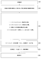
- FIG. 13 is a flowchart showing an operation flow of the MRI apparatus 20 in the second embodiment.
- the operation of the MRI apparatus 20 of the second embodiment will be described according to the step numbers shown in FIG.
- Step S21 Similar to step S1 of the first embodiment, the initial setting of the MRI apparatus 20 is performed.
- Step S22 As in step S2 of the first embodiment, image data of a positioning image is generated, and this is displayed on the display device 64, and imaging conditions such as a region of interest are set.
- Step S23 The MRI apparatus 20 executes main scan after executing two types of template shots for generating phase correction data as pre-scans according to the following flow ⁇ 1> to ⁇ 3>.
- the template shots 1 and 2 ′ are respectively performed on the same area as the imaging area of the main scan, which are spatially the same area.
- the MRI apparatus 20 executes the template shot 1 pulse sequence in the same manner as ⁇ 1> in step S3 of the first embodiment.
- the k-space data of the template shot 1 is arranged (stored) in the k-space formed in the k-space database 92.
- the MPU 86 After setting the pulse sequence of the template shot 2 'described above, the MPU 86 inputs this pulse sequence to the sequence controller 56 and commands the start of collection. As a result, the k-space data of the template shot 2 ′ is arranged in the k-space formed in the k-space database 92.
- MR signals for the main scan are collected according to the set imaging conditions without correcting the static magnetic field homogenization based on the magnetic field correction map.
- the specific operation of MR signal acquisition is the same as ⁇ 4> in step S3 of the first embodiment except that the magnetic field correction map is not used.
- the MRI apparatus 20 collects data for all slices by using the above processes ⁇ 1> to ⁇ 3> as data collection for one slice.
- the correction unit 100 uses the k-space data of the template shots 1 and 2 'to calculate phase correction data for all slices, as in step S4 of the first embodiment.
- the correction unit 100 inputs the calculated phase correction data to the image reconstruction unit 90 in association with each slice to be calculated.
- Step S25 As in step S5 of the first embodiment, the image reconstruction unit 90 corrects the phase error included in the MR signal based on the phase correction data for each slice, and the image data of each slice. Reconfigure. Thereafter, display image data is generated and stored in the storage device 66, as in step S5 of the first embodiment.
- Step S26 Similar to step S6 of the first embodiment, the image data for display is displayed.
- the above is the description of the operation of the MRI apparatus 20 of the second embodiment.
- the phase error in EPI can be reduced on the same principle as in the first embodiment.
- the phase encoding direction gradient magnetic field Gpe is not applied in the template shot for reducing the phase error.
- FIG. 14 is a timing diagram showing an example of a pulse sequence of template shots 1, 2, and 3 as a spin echo single shot EPI in the third embodiment.
- the format such as the horizontal axis is the same as in FIG.
- the pulse sequence of the main scan of the third embodiment is not shown because it is the same as the main scan of the first embodiment and the template shot 1 of the third embodiment.
- the template shot 1 (TEMPLATE SHOT 1) shown in the upper part of FIG. 14 is the same as the template shot 1 of the first embodiment.
- the template shot 2 '(TEMPLATE SHOT 2') shown in the middle part of Fig. 14 is the same as the template shot 2 'of the second embodiment.
- phase correction data is generated and the phase error is corrected as in the second embodiment.
- the template shot 3 (TEMPLATE SHOT 3) shown in the lower part of FIG. 14 is for generating a magnetic field correction map.
- a magnetic field correction map is generated as in the first embodiment, and the static magnetic field uniformity is corrected.
- the generation timing of the MR signal corresponding to the phase encoding step of zero is delayed from the template shot 1 by 1 time of the Gro inversion interval.
- delay is based on, for example, the start of applying a pre-pulse of the phase encoding gradient magnetic field Gpe.
- the area of the pre-pulse of the phase encoding gradient magnetic field Gpe (the absolute value of the time integral value of the intensity) is equal to the combined area of the first five phase encoding step pulses. That is, in template shot 3, the MR signal collected sixth in time is arranged in the center line of the k space corresponding to the phase encoding step zero, and the intensity of this MR signal is maximized.
- This timing corresponds to the effective echo time (EFFECTIVE ECHO TIME) indicated by the vertical broken line in FIG. 14 in the template shot 1, but is delayed by one echo in the template shot 3 from the template shot 1.
- the polarity of the read direction gradient magnetic field Gro at the generation timing of the MR signal corresponding to the phase encoding step of zero is negative in both template shots 1 and 3 (see FIG. 14). That is, in the first embodiment, since the template shot 2 is used to generate both the phase correction data and the magnetic field correction map, the polarity of the readout direction gradient magnetic field Gro at this timing is reversed. This is because it is desired to generate phase correction data.
- the template shot 3 of the third embodiment is not used for generating phase correction data.
- attention is paid only to the generation of the magnetic field correction map, it is not necessary to reverse the polarities of the read-direction gradient magnetic field Gro at the timing of the phase encoding step zero in the two template shots.
- FIG. 15 is a flowchart showing a flow of operations of the MRI apparatus 20 in the third embodiment. The operation of the MRI apparatus 20 according to the third embodiment will be described below according to the step numbers shown in FIG.
- Step S31 Similar to step S1 of the first embodiment, the initial setting of the MRI apparatus 20 is performed.
- Step S32 As in step S2 of the first embodiment, image data of a positioning image is generated, displayed on the display device 64, and imaging conditions such as a region of interest are set.
- Step S33 The MRI apparatus 20 executes the main scan after executing three types of template shots for generating the phase correction data and the magnetic field correction map as a pre-scan according to the following flow ⁇ 1> to ⁇ 5>. To do. Note that the template shots 1, 2 ′, and 3 are respectively performed on the same area as the imaging area of the main scan.
- the MRI apparatus 20 executes the template shot 1 pulse sequence in the same manner as ⁇ 1> in step S3 of the first embodiment.
- the k-space data of the template shot 1 is arranged (stored) in the k-space formed in the k-space database 92.
- the MRI apparatus 20 executes the pulse sequence of the template shot 2 'as in ⁇ 2> of step S23 of the second embodiment.
- the k-space data of the template shot 2 ′ is arranged (stored) in the k-space formed in the k-space database 92.
- the MPU 86 After setting the template shot 3 pulse sequence described above, the MPU 86 inputs this pulse sequence to the sequence controller 56 and commands the start of collection. Thereby, the k space data of the template shot 3 is arranged in the k space formed in the k space database 92.
- the correction unit 100 acquires the k-space data of the template shots 1 and 3 from the k-space database 92 of the image reconstruction unit 90, respectively.
- the correction unit 100 generates a first phase image that is a phase image of the template shot 1 and a second phase image that is a phase image of the template shot 3.
- the correction unit 100 uses the first phase image and the second phase image to generate a difference image according to equation (3) as described above, and inputs this difference image to the MPU 86 as a magnetic field correction map.
- step S3 of the first embodiment the correction for homogenizing the static magnetic field is performed based on the magnetic field correction map, and then the MR of the main scan according to the set imaging conditions Signal collection is performed.
- the MRI apparatus 20 collects data for all slices by using the above processes ⁇ 1> to ⁇ 5> as data collection for one slice.
- the correction unit 100 calculates the phase correction data for all slices by using the k-space data of the template shots 1 and 2 'as in step S4 of the first embodiment.
- the correction unit 100 inputs the calculated phase correction data to the image reconstruction unit 90 in association with the slice to be calculated.
- Step S35 Similar to step S5 of the first embodiment, the image reconstruction unit 90 corrects the phase error included in the MR signal based on the phase correction data for each slice, and the image data of each slice. Reconfigure. Thereafter, display image data is generated and stored in the storage device 66, as in step S5 of the first embodiment.
- Step S36 As in step S6 of the first embodiment, the image data for display is displayed.
- the above is the description of the operation of the MRI apparatus 20 of the third embodiment.
- the effect similar to 1st Embodiment is acquired.
- the pulse sequences of the template shots 1, 2, 2'3 are the same except for the timing of application of the phase encoding step pulse and the readout direction gradient magnetic field Gro. This is because, if the conditions are changed, it may be difficult to extract only the phase difference. The same applies to the following supplementary items [2] and [3].
- each template shot 1, 2, 2 is performed.
- '3 is preferably performed before the main scan.
- the magnetic field correction map is not generated before the main scan, the correction of the static magnetic field uniformity based on the magnetic field correction map cannot be executed.
- any one of the template shots 1, 2, 2 'and 3 may be performed first.
- the phase error is corrected based on the data obtained from the echo signal group (MR signal group) collected in the main scan without performing the template shot 1. You may go.
- the phase correction data is calculated by the equation (1) using the MR signal of the main scan as the template data 1.
- the template shot 1 can be omitted, so that the imaging time can be shortened.
- the main scan is executed after the static magnetic field is made uniform using the shim coil 24 or the like based on the magnetic field correction map.
- the following processing is performed instead of the static magnetic field homogenization using the shim coil 24 or the like.
- the MR signal group collected in the main scan is set as the template data 1, and based on this and the template data 2, the magnetic field correction map is also generated in step S4 after the main scan. Then, a distortion amount is calculated based on the magnetic field correction map, and distortion correction (pixel movement) can be performed on the image data reconstructed by performing phase correction on the MR signal.
- the template shots 1 and 3 are omitted, and a modified example using the data obtained by the main scan may be the same as the modified example of the first embodiment.
- FIG. 16 is a timing chart showing an example of a pulse sequence of main scan and template shots 1 ′′ and 2 ′′ in a single shot EPI of FID type (free induction decay signal: Free Induction Decay).
- the upper stage, the middle stage, and the lower stage show the pulse sequences of the main scan, template shot 1 ", and template shot 2", respectively.
- the application start of the read direction gradient magnetic field Gro is shifted by twice the echo interval in the template shots 1 ′ and 2 ′, but this is only an example and may be shifted by a natural multiple other than double.
- the imaging area may be a slab.
- the image data to be generated may be image data for a two-dimensional image or three-dimensional volume data.
- the RF receiver 48 exists outside the gantry including the static magnetic field magnet 22, the shim coil 24, the gradient magnetic field coil unit 26, and the RF coil 28 has been described (see FIG. 1).
- the embodiment of the present invention is not limited to such an aspect.
- the RF receiver 48 may be included in the gantry.
- an electronic circuit board corresponding to the RF receiver 48 is disposed in the gantry. Then, the MR signal converted from the electromagnetic wave to the analog electric signal by the receiving RF coil may be amplified by the preamplifier in the electronic circuit board, output as a digital signal outside the gantry, and input to the sequence controller 56. .
- the preamplifier in the electronic circuit board For output to the outside of the gantry, for example, it is desirable to transmit as an optical digital signal using an optical communication cable, because the influence of external noise is reduced.
- the imaging function according to claim 1, wherein the static magnetic field magnet 22, the shim coil 24, the gradient magnetic field coil 26, the RF coil 28, and the entire control device 30 collect MR signals in the main scan based on the EPI sequence. It is an example of a data collection part.
- the function of the magnetostatic field magnet 22, the shim coil 24, the gradient magnetic field coil 26, the RF coil 28, and the control device 30 to collect the MR signals by executing the template shot 1 is an example of the first collecting unit according to claim. is there.
- the phase correction data is calculated by the equation (1) using the MR signal of the main scan as the template data 1 without executing the template shot 1, the static magnetic field magnet 22, the shim coil 24, the gradient magnetic field coil 26, the RF coil 28.
- the function of the entire control device 30 to collect the MR signals of the main scan is an example of a first acquisition unit recited in the claims.
- the function that the whole of the static magnetic field magnet 22, the shim coil 24, the gradient magnetic field coil 26, the RF coil 28, and the control device 30 executes the template shot 2 (or 2 ′) and collects MR signals is the second aspect of the invention. It is an example of a collection part.
- the function that the whole of the static magnetic field magnet 22, the shim coil 24, the gradient magnetic field coil 26, the RF coil 28, and the control device 30 executes the template shot 3 and collects MR signals is an example of the third collection unit according to claim. is there.
- the function of the correction unit 100 that generates the phase correction data and the magnetic field correction map, the function of the image reconstruction unit 90 that corrects the phase error based on the phase correction data, and the uniform static magnetic field before the main scan based on the magnetic field correction map The overall functions of the gradient magnetic field power supply 44, the gradient magnetic field coil 26, and the control device 30 that perform magnetic field correction for conversion to one another are examples of the correction unit described in the claims.
Landscapes
- Physics & Mathematics (AREA)
- Health & Medical Sciences (AREA)
- General Health & Medical Sciences (AREA)
- Nuclear Medicine, Radiotherapy & Molecular Imaging (AREA)
- Radiology & Medical Imaging (AREA)
- Engineering & Computer Science (AREA)
- Signal Processing (AREA)
- High Energy & Nuclear Physics (AREA)
- Condensed Matter Physics & Semiconductors (AREA)
- General Physics & Mathematics (AREA)
- Magnetic Resonance Imaging Apparatus (AREA)
Priority Applications (3)
| Application Number | Priority Date | Filing Date | Title |
|---|---|---|---|
| CN201180001735.0A CN102438518B (zh) | 2010-08-11 | 2011-08-02 | 磁共振成像装置及磁共振成像方法 |
| EP11784405.0A EP2457503B1 (en) | 2010-08-11 | 2011-08-02 | Magnetic resonance imaging device and magnetic resonance imaging method |
| US13/320,766 US8890525B2 (en) | 2010-08-11 | 2011-08-02 | Magnetic resonance imaging apparatus and magnetic resonance imaging method |
Applications Claiming Priority (2)
| Application Number | Priority Date | Filing Date | Title |
|---|---|---|---|
| JP2010180389 | 2010-08-11 | ||
| JP2010-180389 | 2010-08-11 |
Publications (1)
| Publication Number | Publication Date |
|---|---|
| WO2012020720A1 true WO2012020720A1 (ja) | 2012-02-16 |
Family
ID=45567687
Family Applications (1)
| Application Number | Title | Priority Date | Filing Date |
|---|---|---|---|
| PCT/JP2011/068014 Ceased WO2012020720A1 (ja) | 2010-08-11 | 2011-08-02 | 磁気共鳴イメージング装置および磁気共鳴イメージング方法 |
Country Status (5)
| Country | Link |
|---|---|
| US (1) | US8890525B2 (cg-RX-API-DMAC7.html) |
| EP (1) | EP2457503B1 (cg-RX-API-DMAC7.html) |
| JP (1) | JP5835989B2 (cg-RX-API-DMAC7.html) |
| CN (1) | CN102438518B (cg-RX-API-DMAC7.html) |
| WO (1) | WO2012020720A1 (cg-RX-API-DMAC7.html) |
Families Citing this family (27)
| Publication number | Priority date | Publication date | Assignee | Title |
|---|---|---|---|---|
| DE102011005728B4 (de) * | 2011-03-17 | 2012-10-31 | Siemens Aktiengesellschaft | Verzeichnungsfreies Bestimmen von Magnetresonanzdaten |
| DE102011006230B4 (de) * | 2011-03-28 | 2013-01-24 | Siemens Aktiengesellschaft | Pixelweise Korrektur einer Phaseninformation in MR-Bildern unter Verwendung eines Navigatorsignals |
| JP5925529B2 (ja) * | 2011-03-31 | 2016-05-25 | 株式会社東芝 | 磁気共鳴イメージング装置 |
| WO2013118117A1 (en) * | 2012-02-08 | 2013-08-15 | Anatech Advanced Nmr Algorithms Technologies Ltd | Method and system for inspection of composite material components |
| DE102012208425B4 (de) | 2012-05-21 | 2013-12-12 | Siemens Aktiengesellschaft | Kontinuierliches Korrigieren von Phasenfehlern einer multidimensionalen, ortsselektiven Magnetresonanz-Messsequenz |
| CN102768347B (zh) * | 2012-08-09 | 2014-07-09 | 厦门大学 | 核磁共振波谱仪上缩减相位编码数快速三维梯度匀场方法 |
| CN102890255B (zh) * | 2012-10-19 | 2015-07-29 | 浙江大学 | 一种用于缩短回波时间的由内而外平面回波成像方法 |
| CN104035059B (zh) * | 2013-03-06 | 2015-05-13 | 上海联影医疗科技有限公司 | 平面回波成像序列图像的重建方法 |
| JP6058477B2 (ja) * | 2013-06-14 | 2017-01-11 | 東芝メディカルシステムズ株式会社 | 磁気共鳴イメージング装置 |
| JP6495057B2 (ja) * | 2015-03-16 | 2019-04-03 | キヤノンメディカルシステムズ株式会社 | Mri装置及び撮像時間短縮方法 |
| JP2016198392A (ja) | 2015-04-13 | 2016-12-01 | 東芝メディカルシステムズ株式会社 | 磁気共鳴イメージング装置 |
| CN107205718B (zh) * | 2015-12-30 | 2020-06-05 | 深圳先进技术研究院 | 一种聚焦超声位移成像方法及装置 |
| KR101819030B1 (ko) | 2016-02-17 | 2018-01-16 | 삼성전자주식회사 | 자기 공명 영상 장치 및 자기 공명 영상 장치를 위한 방법 |
| US10605883B2 (en) * | 2016-04-22 | 2020-03-31 | Sunnybrook Research Institute | System and method for producing distortion free magnetic resonance images using dual-echo echo-planar imaging |
| KR20180067442A (ko) * | 2016-12-12 | 2018-06-20 | 지멘스 헬스케어 게엠베하 | 가속형 자기 공명 촬영 |
| JP6283134B2 (ja) * | 2017-03-07 | 2018-02-21 | キヤノンメディカルシステムズ株式会社 | 磁気共鳴イメージング装置及び画像処理装置 |
| EP3441781A1 (de) * | 2017-08-11 | 2019-02-13 | Siemens Healthcare GmbH | Beschleunigte magnetresonanz-messung |
| US12156713B2 (en) | 2018-09-17 | 2024-12-03 | The Methodist Hospital | Signal isolation magnetic resonance image (SIMRI) and methods thereof |
| CN109741409A (zh) * | 2018-11-30 | 2019-05-10 | 厦门大学 | 回波平面成像涡流伪影的无参考扫描校正方法 |
| CN109917315B (zh) | 2019-04-30 | 2021-09-28 | 上海联影医疗科技股份有限公司 | 磁共振成像扫描方法、装置、计算机设备和存储介质 |
| WO2020238818A1 (en) | 2019-05-24 | 2020-12-03 | Shanghai United Imaging Healthcare Co., Ltd. | Imaging systems and methods |
| EP3796023A1 (de) * | 2019-09-18 | 2021-03-24 | Siemens Healthcare GmbH | Verbessertes magnetresonanz-dixon-verfahren |
| EP3865892A1 (en) * | 2020-02-17 | 2021-08-18 | Koninklijke Philips N.V. | Iterative reconstruction of gradient echo magnetic resonance images |
| CN112731235B (zh) * | 2020-12-09 | 2024-04-19 | 中国科学院深圳先进技术研究院 | 一种磁共振化学交换饱和转移成像方法以及相关设备 |
| CN115113122B (zh) * | 2021-03-18 | 2025-09-12 | 佳能医疗系统株式会社 | 图像处理装置以及图像处理方法 |
| CN115469254B (zh) * | 2021-05-18 | 2025-04-25 | 上海联影医疗科技股份有限公司 | 一种磁共振定量成像方法 |
| CN115040107B (zh) * | 2022-05-06 | 2025-11-18 | 东软医疗系统股份有限公司 | 基于并行成像的成像方法及装置、存储介质、终端 |
Citations (6)
| Publication number | Priority date | Publication date | Assignee | Title |
|---|---|---|---|---|
| JPH09276243A (ja) | 1996-04-16 | 1997-10-28 | Toshiba Corp | 磁気共鳴診断装置 |
| JPH11290289A (ja) * | 1998-04-13 | 1999-10-26 | Technol Res Assoc Of Medical & Welfare Apparatus | 核磁気共鳴を用いた検査装置 |
| JP2001238866A (ja) * | 2000-03-01 | 2001-09-04 | Hitachi Ltd | 磁気共鳴イメージング装置 |
| JP2005319074A (ja) * | 2004-05-10 | 2005-11-17 | Hitachi Medical Corp | 磁気共鳴イメージング装置 |
| JP2006255046A (ja) | 2005-03-16 | 2006-09-28 | Hamano Life Science Research Foundation | 磁気共鳴映像法および画像処理装置 |
| JP2007159718A (ja) * | 2005-12-12 | 2007-06-28 | Toshiba Corp | 磁気共鳴イメージング装置および画像補正評価方法 |
Family Cites Families (16)
| Publication number | Priority date | Publication date | Assignee | Title |
|---|---|---|---|---|
| US4885542A (en) * | 1988-04-14 | 1989-12-05 | The Regents Of The University Of California | MRI compensated for spurious NMR frequency/phase shifts caused by spurious changes in magnetic fields during NMR data measurement processes |
| US4937526A (en) * | 1988-11-23 | 1990-06-26 | Mayo Foundation For Medical Education And Research | Adaptive method for reducing motion and flow artifacts in NMR images |
| US5270654A (en) * | 1991-07-05 | 1993-12-14 | Feinberg David A | Ultra-fast multi-section MRI using gradient and spin echo (grase) imaging |
| JP3152690B2 (ja) | 1991-09-06 | 2001-04-03 | 株式会社東芝 | 磁気共鳴映像装置 |
| JPH09253070A (ja) | 1996-03-26 | 1997-09-30 | Hitachi Ltd | 核磁気共鳴を用いた検査装置 |
| US5810727A (en) * | 1996-04-24 | 1998-09-22 | U.S. Philips Corporation | Method of and device for the imaging of objects by means of magnetic resonance |
| US5672969A (en) * | 1996-04-25 | 1997-09-30 | General Electric Company | Reduction of Nyquist ghost artifacts in oblique echo planar imaging |
| US6249595B1 (en) * | 1998-01-22 | 2001-06-19 | General Electric Company | Iterative reconstruction for EPI |
| US6160397A (en) * | 1998-12-30 | 2000-12-12 | General Electric Company | Fast spin echo prescan for magnetic resonance imaging systems |
| WO2000072753A1 (en) * | 1999-05-31 | 2000-12-07 | Hitachi Medical Corporation | Magnetic resonance imaging method and device |
| US6700374B1 (en) * | 2000-03-29 | 2004-03-02 | Koninklijke Philips Electronics, N.V. | EPI calibration method to minimize ghosting in reconstructed images |
| JP4619674B2 (ja) * | 2004-03-24 | 2011-01-26 | 株式会社東芝 | 磁気共鳴イメージング装置 |
| US7102352B2 (en) * | 2004-09-30 | 2006-09-05 | General Electric Company | Method and system for image artifact reduction using nearest-neighbor phase correction for echo planar imaging |
| US7098662B2 (en) * | 2004-09-30 | 2006-08-29 | General Electric Company | Method and system of MR imaging with variable readout gradient filtering |
| US7259557B2 (en) * | 2005-10-19 | 2007-08-21 | General Electric Company | Method and apparatus of echo planar imaging with real-time determination of phase correction coefficients |
| US7622924B2 (en) * | 2007-06-12 | 2009-11-24 | General Electric Company | Method and apparatus for k-space and hybrid-space based image reconstruction for parallel imaging and artifact correction |
-
2011
- 2011-08-01 JP JP2011168597A patent/JP5835989B2/ja active Active
- 2011-08-02 EP EP11784405.0A patent/EP2457503B1/en active Active
- 2011-08-02 US US13/320,766 patent/US8890525B2/en active Active
- 2011-08-02 CN CN201180001735.0A patent/CN102438518B/zh active Active
- 2011-08-02 WO PCT/JP2011/068014 patent/WO2012020720A1/ja not_active Ceased
Patent Citations (6)
| Publication number | Priority date | Publication date | Assignee | Title |
|---|---|---|---|---|
| JPH09276243A (ja) | 1996-04-16 | 1997-10-28 | Toshiba Corp | 磁気共鳴診断装置 |
| JPH11290289A (ja) * | 1998-04-13 | 1999-10-26 | Technol Res Assoc Of Medical & Welfare Apparatus | 核磁気共鳴を用いた検査装置 |
| JP2001238866A (ja) * | 2000-03-01 | 2001-09-04 | Hitachi Ltd | 磁気共鳴イメージング装置 |
| JP2005319074A (ja) * | 2004-05-10 | 2005-11-17 | Hitachi Medical Corp | 磁気共鳴イメージング装置 |
| JP2006255046A (ja) | 2005-03-16 | 2006-09-28 | Hamano Life Science Research Foundation | 磁気共鳴映像法および画像処理装置 |
| JP2007159718A (ja) * | 2005-12-12 | 2007-06-28 | Toshiba Corp | 磁気共鳴イメージング装置および画像補正評価方法 |
Non-Patent Citations (2)
| Title |
|---|
| A. JESMANOWICZ: "Phase Correction for EPI Using Internal Reference Line", PROCEEDINGS OF SMR, 1995 |
| A. JESMANOWICZ: "Self-Correcting EPI Reconstruction Algorithm;", PROCEEDINGS OF SMR, 1995 |
Also Published As
| Publication number | Publication date |
|---|---|
| EP2457503A1 (en) | 2012-05-30 |
| CN102438518B (zh) | 2015-06-10 |
| US8890525B2 (en) | 2014-11-18 |
| EP2457503B1 (en) | 2019-07-17 |
| JP5835989B2 (ja) | 2015-12-24 |
| US20120146640A1 (en) | 2012-06-14 |
| CN102438518A (zh) | 2012-05-02 |
| JP2012055684A (ja) | 2012-03-22 |
| EP2457503A4 (en) | 2014-12-31 |
Similar Documents
| Publication | Publication Date | Title |
|---|---|---|
| JP5835989B2 (ja) | 磁気共鳴イメージング装置および磁気共鳴イメージング方法 | |
| JP6058477B2 (ja) | 磁気共鳴イメージング装置 | |
| CN101627910B (zh) | 磁共振成像装置及磁共振成像方法 | |
| JP6809819B2 (ja) | 磁気共鳴イメージング装置及び画像処理装置 | |
| JP5868160B2 (ja) | 磁気共鳴イメージング装置 | |
| JP4619674B2 (ja) | 磁気共鳴イメージング装置 | |
| US9476959B2 (en) | MRI ghosting correction using unequal magnitudes ratio | |
| US20140210471A1 (en) | Method and control device for operating a magnetic resonance system | |
| US9606210B2 (en) | Magnetic resonance imaging apparatus and magnetic resonance imaging method | |
| CN102342832B (zh) | 磁共振成像方法、磁共振成像装置及其控制装置 | |
| JP2014158535A (ja) | 磁気共鳴イメージング装置 | |
| CN102621510A (zh) | 用于抑制mr成像中伪影的系统 | |
| WO2012124375A1 (ja) | 磁気共鳴イメージング装置 | |
| CN108318843A (zh) | 磁共振成像装置以及磁共振成像方法 | |
| JP5666779B2 (ja) | 磁気共鳴イメージング装置 | |
| WO2020173688A1 (en) | Epi mr imaging with distortion correction | |
| CN103747728A (zh) | 磁共振成像装置以及磁共振成像方法 | |
| WO2014157237A1 (ja) | 磁気共鳴イメージング装置 | |
| JP2009160051A (ja) | 磁気共鳴イメージング装置 | |
| JP2013017811A (ja) | 磁気共鳴イメージング装置 | |
| JP7722899B2 (ja) | 磁気共鳴イメージング装置及び磁気共鳴イメージングプログラム | |
| JP2016154849A (ja) | 磁気共鳴イメージング装置 | |
| JP2001340316A (ja) | 磁気共鳴イメージング装置 | |
| JP5395619B2 (ja) | 磁気共鳴イメージング装置 | |
| JP2016040024A (ja) | 磁気共鳴イメージング装置 |
Legal Events
| Date | Code | Title | Description |
|---|---|---|---|
| WWE | Wipo information: entry into national phase |
Ref document number: 201180001735.0 Country of ref document: CN |
|
| WWE | Wipo information: entry into national phase |
Ref document number: 13320766 Country of ref document: US |
|
| WWE | Wipo information: entry into national phase |
Ref document number: 2011784405 Country of ref document: EP |
|
| 121 | Ep: the epo has been informed by wipo that ep was designated in this application |
Ref document number: 11784405 Country of ref document: EP Kind code of ref document: A1 |
|
| NENP | Non-entry into the national phase |
Ref country code: DE |