WO2012020477A1 - Dfコータの塗料供給ライン及びdfコータの塗料供給方法 - Google Patents
Dfコータの塗料供給ライン及びdfコータの塗料供給方法 Download PDFInfo
- Publication number
- WO2012020477A1 WO2012020477A1 PCT/JP2010/063578 JP2010063578W WO2012020477A1 WO 2012020477 A1 WO2012020477 A1 WO 2012020477A1 JP 2010063578 W JP2010063578 W JP 2010063578W WO 2012020477 A1 WO2012020477 A1 WO 2012020477A1
- Authority
- WO
- WIPO (PCT)
- Prior art keywords
- coater
- paint
- flushing water
- head
- valve
- Prior art date
- Legal status (The legal status is an assumption and is not a legal conclusion. Google has not performed a legal analysis and makes no representation as to the accuracy of the status listed.)
- Ceased
Links
Images



Classifications
-
- B—PERFORMING OPERATIONS; TRANSPORTING
- B05—SPRAYING OR ATOMISING IN GENERAL; APPLYING FLUENT MATERIALS TO SURFACES, IN GENERAL
- B05D—PROCESSES FOR APPLYING FLUENT MATERIALS TO SURFACES, IN GENERAL
- B05D1/00—Processes for applying liquids or other fluent materials
- B05D1/30—Processes for applying liquids or other fluent materials performed by gravity only, i.e. flow coating
- B05D1/305—Curtain coating
-
- B—PERFORMING OPERATIONS; TRANSPORTING
- B05—SPRAYING OR ATOMISING IN GENERAL; APPLYING FLUENT MATERIALS TO SURFACES, IN GENERAL
- B05C—APPARATUS FOR APPLYING FLUENT MATERIALS TO SURFACES, IN GENERAL
- B05C5/00—Apparatus in which liquid or other fluent material is projected, poured or allowed to flow on to the surface of the work
- B05C5/005—Curtain coaters
-
- D—TEXTILES; PAPER
- D21—PAPER-MAKING; PRODUCTION OF CELLULOSE
- D21H—PULP COMPOSITIONS; PREPARATION THEREOF NOT COVERED BY SUBCLASSES D21C OR D21D; IMPREGNATING OR COATING OF PAPER; TREATMENT OF FINISHED PAPER NOT COVERED BY CLASS B31 OR SUBCLASS D21G; PAPER NOT OTHERWISE PROVIDED FOR
- D21H23/00—Processes or apparatus for adding material to the pulp or to the paper
- D21H23/02—Processes or apparatus for adding material to the pulp or to the paper characterised by the manner in which substances are added
- D21H23/22—Addition to the formed paper
- D21H23/46—Pouring or allowing the fluid to flow in a continuous stream on to the surface, the entire stream being carried away by the paper
- D21H23/48—Curtain coaters
Definitions
- the present invention relates to a paint supply line of a DF coater and a paint supply method of a DF coater for flowing down paint as curtain film and coating on a substrate.
- a DF (Direct Fountain) coater for forming a coating film on a tape-like substrate such as paper is known.
- the DF coater smoothly guides the defoamed paint supplied to the DF coater head to the lower nozzle without stagnating, and the flow of the paint is uniformly rectified in the width direction by the nozzle and the nozzle tip is Allow it to drain and form a curtain film of uniform steady flow. Then, the curtain film is applied at the same speed as the substrate at the moment when it is applied to the substrate, thereby uniformly coating the substrate (for example, see Patent Document 1).
- the paint entering the nozzle and the air present in the nozzle may be mixed, and air bubbles may be attached to the lip tip of the nozzle. .
- the air bubbles may penetrate into the paint forming the curtain film and cause streak defects in the coated film after coating.
- the present invention has been made in view of the above-described circumstances, and is for providing a coating material supply line of a DF coater and a coating material supply method of a DF coater that does not cause a streak defect in a coating film of a substrate. is there.
- the present invention relates to a paint supply line of a DF coater for supplying paint to a DF coater head provided with a nozzle for making paint flow down like a curtain film, wherein the DF coater head A flushing water on-off valve for supplying flushing water to the nozzle instead of the paint is provided on the upstream side.
- the paint which has flowed down from the DF coater head is provided with a circulation path to be again supplied to the DF coater head, and the flushing water which has flowed down from the DF coater head downstream of the DF coater head.
- a release switching valve may also be provided for discharging out of the circulation path.
- a color bypass connecting the upstream side of the flushing water on-off valve and the downstream side of the discharge switching valve is provided, and a color bypass switching valve is provided in the circulation path to switch the flow of the paint to the color bypass. It can also be done.
- the present invention relates to a DF coater paint supply method for supplying paint to a DF coater head provided with a nozzle for flowing paint down like a curtain film, wherein the DF coater head is the DF coater head.
- the flushing water on-off valve is provided on the upstream side of the nozzle for supplying flushing water to the nozzle, and the flushing water on-off valve is opened and the flushing is performed at the initial stage of flowing paint from the nozzle into curtain film. Water is supplied to the head for DF coater, and the curtain film is formed by the flushing water.
- a paint is supplied to the DF coater head, and a curtain film is formed by a mixed solution of the flushing water and the paint. You may do so.
- the DF coater is disposed downstream of the DF coater head in a circulation path in which the paint which has flowed down from the DF coater head is again supplied to the DF coater head, and the DF coater head is disposed.
- a discharge switching valve for discharging the flushing water flowing down from the circulation path out of the circulation path, and a color bypass connecting the upstream side of the flushing water on-off valve and the downstream side of the discharge switching valve A color bypass switching valve for switching the flow, and when the flushing water on-off valve is opened to supply the flushing water, the discharging switching valve is opened to discharge the flushing water out of the circulation path;
- the color bypass switching valve may be opened to allow the paint to flow to the color bypass.
- the paint supply line of the DF coater is a paint supply line of a DF coater for supplying paint to a head for a DF coater provided with a nozzle for making the paint flow down like a curtain film, wherein the DF coater Since a flushing water on-off valve for supplying flushing water to the nozzle instead of the paint is provided on the upstream side of the printing head, flushing water is supplied to the DF coater head and the curtain film is flushed with flushing water.
- the curtain film can be formed with a paint after that. Therefore, air bubbles can be prevented from adhering to the lip tip of the nozzle in the initial stage of forming a curtain film with flushing water.
- the flushing water is rapidly switched to the paint, so that the air existing in the nozzle does not enter as the air bubbles in the paint. Also, the curtain film will be replaced without interruption. As a result, it is possible to prevent streak defects from occurring in the coating film formed on the substrate.
- the present invention provides a DF coater paint supply method for supplying paint to a DF coater head provided with a nozzle for causing paint to flow down like a curtain film, wherein the DF coater is provided upstream of the DF coater head.
- a flushing water on-off valve is provided to supply flushing water to the nozzle, and the flushing water on-off valve is opened to initially flush the flushing water at an initial stage of causing the paint to flow down from the nozzle into a curtain film shape.
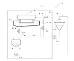
- FIG. 1 It is a schematic diagram of a paint circulation way including a paint supply line of DF coater concerning an embodiment of the invention. It is a schematic diagram showing a state where only paint is supplied to the head for DF coater of FIG. 1 at an initial stage. It is a schematic diagram showing the state where paint was supplied to the head for DF coater of FIG. 1 after supplying flushing water at an initial stage. It is a schematic diagram showing a state where these mixed liquids are supplied to the head for DF coater of FIG. 1 while supplying flushing water and paint at an initial stage. It is a schematic diagram showing the open / close state of the valve when supplying only flushing water to the head for DF coater. FIG.
- FIG. 6 is a schematic view showing the open / close state of the valve when the mixed solution of flushing water and paint is supplied to the DF coater head after the state of FIG. 5;
- FIG. 7 is a schematic view showing the open / close state of the valve when the paint is supplied to the DF coater head after the state of FIG. 6;
- FIG. 1 is a schematic view of a paint circulation passage 2 including a paint supply line 1 of a DF coater.
- the DF coater 10 has a DF coater head 11 located at the upper left, a color pan 12 covering the lower side of the DF coater head 11, and a return tank 13 located downstream of these. And a deaerator 14 located downstream of the return tank 13.
- a first circulation pump 15 for feeding the paint Q in the return tank 13 in the paint circulation path 2 is provided on the downstream side of the return tank 13.
- a second circulation pump 16 for feeding the paint Q after degassing by the degassing machine 14 in the paint circulation path 2 is provided on the downstream side of the degassing machine 14.
- the paint Q which has flowed down from the DF coater head 11 into a curtain film is collected by the color pan 12 and sent from the discharge port 12 a of the color pan 12 to the return tank 13.
- the paint Q stored in the return tank 13 is sent to the defoamer 14 by the first circulation pump 15.
- the paint Q removed by the degassing machine 14 is again sent to the DF coater head 11 by the second circulation pump 16. That is, the circulation path 2 of the coating material Q is comprised by these structures.
- the DF coater 10 in the present embodiment is provided with a paint supply line 1 which constitutes a part of the circulation passage 2.
- a flushing water on-off valve 21a is disposed between the DF coater head 11 and the degassing machine 14 in the circulation path 2 described above and disposed downstream of the DF coater head 11.
- a check valve 21b is provided.
- the paint supply line 1 is provided with a release switching valve 22 disposed downstream of the DF coater head 11 and between the color pan 12 and the return tank 13.
- the paint supply line 1 is provided with a color bypass switching valve 23 disposed downstream of the check valve 21 b and between the check valve 21 b and the defoamer 14.
- the paint supply line 1 is provided with a color bypass 30 connecting the color bypass switching valve 23 and the return tank 13.
- the release switching valve 22 and the color bypass switching valve 23 are each a three-way valve.
- the flushing water on-off valve 21a, the check valve 21b, the release switching valve 22, and the color bypass switching valve 23 are designed to be opened and closed in response to a signal from a control device (not shown). . In addition, you may make it open and close manually, without using a control apparatus. The details of the opening and closing operation will be described later.
- the flushing water on-off valve 21 a is an on-off valve for supplying the flushing water W, and switching of whether to supply the flushing water W to the paint circulation path 2 can be performed by opening and closing the valve. Further, the check valve 21 b prevents the paint Q and the flushing water W from flowing back from the DF coater head 11 side to the defoaming machine 14 side.
- the release switching valve 22 sends the paint Q flowing down from the color pan 12 to the return tank 13 by opening / closing the valve, or the flushing water W or the paint Q containing the flushing water W from the flushing water outlet to the circulation passage 2 It is intended to make it possible to switch between release and release.
- the color bypass 30 allows the paint Q to be sent directly from the defoamer 14 to the return tank 13 without passing through the DF coater head 11. Further, the color bypass switching valve 23 is capable of switching whether the paint Q sent from the degassing machine 14 is sent to the DF coater head 11 or to the return tank 13.
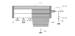
- FIG. 2 is a view showing a case where only the paint is supplied without supplying the flushing water W.
- the paint Q is supplied directly to the DF coater head 11 without supplying the flushing water W at the initial stage of flowing down the paint Q from the head for the DF coater 11, the extruded air A and the paint Q mix together, the paint Air bubbles are generated in Q.
- the air bubbles intrude into the curtain film and cause streak defects with streaks on the coated surface of the coated substrate surface.
- air bubbles adhere to the lip tip of the nozzle 40. As a result, it also enters into the paint Q supplied later, and similarly causes streak defects. This is a conventional problem.
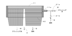
- FIG. 3 is a view showing a case where the paint Q is supplied after the flushing water W is supplied.
- the initial stage only the flushing water W is supplied in advance while the supply of the paint Q is stopped.
- a curtain film of flushing water W is formed from the tip of the nozzle 40 located at the lower end of the DF coater head 11.
- the air present in the chamber chamber (not shown) in the DF coater head 11 or in the gap between the nozzles 40 is pushed out by the flushing water W, and there is no air or bubbles.
- FIG. 4 is a measure against air entering as shown in FIG. 3.
- the supply of the flushing water W is gradually squeezed, and a mixed liquid in which the flushing water W and the paint Q are mixed. It is a figure which shows the case where sandwiching.
- a curtain film of these mixed liquids is formed between the curtain film of the flushing water W and the curtain film of the paint Q. That is, the layer of air A shown in FIG. 3 described above is filled with the mixed solution so that the air A does not enter. As a result, air bubbles do not adhere to the nozzle 40, and the occurrence of streak defects can be effectively prevented.
- the operation of the three valves (the on-off valve 21a, the release switching valve 22, and the color bypass switching valve 23) of the paint supply line 1 will be described with reference to FIGS.
- the open triangles indicate the open state of the valves
- the black triangles indicate the closed states of the valves.
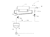
- FIG. 5 is a schematic view showing the open / close state of the valve when only the flushing water W is supplied to the DF coater head 11.
- the flushing on / off valve 21a is opened, and the valve on the DF coater head 11 side of the color bypass switching valve 23 is closed to stop the supply of the paint Q.
- the valve on the color bypass 30 side of the color bypass switching valve 23 is opened.
- the paint Q in the circulation passage 2 is led to the color bypass 30 side by the color bypass switching valve 23, enters the return tank 13, and circulates in the circulation passage 2 through this passage.
- the flushing water W is prevented from flowing backward to the color bypass switching valve 23 by the check valve 21 b.
- the valve on the return tank 13 side of the release switching valve 22 is closed. Open the valve. As a result, the flushing water W is discharged from the discharge path without entering the circulation path 2.
- FIG. 6 is a schematic view showing the open / close state of the valve when the mixed liquid of the flushing water W and the paint Q is supplied to the DF coater head 11 after the state of FIG. From the state of FIG. 5, the on-off valve 23 is controlled to close the valve on the color bypass 30 side and open the valve on the DF coater head 11 side. As a result, the paint Q in the circulation passage 2 is led to the DF coater head 11 side without flowing to the color bypass 30 side. As a result, the mixed liquid of the paint Q and the flushing water W is supplied to the DF coater head 11.
- the release switching valve 22 is in the same state, and the mixed solution flowing down from the DF coater head 11 is discharged from the discharge path.
- the flow rate of the flushing water on-off valve 21a is gradually narrowed to adjust the flow rate of the flushing water W, and the supply amount of flushing water W is reduced.
- the concentration of the mixed liquid gradually shifts from a state in which the amount of the flushing water W has been largely diluted to a state in which the concentration of the paint Q becomes high gradually.
- FIG. 7 is a schematic view showing the open / close state of the valve when the paint is supplied to the DF coater head after the state of FIG. From the state of FIG. 6, the flushing water on-off valve 21a is closed so that only the paint Q is supplied to the DF coater head 11. As a result, a curtain film in which only the paint Q flows down is formed from the nozzle 40 of the DF coater head 11.
- the release switching valve 22 closes the valve on the discharge path side and opens the valve on the return tank 13 side. As a result, the paint Q flows into the return tank 13 through the release switching valve 22, circulates in the circulation path 2, and is supplied again to the DF coater head 11.
- the flushing water on-off valve 21a for supplying the flushing water W to the nozzle 40 instead of the paint Q on the upstream side of the DF coater head 11 Therefore, the flushing water W can be supplied to the head for DF coater 11 to form a curtain film with the flushing water W, and thereafter, a curtain film can be formed with the paint Q. Therefore, air bubbles can be prevented from adhering to the lip tip of the nozzle 40 in the initial stage of forming the curtain film with the flushing water W.
- the curtain film is formed with the paint Q, the flushing water W is rapidly switched to the paint, so the air existing in the nozzle 40 does not enter the paint Q as air bubbles. Also, the curtain film will be replaced without interruption. As a result, it is possible to prevent streak defects from occurring in the coating film formed on the substrate.
- the coating water Q that has flowed down from the DF coater head 11 is provided with the circulation path 2 that supplies again to the DF coater head 11 and the flushing water W that has flowed down from the DF coater head 11 downstream of the DF coater head 11 And a color bypass 30 for connecting the upstream side of the flushing water on-off valve 21a and the downstream side of the discharge switching valve 22. Since the color bypass switching valve 23 that switches the flow of the paint Q to the color bypass 30 is provided, the paint supply line 1 can be configured in the circulation path 2 in which the paint Q circulates.
- the curtain film can be formed with the flushing water W at the initial stage of forming the curtain film, and thereafter the curtain film can be formed with the paint Q.
- air bubbles can be prevented from adhering to the tip of the lip of the nozzle 40, and a streak defect can be prevented from being generated in the coating film.
- the DF coater 10 is disposed on the upstream side of the DF coater head 11 and supplies flushing water W to the nozzle 40
- the flushing water on-off valve 21a is opened to supply the flushing water W to the head for DF coater 11
- the paint Q and the air A are mixed to prevent generation of air bubbles in the paint. Therefore, air bubbles do not adhere to the tip of the lip of the nozzle 40, and a streak defect can be prevented from being generated in the coating film.
- the paint Q is supplied to the head for DF coater 11 to form a curtain film with the mixed liquid of the flushing water W and the paint Q Therefore, if there is a difference between the viscosity of the flushing water W and the paint Q, the curtain film of the flushing water W and the curtain film of the paint Q can be supplied by supplying a mixed solution of the flushing water W and the paint Q.
- the air A can be prevented from entering during the period. As a result, air bubbles do not adhere to the tip of the lip of the nozzle 40, and a streak defect can be prevented from being generated in the coating film.
- the DF coater 10 is disposed on the downstream side of the DF coater head 11 in the circulation path 2 where the paint Q which has flowed down from the DF coater head 11 is supplied again to the DF coater head 11.
- the release switching valve 22 is opened to flush flushing water W out of the circulation passage 2
- the circulation path 2 in which the paint Q circulates It is possible to configure the charge supply line 1.
- the curtain film can be formed with the flushing water W at the initial stage of forming the curtain film, and thereafter the curtain film can be formed with the paint Q.
- air bubbles can be prevented from adhering to the tip of the lip of the nozzle 40, and a streak defect can be prevented from being generated in the coating film.
- the present invention is not limited to the embodiment described above, and the technical idea of the present invention Various modifications and changes are possible based on the
- the paint Q is circulated in the circulation path 2 in the present embodiment, the paint Q may not be circulated.
- the flushing water W is supplied at the initial stage of forming the curtain film by providing only the flushing water on-off valve 21a in the path and making the paint Q and the flushing water W switch quickly. Is formed, and then the paint Q is supplied to form a curtain film, so that the paint Q and the air A are not mixed and air bubbles are not generated in the paint Q.
Landscapes
- Coating Apparatus (AREA)
- Application Of Or Painting With Fluid Materials (AREA)
Abstract
基材の塗膜にストリーク欠陥を発生させることがないDFコータの塗料供給ラインおよびDFコータの塗料供給方法を提供する。 塗料Qをカーテン膜状に流下させるノズル40を備えたDFコータ用ヘッド11に塗料を供給するためのDFコータの塗料供給ラインであって、DFコータ用ヘッド11の上流側に、塗料Qの替わりにフラッシング水Wをノズル40に供給するためのフラッシング水開閉弁21aを設けた。また、ノズル40から塗料Qをカーテン膜状に流下させる初期段階で、フラッシング水開閉弁21aを開いてフラッシング水WをDFコータ用ヘッド11に供給する。
Description
本発明は、塗料をカーテン膜状に流下させて基材に塗工するためのDFコータの塗料供給ライン及びDFコータの塗料供給方法に関する。
従来、紙などのテープ状の基材に塗膜を形成するためのDF(Direct Fountain)コータが知られている。このDFコータは、DFコータ用ヘッドに供給される脱泡された塗料を滞留させることなくスムースに下部のノズル部に導き、このノズル部で塗料の流れを幅方向均一に整流してノズル先端から流出させて均一な安定した流量のカーテン膜を形成する。そして、このカーテン膜を基材に当てた瞬間に基材と同速に引き伸ばすことによって、基材に均一に塗工するものである(例えば、特許文献1参照)。
上述したDFコータ用ヘッドでは、カーテン膜を形成する初期段階において、ノズル内に入り込む塗料とノズル内に存在していた空気とが混ざり合い、ノズルのリップ先端に気泡が付着してしまうことがある。この気泡は、カーテン膜を形成する塗料内に入り込み、塗装後の塗膜にストリーク欠陥を引き起こすことがある。
本発明は、上述した事情を鑑みてなされたものであり、基材の塗膜にストリーク欠陥を発生させることがないDFコータの塗料供給ラインおよびDFコータの塗料供給方法を提供するためのものである。
上述課題を解決するため、本発明は、塗料をカーテン膜状に流下させるノズルを備えたDFコータ用ヘッドに塗料を供給するためのDFコータの塗料供給ラインであって、前記DFコータ用ヘッドの上流側に、前記塗料の替わりにフラッシング水を前記ノズルに供給するためのフラッシング水開閉弁を設けたことを特徴とする。
また、前記DFコータ用ヘッドから流下した前記塗料が前記DFコータ用ヘッドに再び供給される循環路を備え、前記DFコータ用ヘッドの下流側に、前記DFコータ用ヘッドから流下した前記フラッシング水を前記循環路外へ放出するための放出用切換弁を設けることもできる。
さらに、前記フラッシング水開閉弁の上流側と、前記放出用切換弁の下流側とを接続するカラーバイパスを設け、前記循環路に前記塗料の流れを前記カラーバイパスへと切り替えるカラーバイパス切換弁を設けることもできる。
他方、本発明は、塗料をカーテン膜状に流下させるノズルを備えたDFコータ用ヘッドに塗料を供給するためのDFコータの塗料供給方法であって、前記DFコータには、前記DFコータ用ヘッドの上流側に配置され、フラッシング水を前記ノズルに供給するためのフラッシング水開閉弁が設けられ、前記ノズルから塗料をカーテン膜状に流下させる初期段階で、前記フラッシング水開閉弁を開いて前記フラッシング水を前記DFコータ用ヘッドに供給し、前記フラッシング水で前記カーテン膜を形成することを特徴とする。
また、前記フラッシング水を前記DFコータ用ヘッドに供給して前記カーテン膜を形成した後に、前記DFコータ用ヘッドに塗料を供給して、前記フラッシング水と前記塗料の混合液でカーテン膜を形成するようにしてもよい。
さらに、前記DFコータは、前記DFコータ用ヘッドから流下した前記塗料が前記DFコータ用ヘッドに再び供給される循環路内に、前記DFコータ用ヘッドの下流側に配置され、前記DFコータ用ヘッドから流下した前記フラッシング水を前記循環路外へ放出するための放出用切換弁と、前記フラッシング水開閉弁の上流側と前記放出用切換弁の下流側とを接続するカラーバイパスへと前記塗料の流れを切り替えるカラーバイパス切換弁とを備え、前記フラッシング水開閉弁を開いて前記フラッシング水を供給するときに、前記放出用切換弁を開いて前記フラッシング水を前記循環路外へと放出するとともに、前記カラーバイパス切換弁を開いて前記塗料をカラーバイパスへと流すようにしてもよい。
本発明に係るDFコータの塗料供給ラインによれば、塗料をカーテン膜状に流下させるノズルを備えたDFコータ用ヘッドに塗料を供給するためのDFコータの塗料供給ラインであって、前記DFコータ用ヘッドの上流側に、前記塗料の替わりにフラッシング水を前記ノズルに供給するためのフラッシング水開閉弁を設けているので、DFコータ用ヘッドにフラッシング水を供給して、フラッシング水でカーテン膜を形成し、その後に塗料でカーテン膜を形成することができる。そのため、フラッシング水でカーテン膜を形成する最初の段階でノズルのリップ先端に気泡を付着させないようにすることができる。また、塗料でカーテン膜を形成する際には、フラッシング水から塗料に迅速に切り替わるので、ノズル内部に存在していた空気が塗料内に気泡として入り込むことがない。また、カーテン膜が途切れることなく置き換わることになる。その結果、基材に形成した塗膜にストリーク欠陥を発生させないようにすることができる。
また、塗料をカーテン膜状に流下させるノズルを備えたDFコータ用ヘッドに塗料を供給するためのDFコータの塗料供給方法であって、前記DFコータには、前記DFコータ用ヘッドの上流側に配置され、フラッシング水を前記ノズルに供給するためのフラッシング水開閉弁が設けられ、前記ノズルから塗料をカーテン膜状に流下させる初期段階で、前記フラッシング水開閉弁を開いて前記フラッシング水を前記DFコータ用ヘッドに供給することによって、カーテン膜を形成する初期段階で塗料と空気が混じり合って塗料中に気泡が発生することがない。そのため、ノズルのリップ先端に気泡が付着することがなくなり、塗膜にストリーク欠陥を発生させないようにすることができる。
以下、本発明の実施の形態に係るDFコータの塗料供給ライン1について、図面を用いて詳細に説明する。
図1は、DFコータの塗料供給ライン1を含む塗料循環路2の概要図である。
図1は、DFコータの塗料供給ライン1を含む塗料循環路2の概要図である。
DFコータ10は、図1に示すように、左上に位置するDFコータ用ヘッド11と、このDFコータ用ヘッド11の下側を覆うカラーパン12と、これらの下流側に位置するリターンタンク13と、このリターンタンク13の下流側に位置する脱泡機14とを備えている。
また、リターンタンク13の下流側には、リターンタンク13内の塗料Qを塗料循環路2内で送流させるための第1循環ポンプ15が設けられている。また、脱泡機14の下流側には、脱泡機14で脱泡した後の塗料Qを塗料循環路2内で送流させるための第2循環ポンプ16が設けられている。
DFコータ用ヘッド11からカーテン膜状に流下した塗料Qは、カラーパン12で集められ、カラーパン12の排出口12aからリターンタンク13へ送られる。リターンタンク13で貯留された塗料Qは、第1循環ポンプ15によって脱泡機14へと送られる。そして、脱泡機14で脱法された塗料Qは、第2循環ポンプ16によって再びDFコータ用ヘッド11へと送られる。すなわち、これらの構成により、塗料Qの循環路2が構成されている。
また、本実施の形態におけるDFコータ10には、図1に示すように、循環路2内の一部を構成する塗料供給ライン1が設けられている。この塗料供給ライン1には、上述した循環路2において、DFコータ用ヘッド11と脱泡機14との間に位置し、DFコータ用ヘッド11の下流側に配置されたフラッシング水開閉弁21aと逆止弁21bとが設けられている。
また、塗料供給ライン1には、DFコータ用ヘッド11の下流側であって、カラーパン12とリターンタンク13との間に配置された放出用切換弁22が設けられている。
さらに、塗料供給ライン1には、逆止弁21bの下流側であって、逆止弁21bと脱泡機14との間に配置されたカラーバイパス切換弁23が設けられている。また、塗料供給ライン1には、カラーバイパス切換弁23とリターンタンク13とを接続するカラーバイパス30が設けられている。
また、塗料供給ライン1には、DFコータ用ヘッド11の下流側であって、カラーパン12とリターンタンク13との間に配置された放出用切換弁22が設けられている。
さらに、塗料供給ライン1には、逆止弁21bの下流側であって、逆止弁21bと脱泡機14との間に配置されたカラーバイパス切換弁23が設けられている。また、塗料供給ライン1には、カラーバイパス切換弁23とリターンタンク13とを接続するカラーバイパス30が設けられている。
放出用切換弁22およびカラーバイパス切換弁23は、それぞれ三方弁である。そして、これらのフラッシング水開閉弁21a、逆止弁21b、放出用切換弁22、カラーバイパス切換弁23は、図示しない制御装置からの信号を受けて、弁の開閉が行われるようになっている。なお、制御装置を用いずに、手動で開閉するようにしてもよい。この開閉動作についての詳細は後述する。
フラッシング水開閉弁21aは、フラッシング水Wを供給するための開閉弁であり、この弁の開閉によって、塗料循環路2にフラッシング水Wを供給するかの切換が可能になっている。
また、逆止弁21bは、DFコータ用ヘッド11側から脱泡機14側へと塗料Qおよびフラッシング水Wが逆流するのを防止している。
また、逆止弁21bは、DFコータ用ヘッド11側から脱泡機14側へと塗料Qおよびフラッシング水Wが逆流するのを防止している。
放出用切換弁22は、この弁の開閉によって、カラーパン12から流下してきた塗料Qをリターンタンク13へ送るか、フラッシング水Wまたはフラッシング水Wを含む塗料Qをフラッシング水放出口から循環路2の外へ放出するかの切換を可能にするためのものである。
カラーバイパス30は、塗料Qが脱泡機14からDFコータ用ヘッド11を経由せず、直接リターンタンク13へ送流させることができるようになっている。
また、カラーバイパス切換弁23は、この脱泡機14から送られる塗料QをDFコータ用ヘッド11に送るかリターンタンク13に送るかの切換が可能になっている。
また、カラーバイパス切換弁23は、この脱泡機14から送られる塗料QをDFコータ用ヘッド11に送るかリターンタンク13に送るかの切換が可能になっている。
次に、本発明のDFコータの塗料供給ラインの作用について図2~図4を用いて説明する。
図2は、フラッシング水Wを供給せずに塗料のみを供給した場合を示す図である。
DFコータ用ヘッド11から塗料Qを流下させる初期段階で、DFコータ用ヘッド11にフラッシング水Wを供給せずに直接に塗料Qを供給した場合、押し出す空気Aと塗料Qとが混ざり合い、塗料Qの中に気泡が発生する。この気泡は、カーテン膜の中に入り込み、塗工された基材表面の塗面に筋状の痕がつくストリーク欠陥を引き起こす。また、気泡はノズル40のリップ先端部に付着する。その結果、後から供給される塗料Qの中にも入り込み、同様にストリーク欠陥を引き起こすことになる。これが従来の課題であった。
DFコータ用ヘッド11から塗料Qを流下させる初期段階で、DFコータ用ヘッド11にフラッシング水Wを供給せずに直接に塗料Qを供給した場合、押し出す空気Aと塗料Qとが混ざり合い、塗料Qの中に気泡が発生する。この気泡は、カーテン膜の中に入り込み、塗工された基材表面の塗面に筋状の痕がつくストリーク欠陥を引き起こす。また、気泡はノズル40のリップ先端部に付着する。その結果、後から供給される塗料Qの中にも入り込み、同様にストリーク欠陥を引き起こすことになる。これが従来の課題であった。
図3は、フラッシング水Wを供給した後に、塗料Qを供給した場合を示す図である。
初期段階では、塗料Qの供給を停止させた状態で、あらかじめフラッシング水Wのみが供給されるようにする。これにより、DFコータ用ヘッド11の下端に位置するノズル40の先端部からは、フラッシング水Wによるカーテン膜が形成される。この状態では、DFコータ用ヘッド11内の図示しないチャンバ室やノズル40の隙間に存在する空気は、フラッシング水Wによって押し出され、空気や気泡がない状態になる。
初期段階では、塗料Qの供給を停止させた状態で、あらかじめフラッシング水Wのみが供給されるようにする。これにより、DFコータ用ヘッド11の下端に位置するノズル40の先端部からは、フラッシング水Wによるカーテン膜が形成される。この状態では、DFコータ用ヘッド11内の図示しないチャンバ室やノズル40の隙間に存在する空気は、フラッシング水Wによって押し出され、空気や気泡がない状態になる。
一方、フラッシング水と塗料Qとの粘度に差がない場合には問題ないが、粘度に差がある場合には、図3のように、フラッシング水Wと塗料Qとの間に隙間が生じてしまう。より詳細には、フラッシング水Wの供給を停止し、その後に塗料Qのみを供給した場合(フラッシング水Wと塗料Qとの供給を完全に切り替えた場合)、粘度の小さいフラッシング水Wのみが先に流下してしまい、粘度の高い塗料Qがノズル40に残留してしまう。そのため、フラッシング水Wと塗料Qとの間に隙間ができ、この隙間に空気Aが入り込んでしまう。その結果、気泡がノズル40に付着してしまい、カーテン膜の中に気泡が入り込み、上述した場合と同様に、ストリーク欠陥を引き起こしてしまうことになる。
図4は、図3のように空気が入り込んでしまう場合の対策であって、塗料Qを供給する際にフラッシング水Wの供給を徐々に絞り、フラッシング水Wと塗料Qとが混合した混合液を間に挟んだ場合を示す図である。
まず、初期段階でフラッシング水Wのみを供給してノズル40からフラッシング水Wによるカーテン膜を形成する。そして、塗料Qの供給をしながら、フラッシング水Wの供給を少しずつ絞ることによって、フラッシング水Wと塗料Qとの混合液を形成する。その後、フラッシング水Wの供給を完全に停止し、塗料Qのみを供給する。
この方法によれば、図4に示すように、フラッシング水Wのカーテン膜と塗料Qのカーテン膜との間に、これらの混合液のカーテン膜が形成される。すなわち、上述した図3で示した空気Aの層を、混合液で満たすことで空気Aが侵入しないようにする。これにより、ノズル40に気泡が付着することがなく、ストリーク欠陥の発生を効果的に防止することができる。
まず、初期段階でフラッシング水Wのみを供給してノズル40からフラッシング水Wによるカーテン膜を形成する。そして、塗料Qの供給をしながら、フラッシング水Wの供給を少しずつ絞ることによって、フラッシング水Wと塗料Qとの混合液を形成する。その後、フラッシング水Wの供給を完全に停止し、塗料Qのみを供給する。
この方法によれば、図4に示すように、フラッシング水Wのカーテン膜と塗料Qのカーテン膜との間に、これらの混合液のカーテン膜が形成される。すなわち、上述した図3で示した空気Aの層を、混合液で満たすことで空気Aが侵入しないようにする。これにより、ノズル40に気泡が付着することがなく、ストリーク欠陥の発生を効果的に防止することができる。
次に、塗料供給ライン1の3つの弁(開閉弁21a、放出用切換弁22、カラーバイパス切換弁23)の動作について、図5~図7を用いて説明する。なお、図5~図7で示す各弁21a、22、23において、白抜きの三角形は弁の開状態を示し、黒塗りの三角形は弁の閉状態を示している。
図5は、DFコータ用ヘッド11にフラッシング水Wのみを供給しているときの弁の開閉状態を示す概要図である。
DFコータ用ヘッド11でカーテン膜を形成させる初期段階では、図5に示すように、DFコータ用ヘッド11に塗料Qを供給せず、フラッシング水Wのみを供給する。そのために、フラッシング開閉弁21aを開状態にするとともに、カラーバイパス切換弁23のDFコータ用ヘッド11側の弁を閉じて塗料Qの供給を停止させておく。また、塗料Qを循環路2内で循環させるために、カラーバイパス切換弁23のカラーバイパス30側の弁を開く。これにより、循環路2内の塗料Qは、カラーバイパス切換弁23によってカラーバイパス30側に導かれてリターンタンク13内へと入り込み、この経路で循環路2内を循環するようになる。なお、フラッシング水Wは、逆止弁21bによってカラーバイパス切換弁23側へ逆流しないようにする。
DFコータ用ヘッド11でカーテン膜を形成させる初期段階では、図5に示すように、DFコータ用ヘッド11に塗料Qを供給せず、フラッシング水Wのみを供給する。そのために、フラッシング開閉弁21aを開状態にするとともに、カラーバイパス切換弁23のDFコータ用ヘッド11側の弁を閉じて塗料Qの供給を停止させておく。また、塗料Qを循環路2内で循環させるために、カラーバイパス切換弁23のカラーバイパス30側の弁を開く。これにより、循環路2内の塗料Qは、カラーバイパス切換弁23によってカラーバイパス30側に導かれてリターンタンク13内へと入り込み、この経路で循環路2内を循環するようになる。なお、フラッシング水Wは、逆止弁21bによってカラーバイパス切換弁23側へ逆流しないようにする。
一方、DFコータ用ヘッド11から流下したフラッシング水Wの循環路2内への侵入を阻止すべく、放出用切換弁22のリターンタンク13側の弁を閉じ、循環路2からの排出経路側の弁を開く。これにより、フラッシング水Wは、循環路2内に入り込むことなく、排出経路から排出されることになる。
図6は、図5の状態の後に、DFコータ用ヘッド11にフラッシング水Wと塗料Qの混合液を供給しているときの弁の開閉状態を示す概要図である。
図5の状態から、開閉弁23を制御し、カラーバイパス30側の弁を閉じ、DFコータ用ヘッド11側の弁を開く。これにより、循環路2内の塗料Qは、カラーバイパス30側へ流れることなくDFコータ用ヘッド11側へと導かれることになる。これにより、塗料Qとフラッシング水Wとの混合液がDFコータ用ヘッド11へと供給されることになる。
図5の状態から、開閉弁23を制御し、カラーバイパス30側の弁を閉じ、DFコータ用ヘッド11側の弁を開く。これにより、循環路2内の塗料Qは、カラーバイパス30側へ流れることなくDFコータ用ヘッド11側へと導かれることになる。これにより、塗料Qとフラッシング水Wとの混合液がDFコータ用ヘッド11へと供給されることになる。
一方、放出用切換弁22はそのままの状態であり、DFコータ用ヘッド11から流下した混合液は、排出経路から排出されることになる。
また、上述した開閉弁23の制御と同時に、フラッシング水開閉弁21aの流量を調整するように徐々に絞り込み、フラッシング水Wの供給量を少なくしていく。これにより、混合液の濃度は、最初はフラッシング水Wの量が多く希釈された状態から、徐々に塗料Qの濃度が濃い状態へと推移する。
また、上述した開閉弁23の制御と同時に、フラッシング水開閉弁21aの流量を調整するように徐々に絞り込み、フラッシング水Wの供給量を少なくしていく。これにより、混合液の濃度は、最初はフラッシング水Wの量が多く希釈された状態から、徐々に塗料Qの濃度が濃い状態へと推移する。
図7は、図6の状態の後に、DFコータ用ヘッドに塗料を供給しているときの弁の開閉状態を示す概要図である。
図6の状態から、フラッシング水開閉弁21aを閉じ、DFコータ用ヘッド11に塗料Qのみが供給されるようにする。これにより、DFコータ用ヘッド11のノズル40からは、塗料Qのみが流下するカーテン膜が形成される。
一方、放出用切換弁22は、排出経路側の弁を閉じ、リターンタンク13側の弁を開く。これにより、塗料Qは、放出用切換弁22を介してリターンタンク13側へ流れ込み、循環路2内を循環し、再びDFコータ用ヘッド11へと供給されるようになる。
図6の状態から、フラッシング水開閉弁21aを閉じ、DFコータ用ヘッド11に塗料Qのみが供給されるようにする。これにより、DFコータ用ヘッド11のノズル40からは、塗料Qのみが流下するカーテン膜が形成される。
一方、放出用切換弁22は、排出経路側の弁を閉じ、リターンタンク13側の弁を開く。これにより、塗料Qは、放出用切換弁22を介してリターンタンク13側へ流れ込み、循環路2内を循環し、再びDFコータ用ヘッド11へと供給されるようになる。
上述した図5~図7のように開閉弁21a、放出用切換弁22、カラーバイパス切換弁23を制御することにより、図4に示すように、フラッシング水Wおよび塗料Qのカーテン膜の間に、混合液のカーテン膜を形成することができる。
本発明の実施の形態に係るDFコータの塗料供給ライン1によれば、DFコータ用ヘッド11の上流側に、塗料Qの替わりにフラッシング水Wをノズル40に供給するためのフラッシング水開閉弁21aを設けているので、DFコータ用ヘッド11にフラッシング水Wを供給して、フラッシング水Wでカーテン膜を形成し、その後に塗料Qでカーテン膜を形成することができる。そのため、フラッシング水Wでカーテン膜を形成する最初の段階でノズル40のリップ先端に気泡を付着させないようにすることができる。また、塗料Qでカーテン膜を形成する際には、フラッシング水Wから塗料に迅速に切り替わるので、ノズル40内部に存在していた空気が塗料Q内に気泡として入り込むことがない。また、カーテン膜が途切れることなく置き換わることになる。その結果、基材に形成した塗膜にストリーク欠陥を発生させないようにすることができる。
また、DFコータ用ヘッド11から流下した塗料QがDFコータ用ヘッド11に再び供給される循環路2を備え、DFコータ用ヘッド11の下流側に、DFコータ用ヘッド11から流下したフラッシング水Wを循環路2外へ放出するための放出用切換弁22を設け、フラッシング水開閉弁21aの上流側と、放出用切換弁22の下流側とを接続するカラーバイパス30を設け、循環路2に塗料Qの流れをカラーバイパス30へと切り替えるカラーバイパス切換弁23を設けているので、塗料Qが循環する循環路2内に、塗料供給ライン1を構成することができる。これにより、循環路2を構成する構造であっても、カーテン膜を形成する初期段階でフラッシング水Wでカーテン膜を形成し、その後に塗料Qでカーテン膜を形成するようにすることができる。その結果、ノズル40のリップ先端に気泡が付着することを防止でき、塗膜にストリーク欠陥を発生させないようにすることができる。
他方、本発明の実施の形態に係るDFコータの塗料供給方法によれば、DFコータ10には、DFコータ用ヘッド11の上流側に配置され、フラッシング水Wをノズル40に供給するためのフラッシング水開閉弁21aが設けられ、ノズル40から塗料Qをカーテン膜状に流下させる初期段階で、フラッシング水開閉弁21aを開いてフラッシング水WをDFコータ用ヘッド11に供給することによって、カーテン膜を形成する初期段階で塗料Qと空気Aが混じり合って塗料中に気泡が発生することがない。そのため、ノズル40のリップ先端に気泡が付着することがなくなり、塗膜にストリーク欠陥を発生させないようにすることができる。
また、フラッシング水WをDFコータ用ヘッド11に供給してカーテン膜を形成した後に、DFコータ用ヘッド11に塗料Qを供給して、フラッシング水Wと塗料Qの混合液でカーテン膜を形成しているので、フラッシング水Wと塗料Qとの粘度に差がある場合には、フラッシング水Wと塗料Qとの混合液を供給することで、フラッシング水Wのカーテン膜と塗料Qのカーテン膜との間に空気Aが入り込まないようにすることができる。これにより、ノズル40のリップ先端に気泡が付着することがなくなり、塗膜にストリーク欠陥を発生させないようにすることができる。
さらに、DFコータ10は、DFコータ用ヘッド11から流下した塗料QがDFコータ用ヘッド11に再び供給される循環路2内に、DFコータ用ヘッド11の下流側に配置され、DFコータ用ヘッド11から流下したフラッシング水Wを循環路2外へ放出するための放出用切換弁22と、フラッシング水開閉弁21aの上流側と放出用切換弁22の下流側とを接続するカラーバイパス30へと塗料Qの流れを切り替えるカラーバイパス切換弁23とを備え、フラッシング水開閉弁21aを開いてフラッシング水Wを供給するときに、放出用切換弁22を開いてフラッシング水Wを循環路2外へと放出するとともに、カラーバイパス切換弁23を開いて塗料Qをカラーバイパス30へと流すことによって、塗料Qが循環する循環路2内に、塗料供給ライン1を構成することができる。これにより、循環路2を構成する構造であっても、カーテン膜を形成する初期段階でフラッシング水Wでカーテン膜を形成し、その後に塗料Qでカーテン膜を形成するようにすることができる。その結果、ノズル40のリップ先端に気泡が付着することを防止でき、塗膜にストリーク欠陥を発生させないようにすることができる。
以上、本発明の実施の形態に係るDFコータの塗料供給ライン1及びDFコータの渡洋供給方法について述べたが、本発明は既述の実施形態に限定されるものではなく、本発明の技術思想に基づいて各種の変形および変更が可能である。
例えば、本実施の形態では、塗料Qを循環路2内で循環させる構造にしているが、塗料Qを循環させない構造であってもよい。この場合、経路内にフラッシング水開閉弁21aのみを設け、塗料Qとフラッシング水Wとを迅速に切り替えられる構造にすることで、カーテン膜を形成する初期段階でフラッシング水Wを供給してカーテン膜を形成し、その後に塗料Qを供給してカーテン膜を形成することで、塗料Qと空気Aが混ざり合って塗料Q内に気泡が発生することがなくなる。これにより、ノズルのリップ先端に気泡が付着しなくなり、塗膜にストリーク欠陥が発生するのを防止することができる。
例えば、本実施の形態では、塗料Qを循環路2内で循環させる構造にしているが、塗料Qを循環させない構造であってもよい。この場合、経路内にフラッシング水開閉弁21aのみを設け、塗料Qとフラッシング水Wとを迅速に切り替えられる構造にすることで、カーテン膜を形成する初期段階でフラッシング水Wを供給してカーテン膜を形成し、その後に塗料Qを供給してカーテン膜を形成することで、塗料Qと空気Aが混ざり合って塗料Q内に気泡が発生することがなくなる。これにより、ノズルのリップ先端に気泡が付着しなくなり、塗膜にストリーク欠陥が発生するのを防止することができる。
1 DFコータの塗料供給ライン
2 塗料循環路
10 DFコータ
11 DFコータ用ヘッド
11a 供給口
12 カラーパン
12a 排出口
13 リターンタンク
14 脱泡機
15 第1ポンプ
16 第2ポンプ
21a フラッシング水開閉弁
21b 逆止弁
22 放出用切換弁
23 カラーバイパス切換弁
30 カラーバイパス
40 ノズル
Q 塗料
W フラッシング水
A 空気
2 塗料循環路
10 DFコータ
11 DFコータ用ヘッド
11a 供給口
12 カラーパン
12a 排出口
13 リターンタンク
14 脱泡機
15 第1ポンプ
16 第2ポンプ
21a フラッシング水開閉弁
21b 逆止弁
22 放出用切換弁
23 カラーバイパス切換弁
30 カラーバイパス
40 ノズル
Q 塗料
W フラッシング水
A 空気
Claims (6)
- 塗料をカーテン膜状に流下させるノズルを備えたDFコータ用ヘッドに塗料を供給するためのDFコータの塗料供給ラインであって、
前記DFコータ用ヘッドの上流側に、前記塗料の替わりにフラッシング水を前記ノズルに供給するためのフラッシング水開閉弁を設けたことを特徴とするDFコータの塗料供給ライン。 - 前記DFコータ用ヘッドから流下した前記塗料が前記DFコータ用ヘッドに再び供給される循環路を備え、前記DFコータ用ヘッドの下流側に、前記DFコータ用ヘッドから流下した前記フラッシング水を前記循環路外へ放出するための放出用切換弁を設けたことを特徴とする請求項1に記載のDFコータの塗料供給ライン。
- 前記フラッシング水開閉弁の上流側と、前記放出用切換弁の下流側とを接続するカラーバイパスを設け、前記循環路に前記塗料の流れを前記カラーバイパスへと切り替えるカラーバイパス切換弁を設けたことを特徴とする請求項2に記載のDFコータの塗料供給ライン。
- 塗料をカーテン膜状に流下させるノズルを備えたDFコータ用ヘッドに塗料を供給するためのDFコータの塗料供給方法であって、
前記DFコータには、前記DFコータ用ヘッドの上流側に配置され、フラッシング水を前記ノズルに供給するためのフラッシング水開閉弁が設けられ、
前記ノズルから塗料をカーテン膜状に流下させる初期段階で、前記フラッシング水開閉弁を開いて前記フラッシング水を前記DFコータ用ヘッドに供給し、前記フラッシング水で前記カーテン膜を形成することを特徴とするDFコータの塗料供給方法。 - 前記フラッシング水を前記DFコータ用ヘッドに供給して前記カーテン膜を形成した後に、前記DFコータ用ヘッドに塗料を供給して、前記フラッシング水と前記塗料の混合液でカーテン膜を形成することを特徴とする請求項4に記載のDFコータの塗料供給方法。
- 前記DFコータは、前記DFコータ用ヘッドから流下した前記塗料が前記DFコータ用ヘッドに再び供給される循環路内に、前記DFコータ用ヘッドの下流側に配置され、前記DFコータ用ヘッドから流下した前記フラッシング水を前記循環路外へ放出するための放出用切換弁と、前記フラッシング水開閉弁の上流側と前記放出用切換弁の下流側とを接続するカラーバイパスへと前記塗料の流れを切り替えるカラーバイパス切換弁とを備え、
前記フラッシング水開閉弁を開いて前記フラッシング水を供給するときに、前記放出用切換弁を開いて前記フラッシング水を前記循環路外へと放出するとともに、前記カラーバイパス切換弁を開いて前記塗料をカラーバイパスへと流すことを特徴とする請求項4または請求項5に記載のDFコータの塗料供給方法。
Priority Applications (2)
| Application Number | Priority Date | Filing Date | Title |
|---|---|---|---|
| JP2012528533A JPWO2012020477A1 (ja) | 2010-08-10 | 2010-08-10 | Dfコータの塗料供給ライン及びdfコータの塗料供給方法 |
| PCT/JP2010/063578 WO2012020477A1 (ja) | 2010-08-10 | 2010-08-10 | Dfコータの塗料供給ライン及びdfコータの塗料供給方法 |
Applications Claiming Priority (1)
| Application Number | Priority Date | Filing Date | Title |
|---|---|---|---|
| PCT/JP2010/063578 WO2012020477A1 (ja) | 2010-08-10 | 2010-08-10 | Dfコータの塗料供給ライン及びdfコータの塗料供給方法 |
Publications (1)
| Publication Number | Publication Date |
|---|---|
| WO2012020477A1 true WO2012020477A1 (ja) | 2012-02-16 |
Family
ID=45567457
Family Applications (1)
| Application Number | Title | Priority Date | Filing Date |
|---|---|---|---|
| PCT/JP2010/063578 Ceased WO2012020477A1 (ja) | 2010-08-10 | 2010-08-10 | Dfコータの塗料供給ライン及びdfコータの塗料供給方法 |
Country Status (2)
| Country | Link |
|---|---|
| JP (1) | JPWO2012020477A1 (ja) |
| WO (1) | WO2012020477A1 (ja) |
Citations (3)
| Publication number | Priority date | Publication date | Assignee | Title |
|---|---|---|---|---|
| JPH11101184A (ja) * | 1997-09-29 | 1999-04-13 | Konica Corp | ギヤポンプの流量制御方法 |
| JPH11276973A (ja) * | 1998-03-30 | 1999-10-12 | Konica Corp | 塗布液の送液方法 |
| JP2001087698A (ja) * | 1999-09-22 | 2001-04-03 | Ishikawajima Harima Heavy Ind Co Ltd | カーテンコータ用カラー脱泡装置 |
-
2010
- 2010-08-10 JP JP2012528533A patent/JPWO2012020477A1/ja active Pending
- 2010-08-10 WO PCT/JP2010/063578 patent/WO2012020477A1/ja not_active Ceased
Patent Citations (3)
| Publication number | Priority date | Publication date | Assignee | Title |
|---|---|---|---|---|
| JPH11101184A (ja) * | 1997-09-29 | 1999-04-13 | Konica Corp | ギヤポンプの流量制御方法 |
| JPH11276973A (ja) * | 1998-03-30 | 1999-10-12 | Konica Corp | 塗布液の送液方法 |
| JP2001087698A (ja) * | 1999-09-22 | 2001-04-03 | Ishikawajima Harima Heavy Ind Co Ltd | カーテンコータ用カラー脱泡装置 |
Also Published As
| Publication number | Publication date |
|---|---|
| JPWO2012020477A1 (ja) | 2013-10-28 |
Similar Documents
| Publication | Publication Date | Title |
|---|---|---|
| US9440458B2 (en) | Liquid application apparatus and image forming system | |
| TW200900162A (en) | Slit nozzle | |
| JP5023828B2 (ja) | 塗料供給経路の洗浄方法 | |
| TWI664025B (zh) | Applicator, coating device and coating method | |
| ITRM960225A1 (it) | Dispositivo di inchiostrazione da usare in una macchina da stampa. | |
| JP2010531223A (ja) | 塗布方法及び流し掛け式塗布装置 | |
| ITMI20111034A1 (it) | Dispositivo per la stampa a getto d'inchiostro di una superficie | |
| JP4835003B2 (ja) | スリットノズル及びスリットノズルの気泡排出方法並びに塗布装置 | |
| CN104264398A (zh) | 一种印染用自动喷淋水装置 | |
| JP2001137764A (ja) | 塗布装置及び塗布方法 | |
| JPWO2012020477A1 (ja) | Dfコータの塗料供給ライン及びdfコータの塗料供給方法 | |
| CN202860775U (zh) | 一种用于液晶显示器的涂胶装置 | |
| JP4524767B2 (ja) | 液体吐出装置 | |
| JP5949038B2 (ja) | 塗布装置 | |
| CN117696377A (zh) | 一种具有清理功能的涂胶装置 | |
| CN211492847U (zh) | 喷头装置及三维成型设备 | |
| JP2007142133A (ja) | レジスト希釈システム | |
| CN1129411A (zh) | 无需再循环,流体由模子供给且可加入溶剂的刮片调节型辊式涂覆机 | |
| JP2021030473A (ja) | 粘度コントローラ | |
| JP2017047381A (ja) | 塗工装置 | |
| JPH11319685A (ja) | 液体供給装置 | |
| KR20150108732A (ko) | 도포 시공 장치 및 도포 시공막의 제조 방법 | |
| US20020114893A1 (en) | Method for preparing a coating hopper | |
| JP6203620B2 (ja) | 塗工装置 | |
| JP5634231B2 (ja) | シャワー式塗装装置 |
Legal Events
| Date | Code | Title | Description |
|---|---|---|---|
| 121 | Ep: the epo has been informed by wipo that ep was designated in this application |
Ref document number: 10855878 Country of ref document: EP Kind code of ref document: A1 |
|
| WWE | Wipo information: entry into national phase |
Ref document number: 2012528533 Country of ref document: JP |
|
| NENP | Non-entry into the national phase |
Ref country code: DE |
|
| 122 | Ep: pct application non-entry in european phase |
Ref document number: 10855878 Country of ref document: EP Kind code of ref document: A1 |