WO2012018051A1 - クリーニング方法、デバイス製造方法、クリーニング基板、液浸部材、液浸露光装置、及びダミー基板 - Google Patents
クリーニング方法、デバイス製造方法、クリーニング基板、液浸部材、液浸露光装置、及びダミー基板 Download PDFInfo
- Publication number
- WO2012018051A1 WO2012018051A1 PCT/JP2011/067787 JP2011067787W WO2012018051A1 WO 2012018051 A1 WO2012018051 A1 WO 2012018051A1 JP 2011067787 W JP2011067787 W JP 2011067787W WO 2012018051 A1 WO2012018051 A1 WO 2012018051A1
- Authority
- WO
- WIPO (PCT)
- Prior art keywords
- liquid
- cleaning
- substrate
- immersion member
- exposure
- Prior art date
- Legal status (The legal status is an assumption and is not a legal conclusion. Google has not performed a legal analysis and makes no representation as to the accuracy of the status listed.)
- Ceased
Links
Images






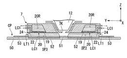
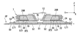


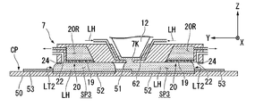
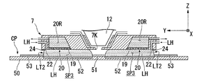



Classifications
-
- G—PHYSICS
- G03—PHOTOGRAPHY; CINEMATOGRAPHY; ANALOGOUS TECHNIQUES USING WAVES OTHER THAN OPTICAL WAVES; ELECTROGRAPHY; HOLOGRAPHY
- G03F—PHOTOMECHANICAL PRODUCTION OF TEXTURED OR PATTERNED SURFACES, e.g. FOR PRINTING, FOR PROCESSING OF SEMICONDUCTOR DEVICES; MATERIALS THEREFOR; ORIGINALS THEREFOR; APPARATUS SPECIALLY ADAPTED THEREFOR
- G03F7/00—Photomechanical, e.g. photolithographic, production of textured or patterned surfaces, e.g. printing surfaces; Materials therefor, e.g. comprising photoresists; Apparatus specially adapted therefor
- G03F7/70—Microphotolithographic exposure; Apparatus therefor
- G03F7/70216—Mask projection systems
- G03F7/70341—Details of immersion lithography aspects, e.g. exposure media or control of immersion liquid supply
-
- G—PHYSICS
- G03—PHOTOGRAPHY; CINEMATOGRAPHY; ANALOGOUS TECHNIQUES USING WAVES OTHER THAN OPTICAL WAVES; ELECTROGRAPHY; HOLOGRAPHY
- G03F—PHOTOMECHANICAL PRODUCTION OF TEXTURED OR PATTERNED SURFACES, e.g. FOR PRINTING, FOR PROCESSING OF SEMICONDUCTOR DEVICES; MATERIALS THEREFOR; ORIGINALS THEREFOR; APPARATUS SPECIALLY ADAPTED THEREFOR
- G03F7/00—Photomechanical, e.g. photolithographic, production of textured or patterned surfaces, e.g. printing surfaces; Materials therefor, e.g. comprising photoresists; Apparatus specially adapted therefor
- G03F7/70—Microphotolithographic exposure; Apparatus therefor
- G03F7/708—Construction of apparatus, e.g. environment aspects, hygiene aspects or materials
- G03F7/70908—Hygiene, e.g. preventing apparatus pollution, mitigating effect of pollution or removing pollutants from apparatus
- G03F7/70925—Cleaning, i.e. actively freeing apparatus from pollutants, e.g. using plasma cleaning
Definitions
- the present invention relates to a cleaning method, a device manufacturing method, a cleaning substrate, an immersion member, an immersion exposure apparatus, and a dummy substrate.
- This application claims priority based on Japanese Patent Application No. 2010-175810 for which it applied on August 4, 2010, and uses the content here.
- an exposure apparatus that exposes a substrate with exposure light is used.
- a member or component of the exposure apparatus is contaminated, for example, an exposure failure such as a defect formed in a pattern formed on the substrate may occur, and as a result, a defective device may occur. Therefore, for example, a technique for cleaning a predetermined member in the exposure apparatus has been devised as disclosed in the following patent document.
- An object of an aspect of the present invention is to provide a cleaning method and a cleaning substrate capable of suppressing the occurrence of exposure failure. Another object of the present invention is to provide an immersion member and an immersion exposure apparatus that can suppress the occurrence of exposure failure. Another object of the present invention is to provide a device manufacturing method that can suppress the occurrence of defective devices. Another object of the present invention is to provide a dummy substrate that can suppress the occurrence of exposure failure.
- the substrate in the immersion exposure apparatus, includes an opening through which the exposure light applied to the substrate passes and at least a part of the optical path of the exposure light is filled with the first liquid.
- a liquid immersion member cleaning method for holding a first liquid between the first portion and the first portion that is liquid repellent with respect to the second liquid for cleaning, and a first portion disposed around at least a part of the periphery of the first portion.
- the cleaning method of the first aspect cleaning the liquid immersion member, holding the first liquid between the cleaned liquid immersion member and the substrate, There is provided a device manufacturing method including exposing a substrate with exposure light through a first liquid and developing the exposed substrate.
- the exposure light having an opening through which the exposure light applied to the substrate passes and a liquid recovery port disposed at least at a part of the periphery of the opening are provided.
- a cleaning substrate used for cleaning the liquid immersion member that holds the first liquid with the substrate so that at least a part of the liquid is filled with the first liquid, and is liquid repellent with respect to the second liquid for cleaning And a second part that is more lyophilic than the first part with respect to the second liquid, and the liquid immersion member is made of the second liquid.
- a cleaning substrate that prevents the first liquid from passing through the opening of the second liquid supplied between the liquid immersion member and the second portion when disposed to face the liquid immersion member for cleaning. Is provided.
- the substrate is used in an immersion exposure apparatus that exposes the substrate with exposure light through the first liquid, and at least a part of the optical path of the exposure light is filled with the first liquid.
- a liquid immersion member that holds the first liquid between the opening, an opening through which the exposure light passes, a liquid recovery port disposed at least at a part of the periphery of the opening, and an outside of the liquid recovery port with respect to the opening And a supply port for supplying a second liquid for cleaning.
- an immersion exposure apparatus for exposing a substrate with exposure light through a first liquid, the immersion exposure apparatus comprising the liquid immersion member of the fourth aspect. .
- a device manufacturing method including exposing a substrate using the immersion exposure apparatus of the fifth aspect and developing the exposed substrate.
- a dummy substrate used in a non-exposure operation different from an exposure operation for exposing a substrate of an immersion exposure apparatus that exposes the substrate with exposure light via a liquid
- a dummy substrate is provided having a notch associated with a non-exposure operation in a portion.
- the occurrence of exposure failure can be suppressed. Moreover, according to the aspect of the present invention, the occurrence of defective devices can be suppressed.
- an XYZ orthogonal coordinate system is set, and the positional relationship of each part will be described with reference to this XYZ orthogonal coordinate system.
- a predetermined direction in the horizontal plane is defined as an X-axis direction
- a direction orthogonal to the X-axis direction in the horizontal plane is defined as a Y-axis direction
- a direction orthogonal to each of the X-axis direction and the Y-axis direction (that is, a vertical direction) is defined as a Z-axis direction.
- the rotation (inclination) directions around the X axis, Y axis, and Z axis are the ⁇ X, ⁇ Y, and ⁇ Z directions, respectively.
- FIG. 1 is a schematic block diagram that shows an example of an exposure apparatus EX according to the present embodiment.
- the exposure apparatus EX of the present embodiment is an immersion exposure apparatus that exposes a substrate P with exposure light EL through an exposure liquid LQ.
- the immersion space LS is formed so that at least a part of the optical path of the exposure light EL is filled with the exposure liquid LQ.
- the immersion space is a portion (space, region) filled with liquid.
- the substrate P is exposed with the exposure light EL through the exposure liquid LQ in the immersion space LS.
- water pure water
- the exposure apparatus EX of the present embodiment is an exposure apparatus provided with a substrate stage and a measurement stage as disclosed in, for example, US Pat. No. 6,897,963 and European Patent Application Publication No. 1713113.
- an exposure apparatus EX measures a mask stage 1 that can move while holding a mask M, a substrate stage 2 that can move while holding a substrate P, and exposure light EL without holding the substrate P.
- a measuring stage 3 mounted with a measuring member C (measuring instrument) to be moved, an illumination system IL for illuminating the mask M with the exposure light EL, and an image of the pattern of the mask M illuminated with the exposure light EL are displayed on the substrate P.
- a projection optical system PL that projects onto the projection surface, a liquid immersion member 7 that can form an immersion space LS so that the optical path K of the exposure light EL emitted from the projection optical system PL is filled with the exposure liquid LQ, and the entire exposure apparatus EX And a control device 8 for controlling the operation.
- the mask M includes a reticle on which a device pattern projected onto the substrate P is formed.
- the mask M includes a transmission type mask having a transparent plate such as a glass plate and a pattern formed on the transparent plate using a light shielding material such as chromium.
- a reflective mask can also be used as the mask M.
- the substrate P is a substrate for manufacturing a device.
- a device pattern can be formed on the substrate P.
- the substrate P includes, for example, a base material such as a semiconductor wafer and a photosensitive film formed on the base material.
- the photosensitive film is a film of a photosensitive material (photoresist).
- the substrate P may include another film in addition to the photosensitive film.
- the substrate P may include an antireflection film or a protective film (topcoat film) that protects the photosensitive film.
- the illumination system IL irradiates the predetermined illumination area IR with the exposure light EL.
- the illumination area IR includes a position where the exposure light EL emitted from the illumination system IL can be irradiated.
- the exposure light EL emitted from the illumination system IL for example, bright lines (g line, h line, i line) emitted from a mercury lamp, and far ultraviolet light (DUV light) such as KrF excimer laser light (wavelength 248 nm), ArF excimer laser light (wavelength 193 nm), vacuum ultraviolet light (VUV light) such as F 2 laser light (wavelength 157 nm), or the like is used.
- ArF excimer laser light is used as the exposure light EL emitted from the illumination system IL.
- the mask stage 1 is movable on the guide surface 9G of the base member 9.
- the mask stage 1 has a mask holding unit 1H that holds the mask M in a releasable manner.
- the mask stage 1 is movable to a position where the exposure light EL emitted from the illumination system IL can be irradiated with the mask M held by the mask holding unit 1H.
- Projection optical system PL irradiates exposure light EL to a predetermined projection region PR.
- the projection optical system PL has an exit surface 13 that emits the exposure light EL toward the image plane of the projection optical system PL.
- the terminal optical element 12 closest to the image plane of the projection optical system PL has the exit surface 13.
- the projection region PR includes a position where the exposure light EL emitted from the emission surface 13 can be irradiated.
- the projection optical system PL projects an image of the pattern of the mask M at a predetermined projection magnification onto at least a part of the substrate P arranged in the projection region PR.
- the projection optical system PL of the present embodiment is a reduction system whose projection magnification is, for example, 1/4, 1/5, or 1/8. Note that the projection optical system PL may be either an equal magnification system or an enlargement system.
- the optical axis AX of the projection optical system PL is parallel to the Z axis.
- the exposure light EL emitted from the emission surface 13 travels in the ⁇ Z direction.
- the projection optical system PL may form either an inverted image or an erect image.
- the substrate stage 2 and the measurement stage 3 are movable on the guide surface 10G of the base member 10.
- the substrate stage 2 includes a substrate holding unit 11 that holds the substrate P in a releasable manner.
- the substrate stage 2 can be moved to a position where the exposure light EL emitted from the projection optical system PL can be irradiated with the substrate P held by the substrate holder 11.
- the measurement stage 3 has a holding portion 3H that holds the measurement member C so as to be releasable.
- the measurement stage 3 is movable to a position where the exposure light EL emitted from the projection optical system PL can be irradiated with the measurement member C held by the holding unit 3H.
- the substrate stage 2 is disposed on at least a part of the periphery of the substrate holding portion 11 as disclosed in, for example, US Patent Application Publication No. 2007/0177125, US Patent Application Publication No. 2008/0049209, and the like.
- a holding portion TH that holds the member T so as to be releasable is provided.
- the cover member T is disposed around the substrate P held by the substrate holding unit 11.
- the upper surface of the substrate holding unit 11 facing the + Z direction may be exposed around the substrate P held by the substrate holding unit 11.
- the immersion space LS may be formed in at least a part of the upper surface of the substrate holding unit 11.
- the measurement member C mounted on the measurement stage 3 may be a member constituting a part of an aerial image measurement system as disclosed in, for example, US Patent Application Publication No. 2002/0041377, or US Pat. No. 4,465,368. Or a reference member disclosed in US Pat. No. 5,493,403, etc., or US Patent Application Publication No. 2002/0061469. May be a member constituting a part of an irradiation amount measuring system as disclosed in Japanese Patent No. 1, etc., or a member constituting a part of a wavefront aberration measuring system as disclosed in European Patent No. 1079223 .
- the mask stage 1 can be moved by the operation of the drive system 4.
- the drive system 4 includes a planar motor having a mover 4 ⁇ / b> A disposed on the mask stage 1 and a stator 4 ⁇ / b> C disposed on the base member 9.
- the mask stage 1 can move in six directions on the guide surface 9G in the X axis, Y axis, Z axis, ⁇ X, ⁇ Y, and ⁇ Z directions by the operation of the drive system 4.
- the drive system 5 includes a planar motor having a mover 5A disposed on the substrate stage 2, a mover 5B disposed on the measurement stage 3, and a stator 5C disposed on the base member 10.
- Each of the substrate stage 2 and the measurement stage 3 can move in six directions on the guide surface 10G in the X axis, Y axis, Z axis, ⁇ X, ⁇ Y, and ⁇ Z directions by the operation of the drive system 5.
- An example of a flat motor is disclosed in, for example, US Pat. No. 6,452,292.
- the drive system 4 may include, for example, a linear motor.
- the drive system 5 may include a linear motor, for example.
- the positions of the mask stage 1, the substrate stage 2, and the measurement stage 3 are measured by the interferometer system 6.
- the control device 8 When executing the exposure processing of the substrate P or when executing the predetermined measurement processing, the control device 8 operates the drive systems 4 and 5 based on the measurement result of the interferometer system 6 to thereby perform the mask stage 1 (mask M ), Position control of the substrate stage 2 (substrate P) and the measurement stage 3 (measurement member C) is executed.
- each of the upper surface 2F of the substrate stage 2 and the upper surface 3F of the measurement stage 3 is liquid repellent with respect to the exposure liquid LQ.
- the upper surface 2F of the present embodiment includes the upper surface of the cover member T.
- the upper surfaces 2F and 3F are surfaces facing the + Z direction, and can face the terminal optical element 12 and the liquid immersion member 7.
- the upper surfaces 2F and 3F of the present embodiment are formed of a film of a material containing fluorine.
- the immersion member 7 can form an immersion space LS so that the optical path K of the exposure light EL emitted from the emission surface 13 is filled with the exposure liquid LQ.
- the liquid immersion member 7 is disposed in the vicinity of the last optical element 12.
- the liquid immersion member 7 of this embodiment is an annular member. At least a part of the liquid immersion member 7 of this embodiment is disposed around the last optical element 12. Further, at least a part of the liquid immersion member 7 of the present embodiment is disposed around the optical path K of the exposure light EL emitted from the emission surface 13.
- the liquid immersion member 7 may be disposed at least at a part of the periphery of the last optical element 12 and may not be disposed around the optical path K of the exposure light EL emitted from the exit surface 13.
- the liquid immersion member 7 may be disposed at least part of the periphery of the optical path K of the exposure light EL emitted from the exit surface 13 and may not be disposed around the terminal optical element 12.
- a plurality of liquid immersion members may be arranged around the optical path of the exposure light EL with an interval.
- the liquid immersion member 7 has a lower surface 14 that can be opposed to an object disposed at a position (projection region PR) where the exposure light EL emitted from the last optical element 12 can be irradiated.
- the liquid immersion member 7 holds the exposure light EL between the object and the liquid immersion space LS so that at least a part of the optical path K of the exposure light EL emitted from the emission surface 13 is filled with the exposure liquid LQ.
- the optical path K of the exposure light EL between the last optical element 12 and the object Is filled with the exposure liquid LQ.
- the objects that can be arranged in the projection region PR include objects that can move on the image plane side of the projection optical system PL (the exit surface 13 side of the terminal optical element 12).
- the object is a substrate stage 2, a substrate P held on the substrate stage 2, a cleaning substrate CP described later, a dummy substrate described later, a measurement stage 3, and a measurement member C mounted on the measurement stage 3. Including at least one.
- the liquid immersion member 7 holds the exposure liquid LQ with the substrate P so that at least a part of the optical path K of the exposure light EL irradiated to the substrate P is filled with the exposure liquid LQ. .
- the emission surface 13 and the lower surface 14 is in contact with the exposure liquid LQ.
- the immersion space LS is formed so that a part of the surface of the substrate P including the projection region PR is covered with the exposure liquid LQ when the substrate P is irradiated with the exposure light EL. .
- the liquid immersion member 7 holds the exposure liquid LQ in a local area smaller than the substrate P. At least a part of the interface (meniscus, edge) LGq of the exposure liquid LQ is formed between the lower surface 14 of the liquid immersion member 7 and the surface of the substrate P. That is, the exposure apparatus EX of the present embodiment employs a local liquid immersion method.
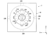
- FIG. 2A is a view of the liquid immersion member 7 of the present embodiment as viewed from the upper side (+ Z side), and FIG. 2B is a view as viewed from the lower side ( ⁇ Z side).
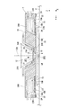
- FIG. 3 is a cross-sectional view parallel to the YZ plane showing the liquid immersion member 7 of the present embodiment.
- FIG. 3 shows a case where the substrate P is disposed at a position facing the terminal optical element 12 and the liquid immersion member 7, but as described above, for example, the substrate stage 2, the measurement stage 3, etc. Other objects may be placed.
- the liquid immersion member 7 has a plate portion 15 and a main body portion 16.
- the outer shape of the liquid immersion member 7 (main body portion 16) is a rectangle.
- the external shape of the main-body part 16 is not restricted to a rectangle.
- the outer shape of the main body 16 may be any one of a circle, an ellipse, a polygon, a shape obtained by rounding some corners of a polygon, a shape whose outline is a free curve, and a combination of these shapes. Good.
- the outer shape of the liquid immersion member 7 (main body portion 16) may be the same circle as the outer shape of the second supply port 22 described later.
- the plate portion 15 is disposed around the optical path K of the exposure light EL emitted from the emission surface 13. At least a part of the main body portion 16 is disposed around the terminal optical element 12.
- the plate portion 15 has a lower surface 15B that can be opposed to the surface of the substrate P, and an upper surface 15A that faces the opposite direction of the lower surface 15B. At least a part of the upper surface 15A faces the emission surface 13.
- the outer shape of the lower surface 15B of the plate portion 15 is a rectangle. Note that the outer shape of the lower surface 15B is not limited to a rectangle.
- the outer shape of the lower surface 15B may be any of a circle, an ellipse, a polygon, a shape obtained by rounding some corners of the polygon, a shape whose outline is a free curve, and a shape obtained by combining these shapes.
- the liquid immersion member 7 has an opening (passage) 7K through which the exposure light EL emitted from the emission surface 13 can pass.
- the exposure light EL emitted from the emission surface 13 and applied to the substrate P passes through the opening 7K.
- the opening 7 ⁇ / b> K is formed in the plate portion 15.
- the opening 7K is formed so as to connect the upper surface 15A and the lower surface 15B.
- the lower surface 15B is disposed around the lower end of the opening 7K.
- the upper surface 15A is disposed around the upper end of the opening 7K.
- the exposure light EL emitted from the emission surface 13 can pass through the opening 7K and irradiate the substrate P.
- the traveling direction of the exposure light EL emitted from the exit surface 13 is parallel to the optical axis 12A of the last optical element 12.
- the optical axis 12A of the present embodiment is parallel to the Z axis.
- the size of the opening 7K in the Y-axis direction is smaller than the size of the opening 7K in the X-axis direction.
- the opening 7K of the present embodiment is rectangular.
- the shape of the opening 7K may be any one of an ellipse, a circle, a polygon, a shape obtained by rounding some corners of a polygon, a shape whose outline is a free curve, and a combination of these shapes. .
- the liquid immersion member 7 includes a first supply port 21 that can supply the exposure liquid LQ and a liquid recovery port 20 that can recover the exposure liquid LQ. At least during exposure of the substrate P, the first supply port 21 supplies the exposure liquid LQ, and the liquid recovery port 20 recovers at least a part of the exposure liquid LQ supplied from the first supply port 21. In the exposure of the substrate P, the substrate P is disposed so as to face the liquid immersion member 7. The exposure liquid LQ is supplied from the first supply port 21 in a state where the substrate P is disposed so as to face the liquid immersion member 7.
- the liquid immersion member 7 of the present embodiment has a second supply port 22 different from the first supply port 21.
- the second supply port 22 can supply a liquid different from the exposure liquid LQ.
- the second supply port 22 of the present embodiment can supply the cleaning liquid LC used for cleaning at least a part of the liquid immersion member 7.
- the cleaning liquid LC used for cleaning may be one type or two or more types. In the following description, one type or two types of cleaning solutions are collectively referred to as a cleaning solution LC.
- the first cleaning liquid LC1 and the second cleaning liquid LC2 are used as the cleaning liquid LC.
- the liquid immersion member 7 includes a first internal channel 21R connected to the first supply port 21, a second internal channel 22R connected to the second supply port 22, and a third internal channel connected to the liquid recovery port 20. 20R.
- Each of the first internal flow path 21R, the second internal flow path 22R, and the third internal flow path 20R is formed inside the liquid immersion member 7.
- the first supply port 21 is formed at one end of the first internal channel 21R.
- the second supply port 22 is formed at one end of the second internal flow path 22R.
- the liquid recovery port 20 is formed at one end of the third internal channel 20R.
- the first supply port 21 of the present embodiment is arranged so as to face the optical path K in the vicinity of the optical path K of the exposure light EL.
- a plurality of first supply ports 21 are arranged.
- the first supply ports 21 of the present embodiment are arranged on the + X side, ⁇ X side, + Y side, and ⁇ Y side with respect to the optical path K, respectively.
- the first supply port 21 of the present embodiment supplies the exposure liquid LQ to the space SP1 between the emission surface 13 and the upper surface 15A. After the exposure liquid LQ supplied from the first supply port 21 flows through the space SP1, it passes through the opening 7K and enters the space SP2 between the lower surface 15B (lower surface 14) and the surface of the substrate P (the upper surface of the object). Flowing.
- the position of the 1st supply port 21 is not restricted to the above-mentioned position. Further, the number of first supply ports 21 is not limited to four, and may be one.
- the liquid recovery port 20 can recover at least a part of the exposure liquid LQ on the substrate P (object).
- the liquid recovery port 20 is disposed at a predetermined position of the liquid immersion member 7 that can face the surface of the substrate P.
- the liquid recovery port 20 in the present embodiment is disposed at least at a part around the opening 7K.
- the lower surface 15B is disposed around the opening 7K, and the liquid recovery port 20 is disposed at least partly around the lower surface 15B.
- the liquid recovery port 20 of the present embodiment is annular in the XY plane and is disposed around the lower surface 15B.
- a plurality of liquid recovery ports 20 may be arranged at a predetermined interval so as to surround the lower surface 15B.
- the porous member 19 is disposed in the liquid recovery port 20.
- the porous member 19 has a plurality of openings (openings or pores).
- the porous member 19 of the present embodiment is a plate-like member.
- the porous member 19 of the present embodiment has a lower surface 19B that can be opposed to the surface of the substrate P, and an upper surface 19A that faces the opposite direction of the lower surface 19B.
- the hole 19H of the porous member 19 is formed so as to connect the upper surface 19A and the lower surface 19B.
- the porous member 19 has a plurality of holes 19H.
- the lower surface 19B is parallel to the XY plane, but at least a part of the lower surface 19B may be inclined with respect to the XY plane. Further, at least a part of the lower surface 19B may include a curved surface. Further, there may be a step in part of the lower surface 19B.
- the first region of the lower surface 19B disposed around the lower surface 15B (opening 7K) is disposed at the first position in the Z-axis direction
- the second region of the lower surface 19B disposed around the first region is the first.
- the second position may be higher than the first position.
- the second region of the lower surface 19B may be disposed at a position lower than the first region.
- the lower surface 15B and the lower surface 19B are arranged at the same position in the Z-axis direction, but they may be arranged at different positions.
- the lower surface 19B may be disposed at a position higher than the lower surface 15B (position on the + Z side, position far from the substrate P).
- the lower surface 19B may be disposed at a position lower than the lower surface 15B (a position on the ⁇ Z side, a position close to the substrate P).
- the lower surface 19B of the porous member 19 is disposed around the lower surface 15B of the plate portion 15.
- the lower surface 14 of the liquid immersion member 7 that can face the surface of the substrate P (the upper surface of the object) includes the lower surface 15B of the plate portion 15 and the lower surface 19B of the porous member 19.
- the lower surface 14 including the lower surface 15B and the lower surface 19B is disposed around the opening 7K.
- a mesh filter which is a porous member in which a large number of small holes are formed in a mesh shape
- the porous member 19 may not be disposed in the liquid recovery port 20.
- the outer periphery (outer shape) 19BO of the lower surface 19B is circular, but is not limited to circular.
- the shape of the lower surface 19B may be any of a rectangle, an ellipse, a polygon, a shape in which some corners of the polygon are rounded, a shape whose outline is a free curve, or a combination of these shapes.
- the liquid recovery port may include a concept including the hole 19H of the porous member 19.
- porous member 19 may not be disposed in the liquid recovery port 20.
- the exposure liquid LQ (exposure liquid LQ on the object) in the space SP2 is recovered through the hole 19H of the porous member 19.
- the control device 8 causes the pressure of the space SP2 facing the lower surface 19B and the space (third internal flow path 20R) facing the upper surface 19A. Adjust so that the pressure is different (generate differential pressure). Thereby, the exposure liquid LQ on the substrate P is recovered through the holes 19H of the porous member 19.
- the control device 8 performs the recovery operation of the exposure liquid LQ from the liquid recovery port 20 (hole 19H) in parallel with the operation of supplying the exposure liquid LQ from the first supply port 21.
- an immersion space LS is formed with the exposure liquid LQ between the terminal optical element 12 and the liquid immersion member 7 on one side and the substrate P (object) on the other side.
- At least a part of the liquid immersion member 7 of this embodiment is formed of a material containing metal.
- at least a part of the liquid immersion member 7 is formed of a material containing titanium.
- the material containing titanium contains at least one of titanium and a titanium alloy.
- the plate part 15 and the main body part 16 of the present embodiment are formed of a material containing titanium.
- the porous member 19 is also formed of a material containing titanium.
- At least a part of the liquid immersion member 7 may be formed of a material different from titanium, for example, a material containing stainless steel, magnesium, or the like. At least a part of the liquid immersion member 7 may be formed of a material containing ceramics. Further, at least a part of the surface of the liquid immersion member 7 may be formed of amorphous carbon. Amorphous carbon includes tetrahedral amorphous carbon. For example, when at least a part of the upper surface 15A and the lower surface 15B of the plate portion 15 is formed of amorphous carbon, the plate portion 15 (base material) formed of a material containing titanium is formed, and at least one of the surfaces of the base material is formed.
- An amorphous carbon film is formed so that the portion is covered with the amorphous carbon film.
- at least a part of the upper surface 15A and the lower surface 15B is formed of amorphous carbon.
- at least a part of the upper surface 19A, the lower surface 19B, and the inner surface of the hole 19H of the porous member 19 may be formed of amorphous carbon.
- an amorphous carbon film can be formed on a substrate using a CVD method or a PVD method.
- At least a part of the surface of the liquid immersion member 7 may be formed of an oxide film.
- At least a part of the upper surface 19A, the lower surface 19B, and the inner surface of the hole 19H of the porous member 19 may be formed of an oxide film.
- the oxide film may be a titanium oxide film, for example.
- the second supply port 22 is disposed outside the liquid recovery port 20 (hole 19H) with respect to the opening 7K.
- the second supply port 22 is disposed outside the liquid recovery port 20 with respect to the optical axis 12A (optical path K).
- the second supply port 22 of the present embodiment is disposed at the same position (height) as the lower surface 15B of the liquid immersion member 7 in the Z-axis direction.
- the second supply port 22 and the lower surface 15B may be arranged at different positions in the Z-axis direction.
- the second supply port 22 may be arranged at a position higher than the lower surface 15B (position on the + Z side, position far from the substrate P).
- the second supply port 22 may be disposed at a position lower than the lower surface 15B (a position on the ⁇ Z side, a position close to the substrate P).
- the object M is arranged outside the object N with respect to the optical axis 12A. It is said that the object N is disposed inside the object M with respect to the optical axis 12A. That is, with respect to the radiation direction with respect to the optical axis 12A, the object N arranged at a position close to the optical axis 12A is said to be arranged inside the object M arranged at a position far from the optical axis 12A, and is far from the optical axis 12A. The object M arranged at the position is said to be arranged outside the object N arranged at a position close to the optical axis 12A.
- the second supply port 22 of the present embodiment is disposed outside the liquid recovery port 20 with respect to the optical axis 12A of the last optical element 12.
- the second supply port 22 of the present embodiment is annularly provided in the XY plane so as to surround the liquid recovery port 20.
- the second supply port 22 does not have to be in an annular shape surrounding the liquid recovery port 20.
- the number of the second supply ports 22 is one, but a plurality of second supply ports may be provided.
- the plurality of second supply ports may be arranged along the outer peripheral portion of the lower surface 19B.
- the plurality of second supply ports may have the same liquid supply amount for each second supply port or may be different from each other.
- the opening areas of the plurality of second supply ports may be the same or different from each other.
- the outer shape of the liquid recovery port 20 is the same as the outer shape of the lower surface 19B. However, the outer shape of the liquid recovery port 20 may be different from the outer shape of the lower surface 19B.
- the liquid immersion member 7 includes the first supply port 21, the second supply port 22, and the liquid recovery port 20, but at least one of the first supply port 21, the second supply port 22, and the liquid recovery port 20. May be provided in a member different from the liquid immersion member 7. In that case, the member provided with at least one of the first supply port 21, the second supply port 22, and the liquid recovery port 20 and the liquid immersion member 7 may or may not contact each other.
- the first supply port 21 and the liquid recovery port 20 may be provided in the liquid immersion member 7, and the second supply port 22 may be provided in a member different from the liquid immersion member 7.
- the liquid repellent part 24 is disposed outside the second supply port 22 with respect to the optical axis 12A. In the present embodiment, the liquid repellent part 24 is disposed outside the second supply port 22 with respect to the opening 7K.
- the liquid repellent portion 24 is liquid repellent with respect to at least the cleaning liquid LC.
- the liquid repellent part 24 of the present embodiment is disposed so as to surround the second supply port 22 in an annular shape.
- the liquid repellent part 24 of the present embodiment has an annular shape surrounding the optical axis 12A (opening 7K).
- the liquid repellent part 24 of the present embodiment is provided between the outer edge 16 ⁇ / b> A of the main body part 16 and the outer edge 22 ⁇ / b> A of the second supply port 22.
- the liquid repellent portion 24 is provided in all the portions between the outer edge 16 ⁇ / b> A of the main body portion 16 and the outer edge 22 ⁇ / b> A of the second supply port 22.
- the outer edge 24 ⁇ / b> A of the liquid repellent portion 24 of the present embodiment matches the outer edge portion 16 ⁇ / b> A of the main body portion 16.
- the inner edge 24 ⁇ / b> B of the liquid repellent portion 24 of the present embodiment coincides with the outer edge portion 22 ⁇ / b> A of the second supply port 22.
- liquid repellent portion 24 may not be provided. Further, a liquid repellent portion that is at least liquid repellent with respect to the cleaning liquid LC may be provided inside the second supply port 22 with respect to the opening 7K or the optical axis 12A. Also in this case, the liquid repellent part 24 may be provided, or the liquid repellent part 24 may not be provided.
- the liquid repellent portion 24 and the lower surface 15B of the liquid immersion member 7 may be substantially flush with each other. Further, in the Z-axis direction, the liquid repellent portion 24 and the lower surface 15B of the liquid immersion member 7 may be arranged at different positions.
- the second supply port 22 of the present embodiment can supply the cleaning liquid LC (LC1, LC2) to the inside of the liquid repellent part 24.
- the liquid repellent part 24 has liquid repellency with respect to a liquid such as a cleaning liquid supplied from the second supply port 22.
- the contact angle of the cleaning liquid LC with respect to the liquid repellent part 24 is 80 degrees or more, 90 degrees or more, 100 degrees or more, 110 degrees or more, or 120 degrees or more.
- the outer edge 24A of the liquid repellent portion 24 may not coincide with the outer edge portion 16A of the main body portion 16.
- the outer edge 24A of the liquid repellent part 24 may be formed on the inner side of the outer edge 16A of the main body part 16 with respect to the optical axis 12A.
- the outer edge 24A of the liquid repellent portion 24 may be annular.
- the inner edge 24 ⁇ / b> B of the liquid repellent portion 24 of the present embodiment may not coincide with the outer edge portion 22 ⁇ / b> A of the second supply port 22.
- the liquid repellent part 24 disposed outside the second supply port 22 is a liquid repellent film applied to the lower surface 14 of the liquid immersion member 7.
- the liquid repellent part 24 may be formed of a member different from the main body part 16.
- the outer edge 24 ⁇ / b> A of the liquid repellent part 24 and the outer shape of the main body part 16 do not need to match.
- the outer edge 24 ⁇ / b> A of the liquid repellent portion 24 may be larger than the main body portion 16.
- the liquid repellent portion 24 of this embodiment is formed of a material containing fluorine.
- a material containing fluorine is a fluorine-containing resin (fluorine resin), and may be polytetrafluoroethylene (PFA) or polytetrafluoroethylene (PTFE).
- PFA polytetrafluoroethylene
- PTFE polytetrafluoroethylene
- a material different from the material containing fluorine may be used.
- the material different from the material containing fluorine may be, for example, a material containing titanium or a material containing silicon carbonitride. Further, a combination of a material containing fluorine and a material containing other materials may be used.
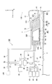
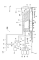
- FIG. 4 is a diagram illustrating an example of the liquid system 100 according to the present embodiment.
- FIG. 4 illustrates a state where the substrate PX selected according to the operation of the exposure apparatus EX is disposed on the substrate stage 2.
- the substrate PX includes a plurality of types of substrates including one or more of a substrate P used during an exposure operation, a cleaning substrate CP used during a non-exposure operation such as cleaning, and a dummy substrate used during a non-exposure operation other than during cleaning such as measurement. Is appropriately selected.
- the liquid system 100 may be a part of a device manufacturing system including the exposure apparatus EX, for example.
- the liquid system 100 may supply liquid to two or more of the plurality of exposure apparatuses EX.
- the liquid system 100 may be an external device (an apparatus different from the exposure apparatus EX) for the exposure apparatus EX. Further, at least a part of the liquid system 100 may be equipment of a factory where the exposure apparatus EX is installed. Further, the exposure apparatus EX may have a part of the liquid system 100 or all of it.
- the liquid system 100 of the present embodiment can supply the exposure liquid LQ to the first internal flow path 21R of the liquid immersion member 7.
- the exposure liquid LQ supplied to the first internal channel 21R is sent to the first supply port 21 via the first internal channel 21R, and is supplied to the space SP1 via the first supply port 21.
- the liquid system 100 of the present embodiment can supply the exposure liquid LQ also to the second internal flow path 22R of the liquid immersion member 7.
- the exposure liquid LQ supplied to the second internal channel 22R is sent to the second supply port 22 via the second internal channel 22R.
- the exposure liquid LQ from the liquid system 100 is a space on the lower side ( ⁇ Z side) of the liquid recovery port 20 via the second supply port 22, and is at least one of the opening 7K and the space SP3 of the second supply port 22. Supplied to the department.
- the liquid system 100 of the present embodiment can supply the cleaning liquid LC to the second internal flow path 22R of the liquid immersion member 7.
- the cleaning liquid LC supplied to the second internal flow path 22R is supplied to at least a part of the space SP3 through the second internal flow path 22R and the second supply port 22, similarly to the exposure liquid LQ.
- the liquid system 100 of the present embodiment can recover the liquid recovered from the liquid recovery port 20 (at least one of the exposure liquid LQ and the cleaning liquid LC).
- the liquid recovered from the liquid recovery port 20 is sent to the liquid system 100 via the third internal channel 20R.
- the exposure liquid LQ recovered from the liquid recovery port 20 in the exposure of the substrate P is sent to the liquid system 100.
- the liquid system 100 may recover the liquid (at least one of the exposure liquid LQ and the cleaning liquid LC) recovered from the second supply port 22.
- the liquid system 100 may be able to collect the exposure liquid LQ from the second supply port 22.
- the liquid system 100 includes a supply source LQS, flow path members 25 to 34, valves 35 to 37, a dilution device 38, a first cleaning liquid supply device 39, a second cleaning liquid supply device 40, a suction device 41, and a detection device 42. And accommodating members 43-45.
- the supply source LQS can supply the exposure liquid LQ.
- the supply source LQS may be a part of the exposure apparatus EX or a part of the liquid system 100, or may be a part of a system different from the liquid system 100 and an external apparatus of the exposure apparatus EX.
- the flow path members 25 to 34 each include a pipe member such as a pipe.
- the valves 35 to 37 can perform at least one of flow rate adjustment and flow path switching.
- the dilution device 38 can mix two or more kinds of liquids at a desired mixing ratio.
- the dilution device 38 can adjust the ratio (concentration) of each component included in the liquid before mixing to the mixed liquid.
- the first cleaning liquid supply device 39 can supply the first cleaning liquid LC1 as one of the cleaning liquid LC.
- the second cleaning liquid supply device 40 can supply the second cleaning liquid LC2 as one of the cleaning liquid LC.
- the second cleaning liquid LC2 of the present embodiment is a cleaning liquid having components different from those of the first cleaning liquid LC1.
- the suction device 41 is a pump or the like, for example, and can change the pressure in a region connected to the suction device 41.
- the detection device 42 can detect the characteristics of the liquid.
- the accommodating members 43 to 45 are, for example, tanks and can accommodate a liquid.
- the first supply system capable of supplying the exposure liquid LQ to the first supply port 21 includes a flow path member 25, a valve 35, a flow path member 26, and a first internal flow path 21R.
- One end of the flow path member 25 is connected to the supply source LQS.
- the other end of the flow path member 25 is connected to the inlet of the valve 35.
- the valve 35 includes two outlets, and the flow rate from each outlet can be adjusted.
- the valve 35 can alternatively select an outflow port for flowing the exposure liquid LQ out of two outflow ports.
- a first outlet of the valve 35 is connected to one end of the flow path member 26.
- the other end of the flow path member 26 is connected to the first internal flow path 21R.
- the second supply system capable of supplying the exposure liquid LQ to the second supply port 22 is the flow path member 25, the valve 35, the flow path member 27, the diluting device 38, the flow path member 29, and the valve 36. , The flow path member 30, and the second internal flow path 22R.
- the third supply system capable of supplying the first cleaning liquid LC1 to the second supply port 22 is the first cleaning liquid supply device 39, the flow channel member 28, the diluting device 38, the flow channel member 29, and the valve 36.
- the fourth supply system capable of supplying the second cleaning liquid LC2 to the second supply port 22 includes the second cleaning liquid supply device 40, the valve 36, the flow path member 30, and the second internal flow path 22R. Including.
- the second outlet is connected to one end of the flow path member 27.
- the other end of the flow path member 27 is connected to the dilution device 38.
- the dilution device 38 includes two inlets and one outlet.
- the first inlet of the dilution device 38 is connected to the other end of the flow path member 27.
- the second inlet of the dilution device 38 is connected to the first cleaning liquid supply device 39 via the flow path member 28.
- the outlet of the dilution device 38 is connected to one end of the flow path member 29.
- the first cleaning liquid supply device 39 can supply the first cleaning liquid LC1 to the dilution device 38 via the flow path member 28.
- the diluting device 38 can select any one of the exposure liquid LQ, the first cleaning liquid LC1, and the mixed liquid of the exposure liquid LQ and the first cleaning liquid LC1 to flow through the flow path member 29.
- the diluting device 38 can adjust the mixing ratio between the exposure liquid LQ and the first cleaning liquid LC1.
- the diluting device 38 can adjust the flow rate of the liquid flowing through the flow path member 29.
- the mixed liquid of the exposure liquid LQ and the first cleaning liquid LC1 may be simply referred to as the first cleaning liquid LC1.
- the other end of the flow path member 29 is connected to the valve 36.
- the valve 36 includes two inlets and one outlet. A first inlet of the valve 36 is connected to the other end of the flow path member 29. A second inlet of the valve 36 is connected to the second cleaning liquid supply device 40. The outlet of the valve 36 is connected to one end of the flow path member 30.
- the second cleaning liquid supply device 40 can supply the second cleaning liquid LC2 to the second inlet of the valve 36.
- the valve 36 includes the exposure liquid LQ or the first cleaning liquid LC1 flowing from the flow path member 29, the second cleaning liquid LC2 flowing from the flow path member 29, a mixed liquid of the exposure liquid LQ and the second cleaning liquid LC2, the first cleaning liquid LC1 and the first cleaning liquid LC1. It is possible to select one of the mixed liquids of the two cleaning liquids LC2 and flow it through the flow path member 30. In the following description, the mixed liquid of the exposure liquid LQ and the second cleaning liquid LC2 may be simply referred to as the second cleaning liquid LC2.
- the other end of the flow path member 30 is connected to the second internal flow path 22R.
- the liquid mixture of the exposure liquid LQ, the first cleaning liquid LC1, the second cleaning liquid LC2, the first cleaning liquid LC1, and the second cleaning liquid LC2 can be selected and supplied from the second supply port 22 to the space SP3.
- the recovery system capable of recovering the liquid from the liquid recovery port 20 includes the third internal flow path 20R, the flow path member 31, the suction device 41, the detection device 42, the valve 37, the flow path members 32 to 34, And containment members 43-45.
- One end of the flow path member 31 is connected to the third internal flow path 20R.
- the other end of the flow path member 31 is connected to the valve 37.
- the suction device 41 and the detection device 42 are connected to the flow path in the flow path member 31.
- the suction device 41 sucks the liquid in the third internal flow path 20R toward the flow path member 31.
- the suction device 41 causes the liquid present in the space SP3 to be removed from the liquid recovery port 20 (porous) by making the pressure in the flow path in the flow path member 31 and the pressure in the third internal flow path 20R different from the pressure in the space SP3. Suction is possible from the hole 19H) of the member 19.
- the liquid recovery port 20 may selectively recover a liquid and a gas existing in the space SP3, or may recover a liquid and a gas.
- the detection device 42 measures the characteristics of the liquid flowing from the third internal flow path 20R to the flow path member 31.
- the properties of the liquid include at least one of physical properties and components.
- the physical property includes at least one of density and conductivity.
- the detection result of the detection device 42 may be output to the control device 8, for example.
- the control device 8 can obtain the characteristics of the liquid based on the detection result of the detection device 42.
- the valve 37 includes one inlet and three outlets.
- the inlet of the valve 37 is connected to the other end of the flow path member 31.
- a first outlet of the valve 37 is connected to the housing member 43 via the flow path member 32.
- a second outlet of the valve 37 is connected to the housing member 44 through the flow path member 33.
- a third outlet of the valve 37 is connected to the housing member 45 via the flow path member 34.
- the valve 37 can adjust the flow rate of the liquid flowing out from the first to third outlets.
- the valve 37 according to the present embodiment allows the liquid to flow out of any of the first to third outlets according to the characteristics of the liquid flowing into the valve 37 from the flow path member 31 based on the detection result of the detection device 42, for example. It is possible to select whether to flow.
- the accommodation members 44 to 46 of the present embodiment are tanks.
- the liquid system 100 of the present embodiment can collect and collect the liquid into the accommodating members 43 to 45 in accordance with the characteristics of the liquid in the third internal flow path 20R.
- the first supply system that can supply the exposure liquid LQ to the first supply port 21 and the second supply system that can supply the exposure liquid LQ to the second supply port 22 share a common flow path.
- the structure which does not have may be sufficient.
- the third supply system capable of supplying the first cleaning liquid LC1 to the second supply port 22 and the fourth supply system capable of supplying the second cleaning liquid LC2 to the second supply port 22 share a common flow path.
- the structure which does not have may be sufficient.
- the first to fourth supply systems may not have a common flow path. Two or more of the first to fourth supply systems may have a common flow path.
- the control device 8 moves the substrate stage 2 to the substrate exchange position in order to load (load) the substrate P before exposure onto the substrate stage 2.
- the substrate replacement position is a position away from the liquid immersion member 7 (projection region PR) and a position where the substrate P replacement process can be performed.
- the substrate P replacement process is a process of carrying out (unloading) the exposed substrate P held on the substrate stage 2 (substrate holding unit 11) from the substrate stage 2 using a predetermined transfer device (not shown). And at least one of processing of loading (loading) the substrate P before exposure into the substrate stage 2 (substrate holding unit 11).
- the control device 8 moves the substrate stage 2 to the substrate replacement position and executes the substrate P replacement process.
- the control device 8 arranges the measurement stage 3 at a position facing the terminal optical element 12 and the liquid immersion member 7, and the terminal optical element 12.
- the exposure liquid LQ is held between the liquid immersion member 7 and the measurement stage 3 to form the liquid immersion space LS.
- measurement processing using the measurement stage 3 may be performed as necessary in at least a part of the period in which the substrate stage 2 is separated from the liquid immersion member 7.
- the control device 8 makes the terminal optical element 12 and the liquid immersion member 7 and the measurement stage 3 face each other, and the exposure light EL between the terminal optical element 12 and the measurement member C is used.
- the immersion space LS is formed so that the optical path K is filled with the exposure liquid LQ.
- the control device 8 irradiates the measurement member C (measurement device) held on the measurement stage 3 with the exposure light EL via the projection optical system PL and the exposure liquid LQ, and executes the measurement process of the exposure light EL. .
- the result of the measurement process may be reflected in the exposure process of the substrate P executed thereafter.
- control device 8 moves the substrate stage 2 to the projection region PR, and the last optical element 12 and the liquid immersion member.
- An immersion space LS is formed between 7 and the substrate stage 2 (substrate P).
- the exposure liquid LQ supplied from the supply source LQS is supplied to the first supply port 21 via the flow path in the flow path member 26 and the first internal flow path 21R.
- the first supply port 21 supplies the exposure liquid LQ to the space SP1 (optical path K).
- the exposure liquid LQ supplied to the space SP1 flows into the space SP2 through the opening 7K.
- the operation of recovering the exposure liquid LQ from the liquid recovery port 20 is executed. Thereby, an immersion space LS is formed with the exposure liquid LQ between the last optical element 12 and the immersion member 7 and the substrate P (substrate stage 2).
- the liquid recovery port 20 recovers the exposure liquid LQ in the space SP2.
- the exposure liquid LQ recovered from the liquid recovery port 20 flows through the third internal flow path 20R and the flow path in the flow path member 31.
- the flow path is adjusted by the valve 37 so that the exposure liquid LQ recovered from the liquid recovery port 20 flows through the flow path in the flow path member 32.
- the exposure liquid LQ discharged from the flow path member 32 flows into the storage member 43.
- the control device 8 After the immersion space LS is formed between the last optical element 12 and the liquid immersion member 7 and the substrate stage 2 (substrate P), the control device 8 starts the exposure processing of the substrate P.
- the terminal optical element 12 and the liquid immersion member 7 and the substrate P are arranged to face each other, and the optical path K of the exposure light EL between the terminal optical element 12 and the substrate P is exposed.
- An immersion space LS is formed so as to be filled with the liquid LQ.
- the illumination system IL illuminates the mask M with the exposure light EL.
- the exposure light EL from the mask M is applied to the substrate P through the projection optical system PL and the exposure liquid LQ supplied from the first supply port 21. Thereby, the substrate P is exposed with the exposure light EL emitted from the last optical element 12.
- the pattern image of the mask M is projected onto the substrate P.
- the exposure apparatus EX of the present embodiment is a scanning exposure apparatus (so-called scanning stepper) that projects an image of the pattern of the mask M onto the substrate P while moving the mask M and the substrate P synchronously in a predetermined scanning direction.
- the scanning direction (synchronous movement direction) of the substrate P is the Y-axis direction
- the scanning direction (synchronous movement direction) of the mask M is also the Y-axis direction.
- the control device 8 moves the substrate P in the Y axis direction with respect to the projection region PR of the projection optical system PL, and in the illumination region IR of the illumination system IL in synchronization with the movement of the substrate P in the Y axis direction.
- the substrate P is irradiated with the exposure light EL through the projection optical system PL and the exposure liquid LQ in the immersion space LS on the substrate P while moving the mask M in the Y-axis direction.
- the control device 8 moves the substrate stage 2 to the substrate replacement position.
- the measurement stage 3 is disposed so as to face the last optical element 12 and the liquid immersion member 7, for example.
- the exposed substrate P is unloaded from the substrate stage 2 moved to the substrate exchange position, and the unexposed substrate P is loaded into the substrate stage 2. Thereafter, the control device 8 repeats the above process to sequentially expose the plurality of substrates P.
- the terminal optical element 12 and the liquid immersion member 7 and the terminal optical element are used in at least a part of the exposure sequence including the replacement process of the substrate P, the measurement process using the measurement stage 3, and the exposure process of the substrate P.
- the exposure liquid LQ is supplied from the first supply port 21 between the element 12 and the object (at least one of the substrate P, the substrate stage 2 and the measurement stage 3) arranged to face the liquid immersion member 7. At least a part of the exposure liquid LQ supplied from the first supply port 21 is recovered from the liquid recovery port 20.
- the exposure liquid LQ recovered from the liquid recovery port 20 in the exposure sequence is recovered in the housing member 43.
- no cleaning liquid is supplied from either the first cleaning liquid supply device 39 or the second cleaning liquid supply device 40 during the exposure sequence. That is, the liquid supply from the second supply port 22 is stopped during the exposure sequence.
- the exposure liquid LQ may be recovered from the second supply port 22 by connecting the second supply port 22 to a vacuum system (such as a vacuum pump) during the exposure sequence.
- a vacuum system such as a vacuum pump
- the exposure liquid LQ in the immersion space LS is the terminal optical element during at least a part of the exposure sequence including the replacement process of the substrate P, the measurement process using the measurement stage 3, and the exposure process of the substrate P. 12, contact with at least a part of the liquid immersion member 7, the substrate stage 2, and the measurement stage 3.
- the liquid immersion space LS is improved. There is a possibility that it cannot be formed. As a result, exposure failure may occur.
- the cleaning process is performed at a predetermined timing on the members in the exposure apparatus EX that are in contact with the exposure liquid LQ in the immersion space LS.
- the cleaning process is performed using the cleaning liquid LC.
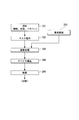
- a cleaning sequence including a cleaning process for the liquid immersion member 7 among the members in the exposure apparatus EX will be described.
- the object is arranged at a position facing the lower surface 14 of the liquid immersion member 7.
- the object may be, for example, the substrate stage 2 (upper surface 2F), the measurement stage 3 (upper surface 3F), or the substrate PX held by the substrate holding unit 11 of the substrate stage 2.
- the substrate PX includes at least one of the substrate P used during the exposure operation, the cleaning substrate CP used during the non-exposure operation such as cleaning, and the dummy substrate used during the non-exposure operation other than during cleaning such as measurement. Including.
- the control device 8 supplies the cleaning liquid LC from the second supply port 22 with the lower surface 14 of the liquid immersion member 7 and the object facing each other. In addition, in parallel with the supply of the cleaning liquid LC from the second supply port 22, the control device 8 performs an operation of recovering at least a part of the cleaning liquid LC supplied from the second supply port 22 from the liquid recovery port 20. .
- the cleaning liquid LC from the second supply port 22 is supplied between the liquid immersion member 7 and the object.
- at least a part of the cleaning liquid LC from the second supply port 22 is held between the liquid immersion member 7 and the object.
- the cleaning liquid LC from the second supply port 22 contacts at least a part of the lower surface 14 of the liquid immersion member 7 including the lower surface 19B of the porous member 19. Thereby, at least a part of the lower surface 14 is cleaned with the cleaning liquid LC.
- the cleaning liquid LC from the second supply port 22 contacts at least a part of the surface of the object disposed at a position facing the liquid immersion member 7. Thereby, at least a part of the surface of the object is also cleaned with the cleaning liquid LC.
- the cleaning liquid LC between the liquid immersion member 7 and the object is recovered from the liquid recovery port 20 (hole 19H).
- the cleaning liquid LC contacts at least part of the inner surface of the hole 19H and the upper surface 19A of the porous member 19. Thereby, the inner surface of the hole 19H and at least a part of the upper surface 19A are cleaned with the cleaning liquid LC.
- the cleaning liquid LC contacts at least a part of the inner surface of the third internal channel 20R. Thereby, at least a part of the inner surface of the third internal channel 20R is cleaned with the cleaning liquid LC.
- the second supply port 22 of the liquid immersion member 7 is disposed outside the liquid recovery port 20 with respect to the opening 7K (optical axis 12A), it is between the cleaning liquid LC lower surface 15B and the object. Inflow into the space is suppressed. Therefore, the cleaning liquid LC is suppressed from passing through the opening 7K. That is, the cleaning liquid LC is prevented from flowing into the space on the upper surface 15A side from the space on the lower surface 15B side through the opening 7K.
- the cleaning liquid LC of the present embodiment includes the first cleaning liquid LC1 and the second cleaning liquid LC2.
- first cleaning liquid LC1 is first supplied from the second supply port 22 in the cleaning sequence.
- the first cleaning liquid LC1 supplied from the second supply port 22 and recovered from the liquid recovery port 20 flows through the third internal channel 20R and the channel in the channel member 31.
- the flow path is adjusted by the valve 37 so that the first cleaning liquid LC1 recovered from the liquid recovery port 20 is discharged to the storage member 44. That is, the first cleaning liquid LC1 recovered from the liquid recovery port 20 is supplied to the storage member 44.
- the control device 8 After supplying the first cleaning liquid LC1 from the second supply port 22 for a predetermined time, the control device 8 stops supplying the first cleaning liquid LC1 from the second supply port 22.
- the exposure liquid LQ is supplied from the second supply port 22.
- the exposure liquid LQ has a function of removing the first cleaning liquid LC1 remaining on the liquid immersion member 7 and the like.
- the liquid for removing the cleaning liquid LC (LC1, LC2) remaining on the liquid immersion member 7 or the like is appropriately referred to as a rinse liquid.
- the exposure liquid LQ (water) is used as the rinse liquid.
- the rinse liquid LQ supplied from the second supply port 22 is recovered from the liquid recovery port 20.
- the rinse liquid LQ supplied from the second supply port 22 and recovered from the liquid recovery port 20 flows through the third internal flow channel 20R and the flow channel in the flow channel member 31.
- the flow path is adjusted by the valve 37 so that the rinse liquid LQ recovered from the liquid recovery port 20 is discharged to the storage member 44. That is, the rinse liquid LQ recovered from the liquid recovery port 20 is supplied to the storage member 44.
- the control device 8 After supplying the rinsing liquid LQ from the second supply port 22 for a predetermined time, the control device 8 stops the supply of the rinsing liquid LQ from the second supply port 22.
- the second cleaning liquid LC2 is supplied from the second supply port 22.
- the second cleaning liquid LC2 supplied from the second supply port 22 is recovered from the liquid recovery port 20.
- the second cleaning liquid LC2 supplied from the second supply port 22 and recovered from the liquid recovery port 20 flows through the third internal flow channel 20R and the flow channel in the flow channel member 31.
- the flow path is adjusted by the valve 37 so that the second cleaning liquid LC2 recovered from the liquid recovery port 20 is discharged to the storage member 45. That is, the rinse liquid LQ recovered from the liquid recovery port 20 is supplied to the storage member 45.
- the rinsing liquid LQ is supplied from the second supply port 22. Thereby, the second cleaning liquid LC2 remaining on the liquid immersion member 7 and the like is removed by the rinse liquid LQ.
- the rinse liquid LQ supplied from the second supply port 22 is recovered from the liquid recovery port 20.
- the rinse liquid LQ supplied from the second supply port 22 and recovered from the liquid recovery port 20 flows through the third internal flow channel 20R and the flow channel in the flow channel member 31.
- the flow path is adjusted by the valve 37 so that the rinse liquid LQ recovered from the liquid recovery port 20 is discharged to the storage member 45. That is, the rinse liquid LQ recovered from the liquid recovery port 20 is supplied to the storage member 45.
- the control device 8 After supplying the rinsing liquid LQ from the second supply port 22 for a predetermined time, the control device 8 stops the supply of the rinsing liquid LQ from the second supply port 22.
- At least one of the liquid immersion member 7 and the object (such as the substrate stage 2 and the measurement stage 3) can be cleaned using the cleaning liquid LC. Therefore, the occurrence of defective exposure and the occurrence of defective devices can be suppressed.
- the recovery of the liquid from the liquid recovery port 20 (hole 19H) is executed in parallel with the supply of the liquid (cleaning liquid LC, rinse liquid LQ, etc.) from the second supply port 22.
- the second supply port 22 is supplied.
- the supply of liquid from the liquid recovery port 20 may be stopped, and thereafter, an operation of recovering at least part of the liquid held between the liquid immersion member 7 and the object from the liquid recovery port 20 may be started. That is, the timing for starting the liquid supply from the second supply port 22, the timing for stopping the liquid supply from the second supply port 22, the timing for starting the liquid recovery from the liquid recovery port 20, and the like can be determined as appropriate.
- the first cleaning liquid LC1 and the second cleaning liquid LC2 are used as the cleaning liquid LC.
- the first cleaning liquid LC1 and the second cleaning liquid LC2 is used for the liquid immersion member 7 or the like. Cleaning may be performed.
- the first cleaning liquid LC1 and the second cleaning liquid LC2 but also the third cleaning liquid different from the first and second cleaning liquids LC1 and LC2 may be used as the cleaning liquid LC to perform cleaning of the liquid immersion member 7 and the like.
- Good That is, in cleaning the liquid immersion member 7 or the like, one type of cleaning liquid may be used, two types of cleaning liquids may be used, three types of cleaning liquids may be used, or four or more types of cleaning liquids may be used. It may be used.
- the rinsing process for removing the cleaning liquid LC (first and second cleaning liquids LC1 and LC2) remaining on the liquid immersion member 7 and the like using the rinsing liquid LQ is performed. It is not necessary to supply the rinsing liquid LQ. That is, the rinsing process may be omitted. Further, the immersion member 7 or the like may be cleaned only with the exposure liquid LQ without using the cleaning liquid LC. That is, the exposure liquid LQ may be supplied from the second supply port 22 and recovered from the liquid recovery port 22 without using the cleaning liquid LC.
- liquid cleaning liquid LC, rinsing liquid LQ, etc.
- liquid cleaning liquid LC, rinsing liquid LQ, etc.
- the second supply port 22 at least part of the liquid supplied from the second supply port 22 is supplied to the liquid recovery port 20.
- liquid cleaning liquid LC, rinse liquid LQ
- Etc. is provided between the liquid immersion member 7 and an object (substrate stage 2, measurement stage 3, substrate PX, etc.) facing the liquid immersion member 7, and is disposed outside the liquid recovery port 20. At least part of the liquid between the liquid immersion member 7 and the object may be recovered from the second supply port 22.
- the liquid recovery port 20 may function as a liquid supply port
- the second supply port 22 may function as a liquid recovery port.
- the liquid in parallel with the supply of the liquid from the liquid recovery port 20, the liquid may be recovered from the second supply port 22, or a predetermined amount between the liquid recovery port 20 and the liquid immersion member 7 and the object.
- the supply of the liquid from the liquid recovery port 20 is stopped, and then held between the liquid immersion member 7 and the object.
- An operation of collecting at least a part of the liquid from the second supply port 22 may be started. That is, the timing for starting the liquid supply from the liquid recovery port 20, the timing for stopping the liquid supply from the liquid recovery port 20, the timing for starting the liquid recovery from the second liquid supply port 22, and the like can be determined as appropriate.
- the cleaning liquid LC supplied from the second supply port 22 may be recovered from the liquid recovery port 20, and the rinse liquid LQ supplied from the liquid recovery port 20 may be recovered from the second liquid supply port 22. Then, the cleaning liquid LC supplied from the liquid recovery port 20 may be recovered from the second liquid supply port 22, and the rinse liquid LQ supplied from the second supply port 22 may be recovered from the liquid recovery port 20.
- a predetermined amount of liquid (cleaning liquid LC, rinsing) is provided between the liquid recovery port 20 and the liquid immersion member 7 and the object.
- Liquid LQ or the like is supplied to hold the liquid between the liquid immersion member 7 and the object, and then the supply of the liquid from the liquid recovery port 20 is stopped, and then held between the liquid immersion member 7 and the object.
- the operation of recovering at least a part of the liquid that has been recovered from the liquid recovery port 20 may be started. That is, in the cleaning sequence, the liquid recovery port 20 (hole 19H) may function as a liquid supply port and a liquid recovery port. In this case, the second liquid supply port 22 may not be provided.
- an alkaline liquid may be used as the first cleaning liquid LC1. That is, an alkaline solution containing a predetermined substance may be used as the first cleaning liquid LC1.
- the first cleaning liquid LC1 may include tetramethylammonium hydroxide (TMAH) as a predetermined substance.
- TMAH tetramethylammonium hydroxide
- an alkaline aqueous solution may be used as the first cleaning liquid LC1.
- an acidic liquid may be used as the second cleaning liquid LC2. That is, an acidic solution containing a predetermined substance may be used as the second cleaning liquid LC2.
- the second cleaning liquid LC2 may contain hydrogen peroxide as the predetermined substance.
- an acidic aqueous solution may be used as the second cleaning liquid LC2.
- an aqueous solution may be used as the rinse liquid. That is, an aqueous solution containing a predetermined substance may be used as the rinse liquid. Alcohol may be included as the predetermined substance. Moreover, you may use alcohol as a rinse liquid. Further, the first cleaning liquid LC1 and the rinsing liquid may include the same type of liquid. Further, the second cleaning liquid LC2 and the rinsing liquid may contain the same type of liquid.
- an alkaline aqueous solution is used as the first cleaning liquid LC1.
- a hydrogen peroxide aqueous solution is used as the second cleaning liquid LC2.
- An exposure liquid LQ is used as the rinse liquid. That is, the rinse liquid LH of this embodiment is water (pure water).
- the first cleaning liquid LC1, the second cleaning liquid LC2, and the rinsing liquid LH of the present embodiment contains water as the same type of liquid.
- an aqueous tetramethylammonium hydroxide solution is used as the first cleaning liquid LC1.
- an inorganic alkali solution such as aqueous ammonia, sodium hydroxide solution, or potassium hydroxide solution, or an organic alkali solution such as trimethyl (2-hydroxyethyl) ammonium hydroxide may be used.
- an aqueous hydrogen peroxide solution (hydrogen peroxide solution) is used as the second cleaning liquid LC2.
- the second cleaning liquid LC2 may include a buffered hydrofluoric acid solution.
- the second cleaning liquid LC2 may be a solution containing buffered hydrofluoric acid and hydrogen peroxide.
- Buffered hydrofluoric acid (buffered hydrofluoric acid) is a mixture of hydrofluoric acid and ammonium fluoride.
- the mixing ratio may be 5 to 2000 in terms of a volume ratio of 40 wt% ammonium fluoride solution / 50 wt% hydrofluoric acid.
- the mixing ratio of buffered hydrofluoric acid and hydrogen peroxide may be 0.8 to 55 in terms of the hydrogen peroxide / hydrofluoric acid weight ratio.
- an ozone liquid containing ozone or a mixed liquid of hydrogen peroxide and a solution containing ozone may be used.
- At least one of the first cleaning liquid LC1 and the second cleaning liquid LC2 may contain alcohol.
- at least one of the first cleaning liquid LC1 and the second cleaning liquid LC2 may include at least one of ethanol, isopropyl alcohol (IPA), and pentanol.
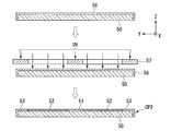
- the cleaning sequence is executed using the cleaning substrate CP.
- the cleaning substrate CP is a substrate used for cleaning the liquid immersion member.
- the liquid immersion member may be the liquid immersion member 7 described in the first embodiment, or may be another liquid immersion member.
- the cleaning substrate CP of this embodiment is also an aspect of the dummy substrate according to this embodiment.
- a cleaning process may be executed for members that do not come into contact with the exposure liquid LQ.
- FIG. 5A is a plan view showing an example of the cleaning substrate of the present embodiment
- FIG. 5B is a cross-sectional view showing an example of the cleaning substrate.
- FIG. 5B corresponds to a cross-sectional view taken along line A-A ′ of FIG. 5A.
- the cleaning substrate CP is disposed at a position facing the liquid immersion member 7 in at least a part of the cleaning sequence of the liquid immersion member 7.
- a plan view from the Z-axis direction may be simply referred to as a plan view.
- the relative position between the liquid immersion member 7 and the cleaning substrate CP is adjusted so that the opening 7K of the liquid immersion member 7 is accommodated inside the outer edge of the first liquid repellent portion 51 of the cleaning substrate CP in plan view.
- Sometimes referred to as an alignment state. 5A and 5B show the cleaning substrate CP in the aligned state.
- the outer edge of the first liquid repellent portion 51 of the cleaning substrate CP in plan view faces the lower surface 15B of the plate portion 15 in the aligned state.
- the cleaning substrate CP of the present embodiment includes a substrate body 50, a first liquid repellent part 51, a lyophilic part 52, a second liquid repellent part 53, and notches 55a to 55c provided in the outer edge part 54.
- the lyophilic portion and the lyophobic portion of the cleaning substrate CP of the present embodiment are compatible with a predetermined liquid defined by a distribution and / or a contact angle that can perform a cleaning operation (non-exposure operation) of the exposure apparatus EX. It has sex.
- the contact angle of the lyophilic part with respect to the predetermined liquid, and the contact angle of the liquid repellent part with respect to the predetermined liquid is the exposure apparatus EX. It may be determined in association with the cleaning operation (non-exposure operation).
- the predetermined liquid is a liquid (including a cleaning liquid LC) used for a cleaning operation that is one of the non-exposure operations.
- the outer shape and size of the cleaning substrate CP of this embodiment are substantially the same as the outer shape and size of the substrate P.
- the substrate body 50 is a base material for the cleaning substrate CP.
- the substrate body 50 includes, for example, a plate member such as a metal substrate, a silicon substrate, a glass substrate, or a quartz substrate, or a composite member obtained by bonding two or more plate members.
- a plate member such as a metal substrate, a silicon substrate, a glass substrate, or a quartz substrate, or a composite member obtained by bonding two or more plate members.
- the cleaning substrate CP may have a larger area than the substrate P, or may have a smaller area.
- the surface of the first liquid repellent part 51 is liquid repellent with respect to the first cleaning liquid LC1.
- the contact angle of the first cleaning liquid LC1 with respect to the first liquid repellent portion 51 may be 80 degrees or more, 90 degrees or more, 100 degrees or more, 110 degrees or more, or 120 degrees or more. In the present embodiment, the contact angle of the first cleaning liquid LC1 with respect to the first liquid repellent part 51 is set to a range of 95 degrees or more.
- the surface of the first liquid repellent part 51 may be flat, may have irregularities, may have slopes, or may have a curved surface.
- the surface of the first liquid repelling part 51 of this embodiment has liquid repellency with respect to the second cleaning liquid LC2.
- the contact angle of the second cleaning liquid LC2 with respect to the first liquid repellent part 51 may be 80 degrees or more, 90 degrees or more, 100 degrees or more, 110 degrees or more, or 120 degrees or more.
- the contact angle of the second cleaning liquid LC2 with respect to the first liquid repellent part 51 is set to a range of 95 degrees or more.
- the surface of the first liquid repellent portion 51 of this embodiment has liquid repellency with respect to the rinse liquid LH.
- the contact angle of the rinsing liquid LH with respect to the first liquid repellent portion 51 may be 80 degrees or more, 90 degrees or more, 100 degrees or more, 110 degrees or more, or 120 degrees or more. In the present embodiment, the contact angle of the rinsing liquid LH with respect to the first liquid repellent part 51 is set to a range of 95 degrees or more.
- the contact angles of the first cleaning liquid LC1, the second cleaning liquid LC2, and the rinsing liquid LH2 with respect to the first liquid repellent part 51 may be different from each other.
- the contact angle of the first cleaning liquid LC1 with respect to the first liquid repellent part 51 is set to 100 degrees or more
- the contact angle of the second cleaning liquid LC2 with respect to the first liquid repellent part 51 is set to 80 degrees or more. It doesn't matter.
- the first liquid repellent portion 51 may have liquid repellency only in at least one of the first cleaning liquid LC1, the second cleaning liquid LC2, and the rinsing liquid LH.
- the first liquid repellent portion 51 may include a liquid repellent member (including a liquid repellent film) provided on the substrate body 50.
- the liquid repellent member is formed of a liquid repellent material having liquid repellency with respect to the first cleaning liquid LC1 and the second cleaning liquid LC2.
- the liquid repellent material may be, for example, any of a material containing titanium, a material containing fluorine, a material containing silicon carbonitride, or a combination of two or more of these materials.
- the material containing fluorine is, for example, a fluorine-containing resin (fluorine-based resin), and may be polytetrafluoroethylene (PFA) or polytetrafluoroethylene (PTFE).
- the liquid repellent member may include a member formed of a material containing titanium and a film formed of a material containing fluorine on the member.
- the first liquid repellent part 51 may include a part of the substrate body 50.
- the liquid repellent treatment for imparting liquid repellency to the substrate body 50 may be a surface treatment using a coupling material for imparting an alkyl group to the surface to be treated, for example.
- liquid repellency can be imparted to the surface of the silicon substrate by applying a silane coupling material to the surface of the silicon substrate.
- the first liquid repellent portion 51 may include a portion where the liquid repellent member is subjected to a liquid repellent treatment.
- the surface of the lyophilic part 52 with respect to the first cleaning liquid LC1 is lower than the liquid repellency of the surface of the first liquid repelling part 51 with respect to the first cleaning liquid LC1.
- the lyophilic part 52 of the present embodiment is lyophilic with respect to the first cleaning liquid LC1.
- the lyophilic part 52 of the present embodiment has a lyophilic property equivalent to that of the first cleaning liquid LC1 with respect to the second cleaning liquid LC2.
- the contact angles of the first cleaning liquid LC1 and the second cleaning liquid LC2 with respect to the lyophilic part 52 are smaller than the contact angles of the first cleaning liquid LC1 and the second cleaning liquid CL2 with respect to the first liquid repellent part 51.
- the lyophilic part 52 may include a lyophilic member (including a lyophilic film) provided on the substrate body 50.
- the lyophilic member may be formed of a material having lyophilicity with respect to the cleaning liquid LC. Note that the contact angle of the first cleaning liquid LC1 with respect to the lyophilic part 52 may be larger or smaller than the contact angle of the second cleaning liquid LC2 with respect to the lyophilic part 52.
- the contact angle of the first cleaning liquid LC1 with respect to the lyophilic portion 52 may be 40 degrees or less, 30 degrees or less, 20 degrees or less, or 10 degrees or less. In the present embodiment, the contact angle of the first cleaning liquid LC1 with respect to the lyophilic part 52 is set to a range of 30 degrees or less. In the present embodiment, the contact angle of the second cleaning liquid LC2 with respect to the lyophilic part 52 may be 40 degrees or less, 30 degrees or less, 20 degrees or less, or 10 degrees or less. In the present embodiment, the contact angle of the first cleaning liquid LC1 with respect to the lyophilic part 52 is set to a range of 30 degrees or less.
- the contact angle of the rinsing liquid LH with respect to the lyophilic part 52 may be 40 degrees or less, 30 degrees or less, 20 degrees or less, or 10 degrees or less. In the present embodiment, the contact angle of the rinsing liquid LH with respect to the lyophilic part 52 is set to a range of 30 degrees or less.
- the contact angles of the first cleaning liquid LC1, the second cleaning liquid LC2, and the rinsing liquid LH with respect to the lyophilic portion 52 may be different from each other.
- the contact angle of the first cleaning liquid LC1 with respect to the lyophilic part 52 may be larger or smaller than the contact angle of the second cleaning liquid LC2 with respect to the lyophilic part 52.
- the contact angle of the first cleaning liquid LC1 to the lyophilic part 52 when the contact angle of the first cleaning liquid LC1 to the lyophilic part 52 is set to 30 degrees or less, the contact angle of the second cleaning liquid LC2 to the lyophilic part 52 may be set to 40 degrees or less.
- the lyophilic part 52 may have lyophilic properties only in at least one of the first cleaning liquid LC1, the second cleaning liquid LC2, and the rinsing liquid LH.
- a part of the substrate body 50 may be used as the lyophilic portion 52.
- the lyophilic part 52 may include a part of the substrate body 50 and may not include a separate member from the substrate body 50.
- the lyophilic portion 52 may include a recess formed in the substrate body 50 by, for example, etching or cutting.
- the lyophilic treatment for imparting lyophilicity to the substrate body 50 may be, for example, a surface treatment that exposes the surface to be treated to oxygen plasma, or a surface treatment that imparts hydroxyl groups (—OH) to the surface to be treated. May be.
- the liquid repellency of the surface of the second liquid repellent part 53 with respect to the first cleaning liquid LC1 is higher than the liquid repellency of the surface of the lyophilic part 52 with respect to the first cleaning liquid LC1.
- the liquid repellency of the surface of the second liquid repellent part 53 with respect to the second cleaning liquid LC2 is higher than the liquid repellency of the surface of the lyophilic part 52 with respect to the second cleaning liquid LC2.
- the second liquid repellent portion 53 may have liquid repellency with respect to the first cleaning liquid LC1 or may have lyophilicity with respect to the first cleaning liquid LC1.
- the second liquid repellent portion 53 may have liquid repellency with respect to the second cleaning liquid LC1 or may have lyophilicity with respect to the second cleaning liquid LC2.
- the contact angle of the first cleaning liquid LC1 with respect to the first liquid repellent part 51 may be the same as or different from the contact angle of the first cleaning liquid LC1 with respect to the second liquid repellent part 53.
- the contact angle of the second cleaning liquid LC2 with respect to the first liquid repellent part 51 may be the same as or different from the contact angle of the second cleaning liquid LC2 with respect to the second liquid repellent part 53.
- the contact angles of the first cleaning liquid LC1 and the second cleaning liquid LC2 with respect to the second liquid repellent part 53 are substantially the same as the contact angles of the first cleaning liquid LC and the second cleaning liquid LC2 with respect to the first liquid repellent part 51.
- the second liquid repellent part 53 may include a liquid repellent member or may include a part of the substrate body 50 that has been subjected to the liquid repellent treatment.
- the first liquid repellent part 51 and the second liquid repellent part 53 may be made of the same material or different materials.
- the second liquid repellent part 53 of the present embodiment has substantially the same liquid repellency with respect to the first cleaning liquid LC1 as the liquid repellent part 24 of the liquid immersion member 7.
- the material of the second liquid repellent part 53 of the embodiment is the same as that of the liquid repellent part 24 of the liquid immersion member 7.
- the shape and dimensions of the first liquid repellent portion 51 of the present embodiment are set so that the opening 7K of the liquid immersion member 7 is accommodated inside the outer edge.
- the planar view from the plate thickness direction (Z-axis direction) of the liquid immersion member 7 hereinafter simply referred to as a planar view).
- the shape and dimensions of the first liquid repellent part 51 are set so that the opening 7K can be accommodated inside the outer edge of the first liquid repellent part 51.
- the first liquid repellent portion 51 of the present embodiment is a region surrounded by the outer edge.
- the region surrounded by the outer edge of the first liquid repellent part 51 is larger than the opening 7 ⁇ / b> K of the liquid immersion member 7.
- the region surrounded by the outer edge of the first liquid repellent portion 51 is smaller than the region surrounded by the liquid recovery port 20 on the lower surface 14 of the liquid immersion member 7.
- the area surrounded by the outer edge of the first liquid repellent part 51 may be larger than the area surrounded by the liquid recovery port 20 on the lower surface 14 of the liquid immersion member 7.
- the area surrounded by the outer edge of the first liquid repellent portion 51 may be the same size as the area surrounded by the liquid recovery port 20 on the lower surface 14 of the liquid immersion member 7.
- the outer edge of the first liquid repellent part 51 may be the same as the outer shape of the lower surface 15B of the plate part 15. Further, the region surrounded by the first liquid repellent portion 51 may be the same as the region surrounded by the outer shape of the lower surface 15B of the plate portion 15. Further, the outer edge of the first liquid repellent portion 51 may be larger or smaller than the outer shape of the lower surface 15B of the plate portion 15. Further, the region surrounded by the first liquid repellent portion 51 may be wider or narrower than the region surrounded by the outer shape of the lower surface 15B of the plate portion 15.
- the region of the cleaning substrate CP facing the opening 7K of the liquid immersion member 7 varies depending on the relative position between the liquid immersion member 7 and the cleaning substrate CP. That is, the region facing the opening 7K of the liquid immersion member 7 is determined according to the position of the opening 7K.
- the region facing the opening 7 ⁇ / b> K of the liquid immersion member 7 in the cleaning substrate CP is the inside 51 a of the first liquid repellent portion 51.
- the region facing the opening 7 ⁇ / b> K of the liquid immersion member 7 can be surrounded by the outer edge of the first liquid repellent portion 51.
- the outer edge of the first liquid repellent portion 51 of the cleaning substrate CP faces the lower surface 15B.
- the lyophilic part 52 is provided so as to surround the first liquid repellent part 51.
- the lyophilic part 52 of the present embodiment surrounds the first liquid repellent part 51 in an annular shape.
- the shape and dimensions of the lyophilic part 52 are set so that at least a part of the liquid recovery port 20 of the liquid immersion member viewed in plan in the aligned state overlaps the lyophilic part 52.
- the lyophilic portion 52 is larger than the liquid recovery port 20 of the liquid immersion member 7 in the diameter direction of the cleaning substrate CP (for example, in AA ′. In the present embodiment, in the aligned state.
- the shape and dimensions of the lyophilic part 52 are set so that the entire second supply port 22 faces the lyophilic part 52.
- the alignment shown in FIGS. In this state, the liquid (LC1, LC2, LH) is suppressed from flowing from the lyophilic part 52 to the first liquid repellent part 51.
- the first liquid repellent part 51 is disposed so as to surround the optical path K. Then, when the liquid (LC1, LC2, LH) is supplied between the liquid immersion member 7 and the lyophilic part 52, the liquid (LC1, LC2, LH) is suppressed from passing through the opening 7K.
- the liquid immersion The liquid (LC1, LC2, LH) supplied between the material 7 and the lyophilic part 52 is prevented from flowing into the space between the liquid immersion member 7 and the first liquid repellent part 51.
- the liquid (LC1, LC2, LH) is prevented from flowing from the space below the opening 7K (the space on the lower surface 15B side) into the space above the opening 7K (the space on the upper surface 15A side).
- the second liquid repellent part 53 is provided so as to surround the lyophilic part 52.
- the second liquid repellent portion 53 of the present embodiment surrounds the lyophilic portion 52 in an annular shape.
- the shape and dimensions of the second liquid repellent part 53 are set so that the second liquid repellent part 53 viewed in plan in the aligned state does not face the second supply port 22.
- the shape and dimensions of the second liquid repellent part 53 are set so that at least a part of the second liquid repellent part 53 viewed in plan in the aligned state faces the liquid repellent part 24 of the liquid immersion member 7. Has been.
- the notches 55a to 55c of the present embodiment are provided in association with the non-exposure operation of the exposure apparatus EX.
- at least one of the number of notches 55a to 55c, the shapes of the notches 55a to 55c, and the positions of the notches 55a to 55c on the outer edge portion 54 of the cleaning substrate CP is used for the non-exposure operation of the exposure apparatus EX. Is set accordingly.
- the shapes of the notches 55a to 55c may be the same or different from each other.
- the cleaning substrate CP may include a position detection notch indicating the position on the cleaning substrate CP.
- the notch for position detection may be provided, for example, in an orientation or position associated with the crystal direction of the substrate.
- the notches 55a to 55c may be provided separately from the notches for position detection described above, or may include notches for position detection.
- a notch is set in the outer edge portion of the cleaning substrate CP according to the non-exposure operation of the exposure apparatus EX.
- the cleaning substrate CP to be set is not limited to the substrate of the present embodiment.
- the substrate used for the non-exposure operation may have only one type of liquid repellent portion. Thereby, it is possible to collate the notch detection result mentioned later and non-exposure operation.
- the cleaning substrate CP of the present embodiment may include only a position detection notch or may not include a notch.
- the cleaning substrate CP may include an identifier associated with the non-exposure operation of the exposure apparatus EX, and this identifier may be other than the notch. This identifier may be a barcode.
- the dummy substrate of this embodiment is applicable also to the dummy substrate used for non-exposure operations other than cleaning. That is, the dummy substrate may be provided with a notch associated with a non-exposure operation other than cleaning at the outer edge portion. Thereby, it is possible to collate the notch detection result mentioned later and non-exposure operation.
- the substrate body 50 of this embodiment uses a silicon substrate as a base material.
- the first liquid repellent portion 51 of the present embodiment includes a polytetrafluoroethylene plate member (liquid repellent member).
- the thickness of the plate member of the first liquid repellent part 51 may be set according to the gap between the lower surface 14 and the cleaning substrate CP when the lower surface 14 of the liquid immersion member 7 and the cleaning substrate CP are opposed to each other.
- the second liquid repellent portion 53 of the present embodiment includes a polytetrafluoroethylene plate member (liquid repellent member).
- the lyophilic part 52 of this embodiment includes a substrate body 50 between the first liquid repellent part 51 and the second liquid repellent part 53.
- the surface of the first liquid repellent part 51 and the surface of the lyophilic part 52 have a step according to the thickness of the liquid repellent member and the lyophilic member.
- the above step is a step corresponding to the thickness of the liquid repellent member and the depth of the recess.
- the first liquid repellent portion 51 of the present embodiment protrudes from the lyophilic portion 52 in the plate thickness direction (normal direction) of the substrate body 50.
- the first liquid repellent portion 51 of the present embodiment is a convex portion with respect to the lyophilic portion 52 toward the outside of the substrate body 50.
- the distance between the first liquid repellent part 51 and the lower surface 15B is shorter than the distance between the lyophilic part 52 and the lower surface 15B.
- the surface of the second liquid repellent part 53 and the surface of the lyophilic part 52 have a step according to the thickness of the liquid repellent member and the lyophilic member.
- the above step is a step corresponding to the thickness of the liquid repellent member and the depth of the recess.
- the second liquid repellent portion 53 of the present embodiment protrudes from the lyophilic portion 52 in the thickness direction of the substrate body 50.
- the second liquid repellent portion 53 of the present embodiment is a convex portion with respect to the lyophilic portion 52 toward the outside of the substrate body 50.
- the step between the first lyophobic part 51 and the lyophilic part 52 and the step between the lyophilic part 52 and the second lyophobic part 53 are set within a range of 0.03 mm to 0.3 mm. Has been.
- the step between the surface of the first liquid repellent part 51 and the surface of the lyophilic part 52 and the step between the surface of the second liquid repellent part 51 and the surface of the lyophilic part 52 may be different.
- the part from which the 1st liquid repellent part 51 differs in liquid repellency may be arrange
- the first liquid repellent part 51 may be provided in an annular shape, and the part surrounded by the first liquid repellent part may include a liquid repellent or non-liquid repellent part.
- Non-liquid repellency includes lyophilicity.
- the cleaning substrate CP may include a lyophilic part that is more lyophilic than the first liquid repellent part 51 in the portion surrounded by the first liquid repellent part 51.
- the cleaning substrate CP may not include the second liquid repellent portion 53.
- the shape of the outer edge of the first liquid repellent portion 51 is not limited to a rectangle.
- the shape of the outer edge of the first liquid repellent portion 51 is any one of a circle, an ellipse, a polygon, a shape obtained by rounding some corners of the polygon, a shape whose outline is a free curve, and a shape obtained by combining these shapes. There may be. Further, the first liquid repellent part 51 and the lyophilic part 52 may not have a step. Further, there may be no step between the lyophilic portion 52 and the second lyophobic portion 53.
- a part of the liquid recovery port 20 in a plan view in the aligned state is opposed to the lyophilic part 52, and the liquid recovery port 20 is changed partly by changing the relative position of the liquid immersion member 7 and the cleaning substrate CP. It may be possible to face the lyophilic part 52 sequentially. For example, by rotating the cleaning substrate CP around the Z-axis direction in the aligned state, the entire liquid recovery port 20 can be opposed to the lyophilic portion 52 in time sequence while maintaining the aligned state. There may be.
- a liquid repellent part between the first liquid repellent part 51 and the second liquid repellent part 53 there may be a liquid repellent part between the first liquid repellent part 51 and the second liquid repellent part 53.
- a liquid repellent part that extends in the radial direction from the center of the cleaning substrate CP may be disposed around the first liquid repellent part 51 between the first liquid repellent part 51 and the second liquid repellent part.
- the liquid repellent part extending in the radial direction between the first liquid repellent part 51 and the second liquid repellent part may be connected to at least one of the first liquid repellent part 51 and the second liquid repellent part. However, it does not have to be connected.
- the second liquid repellent portion 53 of the cleaning substrate CP may not be formed.
- the liquid (including at least one of the first cleaning liquid LC1, the second cleaning liquid LC2, and the rinsing liquid LH) that flows out from the upper surface of the cleaning substrate CP is removed from the gap between the cover member T and the cleaning substrate CP. It may be allowed to flow into the lower space.
- at least part of at least one of the cover member T and the substrate holding member 11 is caused by the liquid flowing in from the gap (including at least one of the first cleaning liquid LC1, the second cleaning liquid LC2, and the rinse liquid LH). Can be washed.
- a plurality of lyophilic parts 52 may be arranged around the first liquid repellent part 51, and the plurality of lyophilic parts 52 are arranged in the circumferential direction around the optical axis 12A so as to dispose the first liquid repellent part 51. It may be enclosed. Moreover, the contact angle with respect to each water of a some lyophilic part may differ.
- a part of the second supply port 22 in plan view in the aligned state faces the second liquid repellent portion 53, and the relative position between the liquid immersion member 7 and the cleaning substrate CP is changed. It may be possible not to make 22 face the second liquid repellent part 53. For example, by rotating the cleaning substrate CP around the Z-axis direction in the aligned state, the second supply port 22 and the second liquid repellent portion 53 face each other while maintaining the aligned state, It may be possible to switch between the state in which the supply port 22 and the second liquid repellent portion 53 do not face each other.
- the second liquid repellent part 53 and the lyophilic part 52 are discontinuous, and the liquid repellency of the cleaning substrate CP with respect to the cleaning liquid LC is stepwise between the second liquid repellent part 53 and the lyophilic part 52. It may change continuously.
- the dummy substrate may be a substrate used for non-exposure operation using a liquid other than the cleaning liquid LC. This liquid may be the exposure liquid LQ.
- the dummy substrate may be a substrate used for non-exposure operations other than the cleaning operation.
- the dummy substrate may be a substrate used for the measurement operation of the exposure apparatus EX.
- the dummy substrate may be a substrate used for a verification operation for verifying various sensors included in the exposure apparatus EX.
- 6A and 6B are schematic configuration diagrams showing other examples of the cleaning substrate according to the second embodiment, respectively.
- the cleaning substrate CP2 shown in FIG. 6A includes a substrate body 50, a first liquid repellent part 51, a lyophilic part 52, and a second liquid repellent part 53.
- the surface of the first liquid repellent part 51 and the surface of the lyophilic part 52 are substantially flush.
- the surface of the first liquid repellent part 51 and the surface of the lyophilic part 52 are substantially flush.
- the cleaning substrate CP2 of this embodiment is manufactured according to the flow shown in FIG. 6A, for example.
- the substrate body 50 having the liquid repellent film 56 provided on the surface is prepared, and the liquid repellent film 56 is selectively irradiated with light and irradiated with light. This includes reducing the liquid repellency of the region (improving lyophilicity).
- the substrate main body 50 having the liquid repellent film 56 provided on the surface is prepared by forming the liquid repellent film 56 on the surface of the substrate main body 50 using the above-described liquid repellent material.
- the liquid repellent film 56 is formed of a liquid repellent material containing polytetrafluoroethylene (PFA).
- ultraviolet light UV is irradiated onto the liquid repellent film 56 through the photomask 57, and the portion of the liquid repellent film 56 irradiated with the ultraviolet light UV is used as the lyophilic portion 52.
- the photomask 57 of the present embodiment includes an annular light transmitting part and light shielding parts arranged on the inner side and the outer side of the light transmitting part.
- a portion of the liquid repellent film 56 that is not irradiated with the ultraviolet light UV corresponding to the inside of the light transmitting portion of the photomask 57 is defined as the first liquid repellent portion 51.
- the portion of the liquid repellent film 56 that is not irradiated with the ultraviolet light UV corresponding to the outside of the light transmitting portion of the photomask 57 is defined as the first liquid repellent portion 53.
- the cleaning substrate CP3 shown in FIG. 6B includes a substrate body 50, a first liquid repellent part 51, a lyophilic part 52, and a second liquid repellent part 53.
- the substrate body 50 of the present embodiment has a liquid repellency on the surface lower than the liquid repellency on the surface of the first liquid repellent portion 51.
- the substrate body 50 of the present embodiment is a titanium substrate.
- the substrate body 50 may be a silicon substrate.
- the lyophilic part 52 of the basic embodiment includes the surface of the substrate body 50.
- the surface disposed facing the liquid immersion member 7 when cleaning may be irradiated with ultraviolet light before cleaning.
- the ultraviolet light may be light emitted from the same light source as the exposure light EL.
- the ultraviolet light may be light emitted from a light source different from the exposure light EL.
- the substrate body 50 may include a surface made of a material whose liquid repellency reduction amount is greater than that of the first liquid repellent portion 51 when irradiated with ultraviolet light.
- the controller 8 of the exposure apparatus EX controls the liquid system 100 to supply and collect various liquids used for cleaning.
- the control device 8 is a part of the valves 35 to 37, the dilution device 38, the first cleaning liquid supply device 39, the second cleaning liquid supply device 40, the suction device 41, and the detection device 42 of the liquid system 100. Or it can be controlled entirely.
- the controller 8 of the exposure apparatus EX controls the liquid system 100 to supply and collect various liquids used for cleaning.
- the control device 8 is a part of the valves 35 to 37, the dilution device 38, the first cleaning liquid supply device 39, the second cleaning liquid supply device 40, the suction device 41, and the detection device 42 of the liquid system 100. Or it can be controlled entirely.
- FIG. 7 is a flowchart showing an example of the cleaning method of the present embodiment.
- the cleaning substrate CP is carried into the substrate stage 2 in step SA1.
- the first cleaning liquid LC1 for cleaning is supplied between the liquid immersion member 7 and the cleaning substrate CP, and the liquid immersion member 7 is cleaned.
- a rinsing liquid LH for rinsing is supplied to the liquid immersion member 7.
- the second cleaning liquid LC2 for cleaning is supplied between the liquid immersion member 7 and the cleaning substrate CP, and the liquid immersion member 7 is cleaned.
- the rinsing liquid LH is supplied to the liquid immersion member 7. After at least a part of the rinse liquid LH supplied in step SA5 is recovered, the rinse liquid LH is supplied to the liquid immersion member 7 in step SA6.
- the cleaning substrate CP is unloaded from the substrate stage 2.
- the cleaning process (SA2) using the first cleaning liquid LC1 is appropriately referred to as a first cleaning process
- the cleaning process (SA4) using the second cleaning liquid LC2 is appropriately referred to as a second cleaning process.
- the process of supplying the rinsing liquid LH to the member such as the liquid immersion member 7 cleaned using the cleaning liquid LC (LC1, LC2) is appropriately referred to as a rinsing process.
- the rinsing process includes a process of supplying the rinsing liquid LH to the member, rinsing the member, and removing the cleaning liquid LC (LC1, LC2) remaining on the member.
- the rinsing process (SA3) executed after the first cleaning process is appropriately referred to as a first rinsing process
- the rinsing process (SA5) executed after the second cleaning process is appropriately referred to as a second rinsing process
- the rinse process (SA6) executed later is appropriately referred to as a third rinse process.
- An alkaline liquid may be used as the first cleaning liquid LC1. That is, an alkaline solution containing a predetermined substance may be used as the first cleaning liquid LC1.
- the first cleaning liquid LC1 may include tetramethylammonium hydroxide (TMAH) as a predetermined substance.
- TMAH tetramethylammonium hydroxide
- an alkaline aqueous solution may be used as the first cleaning liquid LC1.
- An acidic liquid may be used as the second cleaning liquid LC2. That is, an acidic solution containing a predetermined substance may be used as the second cleaning liquid LC2.
- the second cleaning liquid LC2 may contain hydrogen peroxide as the predetermined substance.
- an acidic aqueous solution may be used as the second cleaning liquid LC2.
- An aqueous solution may be used as the rinse liquid LH. That is, an aqueous solution containing a predetermined substance may be used as the rinse liquid LH. Of course, the predetermined substance may not be included. Alcohol may be included as the predetermined substance. Moreover, you may use alcohol as a rinse liquid. Further, the first cleaning liquid LC1 and the rinsing liquid LH may contain the same type of liquid. Further, the second cleaning liquid LC2 and the rinsing liquid LH may contain the same type of liquid.
- an alkaline aqueous solution is used as the first cleaning liquid LC1.
- a hydrogen peroxide aqueous solution is used as the second cleaning liquid LC2.
- An exposure liquid LQ is used as the rinse liquid LH. That is, the rinse liquid LH of this embodiment is water (pure water).
- the rinse liquid LH of this embodiment is water (pure water).
- Each of the first cleaning liquid LC1, the second cleaning liquid LC2, and the rinsing liquid LH of the present embodiment contains water as the same type of liquid.
- an aqueous tetramethylammonium hydroxide solution is used as the first cleaning liquid LC1.
- an inorganic alkali solution such as aqueous ammonia, sodium hydroxide solution, or potassium hydroxide solution, or an organic alkali solution such as trimethyl (2-hydroxyethyl) ammonium hydroxide may be used.
- an aqueous hydrogen peroxide solution (hydrogen peroxide solution) is used as the second cleaning liquid LC2.
- the second cleaning liquid LC2 may include a buffered hydrofluoric acid solution.
- the second cleaning liquid LC2 may be a solution containing buffered hydrofluoric acid and hydrogen peroxide.
- Buffered hydrofluoric acid (buffered hydrofluoric acid) is a mixture of hydrofluoric acid and ammonium fluoride.
- the mixing ratio may be 5 to 2000 in terms of a volume ratio of 40 wt% ammonium fluoride solution / 50 wt% hydrofluoric acid.
- the mixing ratio of buffered hydrofluoric acid and hydrogen peroxide may be 0.8 to 55 in terms of the hydrogen peroxide / hydrofluoric acid weight ratio.
- an ozone liquid containing ozone or a mixed liquid of hydrogen peroxide and a solution containing ozone may be used.
- At least one of the first cleaning liquid LC1 and the second cleaning liquid LC2 may contain alcohol.
- at least one of the first cleaning liquid LC1 and the second cleaning liquid LC2 may include at least one of ethanol, isopropyl alcohol (IPA), and pentanol.
- the same type of liquid contained in each of the first cleaning liquid LC1 and the second cleaning liquid LC2 may be alcohol, for example.
- at least one of the first cleaning liquid LC1, the second cleaning liquid LC2, and the rinsing liquid LH is disposed so that at least one of the upper surface 2F of the substrate stage 2 and the upper surface 3F of the measurement stage 3 is disposed facing the liquid immersion member 7. Or an object other than the cleaning substrate CP, the dummy substrate, the substrate stage 2 and the measurement stage 3 may be supplied.
- the first cleaning liquid LC1, the second cleaning liquid LC2, and the rinsing liquid LH are supplied to clean the last optical element 12 and the liquid immersion member 7, the first cleaning liquid LC1, the second cleaning liquid LC2, and the rinsing liquid LH are used.
- the object (cleaning substrate CP, substrate stage 2, measurement stage 3, dummy substrate, etc.) facing the liquid immersion member 7 may be changed.
- cleaning the liquid immersion member 7 using the cleaning substrate CP or the like cleaning is performed by changing the type of the cleaning substrate CP or the like in each of the first cleaning liquid LC1, the second cleaning liquid LC2, and the rinsing liquid LH. It doesn't matter.
- the same type of cleaning substrate CP may be used.
- the cleaning substrate CP may be newly changed to the same type of cleaning substrate CP or the like.
- step SA1 of the present embodiment the control device 8 executes a process of loading (loading) the cleaning substrate CP into the substrate stage 2.
- the control device 8 moves the substrate stage 2 to the substrate exchange position.
- the process of carrying out the cleaning substrate CP into the substrate holding unit 11 is executed after the process of carrying out the substrate P from the substrate stage 2 is executed.
- the measurement stage 3 is disposed at a position facing the terminal optical element 12 and the liquid immersion member 7 in a state where the substrate stage 2 is disposed at the substrate replacement position for carrying in the cleaning substrate CP.
- the control device 8 exposes the exposure liquid from the first supply port 21. With the supply of LQ stopped, the exposure liquid LQ is recovered from the liquid recovery port 20 (the hole 19H of the porous member 19) for a predetermined time.
- an object different from the measurement stage 3 may be disposed at a position facing the terminal optical element 12 and the immersion member 7.
- the supply of the exposure liquid LQ may be stopped and the recovery of the exposure liquid LQ from the liquid recovery port 20 may be executed for a predetermined time. Further, after the supply of the exposure liquid LQ is stopped, the exposure liquid LQ remaining in the first internal flow path 21R may be removed when performing the first cleaning process.
- the notches 55a to 55c of the cleaning substrate CP are detected.
- the notches 55a to 55c may be detected optically, or the notches 55a to 55c may be detected by contact with a probe or the like.
- an imaging device that images the notches 55a to 55c may be used, or a detection system that detects light passing through the notches 55a to 55c may be used.
- a notch detection device and a notch detection method for detecting a notch for example, the device and method described in JP-A-63-266850 can be applied.
- the device manufacturing system including the exposure apparatus EX has a notch detection device that detects the notches 55a to 55c.
- the exposure apparatus EX may have a part or all of the notch detection apparatus.
- the detection result of the notch detection device is collated with the scheduled operation of the exposure apparatus EX.
- the control device 8 of the exposure apparatus EX collates the detection result of the detection apparatus with the scheduled operation of the exposure apparatus EX.
- correspondence information indicating correspondence relationships between notch information and various operations of the exposure apparatus EX is stored in the storage unit. This storage unit may be part of the control device 8 or an external device of the control device 8.
- control device 8 When the control device 8 performs the above collation, the control device 8 obtains the correspondence information and compares it with the detection result of the notch detection device. Note that an external device of the exposure apparatus EX that is a part of the device manufacturing system may perform the above collation.
- the method for detecting information related to the non-exposure operation of the cleaning substrate CP is not limited to the notch.
- information regarding the distribution of the liquid repellent portion may be printed on the cleaning substrate CP.
- the information regarding the distribution of the liquid repellent portion of the cleaning substrate CP can be collated from not only the notch but also the printed portion.
- the print portion for example, a barcode that is identified by the thickness of a striped line is used.
- the substrate before being held on the substrate stage 2 or the substrate after being held on the substrate stage 2 is a substrate corresponding to a non-exposure operation scheduled for the exposure apparatus EX. Is performed by the control device 8.
- the non-exposure operation includes, for example, one or more of a substrate measurement operation, a cleaning operation of the exposure apparatus EX, and other maintenance operations of the exposure apparatus EX.
- the detection result of the detection device is displayed on a display panel or the like, and the user may make the above determination. Further, a configuration in which the external device of the exposure apparatus EX that is a part of the device manufacturing system performs the above determination may be used.
- the control device 8 may notify the determination result to the user. When the substrate before being held on the substrate stage 2 or the substrate after being held on the substrate stage 2 is a substrate that does not correspond to the planned non-exposure operation of the exposure apparatus EX, the control device 8 is scheduled. The operation may be stopped.
- step SA1 of the present embodiment when it is determined that the substrate held on the substrate stage 2 is the cleaning substrate CP, the control device 8 continues the cleaning operation.
- the liquid immersion member 7 and the liquid immersion member 7 are arranged so that the opening 7K of the liquid immersion member 7 fits inside the outer edge of the first liquid repellent portion 51 of the cleaning substrate CP when viewed in plan from the Z-axis direction.
- the relative position with respect to the cleaning substrate CP is adjusted (see FIGS. 5A and 5B). In this case, at least a part of the outer edge of the first liquid repellent portion 51 of the cleaning substrate CP faces the lower surface 15B of the liquid immersion member 7.
- the control device 8 adjusts the relative position between the liquid immersion member 7 and the cleaning substrate CP by controlling the position of the substrate stage 2.
- the entire liquid recovery port 20 of the liquid immersion member 7 and the entire second supply port 22 face the lyophilic portion 52 when viewed in plan in the aligned state.
- at least a part of the liquid repellent part 24 of the liquid immersion member 7 faces the second liquid repellent part 53 when viewed in plan in the aligned state.
- the space sandwiched between the liquid repellent portion 24 and the second liquid repellent portion 53 surrounds the space sandwiched between the liquid recovery port 20 and the lyophilic portion 52 in an annular shape around the optical axis 12A.
- step SA2 of the present embodiment all the exposure liquid LQ in the immersion space LS between the last optical element 12 and the liquid immersion member 7 and the object (substrate stage 2, measurement stage 3, dummy substrate, etc.) is collected. Thereafter, the first cleaning process is started.
- at least one of the first cleaning liquid LC1 and the gas is recovered from the third internal channel 20R during at least a part of the period during which the first cleaning liquid LC1 is supplied to the space SP3.
- the first cleaning liquid LC1 is supplied to the space SP3 in parallel with the recovery from the third internal flow path 20R.
- the supply of the first cleaning liquid LC1 and the recovery from the third internal flow path 20R are stopped in a state where at least a part of the liquid immersion member 7 around the space SP3 is in contact with the first cleaning liquid LC1.
- the first cleaning liquid LC1 contains alkali and can remove foreign substances including organic substances present on the surface (the lower surface 14 and the like) of the liquid immersion member 7.
- the supply of the first cleaning liquid LC1 is restarted, and the recovery of the first cleaning liquid LC1 from the third internal flow path 20R is started or restarted.
- the supply of the first cleaning liquid LC1 is stopped at a predetermined timing, and after the first cleaning liquid LC1 between the liquid immersion member 7 and the cleaning substrate CP is collected, the first cleaning process is terminated.
- the foreign matter removed from the surface of the liquid immersion member 7 is recovered from the liquid recovery port 20 together with the first cleaning liquid LC1.
- the first cleaning liquid LC1 recovered from the liquid recovery port 20 flows into the housing member 44.
- the predetermined timing for stopping the supply of the first cleaning liquid LC1 may be after the supply amount of the first cleaning liquid LC1 reaches a predetermined amount.
- the predetermined timing may be after the recovery amount from the liquid recovery port 20 reaches a predetermined amount.
- the predetermined timing may be after the time when the member to be cleaned has contacted the first cleaning liquid LC1 reaches a predetermined time.
- the predetermined timing may be determined based on the detection result of the liquid component recovered from the liquid recovery port 20.
- the predetermined timing may be when the amount of the substance removed by cleaning contained in the recovered first cleaning liquid LC1 becomes equal to or less than a predetermined value.
- the detection result may be a detection result of the detection device 42 of the liquid system 100.
- the first liquid repellent part 51 in the first cleaning process, is disposed outside the region facing the opening 7K, and the lyophilic part 52 is disposed outside the first liquid repellent part 51. Therefore, the immersion space LT1 is formed by the first cleaning liquid LC1 in at least a part of the space SP3 outside the opening 7K.
- the first liquid repellent part 51 can be expected to suppress the outflow of the first cleaning liquid LC1 from the space SP3 to the opening 7K side. Further, since the first liquid repellent part 51 protrudes from the lyophilic part 52, it can be expected that the outflow of the first cleaning liquid LC1 from the space SP3 to the opening 7K side is suppressed.
- the first cleaning liquid LC1 can be supplied only to the surface of the liquid immersion member 7.
- the first liquid repellent part 51 may not be disposed outside the region facing the opening 7K as long as the outflow of the first cleaning liquid LC1 from the space SP3 to the opening 7K side can be suppressed. That is, in FIG. 8A, it may be the same as the region facing the opening 7K or inside the region facing the opening 7K.
- the position of the interface on the liquid immersion member 7 side of the immersion space LT1 with the first cleaning liquid LC1 and the interface on the cleaning substrate CP side can be made different.
- the position of the interface on the cleaning substrate CP side can be formed in a region facing the opening 7K in a state where the interface on the liquid immersion member 7 side is maintained on the surface of the liquid immersion member 7, and the first cleaning liquid LC1 can be formed. Can be prevented from flowing into the opening 7K.
- the area surrounded by the outer edge of the first liquid repellent part 51 may be equal to or smaller than the opening 7 ⁇ / b> K of the liquid immersion member 7.
- the lyophilic portion 52 is disposed outside the first lyophobic portion 51, and the second lyophobic portion 53 is disposed outside the lyophilic portion 52.
- An immersion space LT1 is formed by the first cleaning liquid LC1 in at least a part of the inner space SP3.
- the second liquid repellent part 53 protrudes from the lyophilic part 52, it can be expected to suppress the outflow of the first cleaning liquid LC1 from the space SP3 to the outside.
- the liquid repellent part 24 is disposed outside the liquid recovery port 20, it can be expected that the outflow of the first cleaning liquid LC1 to the outside of the liquid repellent part 24 is suppressed.
- the notches 55a to 55c of the cleaning substrate CP arranged to face the liquid immersion member 7 are detected during the first cleaning process. Therefore, it is possible to suppress the supply of the first cleaning liquid LC1 and the like between the substrate and the liquid immersion member 7 in a state where the substrate that does not correspond to the cleaning operation is misplaced facing the liquid immersion member 7. Can be expected.
- step SA2 static immersion treatment may not be performed, and two or more static immersion treatments may be performed.
- the concentration of the first cleaning liquid LC1 to be supplied may be changed before and after the static immersion treatment.
- the first cleaning liquid LC1 containing the exposure liquid LQ may be supplied from the second supply port 22, and the first cleaning liquid LC1 may be supplied while changing the ratio of the exposure liquid LQ in the first cleaning liquid LC1.
- the ratio of the exposure liquid LQ in the first cleaning liquid LC1 may be increased stepwise or continuously, or may be decreased.
- the first cleaning liquid LC1 between the liquid immersion member 7 and the cleaning substrate CP is vibrated. May be given. By applying vibration to the first cleaning liquid LC1, it can be expected that the first cleaning liquid LC1 spreads over the lyophilic part 52 and that the cleaning of the first cleaning liquid LC1 is enhanced.
- the vibration is applied to the first cleaning liquid LC1 between the liquid immersion member 7 and the cleaning substrate CP
- the first cleaning liquid LC1 to which vibration is applied is supplied between the liquid immersion member 7 and the cleaning substrate CP. It doesn't matter.
- the relative position between the liquid immersion member 7 and the cleaning substrate CP may be changed.
- the relative position of the liquid immersion member 7 and the cleaning substrate CP is set in a direction parallel to the optical axis of the projection optical system PL (Z-axis direction). It may be changed.
- the distance between the liquid immersion member 7 (lower surface 15B) and the cleaning substrate CP may be larger or smaller than the distance between the liquid immersion member 7 (lower surface 15B) and the substrate P during exposure.
- the distance between the liquid immersion member 7 (lower surface 15B) and the cleaning substrate CP and the distance between the liquid immersion member 7 (lower surface 15B) and the substrate P during exposure may be the same.
- the cleaning substrate CP includes the liquid repellent portion 51, and the distance between the liquid immersion member 7 and the cleaning substrate CP is determined by the lower surface 15B of the liquid immersion member 7 and the liquid repellent portion 51 of the cleaning substrate CP. Includes the distance to the top surface.
- the relative position between the liquid immersion member 7 and the cleaning substrate CP when the relative position between the liquid immersion member 7 and the cleaning substrate CP is changed, the relative position between the liquid immersion member 7 and the cleaning substrate CP in a direction (for example, XY plane) intersecting the optical axis of the projection optical system PL. May be changed. Further, when the relative position between the liquid immersion member 7 and the cleaning substrate CP is changed, the relative position is changed in the direction intersecting the optical axis of the projection optical system PL (for example, the X direction) while changing the relative position in the Z-axis direction. The position may be changed.
- the direction in which the relative position changes is the direction in which the relative position of the substrate P is changed with respect to the liquid immersion member 7 during exposure (Y (Axial direction).
- Y Axial direction
- the relative position of the liquid immersion member 7 and the cleaning substrate CP is changed during cleaning, the state where the lower surface 15B of the liquid immersion member 7 and the outer edge of the first liquid repellent portion 51 of the cleaning substrate CP are kept facing each other. Is desirable.
- the relative position between the liquid immersion member 7 and the cleaning substrate CP is changed in the direction parallel to the XY plane, the relative position changes so that the opening 7K in plan view does not move to the outside of the first liquid repellent portion 51. An amount may be set.
- the dimensions of the liquid repellent part 24 so that the lyophilic part 52 does not move to the outside of the liquid repellent part 24 of the liquid immersion member may be set according to the above.
- the dimension of the liquid repellent part 24 in an arbitrary direction in the XY plane may be 0.5 times or more, or 1 or more times the dimension of the first liquid repellent part 51 in this direction.
- the arbitrary direction may be a direction in which the relative position between the liquid immersion member 7 and the cleaning substrate CP is changed during the first cleaning process.
- the liquid repellent part 24 is provided in the liquid immersion member 7, but the liquid repellent part 24 may not be provided in the liquid immersion member 7.
- cleaning liquid LC1 is employ
- the pressure wave generator 60 may be part of the exposure apparatus EX or part of the cleaning substrate CP.
- the pressure wave generator 60 may be an external device of the exposure apparatus EX.
- the pressure wave generating device 60 may be disposed outside the liquid immersion member 7 or may be received by the stage 61 that can support the cleaning substrate CP.
- the stage 61 may be the substrate stage 2 or the measurement stage 3.
- a stirrer that operates according to a change in electric field or magnetic field may be disposed between the liquid immersion member 7 and the cleaning substrate CP, and the first cleaning liquid LC1 may be vibrated by the operation of the stirrer.
- Part or all of the stirrer and the drive device that drives the stirrer may be part of the exposure apparatus EX or the cleaning substrate CP.
- the stirrer and the driving device may be an external device of the exposure apparatus EX.
- the first rinse process is started (step SA3).
- the first rinsing process is started.
- the control device 8 executes the recovery of the first cleaning liquid LC1 from the liquid recovery port 20 (the hole 19H of the porous member 19) for a predetermined time while the supply of the first cleaning liquid LC1 from the second supply port 22 is stopped. Thereby, almost all the first cleaning liquid LC1 between the last optical element 12 and the liquid immersion member 7 and the cleaning substrate CP is recovered.
- the first cleaning liquid LC1 may be recovered from the second supply port 22.
- the first cleaning liquid LC1 remaining in the second internal flow path 22R may be removed when the first rinsing process is performed.
- the exposure liquid LQ may be supplied to the second internal flow path 22R to remove the first cleaning liquid LC1 remaining in the second internal flow path 22R.
- FIGS. 9A, 9B, and 9C are diagrams illustrating an example of a state in which the first rinse process is being performed. Also in the first rinsing process, the cleaning substrate CP is disposed facing the liquid immersion member 7. The controller 8 starts supplying the rinsing liquid LH in order to rinse the liquid immersion member 7 with the rinsing liquid LH. Note that the supply of the rinsing liquid LH may be started in a state in which the immersion space LT1 for the first cleaning liquid LC1 is formed.
- the opening 7K and the first liquid repellent part 51 are compared with each other in comparison with the supply of the first cleaning liquid LC1 between the lyophilic part 52 and the liquid immersion member 7.
- the rinse liquid LH is supplied between the liquid immersion member 7 and the lyophilic part 52 in a state where the positions are different.
- the control device 8 adjusts the relative position between the liquid immersion member 7 and the cleaning substrate CP.
- the relative position of the liquid immersion member 7 and the cleaning substrate CP is adjusted so that at least a part of the opening 7K is disposed outside the first liquid repellent part 51 when viewed in plan.
- the relative position of the liquid immersion member 7 and the cleaning substrate CP is adjusted so that at least a part of the opening 7K faces the lyophilic portion 52.
- the control device 8 supplies the rinse liquid LH from the first supply port 21 to the space SP1 in a state where the supply of the first cleaning liquid LC1 from the second supply port 22 is stopped.
- the exposure liquid LQ is used as the rinse liquid LH.
- the liquid from the liquid recovery port 20 (including at least one of the first cleaning liquid LC1 and the rinse liquid LH). Recovery is performed. Thereby, an immersion space LT2 is formed with the rinsing liquid LH between the last optical element 12 and the liquid immersion member 7 and the cleaning substrate CP.
- the surface of the liquid immersion member 7 is rinsed with the rinse liquid LH.
- the rinse liquid LH can remove the first cleaning liquid LC1 remaining on the surface of the liquid immersion member 7.
- the rinsing liquid LH can remove foreign substances adhering to the liquid immersion member 7.
- the liquid recovery port 20 recovers the rinsing liquid LH supplied from the first supply port 21 to at least a part of the surface of the liquid immersion member 7.
- the first cleaning liquid LC1 removed from the surface of the liquid immersion member 7 is recovered from the liquid recovery port 20 together with the rinse liquid LH.
- the rinsing liquid LH is supplied even when the relative position between the liquid immersion member 7 and the cleaning substrate CP is changed as compared with the start of the supply of the rinsing liquid LH.
- the relative position between the liquid immersion member 7 and the cleaning substrate CP is changed in a direction crossing the irradiation direction of the exposure light EL.
- the relative position between the liquid immersion member 7 and the cleaning substrate CP is changed in a direction parallel to the XY plane.
- the liquid immersion member 7 so that the liquid immersion member 7 of the portion 62 (see FIG.
- the rinsing liquid LH facing the portion 62 facing the lyophilic portion 52.
- the supply of the rinsing liquid LH is stopped before the change in the relative position between the liquid immersion member 7 and the cleaning substrate CP, and the supply of the rinsing liquid LH is restarted after the change.
- the rinsing liquid LH may be supplied while changing the relative position between the liquid immersion member 7 and the cleaning substrate CP. Compared with the supply of the first cleaning liquid LC1 between the lyophilic part 52 and the liquid immersion member 7, the rinse liquid LH is changed in a state where the relative positions of the liquid immersion member 7 and the cleaning substrate CP in the Z-axis direction are different. You may supply.
- the rinsing liquid LH may be supplied in a state where the distance between the liquid immersion member 7 and the cleaning substrate CP is wider than when the first cleaning liquid LC1 is being supplied between the lyophilic portion 52 and the liquid immersion member 7. Further, the rinse liquid LH between the liquid immersion member 7 and the cleaning substrate CP may be vibrated.
- the rinse liquid LH may be vibrated using the same apparatus and method as those used when the first cleaning liquid LC1 is vibrated. As shown in FIG. 9C, the rinsing liquid LH may be supplied from the second supply port 22.
- the relative position of the liquid immersion member 7 and the cleaning substrate CP may be changed depending on whether the rinse liquid LH is supplied from the second supply port 22 or the cleaning liquid LC is supplied from the second supply port 22. For example, the relative position in the Z-axis direction may be different between when the rinsing liquid LH is supplied from the second supply port 22 and when the cleaning liquid LC is supplied from the second supply port 22. Further, the rinsing liquid LH may be supplied from the first supply port 21 and the second supply port 22.
- the supply of the rinsing liquid LH is stopped at a predetermined timing, and the first rinsing process is terminated.
- the predetermined timing for stopping the supply of the rinse liquid LH may be after the supply amount of the rinse liquid LH reaches a predetermined amount.
- the predetermined timing may be after the recovery amount from the liquid recovery port 20 reaches a predetermined amount.
- the predetermined timing may be after the time when the member to be cleaned has contacted the rinsing liquid LH reaches a predetermined time.
- the predetermined timing may be determined based on the detection result of the liquid component recovered from the liquid recovery port 20.
- the predetermined timing may be after the amount (concentration) of the first cleaning liquid LC1 contained in the recovered liquid becomes equal to or less than a predetermined value.
- the detection result may be a detection result of the detection device 42 of the liquid system 100.
- the first rinsing process is continued until the concentration of alkali (tetramethylammonium hydroxide) contained in the rinsing liquid LH recovered from the liquid recovery port 20 becomes 1% or less.
- the control device 8 starts the second cleaning process (step SA4).
- the control device 8 starts supplying the second cleaning liquid LC2 in order to clean the liquid immersion member 7 with the second cleaning liquid LC2.
- the parallel operation of the supply of the rinse liquid LH from the first supply port 21 and the recovery of the rinse liquid LH from the liquid recovery port 20 until the supply of the second cleaning liquid LC2 to the liquid immersion member 7 is started. Is executed. That is, the supply of the second cleaning liquid LC2 is started in a state where the immersion space LT2 for the rinsing liquid LH is formed. The supply of the second cleaning liquid LC2 may be started after the rinsing liquid LH between the last optical element 12 and the liquid immersion member 7 and the cleaning substrate CP has been collected. When the second cleaning process is executed after the supply of the rinsing liquid LH is stopped, the rinsing liquid LH remaining in the first internal flow path 21R may be removed.
- the second cleaning liquid LC2 is supplied from the second supply port 22 to the space SP3 with the supply of the rinsing liquid LH from the first supply port 21 stopped.
- the second cleaning liquid LC2 is supplied in a state where the cleaning substrate CP is disposed facing the liquid immersion member 7.
- the relative position between the liquid immersion member 7 and the cleaning substrate CP so that the opening 7K of the liquid immersion member 7 is accommodated inside the outer edge of the first liquid repellent portion 51 of the cleaning substrate CP when viewed in plan. Is adjusted (see FIGS. 5A and 5B), the supply of the second cleaning liquid LC2 is started.
- the control device 8 starts supplying the second cleaning liquid LC2 after adjusting the relative position between the liquid immersion member 7 and the cleaning substrate CP by controlling the position of the substrate stage 2.
- FIG. 10A is a diagram illustrating an example of a state in which the second cleaning process is being performed.
- the recovery of the second cleaning liquid LC2 from the liquid recovery port 20 is executed in parallel with the supply of the second cleaning liquid LC2 from the second supply port 22.
- the immersion space LT3 is formed by the second cleaning liquid LC2 in at least a part of the space SP3 outside the opening 7K.
- the immersion space LT3 is formed by the second cleaning liquid LC2 in at least a part of the space SP3 inside the second liquid repellent part 53.
- the second cleaning liquid LC2 contacts at least a part of the surface of the liquid immersion member 7 including the lower surface 14.
- the surface of the liquid immersion member 7 is cleaned with the second cleaning liquid LC2.
- the dilution device 38 of the liquid system 100 shown in FIG. 4 dilutes the second cleaning liquid LC2 from the second cleaning liquid supply device 40 with the exposure liquid LQ.
- the second cleaning liquid LC2 delivered from the second cleaning liquid supply device 40 is an aqueous solution having a hydrogen peroxide concentration of 30%.
- the dilution device 38 dilutes the second cleaning liquid LC2 with the exposure liquid (water) LQ to generate an aqueous solution having a hydrogen peroxide concentration of 5%.
- an aqueous solution having a hydrogen peroxide concentration of 5% is supplied to the second supply port 22 as the second cleaning liquid LC2.
- the concentration of hydrogen peroxide contained in the second cleaning liquid LC2 is not limited to the above numerical example, and is adjusted to a predetermined concentration suitable for cleaning.
- the concentration of hydrogen peroxide contained in the second cleaning liquid LC2 may not be 5%, and may be, for example, 10% or more, 15% or more, or 20% or more.
- the concentration of hydrogen peroxide contained in the second cleaning liquid LC2 may be set according to the resistance of the part that can be contacted by the second cleaning liquid LC2.
- the portion that can be contacted by the second cleaning liquid LC2 may be one or more members included in the liquid system 100 or the exposure apparatus EX.
- the portion that can be contacted by the second cleaning liquid LC2 may be at least a portion of the cleaning substrate CP.
- a liquid (pure water) supplied from a supply device different from the supply source LQS may be used as the liquid used for diluting the second cleaning liquid LC2.
- a liquid other than water may be used as the liquid used for diluting the second cleaning liquid LC2.
- the second cleaning liquid LC2 delivered from the second cleaning liquid supply device 40 may not be diluted. Further, the diluting device 38 may be omitted.
- the static immersion process described in the first cleaning process may be performed using the second cleaning liquid LC2 instead of the first cleaning liquid LC1.
- vibration may be applied to the second cleaning liquid LC2 between the liquid immersion member 7 and the cleaning substrate CP using the same apparatus and method as those used to apply vibration to the first cleaning liquid LC1.
- the second cleaning liquid LC2 to which vibration is applied may be supplied between the liquid immersion member 7 and the cleaning substrate CP.
- the second cleaning liquid LC2 contains hydrogen peroxide and can remove foreign substances that could not be removed from the surface of the liquid immersion member 7 by the first cleaning process.
- the second cleaning liquid LC2 can remove the first cleaning liquid LC1 remaining on the surface of the liquid immersion member 7 and the like.
- the second cleaning liquid LC2 can remove the first cleaning liquid LC1 that could not be removed from the surface of the liquid immersion member 7 by the first rinsing process. Therefore, by supplying the second cleaning liquid LC2 so as to come into contact with the liquid immersion member 7, the foreign matters adhering to the liquid immersion member 7 and the first cleaning liquid LC1 are removed.
- the second cleaning liquid LC2 can remove foreign matters that could not be removed from the surface of the liquid immersion member 7 or the like by the first rinsing process.
- the second cleaning liquid LC ⁇ b> 2 supplied from the second supply port 22 to at least a part of the surface of the liquid immersion member 7 is recovered from the liquid recovery port 20.
- the foreign matter removed from the surface of the liquid immersion member 7 is recovered from the liquid recovery port 20 together with the second cleaning liquid LC2.
- the supply of the second cleaning liquid LC2 is stopped at a predetermined timing, and after the second cleaning liquid LC2 between the liquid immersion member 7 and the cleaning substrate CP is collected, the first cleaning process is terminated.
- the foreign matter removed from the surface of the liquid immersion member 7 is recovered from the liquid recovery port 20 together with the first cleaning liquid LC1.
- the second cleaning liquid LC2 recovered from the liquid recovery port 20 flows into the storage member 45.
- the predetermined timing for stopping the supply of the second cleaning liquid LC2 may be after the supply amount of the second cleaning liquid LC2 reaches a predetermined amount.
- the predetermined timing may be after the recovery amount from the liquid recovery port 20 reaches a predetermined amount.
- the predetermined timing may be after the time when the member to be cleaned has contacted the second cleaning liquid LC2 reaches a predetermined time.
- the predetermined timing may be determined based on the detection result of the liquid component recovered from the liquid recovery port 20.
- the predetermined timing may be when the amount of the substance removed by cleaning contained in the recovered second cleaning liquid LC2 becomes a predetermined value or less.
- the detection result may be a detection result of the detection device 42 of the liquid system 100.
- the second rinse process is started (step SA5).
- the second rinsing process is started after all the second cleaning liquid LC2 in the immersion space LT2 has been collected.
- the control device 8 executes the recovery of the second cleaning liquid LC2 from the liquid recovery port 20 (the hole 19H of the porous member 19) for a predetermined time while the supply of the second cleaning liquid LC2 from the second supply port 22 is stopped. Thereby, all the second cleaning liquid LC2 between the liquid immersion member 7 and the cleaning substrate CP is recovered.
- the controller 8 starts supplying the rinsing liquid LH in order to rinse the liquid immersion member 7 with the rinsing liquid LH.
- the supply of the rinsing liquid LH may be started in a state where the immersion space LT2 for the second cleaning liquid LC2 is formed.
- the second cleaning liquid LC2 may be recovered from the second supply port 22.
- a recovery operation from the second supply port 22 may be executed.
- the second cleaning liquid LC2 may be recovered from the first supply port 21.
- FIGS. 10B and 10C are diagrams illustrating an example of a state in which the second rinsing process is being performed. Also in the second rinsing process, the cleaning substrate CP is disposed facing the liquid immersion member 7. In the present embodiment, as compared with the supply of the second cleaning liquid LC2 between the lyophilic part 52 and the liquid immersion member 7, the liquid 7C and the first liquid repellent part 51 have different relative positions. A rinse liquid LH is supplied between the immersion member 7 and the lyophilic portion 52. In the present embodiment, after the second cleaning process is completed, the control device 8 adjusts the relative position between the liquid immersion member 7 and the cleaning substrate CP.
- the relative position of the liquid immersion member 7 and the cleaning substrate CP is adjusted so that at least a part of the opening 7K is disposed outside the first liquid repellent part 51 when viewed in plan. In the present embodiment, the relative position of the liquid immersion member 7 and the cleaning substrate CP is adjusted so that at least a part of the opening 7K faces the lyophilic portion 52.
- the control device 8 supplies the rinsing liquid LH from the first supply port 21 to the space SP1 in a state where the supply of the cleaning liquid LC from the second supply port 22 is stopped.
- the exposure liquid LQ is used as the rinse liquid LH.
- the liquid from the liquid recovery port 20 (including at least one of the first cleaning liquid LC1 and the rinsing liquid LH). Recovery is performed.
- the immersion space LT4 is formed with the rinse liquid LH between the last optical element 12 and the liquid immersion member 7 and the cleaning substrate CP.
- the surface of the liquid immersion member 7 is rinsed with the rinse liquid LH.
- the rinse liquid LH can remove the second cleaning liquid LC2 remaining on the surface of the liquid immersion member 7.
- the rinsing liquid LH can remove foreign substances adhering to the liquid immersion member 7.
- the liquid recovery port 20 recovers the rinsing liquid LH supplied from the first supply port 21 to at least a part of the surface of the liquid immersion member 7.
- the second cleaning liquid LC2 removed from the surface of the liquid immersion member 7 is recovered from the liquid recovery port 20 together with the rinse liquid LH.
- the collected rinse liquid LH flows into the housing member 45.
- the relative position between the liquid immersion member 7 and the cleaning substrate CP in the second rinsing process is similar to that in the first rinsing process compared to when the supply of the rinsing liquid LH is started. Even in the changed state, the rinsing liquid LH is supplied.
- the relative position between the liquid immersion member 7 and the cleaning substrate CP is changed in a direction parallel to the XY plane.
- the liquid immersion member 7 so that the liquid immersion member 7 of the portion 63 (see FIG. 10B) facing the first liquid repellent portion 51 at the start of the supply of the rinsing liquid LH faces the lyophilic portion 52.
- the rinsing liquid LH is supplied with the portion 63 facing the lyophilic portion 52.
- the supply of the rinsing liquid LH is stopped before the change in the relative position between the liquid immersion member 7 and the cleaning substrate CP, and the supply of the rinsing liquid LH is restarted after the change.
- the rinsing liquid LH may be supplied while changing the relative position between the liquid immersion member 7 and the cleaning substrate CP. Compared to when the first cleaning liquid LC1 is supplied between the lyophilic portion 52 of the cleaning substrate CP and the liquid immersion member 7, the relative position in the Z-axis direction of the liquid immersion member 7 and the cleaning substrate CP is different. A rinse liquid LH may be supplied. Compared with the supply of the second cleaning liquid LC2 between the lyophilic part 52 and the liquid immersion member 7, the rinse liquid LH may be supplied in a state where the distance between the liquid immersion member 7 and the cleaning substrate CP is wide. . Further, vibration may be applied to the rinse liquid LH between the liquid immersion member 7 and the cleaning substrate CP.
- the vibration may be applied to the rinsing liquid LH in the second rinsing process using the same apparatus and method as those used to apply the vibration to the first cleaning liquid LC1.
- the rinsing liquid LH may be supplied from the second supply port 22.
- the rinsing liquid LH may be supplied from the first supply port 21 and the second supply port 22.
- the supply of the rinsing liquid LH is stopped at a predetermined timing, and the second rinsing process is terminated.
- the predetermined timing for stopping the supply of the rinse liquid LH may be after the supply amount of the rinse liquid LH reaches a predetermined amount.
- the predetermined timing may be after the recovery amount from the liquid recovery port 20 reaches a predetermined amount.
- the predetermined timing may be after the time when the member to be cleaned has contacted the rinsing liquid LH reaches a predetermined time.
- the predetermined timing may be determined based on the detection result of the liquid component recovered from the liquid recovery port 20.
- the predetermined timing may be after the amount (concentration) of the second cleaning liquid LC2 contained in the recovered liquid becomes equal to or less than a predetermined value.
- the second rinsing process may be continued until the concentration of hydrogen peroxide contained in the rinsing liquid LH recovered from the liquid recovery port 20 becomes 1% or less.
- the detection result may be a detection result of the detection device 42 of the liquid system 100.
- the third rinse process is executed (step SA6).
- the rinse liquid LH recovered from the liquid recovery port 20 is stored in the storage member 45 until the concentration of the second cleaning liquid LC2 included in the rinse liquid LH is equal to or lower than a predetermined concentration.
- the control device 8 supplies the rinse liquid LH from the first supply port 21 and the liquid recovery port.
- the liquid system 100 is controlled such that the rinsing liquid LH recovered from the liquid recovery port 20 flows into the housing member 43 while performing a parallel operation with the recovery of the rinsing liquid LH from 20.
- the control device 8 executes a process for unloading the cleaning substrate CP from the substrate stage 2 (step SA7).
- the control device 8 moves the substrate stage 2 to the substrate replacement position.
- the control device 8 may execute an exposure sequence including an exposure process for the substrate P.
- a stage including a liquid repellent portion and a lyophilic portion for example, a substrate stage, a measurement stage, and other maintenance stages may be used in the same manner as the cleaning substrate CP.
- At least one of the first cleaning process and the second cleaning process can be omitted. Further, the first, second, and third rinsing processes can be omitted. For example, the first rinsing process after the first cleaning process can be omitted.
- the supply of the cleaning liquid LC is not limited to the supply from the second supply port 22.
- it may be supplied from the liquid recovery port 20 or supplied from the first supply port 21.
- the liquid (cleaning liquid LC, rinse liquid LQ, etc.) is supplied from the liquid recovery port 20 (hole 19H), and the liquid supplied from the liquid recovery port 20 is disposed outside the liquid recovery port 20. You may collect
- the cleaning liquid LC supplied from the second supply port 22 may be recovered from the liquid recovery port 20, and the rinse liquid LQ supplied from the liquid recovery port 20 may be recovered from the second liquid supply port 22, or the liquid recovery The cleaning liquid LC supplied from the port 20 may be recovered from the second liquid supply port 22, and the rinse liquid LQ supplied from the second supply port 22 may be recovered from the liquid recovery port 20.
- FIG. 11 is a diagram illustrating an example of the cleaning method of the present embodiment.
- a cleaning substrate CPB which is an aspect of the cleaning substrate is used.
- the lyophilic portion 52 ⁇ / b> B of the cleaning substrate CPB includes the bottom of the recess provided in the substrate body 50.
- the liquid immersion member includes an opening 7K through which exposure light passes and a liquid recovery port 20 disposed at least at a part around the opening 7K.
- a liquid system 100B that supplies a cleaning liquid is used.
- the liquid system 100B has a supply port 64 that can supply the first cleaning liquid LC1.
- the supply port 64 is a member different from the liquid immersion member 7B.
- the member having the supply port 64 is supported by a member different from the liquid immersion member 7B (not shown).
- the first cleaning liquid LC1 is supplied from the supply port 64 between the cleaning substrate CPB and the liquid immersion member 7b.
- the liquid system 100B of the present embodiment is selected from the exposure liquid LQ, the first cleaning liquid LC1 (including the dilution liquid), the second cleaning liquid LC2 (including the dilution liquid), and the mixed liquid of the first cleaning liquid LC1 and the second cleaning liquid LC2.
- the liquid to be supplied can be supplied from the supply port 64.
- the cleaning method of this embodiment includes steps SA1 to SA6 similar to those of the third embodiment.
- the supply port 64 by driving a drive device (not shown), the supply port 64 can be driven and its position can be changed.
- the supply port 64 is inserted between the liquid immersion member 7B and the cleaning substrate CPB. Then, each liquid used for cleaning is supplied from the supply port 64 between the lyophilic portion 52B and the liquid immersion member 7B.
- the immersion space LT1 is formed by the first cleaning liquid LC1 in at least a part of the space SP3 outside the opening 7K, and the inner side of the second liquid repellent part 53 is formed.
- An immersion space LT1 is formed by the first cleaning liquid LC1 in at least a part of the space SP3.
- the immersion space LT3 is formed by the second cleaning liquid LC2 in at least a part of the space SP3 outside the opening 7K, and is more than the second liquid repellent portion 53.
- An immersion space LT3 is formed by the second cleaning liquid LC2 in at least a part of the inner space SP3.
- the supply port 64 was driven, it does not need to drive.
- Each liquid used for cleaning may be supplied from the supply port 64 in a state where the supply port 64 and the lyophilic portion 52B face each other. Further, each liquid used for cleaning may be supplied from the supply port 64 in a state where the supply port 64 and the second liquid repellent portion 53 face each other.
- FIG. 12 is a diagram illustrating an example of the cleaning method of the present embodiment.
- the cleaning substrate CPB which is an aspect of the cleaning substrate according to the present embodiment is used.
- the liquid immersion member an opening 7K through which exposure light passes, a supply port 22C that is disposed at least at a part around the opening 7K and can supply a cleaning liquid, and an opening A liquid immersion member 7C having a liquid recovery port 20 disposed outside the supply port 22C with respect to 7K is used.
- the cleaning method of this embodiment includes steps SA1 to SA6 similar to those of the third embodiment.
- the immersion space LT is formed by the cleaning liquid LC in at least a part of the space SP3 outside the opening 7K, and the space SP3 inside the second liquid repellent portion 53.
- An immersion space LT is formed at least in part by the cleaning liquid LC.
- FIG. 13 is a flowchart illustrating an example of a device manufacturing method.
- a microdevice such as a semiconductor device has a step 201 for designing a function / performance of the microdevice, a step 202 for producing a mask (reticle) based on the design step, a step 203 for producing a substrate which is a substrate of the device,
- the substrate processing step 204 includes a substrate processing (exposure processing) including exposing the substrate with exposure light from the pattern of the mask and developing the exposed substrate, and a device assembly step (dicing process, (Including processing processes such as a bonding process and a packaging process) 205, an inspection step 206, and the like.
- the substrate processing step includes a process of cleaning the liquid immersion member 7 and the like according to the above-described embodiment, and the substrate P is exposed with the exposure light EL using the cleaned liquid immersion member 7 and the like.
- a projection optical system PL in which the optical path on the incident side (object surface side) of the last optical element 12 is filled with the exposure liquid LQ can be employed.
- the exposure liquid LQ is transmissive to the exposure light EL, has a high refractive index with respect to the exposure light EL, and is a photosensitive material (photoresist) that forms the surface of the projection optical system PL or the substrate P.
- Those that are stable to the membrane are preferred.
- hydrofluoroether (HFE), perfluorinated polyether (PFPE), fomblin oil, or the like can be used as the first liquid (exposure liquid LQ).
- various fluids such as a supercritical fluid can be used as the first liquid.
- the substrate P in each of the above-described embodiments not only a semiconductor wafer for manufacturing a semiconductor device but also a glass substrate for a display device, a ceramic wafer for a thin film magnetic head, or an original mask (reticle) used in an exposure apparatus (synthesis) Quartz, silicon wafer) or the like is applied.
- the exposure apparatus EX in addition to the step-and-scan type scanning exposure apparatus (scanning stepper) that scans and exposes the pattern of the mask M by moving the mask M and the substrate P synchronously, the mask M and the substrate P Can be applied to a step-and-repeat type projection exposure apparatus (stepper) in which the pattern of the mask M is collectively exposed while the substrate P is stationary and the substrate P is sequentially moved stepwise.
- stepper step-and-repeat type projection exposure apparatus
- the second pattern With the projection optical system after the reduced image of the second pattern is transferred onto the substrate P using the projection optical system while the first pattern and the substrate P are substantially stationary, the second pattern With the projection optical system, the reduced image of the second pattern may be partially overlapped with the first pattern and collectively exposed on the substrate P (stitch type batch exposure apparatus).
- the stitch type exposure apparatus can be applied to a step-and-stitch type exposure apparatus in which at least two patterns are partially transferred on the substrate P, and the substrate P is sequentially moved.
- two mask patterns are synthesized on a substrate via a projection optical system, and one shot area on the substrate is substantially formed by one scanning exposure.
- the present invention can also be applied to an exposure apparatus that performs double exposure at the same time.
- the present invention can also be applied to proximity type exposure apparatuses, mirror projection aligners, and the like.
- the exposure apparatus EX may be an exposure apparatus that does not include the measurement stage 3.
- the present invention can also be applied to an exposure apparatus that includes a plurality of substrate stages and measurement stages.
- the exposure apparatus EX is of a twin stage type having a plurality of substrate stages without a measurement stage as disclosed in US Pat. No. 6,341,007, US Pat. No. 6,208,407, US Pat. No. 6,262,796, and the like.
- An exposure apparatus may be used.
- the cleaning sequence may be executed with any substrate stage facing the liquid immersion member 7 among the plurality of substrate stages.
- the type of the exposure apparatus EX is not limited to an exposure apparatus for manufacturing a semiconductor element that exposes a semiconductor element pattern on the substrate P, but an exposure apparatus for manufacturing a liquid crystal display element or a display, a thin film magnetic head, an image sensor (CCD). ), An exposure apparatus for manufacturing a micromachine, a MEMS, a DNA chip, a reticle, a mask, or the like.
- the position information of each stage is measured using an interferometer system including a laser interferometer.
- an interferometer system including a laser interferometer.
- the present invention is not limited to this.
- a scale diffiffraction grating
- An encoder system may be used.
- a light transmissive mask in which a predetermined light shielding pattern (or phase pattern / dimming pattern) is formed on a light transmissive substrate is used.
- this mask for example, US Pat. No. 6,778,257.
- a variable shaping mask also called an electronic mask, an active mask, or an image generator
- a pattern forming apparatus including a self-luminous image display element may be provided instead of the variable molding mask including the non-luminous image display element.
- the exposure apparatus provided with the projection optical system PL has been described as an example.
- the present invention can be applied to an exposure apparatus and an exposure method that do not use the projection optical system PL.
- an immersion space can be formed between an optical member such as a lens and the substrate, and the substrate can be irradiated with exposure light through the optical member.
- an exposure apparatus (lithography system) that exposes a line-and-space pattern on a substrate P by forming interference fringes on the substrate P.
- the present invention can also be applied.
- the exposure apparatus EX of the above-described embodiment is manufactured by assembling various subsystems including each component so as to maintain predetermined mechanical accuracy, electrical accuracy, and optical accuracy.
- various optical systems are adjusted to achieve optical accuracy
- various mechanical systems are adjusted to achieve mechanical accuracy
- various electrical systems are Adjustments are made to achieve electrical accuracy.
- the assembly process from the various subsystems to the exposure apparatus includes mechanical connection, electrical circuit wiring connection, pneumatic circuit piping connection and the like between the various subsystems. Needless to say, there is an assembly process for each subsystem before the assembly process from the various subsystems to the exposure apparatus.
- comprehensive adjustment is performed to ensure various accuracies as the entire exposure apparatus.
- the exposure apparatus is preferably manufactured in a clean room where the temperature, cleanliness, etc. are controlled.
Landscapes
- Physics & Mathematics (AREA)
- General Physics & Mathematics (AREA)
- Engineering & Computer Science (AREA)
- Health & Medical Sciences (AREA)
- Epidemiology (AREA)
- Public Health (AREA)
- Plasma & Fusion (AREA)
- Life Sciences & Earth Sciences (AREA)
- Atmospheric Sciences (AREA)
- Environmental & Geological Engineering (AREA)
- Exposure And Positioning Against Photoresist Photosensitive Materials (AREA)
- Exposure Of Semiconductors, Excluding Electron Or Ion Beam Exposure (AREA)
Abstract
クリーニング基板(CP)と、液浸部材(7)とを対向させ、液浸部材(7)をクリーニングする。クリーニング基板(CP)は、クリーニング用の第1洗浄液(LC1)に対して撥液性の第1撥液部(51)と第1撥液部(51)の周囲の少なくとも一部に配置されて第1撥液部(51)よりも親液性の親液部(52)とを有する。
Description
本発明は、クリーニング方法、デバイス製造方法、クリーニング基板、液浸部材、液浸露光装置、及びダミー基板に関する。
本願は、2010年8月4日に出願された特願2010-175810号に基づき優先権を主張し、その内容をここに援用する。
本願は、2010年8月4日に出願された特願2010-175810号に基づき優先権を主張し、その内容をここに援用する。
半導体デバイス等のマイクロデバイスの製造工程において、露光光で基板を露光する露光装置が使用される。露光装置の部材、部品が汚染されると、例えば基板に形成されるパターンに欠陥が生じる等、露光不良が発生し、その結果、不良デバイスが発生する可能性がある。そのため、例えば下記特許文献に開示されているような、露光装置内の所定部材をクリーニングする技術が案出されている。
露光不良の発生を抑制するために、露光装置内の部材をクリーニングすることは有効である。
本発明の態様は、露光不良の発生を抑制できるクリーニング方法、及びクリーニング基板を提供することを目的とする。また本発明の態様は、露光不良の発生を抑制できる液浸部材、及び液浸露光装置を提供することを目的とする。また本発明の態様は、不良デバイスの発生を抑制できるデバイス製造方法を提供することを目的とする。また、本発明の態様は、露光不良の発生を抑制できるダミー基板を提供することを目的とする。
本発明の第1の態様に従えば、液浸露光装置において、基板に照射される露光光が通過する開口を有するとともに露光光の光路の少なくとも一部が第1液体で満たされるように基板との間で第1液体を保持する液浸部材のクリーニング方法であって、クリーニング用の第2液体に対して撥液性の第1部分と第1部分の周囲の少なくとも一部に配置されて第1部分よりも親液性の第2部分とを有する物体と、液浸部材とを対向させることと、液浸部材と物体の第2部分との間に第2液体を供給することと、を含み、液浸部材と第2部分との間に供給された第2液体が開口を通過することを物体の第1部分で抑えつつ、第2液体で液浸部材をクリーニングするクリーニング方法が提供される。
本発明の第2の態様に従えば、第1の態様のクリーニング方法で、液浸部材をクリーニングすることと、クリーニングされた液浸部材と基板との間で第1液体を保持することと、第1液体を介して露光光で基板を露光することと、露光された基板を現像することと、を含むデバイスの製造方法が提供される。
本発明の第3の態様に従えば、液浸露光装置において、基板に照射される露光光が通過する開口及び開口の周囲の少なくとも一部に配置された液体回収口を有するとともに露光光の光路の少なくとも一部が第1液体で満たされるように基板との間で第1液体を保持する液浸部材のクリーニングに用いられるクリーニング基板であって、クリーニング用の第2液体に対して撥液性の第1部分と、第1部分の周囲の少なくとも一部に設けられ、第2液体に対して第1部分よりも親液性の第2部分と、を備え、液浸部材を第2液体でクリーニングするために液浸部材と対向するように配置されたときに、液浸部材と第2部分との間に供給された第2液体が開口を通過することを第1部分が抑制するクリーニング基板が提供される。
本発明の第4の態様に従えば、第1液体を介して露光光で基板を露光する液浸露光装置で用いられ、露光光の光路の少なくとも一部が第1液体で満たされるように基板との間で第1液体を保持する液浸部材であって、露光光が通過する開口と、開口の周囲の少なくとも一部に配置された液体回収口と、開口に対して液体回収口の外側に配置され、クリーニング用の第2液体を供給する供給口と、を備える液浸部材が提供される。
本発明の第5の態様に従えば、第1液体を介して露光光で基板を露光する液浸露光装置であって、第4の態様の液浸部材を備える液浸露光装置が提供される。
本発明の第6の態様に従えば、第5の態様の液浸露光装置を用いて基板を露光することと、露光された基板を現像することと、を含むデバイス製造方法が提供される。
本発明の第7の態様に従えば、液体を介して露光光で基板を露光する液浸露光装置の、基板を露光する露光動作とは異なる非露光動作に用いられるダミー基板であって、外縁部分に非露光動作と関連づけられた切欠を備えるダミー基板が提供される。
本発明の態様によれば、露光不良の発生を抑制できる。また本発明の態様によれば、不良デバイスの発生を抑制できる。
以下、本発明の実施形態について図面を参照しながら説明するが、本発明はこれに限定されない。以下の説明においては、XYZ直交座標系を設定し、このXYZ直交座標系を参照しつつ各部の位置関係について説明する。水平面内の所定方向をX軸方向、水平面内においてX軸方向と直交する方向をY軸方向、X軸方向及びY軸方向のそれぞれと直交する方向(すなわち鉛直方向)をZ軸方向とする。また、X軸、Y軸、及びZ軸まわりの回転(傾斜)方向をそれぞれ、θX、θY、及びθZ方向とする。
<第1実施形態>
第1実施形態について説明する。図1は、本実施形態に係る露光装置EXの一例を示す概略構成図である。本実施形態の露光装置EXは、露光液体LQを介して露光光ELで基板Pを露光する液浸露光装置である。本実施形態では、露光光ELの光路の少なくとも一部が露光液体LQで満たされるように液浸空間LSが形成される。液浸空間は、液体で満たされた部分(空間、領域)である。基板Pは、液浸空間LSの露光液体LQを介して露光光ELで露光される。本実施形態では、露光液体LQとして、水(純水)を用いる。
第1実施形態について説明する。図1は、本実施形態に係る露光装置EXの一例を示す概略構成図である。本実施形態の露光装置EXは、露光液体LQを介して露光光ELで基板Pを露光する液浸露光装置である。本実施形態では、露光光ELの光路の少なくとも一部が露光液体LQで満たされるように液浸空間LSが形成される。液浸空間は、液体で満たされた部分(空間、領域)である。基板Pは、液浸空間LSの露光液体LQを介して露光光ELで露光される。本実施形態では、露光液体LQとして、水(純水)を用いる。
また、本実施形態の露光装置EXは、例えば米国特許第6897963号、及び欧州特許出願公開第1713113号等に開示されているような、基板ステージと計測ステージとを備えた露光装置である。
図1において、露光装置EXは、マスクMを保持して移動可能なマスクステージ1と、基板Pを保持して移動可能な基板ステージ2と、基板Pを保持せずに、露光光ELを計測する計測部材C(計測器)を搭載して移動可能な計測ステージ3と、マスクMを露光光ELで照明する照明系ILと、露光光ELで照明されたマスクMのパターンの像を基板Pに投影する投影光学系PLと、投影光学系PLから射出される露光光ELの光路Kが露光液体LQで満たされるように液浸空間LSを形成可能な液浸部材7と、露光装置EX全体の動作を制御する制御装置8とを備えている。
マスクMは、基板Pに投影されるデバイスパターンが形成されたレチクルを含む。マスクMは、例えばガラス板等の透明板と、その透明板上にクロム等の遮光材料を用いて形成されたパターンとを有する透過型マスクを含む。なお、マスクMとして、反射型マスクを用いることもできる。
基板Pは、デバイスを製造するための基板である。基板Pには、デバイスパターンが形成可能である。基板Pは、例えば半導体ウエハ等の基材と、その基材上に形成された感光膜とを含む。感光膜は、感光材(フォトレジスト)の膜である。また、基板Pが、感光膜に加えて別の膜を含んでもよい。例えば、基板Pが、反射防止膜を含んでもよいし、感光膜を保護する保護膜(トップコート膜)を含んでもよい。
照明系ILは、所定の照明領域IRに露光光ELを照射する。照明領域IRは、照明系ILから射出される露光光ELが照射可能な位置を含む。照明系ILから射出される露光光ELとして、例えば水銀ランプから射出される輝線(g線、h線、i線)、及びKrFエキシマレーザ光(波長248nm)等の遠紫外光(DUV光)、ArFエキシマレーザ光(波長193nm)、及びF2レーザ光(波長157nm)等の真空紫外光(VUV光)等が用いられる。本実施形態では、照明系ILから射出される露光光ELとして、ArFエキシマレーザ光を用いる。
マスクステージ1は、ベース部材9のガイド面9G上を移動可能である。マスクステージ1は、マスクMをリリース可能に保持するマスク保持部1Hを有する。マスクステージ1は、マスク保持部1HにマスクMを保持した状態で、照明系ILから射出される露光光ELが照射可能な位置に移動可能である。
投影光学系PLは、所定の投影領域PRに露光光ELを照射する。投影光学系PLは、投影光学系PLの像面に向けて露光光ELを射出する射出面13を有する。投影光学系PLの複数の光学素子のうち、投影光学系PLの像面に最も近い終端光学素子12が射出面13を有する。投影領域PRは、射出面13から射出される露光光ELが照射可能な位置を含む。投影光学系PLは、投影領域PRに配置された基板Pの少なくとも一部に、マスクMのパターンの像を所定の投影倍率で投影する。本実施形態の投影光学系PLは、その投影倍率が例えば1/4、1/5、又は1/8等の縮小系である。なお、投影光学系PLは、等倍系及び拡大系のいずれでもよい。本実施形態では、投影光学系PLの光軸AXは、Z軸と平行である。本実施形態では、射出面13から射出される露光光ELは、-Z方向に進行する。投影光学系PLは、倒立像と正立像とのいずれを形成してもよい。
基板ステージ2及び計測ステージ3は、ベース部材10のガイド面10G上を移動可能である。基板ステージ2は、基板Pをリリース可能に保持する基板保持部11を有する。基板ステージ2は、基板保持部11に基板Pを保持した状態で、投影光学系PLから射出される露光光ELが照射可能な位置に移動可能である。
計測ステージ3は、計測部材Cをリリース可能に保持する保持部3Hを有する。計測ステージ3は、保持部3Hに計測部材Cを保持した状態で、投影光学系PLから射出される露光光ELが照射可能な位置に移動可能である。
基板ステージ2は、例えば米国特許出願公開第2007/0177125号、及び米国特許出願公開第2008/0049209号等に開示されているような、基板保持部11の周囲の少なくとも一部に配置され、カバー部材Tをリリース可能に保持する保持部THを有する。カバー部材Tは、基板保持部11に保持された基板Pの周囲に配置される。なお、リリース可能なカバー部材Tを使わずに、基板保持部11に保持された基板Pの周囲において、+Z方向を向いている基板保持部11の上面が露出していてもよい。この場合、基板保持部11の上面の少なくとも一部に液浸空間LSが形成されてもよい。
計測ステージ3に搭載される計測部材Cは、例えば米国特許出願公開第2002/0041377号等に開示されているような空間像計測システムの一部を構成する部材でもよいし、米国特許第4465368号等に開示されているような照度むら計測システムの一部を構成する部材でもよいし、米国特許第5493403号等に開示されているような基準部材でもよいし、米国特許出願公開第2002/0061469号等に開示されているような照射量計測システムの一部を構成する部材でもよいし、欧州特許第1079223号等に開示されているような波面収差計測システムの一部を構成する部材でもよい。
マスクステージ1は、駆動システム4の作動により移動可能である。駆動システム4は、マスクステージ1に配置された可動子4Aと、ベース部材9に配置された固定子4Cとを有する平面モータを含む。マスクステージ1は、駆動システム4の作動により、ガイド面9G上において、X軸、Y軸、Z軸、θX、θY、及びθZ方向の6つの方向に移動可能である。
基板ステージ2及び計測ステージ3のそれぞれは、駆動システム5の作動により移動可能である。駆動システム5は、基板ステージ2に配置された可動子5Aと、計測ステージ3に配置された可動子5Bと、ベース部材10に配置された固定子5Cとを有する平面モータを含む。基板ステージ2及び計測ステージ3のそれぞれは、駆動システム5の作動により、ガイド面10G上において、X軸、Y軸、Z軸、θX、θY、及びθZ方向の6つの方向に移動可能である。なお、平面モータの一例が、例えば米国特許第6452292号に開示されている。
なお、駆動システム4が、例えばリニアモータを含んでもよい。なお、駆動システム5が、例えばリニアモータを含んでもよい。
マスクステージ1、基板ステージ2、及び計測ステージ3の位置は、干渉計システム6によって計測される。基板Pの露光処理を実行するとき、あるいは所定の計測処理を実行するとき、制御装置8は、干渉計システム6の計測結果に基づいて駆動システム4、5を作動し、マスクステージ1(マスクM)、基板ステージ2(基板P)、及び計測ステージ3(計測部材C)の位置制御を実行する。
本実施形態では、基板ステージ2の上面2F、及び計測ステージ3の上面3Fのそれぞれが、露光液体LQに対して撥液性である。本実施形態の上面2Fは、カバー部材Tの上面を含む。上面2F、3Fは、+Z方向を向く面であり、終端光学素子12及び液浸部材7と対向可能である。本実施形態の上面2F、3Fは、フッ素を含む材料の膜で形成されている。
液浸部材7は、射出面13から射出される露光光ELの光路Kが露光液体LQで満たされるように液浸空間LSを形成可能である。液浸部材7は、終端光学素子12の近傍に配置される。本実施形態の液浸部材7は、環状の部材である。本実施形態の液浸部材7の少なくとも一部は、終端光学素子12の周囲に配置される。また、本実施形態の液浸部材7の少なくとも一部は、射出面13から射出される露光光ELの光路Kの周囲に配置される。
なお、液浸部材7が、終端光学素子12の周囲の少なくとも一部に配置され、射出面13から射出される露光光ELの光路Kの周囲に配置されないようにしてもよい。また、液浸部材7が、射出面13から射出される露光光ELの光路Kの周囲の少なくとも一部に配置され、終端光学素子12の周囲に配置されないようにしてもよい。また、複数の液浸部材が、露光光ELの光路の周囲に間隔をあけて配置されてもよい。
液浸部材7は、終端光学素子12から射出される露光光ELが照射可能な位置(投影領域PR)に配置される物体が対向可能な下面14を有する。液浸部材7は、射出面13から射出される露光光ELの光路Kの少なくとも一部が露光液体LQで満たされるように、物体との間で露光光ELを保持して液浸空間LSを形成する。一方側の射出面13及び下面14と、他方側の物体の表面(上面)との間に露光液体LQが保持されることによって、終端光学素子12と物体との間の露光光ELの光路Kが露光液体LQで満たされるように液浸空間LSが形成される。
本実施形態では、投影領域PRに配置可能な物体は、投影光学系PLの像面側(終端光学素子12の射出面13側)において移動可能な物体を含む。本実施形態では、その物体は、基板ステージ2、基板ステージ2に保持された基板P、後述のクリーニング基板CP、後述のダミー基板、計測ステージ3、及び計測ステージ3に搭載された計測部材Cの少なくとも一つを含む。
例えば、基板Pの露光時においては、基板Pの表面の少なくとも一部が、射出面13及び下面14と対向する。終端光学素子12及び液浸部材7は、投影領域PRに配置される物体との間で露光液体LQを保持することができる。基板Pの露光において、液浸部材7は、基板Pに照射される露光光ELの光路Kの少なくとも一部が露光液体LQで満たされるように、基板Pとの間で露光液体LQを保持する。基板Pの露光において、射出面13及び下面14の少なくとも一部は、露光液体LQと接する。
本実施形態では、基板Pに露光光ELが照射されているとき、投影領域PRを含む基板Pの表面の一部の領域が露光液体LQで覆われるように、液浸空間LSが形成される。液浸部材7は、基板Pより小さい局所領域内に露光液体LQを保持する。露光液体LQの界面(メニスカス、エッジ)LGqの少なくとも一部は、液浸部材7の下面14と基板Pの表面との間に形成される。すなわち、本実施形態の露光装置EXは、局所液浸方式を採用する。
図2Aは、本実施形態の液浸部材7を上側(+Z側)から見た図であり、図2Bは、下側(-Z側)から見た図である。図3は、本実施形態の液浸部材7を示すYZ平面と平行な断面図である。なお、図3には、終端光学素子12及び液浸部材7と対向する位置に基板Pが配置される場合が示されているが、上述のように、例えば基板ステージ2及び計測ステージ3等、他の物体が配置されてもよい。
液浸部材7は、プレート部15及び本体部16を有する。本実施形態では、液浸部材7(本体部16)の外形は、矩形である。なお、本体部16の外形は、矩形に限られない。本体部16の外形の形状は、円形、楕円形、多角形、多角形のいくつかの角を丸めた形状、輪郭が自由曲線である形状、これら形状を組み合わせた形状のいずれかであってもよい。例えば、液浸部材7(本体部16)の外形が、後述する第2供給口22の外形と同じ円形であってもよい。
プレート部15は、射出面13から射出される露光光ELの光路Kの周囲に配置される。本体部16は、その少なくとも一部が終端光学素子12の周囲に配置される。プレート部15は、基板Pの表面が対向可能な下面15Bと、下面15Bの反対方向を向く上面15Aとを有する。上面15Aの少なくとも一部は、射出面13と対向する。本実施形態では、プレート部15の下面15Bの外形は、矩形である。なお、下面15Bの外形は、矩形に限られない。下面15Bの外形が、円形、楕円形、多角形、多角形のいくつかの角を丸めた形状、輪郭が自由曲線である形状、これら形状を組み合わせた形状のいずれかであってもよい。
液浸部材7は、射出面13から射出される露光光ELが通過可能な開口(通路)7Kを有する。射出面13から射出され、基板Pに照射される露光光ELは、開口7Kを通過する。開口7Kは、プレート部15に形成されている。開口7Kは、上面15Aと下面15Bとを結ぶように形成される。下面15Bは、開口7Kの下端の周囲に配置される。上面15Aは、開口7Kの上端の周囲に配置される。射出面13から射出された露光光ELは、開口7Kを通過して、基板Pに照射可能である。
本実施形態では、射出面13から射出される露光光ELの進行方向は、終端光学素子12の光軸12Aと平行である。本実施形態の光軸12Aは、Z軸と平行である。
本実施形態では、Y軸方向に関する開口7Kの寸法は、X軸方向に関する開口7Kの寸法より小さい。本実施形態の開口7Kは、矩形である。なお、開口7Kの形状が、楕円形、円形、多角形、多角形のいくつかの角を丸めた形状、輪郭が自由曲線である形状、これら形状を組み合わせた形状のいずれかであってもよい。
液浸部材7は、露光液体LQを供給可能な第1供給口21と、露光液体LQを回収可能な液体回収口20とを備えている。少なくとも基板Pの露光時において、第1供給口21は、露光液体LQを供給し、液体回収口20は、第1供給口21から供給された露光液体LQの少なくとも一部を回収する。基板Pの露光において、液浸部材7に対向するように基板Pが配置される。露光液体LQは、液浸部材7に基板Pが対向するように配置された状態で、第1供給口21から供給される。
また、本実施形態の液浸部材7は、第1供給口21と異なる第2供給口22を有する。第2供給口22は、露光液体LQとは異なる液体を供給可能である。本実施形態の第2供給口22は、液浸部材7の少なくとも一部のクリーニングに用いる洗浄液LCを供給可能である。クリーニング用に用いる洗浄液LCは、1種類であってもよいし、2種類以上であってもよい。以下の説明においては、1種類又は2種類上の洗浄液を総称して洗浄液LCという。本実施形態では、洗浄液LCとして、第1洗浄液LC1及び第2洗浄液LC2を用いる。
液浸部材7は、第1供給口21に結ばれる第1内部流路21Rと、第2供給口22に結ばれる第2内部流路22Rと、液体回収口20に結ばれる第3内部流路20Rとを有する。第1内部流路21R、第2内部流路22R、及び第3内部流路20Rのそれぞれは、液浸部材7の内部に形成されている。第1供給口21は、第1内部流路21Rの一端に形成されている。第2供給口22は、第2内部流路22Rの一端に形成されている。液体回収口20は、第3内部流路20Rの一端に形成されている。
本実施形態の第1供給口21は、露光光ELの光路Kの近傍において、その光路Kに面するように配置されている。本実施形態では、複数の第1供給口21が配置されている。本実施形態の第1供給口21は、光路Kに対して+X側、-X側、+Y側、及び-Y側のそれぞれに配置されている。本実施形態の第1供給口21は、射出面13と上面15Aとの間の空間SP1に露光液体LQを供給する。第1供給口21から供給された露光液体LQは、空間SP1を流れた後、開口7Kを介して、下面15B(下面14)と基板Pの表面(物体の上面)との間の空間SP2へ流れる。なお、第1供給口21の位置は、上述の位置に限られない。また、第1供給口21の数も、4つに限られず、1つでもあってもよい。
液体回収口20は、基板P(物体)上の露光液体LQの少なくとも一部を回収可能である。液体回収口20は、基板Pの表面が対向可能な液浸部材7の所定位置に配置されている。本実施形態での液体回収口20は、開口7Kの周囲の少なくとも一部に配置される。本実施形態では、開口7Kの周囲に下面15Bが配置され、液体回収口20は、下面15Bの周囲の少なくとも一部に配置される。本実施形態の液体回収口20は、XY平面内において環状であり、下面15Bの周囲に配置されている。なお、液体回収口20が、下面15Bを囲むように所定間隔で複数配置されてもよい。
本実施形態では、液体回収口20に多孔部材19が配置される。多孔部材19は、複数の孔(openingsあるいはpores)を有する。本実施形態の多孔部材19は、プレート状の部材である。本実施形態の多孔部材19は、基板Pの表面が対向可能な下面19Bと、下面19Bの反対方向を向く上面19Aとを有する。多孔部材19の孔19Hは、上面19Aと下面19Bとを結ぶように形成される。多孔部材19は、孔19Hを複数有する。
なお、本実施形態では、下面19BはXY平面と平行であるが、下面19Bの少なくとも一部がXY平面に対して傾斜していても構わない。また、下面19Bの少なくとも一部が曲面を含んでいても構わない。また、下面19Bの一部に段差があっても構わない。例えば、下面15B(開口7K)の周囲に配置される下面19Bの第1領域がZ軸方向に関して第1の位置に配置され、第1領域の周囲に配置される下面19Bの第2領域が第1の位置より高い第2の位置に配置されていてもよい。なお、下面19Bの第2領域が第1領域よりも低い位置に配置されてもよい。
なお、本実施形態では、Z軸方向に関して、下面15Bと下面19Bと同じ位置に配置されているが、異なる位置に配置されていても構わない。例えば、下面19Bが下面15Bよりも高い位置(+Z側の位置、基板Pから遠い位置)に配置されてもよい。なお、下面19Bが下面15Bよりも低い位置(-Z側の位置、基板Pに近い位置)に配置されてもよい。
本実施形態では、プレート部15の下面15Bの周囲に、多孔部材19の下面19Bが配置される。本実施形態では、基板Pの表面(物体の上面)が対向可能な液浸部材7の下面14は、プレート部15の下面15B、及び多孔部材19の下面19Bを含む。本実施形態では、下面15B及び下面19Bを含む下面14は、開口7Kの周囲に配置される。
なお、液体回収口20に、網目状に多数の小さい孔が形成された多孔部材であるメッシュフィルタが配置されてもよい。また、液体回収口20に多孔部材19が配置されていなくてもよい。また、本実施形態では、下面19Bの外周(外形)19BOは、円形であるが、円形に限られない。下面19Bの形状は、矩形、楕円形、多角形、多角形のいくつかの角を丸めた形状、輪郭が自由曲線である形状、これら形状を組み合わせた形状のいずれかであってもよい。なお、液体回収口が、多孔部材19の孔19Hを含む概念でもよい。
また、液体回収口20に多孔部材19が配置されていなくてもよい。
本実施形態では、空間SP2の露光液体LQ(物体上の露光液体LQ)が、多孔部材19の孔19Hを介して回収される。基板Pの露光において、基板P上の露光液体LQを回収するときに、制御装置8は、下面19Bが面する空間SP2の圧力と、上面19Aが面する空間(第3内部流路20R)の圧力とが異なるように調整する(差圧を発生させる)。これにより、基板P上の露光液体LQは、多孔部材19の孔19Hを介して回収される。
本実施形態の制御装置8は、基板Pの露光において、第1供給口21からの露光液体LQの供給動作と並行して、液体回収口20(孔19H)からの露光液体LQの回収動作を実行することによって、一方側の終端光学素子12及び液浸部材7と、他方側の基板P(物体)との間に露光液体LQで液浸空間LSを形成する。
本実施形態の液浸部材7の少なくとも一部は、金属を含む材料で形成される。本実施形態では、液浸部材7の少なくとも一部が、チタンを含む材料で形成される。チタンを含む材料は、チタンとチタン合金の少なくとも一方を含む。本実施形態のプレート部15及び本体部16は、チタンを含む材料で形成される。本実施形態では、多孔部材19もチタンを含む材料で形成される。
なお、液浸部材7の少なくとも一部が、チタンと異なる材料、例えばステンレス、マグネシウム等を含む材料で形成されてもよい。液浸部材7の少なくとも一部が、セラミックスを含む材料で形成されても構わない。また、液浸部材7の表面の少なくとも一部が、アモルファスカーボンで形成されてもよい。アモルファスカーボンは、テトラヘドラルアモルファスカーボンを含む。例えば、プレート部15の上面15A及び下面15Bの少なくとも一部をアモルファスカーボンで形成する場合、チタンを含む材料で形成されたプレート部15(基材)を形成し、その基材の表面の少なくとも一部がアモルファスカーボンの膜で覆われるようにアモルファスカーボンの膜を形成する。これにより、上面15A及び下面15Bの少なくとも一部がアモルファスカーボンで形成される。また、多孔部材19の上面19A、下面19B、及び孔19Hの内面の少なくとも一部がアモルファスカーボンで形成されてもよい。例えば、CVD法又はPVD法を用いて、基材上にアモルファスカーボンの膜を形成することができる。
また、液浸部材7の表面の少なくとも一部が、酸化膜で形成されてもよい。多孔部材19の上面19A、下面19B、及び孔19Hの内面の少なくとも一部が酸化膜で形成されてもよい。上記の酸化膜は、例えば酸化チタン膜でも構わない。
第2供給口22は、開口7Kに対して液体回収口20(孔19H)の外側に配置されている。第2供給口22は、光軸12A(光路K)に対して、液体回収口20の外側に配置されている。
本実施形態の第2供給口22は、Z軸方向に関して、液浸部材7の下面15Bと同じ位置(高さ)に配置されている。なお、第2供給口22と下面15Bとが、Z軸方向に関して、異なる位置に配置されていても構わない。例えば、第2供給口22が下面15Bよりも高い位置(+Z側の位置、基板Pから遠い位置)に配置されてもよい。なお、第2供給口22が下面15Bよりも低い位置(-Z側の位置、基板Pに近い位置)に配置されてもよい。
以下の説明においては、XY平面と平行な面内において、例えば物体Mと光軸12Aとの間に物体Nがある場合、光軸12Aに対して物体Mは、物体Nの外側に配置されているといい、光軸12Aに対して物体Nは、物体Mの内側に配置されているという。すなわち、光軸12Aに対する放射方向に関して、光軸12Aに近い位置に配置される物体Nは、光軸12Aから遠い位置に配置される物体Mの内側に配置されるといい、光軸12Aから遠い位置に配置される物体Mは、光軸12Aに近い位置に配置される物体Nの外側に配置されるという。
すなわち、本実施形態の第2供給口22は、終端光学素子12の光軸12Aに対して液体回収口20の外側に配置されている。本実施形態の第2供給口22は、液体回収口20を囲むように、XY平面内において環状に設けられている。
なお、第2供給口22は、液体回収口20を囲む環状でなくてもよい。本実施形態では、第2供給口22の数が一つであるが、複数の第2供給口を設けても構わない。複数の第2供給口を設けた場合、それら複数の第2供給口を下面19Bの外周部分に沿って配列しても構わない。複数の第2供給口は、第2供給口ごとの液体供給量が互いに同じであってもよいし、互いに異なっていてもよい。複数の第2供給口のそれぞれの開口面積は、同じであってもよいし、互いに異なっていてもよい。また、本実施形態では、液体回収口20の外形の形状と下面19Bの外周の形状とが同じであるが、液体回収口20の外形の形状は、下面19Bの外周の形状と異なっていても構わない。なお、液浸部材7は、第1供給口21、第2供給口22および液体回収口20を備えているが、第1供給口21、第2供給口22および液体回収口20の少なくとも一つを、液浸部材7とは異なる部材が備えていても構わない。その場合、第1供給口21、第2供給口22および液体回収口20の少なくとも一つを備える部材と液浸部材7とは、接触してもよいし、接触しなくても構わない。例えば、第1供給口21と液体回収口20を液浸部材7に設け、第2供給口22を液浸部材7と異なる部材に設けても構わない。
本実施形態では、光軸12Aに対して第2供給口22の外側に撥液部24が配置されている。本実施形態では、開口7Kに対して第2供給口22の外側に、撥液部24が配置されている。撥液部24は、少なくとも洗浄液LCに対して撥液性である。本実施形態の撥液部24は、第2供給口22を環状に囲むように配置されている。本実施形態の撥液部24は、光軸12A(開口7K)を囲む環状である。本実施形態の撥液部24は、本体部16の外縁16Aと第2供給口22の外縁22Aとの間に設けられている。本実施形態では、本体部16の外縁16Aと第2供給口22の外縁22Aとの間の全ての部分に撥液部24が設けられている。本実施形態の撥液部24の外縁24Aは、本体部16の外縁部分16Aと一致している。また、本実施形態の撥液部24の内縁24Bは、第2供給口22の外縁部分22Aと一致している。
なお、撥液部24は設けなくてもかまわない。また、開口7Kもしくは光軸12Aに対して、第2供給口22の内側に少なくとも洗浄液LCに対して撥液性の撥液部が設けられていても構わない。この場合も、撥液部24を設けてもよいし、撥液部24がなくても構わない。
なお、撥液部24と液浸部材7の下面15B、とは、実質的に面一でも構わない。また、Z軸方向において、撥液部24と液浸部材7の下面15Bとが異なる位置に配置されていても構わない。
本実施形態の第2供給口22は、撥液部24の内側に洗浄液LC(LC1、LC2)を供給可能である。撥液部24は、第2供給口22から供給される洗浄液等の液体に対して撥液性を有している。本実施形態では、撥液部24に対する洗浄液LCの接触角が、80度以上、90度以上、100度以上、110度以上、あるいは120度以上である。
なお、撥液部24の外縁24Aは、本体部16の外縁部分16Aと一致していなくても構わない。例えば、光軸12Aに対して、撥液部24の外縁24Aが、本体部16の外縁16Aの内側部分に形成されていても構わない。この場合、撥液部24の外縁24Aが、環状でも構わない。本実施形態の撥液部24の内縁24Bは、第2供給口22の外縁部分22Aと一致していなくても構わない。
本実施形態では、第2供給口22の外側に配置される撥液部24は、液浸部材7の下面14に塗布された撥液性の膜である。本体部16とは異なる部材で、撥液部24を形成しても構わない。本体部16とは異なる部材で撥液部24を形成する場合、その撥液部24の外縁24Aと本体部16の外形とが一致していなくても構わない。例えば、その撥液部24の外縁24Aが、本体部16よりも大きくても構わない。
本実施形態の撥液部24は、フッ素を含む材料で形成される。例えば、含フッ素樹脂(フッ素系樹脂)であり、ポリテトラフルオロエチレン(PFA)やポリテトラフルオロエチレン(PTFE)であってもよい。フッ素を含む材料とは異なる材料であっても構わない。フッ素を含む材料と異なる材料は、例えば、チタンを含む材料、シリコン炭窒化物を含む材料でも構わない。また、フッ素を含む材料と、それ以外を含む材料との組み合わせであっても構わない。
図4は、本実施形態に係る液体システム100の一例を示す図である。図4には、露光装置EXの動作に応じて選択される基板PXが、基板ステージ2に配置されている状態を例示している。基板PXは、露光動作時に用いる基板P、クリーニング時等の非露光動作時に用いるクリーニング基板CP、計測等のクリーニング時以外の非露光動作時に用いるダミー基板のうちの1種類以上を含む複数種類の基板から適宜選択される。
液体システム100は、例えば露光装置EXを含んだデバイス製造システムの一部であってもよい。デバイス製造システムが複数の露光装置EXを含む場合に、液体システム100は、複数の露光装置EXのうちの2以上に液体を供給可能としても構わない。液体システム100は、露光装置EXに対する外部装置(露光装置EXと異なる装置)であってもよい。また、液体システム100の少なくとも一部が、露光装置EXが設置されている工場の設備でも構わない。また、露光装置EXが、液体システム100の一部を有していてもよいし、全部を有してもよい。
本実施形態では、第1供給口21、第2供給口22、及び液体回収口20の少なくとも一つが、液体システム100に接続される。本実施形態の液体システム100は、液浸部材7の第1内部流路21Rに露光液体LQを供給可能である。第1内部流路21Rに供給された露光液体LQは、第1内部流路21Rを介して第1供給口21に送られ、第1供給口21を介して空間SP1に供給される。
本実施形態の液体システム100は、液浸部材7の第2内部流路22Rにも露光液体LQを供給可能である。第2内部流路22Rに供給された露光液体LQは、第2内部流路22Rを介して第2供給口22に送られる。液体システム100からの露光液体LQは、第2供給口22を介して、液体回収口20の下側(-Z側)の空間であって開口7Kと第2供給口22の空間SP3の少なくとも一部に供給される。本実施形態の液体システム100は、液浸部材7の第2内部流路22Rに洗浄液LCを供給可能である。第2内部流路22Rに供給された洗浄液LCは、露光液体LQと同様に、第2内部流路22R及び第2供給口22を介して、空間SP3の少なくとも一部に供給される。
本実施形態の液体システム100は、液体回収口20から回収された液体(露光液体LQ及び洗浄液LCの少なくとも一方)を回収可能である。液体回収口20から回収された液体は、第3内部流路20Rを介して液体システム100に送られる。例えば、基板Pの露光において液体回収口20から回収された露光液体LQは、液体システム100に送られる。なお、液体システム100が、第2供給口22から回収された液体(露光液体LQ及び洗浄液LCの少なくとも一方)を回収しても構わない。例えば、基板Pの露光において、液体システム100は、第2供給口22から露光液体LQを回収可能であっても構わない。
以下、液体システム100の構成要素について説明する。本実施形態の液体システム100は、供給源LQS、流路部材25~34、バルブ35~37、希釈装置38、第1洗浄液供給装置39、第2洗浄液供給装置40、吸引装置41、検出装置42、及び収容部材43~45を含んでいる。供給源LQSは、露光液体LQを供給可能である。供給源LQSは、露光装置EXの一部又は液体システム100の一部であってもよいし、液体システム100と異なるシステムの一部で露光装置EXの外部装置であってもよい。
流路部材25~34は、それぞれ、配管等の管部材を含む。バルブ35~37は、流量調整と流路切替の少なくとも一方が可能である。希釈装置38は、2種類以上の液体を所望の混合比で混合可能である。希釈装置38は、混合前の液体に含まれる各成分の、混合液に占める割合(濃度)を調整可能である。第1洗浄液供給装置39は、洗浄液LCの1つとして第1洗浄液LC1を供給可能である。第2洗浄液供給装置40は、洗浄液LCの1つとして第2洗浄液LC2を供給可能である。本実施形態の第2洗浄液LC2は、第1洗浄液LC1と異なる成分の洗浄液である。吸引装置41は、例えばポンプ等であり、吸引装置41に接続された領域の圧力を変化可能である。検出装置42は、液体の特性を検出可能である。収容部材43~45は、例えばタンクであり、液体を収容可能である。
本実施形態では、第1供給口21に露光液体LQを供給可能である第1の供給系は、流路部材25、バルブ35、流路部材26、及び第1内部流路21Rを含む。流路部材25の一端は、供給源LQSに接続される。流路部材25の他端は、バルブ35の流入口に接続される。バルブ35は、2つの流出口を含み、各流出口からの流量を調整可能である。バルブ35は、例えば2つの流出口のうちで露光液体LQを流す流出口を択一的に選択可能である。バルブ35の第1の流出口は、流路部材26の一端に接続される。流路部材26の他端は、第1内部流路21Rに接続される。
本実施形態では、第2供給口22に露光液体LQを供給可能である第2の供給系は、流路部材25、バルブ35、流路部材27、希釈装置38、流路部材29、バルブ36、流路部材30、及び第2内部流路22Rを含む。本実施形態では、第2供給口22に第1洗浄液LC1を供給可能である第3の供給系は、第1洗浄液供給装置39、流路部材28、希釈装置38、流路部材29、バルブ36、流路部材30、及び第2内部流路22Rを含む。本実施形態では、第2供給口22に第2洗浄液LC2を供給可能である第4の供給系は、第2洗浄液供給装置40、バルブ36、流路部材30、及び第2内部流路22Rを含む。
上述したバルブ35の流出口のうちで第2の流出口は、流路部材27の一端に接続される。流路部材27の他端は、希釈装置38に接続される。希釈装置38は、2つの流入口と1つの流出口を含む。希釈装置38の第1の流入口は、流路部材27の他端に接続される。希釈装置38の第2の流入口は、流路部材28を介して第1洗浄液供給装置39に接続される。希釈装置38の流出口は、流路部材29の一端と接続される。
第1洗浄液供給装置39は、流路部材28を介して第1洗浄液LC1を希釈装置38に供給可能である。希釈装置38は、露光液体LQ、第1洗浄液LC1、露光液体LQ及び第1洗浄液LC1の混合液のいずれかを選択して流路部材29に流すことが可能である。
希釈装置38は、露光液体LQと第1洗浄液LC1との混合比を調整可能である。希釈装置38は、流路部材29に流す液体の流量を調整可能である。以下の説明で、露光液体LQと第1洗浄液LC1との混合液を単に、第1洗浄液LC1ということがある。
希釈装置38は、露光液体LQと第1洗浄液LC1との混合比を調整可能である。希釈装置38は、流路部材29に流す液体の流量を調整可能である。以下の説明で、露光液体LQと第1洗浄液LC1との混合液を単に、第1洗浄液LC1ということがある。
流路部材29の他端は、バルブ36に接続される。バルブ36は、2つの流入口と1つの流出口を含む。バルブ36の第1の流入口は、流路部材29の他端に接続される。バルブ36の第2の流入口は、第2洗浄液供給装置40に接続される。バルブ36の流出口は、流路部材30の一端に接続される。
第2洗浄液供給装置40は、第2洗浄液LC2をバルブ36の第2の流入口に供給可能である。バルブ36は、流路部材29から流入する露光液体LQ又は第1洗浄液LC1、流路部材29から流入する第2洗浄液LC2、露光液体LQ及び第2洗浄液LC2の混合液、第1洗浄液LC1及び第2洗浄液LC2の混合液のいずれかを選択して流路部材30に流すことが可能である。以下の説明で、露光液体LQと第2洗浄液LC2との混合液を単に、第2洗浄液LC2ということがある。
流路部材30の他端は、第2内部流路22Rに接続される。このように、第2供給口22から空間SP3に、露光液体LQ、第1洗浄液LC1、第2洗浄液LC2、第1洗浄液LC1及び第2洗浄液LC2の混合液を選択して供給可能である。
本実施形態では、液体回収口20から液体を回収可能である回収系は、第3内部流路20R、流路部材31、吸引装置41、検出装置42、バルブ37、流路部材32~34、及び収容部材43~45を含む。流路部材31の一端は、第3内部流路20Rに接続される。流路部材31の他端は、バルブ37に接続される。本実施形態では、吸引装置41及び検出装置42が、流路部材31内の流路に接続されている。
吸引装置41は、第3内部流路20Rの液体を流路部材31側に吸引する。本実施形態の吸引装置41は、流路部材31内の流路及び第3内部流路20Rの圧力を空間SP3の圧力と異ならせることによって、空間SP3に存在する液体を液体回収口20(多孔部材19の孔19H)から吸引可能である。液体回収口20は、空間SP3に存在する液体とガスのうちの液体を選択的に回収するようになっていてもよいし、液体及びガスを回収するようになっていてもよい。
検出装置42は、第3内部流路20Rから流路部材31に流れる液体の特性を測定する。液体の特性は、物理的特性と成分の少なくとも一方を含む。物理的特性は、密度と導電率の少なくとも一方を含む。検出装置42の検出結果は、例えば制御装置8に出力されてもよい。制御装置8は、検出装置42の検出結果に基づいて、液体の特性を求めることができる。
バルブ37は、1つの流入口及び3つの流出口を含む。バルブ37の流入口は、流路部材31の他端に接続される。バルブ37の第1の流出口は、流路部材32を介して収容部材43に接続される。バルブ37の第2の流出口は、流路部材33を介して収容部材44に接続される。バルブ37の第3の流出口は、流路部材34を介して収容部材45に接続される。バルブ37は、第1~第3の流出口から流出する液体の流量を調整可能である。本実施形態のバルブ37は、例えば検出装置42の検出結果に基づき、流路部材31からバルブ37に流入する液体の特性に応じて、この液体を第1~第3の流出口のうちのいずれに流すかを選択可能である。本実施形態の収容部材44~46は、タンクである。本実施形態の液体システム100は、第3内部流路20R内の液体の特性に応じて、液体を収容部材43~45に分別回収可能である。
なお、第1供給口21に露光液体LQを供給可能である第1の供給系と、第2供給口22に露光液体LQを供給可能である第2の供給系とが、共通の流路を有していない構成であってもよい。第2供給口22に第1洗浄液LC1を供給可能である第3の供給系と、第2供給口22に第2洗浄液LC2を供給可能である第4の供給系とが、共通の流路を有していない構成であってもよい。第1~第4の供給系が、いずれも共通の流路を有していない構成であってもよい。第1~第4の供給系のうちの2つ以上の供給系が、共通の流路を有してもよい。
次に、図1~図4を参照しつつ、本実施形態に係る露光装置EXを用いて基板Pを露光する方法の一例について説明する。
制御装置8は、露光前の基板Pを基板ステージ2に搬入(ロード)するために、基板ステージ2を基板交換位置に移動する。基板交換位置は、液浸部材7(投影領域PR)から離れた位置であり、基板Pの交換処理が実行可能な位置である。基板Pの交換処理は、所定の搬送装置(不図示)を用いて、基板ステージ2(基板保持部11)に保持された露光後の基板Pを基板ステージ2から搬出(アンロード)する処理、及び露光前の基板Pを基板ステージ2(基板保持部11)に搬入(ロード)する処理の少なくとも一方を含む。制御装置8は、基板交換位置に基板ステージ2を移動して、基板Pの交換処理を実行する。
基板ステージ2が液浸部材7から離れている期間の少なくとも一部において、制御装置8は、計測ステージ3を終端光学素子12及び液浸部材7と対向する位置に配置して、終端光学素子12及び液浸部材7と計測ステージ3との間で露光液体LQを保持して液浸空間LSを形成する。
また、基板ステージ2が液浸部材7から離れている期間の少なくとも一部において、必要に応じて、計測ステージ3を用いる計測処理が実行されてもよい。計測ステージ3を用いる計測処理を実行するとき、制御装置8は、終端光学素子12及び液浸部材7と計測ステージ3とを対向させ、終端光学素子12と計測部材Cとの間の露光光ELの光路Kが露光液体LQで満たされるように液浸空間LSを形成する。制御装置8は、投影光学系PL及び露光液体LQを介して、計測ステージ3に保持されている計測部材C(計測器)に露光光ELを照射して、露光光ELの計測処理を実行する。その計測処理の結果は、その後に実行される基板Pの露光処理に反映されてもよい。
露光前の基板Pが基板ステージ2にロードされ、計測ステージ3を用いる計測処理が終了した後、制御装置8は、基板ステージ2を投影領域PRに移動して、終端光学素子12及び液浸部材7と基板ステージ2(基板P)との間に液浸空間LSを形成する。
供給源LQSから供給された露光液体LQは、流路部材26内の流路及び第1内部流路21Rを介して、第1供給口21に供給される。第1供給口21は、露光液体LQを空間SP1(光路K)に供給する。空間SP1に供給された露光液体LQは、開口7Kを介して、空間SP2に流入する。また、第1供給口21からの露光液体LQの供給動作と並行して、液体回収口20からの露光液体LQの回収動作が実行される。これにより、終端光学素子12及び液浸部材7と基板P(基板ステージ2)との間に露光液体LQで液浸空間LSが形成される。
液体回収口20は、空間SP2の露光液体LQを回収する。液体回収口20から回収された露光液体LQは、第3内部流路20R及び流路部材31内の流路を流れる。本実施形態では、液体回収口20から回収された露光液体LQが流路部材32内の流路を流れるように、バルブ37によって流路が調整される。流路部材32から排出された露光液体LQは、収容部材43に流入する。
終端光学素子12及び液浸部材7と基板ステージ2(基板P)との間に液浸空間LSが形成された後、制御装置8は、基板Pの露光処理を開始する。基板Pの露光処理を実行するとき、終端光学素子12及び液浸部材7と基板Pとが対向するように配置され、終端光学素子12と基板Pとの間の露光光ELの光路Kが露光液体LQで満たされるように液浸空間LSが形成される。
照明系ILは、露光光ELでマスクMを照明する。そのマスクMからの露光光ELは、投影光学系PL及び第1供給口21から供給された露光液体LQを介して基板Pに照射される。これにより、基板Pは、終端光学素子12から射出される露光光ELで露光される。マスクMのパターンの像は、基板Pに投影される。
本実施形態の露光装置EXは、マスクMと基板Pとを所定の走査方向に同期移動しつつ、マスクMのパターンの像を基板Pに投影する走査型露光装置(所謂スキャニングステッパ)である。本実施形態では、基板Pの走査方向(同期移動方向)をY軸方向とし、マスクMの走査方向(同期移動方向)もY軸方向とする。制御装置8は、基板Pを投影光学系PLの投影領域PRに対してY軸方向に移動するとともに、その基板PのY軸方向への移動と同期して、照明系ILの照明領域IRに対してマスクMをY軸方向に移動しつつ、投影光学系PLと基板P上の液浸空間LSの露光液体LQとを介して基板Pに露光光ELを照射する。
基板Pの露光処理が終了した後、制御装置8は、基板ステージ2を基板交換位置に移動する。計測ステージ3は、例えば終端光学素子12及び液浸部材7に対向するように配置される。基板交換位置に移動した基板ステージ2から露光後の基板Pが搬出され、露光前の基板Pが基板ステージ2に搬入される。以下、制御装置8は、上述の処理を繰り返して、複数の基板Pを順次露光する。
本実施形態では、基板Pの交換処理、計測ステージ3を用いる計測処理、及び基板Pの露光処理を含む露光シーケンスの少なくとも一部の期間において、終端光学素子12及び液浸部材7とその終端光学素子12及び液浸部材7に対向して配置される物体(基板P、基板ステージ2、及び計測ステージ3の少なくとも一つ)との間に第1供給口21から露光液体LQが供給されるとともに、第1供給口21から供給された露光液体LQの少なくとも一部が液体回収口20から回収される。露光シーケンスにおいて液体回収口20から回収された露光液体LQは、収容部材43内に回収される。
本実施形態では、露光シーケンスの期間において、第1洗浄液供給装置39及び第2洗浄液供給装置40のいずれからも洗浄液が供給されない。すなわち、露光シーケンスの期間において、第2供給口22からの液体供給は停止される。
なお、露光シーケンスの期間において、第2供給口22を真空系(真空ポンプなど)に接続して、第2供給口22から露光液体LQを回収してもよい。
ところで、基板Pの露光中、基板Pから発生(溶出)した物質(例えば感光材等の有機物)が、異物(汚染物、パーティクル)として液浸空間LSの露光液体LQ中に混入する可能性がある。また、基板Pから発生する物質のみならず、例えば空中を浮遊する異物が、液浸空間LSの露光液体LQに混入する可能性もある。上述したように、基板Pの交換処理、計測ステージ3を用いる計測処理、及び基板Pの露光処理を含む露光シーケンスの少なくとも一部の期間において、液浸空間LSの露光液体LQは、終端光学素子12、液浸部材7、基板ステージ2、及び計測ステージ3の少なくとも一部と接触する。
したがって、液浸空間LSの露光液体LQ中に異物が混入すると、終端光学素子12の射出面13、液浸部材7の下面14、液体回収口20に配置されている多孔部材19、基板ステージ2の上面2F、及び計測ステージ3の上面3Fの少なくとも一部に異物が付着する可能性がある。それら露光液体LQと接触する露光装置EX内の接液部材の表面(液体接触面)に異物が付着している状態を放置しておくと、その異物が露光中に基板Pに付着したり、第1供給口21から供給された露光液体LQが汚染されたりする可能性がある。また、終端光学素子12の射出面13、液浸部材7の下面14、基板ステージ2の上面2F、及び計測ステージ3の上面3Fの少なくとも一つが汚染されると、例えば液浸空間LSを良好に形成できなくなる可能性もある。その結果、露光不良が発生する可能性がある。
本実施形態では、液浸空間LSの露光液体LQと接触する露光装置EX内の部材に対して、所定のタイミングでクリーニング処理が実行される。本実施形態では、洗浄液LCを用いてクリーニング処理が実行される。以下、露光装置EX内の部材のうち、液浸部材7のクリーニング処理を含むクリーニングシーケンスの一例について説明する。
クリーニングシーケンスにおいて、液浸部材7の下面14と対向する位置に物体が配置される。物体は、例えば基板ステージ2(上面2F)でもよいし、計測ステージ3(上面3F)でもよいし、基板ステージ2の基板保持部11に保持された基板PXでもよい。なお、上述のように、基板PXは、露光動作時に用いる基板P、クリーニング時等の非露光動作時に用いるクリーニング基板CP、計測等のクリーニング時以外の非露光動作時に用いるダミー基板の少なくとも一つを含む。
制御装置8は、液浸部材7の下面14と物体とを対向させた状態で、第2供給口22から洗浄液LCを供給する。また、制御装置8は、第2供給口22からの洗浄液LCの供給と並行して、第2供給口22から供給された洗浄液LCの少なくとも一部を液体回収口20から回収する動作を実行する。
第2供給口22からの洗浄液LCは、液浸部材7と物体との間に供給される。また、第2供給口22からの洗浄液LCの少なくとも一部は、液浸部材7と物体との間に保持される。第2供給口22からの洗浄液LCは、多孔部材19の下面19Bを含む液浸部材7の下面14の少なくとも一部と接触する。これにより、下面14の少なくとも一部が洗浄液LCで洗浄される。また、第2供給口22からの洗浄液LCは、液浸部材7と対向する位置に配置された物体の表面の少なくとも一部と接触する。これにより、物体の表面の少なくとも一部も、洗浄液LCで洗浄される。
液浸部材7と物体との間の洗浄液LCは、液体回収口20(孔19H)から回収される。洗浄液LCは、孔19Hの内面、及び多孔部材19の上面19Aの少なくとも一部と接触する。これにより、孔19Hの内面、及び上面19Aの少なくとも一部が洗浄液LCで洗浄される。また、洗浄液LCは、第3内部流路20Rの内面の少なくとも一部と接触する。これにより、第3内部流路20Rの内面の少なくとも一部が洗浄液LCで洗浄される。
本実施形態では、液浸部材7の第2供給口22が、開口7K(光軸12A)に対して液体回収口20の外側に配置されているので、洗浄液LC下面15Bと物体との間の空間へ流入することが抑制される。したがって、洗浄液LCが、開口7Kを通過することが抑制される。すなわち、開口7Kを介して、下面15B側の空間から上面15A側の空間へ洗浄液LCが流入するのが抑制される。
上述のように、本実施形態の洗浄液LCは、第1洗浄液LC1と第2洗浄液LC2とを含む。本実施形態では、クリーニングシーケンスにおいて、まず、第2供給口22から、第1洗浄液LC1が供給される。第2供給口22から供給され、液体回収口20から回収された第1洗浄液LC1は、第3内部流路20R、及び流路部材31内の流路を流れる。本実施形態では、液体回収口20から回収された第1洗浄液LC1が収容部材44に排出されるように、バルブ37によって流路が調整される。すなわち、液体回収口20から回収された第1洗浄液LC1は、収容部材44に供給される。
第2供給口22から第1洗浄液LC1を所定時間供給した後、制御装置8は、第2供給口22からの第1洗浄液LC1の供給を停止する。
第1洗浄液LC1を用いるクリーニング処理が終了した後、第2供給口22から露光液体LQが供給される。露光液体LQは、液浸部材7等に残留した第1洗浄液LC1を除去する機能を有する。以下の説明において、液浸部材7等に残留した洗浄液LC(LC1、LC2)を除去するための液体を適宜、リンス液体、と称する。本実施形態では、リンス液体として、露光液体LQ(水)を用いる。
第2供給口22から供給されたリンス液体LQは、液体回収口20から回収される。第2供給口22から供給され、液体回収口20から回収されたリンス液体LQは、第3内部流路20R、及び流路部材31内の流路を流れる。本実施形態では、液体回収口20から回収されたリンス液体LQが収容部材44に排出されるように、バルブ37によって流路が調整される。すなわち、液体回収口20から回収されたリンス液体LQは、収容部材44に供給される。
第2供給口22からリンス液体LQを所定時間供給した後、制御装置8は、第2供給口22からのリンス液体LQの供給を停止する。
リンス液体LQを用いて液浸部材7等に残留する洗浄液LC(第1洗浄液LC1)を除去するリンス処理が終了した後、第2供給口22から第2洗浄液LC2が供給される。
第2供給口22から供給された第2洗浄液LC2は、液体回収口20から回収される。第2供給口22から供給され、液体回収口20から回収された第2洗浄液LC2は、第3内部流路20R、及び流路部材31内の流路を流れる。本実施形態では、液体回収口20から回収された第2洗浄液LC2が収容部材45に排出されるように、バルブ37によって流路が調整される。すなわち、液体回収口20から回収されたリンス液体LQは、収容部材45に供給される。
第2洗浄液LC2を用いるクリーニング処理が終了した後、第2供給口22からリンス液体LQが供給される。これにより、液浸部材7等に残留した第2洗浄液LC2がリンス液体LQによって除去される。
第2供給口22から供給されたリンス液体LQは、液体回収口20から回収される。第2供給口22から供給され、液体回収口20から回収されたリンス液体LQは、第3内部流路20R、及び流路部材31内の流路を流れる。本実施形態では、液体回収口20から回収されたリンス液体LQが収容部材45に排出されるように、バルブ37によって流路が調整される。すなわち、液体回収口20から回収されたリンス液体LQは、収容部材45に供給される。
第2供給口22からリンス液体LQを所定時間供給した後、制御装置8は、第2供給口22からのリンス液体LQの供給を停止する。
以上により、クリーニングシーケンスが終了する。本実施形態によれば、液浸部材7、及び物体(基板ステージ2、及び計測ステージ3等)の少なくとも一方を、洗浄液LCを用いてクリーニングすることができる。したがって、露光不良の発生、及び不良デバイスの発生を抑制することができる。
なお、本実施形態のクリーニングシーケンスにおいて、第2供給口22からの液体(洗浄液LC、リンス液体LQ等)の供給と並行して、液体回収口20(孔19H)からの液体の回収を実行することとしたが、第2供給口22から液浸部材7と物体との間に所定量の液体を供給して液浸部材7と物体との間に液体を保持した後、第2供給口22からの液体の供給を停止し、その後、液浸部材7と物体との間に保持されている液体の少なくとも一部を、液体回収口20から回収する動作を開始するようにしてもよい。すなわち、第2供給口22からの液体供給の開始のタイミング、第2供給口22からの液体供給の停止のタイミング、液体回収口20からの液体回収の開始タイミングなどは、適宜決めることができる。
なお、本実施形態では、洗浄液LCとして、第1洗浄液LC1及び第2洗浄液LC2を用いることとしたが、第1洗浄液LC1及び第2洗浄液LC2のいずれか一方のみを用いて液浸部材7等のクリーニングを実行してもよい。また、洗浄液LCとして、第1洗浄液LC1及び第2洗浄液LC2のみならず、これら第1、第2洗浄液LC1、LC2とは異なる第3洗浄液を用いて液浸部材7等のクリーニングを実行してもよい。すなわち、液浸部材7等のクリーニングにおいて、1種類の洗浄液を用いてもよいし、2種類の洗浄液を用いてもよいし、3種類の洗浄液を用いてもよいし、4種類以上の洗浄液を用いてもよい。また、本実施形態のクリーニングシーケンスにおいて、リンス液体LQを用いて液浸部材7等に残留する洗浄液LC(第1、第2洗浄液LC1、LC2)を除去するリンス処理を実行することとしたが、リンス液体LQを供給しなくてもよい。すなわち、リンス処理を省略してもよい。また、洗浄液LCを用いないで、露光液体LQのみで液浸部材7等をクリーニングしてもよい。すなわち、洗浄液LCを用いないで、露光液体LQを第2供給口22から供給し、液体回収口22から回収するだけでもよい。
なお、本実施形態のクリーニングシーケンスにおいて、第2供給口22から液体(洗浄液LC、リンス液体LQ等)を供給し、その第2供給口22から供給された液体の少なくとも一部を液体回収口20(孔19H)から回収することとしたが、このシーケンスの代わりに、あるいはこのシーケンスの前または後または前後の両方で、例えば、液体回収口20(孔19H)から液体(洗浄液LC、リンス液体LQ等)を液浸部材7とその液浸部材7に対向する物体(基板ステージ2、計測ステージ3、及び基板PX等)との間に供給し、その液体回収口20の外側に配置されている第2供給口22から、液浸部材7と物体との間の液体の少なくとも一部を回収してもよい。すなわち、クリーニングシーケンスにおいて、液体回収口20が液体供給口として機能し、第2供給口22が液体回収口として機能してもよい。この場合、液体回収口20からの液体の供給と並行して、第2供給口22から液体を回収してもよいし、液体回収口20から液浸部材7と物体との間に所定量の液体を供給して液浸部材7と物体との間に液体を保持した後、液体回収口20からの液体の供給を停止し、その後、液浸部材7と物体との間に保持されている液体の少なくとも一部を第2供給口22から回収する動作を開始してもよい。すなわち、液体回収口20からの液体供給の開始のタイミング、液体回収口20からの液体供給の停止のタイミング、第2液体供給口22からの液体回収の開始タイミングなどは、適宜決めることができる。
また、クリーニングシーケンスにおいて、第2供給口22から供給された洗浄液LCを液体回収口20から回収し、液体回収口20から供給されたリンス液体LQを第2液体供給口22から回収してもよいし、液体回収口20から供給された洗浄液LCを第2液体供給口22から回収し、第2供給口22から供給されたリンス液体LQを液体回収口20から回収してもよい。
なお、本実施形態のクリーニングシーケンスの代わりに、あるいはこのクリーニングシーケンスの前または後または前後の両方で、液体回収口20から液浸部材7と物体との間に所定量の液体(洗浄液LC、リンス液体LQ等)を供給して液浸部材7と物体との間に液体を保持した後、液体回収口20からの液体の供給を停止し、その後、液浸部材7と物体との間に保持されている液体の少なくとも一部を、液体回収口20から回収する動作を開始してもよい。すなわち、クリーニングシーケンスにおいて、液体回収口20(孔19H)が、液体供給口及び液体回収口として機能してもよい。この場合、第2液体供給口22を設けなくてもよい。
なお、本実施形態において、第1洗浄液LC1として、アルカリ性液体を用いてもよい。すなわち、第1洗浄液LC1として、所定物質を含むアルカリ性溶液を用いてもよい。例えば、第1洗浄液LC1が、所定物質として水酸化テトラメチルアンモニウム(TMAH:tetramethyl ammonium hydroxide)を含んでもよい。また、第1洗浄液LC1として、アルカリ性水溶液を用いてもよい。
また、本実施形態において、第2洗浄液LC2として、酸性液体を用いてもよい。すなわち、第2洗浄液LC2として、所定物質を含む酸性溶液を用いてもよい。例えば、第2洗浄液LC2が、所定物質として過酸化水素を含んでもよい。また、第2洗浄液LC2として、酸性水溶液を用いてもよい。
また、本実施形態において、リンス液体として、水溶液を用いてもよい。すなわち、リンス液体として、所定物質を含む水溶液を用いてもよい。所定物質として、アルコールを含んでもよい。また、リンス液体として、アルコールを用いても構わない。また、第1洗浄液LC1とリンス液体とが、同じ種類の液体を含んでもよい。また、第2洗浄液LC2とリンス液体とが、同じ種類の液体を含んでもよい。
本実施形態では、第1洗浄液LC1として、アルカリ性水溶液を用いる。第2洗浄液LC2として、過酸化水素水溶液を用いる。リンス液体として、露光液体LQを用いる。すなわち、本実施形態のリンス液体LHは、水(純水)である。本実施形態の第1洗浄液LC1、第2洗浄液LC2、及びリンス液体LHのそれぞれは、同じ種類の液体として、水を含む。
本実施形態では、第1洗浄液LC1として、水酸化テトラメチルアンモニウム水溶液を用いる。なお、第1洗浄液LC1として、アンモニア水、水酸化ナトリウム溶液、水酸化カリウム溶液等の無機アルカリの溶液、水酸化トリメチル(2-ヒドロキシエチル)アンモニウム等の有機アルカリの溶液を用いてもよい。
本実施形態では、第2洗浄液LC2として、過酸化水素水溶液(過酸化水素水)を用いる。なお、第2洗浄液LC2が、バッファードフッ酸溶液を含んでもよい。また、第2洗浄液LC2が、バッファードフッ酸及び過酸化水素を含む溶液でもよい。バッファードフッ酸(緩衝フッ酸)は、フッ酸とフッ化アンモニウムとの混合物である。その混合比率は、40wt%フッ化アンモニウム溶液/50wt%フッ酸の体積比に換算して、5~2000でもよい。また、バッファードフッ酸と過酸化水素との混合比率は、過酸化水素/フッ酸の重量比に換算して、0.8~55でもよい。第2洗浄液LC2として、オゾンを含むオゾン液体、過酸化水素とオゾンを含む溶液との混合液を用いても構わない。
なお、第1洗浄液LC1及び第2洗浄液LC2の少なくとも一方が、アルコールを含んでもよい。例えば、第1洗浄液LC1及び第2洗浄液LC2の少なくとも一方が、エタノール、イソプロピルアルコール(IPA)、及びペンタノールの少なくとも一つを含んでもよい。
<第2実施形態>
次に、第2実施形態について説明する。以下の説明において、上述の実施形態と同一又は同等の構成部分については同一の符号を付し、その説明を簡略若しくは省略する。また、第1実施形態に記載した各種変形例も、本実施形態に適用してもよい。
次に、第2実施形態について説明する。以下の説明において、上述の実施形態と同一又は同等の構成部分については同一の符号を付し、その説明を簡略若しくは省略する。また、第1実施形態に記載した各種変形例も、本実施形態に適用してもよい。
本実施形態では、クリーニング基板CPを用いてクリーニングシーケンスが実行される。クリーニング基板CPは、液浸部材のクリーニングに用いられる基板である。液浸部材は、第1実施形態で説明した液浸部材7であってもよいし、他の液浸部材であってもよい。以下、露光液体LQと接触する露光装置EX内の部材のうち、主に液浸部材7をクリーニングする場合を例にして説明する。本実施形態のクリーニング基板CPは、本実施形態に係るダミー基板の一態様でもある。なお、露光装置EXの部材のうち、露光液体LQと接触しない部材のクリーニング処理を実行してもよい。
図5Aは、本実施形態のクリーニング基板の一例を示す平面図、図5Bはクリーニング基板の一例を示す断面図である。図5Bは、図5AのA-A’線断面図に相当する。本実施形態では、液浸部材7のクリーニングシーケンスの少なくとも一部において、液浸部材7と対向する位置にクリーニング基板CPが配置される。以下の説明では、Z軸方向からの平面視を単に平面視ということがある。また、平面視したクリーニング基板CPの第1撥液部51の外縁の内側に液浸部材7の開口7Kが収まるように、液浸部材7とクリーニング基板CPとの相対位置が調整された状態を、位置合わせ状態ということがある。図5A及び図5Bには、位置合わせ状態でのクリーニング基板CPが図示されている。本実施形態では、位置合わせ状態で、平面視したクリーニング基板CPの第1撥液部51の外縁は、プレート部15の下面15Bと対向している。
本実施形態のクリーニング基板CPは、基板本体50、第1撥液部51、親液部52、第2撥液部53、及び、外縁部分54に設けられたノッチ55a~55cを含む。本実施形態のクリーニング基板CPの親液部と撥液部は、露光装置EXのクリーニング動作(非露光動作)を実行できるような分布、及び/または接触角などで規定される所定液体との親和性を有している。なお、本実施形態のクリーニング基板CPの親液部及び撥液部の分布、所定の液体に対する親液部の接触角、及び所定の液体に対する撥液部の接触角の少なくとも一つが、露光装置EXのクリーニング動作(非露光動作)に関連づけて決定されていても構わない。本実施形態では、所定の液体が、非露光動作の1つであるクリーニング動作に用いられる液体(洗浄液LCを含む)である。
本実施形態のクリーニング基板CPの外形及び大きさは、基板Pの外形及び大きさとほぼ同じである。基板本体50は、クリーニング基板CPの基材である。基板本体50は、例えば、金属基板やシリコン基板、ガラス基板、石英基板等の板部材又は2以上の板部材を接合した複合部材を含む。なお、クリーニング基板CPの外形及び大きさの少なくとも一方が、基板Pと異なっていてもよい。例えば、クリーニング基板CPが基板Pよりも大面積であってもよいし、小面積であってもよい。
第1撥液部51の表面は、第1洗浄液LC1に対して撥液性を有している。第1撥液部51に対する第1洗浄液LC1の接触角は、80度以上、90度以上、100度以上、110度以上、あるいは120度以上であってもよい。本実施形態では、第1撥液部51に対する第1洗浄液LC1の接触角が、95度以上の範囲に設定されている。第1撥液部51の表面は、平坦でも構わないし、凹凸があっても構わないし、斜面があっても構わないし、曲面があっても構わない。
本実施形態の第1撥液部51の表面は、第2洗浄液LC2に対して撥液性を有している。第1撥液部51に対する第2洗浄液LC2の接触角は、80度以上、90度以上、100度以上、110度以上、あるいは120度以上であってもよい。本実施形態では、第1撥液部51に対する第2洗浄液LC2の接触角が95度以上の範囲に設定されている。
本実施形態の第1撥液部51の表面は、リンス液体LHに対して撥液性を有している。第1撥液部51に対するリンス液体LHの接触角は、80度以上、90度以上、100度以上、110度以上、あるいは120度以上であってもよい。本実施形態では、第1撥液部51に対するリンス液体LHの接触角が95度以上の範囲に設定されている。
なお、第1撥液部51に対する第1洗浄液LC1、第2洗浄液LC2、及びリンス液体LH2の接触角がそれぞれ異なっていても構わない。例えば、第1撥液部51に対する第1洗浄液LC1の接触角が100度以上に設定されている場合、第1撥液部51に対する第2洗浄液LC2の接触角が80度以上に設定されていても構わない。また、第1撥液部51は、第1洗浄液LC1、第2洗浄液LC2、及びリンス液体LHの少なくとも一つにのみ撥液性を有していても構わない。
第1撥液部51は、基板本体50上に設けられた撥液部材(撥液膜を含む)を含んでいてもよい。撥液部材は、第1洗浄液LC1と第2洗浄液LC2に対して撥液性を有する撥液材料で形成される。上記の撥液材料が、例えばチタンを含む材料、フッ素を含む材料、シリコン炭窒化物を含む材料のいずれかであってもよいし、これら材料の2以上の組み合わせであってもよい。フッ素を含む材料は、例えば含フッ素樹脂(フッ素系樹脂)であり、ポリテトラフルオロエチレン(PFA)やポリテトラフルオロエチレン(PTFE)であってもよい。撥液部材は、チタンを含む材料で形成された部材と、この部材の上にフッ素を含む材料で形成された膜とを含んでいてもよい。
基板本体50が第1洗浄液LC1と第2洗浄液LC2に対する撥液性を有している場合に、第1撥液部51は、基板本体50の一部を含んでいてもよい。基板本体50に撥液性を持たせる付与する撥液処理は、例えばアルキル基を被処理面に付与するカップリング材を用いた表面処理でもよい。例えば、基板本体50がシリコン基板であるときに、シリコン基板の表面にシランカップリング材を作用させることによって、シリコン基板の表面に撥液性を付与することができる。第1撥液部51は、上記の撥液部材に撥液処理を施した部分を含んでいてもよい。
親液部52は、第1洗浄液LC1に対する表面の撥液性が、第1洗浄液LC1に対する第1撥液部51の表面の撥液性よりも低い。本実施形態の親液部52は、第1洗浄液LC1に対して親液性を有している。本実施形態の親液部52は、第2洗浄液LC2に対しても第1洗浄液LC1と同等の親液性を有している。親液部52に対する第1洗浄液LC1および第2洗浄液LC2の各接触角は、第1撥液部51に対する第1洗浄液LC1および第2洗浄液CL2の各接触角よりも小さい。親液部52は、基板本体50上に設けられた親液部材(親液膜を含む)を含んでいてもよい。親液部材は、洗浄液LCに対して親液性を有する材料で形成されていてもよい。なお、親液部52に対する第1洗浄液LC1の接触角が親液部52に対する第2洗浄液LC2の接触角より大きくてもよいし、小さくてもよい。
また、本実施形態では、親液部52に対する第1洗浄液LC1の接触角は、40度以下、30度以下、20度以下、あるいは10度以下であってもよい。本実施形態では、親液部52に対する第1洗浄液LC1の接触角は30度以下の範囲に設定されている。また、本実施形態では、親液部52に対する第2洗浄液LC2の接触角は、40度以下、30度以下、20度以下、あるいは10度以下であってもよい。本実施形態では、親液部52に対する第1洗浄液LC1の接触角は30度以下の範囲に設定されている。
また、本実施形態では、親液部52に対するリンス液体LHの接触角は、40度以下、30度以下、20度以下、あるいは10度以下であってもよい。本実施形態では、親液部52に対するリンス液体LHの接触角は30度以下の範囲に設定されている。
なお、親液部52に対する第1洗浄液LC1、第2洗浄液LC2、及びリンス液体LHの接触角がそれぞれ異なっていても構わない。親液部52に対する第1洗浄液LC1の接触角が、親液部52に対する第2洗浄液LC2の接触角より大きくてもよいし、小さくてもよい。例えば、親液部52に対する第1洗浄液LC1の接触角が30度以下に設定されている場合、親液部52に対する第2洗浄液LC2の接触角が40度以下に設定されていても構わない。また、親液部52は、第1洗浄液LC1、第2洗浄液LC2およびリンス液体LHの少なくとも一つにのみ親液性を有していても構わない。
基板本体50が第1洗浄液LC1および第2洗浄液LC2に対して親液性を有している場合に、基板本体50の一部を親液部52としても構わない。親液部52が、基板本体50の一部を含み、基板本体50とは別部材を含んでいなくても構わない。親液部52は、基板本体50に例えばエッチングや切削加工等によって形成された凹部を含んでいてもよい。基板本体50に親液性を付与する親液処理は、例えば酸素プラズマに被処理面を曝す表面処理であってもよいし、被処理面にヒドロキシル基(―OH)を付与する表面処理であってもよい。
第1洗浄液LC1に対する第2撥液部53の表面の撥液性は、第1洗浄液LC1に対する親液部52の表面の撥液性よりも高い。また、本実施形態では、第2洗浄液LC2に対する第2撥液部53の表面の撥液性は、第2洗浄液LC2に対する親液部52の表面の撥液性よりも高い。第2撥液部53は、第1洗浄液LC1に対する撥液性を有していてもよいし、第1洗浄液LC1に対する親液性を有していてもよい。また、第2撥液部53は、第2洗浄液LC1に対する撥液性を有していてもよいし、第2洗浄液LC2に対する親液性を有していてもよい。第1撥液部51に対する第1洗浄液LC1の接触角は、第2撥液部53に対する第1洗浄液LC1の接触角と同じでもよいし、異なっていてもよい。第1撥液部51に対する第2洗浄液LC2の接触角は、第2撥液部53に対する第2洗浄液LC2の接触角と同じでもよいし、異なっていてもよい。本実施形態では、第2撥液部53に対する第1洗浄液LC1および第2洗浄液LC2の各接触角が、第1撥液部51に対する第1洗浄液LCおよび第2洗浄液LC2の各接触角とほぼ同じである。第2撥液部53は、第1撥液部51と同様に、撥液部材を含んでいてもよいし、撥液処理が施された基板本体50の一部を含んでいてもよい。第1撥液部51と第2撥液部53とで、撥液部材の材質が同じであってもよいし、異なっていてもよい。本実施形態の第2撥液部53は、第1洗浄液LC1に対する撥液性が液浸部材7の撥液部24と実質的に同じである。実施形態の第2撥液部53は、液浸部材7の撥液部24と材質が同じである。
本実施形態の第1撥液部51は、その外縁の内側に液浸部材7の開口7Kが収まるように、形状及び寸法が設定されている。例えば、液浸部材7と第1撥液部51との相対位置を必要に応じて調整することによって、液浸部材7の板厚方向(Z軸方向)から平面視(以下、単に平面視という)したときに第1撥液部51の外縁の内側に開口7Kを収めることが可能なように、第1撥液部51の形状及び寸法が設定される。本実施形態の第1撥液部51は、その外縁に囲まれる領域である。本実施形態では、第1撥液部51の外縁に囲まれる領域は、液浸部材7の開口7Kよりも大きい。本実施形態では、第1撥液部51の外縁に囲まれる領域は、液浸部材7の下面14において液体回収口20が囲む領域よりも小さい。なお、第1撥液部51の外縁に囲まれる領域は、液浸部材7の下面14において液体回収口20が囲む領域よりも大きくても構わない。第1撥液部51の外縁に囲まれる領域は、液浸部材7の下面14において液体回収口20が囲む領域と同じ大きさでもよい。
なお、第1撥液部51の外縁は、プレート部15の下面15Bの外形と同じでも構わない。また、第1撥液部51が囲む領域は、プレート部15の下面15Bの外形が囲む領域と同じでも構わない。また、第1撥液部51の外縁は、プレート部15の下面15Bの外形よりも大きくても、小さくても構わない。また、第1撥液部51が囲む領域は、プレート部15の下面15Bの外形が囲む領域よりも、広くても、狭くても構わない。
クリーニング基板CPにおける液浸部材7の開口7Kと対向する領域は、液浸部材7とクリーニング基板CPとの相対位置に応じて、変わる。すなわち、液浸部材7の開口7Kと対向する領域は、開口7Kの位置に応じて決まる。例えば、図5A及び図5Bの位置合わせ状態においては、クリーニング基板CPにおける液浸部材7の開口7Kと対向する領域は、第1撥液部51の内51aである。図5A及び図5Bの位置合わせ状態においては、液浸部材7の開口7Kと対向する領域を、第1撥液部51の外縁で囲むことができる。また、図5A及び図5Bの位置合わせ状態において、クリーニング基板CPの第1撥液部51の外縁は、下面15Bと対向する。
親液部52は、第1撥液部51を囲むように設けられている。本実施形態の親液部52は、第1撥液部51を環状に囲んでいる。本実施形態では、位置合わせ状態で平面視した液浸部材の液体回収口20の少なくとも一部が、親液部52と重なるように、親液部52の形状及び寸法が設定されている。図5Aおよび図5Bにおいて、クリーニング基板CPの直径方向(例えば、A-A’において、親液部52は、液浸部材7の液体回収口20よりも大きい。本実施形態では、位置合わせ状態で、第2供給口22の全体が親液部52に対向するように、親液部52の形状及び寸法が設定されている。本実施形態でのクリーニングシーケンスにおいては、図5A及び5Bの位置合わせ状態で、親液部52から第1撥液部51へ液体(LC1、LC2、LH)が流れることが抑制される。本実施形態では、光路Kを囲むように第1撥液部51を配置して液浸部材7と親液部52との間に液体(LC1、LC2、LH)を供給したときに、その液体(LC1、LC2、LH)が開口7Kを通過することが抑制される。すなわち、本実施形態では、液浸部材7と親液部52との間に供給した液体(LC1、LC2、LH)が、に、液浸部材7と第1撥液部51との間の空間へ流入するのが抑制されるため、その液体(LC1、LC2、LH)が開口7Kの下側の空間(下面15B側の空間)から開口7Kの上側の空間(上面15A側の空間)へ流入することが抑制される。
第2撥液部53は、親液部52を囲むように設けられている。本実施形態の第2撥液部53は、親液部52を環状に囲んでいる。本実施形態では、位置合わせ状態で平面視した第2撥液部53が第2供給口22と対向しないように、第2撥液部53の形状及び寸法が設定されている。本実施形態では、位置合わせ状態で平面視した第2撥液部53の少なくとも一部が液浸部材7の撥液部24と対向するように、第2撥液部53の形状及び寸法が設定されている。
本実施形態のノッチ55a~55cは、露光装置EXの非露光動作と関連付けられて設けられている。本実施形態では、ノッチ55a~55cの数と、ノッチ55a~55cの各形状と、クリーニング基板CPの外縁部分54でのノッチ55a~55cの各位置の少なくとも1つが露光装置EXの非露光動作に応じて設定されている。ノッチ55a~55cのそれぞれの形状は、同一であってもよいし、互いに異なっていてもよい。クリーニング基板CPは、クリーニング基板CPでの位置を示す位置検出用のノッチを含んでいてもよい。位置検出用のノッチは、例えば基板の結晶方向と関連付けられた方位又は位置に設けられていてもよい。ノッチ55a~55cは、上記の位置検出用のノッチと別に設けられていてもよいし、位置検出用のノッチを含んでいてもよい。
なお、本実施形態では、クリーニング基板CPの外縁部分に、露光装置EXの非露光動作に応じてノッチが設定されているが、設定されるクリーニング基板CPは本実施形態の基板に限られない。例えば、非露光動作に用いる基板として、一種類の撥液部のみを有するものでも構わない。これにより、後述するノッチ検出結果と非露光動作とを照合することが可能である。また、本実施形態のクリーニング基板CPは、位置検出用のノッチのみを含んでいてもよいし、ノッチを含んでいなくても構わない。また、クリーニング基板CPは、露光装置EXの非露光動作と関連付けられた識別子を含んでいてもよく、この識別子はノッチ以外であってもよい。この識別子は、バーコードであってもよい。また、本実施形態のダミー基板は、クリーニング以外の非露光動作に用いられるダミー基板にも適用可能である。すなわち、ダミー基板は、クリーニング以外の非露光動作と関連付けられた切欠が外縁部分に設けられていてもよい。これにより、後述するノッチ検出結果と非露光動作とを照合することが可能である。
本実施形態の基板本体50は、シリコン基板を基材としている。本実施形態の第1撥液部51は、ポリテトラフルオロエチレンの板部材(撥液部材)を含む。液浸部材7の下面14とクリーニング基板CPとを対向させたときの下面14とクリーニング基板CPとのギャップに応じて、第1撥液部51の板部材の厚みを設定してもよい。本実施形態の第2撥液部53は、ポリテトラフルオロエチレンの板部材(撥液部材)を含む。本実施形態の親液部52は、第1撥液部51と第2撥液部53との間の基板本体50を含む。
本実施形態では、第1撥液部51の表面と親液部52の表面とが、撥液部材と親液部材の厚みに応じた段差を有している。親液部52が、基板本体50に設けられた凹部を含む場合には、上記の段差は撥液部材の厚みと凹部の深さに応じた段差になる。本実施形態の第1撥液部51は、基板本体50の板厚方向(法線方向)にて親液部52よりも突出している。本実施形態の第1撥液部51は、基板本体50の外部に向かって、親液部52に対して凸部になっている。本実施形態では、図5BのZ軸方向において、第1撥液部51と下面15Bとの間隔は、親液部52と下面15Bとの間隔よりも短い。
本実施形態では、第2撥液部53の表面と親液部52の表面とが、撥液部材と親液部材の厚みに応じた段差を有している。親液部52が、基板本体50に設けられた凹部を含む場合には、上記の段差は撥液部材の厚みと凹部の深さに応じた段差になる。本実施形態の第2撥液部53は、基板本体50の板厚方向にて親液部52よりも突出している。本実施形態の第2撥液部53は、基板本体50の外部に向かって、親液部52に対して凸部になっている。本実施形態では、第1撥液部51と親液部52との段差、及び親液部52と第2撥液部53との段差が、0.03mm以上0.3mm以下の範囲内で設定されている。
なお、第1撥液部51の表面と親液部52との表面との段差と、第2撥液部51の表面と親液部52との表面との段差は異なっていても構わない。
なお、第1撥液部51の外縁の内側の領域に、第1撥液部51と撥液性が異なる部分が配置されていてもよい。例えば、第1撥液部51が環状に設けられており、第1撥液部に囲まれる部分に撥液性又は非撥液性の部分が含まれていてもよい。非撥液性は、親液性を含む。クリーニング基板CPは、第1撥液部51に囲まれる部分に、第1洗浄液CL1に対して第1撥液部51よりも親液性の親液部を含んでいてもよい。クリーニング基板CPが、第2撥液部53を含んでいなくても構わない。また、第1撥液部51の外縁の形状は、矩形に限られない。第1撥液部51の外縁の形状は、円形、楕円形、多角形、多角形のいくつかの角を丸めた形状、輪郭が自由曲線である形状、これら形状を組み合わせた形状のいずれかであってもよい。また、第1撥液部51と親液部52とに段差がなくても構わない。また、親液部52と第2撥液部53とに段差がなくても構わない。
また、位置合わせ状態で平面視した液体回収口20の一部が親液部52と対向し、液浸部材7とクリーニング基板CPの相対位置を変化させること等によって、液体回収口20を部分ごとに順次、親液部52に対向させることが可能であってもよい。例えば、位置合わせ状態でクリーニング基板CPをZ軸方向の周りで回転させることによって、位置合わせ状態を維持しつつ、液体回収口20の全体を時間順次で親液部52に対向させることが可能であってもよい。
また、第1撥液部51と第2撥液部53との間に撥液部があってもよい。例えば、第1撥液部51と第2撥液部との間に、クリーニング基板CPの中心から放射方向に延びる撥液部を、第1撥液部51の周囲に配置してもよい。この場合、第1撥液部51と第2撥液部との間で放射方向に延びる撥液部は、第1撥液部51と第2撥液部の少なくとも一方と接続していてもよいし、接続していなくてもよい。
また、クリーニング基板CPの第2撥液部53を形成しなくてもよい。この場合、例えば、クリーニング基板CPの上面から流出した液体(第1洗浄液LC1、第2洗浄液LC2、リンス液体LHの少なくとも一つを含む)を、カバー部材Tとクリーニング基板CPとのギャップから、その下方の空間に流入させてもよい。この場合、そのギャップから流入した液体(第1洗浄液LC1、第2洗浄液LC2、リンス液体LHの少なくとも一つを含む)により、例えば、カバー部材Tと基板保持部材11の少なくとも一方の少なくとも一部を洗浄することができる。
なお、第1撥液部51の周囲に複数の親液部52が配置されていてもよく、複数の親液部52が光軸12Aの周りの周方向に並んで第1撥液部51を囲んでいてもよい。また、複数の親液部のそれぞれの水に対する接触角が異なっていても構わない。
また、位置合わせ状態で平面視した第2供給口22の一部が第2撥液部53と対向し、液浸部材7とクリーニング基板CPの相対位置を変化させること等によって、第2供給口22を第2撥液部53と対向させなくすることが可能であってもよい。例えば、位置合わせ状態でクリーニング基板CPをZ軸方向の周りで回転させることによって、位置合わせ状態を維持しつつ、第2供給口22と第2撥液部53とが対向する状態と、第2供給口22と第2撥液部53とが対向しない状態とを切替えることが可能であってもよい。
また、第2撥液部53と親液部52とが不連続であり、第2撥液部53と親液部52との間で、洗浄液LCに対するクリーニング基板CPの撥液性が段階的又は連続的に変化していてもよい。
なお、ダミー基板は、洗浄液LC以外の液体を用いる非露光動作に用いられる基板であってもよい。この液体は、露光液体LQであってもよい。ダミー基板は、クリーニング動作以外の非露光動作に用いられる基板であってもよい。例えば、ダミー基板は、露光装置EXの計測動作に用いられる基板であってもよい。ダミー基板は、露光装置EXに含まれる各種センサーを検定する検定動作に用いられる基板であってもよい。
図6A及び図6Bは、それぞれ、第2実施形態に係るクリーニング基板の他の例を示す概略構成図である。
図6Aに示すクリーニング基板CP2は、基板本体50、第1撥液部51、親液部52、及び第2撥液部53を含む。本実施形態のクリーニング基板CP2は、第1撥液部51の表面と親液部52の表面とが実質的に面一である。本実施形態のクリーニング基板CP2は、第1撥液部51の表面と親液部52の表面とが実質的に面一である。本実施形態のクリーニング基板CP2は、例えば図6Aに示すフローに従って製造される。本実施形態のクリーニング基板CP2の製造方法は、表面に撥液膜56が設けられた基板本体50を準備すること、及び、撥液膜56に選択的に光を照射し、光が照射された領域の撥液性を低下(親液性を向上)されることを含む。本実施形態では、基板本体50の表面に上述した撥液材料で撥液膜56を形成することにより、表面に撥液膜56が設けられた基板本体50を準備する。本実施形態では、ポリテトラフルオロエチレン(PFA)を含有の撥液材料で撥液膜56を形成する。本実施形態では、フォトマスク57を介して紫外光UVを撥液膜56に照射し、紫外光UVが照射された部分の撥液膜56を親液部52とする。本実施形態のフォトマスク57は、環状の透光部と、透光部の内側及び外側に配置された遮光部とを含む。本実施形態では、フォトマスク57の透光部の内側に対応して紫外光UVが照射されない部分の撥液膜56を第1撥液部51とする。本実施形態では、フォトマスク57の透光部の外側に対応して紫外光UVが照射されない部分の撥液膜56を第1撥液部53とする。
図6Bに示すクリーニング基板CP3は、基板本体50、第1撥液部51、親液部52、及び第2撥液部53を含む。本実施形態の基板本体50は、その表面の撥液性が第1撥液部51の表面の撥液性よりも低い。本実施形態の基板本体50は、チタン基板である。基板本体50は、シリコン基板でも構わない。基本実施形態の親液部52は、基板本体50の表面を含む。クリーニング基板CP3において、クリーニングを行うときに液浸部材7と対向して配置される面に対して、クリーニングを行う前に紫外光を照射してもよい。この紫外光は、露光光ELと同じ光源から射出された光でもよい。この紫外光は、露光光ELとは異なる光源から射出された光でもよい。基板本体50は、紫外光を照射したときの撥液性の低下量が第1撥液部51よりも大きい材質の表面を含んでいてもよい。
<第3実施形態>
第3実施形態について説明する。本実施形態では、露光装置EXの制御装置8が液体システム100を制御することによって、クリーニングに用いる各種液体の供給及び回収が行われる。本実施形態では、制御装置8が、液体システム100のバルブ35~37、希釈装置38、第1洗浄液供給装置39、第2洗浄液供給装置40、吸引装置41、及び検出装置42のうちの一部又は全部を制御可能である。
第3実施形態について説明する。本実施形態では、露光装置EXの制御装置8が液体システム100を制御することによって、クリーニングに用いる各種液体の供給及び回収が行われる。本実施形態では、制御装置8が、液体システム100のバルブ35~37、希釈装置38、第1洗浄液供給装置39、第2洗浄液供給装置40、吸引装置41、及び検出装置42のうちの一部又は全部を制御可能である。
本実施形態では、露光装置EXの制御装置8が液体システム100を制御することによって、クリーニングに用いる各種液体の供給及び回収が行われる。本実施形態では、制御装置8が、液体システム100のバルブ35~37、希釈装置38、第1洗浄液供給装置39、第2洗浄液供給装置40、吸引装置41、及び検出装置42のうちの一部又は全部を制御可能である。
図7は、本実施形態のクリーニング方法の一例を示すフローチャートである。本実施形態のクリーニング方法では、ステップSA1で基板ステージ2にクリーニング基板CPを搬入する。ステップSA2で、クリーニング用の第1洗浄液LC1を液浸部材7とクリーニング基板CPとの間に供給し、液浸部材7をクリーニングする。ステップSA3で、リンス用のリンス液体LHを液浸部材7に供給する。ステップSA4で、クリーニング用の第2洗浄液LC2を液浸部材7とクリーニング基板CPとの間に供給し、液浸部材7をクリーニングする。ステップSA5で、リンス液体LHを液浸部材7に供給する。ステップSA5で供給したリンス液体LHの少なくとも一部を回収した後に、ステップSA6でリンス液体LHを液浸部材7に供給する。ステップSA7で、クリーニング基板CP基板ステージ2から搬出する。
以下の説明において、第1洗浄液LC1を用いるクリーニング処理(SA2)を適宜、第1クリーニング処理、と称し、第2洗浄液LC2を用いるクリーニング処理(SA4)を適宜、第2クリーニング処理、と称する。洗浄液LC(LC1、LC2)を用いてクリーニングされた液浸部材7等の部材にリンス液体LHを供給する処理を、適宜、リンス処理と称する。リンス処理は、リンス液体LHを部材に供給してその部材を濯いで、その部材に残留する洗浄液LC(LC1、LC2)を除去する処理を含む。第1クリーニング処理後に実行されるリンス処理(SA3)を適宜、第1リンス処理と称し、第2クリーニング処理後に実行されるリンス処理(SA5)を適宜、第2リンス処理と称し、第2リンス処理後に実行されるリンス処理(SA6)を適宜、第3リンス処理と称する。
第1洗浄液LC1として、アルカリ性液体を用いてもよい。すなわち、第1洗浄液LC1として、所定物質を含むアルカリ性溶液を用いてもよい。例えば、第1洗浄液LC1が、所定物質として水酸化テトラメチルアンモニウム(TMAH:tetramethyl ammonium hydroxide)を含んでもよい。また、第1洗浄液LC1として、アルカリ性水溶液を用いてもよい。
第2洗浄液LC2として、酸性液体を用いてもよい。すなわち、第2洗浄液LC2として、所定物質を含む酸性溶液を用いてもよい。例えば、第2洗浄液LC2が、所定物質として過酸化水素を含んでもよい。また、第2洗浄液LC2として、酸性水溶液を用いてもよい。
リンス液体LHとして、水溶液を用いてもよい。すなわち、リンス液体LHとして、所定物質を含む水溶液を用いてもよい。もちろん、所定物質を含まなくても構わない。所定物質として、アルコールを含んでもよい。また、リンス液体として、アルコールを用いても構わない。また、第1洗浄液LC1とリンス液体LHとが、同じ種類の液体を含んでもよい。また、第2洗浄液LC2とリンス液体LHとが、同じ種類の液体を含んでもよい。
本実施形態では、第1洗浄液LC1として、アルカリ性水溶液を用いる。第2洗浄液LC2として、過酸化水素水溶液を用いる。リンス液体LHとして、露光液体LQを用いる。すなわち、本実施形態のリンス液体LHは、水(純水)である。本実施形態の第1洗浄液LC1、第2洗浄液LC2、及びリンス液体LHのそれぞれは、同じ種類の液体として、水を含む。
本実施形態では、第1洗浄液LC1として、水酸化テトラメチルアンモニウム水溶液を用いる。なお、第1洗浄液LC1として、アンモニア水、水酸化ナトリウム溶液、水酸化カリウム溶液等の無機アルカリの溶液、水酸化トリメチル(2-ヒドロキシエチル)アンモニウム等の有機アルカリの溶液を用いてもよい。
本実施形態では、第2洗浄液LC2として、過酸化水素水溶液(過酸化水素水)を用いる。なお、第2洗浄液LC2が、バッファードフッ酸溶液を含んでもよい。また、第2洗浄液LC2が、バッファードフッ酸及び過酸化水素を含む溶液でもよい。バッファードフッ酸(緩衝フッ酸)は、フッ酸とフッ化アンモニウムとの混合物である。その混合比率は、40wt%フッ化アンモニウム溶液/50wt%フッ酸の体積比に換算して、5~2000でもよい。また、バッファードフッ酸と過酸化水素との混合比率は、過酸化水素/フッ酸の重量比に換算して、0.8~55でもよい。第2洗浄液LC2として、オゾンを含むオゾン液体、過酸化水素とオゾンを含む溶液との混合液を用いても構わない。
なお、第1洗浄液LC1及び第2洗浄液LC2の少なくとも一方が、アルコールを含んでもよい。例えば、第1洗浄液LC1及び第2洗浄液LC2の少なくとも一方が、エタノール、イソプロピルアルコール(IPA)、及びペンタノールの少なくとも一つを含んでもよい。また、第1洗浄液LC1及び第2洗浄液LC2のそれぞれに含まれる同じ種類の液体が、例えばアルコールでもよい。また、第1洗浄液LC1、第2洗浄液LC2、及びリンス液体LHの少なくとも一つが、液浸部材7に対向して基板ステージ2の上面2F及び計測ステージ3の上面3Fの少なくとも一方が配置された状態で供給されてもよいし、クリーニング基板CP、ダミー基板、基板ステージ2、及び計測ステージ3とは別の物体が配置された状態で供給されてもよい。
また、第1洗浄液LC1、第2洗浄液LC2、及びリンス液体LHを供給して、終端光学素子12及び液浸部材7をクリーニングする場合に、第1洗浄液LC1、第2洗浄液LC2、及びリンス液体LHのそれぞれで、液浸部材7と対向する物体(クリーニング基板CP、基板ステージ2、計測ステージ3、及びダミー基板等)を変えても構わない。また、クリーニング基板CP等を使用して液浸部材7をクリーニングする場合において、第1洗浄液LC1、第2洗浄液LC2、及びリンス液体LHのそれぞれにおいて、クリーニング基板CP等の種類を変えてクリーニングをしても構わない。
また、第1洗浄液LC1、第2洗浄液LC2、及びリンス液体LHのそれぞれにおいて、同じ種類のクリーニング基板CP等に変えても構わない。例えば、第1洗浄液LC1でのクリーニングの終了後、もしくは途中で、新たに同じ種類のクリーニング基板CP等に変えてクリーニングをしても構わない。
本実施形態のステップSA1では、制御装置8が、クリーニング基板CPを基板ステージ2に搬入(ロード)する処理を実行する。制御装置8は、クリーニング基板CPを基板ステージ2(基板保持部11)に搬入するために、その基板ステージ2を、基板交換位置に移動する。
なお、基板保持部11に基板Pが保持されている場合、その基板Pを基板ステージ2から搬出する処理が実行された後、クリーニング基板CPを基板保持部11に搬入する処理が実行される。本実施形態では、クリーニング基板CPの搬入のために基板交換位置に基板ステージ2が配置されている状態において、終端光学素子12及び液浸部材7と対向する位置に計測ステージ3が配置される。制御装置8は、終端光学素子12及び液浸部材7と計測ステージ3との間に形成されている液浸空間LSの露光液体LQを全て回収するために、第1供給口21からの露光液体LQの供給を停止した状態で、液体回収口20(多孔部材19の孔19H)からの露光液体LQの回収を所定時間実行する。
なお、液浸空間LSの露光液体LQを全て回収する場合、終端光学素子12及び液浸部材7と対向する位置に計測ステージ3とは異なる物体が配置されてもよい。例えば、終端光学素子12及び液浸部材7と、基板ステージ2に搬入されたクリーニング基板CP(又は基板ステージ2)との間に露光液体LQが保持された状態で、第1供給口21からの露光液体LQの供給を停止するとともに、液体回収口20からの露光液体LQの回収を所定時間実行してもよい。また、露光液体LQの供給停止後、第1クリーニング処理を実行するに際し、第1内部流路21Rに残留する露光液体LQを取り除いてもよい。
本実施形態のステップSA1では、クリーニング基板CPのノッチ55a~55cを検出する。ノッチ55a~55cを光学的に検出してもよいし、ノッチ55a~55cをプローブ等の接触によって検出してもよい。ノッチ55a~55cを光学的に検出するには、ノッチ55a~55cを撮像する撮像装置を用いてもよいし、ノッチ55a~55cを通過した光を検出する検出系を用いてもよい。ノッチを検出するノッチ検出装置やノッチ検出方法については、例えば特開昭63-266850号公報に記載されている装置や方法を適用することができる。
本実施形態では、露光装置EXを含んだデバイス製造システムが、ノッチ55a~55cを検出するノッチ検出装置を有している。露光装置EXが、このノッチ検出装置の一部又は全部を有していてもよい。ノッチ検出装置の検出結果は、露光装置EXの予定動作と照合される。本実施形態では、露光装置EXの制御装置8が、検出装置の検出結果と露光装置EXの予定動作とを照合する。本実施形態では、ノッチの情報と、露光装置EXの各種動作との対応関係を示す対応情報が記憶部に格納されている。この記憶部は、制御装置8の一部であってもよいし、制御装置8の外部装置であってもよい。制御装置8は、上記の照合を行うときに、上記の対応情報を取得してノッチ検出装置の検出結果と比較する。
なお、上記のデバイス製造システムの一部であって露光装置EXの外部装置が、上記の照合を行ってもよい。
なお、上記のデバイス製造システムの一部であって露光装置EXの外部装置が、上記の照合を行ってもよい。
なお、クリーニング基板CPの非露光動作に関する情報を検出する方法は、ノッチに限られない。例えば、クリーニング基板CPに、撥液部の分布に関する情報を印字しても構わない。この場合、クリーニング基板CPに印字された情報を、取り出す検出装置を設けることが望ましい。これにより、クリーニング基板CPの撥液部の分布に関する情報を、ノッチのみならず印字部分からも情報を照合することができる。印字部分としては、例えば縞模様状の線の太さによって識別するバーコードを用いる。
本実施形態では、基板ステージ2に保持される前の基板又は基板ステージ2に保持された後の基板が、露光装置EXに予定されている非露光動作に対応した基板であるか否かの判定を、制御装置8が行う。非露光動作は、例えば基板の計測動作、露光装置EXのクリーニング動作、露光装置EXのその他のメンテナンス動作のうちの1以上を含む。
なお、検出装置の検出結果が表示パネル等に表示されるようになっており、ユーザーが上記の判定を行ってもよい。また、上記のデバイス製造システムの一部であって露光装置EXの外部装置が、上記の判定を行う構成でもよい。制御装置8が、判定結果をユーザーに通知するようになっていてもよい。基板ステージ2に保持される前の基板又は基板ステージ2に保持された後の基板が、露光装置EXの予定されている非露光動作に対応していない基板である場合に、制御装置8が予定動作を中止させるようになっていてもよい。
本実施形態のステップSA1では、基板ステージ2に保持された基板がクリーニング基板CPであると判定されたときに、制御装置8はクリーニング動作を継続する。本実施形態のステップSA1では、Z軸方向から平面視したときに、クリーニング基板CPの第1撥液部51の外縁の内側に液浸部材7の開口7Kが収まるように、液浸部材7とクリーニング基板CPとの相対位置を調整する(図5A及び図5B参照)。この場合、クリーニング基板CPの第1撥液部51の外縁の少なくとも一部が、液浸部材7の下面15Bと対向する。
本実施形態では、制御装置8が、基板ステージ2の位置を制御することによって、液浸部材7とクリーニング基板CPとの相対位置を調整する。本実施形態では、位置合わせ状態で平面視したときに、液浸部材7の液体回収口20の全体と第2供給口22の全体とが親液部52に対向する。本実施形態では、位置合わせ状態で平面視したときに、液浸部材7の撥液部24の少なくとも一部が第2撥液部53に対向している。この状態で、撥液部24と第2撥液部53とに挟まれる空間は、液体回収口20と親液部52とに挟まれる空間を光軸12Aの周りで環状に囲んでいる。
図8A、図8B、及び図8Cは、第1クリーニング処理が実行されている状態の一例を示す図である。本実施形態のステップSA2では、終端光学素子12及び液浸部材7と物体(基板ステージ2、計測ステージ3、及びダミー基板等)との間の液浸空間LSの露光液体LQが全て回収された後、第1クリーニング処理を開始する。本実施形態では、空間SP3に第1洗浄液LC1が供給される期間の少なくとも一部の期間に、第3内部流路20Rから第1洗浄液LC1とガスの少なくとも一方を回収する。
図8Aに示すように、本実施形態では、第3内部流路20Rからの回収と並行して、空間SP3に第1洗浄液LC1を供給する。本実施形態では、空間SP3の周囲の液浸部材7の少なくとも一部が第1洗浄液LC1に接触している状態で、第1洗浄液LC1の供給及び第3内部流路20Rからの回収を停止する。本実施形態では、第1洗浄液LC1の供給と回収を並行して行うときよりも空間SP3での第1洗浄液LC1の流動が減少した状態で、空間SP3の周囲の液浸部材7の少なくとも一部を、第1洗浄液LC1に所定の時間だけ浸漬する(以下、静的浸漬処理という)。本実施形態では、第1洗浄液LC1は、アルカリを含み、液浸部材7の表面(下面14等)に存在する有機物を含む異物を除去可能である。本実施形態では、上記の所定の時間が経過した後に、第1洗浄液LC1の供給を再開し、また第3内部流路20Rから第1洗浄液LC1の回収を開始又は再開する。
本実施形態では、所定のタイミングで第1洗浄液LC1の供給を停止し、液浸部材7とクリーニング基板CPとの間の第1洗浄液LC1を回収した後に、第1クリーニング処理を終了する。液浸部材7の表面から除去された異物は、第1洗浄液LC1とともに液体回収口20から回収される。本実施形態では、液体回収口20から回収された第1洗浄液LC1が、収容部材44に流入する。
上記の第1洗浄液LC1の供給を停止する所定のタイミングは、第1洗浄液LC1の供給量が所定量に達した後であってもよい。上記の所定のタイミングは、液体回収口20からの回収量が所定量に達した後であってもよい。上記の所定のタイミングは、クリーニングの対象となる部材が第1洗浄液LC1に接触した時間が所定時間に達した後であってもよい。上記の所定のタイミングは、液体回収口20から回収した液体の成分の検出結果に基づいて決定されてもよい。上記の所定のタイミングは、回収した第1洗浄液LC1に含まれる、クリーニングによる除去物質の量が所定値以下になったときであってもよい。上記の検出結果は、液体システム100の検出装置42の検出結果であってもよい。
本実施形態では、第1クリーニング処理において、開口7Kと対向する領域の外側に第1撥液部51が配置されており、第1撥液部51の外側に親液部52が配置されているので、開口7Kよりも外側の空間SP3の少なくとも一部に、第1洗浄液LC1によって液浸空間LT1が形成される。本実施形態では、第1撥液部51が、空間SP3から開口7K側への第1洗浄液LC1の流出が抑制されることが期待できる。また、第1撥液部51が親液部52よりも突出しているので、空間SP3から開口7K側への第1洗浄液LC1の流出が抑制されることが期待できる。すなわち、第1洗浄液LC1が液浸部材7の表面(例えば、プレート部15)を伝って、開口7Kへの流出をすることが抑制できる。また、第1洗浄液LC1による液浸空間LT1の界面が開口7Kに形成されることを抑制できる。また、第1洗浄液LC1が開口7Kを介して、終端光学素子12と接触するのを抑制することができる。したがって、本実施形態では、液浸部材7の表面にのみ第1洗浄液LC1を供給することができる。
なお、空間SP3から開口7K側への第1洗浄液LC1の流出が抑制できれば、開口7Kと対向する領域の外側に第1撥液部51が配置されなくても構わない。すなわち、図8Aにおいて、開口7Kと対向する領域と同じ、若しくは開口7Kと対向する領域の内側であっても構わない。例えば、液浸部材7とクリーニング基板CPとの間の第1洗浄液LC1の供給量と、液浸部材7とクリーニング基板CPとの間からの第1洗浄液LC1の回収量とを調整することで、第1洗浄液LC1による液浸空間LT1の液浸部材7側の界面と、クリーニング基板CP側の界面との位置を異ならすことができる。例えば、液浸部材7側の界面を液浸部材7の表面上に維持した状態で、クリーニング基板CP側の界面の位置を、開口7Kと対向する領域に形成することができ、第1洗浄液LC1が開口7Kに流出することが抑制できる。第1撥液部51の外縁が囲む領域は、液浸部材7の開口7Kと同等もしくは小さくても構わない。
本実施形態では、第1撥液部51の外側に親液部52が配置されており、親液部52の外側に第2撥液部53が配置されているので、第2撥液部53よりも内側の空間SP3の少なくとも一部に、第1洗浄液LC1によって液浸空間LT1が形成される。本実施形態では、第2撥液部53が親液部52よりも突出しているので、空間SP3から外側への第1洗浄液LC1の流出を抑制することが期待できる。本実施形態では、液体回収口20の外側に撥液部24が配置されているので、撥液部24の外側への第1洗浄液LC1の流出が抑制されることが期待できる。
本実施形態では、第1クリーニング処理中に液浸部材7に対向して配置されるクリーニング基板CPのノッチ55a~55cを検出している。したがって、クリーニング動作に対応しない基板が液浸部材7に対向して誤配置された状態で、この基板と液浸部材7との間に第1洗浄液LC1等が供給されることが抑制されることが期待できる。
なお、ステップSA2では、静的浸漬処理を行わなくてもよいし、2回以上の静的浸漬処理を行ってもよい。静的浸漬処理の前後で、供給する第1洗浄液LC1の濃度を変化させてもよい。また、露光液体LQを含んだ第1洗浄液LC1を第2供給口22から供給し、第1洗浄液LC1に占める露光液体LQの割合を変化させながら、第1洗浄液LC1を供給してもよい。例えば、第1クリーニング処理中の進行とともに、第1洗浄液LC1に占める露光液体LQの割合を段階的又は連続的に高くしてもよいし、低くしてもよい。
また、第1洗浄液LC1を供給しているときと、第1洗浄液LC1の供給を停止しているときの少なくとも一方で、液浸部材7とクリーニング基板CPとの間の第1洗浄液LC1に振動を与えてもよい。第1洗浄液LC1に振動を与えることによって、第1洗浄液LC1が親液部52に広げることや、第1洗浄液LC1の洗浄を高めることが期待できる。
なお、液浸部材7とクリーニング基板CPとの間の第1洗浄液LC1に振動を与えることとしたが、液浸部材7とクリーニング基板CPと間に、振動が与えられた第1洗浄液LC1を供給しても構わない。液浸部材7とクリーニング基板CPとの相対位置を変化させても構わない。
また、液浸部材7とクリーニング基板CPとの相対位置を変化させるときに、液浸部材7とクリーニング基板CPとを投影光学系PLの光軸と平行な方向(Z軸方向)で相対位置を変化させてもよい。この場合、液浸部材7(下面15B)とクリーニング基板CPとの間隔は、露光時の液浸部材7(下面15B)と基板Pとの間隔よりも広くてもよいし、狭くても構わない。また、液浸部材7(下面15B)とクリーニング基板CPとの間隔と、露光時の液浸部材7(下面15B)と基板Pとの間隔と、が同じであっても構わない。なお、本実施形態では、クリーニング基板CPは、撥液部51を含み、液浸部材7とクリーニング基板CPとの間隔とは、液浸部材7の下面15Bとクリーニング基板CPの撥液部51の上面との間隔を含む。
また、液浸部材7とクリーニング基板CPとの相対位置を変化させるときに、液浸部材7とクリーニング基板CPとを投影光学系PLの光軸と交差する方向(例えば、XY平面)で相対位置を変化させてもよい。また、液浸部材7とクリーニング基板CPとの相対位置を変化させるときに、Z軸方向に相対位置を変化させながら、投影光学系PLの光軸と交差する方向(例えば、X方向)に相対位置を変化させても構わない。
また、クリーニング時に液浸部材7に対してクリーニング基板CP相対位置を変化させるときに、相対位置が変化する方向は、露光時に液浸部材7に対して基板Pの相対位置を変化させる方向(Y軸方向)と同じであってもよい。クリーニング時に液浸部材7とクリーニング基板CPとの相対位置を変化させるときには、液浸部材7の下面15Bとクリーニング基板CPの第1撥液部51の外縁とが対向している状態を維持することが望ましい。液浸部材7とクリーニング基板CPとの相対位置をXY面に平行な方向で変化させるときに、平面視した開口7Kが第1撥液部51よりも外側まで移動しないように、相対位置の変化量を設定してもよい。また、平面視した開口7Kが第1撥液部51の外縁まで移動したときに、親液部52が液浸部材の撥液部24の外側まで移動しないように、例えば撥液部24の寸法に応じて相対位置の変化量を設定してもよい。例えば、XY面内での任意の方向での撥液部24の寸法が、この方向での第1撥液部51の寸法の0.5倍以上、あるいは1倍以上であってもよい。上記の任意の方向は、第1クリーニング処理中に液浸部材7とクリーニング基板CPとの相対位置を変化させる方向であってもよい。
また、本実施形態では、液浸部材7に撥液部24を設けていたが、液浸部材7に撥液部24を設けなくても構わない。
なお、図8Cに示すように、圧力波(音波、超音波)を発生する圧力波発生装置60を用いて、発生した圧力波を第1洗浄液LC1に直接的又は間接的に伝達する構成を採用してもよい。圧力波発生装置60の一部又は全部が、露光装置EXの一部又はクリーニング基板CPの一部であってもよい。圧力波発生装置60は、露光装置EXの外部装置であってもよい。圧力波発生装置60は、液浸部材7よりも外側に配置されていてもよいし、クリーニング基板CPを支持可能なステージ61にも受けられていてもよい。ステージ61は、基板ステージ2又は計測ステージ3であってもよい。
また、電界又は磁界の変化によって動作する攪拌子を液浸部材7とクリーニング基板CPとの間に配置して、攪拌子の動作によって第1洗浄液LC1に振動を与えてもよい。攪拌子、及び攪拌子を駆動する駆動装置の一部又は全部が、露光装置EX又はクリーニング基板CPの一部であってもよい。攪拌子及び駆動装置が、露光装置EXの外部装置であってもよい。
本実施形態では、第1クリーニング処理が終了した後、第1リンス処理が開始される(ステップSA3)。本実施形態では、液浸空間LT1の第1洗浄液LC1が全て回収された後、第1リンス処理が開始される。制御装置8は、第2供給口22からの第1洗浄液LC1の供給を停止した状態で、液体回収口20(多孔部材19の孔19H)からの第1洗浄液LC1の回収を所定時間実行する。これにより、終端光学素子12及び液浸部材7とクリーニング基板CPとの間の第1洗浄液LC1がほぼ全て回収される。
なお、第1洗浄液LC1を全て回収するために、液体回収口20からの回収動作のみならず、第2供給口22から第1洗浄液LC1を回収してもよい。また、第1洗浄液LC1の供給停止後、第1リンス処理を実行するに際し、第2内部流路22Rに残留する第1洗浄液LC1を除去してもよい。また、第2内部流路22Rに露光液体LQを供給して、第2内部流路22Rに残留する第1洗浄液LC1を除去してもよい。
図9A、図9B、及び図9Cは、第1リンス処理が実行されている状態の一例を示す図である。第1リンス処理においても、液浸部材7に対向してクリーニング基板CPが配置される。制御装置8は、リンス液体LHで液浸部材7をリンスするために、リンス液体LHの供給を開始する。なお、第1洗浄液LC1の液浸空間LT1が形成されている状態で、リンス液体LHの供給が開始されてもよい。
図9Aに示すように、本実施形態では、親液部52と液浸部材7との間への第1洗浄液LC1の供給中と比較して、開口7Kと第1撥液部51との相対位置が異なる状態で、液浸部材7と親液部52との間にリンス液体LHを供給する。本実施形態では、第1クリーニング処理が終了した後に、制御装置8が、液浸部材7とクリーニング基板CPとの相対位置を調整する。本実施形態では、平面視したときに開口7Kの少なくとも一部が第1撥液部51の外側に配置されるように、液浸部材7とクリーニング基板CPとの相対位置を調整する。本実施形態では、開口7Kの少なくとも一部が親液部52と対向するように、液浸部材7とクリーニング基板CPとの相対位置を調整する。本実施形態では、制御装置8は、第2供給口22からの第1洗浄液LC1の供給を停止した状態で、第1供給口21から空間SP1に対してリンス液体LHを供給する。本実施形態では、リンス液体LHとして、露光液体LQを用いる。
第1リンス処理において、第1供給口21からのリンス液体LH(露光液体LQ)の供給と並行して、液体回収口20からの液体(第1洗浄液LC1及びリンス液体LHの少なくとも一方を含む)の回収が実行される。これにより、終端光学素子12及び液浸部材7とクリーニング基板CPとの間にリンス液体LHで液浸空間LT2が形成される。液浸部材7の表面は、リンス液体LHによってリンスされる。リンス液体LHは、液浸部材7の表面に残留する第1洗浄液LC1を除去可能である。リンス液体LHは、液浸部材7に付着している異物を除去することが可能である。液体回収口20は、第1供給口21から液浸部材7の表面の少なくとも一部に供給されたリンス液体LHを回収する。液浸部材7の表面から除去された第1洗浄液LC1は、リンス液体LHとともに液体回収口20から回収される。
図9Bに示すように、本実施形態では、リンス液体LHの供給開始時と比較して、液浸部材7とクリーニング基板CPとの相対位置が変化した状態でもリンス液体LHを供給する。本実施形態では、液浸部材7とクリーニング基板CPとの相対位置を、露光光ELの照射方向と交差する方向に変化させる。本実施形態では、XY面に平行な方向にて液浸部材7とクリーニング基板CPとの相対位置を変化させる。本実施形態では、リンス液体LHの供給開始時に第1撥液部51と対向していた部分62(図9B参照)の液浸部材7が親液部52と対向するように、液浸部材7とクリーニング基板CPとの相対位置を変化させる。本実施形態では、部分62が親液部52と対向した状態でリンス液体LHを供給する。本実施形態では、液浸部材7とクリーニング基板CPとの相対位置の変化前にリンス液体LHの供給を停止し、変化後にリンス液体LHの供給を再開する。
なお、液浸部材7とクリーニング基板CPとの相対位置を変化させながら、リンス液体LHを供給してもよい。親液部52と液浸部材7との間への第1洗浄液LC1の供給中と比較して、液浸部材7とクリーニング基板CPのZ軸方向の相対位置が異なる状態で、リンス液体LHを供給してもよい。親液部52と液浸部材7との間への第1洗浄液LC1の供給中と比較して、液浸部材7とクリーニング基板CPの間隔が広い状態でリンス液体LHを供給してもよい。また、液浸部材7とクリーニング基板CPとの間のリンス液体LHに振動を与えてもよい。第1洗浄液LC1に振動を与えるときと同様の装置や方法を用いて、リンス液体LHに振動を与えてもよい。図9Cに示すように、第2供給口22からリンス液体LHを供給してもよい。第2供給口22からリンス液体LHを供給する場合と、第2供給口22から洗浄液LCを供給する場合とで、液浸部材7とクリーニング基板CPとの相対位置を変えても構わない。例えば、第2供給口22からリンス液体LHを供給する場合と、第2供給口22から洗浄液LCを供給する場合とで、Z軸方向の相対位置を異ならせても構わない。また、第1供給口21及び第2供給口22からリンス液体LHを供給してもよい。
本実施形態では、所定のタイミングでリンス液体LHの供給を停止し、第1リンス処理を終了する。リンス液体LHの供給を停止する所定のタイミングは、リンス液体LHの供給量が所定量に達した後であってもよい。上記の所定のタイミングは、液体回収口20からの回収量が所定量に達した後であってもよい。上記の所定のタイミングは、クリーニングの対象となる部材がリンス液体LHに接触した時間が所定時間に達した後であってもよい。上記の所定のタイミングは、液体回収口20から回収した液体の成分の検出結果に基づいて決定されてもよい。上記の所定のタイミングは、回収した液体に含まれる第1洗浄液LC1の量(濃度)が所定値以下になった後であってもよい。上記の検出結果は、液体システム100の検出装置42の検出結果であってもよい。本実施形態では、液体回収口20から回収されるリンス液体LHに含まれるアルカリ(水酸化テトラメチルアンモニウム)の濃度が1%以下になるまで、第1リンス処理が継続される。
本実施形態では、第1リンス処理が終了した後、制御装置8は、第2クリーニング処理を開始する(ステップSA4)。制御装置8は、第2洗浄液LC2で液浸部材7をクリーニングするために、第2洗浄液LC2の供給を開始する。
本実施形態では、液浸部材7に対する第2洗浄液LC2の供給が開始されるまで、第1供給口21からのリンス液体LHの供給と液体回収口20からのリンス液体LHの回収との並行動作が実行される。すなわち、リンス液体LHの液浸空間LT2が形成されている状態で、第2洗浄液LC2の供給が開始される。なお、終端光学素子12及び液浸部材7とクリーニング基板CPとの間のリンス液体LHが全て回収された後、第2洗浄液LC2の供給が開始されてもよい。リンス液体LHの供給停止後、第2クリーニング処理を実行するに際し、第1内部流路21Rに残留するリンス液体LHを取り除いてもよい。
本実施形態では、第1供給口21からのリンス液体LHの供給を停止した状態で、第2供給口22から空間SP3に対して第2洗浄液LC2を供給する。第2洗浄液LC2は、液浸部材7に対向してクリーニング基板CPが配置された状態で供給される。本実施形態では、平面視したときに、クリーニング基板CPの第1撥液部51の外縁の内側に液浸部材7の開口7Kが収まるように、液浸部材7とクリーニング基板CPとの相対位置が調整された状態(図5A及び図5B参照)で、第2洗浄液LC2の供給を開始する。本実施形態では、制御装置8が、基板ステージ2の位置を制御することによって液浸部材7とクリーニング基板CPとの相対位置を調整した後に、第2洗浄液LC2の供給を開始する。
図10Aは、第2クリーニング処理が実行されている状態の一例を示す図である。第2クリーニング処理において、第2供給口22からの第2洗浄液LC2の供給と並行して、液体回収口20からの第2洗浄液LC2の回収が実行される。本実施形態では、液浸空間LT1と同様に、開口7Kよりも外側の空間SP3の少なくとも一部に、第2洗浄液LC2によって液浸空間LT3が形成される。本実施形態では、第2撥液部53よりも内側の空間SP3の少なくとも一部に、第2洗浄液LC2によって液浸空間LT3が形成される。第2洗浄液LC2は、下面14を含む液浸部材7の表面の少なくとも一部に接触する。液浸部材7の表面は、第2洗浄液LC2によってクリーニングされる。
本実施形態では、図4に示した液体システム100の希釈装置38が、第2洗浄液供給装置40からの第2洗浄液LC2を露光液体LQで希釈する。本実施形態では、第2洗浄液供給装置40から送出される第2洗浄液LC2は、過酸化水素の濃度が30%である水溶液である。希釈装置38は、第2洗浄液LC2を露光液体(水)LQで希釈して、過酸化水素の濃度が5%である水溶液を生成する。本実施形態では、過酸化水素の濃度が5%である水溶液が第2洗浄液LC2として、第2供給口22に供給される。
なお、第2洗浄液LC2に含まれる過酸化水素の濃度は、上記の数値例に限定されず、クリーニングに適した所定濃度に調整される。第2洗浄液LC2に含まれる過酸化水素の濃度は5%でなくてもよく、例えば、10%以上、15%以上、あるいは20%以上であってもよい。第2洗浄液LC2に含まれる過酸化水素の濃度は、第2洗浄液LC2が接触しうる部分の耐性に応じて設定されもよい。第2洗浄液LC2が接触しうる部分は、液体システム100又は露光装置EXに含まれる部材のうちの1以上であってもよい。第2洗浄液LC2が接触しうる部分は、クリーニング基板CPの少なくとも一部であってもよい。第2洗浄液LC2の希釈に用いられる液体として、供給源LQSとは異なる供給装置から供給された液体(純水)を用いてもよい。また、第2洗浄液LC2の希釈に用いられる液体として、水以外の液体を用いてもよい。第2洗浄液供給装置40から送出される第2洗浄液LC2を希釈しなくてもよい。また、希釈装置38が省略されてもよい。
また、第2クリーニング処理において、第1クリーニング処理で説明した静的浸漬処理を、第1洗浄液LC1に代えて第2洗浄液LC2を用いて行ってもよい。また、第2クリーニング処理において、第1洗浄液LC1に振動を与えるときと同様の装置や方法を用いて、液浸部材7とクリーニング基板CPとの間の第2洗浄液LC2に振動を与えてもよい。また、液浸部材7とクリーニング基板CPと間に、振動が与えられた第2洗浄液LC2を供給しても構わない。
第2洗浄液LC2は、過酸化水素を含み、第1クリーニング処理によって液浸部材7の表面などから除去しきれなかった異物を除去可能である。また、第2洗浄液LC2は、液浸部材7の表面などに残留する第1洗浄液LC1を除去可能である。例えば、第2洗浄液LC2は、第1リンス処理で液浸部材7の表面から除去しきれなかった第1洗浄液LC1を除去可能である。したがって、第2洗浄液LC2を液浸部材7に接触するように供給することによって、液浸部材7に付着している異物及び第1洗浄液LC1が除去される。
なお、第2洗浄液LC2は、第1リンス処理によって液浸部材7の表面などから除去しきれなかった異物を除去可能である。本実施形態では、第2供給口22から液浸部材7の表面の少なくとも一部に供給された第2洗浄液LC2が、液体回収口20から回収される。液浸部材7の表面から除去された異物等は、第2洗浄液LC2とともに液体回収口20から回収される。
本実施形態では、所定のタイミングで第2洗浄液LC2の供給を停止し、液浸部材7とクリーニング基板CPとの間の第2洗浄液LC2を回収した後に、第1クリーニング処理を終了する。液浸部材7の表面から除去された異物は、第1洗浄液LC1とともに液体回収口20から回収される。本実施形態では、液体回収口20から回収された第2洗浄液LC2が、収容部材45に流入する。
第2洗浄液LC2の供給を停止する所定のタイミングは、第2洗浄液LC2の供給量が所定量に達した後であってもよい。上記の所定のタイミングは、液体回収口20からの回収量が所定量に達した後であってもよい。上記の所定のタイミングは、クリーニングの対象となる部材が第2洗浄液LC2に接触した時間が所定時間に達した後であってもよい。上記の所定のタイミングは、液体回収口20から回収した液体の成分の検出結果に基づいて決定されてもよい。上記の所定のタイミングは、回収した第2洗浄液LC2に含まれる、クリーニングによる除去物質の量が所定値以下になったときであってもよい。上記の検出結果は、液体システム100の検出装置42の検出結果であってもよい。
本実施形態では、第2供給口22からの第2洗浄液LC2の供給が停止され、第2クリーニング処理が終了した後、第2リンス処理が開始される(ステップSA5)。本実施形態では、液浸空間LT2の第2洗浄液LC2が全て回収された後、第2リンス処理が開始される。制御装置8は、第2供給口22からの第2洗浄液LC2の供給を停止した状態で、液体回収口20(多孔部材19の孔19H)からの第2洗浄液LC2の回収を所定時間実行する。これにより、液浸部材7とクリーニング基板CPとの間の第2洗浄液LC2が全て回収される。制御装置8は、リンス液体LHで液浸部材7をリンスするために、リンス液体LHの供給を開始する。
なお、第2洗浄液LC2の液浸空間LT2が形成されている状態で、リンス液体LHの供給が開始されてもよい。第2洗浄液LC2をほぼ全て回収するために、液体回収口20からの回収動作のみならず、第2供給口22から第2洗浄液LC2を回収してもよい。また、液体回収口20からの回収動作に代えて、第2供給口22からの回収動作を実行してもよい。また、第1供給口21から第2洗浄液LC2を回収してもよい。第2洗浄液LC2の供給停止後、第2リンス処理を実行するに際し、第2内部流路22Rに残留する第2洗浄液LC2を取り除いてもよい。
図10B、図10Cは、第2リンス処理が実行されている状態の一例を示す図である。第2リンス処理においても、液浸部材7に対向してクリーニング基板CPが配置される。本実施形態では、親液部52と液浸部材7との間への第2洗浄液LC2の供給中と比較して、開口7Kと第1撥液部51との相対位置が異なる状態で、液浸部材7と親液部52との間にリンス液体LHを供給する。本実施形態では、第2クリーニング処理が終了した後に、制御装置8が、液浸部材7とクリーニング基板CPとの相対位置を調整する。本実施形態では、平面視したときに開口7Kの少なくとも一部が第1撥液部51の外側に配置されるように、液浸部材7とクリーニング基板CPとの相対位置を調整する。本実施形態では、開口7Kの少なくとも一部が親液部52と対向するように、液浸部材7とクリーニング基板CPとの相対位置を調整する。本実施形態では、制御装置8は、第2供給口22からの洗浄液LCの供給を停止した状態で、第1供給口21から空間SP1に対してリンス液体LHを供給する。本実施形態では、リンス液体LHとして、露光液体LQを用いる。
第2リンス処理において、第1供給口21からのリンス液体LH(露光液体LQ)の供給と並行して、液体回収口20からの液体(第1洗浄液LC1及びリンス液体LHの少なくとも一方を含む)の回収が実行される。これにより、終端光学素子12及び液浸部材7とクリーニング基板CPとの間にリンス液体LHで液浸空間LT4が形成される。液浸部材7の表面は、リンス液体LHによってリンスされる。リンス液体LHは、液浸部材7の表面に残留する第2洗浄液LC2を除去可能である。リンス液体LHは、液浸部材7に付着している異物を除去することが可能である。液体回収口20は、第1供給口21から液浸部材7の表面の少なくとも一部に供給されたリンス液体LHを回収する。液浸部材7の表面から除去された第2洗浄液LC2は、リンス液体LHとともに液体回収口20から回収される。本実施形態では、回収されたリンス液体LHが収容部材45に流入する。
図10Cに示すように、本実施形態では、第2リンス処理において第1リンス処理と同様に、リンス液体LHの供給開始時と比較して、液浸部材7とクリーニング基板CPとの相対位置が変化した状態でもリンス液体LHを供給する。本実施形態では、液浸部材7とクリーニング基板CPとの相対位置を、XY面に平行な方向に変化させる。本実施形態では、リンス液体LHの供給開始時に第1撥液部51と対向していた部分63(図10B参照)の液浸部材7が親液部52と対向するように、液浸部材7とクリーニング基板CPとの相対位置を変化させる。本実施形態では、部分63が親液部52と対向した状態で、リンス液体LHを供給する。本実施形態では、液浸部材7とクリーニング基板CPとの相対位置の変化前にリンス液体LHの供給を停止し、変化後にリンス液体LHの供給を再開する。
なお、液浸部材7とクリーニング基板CPとの相対位置を変化させながら、リンス液体LHを供給してもよい。クリーニング基板CPの親液部52と液浸部材7との間に第1洗浄液LC1を供給したときと比較して、液浸部材7とクリーニング基板CPのZ軸方向の相対位置が異なる状態で、リンス液体LHを供給してもよい。親液部52と液浸部材7との間への第2洗浄液LC2の供給中と比較して、液浸部材7とクリーニング基板CPの間隔が広い状態で、リンス液体LHを供給してもよい。また、液浸部材7とクリーニング基板CPとの間のリンス液体LHに、振動を与えてもよい。第1洗浄液LC1に振動を与えるときと同様の装置や方法を用いて、第2リンス処理においてリンス液体LHに振動を与えてもよい。第2リンス処理において、第2供給口22からリンス液体LHを供給してもよい。第1供給口21及び第2供給口22からリンス液体LHを供給してもよい。 なお、液浸部材7とクリーニング基板CPとの間のリンス液体LHに振動を与えることとしたが、液浸部材7とクリーニング基板CPと間に、振動が与えられたリンス液体LHを供給しても構わない。
本実施形態では、所定のタイミングでリンス液体LHの供給を停止し、第2リンス処理を終了する。リンス液体LHの供給を停止する所定のタイミングは、リンス液体LHの供給量が所定量に達した後であってもよい。上記の所定のタイミングは、液体回収口20からの回収量が所定量に達した後であってもよい。上記の所定のタイミングは、クリーニングの対象となる部材がリンス液体LHに接触した時間が所定時間に達した後であってもよい。上記の所定のタイミングは、液体回収口20から回収した液体の成分の検出結果に基づいて決定されてもよい。上記の所定のタイミングは、回収した液体に含まれる第2洗浄液LC2の量(濃度)が所定値以下になった後であってもよい。液体回収口20から回収されるリンス液体LHに含まれる過酸化水素の濃度が1%以下になるまで、第2リンス処理が継続されてもよい。上記の検出結果は、液体システム100の検出装置42の検出結果であってもよい。
本実施形態では、第2リンス処理の後、第3リンス処理が実行される(ステップSA6)。本実施形態では、液体回収口20から回収されたリンス液体LHは、そのリンス液体LHに含まれる第2洗浄液LC2の濃度が所定濃度以下になるまで、収容部材45に収容される。本実施形態では、回収されるリンス液体LHに含まれる第2洗浄液LC2の濃度が所定濃度以下になった後、制御装置8は、第1供給口21からのリンス液体LHの供給と液体回収口20からのリンス液体LHの回収との並行動作を実行しつつ、液体回収口20から回収されたリンス液体LHが収容部材43に流入するように液体システム100を制御する。
第3リンス処理が終了した後、制御装置8は、クリーニング基板CPを基板ステージ2から搬出(アンロード)する処理を実行する(ステップSA7)。制御装置8は、クリーニング基板CPを基板ステージ2(基板保持部11)から搬出するために、その基板ステージ2を、基板交換位置に移動する。基板ステージ2からクリーニング基板CPを搬出した後、制御装置8は、基板Pの露光処理を含む露光シーケンスを実行してもよい。
なお、クリーニング基板CPを用いる代わりに、クリーニング基板CPと同様に撥液部及び親液部を含んだステージ、例えば基板ステージ、計測ステージ、その他のメンテナンス用のステージを用いても構わない。
なお、クリーニング方法において、第1クリーニング処理、第2クリーニング処理の少なくとも一方を省略することができる。また、第1、第2、第3リンス処理を省略することができる。例えば、第1クリーニング処理の後の、第1リンス処理を省略することができる。
なお、クリーニング方法において、洗浄液LCを供給するのは、第2供給口22からの供給に限られない。例えば、液体回収口20から供給しても、第1供給口21から供給しても構わない。例えば、液体回収口20(孔19H)から液体(洗浄液LC、リンス液体LQ等)を供給し、液体回収口20から供給された液体を、液体回収口20の外側に配置されている第2供給口22から回収してもよい。また、第2供給口22から供給された洗浄液LCを液体回収口20から回収し、液体回収口20から供給されたリンス液体LQを第2液体供給口22から回収してもよいし、液体回収口20から供給された洗浄液LCを第2液体供給口22から回収し、第2供給口22から供給されたリンス液体LQを液体回収口20から回収してもよい。
<第4実施形態>
第4実施形態について説明する。本実施形態では、上記の各実施形態と同様の構成要素は、同じ符号を付して説明を省略することがある。
第4実施形態について説明する。本実施形態では、上記の各実施形態と同様の構成要素は、同じ符号を付して説明を省略することがある。
図11は、本実施形態のクリーニング方法の一例を示す図である。本実施形態では、クリーニング基板の一態様であるクリーニング基板CPBを用いる。本実施形態では、クリーニング基板CPBの親液部52Bは、基板本体50に設けられた凹部の底部を含む。本実施形態のクリーニング方法では、液浸部材として、露光光が通過する開口7Kと、開口7Kの周囲の少なくとも一部に配置された液体回収口20とを備えている。
本実施形態のクリーニング方法では、クリーニング用の液体を供給する液体システム100Bを用いる。液体システム100Bは、第1洗浄液LC1を供給可能な供給口64を有している。本実施形態では、供給口64は、液浸部材7Bと異なる部材である。供給口64を有する部材は、不図示の液浸部材7Bと異なる部材に支持されている。本実施形態では、供給口64から、クリーニング基板CPBと液浸部材7bとの間に第1洗浄液LC1が供給される。本実施形態の液体システム100Bは、露光液体LQ、第1洗浄液LC1(希釈液を含む)、第2洗浄液LC2(希釈液を含む)、及び第1洗浄液LC1と第2洗浄液LC2の混合液から選択される液体を供給口64から供給可能である。
本実施形態のクリーニング方法は、第3実施形態と同様のステップSA1~SA6を含む。本実施形態では、不図示の駆動装置を駆動させることで、供給口64は駆動し、位置を変えることができる。本実施形態では、供給口64が、液浸部材7Bとクリーニング基板CPBとの間に挿入される。そして、親液部52Bと液浸部材7Bとの間に、供給口64からクリーニングに用いる各液体が供給される。本実施形態でも、第3実施形態と同様に、開口7Kよりも外側の空間SP3の少なくとも一部に、第1洗浄液LC1によって液浸空間LT1が形成され、第2撥液部53よりも内側の空間SP3の少なくとも一部に、第1洗浄液LC1によって液浸空間LT1が形成される。また、本実施形態でも、第3実施形態と同様に、開口7Kよりも外側の空間SP3の少なくとも一部に、第2洗浄液LC2によって液浸空間LT3が形成され、第2撥液部53よりも内側の空間SP3の少なくとも一部に、第2洗浄液LC2によって液浸空間LT3が形成される。
なお、本実施形態では、供給口64が駆動したが、駆動しなくても構わない。
なお、供給口64と親液部52Bとが対向した状態で、供給口64からクリーニングに用いる各液体を供給しても構わない。また、供給口64と第2撥液部53とが対向した状態で、供給口64からクリーニングに用いる各液体を供給しても構わない。
なお、本実施形態では、供給口64が駆動したが、駆動しなくても構わない。
なお、供給口64と親液部52Bとが対向した状態で、供給口64からクリーニングに用いる各液体を供給しても構わない。また、供給口64と第2撥液部53とが対向した状態で、供給口64からクリーニングに用いる各液体を供給しても構わない。
<第5実施形態>
第5実施形態について説明する。本実施形態では、上記の各実施形態と同様の構成要素は、同じ符号を付して説明を省略することがある。
第5実施形態について説明する。本実施形態では、上記の各実施形態と同様の構成要素は、同じ符号を付して説明を省略することがある。
図12は、本実施形態のクリーニング方法の一例を示す図である。本実施形態のクリーニング方法では、本実施形態に係るクリーニング基板の一態様であるクリーニング基板CPBを用いる。本実施形態のクリーニング方法では、上記の液浸部材として、露光光が通過する開口7Kと、開口7Kの周囲の少なくとも一部に配置され、クリーニング用の液体を供給可能な供給口22Cと、開口7Kに対して供給口22Cの外側に配置された液体回収口20とを備えた液浸部材7Cを用いる。
本実施形態のクリーニング方法は、第3実施形態と同様のステップSA1~SA6を含む。本実施形態でも、第3実施形態と同様に、開口7Kよりも外側の空間SP3の少なくとも一部に、洗浄液LCによって液浸空間LTが形成され、第2撥液部53よりも内側の空間SP3の少なくとも一部に、洗浄液LCによって液浸空間LTが形成される。
<第6実施形態>
図13は、デバイス製造方法の一例を示すフローチャートである。半導体デバイス等のマイクロデバイスは、マイクロデバイスの機能・性能設計を行うステップ201、この設計ステップに基づいたマスク(レチクル)を製作するステップ202、デバイスの基材である基板を製造するステップ203、上述の実施形態に従って、マスクのパターンからの露光光で基板を露光すること、及び露光された基板を現像することを含む基板処理(露光処理)を含む基板処理ステップ204、デバイス組み立てステップ(ダイシング工程、ボンディング工程、パッケージ工程などの加工プロセスを含む)205、検査ステップ206等を経て製造される。基板処理ステップは、上述の実施形態に従って、液浸部材7等をクリーニングする処理を含み、そのクリーニングされた液浸部材7等を用いて基板Pが露光光ELで露光される。
図13は、デバイス製造方法の一例を示すフローチャートである。半導体デバイス等のマイクロデバイスは、マイクロデバイスの機能・性能設計を行うステップ201、この設計ステップに基づいたマスク(レチクル)を製作するステップ202、デバイスの基材である基板を製造するステップ203、上述の実施形態に従って、マスクのパターンからの露光光で基板を露光すること、及び露光された基板を現像することを含む基板処理(露光処理)を含む基板処理ステップ204、デバイス組み立てステップ(ダイシング工程、ボンディング工程、パッケージ工程などの加工プロセスを含む)205、検査ステップ206等を経て製造される。基板処理ステップは、上述の実施形態に従って、液浸部材7等をクリーニングする処理を含み、そのクリーニングされた液浸部材7等を用いて基板Pが露光光ELで露光される。
なお、例えば国際公開第2004/019128号に開示されているように、終端光学素子12の入射側(物体面側)の光路も露光液体LQで満たされる投影光学系PLを採用することができる。
上述の各実施形態においては、露光液体LQとして水を用いているが、水以外の液体であってもよい。露光液体LQとしては、露光光ELに対して透過性であり、露光光ELに対して高い屈折率を有し、投影光学系PLあるいは基板Pの表面を形成する感光材(フォトレジスト)などの膜に対して安定なものが好ましい。例えば、第1液体(露光液体LQ)として、ハイドロフロロエーテル(HFE)、過フッ化ポリエーテル(PFPE)、フォンブリンオイル等を用いることも可能である。また、第1液体として、種々の流体、例えば、超臨界流体を用いることも可能である。
上述の各実施形態の基板Pとしては、半導体デバイス製造用の半導体ウエハのみならず、ディスプレイデバイス用のガラス基板、薄膜磁気ヘッド用のセラミックウエハ、あるいは露光装置で用いられるマスクまたはレチクルの原版(合成石英、シリコンウエハ)等が適用される。
露光装置EXとしては、マスクMと基板Pとを同期移動してマスクMのパターンを走査露光するステップ・アンド・スキャン方式の走査型露光装置(スキャニングステッパ)の他に、マスクMと基板Pとを静止した状態でマスクMのパターンを一括露光し、基板Pを順次ステップ移動させるステップ・アンド・リピート方式の投影露光装置(ステッパ)にも適用することができる。さらに、ステップ・アンド・リピート方式の露光において、第1パターンと基板Pとをほぼ静止した状態で、投影光学系を用いて第1パターンの縮小像を基板P上に転写した後、第2パターンと基板Pとをほぼ静止した状態で、投影光学系を用いて第2パターンの縮小像を第1パターンと部分的に重ねて基板P上に一括露光してもよい(スティッチ方式の一括露光装置)。また、スティッチ方式の露光装置としては、基板P上で少なくとも2つのパターンを部分的に重ねて転写し、基板Pを順次移動させるステップ・アンド・スティッチ方式の露光装置にも適用できる。
また、例えば米国特許第6611316号に開示されているように、2つのマスクのパターンを、投影光学系を介して基板上で合成し、1回の走査露光によって基板上の1つのショット領域をほぼ同時に二重露光する露光装置などにも本発明を適用することができる。また、プロキシミティ方式の露光装置、ミラープロジェクション・アライナーなどにも本発明を適用することができる。
なお、露光装置EXが、計測ステージ3を備えていない露光装置でもよい。また、複数の基板ステージと計測ステージとを備えた露光装置にも適用することができる。露光装置EXが、米国特許第6341007号、米国特許第6208407号、米国特許第6262796号等に開示されているような、計測ステージを備えておらず、複数の基板ステージを備えたツインステージ型の露光装置でもよい。その場合、複数の基板ステージのうち、任意の基板ステージを液浸部材7に対向させてクリーニングシーケンスを実行してもよい。
露光装置EXの種類としては、基板Pに半導体素子パターンを露光する半導体素子製造用の露光装置に限られず、液晶表示素子製造用又はディスプレイ製造用の露光装置や、薄膜磁気ヘッド、撮像素子(CCD)、マイクロマシン、MEMS、DNAチップ、あるいはレチクル又はマスクなどを製造するための露光装置などにも広く適用できる。
上述の各実施形態においては、レーザ干渉計を含む干渉計システムを用いて各ステージの位置情報を計測するものとしたが、これに限らず、例えば各ステージに設けられるスケール(回折格子)を検出するエンコーダシステムを用いてもよい。
上述の実施形態においては、光透過性の基板上に所定の遮光パターン(又は位相パターン・減光パターン)を形成した光透過型マスクを用いたが、このマスクに代えて、例えば米国特許第6778257号に開示されているように、露光すべきパターンの電子データに基づいて透過パターン又は反射パターン、あるいは発光パターンを形成する可変成形マスク(電子マスク、アクティブマスク、あるいはイメージジェネレータとも呼ばれる)を用いてもよい。また、非発光型画像表示素子を備える可変成形マスクに代えて、自発光型画像表示素子を含むパターン形成装置を備えるようにしても良い。
上述の各実施形態においては、投影光学系PLを備えた露光装置を例に挙げて説明してきたが、投影光学系PLを用いない露光装置及び露光方法に本発明を適用することができる。例えば、レンズ等の光学部材と基板との間に液浸空間を形成し、その光学部材を介して、基板に露光光を照射することができる。また、例えば国際公開第2001/035168号に開示されているように、干渉縞を基板P上に形成することによって、基板P上にライン・アンド・スペースパターンを露光する露光装置(リソグラフィシステム)にも本発明を適用することができる。
上述の実施形態の露光装置EXは、各構成要素を含む各種サブシステムを、所定の機械的精度、電気的精度、光学的精度を保つように、組み立てることで製造される。これら各種精度を確保するために、この組み立ての前後には、各種光学系については光学的精度を達成するための調整、各種機械系については機械的精度を達成するための調整、各種電気系については電気的精度を達成するための調整が行われる。各種サブシステムから露光装置への組み立て工程は、各種サブシステム相互の、機械的接続、電気回路の配線接続、気圧回路の配管接続等が含まれる。この各種サブシステムから露光装置への組み立て工程の前に、各サブシステム個々の組み立て工程があることはいうまでもない。各種サブシステムの露光装置への組み立て工程が終了したら、総合調整が行われ、露光装置全体としての各種精度が確保される。なお、露光装置の製造は温度およびクリーン度等が管理されたクリーンルームで行うことが望ましい。
なお、上述の各実施形態の要件は、適宜組み合わせることができる。また、一部の構成要素を用いない場合もある。また、法令で許容される限りにおいて、上述の各実施形態及び変形例で引用した露光装置などに関する全ての公開公報及び米国特許の開示を援用して本文の記載の一部とする。
2・・・基板ステージ、3・・・計測ステージ、7、7B、7C・・・液浸部材、
7K・・・開口、8・・・制御装置、20・・・液体回収口、21・・・第1供給口、
22・・・第2供給口、24・・・撥液部、50・・・基板本体、
51・・・第1撥液部、52、52B・・・親液部、
53・・・第2撥液部、54・・・外縁部分、
55a~55c・・・ノッチ、100、100B・・・液体システム、
CP・・・クリーニング基板、EL・・・露光光、K・・・光路、
LQ・・・露光液体、LC1・・・第1洗浄液、
LH・・・リンス液体、LC2・・・第2洗浄液、P・・・基板
7K・・・開口、8・・・制御装置、20・・・液体回収口、21・・・第1供給口、
22・・・第2供給口、24・・・撥液部、50・・・基板本体、
51・・・第1撥液部、52、52B・・・親液部、
53・・・第2撥液部、54・・・外縁部分、
55a~55c・・・ノッチ、100、100B・・・液体システム、
CP・・・クリーニング基板、EL・・・露光光、K・・・光路、
LQ・・・露光液体、LC1・・・第1洗浄液、
LH・・・リンス液体、LC2・・・第2洗浄液、P・・・基板
Claims (45)
- 液浸露光装置において、基板に照射される露光光が通過する開口を有するとともに前記露光光の光路の少なくとも一部が第1液体で満たされるように前記基板との間で前記第1液体を保持する液浸部材のクリーニング方法であって、
クリーニング用の第2液体に対して撥液性の第1部分と前記第1部分の周囲の少なくとも一部に配置されて前記第1部分よりも親液性の第2部分とを有する物体と、前記液浸部材とを対向させることと、
前記液浸部材と前記物体の前記第2部分との間に前記第2液体を供給することと、を含み、
前記液浸部材と前記第2部分との間に供給された前記第2液体が前記開口を通過することを前記物体の前記第1部分で抑えつつ、前記第2液体で前記液浸部材をクリーニングするクリーニング方法。 - 前記第2部分は、前記第1部分を囲むように配置され、
前記物体は、前記第2部分を囲むように、前記第2液体に対して前記第2部分よりも撥液性の第3部分を備える請求項1記載のクリーニング方法。 - 前記液浸部材は、前記第2液体にして撥液性の撥液部分を備え、
前記物体の第3部分が前記液浸部材の前記撥液部分と対向するように、前記液浸部材と前記物体とを対向させる請求項2記載のクリーニング方法。 - 前記液浸部材は、前記開口の周囲に前記物体が対向する表面を有し、
前記物体の前記第1部分の少なくとも一部が前記表面と対向するように、前記物体と前記液浸部材とを対向させる請求項1~3のいずれか一項記載のクリーニング方法。 - 前記第1部分の環状の外縁が前記開口の周囲の前記表面と対向するように、前記物体と前記液浸部材とを対向させる請求項4記載のクリーニング方法。
- 前記第1部分の環状の外縁が前記開口の周囲の前記表面と対向している状態を維持しつつ、前記液浸部材と前記物体とを相対的に移動することをさらに含む請求項5記載のクリーニング方法。
- 前記第1部分の環状の外縁で囲まれた領域は、前記開口よりも大きい請求項5又は6記載のクリーニング方法。
- 前記物体上において前記第1部分は環状である請求項7記載のクリーニング方法。
- 前記液浸部材は、前記表面の周囲の少なくとも一部に配置された液体回収口を備える請求項4~8のいずれか一項記載のクリーニング方法。
- 前記液浸部材と前記第2部分との間に供給された前記第2液体を回収することを含む請求項1~9のいずれか一項記載のクリーニング方法。
- 前記液浸部材は、前記開口の周囲の少なくとも一部に配置された液体回収口を備え、
前記液浸部材と前記第2部分の間に供給された前記第2液体を前記液体回収口から回収することを含む請求項10記載のクリーニング方法。 - 前記第2液体の供給と並行して前記第2液体が回収される請求項11記載のクリーニング方法。
- 前記第2液体は、前記開口に対して前記液体回収口の外側に配置された供給口から供給される請求項11又は12記載のクリーニング方法。
- 前記液浸部材と前記第2部分との間から前記第2液体を回収した後に、前記液浸部材と前記第2部分との間に前記第2液体と異なる第3液体を前記供給口から供給することを含む請求項13記載のクリーニング方法。
- 前記液浸部材と前記第2部分との間に前記第2液体と異なる第3液体を供給することを含む請求項1~12のいずれか一項記載のクリーニング方法。
- 前記第3液体は、前記液浸部材と前記物体との間から前記液体を除去した後に供給される請求項15記載のクリーニング方法。
- 前記第3液体は、前記開口を介して前記液浸部材と前記第2部分との間に供給される請求項14~16のいずれか一項記載のクリーニング方法。
- 前記第3液体を前記液浸部材と前記第2部分との間に供給するときと、前記第2液体を前記液浸部材と前記第2部分との間に供給するときとで、前記開口と前記第1部分との相対位置が異なる請求項15~17のいずれか一項記載のクリーニング方法。
- 前記液浸露光装置は、前記露光光を射出する投影光学系を備え、
前記投影光学系の光軸と交差する方向に、前記開口と前記第1部分との相対位置を異ならせる請求項18記載のクリーニング方法。 - 前記液浸露光装置は、前記露光光を射出する投影光学系を備え、
前記投影光学系の光軸と平行な方向に、前記開口と前記第1部分との相対位置を異ならせる請求項18又は19記載のクリーニング方法。 - 前記第3液体として前記第1液体を用いる請求項14~20のいずれか一項記載のクリーニング方法。
- 前記第3液体に振動を与えることを含む請求項14~21のいずれか一項記載のクリーニング方法。
- 前記物体は、前記液浸部材のクリーニングに用いられるクリーニング基板である請求項1~22のいずれか一項記載のクリーニング方法。
- 前記第2液体に振動を与えることをさらに含む請求項1~23のいずれか一項記載のクリーニング方法。
- 前記物体は、接触せずに前記液浸部材と対向する請求項1~24のいずれか一項記載のクリーニング方法。
- 前記液浸部材と前記物体とを対向させたときに、前記液浸部材と前記第1部分との間隔は、前記液浸部材と前記第2部分との間隔よりも小さい請求項1~25のいずれか一項記載のクリーニング方法。
- 前記第1部分の少なくとも一部が前記開口と対向するように、前記液浸部材と前記物体を対向させる請求項1~26のいずれか一項記載のクリーニング方法。
- 請求項1~27のいずれか一項記載のクリーニング方法で、前記液浸部材をクリーニングすることと、
前記クリーニングされた液浸部材と基板との間で前記第1液体を保持することと、
前記第1液体を介して露光光で基板を露光することと、
前記露光された基板を現像することと、を含むデバイス製造方法。 - 液浸露光装置において、基板に照射される露光光が通過する開口及び前記開口の周囲の少なくとも一部に配置された液体回収口を有するとともに前記露光光の光路の少なくとも一部が第1液体で満たされるように前記基板との間で前記第1液体を保持する液浸部材のクリーニングに用いられるクリーニング基板であって、
クリーニング用の第2液体に対して撥液性の第1部分と、
前記第1部分の周囲の少なくとも一部に設けられ、前記第2液体に対して前記第1部分よりも親液性の第2部分と、を備え、
前記液浸部材を前記第2液体でクリーニングするために前記液浸部材と対向するように配置されたときに、前記液浸部材と前記第2部分との間に供給された前記第2液体が前記開口を通過することを前記第1部分が抑制するクリーニング基板。 - 前記第1部分の環状の外縁の内側の領域は、前記開口よりも大きい請求項29記載のクリーニング基板。
- 前記第2部分は、前記第1部分を囲むように配置され、
前記物体は、前記第2部分を囲むように、前記第2液体に対して前記第2部分よりも撥液性の第3部分を備える請求項29又は30記載のクリーニング基板。 - 前記第3部分は、前記第2部分よりも突出している請求項31記載のクリーニング基板。
- 前記第1部分は、環状である請求項30記載のクリーニング基板。
- 前記第1部分に囲まれ、前記第2液体に対して前記第1部分よりも親液性の第4部分をさらに備える請求項33記載のクリーニング基板。
- 前記第1部分は、前記第2部分よりも突出している請求項29~34のいずれか一項記載のクリーニング基板。
- 前記第2液体で前記液浸部材をクリーニングする動作と関連づけられた切欠を備える請求項29~35のいずれか一項記載のクリーニング基板。
- 第1液体を介して露光光で基板を露光する液浸露光装置で用いられ、前記露光光の光路の少なくとも一部が前記第1液体で満たされるように前記基板との間で前記第1液体を保持する液浸部材であって、
前記露光光が通過する開口と、
前記開口の周囲の少なくとも一部に配置された液体回収口と、
前記開口に対して前記液体回収口の外側に配置され、クリーニング用の第2液体を供給する供給口と、を備える液浸部材。 - 前記開口に対して前記供給口の外側に配置され、前記第2液体に対して撥液性の撥液部を備える請求項37記載の液浸部材。
- 前記撥液部は、前記供給口を環状に囲んでいる請求項38記載の液浸部材。
- 前記供給口は、前記撥液部の内側に前記第2液体を供給する請求項38又は39記載の液浸部材。
- 第1液体を介して露光光で基板を露光する液浸露光装置であって、
請求項37~40のいずれか一項記載の液浸部材を備える液浸露光装置。 - 請求項41記載の液浸露光装置を用いて基板を露光することと、
前記露光された基板を現像することと、を含むデバイス製造方法。 - 液体を介して露光光で基板を露光する液浸露光装置の、前記基板を露光する露光動作とは異なる非露光動作に用いられるダミー基板であって、
外縁部分に前記非露光動作と関連づけられた切欠を備えるダミー基板。 - 前記切欠の数、前記切欠の形状、及び前記外縁部分における前記切欠の位置の少なくとも一つが、前記非露光動作に関連づけて決定される請求項43記載のダミー基板。
- 所定の液体に対する親液部と撥液部とを含み、
前記親液部及び前記撥液部の分布、前記液体に対する前記親液部の接触角、及び前記液体に対する前記撥液部の接触角の少なくとも一つが、前記非露光動作と関連づけられて設定される請求項43又は44記載のダミー基板。
Applications Claiming Priority (2)
| Application Number | Priority Date | Filing Date | Title |
|---|---|---|---|
| JP2010-175810 | 2010-08-04 | ||
| JP2010175810 | 2010-08-04 |
Publications (1)
| Publication Number | Publication Date |
|---|---|
| WO2012018051A1 true WO2012018051A1 (ja) | 2012-02-09 |
Family
ID=45559547
Family Applications (1)
| Application Number | Title | Priority Date | Filing Date |
|---|---|---|---|
| PCT/JP2011/067787 Ceased WO2012018051A1 (ja) | 2010-08-04 | 2011-08-03 | クリーニング方法、デバイス製造方法、クリーニング基板、液浸部材、液浸露光装置、及びダミー基板 |
Country Status (3)
| Country | Link |
|---|---|
| US (1) | US20120057139A1 (ja) |
| TW (1) | TW201222160A (ja) |
| WO (1) | WO2012018051A1 (ja) |
Families Citing this family (4)
| Publication number | Priority date | Publication date | Assignee | Title |
|---|---|---|---|---|
| NL2006615A (en) * | 2010-05-11 | 2011-11-14 | Asml Netherlands Bv | Fluid handling structure, lithographic apparatus and device manufacturing method. |
| NL2009472A (en) * | 2011-10-24 | 2013-04-25 | Asml Netherlands Bv | A fluid handling structure, a lithographic apparatus and a device manufacturing method. |
| US9057955B2 (en) * | 2013-01-22 | 2015-06-16 | Nikon Corporation | Functional film, liquid immersion member, method of manufacturing liquid immersion member, exposure apparatus, and device manufacturing method |
| US9776218B2 (en) * | 2015-08-06 | 2017-10-03 | Asml Netherlands B.V. | Controlled fluid flow for cleaning an optical element |
Citations (4)
| Publication number | Priority date | Publication date | Assignee | Title |
|---|---|---|---|---|
| WO2007135990A1 (ja) * | 2006-05-18 | 2007-11-29 | Nikon Corporation | 露光方法及び装置、メンテナンス方法、並びにデバイス製造方法 |
| WO2008069211A1 (ja) * | 2006-12-05 | 2008-06-12 | Nikon Corporation | 洗浄用液体、洗浄方法、液体発生装置、露光装置、及びデバイス製造方法 |
| JP2008227449A (ja) * | 2007-02-16 | 2008-09-25 | Canon Inc | 露光装置及びデバイス製造方法 |
| WO2009116625A1 (ja) * | 2008-03-19 | 2009-09-24 | 株式会社ニコン | クリーニング工具、クリーニング方法、及びデバイス製造方法 |
-
2011
- 2011-08-02 US US13/196,439 patent/US20120057139A1/en not_active Abandoned
- 2011-08-03 WO PCT/JP2011/067787 patent/WO2012018051A1/ja not_active Ceased
- 2011-08-04 TW TW100127670A patent/TW201222160A/zh unknown
Patent Citations (4)
| Publication number | Priority date | Publication date | Assignee | Title |
|---|---|---|---|---|
| WO2007135990A1 (ja) * | 2006-05-18 | 2007-11-29 | Nikon Corporation | 露光方法及び装置、メンテナンス方法、並びにデバイス製造方法 |
| WO2008069211A1 (ja) * | 2006-12-05 | 2008-06-12 | Nikon Corporation | 洗浄用液体、洗浄方法、液体発生装置、露光装置、及びデバイス製造方法 |
| JP2008227449A (ja) * | 2007-02-16 | 2008-09-25 | Canon Inc | 露光装置及びデバイス製造方法 |
| WO2009116625A1 (ja) * | 2008-03-19 | 2009-09-24 | 株式会社ニコン | クリーニング工具、クリーニング方法、及びデバイス製造方法 |
Also Published As
| Publication number | Publication date |
|---|---|
| TW201222160A (en) | 2012-06-01 |
| US20120057139A1 (en) | 2012-03-08 |
Similar Documents
| Publication | Publication Date | Title |
|---|---|---|
| EP1753016B1 (en) | Exposure apparatus and device producing method | |
| JP5713085B2 (ja) | 露光装置、及びデバイス製造方法 | |
| JP5056891B2 (ja) | メンテナンス方法、メンテナンス機器、露光装置、及びデバイス製造方法 | |
| JP5264504B2 (ja) | 洗浄用液体、洗浄方法、液体発生装置、露光装置、及びデバイス製造方法 | |
| KR20090023331A (ko) | 메인터넌스 방법, 노광 방법 및 장치, 그리고 디바이스 제조 방법 | |
| JP2006295150A (ja) | プレート部材、基板保持装置、露光装置及び露光方法、並びにデバイス製造方法 | |
| CN101410948A (zh) | 曝光方法及装置、维护方法、以及组件制造方法 | |
| JP2006165502A (ja) | 露光装置、及びその部材の洗浄方法、露光装置のメンテナンス方法、メンテナンス機器、並びにデバイス製造方法 | |
| JP2014503113A (ja) | 液浸部材及びクリーニング方法 | |
| CN100570822C (zh) | 曝光装置、曝光方法、以及元件制造方法 | |
| WO2012018051A1 (ja) | クリーニング方法、デバイス製造方法、クリーニング基板、液浸部材、液浸露光装置、及びダミー基板 | |
| KR20130103660A (ko) | 클리닝 방법, 액침 노광 장치 및 디바이스 제조 방법 | |
| WO2006106907A1 (ja) | 露光装置、露光方法及びデバイス製造方法 | |
| WO2006106851A1 (ja) | 露光装置、露光方法及びデバイス製造方法 | |
| JPWO2006134910A1 (ja) | 光学素子、光学素子保持装置、露光装置、及びデバイス製造方法 | |
| JP2006310588A (ja) | 基板保持装置及び露光装置、並びにデバイス製造方法 | |
| JP2012028777A (ja) | クリーニング方法、クリーニング装置、デバイス製造方法、プログラム、及び記録媒体 | |
| KR20080005376A (ko) | 노광 방법 및 노광 장치, 그리고 디바이스 제조 방법 | |
| JPWO2011046174A1 (ja) | 露光装置、露光方法、メンテナンス方法、及びデバイス製造方法 | |
| JP2011029326A (ja) | 露光装置、メンテナンス方法、及びデバイス製造方法 | |
| EP1833081A1 (en) | Exposure apparatus and method for manufacturing device | |
| JP2011108735A (ja) | 洗浄部材、露光装置、洗浄方法、及びデバイス製造方法 | |
| JP2013045924A (ja) | 露光装置、クリーニング方法、デバイス製造方法、プログラム、及び記録媒体 | |
| JP2011258819A (ja) | プレート部材、プレート部材の使用方法、デバイス製造方法、及びプレート部材の製造方法 | |
| JP2011029325A (ja) | 露光装置、露光方法、及びデバイス製造方法 |
Legal Events
| Date | Code | Title | Description |
|---|---|---|---|
| 121 | Ep: the epo has been informed by wipo that ep was designated in this application |
Ref document number: 11814676 Country of ref document: EP Kind code of ref document: A1 |
|
| NENP | Non-entry into the national phase |
Ref country code: DE |
|
| WWE | Wipo information: entry into national phase |
Ref document number: 1201006912 Country of ref document: TH |
|
| 122 | Ep: pct application non-entry in european phase |
Ref document number: 11814676 Country of ref document: EP Kind code of ref document: A1 |
|
| NENP | Non-entry into the national phase |
Ref country code: JP |