WO2012018027A1 - ハイブリッド駆動装置 - Google Patents
ハイブリッド駆動装置 Download PDFInfo
- Publication number
- WO2012018027A1 WO2012018027A1 PCT/JP2011/067707 JP2011067707W WO2012018027A1 WO 2012018027 A1 WO2012018027 A1 WO 2012018027A1 JP 2011067707 W JP2011067707 W JP 2011067707W WO 2012018027 A1 WO2012018027 A1 WO 2012018027A1
- Authority
- WO
- WIPO (PCT)
- Prior art keywords
- pump
- clutch
- axial direction
- oil
- drive shaft
- Prior art date
- Legal status (The legal status is an assumption and is not a legal conclusion. Google has not performed a legal analysis and makes no representation as to the accuracy of the status listed.)
- Ceased
Links
Images

Classifications
-
- B—PERFORMING OPERATIONS; TRANSPORTING
- B60—VEHICLES IN GENERAL
- B60K—ARRANGEMENT OR MOUNTING OF PROPULSION UNITS OR OF TRANSMISSIONS IN VEHICLES; ARRANGEMENT OR MOUNTING OF PLURAL DIVERSE PRIME-MOVERS IN VEHICLES; AUXILIARY DRIVES FOR VEHICLES; INSTRUMENTATION OR DASHBOARDS FOR VEHICLES; ARRANGEMENTS IN CONNECTION WITH COOLING, AIR INTAKE, GAS EXHAUST OR FUEL SUPPLY OF PROPULSION UNITS IN VEHICLES
- B60K6/00—Arrangement or mounting of plural diverse prime-movers for mutual or common propulsion, e.g. hybrid propulsion systems comprising electric motors and internal combustion engines
- B60K6/20—Arrangement or mounting of plural diverse prime-movers for mutual or common propulsion, e.g. hybrid propulsion systems comprising electric motors and internal combustion engines the prime-movers consisting of electric motors and internal combustion engines, e.g. HEVs
- B60K6/22—Arrangement or mounting of plural diverse prime-movers for mutual or common propulsion, e.g. hybrid propulsion systems comprising electric motors and internal combustion engines the prime-movers consisting of electric motors and internal combustion engines, e.g. HEVs characterised by apparatus, components or means specially adapted for HEVs
- B60K6/26—Arrangement or mounting of plural diverse prime-movers for mutual or common propulsion, e.g. hybrid propulsion systems comprising electric motors and internal combustion engines the prime-movers consisting of electric motors and internal combustion engines, e.g. HEVs characterised by apparatus, components or means specially adapted for HEVs characterised by the motors or the generators
-
- B—PERFORMING OPERATIONS; TRANSPORTING
- B60—VEHICLES IN GENERAL
- B60K—ARRANGEMENT OR MOUNTING OF PROPULSION UNITS OR OF TRANSMISSIONS IN VEHICLES; ARRANGEMENT OR MOUNTING OF PLURAL DIVERSE PRIME-MOVERS IN VEHICLES; AUXILIARY DRIVES FOR VEHICLES; INSTRUMENTATION OR DASHBOARDS FOR VEHICLES; ARRANGEMENTS IN CONNECTION WITH COOLING, AIR INTAKE, GAS EXHAUST OR FUEL SUPPLY OF PROPULSION UNITS IN VEHICLES
- B60K6/00—Arrangement or mounting of plural diverse prime-movers for mutual or common propulsion, e.g. hybrid propulsion systems comprising electric motors and internal combustion engines
- B60K6/20—Arrangement or mounting of plural diverse prime-movers for mutual or common propulsion, e.g. hybrid propulsion systems comprising electric motors and internal combustion engines the prime-movers consisting of electric motors and internal combustion engines, e.g. HEVs
- B60K6/22—Arrangement or mounting of plural diverse prime-movers for mutual or common propulsion, e.g. hybrid propulsion systems comprising electric motors and internal combustion engines the prime-movers consisting of electric motors and internal combustion engines, e.g. HEVs characterised by apparatus, components or means specially adapted for HEVs
- B60K6/40—Arrangement or mounting of plural diverse prime-movers for mutual or common propulsion, e.g. hybrid propulsion systems comprising electric motors and internal combustion engines the prime-movers consisting of electric motors and internal combustion engines, e.g. HEVs characterised by apparatus, components or means specially adapted for HEVs characterised by the assembly or relative disposition of components
- B60K6/405—Housings
-
- B—PERFORMING OPERATIONS; TRANSPORTING
- B60—VEHICLES IN GENERAL
- B60K—ARRANGEMENT OR MOUNTING OF PROPULSION UNITS OR OF TRANSMISSIONS IN VEHICLES; ARRANGEMENT OR MOUNTING OF PLURAL DIVERSE PRIME-MOVERS IN VEHICLES; AUXILIARY DRIVES FOR VEHICLES; INSTRUMENTATION OR DASHBOARDS FOR VEHICLES; ARRANGEMENTS IN CONNECTION WITH COOLING, AIR INTAKE, GAS EXHAUST OR FUEL SUPPLY OF PROPULSION UNITS IN VEHICLES
- B60K6/00—Arrangement or mounting of plural diverse prime-movers for mutual or common propulsion, e.g. hybrid propulsion systems comprising electric motors and internal combustion engines
- B60K6/20—Arrangement or mounting of plural diverse prime-movers for mutual or common propulsion, e.g. hybrid propulsion systems comprising electric motors and internal combustion engines the prime-movers consisting of electric motors and internal combustion engines, e.g. HEVs
- B60K6/42—Arrangement or mounting of plural diverse prime-movers for mutual or common propulsion, e.g. hybrid propulsion systems comprising electric motors and internal combustion engines the prime-movers consisting of electric motors and internal combustion engines, e.g. HEVs characterised by the architecture of the hybrid electric vehicle
- B60K6/48—Parallel type
-
- B—PERFORMING OPERATIONS; TRANSPORTING
- B60—VEHICLES IN GENERAL
- B60L—PROPULSION OF ELECTRICALLY-PROPELLED VEHICLES; SUPPLYING ELECTRIC POWER FOR AUXILIARY EQUIPMENT OF ELECTRICALLY-PROPELLED VEHICLES; ELECTRODYNAMIC BRAKE SYSTEMS FOR VEHICLES IN GENERAL; MAGNETIC SUSPENSION OR LEVITATION FOR VEHICLES; MONITORING OPERATING VARIABLES OF ELECTRICALLY-PROPELLED VEHICLES; ELECTRIC SAFETY DEVICES FOR ELECTRICALLY-PROPELLED VEHICLES
- B60L15/00—Methods, circuits, or devices for controlling the traction-motor speed of electrically-propelled vehicles
- B60L15/20—Methods, circuits, or devices for controlling the traction-motor speed of electrically-propelled vehicles for control of the vehicle or its driving motor to achieve a desired performance, e.g. speed, torque, programmed variation of speed
-
- B—PERFORMING OPERATIONS; TRANSPORTING
- B60—VEHICLES IN GENERAL
- B60L—PROPULSION OF ELECTRICALLY-PROPELLED VEHICLES; SUPPLYING ELECTRIC POWER FOR AUXILIARY EQUIPMENT OF ELECTRICALLY-PROPELLED VEHICLES; ELECTRODYNAMIC BRAKE SYSTEMS FOR VEHICLES IN GENERAL; MAGNETIC SUSPENSION OR LEVITATION FOR VEHICLES; MONITORING OPERATING VARIABLES OF ELECTRICALLY-PROPELLED VEHICLES; ELECTRIC SAFETY DEVICES FOR ELECTRICALLY-PROPELLED VEHICLES
- B60L3/00—Electric devices on electrically-propelled vehicles for safety purposes; Monitoring operating variables, e.g. speed, deceleration or energy consumption
- B60L3/0023—Detecting, eliminating, remedying or compensating for drive train abnormalities, e.g. failures within the drive train
- B60L3/0061—Detecting, eliminating, remedying or compensating for drive train abnormalities, e.g. failures within the drive train relating to electrical machines
-
- B—PERFORMING OPERATIONS; TRANSPORTING
- B60—VEHICLES IN GENERAL
- B60L—PROPULSION OF ELECTRICALLY-PROPELLED VEHICLES; SUPPLYING ELECTRIC POWER FOR AUXILIARY EQUIPMENT OF ELECTRICALLY-PROPELLED VEHICLES; ELECTRODYNAMIC BRAKE SYSTEMS FOR VEHICLES IN GENERAL; MAGNETIC SUSPENSION OR LEVITATION FOR VEHICLES; MONITORING OPERATING VARIABLES OF ELECTRICALLY-PROPELLED VEHICLES; ELECTRIC SAFETY DEVICES FOR ELECTRICALLY-PROPELLED VEHICLES
- B60L50/00—Electric propulsion with power supplied within the vehicle
- B60L50/10—Electric propulsion with power supplied within the vehicle using propulsion power supplied by engine-driven generators, e.g. generators driven by combustion engines
- B60L50/16—Electric propulsion with power supplied within the vehicle using propulsion power supplied by engine-driven generators, e.g. generators driven by combustion engines with provision for separate direct mechanical propulsion
-
- B—PERFORMING OPERATIONS; TRANSPORTING
- B60—VEHICLES IN GENERAL
- B60W—CONJOINT CONTROL OF VEHICLE SUB-UNITS OF DIFFERENT TYPE OR DIFFERENT FUNCTION; CONTROL SYSTEMS SPECIALLY ADAPTED FOR HYBRID VEHICLES; ROAD VEHICLE DRIVE CONTROL SYSTEMS FOR PURPOSES NOT RELATED TO THE CONTROL OF A PARTICULAR SUB-UNIT
- B60W10/00—Conjoint control of vehicle sub-units of different type or different function
- B60W10/04—Conjoint control of vehicle sub-units of different type or different function including control of propulsion units
- B60W10/08—Conjoint control of vehicle sub-units of different type or different function including control of propulsion units including control of electric propulsion units, e.g. motors or generators
-
- F—MECHANICAL ENGINEERING; LIGHTING; HEATING; WEAPONS; BLASTING
- F16—ENGINEERING ELEMENTS AND UNITS; GENERAL MEASURES FOR PRODUCING AND MAINTAINING EFFECTIVE FUNCTIONING OF MACHINES OR INSTALLATIONS; THERMAL INSULATION IN GENERAL
- F16H—GEARING
- F16H57/00—General details of gearing
- F16H57/04—Features relating to lubrication or cooling or heating
- F16H57/0434—Features relating to lubrication or cooling or heating relating to lubrication supply, e.g. pumps; Pressure control
- F16H57/0441—Arrangements of pumps
-
- F—MECHANICAL ENGINEERING; LIGHTING; HEATING; WEAPONS; BLASTING
- F16—ENGINEERING ELEMENTS AND UNITS; GENERAL MEASURES FOR PRODUCING AND MAINTAINING EFFECTIVE FUNCTIONING OF MACHINES OR INSTALLATIONS; THERMAL INSULATION IN GENERAL
- F16H—GEARING
- F16H57/00—General details of gearing
- F16H57/04—Features relating to lubrication or cooling or heating
- F16H57/0467—Elements of gearings to be lubricated, cooled or heated
- F16H57/0469—Bearings or seals
- F16H57/0471—Bearing
-
- F—MECHANICAL ENGINEERING; LIGHTING; HEATING; WEAPONS; BLASTING
- F16—ENGINEERING ELEMENTS AND UNITS; GENERAL MEASURES FOR PRODUCING AND MAINTAINING EFFECTIVE FUNCTIONING OF MACHINES OR INSTALLATIONS; THERMAL INSULATION IN GENERAL
- F16H—GEARING
- F16H57/00—General details of gearing
- F16H57/04—Features relating to lubrication or cooling or heating
- F16H57/0467—Elements of gearings to be lubricated, cooled or heated
- F16H57/0476—Electric machines and gearing, i.e. joint lubrication or cooling or heating thereof
-
- H—ELECTRICITY
- H02—GENERATION; CONVERSION OR DISTRIBUTION OF ELECTRIC POWER
- H02K—DYNAMO-ELECTRIC MACHINES
- H02K5/00—Casings; Enclosures; Supports
- H02K5/04—Casings or enclosures characterised by the shape, form or construction thereof
- H02K5/16—Means for supporting bearings, e.g. insulating supports or means for fitting bearings in the bearing-shields
- H02K5/173—Means for supporting bearings, e.g. insulating supports or means for fitting bearings in the bearing-shields using bearings with rolling contact, e.g. ball bearings
- H02K5/1735—Means for supporting bearings, e.g. insulating supports or means for fitting bearings in the bearing-shields using bearings with rolling contact, e.g. ball bearings radially supporting the rotary shaft at only one end of the rotor
-
- H—ELECTRICITY
- H02—GENERATION; CONVERSION OR DISTRIBUTION OF ELECTRIC POWER
- H02K—DYNAMO-ELECTRIC MACHINES
- H02K7/00—Arrangements for handling mechanical energy structurally associated with dynamo-electric machines, e.g. structural association with mechanical driving motors or auxiliary dynamo-electric machines
- H02K7/006—Structural association of a motor or generator with the drive train of a motor vehicle
-
- B—PERFORMING OPERATIONS; TRANSPORTING
- B60—VEHICLES IN GENERAL
- B60L—PROPULSION OF ELECTRICALLY-PROPELLED VEHICLES; SUPPLYING ELECTRIC POWER FOR AUXILIARY EQUIPMENT OF ELECTRICALLY-PROPELLED VEHICLES; ELECTRODYNAMIC BRAKE SYSTEMS FOR VEHICLES IN GENERAL; MAGNETIC SUSPENSION OR LEVITATION FOR VEHICLES; MONITORING OPERATING VARIABLES OF ELECTRICALLY-PROPELLED VEHICLES; ELECTRIC SAFETY DEVICES FOR ELECTRICALLY-PROPELLED VEHICLES
- B60L2220/00—Electrical machine types; Structures or applications thereof
- B60L2220/50—Structural details of electrical machines
-
- B—PERFORMING OPERATIONS; TRANSPORTING
- B60—VEHICLES IN GENERAL
- B60L—PROPULSION OF ELECTRICALLY-PROPELLED VEHICLES; SUPPLYING ELECTRIC POWER FOR AUXILIARY EQUIPMENT OF ELECTRICALLY-PROPELLED VEHICLES; ELECTRODYNAMIC BRAKE SYSTEMS FOR VEHICLES IN GENERAL; MAGNETIC SUSPENSION OR LEVITATION FOR VEHICLES; MONITORING OPERATING VARIABLES OF ELECTRICALLY-PROPELLED VEHICLES; ELECTRIC SAFETY DEVICES FOR ELECTRICALLY-PROPELLED VEHICLES
- B60L2240/00—Control parameters of input or output; Target parameters
- B60L2240/10—Vehicle control parameters
- B60L2240/36—Temperature of vehicle components or parts
-
- B—PERFORMING OPERATIONS; TRANSPORTING
- B60—VEHICLES IN GENERAL
- B60L—PROPULSION OF ELECTRICALLY-PROPELLED VEHICLES; SUPPLYING ELECTRIC POWER FOR AUXILIARY EQUIPMENT OF ELECTRICALLY-PROPELLED VEHICLES; ELECTRODYNAMIC BRAKE SYSTEMS FOR VEHICLES IN GENERAL; MAGNETIC SUSPENSION OR LEVITATION FOR VEHICLES; MONITORING OPERATING VARIABLES OF ELECTRICALLY-PROPELLED VEHICLES; ELECTRIC SAFETY DEVICES FOR ELECTRICALLY-PROPELLED VEHICLES
- B60L2240/00—Control parameters of input or output; Target parameters
- B60L2240/40—Drive Train control parameters
- B60L2240/42—Drive Train control parameters related to electric machines
- B60L2240/421—Speed
-
- B—PERFORMING OPERATIONS; TRANSPORTING
- B60—VEHICLES IN GENERAL
- B60L—PROPULSION OF ELECTRICALLY-PROPELLED VEHICLES; SUPPLYING ELECTRIC POWER FOR AUXILIARY EQUIPMENT OF ELECTRICALLY-PROPELLED VEHICLES; ELECTRODYNAMIC BRAKE SYSTEMS FOR VEHICLES IN GENERAL; MAGNETIC SUSPENSION OR LEVITATION FOR VEHICLES; MONITORING OPERATING VARIABLES OF ELECTRICALLY-PROPELLED VEHICLES; ELECTRIC SAFETY DEVICES FOR ELECTRICALLY-PROPELLED VEHICLES
- B60L2240/00—Control parameters of input or output; Target parameters
- B60L2240/40—Drive Train control parameters
- B60L2240/42—Drive Train control parameters related to electric machines
- B60L2240/423—Torque
-
- B—PERFORMING OPERATIONS; TRANSPORTING
- B60—VEHICLES IN GENERAL
- B60L—PROPULSION OF ELECTRICALLY-PROPELLED VEHICLES; SUPPLYING ELECTRIC POWER FOR AUXILIARY EQUIPMENT OF ELECTRICALLY-PROPELLED VEHICLES; ELECTRODYNAMIC BRAKE SYSTEMS FOR VEHICLES IN GENERAL; MAGNETIC SUSPENSION OR LEVITATION FOR VEHICLES; MONITORING OPERATING VARIABLES OF ELECTRICALLY-PROPELLED VEHICLES; ELECTRIC SAFETY DEVICES FOR ELECTRICALLY-PROPELLED VEHICLES
- B60L2240/00—Control parameters of input or output; Target parameters
- B60L2240/40—Drive Train control parameters
- B60L2240/44—Drive Train control parameters related to combustion engines
- B60L2240/443—Torque
-
- B—PERFORMING OPERATIONS; TRANSPORTING
- B60—VEHICLES IN GENERAL
- B60L—PROPULSION OF ELECTRICALLY-PROPELLED VEHICLES; SUPPLYING ELECTRIC POWER FOR AUXILIARY EQUIPMENT OF ELECTRICALLY-PROPELLED VEHICLES; ELECTRODYNAMIC BRAKE SYSTEMS FOR VEHICLES IN GENERAL; MAGNETIC SUSPENSION OR LEVITATION FOR VEHICLES; MONITORING OPERATING VARIABLES OF ELECTRICALLY-PROPELLED VEHICLES; ELECTRIC SAFETY DEVICES FOR ELECTRICALLY-PROPELLED VEHICLES
- B60L2240/00—Control parameters of input or output; Target parameters
- B60L2240/40—Drive Train control parameters
- B60L2240/48—Drive Train control parameters related to transmissions
- B60L2240/486—Operating parameters
-
- Y—GENERAL TAGGING OF NEW TECHNOLOGICAL DEVELOPMENTS; GENERAL TAGGING OF CROSS-SECTIONAL TECHNOLOGIES SPANNING OVER SEVERAL SECTIONS OF THE IPC; TECHNICAL SUBJECTS COVERED BY FORMER USPC CROSS-REFERENCE ART COLLECTIONS [XRACs] AND DIGESTS
- Y02—TECHNOLOGIES OR APPLICATIONS FOR MITIGATION OR ADAPTATION AGAINST CLIMATE CHANGE
- Y02T—CLIMATE CHANGE MITIGATION TECHNOLOGIES RELATED TO TRANSPORTATION
- Y02T10/00—Road transport of goods or passengers
- Y02T10/60—Other road transportation technologies with climate change mitigation effect
- Y02T10/62—Hybrid vehicles
-
- Y—GENERAL TAGGING OF NEW TECHNOLOGICAL DEVELOPMENTS; GENERAL TAGGING OF CROSS-SECTIONAL TECHNOLOGIES SPANNING OVER SEVERAL SECTIONS OF THE IPC; TECHNICAL SUBJECTS COVERED BY FORMER USPC CROSS-REFERENCE ART COLLECTIONS [XRACs] AND DIGESTS
- Y02—TECHNOLOGIES OR APPLICATIONS FOR MITIGATION OR ADAPTATION AGAINST CLIMATE CHANGE
- Y02T—CLIMATE CHANGE MITIGATION TECHNOLOGIES RELATED TO TRANSPORTATION
- Y02T10/00—Road transport of goods or passengers
- Y02T10/60—Other road transportation technologies with climate change mitigation effect
- Y02T10/64—Electric machine technologies in electromobility
-
- Y—GENERAL TAGGING OF NEW TECHNOLOGICAL DEVELOPMENTS; GENERAL TAGGING OF CROSS-SECTIONAL TECHNOLOGIES SPANNING OVER SEVERAL SECTIONS OF THE IPC; TECHNICAL SUBJECTS COVERED BY FORMER USPC CROSS-REFERENCE ART COLLECTIONS [XRACs] AND DIGESTS
- Y02—TECHNOLOGIES OR APPLICATIONS FOR MITIGATION OR ADAPTATION AGAINST CLIMATE CHANGE
- Y02T—CLIMATE CHANGE MITIGATION TECHNOLOGIES RELATED TO TRANSPORTATION
- Y02T10/00—Road transport of goods or passengers
- Y02T10/60—Other road transportation technologies with climate change mitigation effect
- Y02T10/7072—Electromobility specific charging systems or methods for batteries, ultracapacitors, supercapacitors or double-layer capacitors
-
- Y—GENERAL TAGGING OF NEW TECHNOLOGICAL DEVELOPMENTS; GENERAL TAGGING OF CROSS-SECTIONAL TECHNOLOGIES SPANNING OVER SEVERAL SECTIONS OF THE IPC; TECHNICAL SUBJECTS COVERED BY FORMER USPC CROSS-REFERENCE ART COLLECTIONS [XRACs] AND DIGESTS
- Y02—TECHNOLOGIES OR APPLICATIONS FOR MITIGATION OR ADAPTATION AGAINST CLIMATE CHANGE
- Y02T—CLIMATE CHANGE MITIGATION TECHNOLOGIES RELATED TO TRANSPORTATION
- Y02T10/00—Road transport of goods or passengers
- Y02T10/60—Other road transportation technologies with climate change mitigation effect
- Y02T10/72—Electric energy management in electromobility
Definitions
- the present invention includes a first shaft that is drivingly connected to the internal combustion engine, a second shaft that is drivingly connected to the speed change mechanism, a clutch that selectively drives and connects the first shaft and the second shaft, a rotating electrical machine,
- the present invention relates to a hybrid drive device including a case that houses a clutch and a rotating electrical machine.
- an engine input shaft 10 (first shaft) that is drivingly connected to an engine 2 (internal combustion engine), and a belt-type continuously variable transmission ( A transmission input shaft 45 (second shaft) that is drive-coupled to the transmission mechanism) is configured to be selectively drive-coupled via a clutch 49.
- the clutch 49 is accommodated in a casing formed by joining the front cover 24 and the rear cover 102.
- a cylindrical portion 38 included in the rear cover 102 is disposed so as to penetrate the body 35 of the oil pump 34 and engage with a rotor 37 disposed in the pump chamber, and the oil pump 34 is rotated by the rotation of the casing.
- the cylindrical portion 38 is a pump drive shaft that drives the oil pump 34.
- the cylindrical portion 38 is rotatably supported with respect to the body 35 by a bush disposed between the outer peripheral surface of the cylindrical portion 38 and the inner peripheral surface of the body 35.
- the cylindrical portion 38 extends through the body 35 to the pump chamber, and between the outer peripheral surface of the cylindrical portion 38 and the inner peripheral surface of the body 35. Since there is a gap, a part of the oil whose pressure is increased in the pump chamber leaks to the bush side in the axial direction through the gap. Since such oil leakage affects the amount of oil discharged from the pump chamber through the discharge chamber, it is desirable that the amount of oil leakage through the gap be limited.
- Patent Document 1 an oil seal 39 is disposed on the opposite side of the bush from the pump chamber in the axial direction, so that oil is generated in a space where the motor / generator 3 (rotary electric machine) is disposed.
- the motor / generator 3 rotary electric machine
- Patent Document 1 does not disclose any means for limiting the amount of oil leakage through the gap.
- a first shaft that is drivingly connected to an internal combustion engine
- a second shaft that is drivingly connected to a transmission mechanism
- a clutch that selectively drives and connects the first shaft and the second shaft
- rotation A characteristic configuration of a hybrid drive device including an electric machine and a case housing the clutch and the rotating electric machine is driven and connected to one of the first shaft and the second shaft and houses the clutch.
- a clutch case a pump case that is fixed to the case and forms a pump chamber therein, and a pump rotor that is rotatably disposed in the pump chamber, and is coaxial with the clutch case with respect to the clutch case
- An oil pump disposed on one side in the axial direction, a first bearing that supports the clutch case radially on the one side in the axial direction, and the clutch case axially A second bearing that is radially supported with respect to the case on the other side, wherein the rotor of the rotating electrical machine is supported by the clutch case, and the first bearing includes an outer ring, an inner ring, and the outer ring A rolling element interposed between the inner ring and the clutch case, the clutch case including a pump drive shaft extending in one axial direction and drivingly connected to the pump rotor, the pump drive shaft including the first bearing and the
- the pump case is supported by the case via a pump case, and the pump case includes a partition wall that partitions the first bearing and the pump rotor, and the partition wall is
- a gap between the outer peripheral surface of the pump drive shaft and the inner peripheral surface of the drive shaft insertion hole is an oil flow passage flowing from the pump chamber to the first bearing, and the flow passage is Oil flow
- a flow passage diameter difference that is a difference between the diameter of the outer peripheral surface of the pump drive shaft and the diameter of the inner peripheral surface of the drive shaft insertion hole in the flow passage is set so as to function as a restricting portion. It is in.
- the flow passage that is the oil path when oil leaks in the axial direction along the outer peripheral surface of the pump drive shaft from the pump chamber functions as a throttle portion that restricts the oil flow path.
- the flow path diameter difference is set. Therefore, the amount of oil leaking in the axial direction along the outer peripheral surface of the pump drive shaft from the pump chamber can be limited, and the amount of oil discharged from the pump chamber through the discharge chamber can be ensured appropriately. it can.
- a dedicated member for restricting the oil flow rate in the flow passage it is possible to suppress an increase in size and cost in the axial direction of the hybrid drive device.
- the clutch case provided with a pump drive shaft is radially supported with respect to the case by the 1st bearing and the 2nd bearing on both sides of an axial direction.
- the first bearing that supports one side in the axial direction which is the side on which the pump drive shaft of the clutch case is provided, is a bearing that includes an outer ring, an inner ring, and a rolling element, and is radial compared to a bearing that does not include a rolling element. Bearings with high support accuracy are used. Therefore, the clutch case can be accurately supported in the radial direction, and the displacement in the radial direction of the outer peripheral surface of the pump drive shaft included in the clutch case can be easily suppressed within a relatively narrow range. It has become.
- a drive shaft insertion hole which is another member that divides the flow passage in the radial direction, is provided in a pump case fixed to the case. That is, the radial width of the air gap between the outer peripheral surface of the pump drive shaft and the inner peripheral surface of the drive shaft insertion hole can be maintained within a relatively narrow range centered on a value determined according to the flow path diameter difference. It has a possible configuration. Therefore, it is easy to set the flow passage diameter difference to such a small value that the flow passage functions properly as a throttle portion while suppressing contact between the outer peripheral surface of the pump drive shaft and the inner peripheral surface of the drive shaft insertion hole. It has a configuration.
- the flow passage diameter difference is set to be larger than the maximum value of the amount by which the pump drive shaft supported by the first bearing can be displaced in the radial direction, and the flow passage cross-sectional area of the flow passage is It is preferable that the flow path diameter difference is set so as to be smaller than a flow path cross-sectional area of a flow path in the pump that is formed by a gap between the partition wall and the pump rotor and communicates with the flow path.
- the flow path diameter difference is set to be larger than the maximum value of the amount by which the pump drive shaft supported by the first bearing can be displaced in the radial direction. Contact with the inner peripheral surface of the hole can be suppressed. Also, since the flow passage cross-sectional area of the flow passage is smaller than the flow passage cross-sectional area of the flow passage in the pump, only a part of the oil flowing through the flow passage in the pump is discharged into the flow passage without being discharged from the discharge chamber. Is possible. Therefore, the flow path can be appropriately functioned as the throttle portion while suppressing contact between the outer peripheral surface of the pump drive shaft and the inner peripheral surface of the drive shaft insertion hole.
- the pump drive shaft is formed in a stepped shape in which one side in the axial direction is a small diameter portion and the other side in the axial direction is a large diameter portion, and an inner peripheral surface of the drive shaft insertion hole is an outer peripheral surface of the small diameter portion.
- the first bearing is disposed so as to be in contact with the outer peripheral surface of the large-diameter portion, the difference between the diameter of the large-diameter portion and the diameter of the small-diameter portion is defined as a pump shaft step width, and the flow It is preferable that the path diameter difference is set to a value larger than a maximum value of an amount by which the pump drive shaft supported by the first bearing can be displaced in the radial direction and smaller than the pump shaft step width.
- the flow path diameter difference is set to be larger than the maximum value of the amount by which the pump drive shaft supported by the first bearing can be displaced in the radial direction. Contact with the inner peripheral surface of the hole can be suppressed.
- the inner peripheral surface of the drive shaft insertion hole can be disposed at a position close to the radially outer side with respect to the outer peripheral surface of the small diameter portion. It has an easy configuration. Therefore, the gap between the inner peripheral surface of the drive shaft insertion hole and the outer peripheral surface of the small diameter portion can be made a minute space, and the contact between the outer peripheral surface of the pump drive shaft and the inner peripheral surface of the drive shaft insertion hole can be reduced.
- the flow path can be appropriately functioned as the throttle portion while being suppressed.
- the pump drive shaft includes a supply oil passage for supplying oil to the clutch, and the pump case is disposed on the opposite side of the partition wall in the axial direction with respect to the pump rotor. It is preferable that a partition wall that partitions one axial side of the pump chamber is provided, and a partition wall side pump internal flow path formed by a gap between the partition wall and the pump rotor communicates with the supply oil path. It is.
- the oil that has not been discharged to the flow passage can be actively guided to the supply oil passage for supplying oil to the clutch by the flow passage functioning as a throttle portion. Therefore, by securing the discharge destination of the oil that circulates in the pump chamber without being discharged from the discharge chamber, the amount of oil discharged to the flow passage can be appropriately limited and not discharged from the discharge chamber.
- the oil circulating in the pump chamber can be used effectively.
- the clutch case is arranged on one side in the axial direction of the clutch and extends in the radial direction, and has a one-side radial extension portion in which the pump drive shaft is provided at a radially inner end portion;
- the other side radial extending portion that is arranged on the other side in the axial direction and extends in the radial direction, and a cylindrical axial direction extending portion that is arranged on the outer side in the radial direction of the clutch and extends in the axial direction.
- the electric machine is disposed coaxially with the clutch case, and the rotor of the rotating electric machine is fixed in contact with the outer peripheral surface of the axially extending portion, and the other radial extending portion and the axial direction are fixed.
- the extending portion is integrally formed, and the one side radial extending portion and the axial extending portion are joined and integrated by welding, and the welding joined portion of the rotor When located radially outward from the inner surface It is suitable.
- the welded joint can be positioned away from the pump drive shaft in the radial direction. Therefore, it can suppress that the one side radial direction extension part in which the pump drive shaft and the pump drive shaft were provided in the radial direction inner end part by the heat
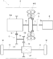
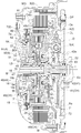
- FIG. 3 is a partially enlarged view of FIG. 2.
- the hybrid drive device 1 is a drive device for a hybrid vehicle that uses one or both of the internal combustion engine E and the rotating electrical machine MG as a drive force source of the vehicle.
- the hybrid drive device 1 is configured as a so-called 1-motor parallel type hybrid drive device.
- the hybrid drive device 1 includes an input shaft I that is drivingly connected to the internal combustion engine, a rotating electrical machine MG, an intermediate shaft M that is drivingly connected to the speed change mechanism TM, and an input shaft.
- a clutch CL that selectively drives and connects the I and the intermediate shaft M, and a case 2 that houses the clutch CL and the rotating electrical machine MG.
- the hybrid drive device 1 according to the present embodiment includes a clutch case CH that is supported in the radial direction with respect to the case 2 on both sides in the axial direction (see FIG. 2), and a pump drive shaft.
- the flow path L (see FIG.
- axial direction In the following description, unless otherwise specified, “axial direction”, “circumferential direction”, and “radial direction” are defined on the basis of the rotational axes of the input shaft I and the intermediate shaft M arranged on the same axis. Yes. These rotating shafts correspond to the rotating shafts of the rotating elements included in the clutch CL, the clutch case CH, the inner rotor 18b included in the oil pump 18, and the rotor Ro included in the rotating electrical machine MG.
- the left side in FIG. 2 is referred to as “one axial side” and the right side in FIG. 2 is referred to as “the other axial direction” unless otherwise specified.
- the hybrid drive device 1 includes an input shaft I that is drivingly connected to an internal combustion engine E as a first driving force source of a vehicle, and a rotating electrical machine MG as a second driving force source of the vehicle.
- the hybrid drive device 1 includes a clutch CL provided so as to be able to switch between transmission and disconnection of driving force between the input shaft I and the intermediate shaft M, a counter gear mechanism C, an output differential gear device DF, It has.
- a case 2 as a drive device case.
- the input shaft I and the intermediate shaft M correspond to the “first axis” and the “second axis” in the present invention, respectively.
- Drive coupling refers to a state where two rotating elements are coupled so as to be able to transmit a driving force, and the two rotating elements are coupled so as to rotate integrally, or the two rotating elements. Is used as a concept including a state in which a driving force can be transmitted through one or more transmission members. Examples of such a transmission member include various members that transmit rotation at the same speed or a variable speed, and include, for example, a shaft, a gear mechanism, a belt, a chain, and the like. Further, “driving force” is used synonymously with torque.
- the “rotary electric machine” is used as a concept including a motor (electric motor), a generator (generator), and a motor / generator that performs both functions of the motor and the generator as necessary.
- the internal combustion engine E is a device that is driven by combustion of fuel inside the engine to extract power, and for example, various known engines such as a gasoline engine and a diesel engine can be used.
- an internal combustion engine output shaft Eo such as a crankshaft of the internal combustion engine E is drivingly connected to the input shaft I via a damper D.
- the input shaft I is drivingly connected to the rotating electrical machine MG and the intermediate shaft M via the clutch CL, and the input shaft I is selectively connected to the rotating electrical machine MG and the intermediate shaft M by the clutch CL.
- the internal combustion engine E and the rotary electric machine MG are drivingly connected via the input shaft I, and in the released state of the clutch CL, the internal combustion engine E and the rotary electric machine MG are separated.
- the rotating electrical machine MG includes a stator St and a rotor Ro, and functions as a motor (electric motor) that generates power by receiving power supply, and a generator (power generation) that generates power by receiving power supply. Function). Therefore, rotating electrical machine MG is electrically connected to a power storage device (not shown). In this example, a battery is used as the power storage device. Note that it is also preferable to use a capacitor or the like as the power storage device.
- the rotating electrical machine MG is powered by receiving electric power from the battery, or supplies the battery with electric power generated by the torque output from the internal combustion engine E or the inertial force of the vehicle.
- the rotor Ro of the rotating electrical machine MG is drivingly connected so as to rotate integrally with the intermediate shaft M.
- the intermediate shaft M is an input shaft (transmission input shaft) of the speed change mechanism TM.
- the speed change mechanism TM is a device that changes the rotational speed of the intermediate shaft M at a predetermined speed ratio and transmits it to the speed change output gear G.
- the transmission mechanism TM includes a single pinion type and Ravigneaux type planetary gear mechanism and a plurality of engagement devices such as a clutch, a brake, and a one-way clutch.
- An automatic transmission mechanism provided with a switchable gear is used.
- As the speed change mechanism TM an automatic speed change mechanism having other specific configurations, an automatic continuously variable speed change mechanism capable of changing the speed ratio steplessly, and a plurality of speed stages having different speed ratios can be switched.
- a manual stepped transmission mechanism or the like may be used.
- the speed change mechanism TM changes the rotational speed of the intermediate shaft M at a predetermined speed change ratio at each time point, converts torque, and transmits the torque to the speed change output gear G.
- the counter gear mechanism C transmits the rotation and torque of the transmission output gear G to the wheel W side.
- the counter gear mechanism C has a counter shaft Cs, a first gear C1, and a second gear C2.
- the first gear C1 meshes with the transmission output gear G.
- the second gear C2 meshes with the differential input gear Di included in the output differential gear device DF.
- the differential gear device for output DF distributes the rotation and torque of the differential input gear Di to the plurality of wheels W and transmits them.
- the output differential gear device DF is a differential gear mechanism using a plurality of bevel gears meshing with each other, and is transmitted to the differential input gear Di via the second gear C2 of the counter gear mechanism C. Is distributed to the two left and right wheels W via the output shaft O, respectively.
- the hybrid drive device 1 transmits the torque of one or both of the internal combustion engine E and the rotating electrical machine MG to the wheels W to cause the vehicle to travel.
- the input shaft I and the intermediate shaft M are coaxially arranged, and the counter shaft Cs and the output shaft O are the input shaft I and the intermediate shaft M, respectively. They are arranged parallel to each other on different axes.
- Such a configuration is suitable as a configuration of the hybrid drive device 1 mounted on, for example, an FF (Front Engine Front Drive) vehicle.
- the case 2 includes a case peripheral wall 3 that covers the outer periphery of each housing component such as the rotating electrical machine MG and the speed change mechanism TM housed therein, and the other axial side of the case peripheral wall 3 (internal combustion engine).
- the first support wall 4 that closes the opening on the E side), and the rotating electrical machine MG and the speed change in the axial direction on one axial side of the first support wall 4 (on the side opposite to the internal combustion engine E, that is, the speed change mechanism TM side).
- a second support wall 7 disposed between the mechanism TM.
- the case 2 includes an end support wall (not shown) that closes one end of the case peripheral wall 3 in the axial direction.
- the first support wall 4 has a shape extending at least in the radial direction, and extends in the radial direction and the circumferential direction in the present embodiment.
- An axial through hole is formed in the first support wall 4, and an input shaft I inserted through the through hole is inserted into the case 2 through the first support wall 4.
- the first support wall 4 is integrally provided with a cylindrical (boss-shaped) axial projecting portion 5 projecting to one axial side.
- the first support wall 4 is located on one axial side so that the radially inner portion is positioned on one axial side with respect to the radially outer portion in the portion where the input shaft I is penetrated. It is set as the wall part which has the shape curved in the dish shape which becomes convex toward it.
- the first support wall 4 is disposed adjacent to a clutch case CH, which will be described later, at a predetermined interval on the other side in the axial direction. Further, an oil passage forming member 71 having a discharge oil passage 72 formed therein is attached to the first support wall 4 along the radial direction.
- the second support wall 7 has a shape extending at least in the radial direction, and in the present embodiment, extends in the radial direction and the circumferential direction.
- An axial through hole is formed in the second support wall 7.
- the second support wall 7 is integrally provided with an overall cylindrical (boss-like) cylindrical portion 7a extending in the axial direction at the radially inner end thereof, and the inner portion of the cylindrical portion 7a
- the peripheral surface defines the outer edge of the through hole formed in the second support wall 7.
- the cylindrical portion 7a functions as a resolver fixing portion for fixing the sensor stator of the resolver 19, and also causes the pump case 8 (the pump body 90 in this example) of the oil pump 18 in the radial direction. It also functions as a positioning part for positioning.
- the second support wall 7 is disposed adjacent to the clutch case CH at a predetermined interval on one side in the axial direction.
- the oil pump 18 is provided inside the second support wall 7 in the radial direction with respect to the radial direction.
- the oil pump 18 is provided between the speed change mechanism TM and the clutch case CH in the axial direction, in other words, between the speed change mechanism TM and the rotating electrical machine MG.
- the oil pump 18 is disposed coaxially with the input shaft I and the intermediate shaft M.
- the clutch case CH is also arranged coaxially with the input shaft I and the intermediate shaft M.
- the speed change mechanism TM is arranged on one side in the axial direction with respect to the clutch case CH. Therefore, it can be said that the oil pump 18 is disposed coaxially with the clutch case CH on one side in the axial direction with respect to the clutch case CH.
- the oil pump 18 is fixed to the case 2 and includes a pump case 8 that forms a pump chamber 18a therein, an inner rotor 18b that is rotatably disposed in the pump chamber 18a, and a rotatably disposed in the pump chamber 18a.
- the pump case 8 is formed by joining a pump body 90 disposed on the other side in the axial direction and a pump cover 91 disposed on the one side in the axial direction.
- An axial through hole is formed in the pump case 8 (specifically, both the pump body 90 and the pump cover 91), and the intermediate shaft M inserted through the through hole is connected to the pump case 8 ( It penetrates the oil pump 18).
- the inner rotor 18b corresponds to the “pump rotor” in the present invention.
- the pump body 90 is an annular plate-like member extending in the radial direction and the circumferential direction, and a cylindrical (boss-like) axial protruding portion 90b that protrudes on the other side in the axial direction is formed at the other end in the axial direction.
- the pump body 90 has a shape in which the other side in the axial direction bulges out in a cylindrical shape as a whole, and has a shape protruding toward the clutch case CH and the rotating electrical machine MG in the axial direction.
- a recess for forming the pump chamber 18a is formed in a circular cross section when viewed from the axial direction on one end face in the axial direction of the pump body 90.
- the pump body 90 is positioned in the radial direction by fitting the outer peripheral surface of the pump body 90 to the inner peripheral surface of the cylindrical portion 7 a of the second support wall 7. Specifically, the pump body 90 is disposed so that the outer peripheral surface of the pump body 90 and the inner peripheral surface of the cylindrical portion 7a face each other, and the outer peripheral surface of the pump body 90 and the inner peripheral surface of the cylindrical portion 7a.
- a fourth seal member 64 is interposed therebetween.
- the fourth seal member 64 is an O-ring, and is attached to a concave groove formed in the outer peripheral surface of the pump body 90 and extending in the circumferential direction.
- the space between the outer peripheral surface of the pump body 90 and the inner peripheral surface of the cylindrical portion 7a of the second support wall 7 is oil-tight (liquid-tight). It will be sealed. That is, the pump body 90 is oil-tightly fitted to the cylindrical portion 7 a via the fourth seal member 64 and is positioned and held on the second support wall 7.
- the pump cover 91 is an annular plate member extending in the radial direction and the circumferential direction. And the axial direction one side end surface of the pump body 90 and the axial direction other side end surface of the pump cover 91 are joined, so that the inner rotor 18b and the outer rotor 18c are accommodated inside the pump body 90 and the pump cover 91.
- a pump chamber 18a is formed. Specifically, the pump chamber 18 a is formed by the concave portion having the circular cross section provided in the pump body 90 and the other end surface in the axial direction of the pump cover 91.
- the pump body 90 and the pump cover 91 are fastened and fixed to each other by a fastening bolt (not shown). Further, the pump case 91 is fixed to the case 2 by the pump cover 91 being fastened and fixed to the case 2 by the fastening bolts 81.
- the oil pump 18 is an inscribed gear pump having an inner rotor 18b and an outer rotor 18c.
- the inner rotor 18b and the outer rotor 18c are accommodated in the pump chamber 18a so as to be rotatable in an eccentric manner.
- the inner rotor 18b is a pump gear arranged coaxially with the intermediate shaft M, and is drivingly connected so as to rotate integrally with a pump drive shaft 10 to be described later at a central portion in the radial direction.
- the inner rotor 18b and the pump drive shaft 10 are drivingly connected.
- the inner rotor 18b and the pump drive shaft 10 may be spline-connected.
- the pump drive shaft 10 is provided integrally with a member (one-side radial extending portion 45) constituting the clutch case CH, and rotates integrally with the clutch case CH.
- the oil pump 18 draws oil from the suction chamber 92 into the pump chamber 18a to generate hydraulic pressure, and discharges the oil into a discharge chamber (not shown).
- the oil discharged into the discharge chamber is supplied to the clutch CL, the speed change mechanism TM, and the like. That is, the oil pump 18 generates hydraulic pressure for operating the clutch CL and the speed change mechanism TM.
- oil passages are formed in the pump case 8 (pump body 90, pump cover 91), the intermediate shaft M, and the like, respectively, and the oil discharged by the oil pump 18 is supplied to a hydraulic control device (not shown) and It distributes through these oil passages and is supplied to each part to be supplied with oil.
- the second support wall 7 extending in the radial direction and the circumferential direction, and the pump case 8 (the pump body 90, the pump cover extending in the radial direction and the circumferential direction) are also provided. 91), the space in the case 2 is partitioned in the axial direction. That is, the second support wall 7 and the pump case 8 cooperate to form a wall portion extending in the radial direction and the circumferential direction, and the space in the case 2 is partitioned in the axial direction by the wall portion.
- the transmission mechanism TM is accommodated in the second chamber.
- the first chamber Oil is basically prohibited from passing through the oil passage between the first chamber and the second chamber.
- the pump case 8 (pump body 90) supports the clutch case CH via the first bearing 51.
- the first bearing 51 is supplied with oil leaking from the pump chamber 18a to the other side in the axial direction through the space between the pump body 90 and the pump drive shaft 10.
- the pump body 90 and the pump cover 91 are formed with a discharge oil passage 9 for discharging the oil that has lubricated the first bearing 51.
- the amount of oil discharged from the oil pump 18 through a discharge chamber decreases according to the amount of oil leaking from the pump chamber 18a to the other side in the axial direction, oil leakage from the pump chamber 18a. It is desirable that the amount be limited to an amount that can adequately lubricate the first bearing 51.
- the input shaft I is a shaft for inputting the torque of the internal combustion engine E to the hybrid drive device 1, and is drivingly connected to the internal combustion engine E at the other end portion in the axial direction.
- the input shaft I is disposed in a state of penetrating the first support wall 4, and as shown in FIG. 2, the internal combustion engine E is interposed via a damper D on the other axial side of the first support wall 4.
- the internal combustion engine output shaft Eo is driven and connected to rotate integrally.
- the damper D is a device that transmits the rotation of the internal combustion engine output shaft Eo to the input shaft I while attenuating torsional vibration of the internal combustion engine output shaft Eo, and various known devices can be used.
- the damper D has a plurality of coil springs arranged along the circumferential direction, and is fixed and integrated with a drive plate DP fixed to the internal combustion engine output shaft Eo.
- the input shaft I is splined.
- the damper D as a whole has a smaller diameter than the drive plate DP, and is disposed on one axial side of the drive plate DP.
- a third seal is formed across the input shaft I and the first support wall 4 to prevent leakage of oil to the other side in the axial direction (damper D and internal combustion engine E side) between them.
- a member 63 is provided.
- a shaft end hole portion 12 extending in the axial direction is formed in the inner diameter portion of one end portion in the axial direction of the input shaft I.
- the other end portion in the axial direction of the intermediate shaft M enters the shaft end hole portion 12 in the axial direction.
- the input shaft I is integrally provided with a flange portion 11 extending radially from the main body portion (portion extending in the axial direction) of the input shaft I at one end portion in the axial direction thereof.
- the flange portion 11 enters the clutch case CH and is connected to the clutch hub 21 of the clutch CL accommodated in the clutch case CH.
- a fourth bearing 54 is disposed on the other axial side of the flange 11, and a third bearing is provided on the outer side in the radial direction of the flange 11 and on the one axial side of the clutch hub 21 of the clutch CL.
- a bearing 53 is provided.
- the intermediate shaft M is a shaft for inputting one or both of the torque of the rotating electrical machine MG and the torque of the internal combustion engine E via the clutch CL to the transmission mechanism TM, and is splined to the clutch case CH. As shown in FIG. 2, the intermediate shaft M is disposed so as to penetrate the oil pump 18. As described above, an axial through hole is formed in the central portion of the pump case 8 in the radial direction, and the intermediate shaft M passes through the oil pump 18 through the through hole.
- the intermediate shaft M is supported in the radial direction so as to be rotatable with respect to the oil pump 18.
- the pump case 8 of the oil pump 18 rotatably supports the intermediate shaft M that is an input shaft (transmission input shaft) of the transmission mechanism TM.
- the intermediate shaft M has a plurality of oil passages including a supply oil passage 15 and a discharge oil passage 16 on the inner diameter portion thereof.
- the supply oil passage 15 extends in the axial direction on the other axial side of the intermediate shaft M and extends in the radial direction at a predetermined position in the axial direction so as to communicate with the hydraulic oil chamber 37 of the clutch CL. Is open.
- the discharge oil passage 16 extends in the axial direction at a position different from the supply oil passage 15 in the axial direction on the other side in the axial direction of the intermediate shaft M, and opens to the end surface on the other side in the axial direction.
- the clutch CL is provided so as to be able to switch between transmission and disconnection of the driving force between the input shaft I and the intermediate shaft M, and selectively engages and connects the internal combustion engine E and the rotating electrical machine MG. It is.
- the clutch CL is configured as a wet multi-plate clutch mechanism that operates in a space to which oil is supplied. As shown in FIG. 2, the clutch CL includes a clutch hub 21 that is an input side member, a clutch drum 26 that is an output side member, a plurality of friction plates 31, and a piston 36.
- the clutch hub 21 is formed in a cylindrical shape and holds a plurality of friction plates 31 from the radially inner side, and an annular plate shape extending radially inward from the other axial end of the cylindrical portion 22. Part 24.
- the clutch hub 21 is connected to the flange portion 11 of the input shaft I so as to rotate integrally with the input shaft I, and is disposed radially inward with respect to the clutch drum 26.
- the input shaft I is drivingly connected to the internal combustion engine E. Therefore, the clutch hub 21 is drivingly connected to the internal combustion engine E via the input shaft I.
- the clutch drum 26 is formed in a cylindrical shape and holds a plurality of friction plates 31 from the outside in the radial direction.
- the clutch drum 26 is connected so as to rotate integrally with the intermediate shaft M via the clutch case CH.
- the intermediate shaft M is drivingly connected to the speed change mechanism TM. Therefore, the clutch drum 26 is drivingly connected to the speed change mechanism TM via the clutch case CH and the intermediate shaft M.
- the intermediate shaft M drives and connects the clutch drum 26 and the speed change mechanism TM.
- a plurality of friction plates 31 are slidably held in the axial direction on the clutch hub 21 and the clutch drum 26.
- a backing plate 32 that functions as a pressing member when the friction plates 31 are engaged with each other is held on the other axial side of the plurality of friction plates 31.
- the backing plate 32 is held in a state where movement in the axial direction is restricted by the snap ring 33.
- the piston 36 is arranged on one axial side with respect to the plurality of friction plates 31 in a state where it is urged to one axial side by a return spring.
- a fluid-tight hydraulic oil chamber 37 is formed between the clutch case CH integrated with the clutch drum 26 and the piston 36.
- the hydraulic oil chamber 37 is an oil chamber for controlling the engagement state (complete engagement, complete release, or partial engagement therebetween) of the clutch CL.
- pressure oil discharged by the oil pump 18 and adjusted to a predetermined hydraulic pressure by a hydraulic control device is formed in the supply oil passage 15 formed in the intermediate shaft M and the clutch case CH. Supplied through the connecting oil passage 48.
- the hydraulic pressure in the hydraulic oil chamber 37 increases and becomes larger than the urging force of the return spring, the piston 36 moves in the direction of expanding the volume of the hydraulic oil chamber 37 (in this example, the other side in the axial direction), and the backing plate 32.
- a circulating oil chamber 38 is formed on the opposite side of the piston 36 from the hydraulic oil chamber 37.
- the circulating oil chamber 38 is an oil chamber in which oil for mainly cooling the clutch CL circulates.
- the pressure oil discharged by the oil pump 18 and adjusted to a predetermined hydraulic pressure by a hydraulic control device is continuously supplied to both the clutch case CH and the pump drive shaft 10 in the axial direction. It is supplied through the formed circulating oil passage 47. That is, the pump drive shaft 10 includes a circulating oil passage 47 that is an oil passage for supplying oil to the clutch CL.
- the circulating oil passage 47 corresponds to the “supply oil passage” in the present invention.
- the clutch case CH is a case that accommodates the clutch CL, and includes a pump drive shaft 10 that extends to one side in the axial direction and is drivingly connected to the inner rotor 18b.
- the clutch case CH is disposed across the input shaft I and the intermediate shaft M in a state of rotating relative to the input shaft I and rotating integrally with the intermediate shaft M. That is, in the present embodiment, the clutch case CH is drivingly connected to the intermediate shaft M of the input shaft I and the intermediate shaft M.
- the clutch case CH surrounds both the axial direction both sides and the radially outer side of the clutch CL on the radially outer side of the input shaft I and the intermediate shaft M arranged on the same axis and accommodates the clutch CL.
- the clutch case CH is disposed on the other side in the axial direction of the clutch CL and extends in the radial direction on the other side, and the one side diameter is disposed on the one side in the axial direction of the clutch CL and extends in the radial direction.
- a direction extending portion 45 and a cylindrical axial extending portion 49 that is disposed on the radially outer side of the clutch CL and extends in the axial direction are configured.
- the axially extending portion 49 connects the one side radially extending portion 45 and the other side radially extending portion 41 in the axial direction at these radially outer ends.
- the other-side radial extending portion 41 has a shape extending at least in the radial direction, and extends in the radial direction and the circumferential direction in the present embodiment.
- the other-side radial extending portion 41 defines the other axial side of the circulating oil chamber 38.
- An axial through hole is formed in the radial center of the other side radially extending portion 41, and the input shaft I inserted through this through hole penetrates the other side radially extending portion 41 to clutch. It is inserted in the case CH.
- the other-side radial extending portion 41 is integrally provided with a cylindrical (boss-shaped) axial projecting portion 42 projecting toward the other axial end at the radially inner end thereof.
- the axial protrusion 42 is formed so as to surround the input shaft I.
- a fifth bearing 55 is disposed between the axial protrusion 42 and the input shaft I.
- the portion excluding the axial protrusion 42 in the other-side radial extending portion 41 is a main body portion, in this example, the main body portion of the other-side radial extending portion 41 has a radially inner portion as a whole in the radial direction.
- the member has a dish-like shape that is convex toward one side in the axial direction so as to be positioned on one side in the axial direction with respect to the outer portion.
- the other-side radial extending portion 41 is adjacent to the first support wall 4 at a predetermined interval on one side in the axial direction, and the axial protrusion 42 is connected to the axial protrusion 5 of the first support wall 4. On the other hand, they are arranged in a state adjacent to each other at a predetermined interval on the radially inner side. Further, the other-side radial extending portion 41 is disposed adjacent to the clutch hub 21 and the flange portion 11 of the input shaft I at a predetermined interval on the other side in the axial direction.
- the 2nd bearing 52 and the space between these are made into a liquid-tight state to the axial direction one side (rotary electrical machine MG side).
- a second seal member 62 for suppressing oil leakage is disposed. That is, the second bearing 52 supports the other-side radial extending portion 41 constituting the clutch case CH so as to be rotatable relative to the case 2 that is a non-rotating member. As shown in FIG. 2, the second bearing 52 is disposed in a state of coming into contact with a stepped portion 42 a (a portion where the outer diameter changes) formed on the outer peripheral surface of the axial protruding portion 42 from the other side in the axial direction. Yes.
- the second bearing 52 is a bearing (rolling bearing) including an outer ring, an inner ring, and rolling elements interposed between the outer ring and the inner ring.
- the second bearing 52 is a ball bearing whose rolling element is a ball, and is configured to receive both a radial load and an axial load. That is, the hybrid drive device 1 according to the present embodiment includes the second bearing 52 that supports the clutch case CH in the radial direction and the axial direction with respect to the case 2 on the other axial side. As shown in FIG. 2, the second bearing 52 overlaps the other side radial extending portion 41 (specifically, the radially outer portion of the other side radial extending portion 41) in the axial direction. Has been placed.
- the second bearing 52 is disposed so as to overlap with the other-side radially extending portion 41 (specifically, the radially outer portion of the other-side radially extending portion 41) when viewed from the radial direction. .
- the second bearing 52 only needs to support at least the clutch case CH in the radial direction on the other side in the axial direction, and may be a bearing other than the ball bearing.
- the second bearing 52 can be a roller bearing using a rolling element as a roller.
- overlap in a certain direction means that at least part of the two members has the same position with respect to the arrangement in the direction.
- the axially extending portion 49 has a cylindrical shape that surrounds the radially outer side of the clutch CL.
- the axially extending portion 49 extends from the radially outer end of the other radial extending portion 41 toward the one axial side. It is extended.
- the axially extending portion 49 defines the radially outer side of the circulating oil chamber 38.
- the axially extending portion 49 is formed integrally with the other side radially extending portion 41.
- the axially extending portion 49 is disposed on the outer side in the radial direction of the clutch drum 26 with a predetermined gap between the axially extending portion 49 and the clutch drum 26. That is, the axially extending portion 49 is disposed so that the inner peripheral surface of the axially extending portion 49 and the outer peripheral surface of the clutch drum 26 are opposed to each other with a predetermined interval in the radial direction.
- the axially extending portion 49 is formed in a stepped shape that gradually goes outward in the radial direction as it goes toward one side in the axial direction. And the outer peripheral surface of the part located in the axial direction other side in the axial direction extension part 49 is made into the 1st contact part 49a which contacts and supports the internal peripheral surface of rotor Ro of the rotary electric machine MG from radial inside. Yes. That is, in this example, the rotor Ro of the rotating electrical machine MG is supported by the clutch case CH.
- the second contact where the inner peripheral surface of the axially extending portion 49 located on one side in the axial direction with respect to the first contact portion 49 a contacts the outer peripheral surface of the one-side radial extending portion 45.
- a portion 49b is provided.
- the second contact portion 49b is located on the radially outer side with respect to the first contact portion 49a.
- the one-side radial extending portion 45 has a shape extending at least in the radial direction, and extends in the radial direction and the circumferential direction in the present embodiment.
- the one side radially extending portion 45 is a radially inner portion of the piston 36 and a radially outer portion of the hydraulic oil chamber 37 and defines one axial side of the circulating oil chamber 38.
- An axial through hole is formed in the radial center of the one side radially extending portion 45, and the intermediate shaft M inserted through the through hole penetrates the one side radially extending portion 45 to engage the clutch. It is inserted in the case CH.
- the one-side radial extending portion 45 is integrally provided with a cylindrical (boss-shaped) axial projecting portion 46 projecting to one axial side at the radially inner end thereof.
- the axial protruding portion 46 is formed so as to surround the periphery of the intermediate shaft M.
- the radially extending portion 45 (axially projecting portion 46) is in contact with the outer peripheral surface of the intermediate shaft M over the entire circumferential direction at the radially inner end.
- a portion excluding the axial protrusion 46 in the one-side radial extending portion 45 is a main body portion
- the main body portion of the one-side radial extending portion 45 has a radially inner portion as a whole in the radial direction.
- the radially inner portion is a plate-like member having a shape offset to the other axial side with respect to the radially outer portion so as to be positioned on the other axial side with respect to the outer portion.
- the pump drive shaft 10 that extends to one side in the axial direction and is drivingly connected to the inner rotor 18b is provided at the radially inner end of the one side radially extending portion 45.
- the pump drive shaft 10 is formed integrally with the one-side radial extending portion 45, specifically, the other end portion in the axial direction of the pump drive shaft 10.
- one axial end of the axial protrusion 46 are integrally connected.
- the pump drive shaft 10 is splined to rotate integrally with the intermediate shaft M.
- the outer diameter of the axial protrusion 46 is larger than the outer diameter of the pump drive shaft 10.
- an annular surface formed by one axial end surface of the axial projection 46 and an outer peripheral surface of the pump drive shaft 10 are formed at the connecting portion that is a boundary between the axial projection 46 and the pump drive shaft 10. are formed in a positional relationship orthogonal to each other, and the first bearing 51 described later can be appropriately fixed.
- the one side radial extending portion 45 is adjacent to the second support wall 7 and the oil pump 18 (pump body 90) on the other side in the axial direction with a predetermined interval, and the axial protrusion 46 and the pump drive shaft. 10 is arranged in a state of being adjacent to the axial projecting portion 90b included in the pump body 90 at a predetermined interval radially inward. Further, the one-side radial extending portion 45 is disposed adjacent to the clutch hub 21 and the flange portion 11 of the input shaft I at a predetermined interval on one side in the axial direction at the radially inner portion. .
- the 1st bearing 51 is arrange
- a first seal member 61 is disposed to prevent the oil from leaking to the other side in the axial direction (rotating electrical machine MG side). That is, the pump drive shaft 10 is supported by the pump body 90 (pump case 8) via the first bearing 51. As described above, the pump case 8 is fixed to the case 2. Therefore, the pump drive shaft 10 is supported by the case 2 via the first bearing 51 and the pump case 8. As shown in FIG. 2, the first bearing 51 is disposed in a state in which the first bearing 51 is in contact with the end surface on one side in the axial direction of the axial protrusion 46 from the one side in the axial direction.
- the pump drive shaft 10 is formed integrally with the one-side radial extending portion 45 constituting the clutch case CH, the one-side radial extending portion 45 is the first bearing.
- the pump body 90 (pump case 8) is supported via 51. That is, the first bearing 51 can rotate the one side radial direction extending portion 45 constituting the clutch case CH relative to the pump case 8 which is a non-rotating member and the case 2 to which the pump case 8 is fixed. I support it.
- the first bearing 51 is a bearing (rolling bearing) including an outer ring 51a, an inner ring 51b, and rolling elements 51c interposed between the outer ring 51a and the inner ring 51b (see FIG. 3). ).
- the first bearing 51 is a ball bearing whose rolling elements are balls, and is configured to receive both a radial load and an axial load. That is, the hybrid drive device 1 according to the present embodiment includes the first bearing 51 that supports the clutch case CH in the radial direction and the axial direction with respect to the case 2 on one side in the axial direction.
- the clutch case CH is supported by the first bearing 51 and the second bearing 52 in the radial direction and the axial direction with respect to the case 2 on both sides in the axial direction. And both the 1st bearing 51 and the 2nd bearing 52 are made into the rolling bearing (this example ball bearing) provided with the outer ring
- the clutch case CH can be accurately supported in the radial direction, and the radial displacement of the outer peripheral surface of the pump drive shaft 10 provided in the clutch case CH is suppressed within a relatively narrow range. Is an easy configuration.
- the outer ring 51a of the first bearing 51 is fitted to the inner peripheral surface of the axial projecting portion 90b (in this example, an interference fit by press-fitting) and is positioned and fixed in the radial direction.
- the inner ring 51b It is fitted to the outer peripheral surface of the drive shaft 10 (in this example, it is an interference fit with a small interference or a clearance fit compared to the fitting of the outer ring 51a) and is positioned and fixed in the radial direction.
- the first bearing 51 overlaps in the axial direction with the one side radially extending portion 45 (specifically, the radially outer portion of the one side radially extending portion 45). Has been placed.
- the first bearing 51 is disposed so as to overlap with the one side radial extending portion 45 (specifically, the radially outer portion of the one side radial extending portion 45) when viewed from the radial direction.
- the first bearing 51 may be any bearing that can support at least the clutch case CH in the radial direction on one axial side, and may be a rolling bearing other than a ball bearing.
- the first bearing 51 can be a roller bearing using a rolling element as a roller.
- the one side radially extending portion 45 is connected to a portion on the one axial side of the axial extending portion 49 in the vicinity of the radially outer end portion.
- the one-side radial extending portion 45 is fitted to the second contact portion 49 b of the axial extending portion 49 (in this example, an interference fit by press fitting). In this state, they are joined by welding. That is, the one-side radial extending portion 45 and the axial extending portion 49 are joined and integrated by welding. In addition, welding is performed from one axial direction side with respect to the contact portion between the inner peripheral surface (second contact portion 49b) of the axially extending portion 49 and the outer peripheral surface of the one-side radial extending portion 45.
- the welded joint portion 85 is formed around the same radial position as the second contact portion 49b.
- the second contact portion 49b is positioned on the radially outer side with respect to the first contact portion 49a that contacts and supports the inner peripheral surface of the rotor Ro from the radially inner side. Therefore, the joining portion 85 is located on the radially outer side than the inner peripheral surface of the rotor Ro.
- the joint part 85 by welding can be made into the position away from the pump drive shaft 10 in the radial direction, and the pump drive shaft 10 and the pump drive shaft 10 are provided at the radially inner end by heat during welding. It is suppressed that the formed one side radial direction extension part 45 deform
- the radially outer portion of the one-side radially extending portion 45 and the axially one-side portion of the axially extending portion 49 face each other in the radial direction. And the surfaces facing each other in the axial direction are joined by welding in a state where both surfaces are in contact with each other. Thereby, it is suppressed that the heat at the time of welding is concentrated and transmitted only to any one member of the one side radial direction extension part 45 and the axial direction extension part 49, and the one side diameter direction It is suppressed that the temperature of the extension part 45 and the axial direction extension part 49 becomes excessive, and deform
- the clutch drum 26 is integrally formed with the one side radially extending portion 45. More specifically, a cylindrical clutch drum extends in the vicinity of the radially outer end portion of the one side radial extension portion 45 from the one side radial extension portion 45 toward the other side in the axial direction. 26 is integrally formed.
- a hydraulic oil chamber 37 is formed between the radially inner portion of the one-side radially extending portion 45 and the piston 36.
- the one-side radial extending portion 45 as a whole is radially inclined while being slightly inclined toward the other side in the axial direction with respect to the radial direction so as to communicate the supply oil passage 15 and the hydraulic oil chamber 37.
- a communication oil passage 48 is formed in the axial protrusion 46.
- the space that occupies most of the space excluding the hydraulic oil chamber 37 is the circulating oil chamber 38 described above.
- the oil that is discharged by the oil pump 18 and adjusted to a predetermined hydraulic pressure is a circulating oil passage 47 formed so as to extend in the axial direction in the pump drive shaft 10 and the axial protrusion 46.
- the fifth bearing 55 disposed between the axial projecting portion 42 formed on the other radial extension portion 41 and the input shaft I can ensure a certain degree of liquid tightness.
- the bearing with a sealing function is configured (here, a needle bearing with a seal ring).
- the inner peripheral surface of the one-side radial extending portion 45 (axial protruding portion 46) is in contact with the outer peripheral surface of the intermediate shaft M over the entire circumferential direction at the radially inner end portion. Therefore, when oil is supplied to the circulating oil chamber 38 via the circulating oil passage 47, the circulating oil chamber 38 in the clutch case CH is basically always filled with oil.
- the oil basically circulates in the circulating oil chamber 38 while maintaining a state always filled with oil. This flow is indicated by broken-line arrows in FIG. That is, the oil supplied to the circulating oil chamber 38 from the circulating oil passage 47 first passes between the one-side radial extending portion 45 and the flange portion 11 and between the piston 36 and the clutch hub 21 in the radial direction. It flows toward the outside and cools the plurality of friction plates 31. Then, the oil that has cooled the plurality of friction plates 31 flows between the clutch hub 21 and the flange portion 11 and the other side radially extending portion 41 toward the radially inner side, and the base of the flange portion 11 Reach the end.
- the oil is discharged from the circulating oil chamber 38.
- the plurality of friction plates 31 provided in the clutch CL can be effectively cooled with a large amount of oil that is always filled in the circulating oil chamber 38. .
- the cylindrical portion 22 of the clutch hub 21 has a diameter in order to efficiently introduce oil supplied from the radially inner side into the gap between the friction plates 31.
- a through hole 23 (a slit-like through hole in this example) penetrating in the direction is formed.
- the clutch drum 26 is formed with a through hole 27 (a slit-like through hole in this example) that penetrates in the radial direction. Yes.
- the oil supplied from the radially inner side is efficiently introduced into the gap between the friction plates 31, and the cooling efficiency of the plurality of friction plates 31 can be improved.
- the oil may flow in the circumferential direction at the same time, but the main flow of the oil is as described above.
- the oil discharge path from the circulating oil chamber 38 is divided into two systems.
- the first discharge path is through a radial communication hole opened on the outer peripheral surface of the input shaft I and a discharge oil path 16 formed in the inner diameter portion of the intermediate shaft M.
- the outer diameter of the other end portion in the axial direction of the intermediate shaft M is formed to be slightly smaller than the inner diameter of the shaft end hole portion 12 of the input shaft I.
- a predetermined gap is formed between the other end surface and the surface defining the axial bottom of the shaft end hole 12 of the input shaft I.
- the second discharge path is intended for oil leaking in the axial direction from the fifth bearing 55, and passes through the discharge oil path 72 inside the oil path forming member 71 attached to the first support wall 4.
- Such a second discharge path includes the third seal member 63 disposed between the input shaft I and the first support wall 4, and the axial protrusion 42 of the clutch case CH and the first support wall 4. It is defined by a second seal member 62 disposed between the axial projection 5.
- the rotating electrical machine MG is arranged coaxially with the intermediate shaft M on the radially outer side of the clutch case CH.
- the rotating electrical machine MG includes a stator St fixed to the case 2 and a rotor Ro that is rotatably supported on the radially inner side of the stator St. That is, the rotating electrical machine includes the rotor Ro on the radially inner side with respect to the stator St.
- the stator St includes a stator core that is configured as a laminated structure in which a plurality of annular plate-shaped electromagnetic steel plates are stacked and is fixed to the first support wall 4, and a coil that is wound around the stator core.
- the rotor Ro of the rotating electrical machine MG includes a rotor core configured as a laminated structure in which a plurality of annular plate-shaped electromagnetic steel plates are stacked, and a permanent magnet embedded in the rotor core.
- the rotating electrical machine MG is disposed coaxially with the clutch case CH so as to overlap the clutch case CH in the axial direction. That is, the rotating electrical machine MG is disposed so as to overlap with the clutch case CH when viewed from the radial direction.
- the rotor Ro of the rotating electrical machine MG is fixed to the outer peripheral portion of the axially extending portion 49 constituting the clutch case CH.
- the rotor Ro of the rotating electrical machine MG is fixed to the first contact portion 49 a included in the axially extending portion 49.
- the clutch case CH also functions as a rotor support member that supports the rotor Ro, and in this embodiment, the clutch case CH and the rotor support member are formed in common.
- the clutch case CH is supported by the first bearing 51 and the second bearing 52 in the radial direction and the axial direction with respect to the case 2 on both sides in the axial direction.
- both the first bearing 51 and the second bearing 52 are rolling bearings (in this example, ball bearings) each including an outer ring, an inner ring, and rolling elements.
- rolling bearings in this example, ball bearings
- the clutch drum 26 is thus integrally formed on the clutch case CH that rotates integrally with the rotor Ro of the rotating electrical machine MG. That is, the rotating electrical machine MG is drivingly connected to the clutch drum 26 that is an output side member of the clutch CL via the clutch case CH.
- the damper D is disposed with a predetermined gap on the other axial side of the first support wall 4.
- the damper D is in a space in which the first support wall 4 formed to have a dish-like shape that is convex toward one side in the axial direction is retracted to one side in the axial direction when viewed from the other side in the axial direction.
- the damper D is further arranged in the radial direction inside of the coil end portion Ce on the other axial side (internal combustion engine E side) of the stator St of the rotating electrical machine MG, overlapping with the coil end portion Ce in the axial direction.
- the damper D is disposed so as to overlap with the coil end portion Ce as viewed from the radial direction.
- a resolver 19 (an example of a rotation sensor) that is a sensor for detecting the rotation angle (rotation phase) of the rotor Ro relative to the stator St of the rotating electrical machine MG is disposed in the case 2.
- the resolver 19 is adjacent to both the second support wall 7 and the one-side radial extending portion 45 of the case 2 on one axial side of the clutch case CH. Has been placed.
- the resolver 19 is an outer rotor type resolver provided with a sensor stator radially inward with respect to the sensor rotor.
- the sensor stator of the resolver 19 is fixed to the cylindrical part 7a with which the 2nd support wall 7 is provided, and the sensor rotor of the resolver 19 is fixed to the internal peripheral surface of the axial direction one side edge part of the axial direction extension part 49. Yes.
- the first bearing 51 that supports the clutch case CH in the radial direction (in this example, the radial direction and the axial direction) on one side in the axial direction includes the pump chamber 18a. Oil leaked to the other side in the axial direction passes between the pump body 90 and the pump drive shaft 10, but in the present invention, a dedicated member (such as a seal member) for limiting oil leakage is disposed. Without this, it is possible to limit the amount of oil leaking from the pump chamber 18a to the other axial side.
- the oil leakage suppression structure from the pump chamber 18a according to the present embodiment will be described in detail with reference to FIG.
- the pump case 8 (in this example, the pump body 90) includes a partition wall 90a that partitions the first bearing 51 and the inner rotor 18b. That is, the pump chamber 18a is partitioned on the other side in the axial direction by the partition wall 90a. Further, one axial side of the pump chamber 18a is partitioned by a partition wall 91a provided in the pump case 8 (in this example, the pump cover 91). The partition wall 91a is disposed on the side opposite to the partition wall 90a in the axial direction with respect to the inner rotor 18b.
- the partition wall 90a includes a drive shaft insertion hole 90c through which the pump drive shaft 10 is inserted.
- the diameter (diameter) of the inner peripheral surface of the drive shaft insertion hole 90c is “ ⁇ c”.
- a gap between the outer peripheral surface of the pump drive shaft 10 and the inner peripheral surface of the drive shaft insertion hole 90 c is an oil flow passage L that flows from the pump chamber 18 a to the first bearing 51. That is, the flow path L is a flow path for oil that leaks from the pump chamber 18 a to the other axial side along the outer peripheral surface of the pump drive shaft 10.
- the pump drive shaft 10 has one axial side to reduce the drag distance when the first bearing 51 is assembled to the pump drive shaft 10 from one axial direction.
- the small diameter part 10a and the other axial side are formed in the step shape which becomes the large diameter part 10b.
- the diameter (diameter) of the outer peripheral surface of the small diameter portion 10a is “ ⁇ a”
- the diameter (diameter) of the outer peripheral surface of the large diameter portion 10b is “ ⁇ b”.
- a key groove 10d that engages with a key 18d provided in the inner rotor 18b is formed at one end in the axial direction of the small diameter portion 10a.
- the pump drive shaft 10 is arrange
- the 1st bearing 51 is arrange
- the axial widths of the inner rotor 18b and the outer rotor 18c are set slightly smaller than the axial width of the pump chamber 18a so that the inner rotor 18b and the outer rotor 18c can be rotated in the pump chamber 18a. Therefore, as shown in FIG. 3, there is a gap between the inner rotor 18b and the outer rotor 18c and the walls (partition wall 90a and partition wall 91a) that partition the pump chamber 18a. Therefore, not all of the oil whose pressure has been increased in the pump chamber 18a is discharged through the discharge chamber (not shown), but a part of the oil passes through this gap and becomes a lower pressure portion in the pump chamber 18a. Will flow. That is, the gap in the pump forms an oil passage in the pump chamber 18a.
- the pump internal flow path formed by the gap between the partition wall 90a and the inner rotor 18b is referred to as a first pump internal flow path L1.
- a flow path in the pump formed by a gap between the partition wall 91a and the inner rotor 18b is referred to as a second flow path L2 in the pump.
- the first pump internal flow path L ⁇ b> 1 has an axial width of “ ⁇ ” and communicates with the flow path L at the radially inner end thereof.
- the first pump internal flow path L1 also communicates with a space (hereinafter referred to as “target space”) formed radially inward with respect to the inner peripheral surface of the inner rotor 18b.
- the first pump internal flow path L1 located near the discharge port (discharge chamber) (not shown), as shown in FIG. 3, the first pump internal flow path L1.
- the flow path of the oil toward the flow path L through the target space is formed.
- the first pump internal flow path L1 corresponds to the “pump internal flow path” in the present invention.
- the second pump flow path L2 communicates with a space (a space indicated by a symbol L3 in FIG. 3) formed on one axial side of the pump drive shaft 10.
- This space is formed in an annular shape and communicates with the circulation oil passage 47 as shown in FIG. That is, this space is a communication path L3 that communicates the second pump internal flow path L2 and the circulating oil path 47.
- the second pump internal flow path L2 communicates with the circulating oil path 47 via the communication path L3.
- the communication path L3 is a low-pressure space with respect to the second pump internal flow path L2 located near a discharge port (discharge chamber) (not shown), and therefore, as shown in FIG.
- the circulating oil passage 47 is basically supplied with pressure oil discharged by the oil pump 18 and adjusted to a predetermined oil pressure by a hydraulic control device (not shown), but leaked from the pump chamber 18a. The oil is also supplied together.
- the second pump internal flow path L2 corresponds to the “partition wall side pump internal flow path” in the present invention.
- the axial widths of the first pump internal flow path L1 and the second pump internal flow path L2 change according to the axial position of the inner rotor 18b in the pump chamber 18a.
- the inner rotor 18b may be positioned outside the axial direction with respect to the axial center position of the pump chamber 18a, but in a steady state, Located near the axial center position. Therefore, the axial width of the second pump internal flow path L2 is the same as or close to the axial width ⁇ of the first pump internal flow path L1.
- the flow path diameter difference is set.
- the small diameter portion 10a of the pump drive shaft 10 faces the inner peripheral surface of the drive shaft insertion hole 90c
- the outer peripheral surface of the pump drive shaft 10 in the flow path L is the outer periphery of the small diameter portion 10a. It becomes a surface. Therefore, in this example, the flow path diameter difference is “ ⁇ c ⁇ a”.
- the difference between the diameter of the large-diameter portion 10b and the diameter of the small-diameter portion 10a of the pump drive shaft 10 is set as a pump shaft step width, and the flow passage diameter difference is set to a value smaller than the pump shaft step width.
- the flow passage diameter difference can be set to a value that is 1/2 or 1/4 of the pump shaft step width. Since the pump shaft step width is expressed as “ ⁇ b ⁇ a”, “ ⁇ c ⁇ a” (flow path diameter difference) is smaller than “ ⁇ b ⁇ a” (pump shaft step width). That is, the flow path diameter difference is set so that the relationship “ ⁇ b> ⁇ c> ⁇ a” is satisfied.
- the flow path diameter difference is set so that the flow path cross-sectional area of the flow path L is smaller than the flow path cross-sectional area of the first pump internal flow path L1.
- the flow path cross-sectional area of the flow path L can be set to a value that is 1/2 or 1/4 of the flow path cross-sectional area of the first pump internal flow path L1.
- the flow path cross-sectional area of the first pump internal flow path L1 is The area of the cylindrical surface having the diameter “ ⁇ d” and the axial width “ ⁇ ” can be simplified as “ ⁇ ⁇ ⁇ d ⁇ ⁇ ”. Further, the cross-sectional area of the flow path L is the axial cross-sectional area “ ⁇ ⁇ ⁇ c ⁇ ⁇ c / 4 ⁇ ⁇ ⁇ a ⁇ ⁇ a / 4” of a cylinder having an inner diameter “ ⁇ a” and an outer diameter “ ⁇ c”. "Can be simplified.
- the flow path diameter difference is set so that “ ⁇ ⁇ ⁇ c ⁇ ⁇ c / 4 ⁇ ⁇ ⁇ a ⁇ ⁇ a / 4” is smaller than “ ⁇ ⁇ ⁇ d ⁇ ⁇ ”.
- the flow path L functions appropriately as a constricted portion, and is not discharged from the discharge chamber. Only a part of the oil flowing through the first pump flow path L1 can be guided into the flow path L.
- the amount of oil leaking in the axial direction from the pump chamber 18a along the outer peripheral surface of the pump drive shaft 10 can be limited, and the amount of oil discharged from the pump chamber 18a through a discharge chamber (not shown) is appropriately set. It is possible to secure it.
- the second pump internal flow path L2 is formed on the opposite side of the first pump internal flow path L1 in the axial direction with respect to the inner rotor 18b.
- the first pump inner flow path L1 and the second pump inner flow path L2 communicate with each other via a gap between the outer teeth of the inner rotor 18b and the inner teeth of the outer rotor 18c.
- the target space and the communication path L3 communicate with each other via a gap between the inner rotor 18b and the pump drive shaft 10 (such as a gap between the key 18d and the key groove 10d).
- the oil that has not been discharged to the flow passage L when the flow passage L functions as a throttle portion flows to the communication passage L3 via the second pump internal flow passage L2 and the gap, and is supplied to the circulation oil passage 47.
- the thereby, the structure in which the flow passage L functions as a constriction part, and the oil that has not been discharged to the flow passage L can be actively guided to the circulation oil passage 47 for supplying oil to the clutch CL. It has become.
- the flow path diameter difference ( ⁇ c ⁇ a) is set to be larger than the maximum value of the amount by which the pump drive shaft 10 supported by the first bearing 51 can be displaced in the radial direction.
- the flow path diameter difference can be set to a value that is substantially the same as the maximum value, or can be set to a value that is twice the maximum value.
- the displacement amount (runout amount) in the radial direction of the pump drive shaft 10 is at least fixed between the large-diameter portion 10b of the pump drive shaft 10 and the axial protruding portion 90b of the pump body 90.
- the radial clearance of the first bearing 51 is the amount of relative displacement in the radial direction between the outer ring 51a and the inner ring 51b that is allowed by the clearance existing inside the first bearing 51.
- the amount of displacement in the radial direction of the pump drive shaft 10 also depends on the amount by which the first bearing 51 itself can be displaced in the radial direction. For example, a gap between the outer peripheral surface of the outer ring 51a of the first bearing 51 and the inner peripheral surface of the axial protrusion 90b that fits and supports the outer ring 51a, or the inner peripheral surface of the inner ring 51b of the first bearing 51
- the first bearing 51 itself can be displaced in the radial direction by a gap between the inner ring 51b and the outer peripheral surface of the large-diameter portion 10b that fits and supports the inner ring 51b.
- the degree of each factor that causes the radial displacement of the pump drive shaft 10 is determined according to the dimensional tolerance of each member, the tolerance of the mounting position, and the like.
- the clutch case CH is supported by the first bearing 51 and the second bearing 52 in the radial direction and the axial direction with respect to the case 2 on both sides in the axial direction. And both the 1st bearing 51 and the 2nd bearing 52 are made into the rolling bearing (this example ball bearing) provided with the outer ring
- the flow path diameter difference is set to a small value that allows the flow path L to function properly as a throttle portion while suppressing contact between the outer peripheral surface of the pump drive shaft 10 and the inner peripheral surface of the drive shaft insertion hole 90c. Is an easy configuration.
- the flow passage diameter difference is set to a value smaller than the pump shaft step width, and the flow passage cross-sectional area of the flow passage L is the flow passage cross-sectional area of the first pump internal flow passage L1.
- the embodiment of the present invention is not limited to this, and the flow path diameter difference can be changed as appropriate according to the amount of oil required for the first bearing 51 to lubricate.
- the flow path diameter difference is set to a value smaller than the pump shaft step width, and the flow path diameter difference is set so that the flow path cross-sectional area of the flow path L is larger than the flow path cross-sectional area of the first pump internal flow path L1. be able to.
- the flow passage diameter difference is set to a value larger than the pump shaft step width, and the flow passage diameter difference is set so that the flow passage cross-sectional area of the flow passage L is smaller than the flow passage cross-sectional area of the first pump internal flow passage L1. You can also. Further, the flow passage diameter difference is set to a value larger than the pump shaft step width, and the flow passage diameter difference is set so that the flow passage cross-sectional area of the flow passage L is larger than the flow passage cross-sectional area of the first pump internal flow passage L1. It is also possible.
- the flow passage diameter difference is set to be larger than the maximum value of the amount that the pump drive shaft 10 supported by the first bearing 51 can be displaced in the radial direction.
- the embodiment of the present invention is not limited to this, and the flow path diameter difference depends on the amount of oil required for lubrication of the first bearing 51 and the pump drive shaft 10 in the usage state of the hybrid drive device 1. Depending on the tendency of the radial direction position, etc., it can be appropriately changed.
- the flow path diameter difference can be set smaller than the maximum value of the amount by which the pump drive shaft 10 supported by the first bearing 51 can be displaced in the radial direction.
- the flow path diameter difference can be set to a value that is 1/2 or 1/4 of the maximum value of the amount that the pump drive shaft 10 supported by the first bearing 51 can be displaced in the radial direction.
- the pump drive shaft 10 has been described as an example in which the pump drive shaft 10 is formed in a stepped shape having the small diameter portion 10a on one side in the axial direction and the large diameter portion 10b on the other side in the axial direction.
- the embodiment of the present invention is not limited to this, and the pump drive shaft 10 may be configured such that the outer diameter is uniformly formed in the axial direction.
- the portion of the pump drive shaft 10 that contacts the first bearing 51 from the radially inner side and the portion that defines the radially inner side of the flow passage L in the pump drive shaft 10 are located at the same radial position. Will do.
- the circulating oil chamber 38 which occupies most of the space formed inside the clutch case CH, excluding the hydraulic oil chamber 37, is basically always filled with oil.
- the case where the state has been achieved has been described as an example.
- the embodiment of the present invention is not limited to this, and the space excluding the hydraulic oil chamber 37 in the clutch case CH is configured as a space that is supplied with oil but not necessarily filled with oil. This is also one of the preferred embodiments of the present invention.
- the space excluding the hydraulic oil chamber 37 in the clutch case CH is not necessarily partitioned in an oil-tight manner.
- the case where the second pump flow path L2 communicates with the circulating oil path 47 has been described as an example.
- the embodiment of the present invention is not limited to this, and the configuration in which the second pump internal flow path L2 communicates with an oil path other than the circulation oil path 47, or the second pump internal flow path L2 is the circulation oil path. It is also possible to adopt a configuration that does not communicate with 47 and is sealed or drained.
- the embodiment of the present invention is not limited to this, and the joining portion 85 may be configured to be located radially inward from the inner peripheral surface of the rotor Ro.
- the one side radial direction extension part 45 and the axial direction extension part 49 demonstrated as an example the case where they were joined and integrated by welding, one side radial direction extension was demonstrated.
- the portion 45 and the axially extending portion 49 may be integrated by a fixing method other than welding (fastening and fixing by a fastening member, fixing by a caulking structure, or the like).
- the oil pump 18 is an inscribed gear pump
- the embodiment of the present invention is not limited to this, and the oil pump 18 may be an oil pump having a configuration other than an inscribed gear pump such as an outer gear pump or a vane pump.
- the rotor can be configured so as to be coaxial with the intermediate shaft M in the pump chamber of the oil pump, and the rotor is the “pump rotor” in the present invention.
- the present invention includes a first shaft that is drivingly connected to the internal combustion engine, a second shaft that is drivingly connected to the speed change mechanism, a clutch that selectively drives and connects the first shaft and the second shaft, a rotating electrical machine, It can utilize suitably for the hybrid drive device provided with the case which accommodates a clutch and a rotary electric machine.
Landscapes
- Engineering & Computer Science (AREA)
- Mechanical Engineering (AREA)
- Transportation (AREA)
- General Engineering & Computer Science (AREA)
- Power Engineering (AREA)
- Chemical & Material Sciences (AREA)
- Combustion & Propulsion (AREA)
- Life Sciences & Earth Sciences (AREA)
- Sustainable Development (AREA)
- Sustainable Energy (AREA)
- Hybrid Electric Vehicles (AREA)
Abstract
クラッチケースを軸方向一方側で径方向に支持する第一軸受51と、クラッチケースを軸方向他方側で径方向に支持する第二軸受と、を備え、回転電機のロータは、クラッチケースにより支持され、第一軸受51は、外輪51a、内輪51b、及び外輪51aと内輪51bとの間に介在する転動体51cを備え、ポンプ駆動軸10の外周面と駆動軸挿通孔90cの内周面との間の空隙が、ポンプ室18aから第一軸受51へ流れる油の流通路Lとされ、流通路Lが、油の流量を制限する絞り部として機能するように、当該流通路L内におけるポンプ駆動軸10の外周面の径φaと駆動軸挿通孔90cの内周面の径φcとの差である流通路径差が設定されている。
Description
本発明は、内燃機関に駆動連結される第一軸と、変速機構に駆動連結される第二軸と、第一軸と第二軸とを選択的に駆動連結するクラッチと、回転電機と、クラッチ及び回転電機を収容するケースと、を備えたハイブリッド駆動装置に関する。
上記のようなハイブリッド駆動装置として、例えば下記の特許文献1の図7に示された装置が既に知られている。当該特許文献1の図7に示されているように、このハイブリッド駆動装置では、エンジン2(内燃機関)に駆動連結されるエンジンインプットシャフト10(第一軸)と、ベルト式無段変速機(変速機構)に駆動連結されるトランスミッションインプットシャフト45(第二軸)とが、クラッチ49を介して選択的に駆動連結可能に構成されている。クラッチ49は、フロントカバー24とリヤカバー102とを接合してなるケーシング内に収容されている。そして、リヤカバー102が備える円筒部38が、オイルポンプ34のボデー35を貫通してポンプ室に配設されたロータ37と係合するように配設されており、ケーシングの回転によりオイルポンプ34が駆動される。すなわち、円筒部38が、オイルポンプ34を駆動するポンプ駆動軸となっている。なお、円筒部38は、円筒部38の外周面とボデー35の内周面との間に配設されたブッシュによりボデー35に対して回転可能に支持されている。
ところで、特許文献1の図7に示される構成においては、円筒部38がボデー35を貫通してポンプ室まで延びているとともに、円筒部38の外周面とボデー35の内周面との間には隙間があるため、ポンプ室内において圧力が高められた油の一部は、当該隙間を通って軸方向におけるブッシュ側に漏洩することになる。このような油の漏洩は、ポンプ室から吐出室を介して排出される油の量に影響を与えるため、上記隙間を介した油の漏洩量を制限できる構成とすることが望ましい。
しかしながら、上記特許文献1には、上記ブッシュに対して軸方向におけるポンプ室とは反対側にオイルシール39を配設することで、モータ・ジェネレータ3(回転電機)が配置されている空間に油が漏洩することを防止することが記載されているものの、ポンプ室から円筒部38の外周面とボデー35の内周面との間の隙間を通って漏洩する油の量を制限することに言及した記載はない。そのため、当然ながら、上記特許文献1には、上記隙間を介した油の漏洩量を制限するための手段について何ら示されていない。
そこで、ポンプ室からポンプ駆動軸の外周面に沿って軸方向に漏洩する油の量を制限することが可能なハイブリッド駆動装置の実現が望まれる。
本発明に係る、内燃機関に駆動連結される第一軸と、変速機構に駆動連結される第二軸と、前記第一軸と前記第二軸とを選択的に駆動連結するクラッチと、回転電機と、前記クラッチ及び前記回転電機を収容するケースと、を備えたハイブリッド駆動装置の特徴構成は、前記第一軸及び前記第二軸の何れか一方に駆動連結されると共に前記クラッチを収容するクラッチケースと、前記ケースに固定されると共に内部にポンプ室を形成するポンプケースと、前記ポンプ室内に回転可能に配置されるポンプロータとを備え、前記クラッチケースと同軸状に当該クラッチケースに対して軸方向一方側に配置されるオイルポンプと、前記クラッチケースを軸方向一方側で前記ケースに対して径方向に支持する第一軸受と、前記クラッチケースを軸方向他方側で前記ケースに対して径方向に支持する第二軸受と、を備え、前記回転電機のロータは、前記クラッチケースにより支持され、前記第一軸受は、外輪、内輪、及び前記外輪と前記内輪との間に介在する転動体を備え、前記クラッチケースは、軸方向一方側へ延びて前記ポンプロータに駆動連結されるポンプ駆動軸を備え、前記ポンプ駆動軸は、前記第一軸受及び前記ポンプケースを介して前記ケースに支持され、前記ポンプケースは、前記第一軸受と前記ポンプロータとの間を仕切る仕切り壁を備え、前記仕切り壁は、前記ポンプ駆動軸が挿通される駆動軸挿通孔を備え、前記ポンプ駆動軸の外周面と前記駆動軸挿通孔の内周面との間の空隙が、前記ポンプ室から前記第一軸受へ流れる油の流通路とされ、前記流通路が、油の流量を制限する絞り部として機能するように、当該流通路内における前記ポンプ駆動軸の外周面の径と前記駆動軸挿通孔の内周面の径との差である流通路径差が設定されている点にある。
この特徴構成によれば、ポンプ室からポンプ駆動軸の外周面に沿って油が軸方向に漏洩する際の油の経路である流通路が油の流路を制限する絞り部として機能するように、流通路径差が設定されている。よって、ポンプ室からポンプ駆動軸の外周面に沿って軸方向に漏洩する油の量を制限することができ、ポンプ室から吐出室を介して排出される油の量を適切に確保することができる。なお、流通路に油の流量を制限するための専用の部材を配設する必要がないため、ハイブリッド駆動装置の軸方向における大型化やコストの増大を抑制することも可能となっている。
さらに、上記の特徴構成によれば、ポンプ駆動軸を備えるクラッチケースは、第一軸受及び第二軸受により、軸方向の両側でケースに対して径方向に支持されている。さらに、クラッチケースのポンプ駆動軸が設けられる側である軸方向一方側を支持する第一軸受は、外輪、内輪、及び転動体を備えた軸受であり、転動体を備えない軸受に比べ径方向の支持精度が高い軸受が採用されている。よって、クラッチケースを径方向に精度良く支持することが可能な構成となっており、クラッチケースが備えるポンプ駆動軸の外周面の径方向の変位を比較的狭い範囲内に抑えることが容易な構成となっている。また、流通路を径方向に区画するもう一方の部材である駆動軸挿通孔は、ケースに固定されたポンプケースに備えられている。すなわち、ポンプ駆動軸の外周面と駆動軸挿通孔の内周面との間の空隙の径方向幅を、流通路径差に応じて定まる値を中心とした比較的狭い範囲内に維持することが可能な構成となっている。従って、ポンプ駆動軸の外周面と駆動軸挿通孔の内周面との接触を抑制しつつ、流通路径差を流通路が絞り部として適切に機能するような微小な値とすることが容易な構成となっている。
さらに、上記の特徴構成によれば、ポンプ駆動軸を備えるクラッチケースは、第一軸受及び第二軸受により、軸方向の両側でケースに対して径方向に支持されている。さらに、クラッチケースのポンプ駆動軸が設けられる側である軸方向一方側を支持する第一軸受は、外輪、内輪、及び転動体を備えた軸受であり、転動体を備えない軸受に比べ径方向の支持精度が高い軸受が採用されている。よって、クラッチケースを径方向に精度良く支持することが可能な構成となっており、クラッチケースが備えるポンプ駆動軸の外周面の径方向の変位を比較的狭い範囲内に抑えることが容易な構成となっている。また、流通路を径方向に区画するもう一方の部材である駆動軸挿通孔は、ケースに固定されたポンプケースに備えられている。すなわち、ポンプ駆動軸の外周面と駆動軸挿通孔の内周面との間の空隙の径方向幅を、流通路径差に応じて定まる値を中心とした比較的狭い範囲内に維持することが可能な構成となっている。従って、ポンプ駆動軸の外周面と駆動軸挿通孔の内周面との接触を抑制しつつ、流通路径差を流通路が絞り部として適切に機能するような微小な値とすることが容易な構成となっている。
ここで、前記流通路径差が、前記第一軸受により支持された前記ポンプ駆動軸が径方向に変位し得る量の最大値より大きく設定されていると共に、前記流通路の流路断面積が、前記仕切り壁と前記ポンプロータとの隙間により形成されて前記流通路に連通するポンプ内流路の流路断面積より小さくなるように、前記流通路径差が設定されていると好適である。
この構成によれば、流通路径差が、第一軸受により支持されたポンプ駆動軸が径方向に変位し得る量の最大値より大きく設定されているため、ポンプ駆動軸の外周面と駆動軸挿通孔の内周面との接触を抑制することができる。また、流通路の流路断面積がポンプ内流路の流路断面積より小さいため、吐出室から排出されずにポンプ内流路を流通する油の一部のみを流通路内に排出することが可能な構成となっている。従って、ポンプ駆動軸の外周面と駆動軸挿通孔の内周面との接触を抑制しつつ、流通路を絞り部として適切に機能させることができる。
また、前記ポンプ駆動軸は、軸方向一方側が小径部、軸方向他方側が大径部となる段付形状に形成されるとともに、前記駆動軸挿通孔の内周面が前記小径部の外周面と対向するように配置され、前記第一軸受は、前記大径部の外周面に接して配置され、前記大径部の径と前記小径部の径との差をポンプ軸段差幅とし、前記流通路径差は、前記第一軸受により支持された前記ポンプ駆動軸が径方向に変位し得る量の最大値より大きく、前記ポンプ軸段差幅より小さい値に設定されていると好適である。
この構成によれば、流通路径差が、第一軸受により支持されたポンプ駆動軸が径方向に変位し得る量の最大値より大きく設定されているため、ポンプ駆動軸の外周面と駆動軸挿通孔の内周面との接触を抑制することができる。また、流通路径差が、ポンプ軸段差幅より小さい値に設定されているため、駆動軸挿通孔の内周面を小径部の外周面に対して径方向外側に近接した位置に配置することが容易な構成となっている。よって、駆動軸挿通孔の内周面と小径部の外周面との間の空隙を微小な空間とすることができ、ポンプ駆動軸の外周面と駆動軸挿通孔の内周面との接触を抑制しつつ、流通路を絞り部として適切に機能させることができる。
また、前記ポンプ駆動軸は、前記クラッチに油を供給するための供給油路を内部に備え、前記ポンプケースは、前記ポンプロータに対して軸方向における前記仕切り壁とは反対側に配置されて前記ポンプ室の軸方向一方側を区画する区画壁を備え、前記区画壁と前記ポンプロータとの隙間により形成される区画壁側ポンプ内流路が、前記供給油路と連通していると好適である。
この構成によれば、流通路が絞り部として機能することにより当該流通路に排出されなかった油を、クラッチに油を供給するための供給油路に積極的に導くことができる。よって、吐出室から排出されずにポンプ室内を流通する油の排出先を確保することで、流通路に排出される油の量を適切に制限することができるとともに、吐出室から排出されずにポンプ室内を流通する油を有効に利用することができる。
また、前記クラッチケースは、前記クラッチの軸方向一方側に配置されて径方向に延びるとともに径方向内側端部に前記ポンプ駆動軸が設けられている一方側径方向延在部と、前記クラッチの軸方向他方側に配置されて径方向に延びる他方側径方向延在部と、前記クラッチの径方向外側に配置されて軸方向に延びる円筒状の軸方向延在部と、を備え、前記回転電機は、前記クラッチケースと同軸状に配置されるとともに、当該回転電機の前記ロータが、前記軸方向延在部の外周面に接して固定され、前記他方側径方向延在部と前記軸方向延在部とは一体的に形成され、前記一方側径方向延在部と前記軸方向延在部とは、溶接により接合されて一体化されており、前記溶接による接合部は、前記ロータの内周面よりも径方向外側に位置すると好適である。
この構成によれば、溶接による接合部を、ポンプ駆動軸から径方向に離れた位置とすることができる。よって、溶接時の熱により、ポンプ駆動軸やポンプ駆動軸が径方向内側端部に設けられた一方側径方向延在部が変形するのを抑制することができる。従って、ポンプ駆動軸の外周面と駆動軸挿通孔の内周面との空隙が周方向に不均一になったり、局所的に過大或いは過小になったりすることを抑制することができ、連通路の絞り部としての機能を所望のものとすることができる。
本発明に係るハイブリッド駆動装置の実施形態について、図面を参照して説明する。ハイブリッド駆動装置1は、車両の駆動力源として内燃機関E及び回転電機MGの一方又は双方を用いるハイブリッド車両用の駆動装置である。このハイブリッド駆動装置1は、いわゆる1モータパラレルタイプのハイブリッド駆動装置として構成されている。
本実施形態に係るハイブリッド駆動装置1は、図1に示すように、内燃機関に駆動連結される入力軸Iと、回転電機MGと、変速機構TMに駆動連結される中間軸Mと、入力軸Iと中間軸Mとを選択的に駆動連結するクラッチCLと、クラッチCL及び回転電機MGを収容するケース2と、を備えている。このような構成において、本実施形態に係るハイブリッド駆動装置1は、クラッチケースCHが軸方向の両側でケース2に対して径方向に支持されている点(図2参照)、及び、ポンプ駆動軸10の外周面と駆動軸挿通孔90cの内周面との間の空隙により形成される流通路L(図3参照)が、油の流量を制限する絞り部として機能するように構成されている点に特徴を有する。これにより、ポンプ室18aからポンプ駆動軸10の外周面に沿って軸方向に漏洩する油の量を制限することが可能となっている。以下、本実施形態に係るハイブリッド駆動装置1について、詳細に説明する。
なお、以下の説明では、特に断らない限り、同軸上に配置される入力軸I及び中間軸Mの回転軸を基準として、「軸方向」、「周方向」、「径方向」を定義している。これらの回転軸は、クラッチCLが備える各回転要素、クラッチケースCH、オイルポンプ18が備えるインナロータ18b、及び回転電機MGが備えるロータRoの回転軸に一致している。また、以下の説明では、特に断らない限り、図2における左側を「軸方向一方側」とし、図2における右側を「軸方向他方側」とする。
1.ハイブリッド駆動装置の全体構成
まず、本実施形態に係るハイブリッド駆動装置1の全体構成について説明する。図1に示すように、このハイブリッド駆動装置1は、車両の第一の駆動力源としての内燃機関Eに駆動連結される入力軸Iと、車両の第二の駆動力源としての回転電機MGと、変速機構TMと、回転電機MGに駆動連結されると共に変速機構TMに駆動連結される中間軸Mと、車輪Wに駆動連結される出力軸Oと、を備えている。また、ハイブリッド駆動装置1は、入力軸Iと中間軸Mとの間の駆動力の伝達及び遮断を切替可能に設けられるクラッチCLと、カウンタギヤ機構Cと、出力用差動歯車装置DFと、を備えている。これらの各構成は、駆動装置ケースとしてのケース2内に収容されている。本実施形態においては、入力軸I及び中間軸Mが、それぞれ、本発明における「第一軸」及び「第二軸」に相当する。
まず、本実施形態に係るハイブリッド駆動装置1の全体構成について説明する。図1に示すように、このハイブリッド駆動装置1は、車両の第一の駆動力源としての内燃機関Eに駆動連結される入力軸Iと、車両の第二の駆動力源としての回転電機MGと、変速機構TMと、回転電機MGに駆動連結されると共に変速機構TMに駆動連結される中間軸Mと、車輪Wに駆動連結される出力軸Oと、を備えている。また、ハイブリッド駆動装置1は、入力軸Iと中間軸Mとの間の駆動力の伝達及び遮断を切替可能に設けられるクラッチCLと、カウンタギヤ機構Cと、出力用差動歯車装置DFと、を備えている。これらの各構成は、駆動装置ケースとしてのケース2内に収容されている。本実施形態においては、入力軸I及び中間軸Mが、それぞれ、本発明における「第一軸」及び「第二軸」に相当する。
なお、「駆動連結」は、2つの回転要素が駆動力を伝達可能に連結された状態を指し、当該2つの回転要素が一体的に回転するように連結された状態、或いは当該2つの回転要素が一又は二以上の伝動部材を介して駆動力を伝達可能に連結された状態を含む概念として用いている。このような伝動部材としては、回転を同速で又は変速して伝達する各種の部材が含まれ、例えば、軸、歯車機構、ベルト、チェーン等が含まれる。また、「駆動力」はトルクと同義で用いている。また、「回転電機」は、モータ(電動機)、ジェネレータ(発電機)、及び必要に応じてモータ及びジェネレータの双方の機能を果たすモータ・ジェネレータのいずれをも含む概念として用いている。
内燃機関Eは、機関内部における燃料の燃焼により駆動されて動力を取り出す装置であり、例えば、ガソリンエンジンやディーゼルエンジン等の公知の各種エンジンを用いることができる。本例では、内燃機関Eのクランクシャフト等の内燃機関出力軸EoがダンパDを介して入力軸Iに駆動連結されている。また、入力軸IはクラッチCLを介して回転電機MG及び中間軸Mに駆動連結されており、入力軸IはクラッチCLにより選択的に回転電機MG及び中間軸Mに駆動連結される。このクラッチCLの係合状態では、入力軸Iを介して内燃機関Eと回転電機MGとが駆動連結され、クラッチCLの解放状態では内燃機関Eと回転電機MGとが分離される。
回転電機MGは、ステータStとロータRoとを有して構成され、電力の供給を受けて動力を発生するモータ(電動機)としての機能と、動力の供給を受けて電力を発生するジェネレータ(発電機)としての機能とを果たすことが可能とされている。そのため、回転電機MGは、不図示の蓄電装置と電気的に接続されている。本例では、蓄電装置としてバッテリが用いられている。なお、蓄電装置としてキャパシタ等を用いても好適である。回転電機MGは、バッテリから電力の供給を受けて力行し、或いは、内燃機関Eが出力するトルクや車両の慣性力により発電した電力をバッテリに供給して蓄電させる。回転電機MGのロータRoは、中間軸Mと一体回転するように駆動連結されている。この中間軸Mは、変速機構TMの入力軸(変速入力軸)となっている。
変速機構TMは、中間軸Mの回転速度を所定の変速比で変速して変速出力ギヤGへ伝達する装置である。このような変速機構TMとして、本実施形態では、シングルピニオン型及びラビニヨ型の遊星歯車機構とクラッチ、ブレーキ及びワンウェイクラッチ等の複数の係合装置とを備えて構成され、変速比の異なる複数の変速段を切替可能に備えた自動変速機構が用いられている。なお、変速機構TMとして、その他の具体的構成を備えた自動変速機構や、変速比を無段階に変更可能な自動の無段変速機構、変速比の異なる複数の変速段を切替可能に備えた手動式の有段変速機構等を用いても良い。変速機構TMは、各時点における所定の変速比で、中間軸Mの回転速度を変速するとともにトルクを変換して、変速出力ギヤGへ伝達する。
カウンタギヤ機構Cは、変速出力ギヤGの回転及びトルクを車輪W側へ伝達する。このカウンタギヤ機構Cは、カウンタ軸Csと第一ギヤC1と第二ギヤC2とを有して構成されている。第一ギヤC1は変速出力ギヤGに噛み合っている。第二ギヤC2は、出力用差動歯車装置DFが有する差動入力ギヤDiに噛み合っている。出力用差動歯車装置DFは、差動入力ギヤDiの回転及びトルクを複数の車輪Wに分配して伝達する。本例では、出力用差動歯車装置DFは、互いに噛み合う複数の傘歯車を用いた差動歯車機構とされており、カウンタギヤ機構Cの第二ギヤC2を介して差動入力ギヤDiに伝達されるトルクを分配して、それぞれ出力軸Oを介して左右2つの車輪Wに伝達する。これにより、ハイブリッド駆動装置1は、内燃機関E及び回転電機MGの一方又は双方のトルクを車輪Wに伝達させて車両を走行させる。
なお、本実施形態に係るハイブリッド駆動装置1では、入力軸Iと中間軸Mとが同軸上に配置されると共に、カウンタ軸Csと出力軸Oとが、それぞれ入力軸I及び中間軸Mとは異なる軸上に互いに平行に配置されている。このような構成は、例えばFF(Front Engine Front Drive)車両に搭載されるハイブリッド駆動装置1の構成として適している。
2.ハイブリッド駆動装置の各部の構成
次に、本実施形態に係るハイブリッド駆動装置1の各部の構成について説明する。図2に示すように、ケース2は、その内部に収容される回転電機MGや変速機構TM等の各収容部品の外周を覆うケース周壁3と、当該ケース周壁3の軸方向他方側(内燃機関E側)の開口を塞ぐ第一支持壁4と、当該第一支持壁4よりも軸方向一方側(内燃機関Eとは反対側、すなわち変速機構TM側)において軸方向で回転電機MGと変速機構TMとの間に配置される第二支持壁7と、を備えている。更に、このケース2は、ケース周壁3の軸方向一方側端部を塞ぐ端部支持壁(不図示)を備えている。
次に、本実施形態に係るハイブリッド駆動装置1の各部の構成について説明する。図2に示すように、ケース2は、その内部に収容される回転電機MGや変速機構TM等の各収容部品の外周を覆うケース周壁3と、当該ケース周壁3の軸方向他方側(内燃機関E側)の開口を塞ぐ第一支持壁4と、当該第一支持壁4よりも軸方向一方側(内燃機関Eとは反対側、すなわち変速機構TM側)において軸方向で回転電機MGと変速機構TMとの間に配置される第二支持壁7と、を備えている。更に、このケース2は、ケース周壁3の軸方向一方側端部を塞ぐ端部支持壁(不図示)を備えている。
第一支持壁4は、少なくとも径方向に延びる形状を有し、本実施形態では径方向及び周方向に延在している。第一支持壁4には軸方向の貫通孔が形成されており、この貫通孔に挿通される入力軸Iが第一支持壁4を貫通してケース2内に挿入されている。第一支持壁4は、軸方向一方側に突出する円筒状(ボス状)の軸方向突出部5を一体的に備えている。本例では、第一支持壁4は、入力軸Iが貫通されている部分において、径方向内側の部位が径方向外側の部位よりも軸方向一方側に位置するように、軸方向一方側に向かって凸となる皿状に湾曲した形状を有する壁部とされている。第一支持壁4は、後述するクラッチケースCHに対して軸方向他方側に所定間隔を空けて隣接して配置されている。また、第一支持壁4には、その内部に排出油路72が形成された油路形成部材71が、径方向に沿って取り付けられている。
第二支持壁7は、少なくとも径方向に延びる形状を有し、本実施形態では径方向及び周方向に延在している。第二支持壁7には軸方向の貫通孔が形成されている。具体的には、第二支持壁7は、その径方向内側端部に、軸方向に延びる全体として円筒状(ボス状)の円筒状部7aを一体的に備え、当該円筒状部7aの内周面が、第二支持壁7に形成される上記貫通孔の外縁を規定している。この円筒状部7aは、後述するように、レゾルバ19のセンサステータを固定するためのレゾルバ固定部として機能するとともに、オイルポンプ18のポンプケース8(本例では、ポンプボディ90)を径方向に位置決めする位置決め部としても機能する。また、第二支持壁7は、クラッチケースCHに対して軸方向一方側に所定間隔を空けて隣接して配置されている。
オイルポンプ18は、径方向に関して、第二支持壁7の径方向内側に備えられている。また、オイルポンプ18は、軸方向に関して、変速機構TMとクラッチケースCHとの間、言い換えれば、変速機構TMと回転電機MGとの間に備えられている。オイルポンプ18は、入力軸I及び中間軸Mと同軸状に配置されている。また、後述するように、クラッチケースCHも、入力軸I及び中間軸Mと同軸状に配置されている。そして、変速機構TMは、クラッチケースCHに対して軸方向一方側に配置されている。よって、オイルポンプ18は、クラッチケースCHと同軸状に当該クラッチケースCHに対して軸方向一方側に配置されているといえる。
オイルポンプ18は、ケース2に固定されると共に内部にポンプ室18aを形成するポンプケース8と、ポンプ室18a内に回転可能に配置されるインナロータ18bと、同じくポンプ室18a内に回転可能に配置されるアウタロータ18cと、を備えている。ポンプケース8は、軸方向他方側に配置されるポンプボディ90と、軸方向一方側に配置されるポンプカバー91とを、互いに接合することで形成されている。そして、ポンプケース8(具体的には、ポンプボディ90とポンプカバー91との双方)には軸方向の貫通孔が形成されており、この貫通孔に挿通される中間軸Mがポンプケース8(オイルポンプ18)を貫通している。本実施形態では、インナロータ18bが、本発明における「ポンプロータ」に相当する。
ポンプボディ90は、径方向及び周方向に延在する円環板状部材とされ、軸方向他方側端部に、軸方向他方側に突出する円筒状(ボス状)の軸方向突出部90bを一体的に備えている。このような軸方向突出部90bを備えることで、ポンプボディ90は、軸方向他方側が全体として円筒状に膨出した形状とされ、軸方向においてクラッチケースCH及び回転電機MG側に突出した形状を有する。また、ポンプボディ90の軸方向一方側端面には、ポンプ室18aを形成するための凹部が、軸方向から見て断面円形状に形成されている。
ポンプボディ90は、図2に示すように、当該ポンプボディ90の外周面が第二支持壁7の円筒状部7aの内周面に嵌合することで径方向に位置決めされている。具体的には、ポンプボディ90は、当該ポンプボディ90の外周面と円筒状部7aの内周面とが対向するように配置され、ポンプボディ90の外周面と円筒状部7aの内周面との間には第四シール部材64が介装されている。本例では、第四シール部材64は、Oリングとされており、ポンプボディ90の外周面に形成された周方向に延びる凹溝に装着されている。このように第四シール部材64を間に介在させることで、ポンプボディ90の外周面と第二支持壁7の円筒状部7aの内周面との間が油密状(液密状)にシールされることになる。すなわち、ポンプボディ90は、円筒状部7aに対して第四シール部材64を介して油密状に内嵌されて、第二支持壁7に位置決め保持されている。
ポンプカバー91は、径方向及び周方向に延在する円環板状部材とされている。そして、ポンプボディ90の軸方向一方側端面とポンプカバー91の軸方向他方側端面とが接合されることで、ポンプボディ90及びポンプカバー91の内部に、インナロータ18b及びアウタロータ18cを収容するためのポンプ室18aが形成されている。具体的には、ポンプ室18aは、ポンプボディ90が備える上記の断面円形状の凹部と、ポンプカバー91の軸方向他方側端面により形成されている。本例では、ポンプボディ90とポンプカバー91とは不図示の締結ボルトにより互いに締結固定されている。また、ポンプカバー91が締結ボルト81によりケース2に対して締結固定されることで、ポンプケース8はケース2に対して固定されている。
本実施形態においては、オイルポンプ18は、インナロータ18bとアウタロータ18cとを有する内接型のギヤポンプとされている。これらのインナロータ18bとアウタロータ18cとは、上記のポンプ室18a内に、互いに偏心された状態で回転可能に収容されている。インナロータ18bは、中間軸Mと同軸配置されたポンプギヤであり、その径方向の中心部で後述するポンプ駆動軸10と一体回転するように駆動連結されている。本例では、図3に示すように、インナロータ18bの内周面から突出した一対のキー18dが、ポンプ駆動軸10の軸方向一方側端部に形成されたキー溝10dに係合して、インナロータ18bとポンプ駆動軸10とが駆動連結されている。なお、インナロータ18bとポンプ駆動軸10とがスプライン連結された構成とすることもできる。そして、詳細は後述するが、ポンプ駆動軸10は、クラッチケースCHを構成する部材(一方側径方向延在部45)に一体的に備えられており、クラッチケースCHと一体回転する。
クラッチケースCHの回転に伴い、オイルポンプ18は吸入室92からポンプ室18aに油を吸入して油圧を発生させ、不図示の吐出室に油を吐出する。そして、吐出室に吐出された油は、クラッチCLや変速機構TM等に供給される。すなわち、オイルポンプ18は、クラッチCL及び変速機構TMを動作させるための油圧を発生する。なお、ポンプケース8(ポンプボディ90、ポンプカバー91)及び中間軸M等の内部には、それぞれ油路が形成されており、オイルポンプ18により吐出された油は、不図示の油圧制御装置及びこれらの油路を流通して、油供給対象となる各部位に供給される。
そして、本実施形態では、図2に示すように、径方向及び周方向に延在する第二支持壁7と、同じく径方向及び周方向に延在するポンプケース8(ポンプボディ90、ポンプカバー91)とにより、ケース2内の空間が軸方向に区画されている。すなわち、第二支持壁7とポンプケース8とが協同で、径方向及び周方向に延在する壁部を形成し、この壁部によりケース2内の空間が軸方向に区画されている。ここで、ケース内におけるこの壁部に対して軸方向他方側に位置する空間を第一室とし、軸方向一方側に位置する空間を第二室とすると、クラッチCLと回転電機MGとレゾルバ19とは第一室に収容されており、変速機構TMは第二室に収容されているといえる。なお、本実施形態では、上記のように、ポンプボディ90の外周面と第二支持壁7の円筒状部7aの内周面との間は油密状にシールされているため、第一室と第二室との間での油路を介さない油の流通は基本的には禁止されている。これにより、本実施形態に係るハイブリッド駆動装置1は、第一室内におけるクラッチケースCHの内部を除く空間を、油が流通しないドライ状態とすることが可能な構成となっている。
ところで、後述するように、ポンプケース8(ポンプボディ90)は、第一軸受51を介してクラッチケースCHを支持している。そして、この第一軸受51には、ポンプ室18aからポンプボディ90とポンプ駆動軸10との間を通って軸方向他方側に漏洩する油が供給される。ポンプボディ90及びポンプカバー91には、第一軸受51を潤滑した油を排出するための排出油路9が形成されている。なお、ポンプ室18aから軸方向他方側に漏洩する油の量に応じて、オイルポンプ18から図示しない吐出室を介して排出される油の量が減少するため、ポンプ室18aからの油の漏洩量は、第一軸受51を適切に潤滑できる程度の量に制限することが望ましい。本発明では、油の漏洩量を制限するための専用の部材(シール部材等)を配置することなく、ポンプ室18aから軸方向他方側に漏洩する油の量を制限することが可能となっている。この点については、第3節で詳細に説明する。
入力軸Iは、内燃機関Eのトルクをハイブリッド駆動装置1に入力するための軸であり、軸方向他方側端部において内燃機関Eに駆動連結されている。ここで、入力軸Iは、第一支持壁4を貫通する状態で配設されており、図2に示すように、第一支持壁4の軸方向他方側でダンパDを介して内燃機関Eの内燃機関出力軸Eoと一体回転するように駆動連結されている。ダンパDは、内燃機関出力軸Eoの捩れ振動を減衰させつつ、当該内燃機関出力軸Eoの回転を入力軸Iに伝達する装置であり、各種公知のものを用いることができる。本実施形態では、ダンパDは、周方向に沿って配置された複数のコイルスプリングを有して構成されており、内燃機関出力軸Eoに固定されるドライブプレートDPに固定一体化されると共に、入力軸Iにスプライン連結されている。ダンパDは、全体としてドライブプレートDPよりも小径に形成されており、ドライブプレートDPの軸方向一方側に配置されている。また、入力軸Iと第一支持壁4とに亘って、これらの間を液密状態として軸方向他方側(ダンパD及び内燃機関E側)への油の漏出を抑制するための第三シール部材63が配設されている。
本実施形態では、入力軸Iの軸方向一方側端部の内径部には、軸方向に延びる軸端孔部12が形成されている。この軸端孔部12には、中間軸Mの軸方向他方側端部が軸方向に進入される。また、入力軸Iは、その軸方向一方側端部に、当該入力軸Iの本体部(軸方向に延びる部分)から径方向に延びるフランジ部11を一体的に備えている。フランジ部11は、クラッチケースCH内に進入して、当該クラッチケースCH内に収容されるクラッチCLのクラッチハブ21に連結されている。フランジ部11の軸方向他方側には、第四軸受54が配設されると共に、フランジ部11の径方向外側であってかつクラッチCLが有するクラッチハブ21の軸方向一方側には、第三軸受53が配設されている。
中間軸Mは、回転電機MGのトルク及びクラッチCLを介する内燃機関Eのトルクの一方又は双方を変速機構TMに入力するための軸であり、クラッチケースCHにスプライン連結されている。図2に示すように、この中間軸Mは、オイルポンプ18を貫通する状態で配設されている。上記のとおり、ポンプケース8の径方向中心部には軸方向の貫通孔が形成されており、この貫通孔を介して中間軸Mがオイルポンプ18を貫通している。中間軸Mは、オイルポンプ18に対して回転可能な状態で径方向に支持されている。言い換えれば、オイルポンプ18のポンプケース8は、変速機構TMの入力軸(変速入力軸)である中間軸Mを回転可能に支持している。また、中間軸Mの軸方向他方側端部は入力軸Iの軸端孔部12に軸方向に進入されている。このとき、中間軸Mの軸方向他方側の端面と入力軸Iの軸端孔部12における軸方向の底部を規定する面との間には、所定の隙間が形成されている。本実施形態においては、中間軸Mはその内径部に供給油路15及び排出油路16を含む複数の油路を有する。供給油路15は、中間軸Mの軸方向他方側において、軸方向に延びると共にクラッチCLの作動油室37に連通するように軸方向の所定位置で径方向に延びて中間軸Mの外周面に開口している。排出油路16は、中間軸Mの軸方向他方側において、供給油路15とは周方向の異なる位置を軸方向に延びて軸方向他方側の端面に開口している。
クラッチCLは、上記のとおり入力軸Iと中間軸Mとの間の駆動力の伝達及び遮断を切替可能に設けられ、内燃機関Eと回転電機MGとを選択的に駆動連結する摩擦係合装置である。本実施形態では、クラッチCLは、油が供給される空間内で動作する湿式多板クラッチ機構として構成されている。図2に示すように、クラッチCLは、入力側部材であるクラッチハブ21、出力側部材であるクラッチドラム26、複数の摩擦プレート31、及びピストン36を備えて構成されている。
クラッチハブ21は、円筒状に形成され複数の摩擦プレート31を径方向内側から保持する円筒状部22と、当該円筒状部22の軸方向他方側端部から径方向内側に延びる円環板状部24と、を有する。クラッチハブ21は、入力軸Iと一体回転するように当該入力軸Iのフランジ部11に連結されており、クラッチドラム26に対して径方向内側に配置されている。上記のように、入力軸Iは内燃機関Eに駆動連結されている。よって、クラッチハブ21は、入力軸Iを介して内燃機関Eに駆動連結されている。クラッチドラム26は、円筒状に形成されており、複数の摩擦プレート31を径方向外側から保持している。クラッチドラム26は、クラッチケースCHを介して中間軸Mと一体回転するように連結されている。上記のように、中間軸Mは変速機構TMに駆動連結されている。よって、クラッチドラム26は、クラッチケースCH及び中間軸Mを介して変速機構TMに駆動連結されている。言い換えれば、中間軸Mは、クラッチドラム26と変速機構TMとを駆動連結している。クラッチハブ21及びクラッチドラム26に、複数の摩擦プレート31が、それぞれ軸方向に摺動自在に保持されている。複数の摩擦プレート31に対して軸方向他方側には、当該複数の摩擦プレート31同士を係合させる際の押さえ部材として機能するバッキングプレート32が保持されている。このバッキングプレート32は、スナップリング33により軸方向の移動が規制された状態で保持されている。ピストン36は、リターンスプリングにより軸方向一方側に付勢された状態で複数の摩擦プレート31に対して軸方向一方側に配置されている。
本実施形態では、クラッチドラム26と一体化されたクラッチケースCHとピストン36との間には液密状態の作動油室37が形成される。作動油室37は、クラッチCLの係合状態(完全係合、完全解放、又はこれらの間の部分係合)を制御するための油室である。この作動油室37には、オイルポンプ18により吐出され、不図示の油圧制御装置により所定の油圧に調整された圧油が、中間軸Mに形成された供給油路15及びクラッチケースCHに形成された連絡油路48を介して供給される。作動油室37の油圧が上昇してリターンスプリングの付勢力よりも大きくなると、ピストン36は作動油室37の容積を広げる方向(本例では、軸方向他方側)に移動して、バッキングプレート32との協働により複数の摩擦プレート31同士を互いに係合させる。その結果、入力軸Iから伝達された内燃機関EのトルクがクラッチCLを介して回転電機MG及び中間軸Mに伝達される。一方、ピストン36に対して作動油室37とは反対側には、循環油室38が形成される。循環油室38は、主にクラッチCLを冷却するための油が循環する油室である。この循環油室38には、オイルポンプ18により吐出され、不図示の油圧制御装置により所定の油圧に調整された圧油が、クラッチケースCH及びポンプ駆動軸10の双方に軸方向に連続して形成された循環油路47を介して供給される。すなわち、ポンプ駆動軸10は、クラッチCLに油を供給するための油路である循環油路47を内部に備えている。本実施形態では、循環油路47が、本発明における「供給油路」に相当する。
クラッチケースCHは、クラッチCLを収容するケースであり、軸方向一方側へ延びてインナロータ18bに駆動連結されるポンプ駆動軸10を備えている。クラッチケースCHは、入力軸Iに対して相対回転すると共に中間軸Mと一体回転する状態で、入力軸Iと中間軸Mとに亘って配設されている。すなわち、本実施形態では、クラッチケースCHは、入力軸I及び中間軸Mの内の中間軸Mに駆動連結されている。そして、クラッチケースCHは、同軸上に配置される入力軸I及び中間軸Mの径方向外側で、クラッチCLの軸方向両側及び径方向外側を包囲してクラッチCLを収容している。そのため、クラッチケースCHは、クラッチCLの軸方向他方側に配置されて径方向に延びる他方側径方向延在部41と、クラッチCLの軸方向一方側に配置されて径方向に延びる一方側径方向延在部45と、クラッチCLの径方向外側に配置されて軸方向に延びる円筒状の軸方向延在部49と、を有して構成されている。軸方向延在部49は、一方側径方向延在部45と他方側径方向延在部41とをこれらの径方向外側端部で軸方向に連結している。
他方側径方向延在部41は、少なくとも径方向に延びる形状を有し、本実施形態では径方向及び周方向に延在している。他方側径方向延在部41は、循環油室38の軸方向他方側を区画している。他方側径方向延在部41の径方向中心部には軸方向の貫通孔が形成されており、この貫通孔に挿通される入力軸Iが他方側径方向延在部41を貫通してクラッチケースCH内に挿入されている。他方側径方向延在部41は、その径方向内側端部に、軸方向他方側に突出する円筒状(ボス状)の軸方向突出部42を一体的に備えている。軸方向突出部42は、入力軸Iの周囲を取り囲むように形成されている。軸方向突出部42と入力軸Iとの間には第五軸受55が配設されている。他方側径方向延在部41における軸方向突出部42を除く部分を本体部とすると、本例では、他方側径方向延在部41の本体部は、全体として径方向内側の部位が径方向外側の部位よりも軸方向一方側に位置するように、軸方向一方側に向かって凸となる皿状に湾曲した形状を有する部材とされている。
他方側径方向延在部41は、第一支持壁4に対して軸方向一方側に所定間隔を空けて隣接すると共に、軸方向突出部42が第一支持壁4の軸方向突出部5に対して径方向内側に所定間隔を空けて隣接する状態で配置されている。更に、他方側径方向延在部41は、クラッチハブ21及び入力軸Iのフランジ部11に対して軸方向他方側に所定間隔を空けて隣接して配置されている。そして、軸方向突出部42と第一支持壁4の軸方向突出部5とに亘って、第二軸受52と、これらの間を液密状態として軸方向一方側(回転電機MG側)への油の漏出を抑制するための第二シール部材62と、が配設されている。すなわち、第二軸受52は、クラッチケースCHを構成する他方側径方向延在部41を、非回転部材であるケース2に対して相対回転可能に支持している。第二軸受52は、図2に示すように、軸方向突出部42の外周面に形成された段差部42a(外径が変化する部分)に軸方向他方側から当接する状態で配設されている。
本実施形態では、第二軸受52は、外輪と、内輪と、外輪と内輪との間に介在する転動体とを備えた軸受(ころがり軸受)とされている。具体的には、第二軸受52は、転動体が玉である玉軸受とされており、径方向荷重及び軸方向荷重の双方を受けることが可能に構成されている。すなわち、本実施形態に係るハイブリッド駆動装置1は、クラッチケースCHを軸方向他方側でケース2に対して径方向及び軸方向に支持する第二軸受52を備えている。そして、図2に示すように、第二軸受52は、他方側径方向延在部41(具体的には、他方側径方向延在部41の径方向外側部分)と軸方向に重複して配置されている。言い換えれば、第二軸受52は、径方向から見て他方側径方向延在部41(具体的には、他方側径方向延在部41の径方向外側部分)と重複して配置されている。第二軸受52は、少なくともクラッチケースCHを軸方向他方側で径方向に支持できるものであれば良く、玉軸受以外の軸受としても良い。例えば、第二軸受52を、転動体をころとしたころ軸受とすることができる。なお、本明細書では、2つの部材の配置に関して、ある方向に「重複」とは、当該方向の配置に関して2つの部材が同じ位置となる部分を少なくとも一部に有することを指す。
軸方向延在部49は、クラッチCLの径方向外側を包囲する円筒型の形状を有し、本実施形態では他方側径方向延在部41の径方向外側端部から軸方向一方側に向かって延在している。軸方向延在部49は、循環油室38の径方向外側を区画している。本例では、軸方向延在部49は他方側径方向延在部41と一体的に形成されている。また、本実施形態では、軸方向延在部49は、クラッチドラム26の径方向外側に、当該クラッチドラム26との間に所定間隔を空けて配置されている。すなわち、軸方向延在部49の内周面とクラッチドラム26の外周面とが径方向に所定間隔を空けて対向するように、軸方向延在部49が配置されている。
また、軸方向延在部49は、図2に示すように、軸方向一方側に向かうに従って全体として径方向外側に段階的に向かう段付形状に形成されている。そして、軸方向延在部49における軸方向他方側に位置する部分の外周面が、回転電機MGのロータRoの内周面を径方向内側から当接支持する第一当接部49aとされている。すなわち、本例では、回転電機MGのロータRoは、クラッチケースCHにより支持されている。また、軸方向延在部49における第一当接部49aに対して軸方向一方側に位置する部分の内周面が、一方側径方向延在部45の外周面と当接する第二当接部49bとされている。なお、本実施形態では、第二当接部49bは、第一当接部49aに対して径方向外側に位置する。
一方側径方向延在部45は、少なくとも径方向に延びる形状を有し、本実施形態では径方向及び周方向に延在している。一方側径方向延在部45は、ピストン36よりも径方向内側部分及び作動油室37よりも径方向外側部分で、循環油室38の軸方向一方側を区画している。一方側径方向延在部45の径方向中心部には軸方向の貫通孔が形成されており、この貫通孔に挿通される中間軸Mが一方側径方向延在部45を貫通してクラッチケースCH内に挿入されている。一方側径方向延在部45は、その径方向内側端部に、軸方向一方側に突出する円筒状(ボス状)の軸方向突出部46を一体的に備えている。軸方向突出部46は、中間軸Mの周囲を取り囲むように形成されている。一方側径方向延在部45(軸方向突出部46)は、径方向内側端部においてその内周面が周方向全体に亘って中間軸Mの外周面に当接している。一方側径方向延在部45における軸方向突出部46を除く部分を本体部とすると、本例では、一方側径方向延在部45の本体部は、全体として径方向内側の部位が径方向外側の部位よりも軸方向他方側に位置するように、径方向内側部分が径方向外側部分に対して軸方向他方側にオフセットされた形状を有する板状部材とされている。
一方側径方向延在部45の径方向内側端部には、軸方向一方側へ延びてインナロータ18bに駆動連結されるポンプ駆動軸10が設けられている。本例では、図2に示すように、ポンプ駆動軸10は、一方側径方向延在部45に一体的に形成されており、具体的には、ポンプ駆動軸10の軸方向他方側端部と軸方向突出部46の軸方向一方側端部とが一体的に連結されている。そして、ポンプ駆動軸10は、中間軸Mと一体回転するようにスプライン連結されている。なお、図2に示すように、軸方向突出部46の外径は、ポンプ駆動軸10の外径よりも大きい。そのため、軸方向突出部46とポンプ駆動軸10との境界である連結部において、軸方向突出部46の軸方向一方側端面が形成する円環状の面と、ポンプ駆動軸10の外周面が形成する円筒状の面とが、互いに直交する位置関係で形成されており、後述する第一軸受51を適切に固定することが可能となっている。
一方側径方向延在部45は、第二支持壁7及びオイルポンプ18(ポンプボディ90)に対して軸方向他方側に所定間隔を空けて隣接すると共に、軸方向突出部46及びポンプ駆動軸10がポンプボディ90が備える軸方向突出部90bに対して径方向内側に所定間隔を空けて隣接する状態で配置されている。更に、一方側径方向延在部45は、その径方向内側の部位においてクラッチハブ21及び入力軸Iのフランジ部11に対して軸方向一方側に所定間隔を空けて隣接して配置されている。そして、ポンプ駆動軸10とポンプボディ90の軸方向突出部90bとに亘って第一軸受51が配設され、軸方向突出部46とポンプボディ90の軸方向突出部90bとに亘って、これらの間を液密状態として軸方向他方側(回転電機MG側)への油の漏出を抑制するための第一シール部材61が配設されている。すなわち、ポンプ駆動軸10は、第一軸受51を介してポンプボディ90(ポンプケース8)に支持されている。なお、上述したように、ポンプケース8はケース2に対して固定されている。よって、ポンプ駆動軸10は、第一軸受51及びポンプケース8を介してケース2に支持されている。第一軸受51は、図2に示すように、軸方向突出部46の軸方向一方側端面に軸方向一方側から当接する状態で配設されている。
なお、上記のように、ポンプ駆動軸10は、クラッチケースCHを構成する一方側径方向延在部45と一体的に形成されているため、一方側径方向延在部45は、第一軸受51を介してポンプボディ90(ポンプケース8)に支持されているといえる。すなわち、第一軸受51は、クラッチケースCHを構成する一方側径方向延在部45を、非回転部材であるポンプケース8及び当該ポンプケース8が固定されたケース2に対して相対回転可能に支持している。
本実施形態では、第一軸受51は、外輪51aと、内輪51bと、外輪51aと内輪51bとの間に介在する転動体51cとを備えた軸受(ころがり軸受)とされている(図3参照)。具体的には、第一軸受51は、転動体が玉である玉軸受とされており、径方向荷重及び軸方向荷重の双方を受けることが可能に構成されている。すなわち、本実施形態に係るハイブリッド駆動装置1は、クラッチケースCHを軸方向一方側でケース2に対して径方向及び軸方向に支持する第一軸受51を備えている。以上より、本例では、クラッチケースCHは、第一軸受51及び第二軸受52により、軸方向の両側でケース2に対して径方向及び軸方向に支持されている。そして、第一軸受51及び第二軸受52の双方が、外輪と内輪と転動体とを備えたころがり軸受(本例では、玉軸受)とされている。これにより、クラッチケースCHを径方向に精度良く支持することが可能な構成となっており、クラッチケースCHが備えるポンプ駆動軸10の外周面の径方向の変位を比較的狭い範囲内に抑えることが容易な構成となっている。
なお、第一軸受51の外輪51aは、軸方向突出部90bの内周面に嵌合(本例では、圧入によるしまりばめ)されて径方向に位置決め固定されており、内輪51bは、ポンプ駆動軸10の外周面に嵌合(本例では、外輪51aの嵌合に比べてしめしろの小さなしまりばめ、又はすきまばめ)されて径方向に位置決め固定されている。また、図2に示すように、第一軸受51は、一方側径方向延在部45(具体的には、一方側径方向延在部45の径方向外側部分)と軸方向に重複して配置されている。言い換えれば、第一軸受51は、径方向から見て一方側径方向延在部45(具体的には、一方側径方向延在部45の径方向外側部分)と重複して配置されている。第一軸受51は、少なくともクラッチケースCHを軸方向一方側で径方向に支持できるものであれば良く、玉軸受以外のころがり軸受としても良い。例えば、第一軸受51を、転動体をころとしたころ軸受とすることができる。
また、一方側径方向延在部45は、径方向外側端部の近傍において軸方向延在部49の軸方向一方側の部位と連結されている。具体的には、一方側径方向延在部45は、図2に示すように、軸方向延在部49の第二当接部49bに嵌合(本例では、圧入によるしまりばめ)された状態で、溶接により接合されている。すなわち、一方側径方向延在部45と軸方向延在部49とは、溶接により接合されて一体化されている。なお、溶接は、軸方向延在部49の内周面(第二当接部49b)と一方側径方向延在部45の外周面との当接部位に対して軸方向一方側から行われるため、溶接による接合部85は、第二当接部49bと同一の径方向位置を中心に形成される。上記のように、第二当接部49bは、ロータRoの内周面を径方向内側から当接支持する第一当接部49aに対して径方向外側に位置する。よって、接合部85は、ロータRoの内周面よりも径方向外側に位置することになる。これにより、溶接による接合部85を、ポンプ駆動軸10から径方向に離れた位置とすることができ、溶接時の熱により、ポンプ駆動軸10やポンプ駆動軸10が径方向内側端部に設けられた一方側径方向延在部45が変形するのが抑制されている。
さらに、本実施形態では、図2に示すように、一方側径方向延在部45の径方向外側部位と軸方向延在部49の軸方向一方側部位とは、互いに径方向に対向する面と、互いに軸方向に対向する面と、の双方の面が当接した状態で溶接により接合されている。これにより、溶接時の熱が、一方側径方向延在部45と軸方向延在部49とのいずれか一方の部材のみに集中して伝熱されることが抑制されており、一方側径方向延在部45や軸方向延在部49の温度が過大になって変形するのが抑制されている。なお、軸方向延在部49の熱容量が一方側径方向延在部45の熱容量よりも大きく形成されていると、溶接時の熱の多くを軸方向延在部49に逃がすことができるので好適である。
なお、本実施形態においては、この一方側径方向延在部45にクラッチドラム26が一体的に形成されている。より具体的には、一方側径方向延在部45の径方向外側端部近傍において、当該一方側径方向延在部45から軸方向他方側に向かって延在するように円筒状のクラッチドラム26が一体形成されている。また、本実施形態においては、一方側径方向延在部45の径方向内側部分とピストン36との間に作動油室37が形成されている。また、一方側径方向延在部45には、供給油路15と作動油室37とを連通するように、径方向に対して軸方向他方側に向かって僅かに傾斜しつつ全体として径方向に延びる連絡油路48が、軸方向突出部46に形成されている。
クラッチケースCHの内部に形成される空間のうち、作動油室37を除いた大部分を占める空間が、先に説明した循環油室38となる。そして、本実施形態においては、オイルポンプ18により吐出されて所定の油圧に調整された油が、ポンプ駆動軸10及び軸方向突出部46内を軸方向に延びるように形成された循環油路47を介して循環油室38に供給される。本実施形態においては、他方側径方向延在部41に形成された軸方向突出部42と入力軸Iとの間に配設される第五軸受55は、ある程度の液密性が確保可能に構成されたシール機能付軸受(ここでは、シールリング付ニードルベアリング)とされている。更に、一方側径方向延在部45(軸方向突出部46)は、径方向内側端部においてその内周面が周方向全体に亘って中間軸Mの外周面に当接している。そのため、循環油路47を介して油が循環油室38に供給されることにより、クラッチケースCH内の循環油室38は、基本的には常時油で満たされた状態となる。
なお、基本的には常時油で満たされた状態を維持しながらも、循環油室38には油が流通する。この流れを、図2において破線矢印で示している。すなわち、循環油路47から循環油室38に供給された油は、まず一方側径方向延在部45とフランジ部11との間、及びピストン36とクラッチハブ21との間を通って径方向外側に向かって流れ、複数の摩擦プレート31の冷却を行う。そして、複数の摩擦プレート31の冷却を行った油は、クラッチハブ21及びフランジ部11と他方側径方向延在部41との間を通って径方向内側に向かって流れ、フランジ部11の基端部に到達する。その後、油は、循環油室38から排出される。これにより、本実施形態に係るハイブリッド駆動装置1では、クラッチCLに備えられる複数の摩擦プレート31を、循環油室38に常時満たされる多量の油で効果的に冷却することが可能となっている。
さらに、詳細な説明は省略するが、本実施形態では、径方向内側から供給される油を効率的に摩擦プレート31間の隙間に導入すべく、クラッチハブ21の円筒状部22には、径方向に貫通する貫通孔23(本例ではスリット状貫通孔)が形成されている。また、摩擦プレート31間の隙間に導入された油を当該隙間から適切に排出すべく、クラッチドラム26には、径方向に貫通する貫通孔27(本例ではスリット状貫通孔)が形成されている。これにより、径方向内側から供給される油は効率的に摩擦プレート31間の隙間に導入され、複数の摩擦プレート31の冷却効率を向上させることが可能となっている。なお、油が同時に周方向に流れる場合も当然あり得るが、油の主な流れは上記のようになる。
図2に示すように、本例では、循環油室38からの油の排出経路は2系統に分かれている。第一の排出経路は、入力軸Iの外周面に開口する径方向の連通孔及び中間軸Mの内径部に形成された排出油路16を介するものである。本実施形態では、中間軸Mの軸方向他方側端部の外径は入力軸Iの軸端孔部12の内径よりも僅かに小さくなるように形成されており、また中間軸Mの軸方向他方側の端面と入力軸Iの軸端孔部12における軸方向の底部を規定する面との間には、所定の隙間が形成されている。これにより、入力軸Iに形成される径方向の連通孔を通って循環油室38から排出される油を、中間軸Mと入力軸Iの軸端孔部12との間に形成される径方向の隙間及び軸方向の隙間を介して排出油路16へと適切に導くことが可能となっている。第二の排出経路は、第五軸受55から軸方向に漏出する油を対象とし、第一支持壁4に取り付けられた油路形成部材71の内部の排出油路72を介するものである。このような第二の排出経路は、入力軸Iと第一支持壁4との間に配設される第三シール部材63、及びクラッチケースCHの軸方向突出部42と第一支持壁4の軸方向突出部5との間に配設される第二シール部材62により画定される。これにより、第五軸受55から軸方向に漏出する油を、排出油路72へと適切に導くことが可能となっている。
図2に示すように、回転電機MGは、クラッチケースCHの径方向外側に、中間軸Mと同軸配置されている。回転電機MGは、ケース2に固定されたステータStと、このステータStの径方向内側に回転自在に支持されたロータRoと、を有する。すなわち、回転電機は、ロータRoをステータStに対して径方向内側に備えている。ステータStは、円環板状の電磁鋼板を複数枚積層した積層構造体として構成されて第一支持壁4に固定されるステータコアと、当該ステータコアに巻装されるコイルと、を備えている。なお、コイルのうち、ステータコアの軸方向両側に突出する部分がコイルエンド部Ceである。回転電機MGのロータRoは、円環板状の電磁鋼板を複数枚積層した積層構造体として構成されたロータコアと、当該ロータコアに埋め込まれた永久磁石と、を備えている。
本実施形態においては、回転電機MGは、クラッチケースCHと軸方向に重複して、クラッチケースCHと同軸状に配置されている。すなわち、回転電機MGは、径方向から見てクラッチケースCHと重複して配置されている。本例では特に、回転電機MGのロータRoが、クラッチケースCHを構成する軸方向延在部49の外周部に固定されている。具体的には、回転電機MGのロータRoは、軸方向延在部49が備える上記の第一当接部49aに固定されている。すなわち、ロータRoのロータコアを構成する複数の電磁鋼板のそれぞれの内周面が、軸方向延在部49の外周面(第一当接部49a)に接した状態で固定されている。これにより、クラッチケースCHはロータRoを支持するロータ支持部材としても機能し、本実施形態ではクラッチケースCHとロータ支持部材とが共通化されて形成されていることになる。なお、上記のようにクラッチケースCHは、第一軸受51及び第二軸受52により、軸方向の両側でケース2に対して径方向及び軸方向に支持されている。さらに、第一軸受51及び第二軸受52の双方は、外輪と内輪と転動体とを備えたころがり軸受(本例では、玉軸受)とされている。これにより、回転電機MGのロータRoを高精度に支持することが可能となっている。そして、上記のように、クラッチドラム26は、このように回転電機MGのロータRoと一体回転するクラッチケースCHに一体的に形成されている。すなわち、回転電機MGは、クラッチケースCHを介して、クラッチCLの出力側部材であるクラッチドラム26に駆動連結されている。
また、本実施形態においては、第一支持壁4の軸方向他方側に所定の隙間を空けて、ダンパDが配置されている。ダンパDは、軸方向一方側に向かって凸となる皿状に湾曲した形状を有して形成された第一支持壁4の、軸方向他方側から見て軸方向一方側に引退した空間に配置されている。本例では、更にダンパDは、回転電機MGのステータStの軸方向他方側(内燃機関E側)のコイルエンド部Ceの径方向内側に、当該コイルエンド部Ceと軸方向に重複して配置されている。すなわち、ダンパDは、径方向から見てコイルエンド部Ceと重複して配置されている。
そして、回転電機MGのステータStに対するロータRoの回転角度(回転位相)を検出するためのセンサであるレゾルバ19(回転センサの一例)が、ケース2内に配置されている。本実施形態においては、図2に示すように、レゾルバ19は、クラッチケースCHの軸方向一方側で、ケース2の第二支持壁7及び一方側径方向延在部45の双方に隣接して配置されている。本例では、レゾルバ19は、センサステータをセンサロータに対して径方向内側に備えたアウタロータ型のレゾルバとされている。そして、第二支持壁7が備える円筒状部7aにレゾルバ19のセンサステータが固定され、軸方向延在部49の軸方向一方側端部の内周面にレゾルバ19のセンサロータが固定されている。
3.ポンプ室からの油の漏洩抑制構造
上述したように、クラッチケースCHを軸方向一方側で径方向(本例では、径方向及び軸方向)に支持する第一軸受51には、ポンプ室18aからポンプボディ90とポンプ駆動軸10との間を通って軸方向他方側に漏洩した油が供給されるが、本発明では、油の漏洩を制限するための専用の部材(シール部材等)を配置することなく、ポンプ室18aから軸方向他方側に漏洩する油の量を制限することが可能となっている。ここでは、本実施形態に係るポンプ室18aからの油の漏洩抑制構造について、図3に基づいて詳細に説明する。
上述したように、クラッチケースCHを軸方向一方側で径方向(本例では、径方向及び軸方向)に支持する第一軸受51には、ポンプ室18aからポンプボディ90とポンプ駆動軸10との間を通って軸方向他方側に漏洩した油が供給されるが、本発明では、油の漏洩を制限するための専用の部材(シール部材等)を配置することなく、ポンプ室18aから軸方向他方側に漏洩する油の量を制限することが可能となっている。ここでは、本実施形態に係るポンプ室18aからの油の漏洩抑制構造について、図3に基づいて詳細に説明する。
図3に示すように、ポンプケース8(本例では、ポンプボディ90)は、第一軸受51とインナロータ18bとの間を仕切る仕切り壁90aを備えている。すなわち、ポンプ室18aは、仕切り壁90aにより軸方向他方側を区画されている。また、ポンプ室18aの軸方向一方側は、ポンプケース8(本例では、ポンプカバー91)が備える区画壁91aにより区画されている。区画壁91aは、インナロータ18bに対して軸方向における仕切り壁90aとは反対側に配置されている。仕切り壁90aは、ポンプ駆動軸10が挿通される駆動軸挿通孔90cを備えている。ここで、駆動軸挿通孔90cの内周面の径(直径)を「φc」とする。そして、ポンプ駆動軸10の外周面と駆動軸挿通孔90cの内周面との間の空隙が、ポンプ室18aから第一軸受51へ流れる油の流通路Lとされている。すなわち、流通路Lは、ポンプ室18aからポンプ駆動軸10の外周面に沿って軸方向他方側に漏洩する油の流路とされている。
本実施形態では、図3に示すように、ポンプ駆動軸10は、第一軸受51を当該ポンプ駆動軸10に対して軸方向一方側から組み付ける際の引き摺り距離を低減すべく、軸方向一方側が小径部10a、軸方向他方側が大径部10bとなる段付形状に形成されている。ここで、小径部10aの外周面の径(直径)を「φa」とし、大径部10bの外周面の径(直径)を「φb」とする。小径部10aの軸方向一方側端部には、インナロータ18bが備えるキー18dと係合するキー溝10dが形成されている。そして、ポンプ駆動軸10は、駆動軸挿通孔90cの内周面が小径部10aの外周面と対向するように配置されている。また、第一軸受51は、大径部10bの外周面に接して配置されている。
ところで、インナロータ18bやアウタロータ18cをポンプ室18a内で回転可能とすべく、インナロータ18bやアウタロータ18cの軸方向幅は、ポンプ室18aの軸方向幅よりわずかに小さく設定されている。よって、図3に示すように、インナロータ18bやアウタロータ18cと、ポンプ室18aを区画する壁(仕切り壁90aや区画壁91a)と、の間には隙間が存在する。そのため、ポンプ室18a内において圧力が高められた油は、全てが不図示の吐出室を介して排出されるのではなく、一部はこの隙間を通ってポンプ室18a内においてより低圧の部分に流れることになる。すなわち、このような隙間により、ポンプ室18a内における油の流路であるポンプ内流路が形成されている。
ここで、仕切り壁90aとインナロータ18bとの隙間により形成されるポンプ内流路を、第一ポンプ内流路L1とする。また、区画壁91aとインナロータ18bとの隙間により形成されるポンプ内流路を、第二ポンプ内流路L2とする。図3に示すように、第一ポンプ内流路L1は、軸方向幅が「δ」とされ、その径方向内側端部において、流通路Lに連通している。なお、本実施形態では、第一ポンプ内流路L1は、インナロータ18bの内周面に対して径方向内側に形成された空間(以下、「対象空間」という。)にも連通している。この対象空間は、図示しない吐出口(吐出室)に近い位置に位置する第一ポンプ内流路L1に対して低圧の空間であるため、図3に示すように、第一ポンプ内流路L1から対象空間を経て流通路Lに向かう油の流通経路が形成される。本実施形態では、第一ポンプ内流路L1が、本発明における「ポンプ内流路」に相当する。
また、第二ポンプ内流路L2は、ポンプ駆動軸10の軸方向一方側に形成されている空間(図3において符号L3で示す空間)に連通している。この空間は、円環状に形成されており、図2に示すように、循環油路47に連通している。すなわち、この空間は、第二ポンプ内流路L2と循環油路47とを連通する連通路L3となっている。言い換えれば、第二ポンプ内流路L2は、連通路L3を介して循環油路47と連通している。なお、連通路L3は、図示しない吐出口(吐出室)に近い位置に位置する第二ポンプ内流路L2に対して低圧の空間であるため、図3に示すように、第二ポンプ内流路L2から連通路L3へ向かう油の流通経路、及び、連通路L3から循環油路47(図2参照)へ向かう油の流通経路が形成される。このように、循環油路47には、基本的には、オイルポンプ18により吐出され、不図示の油圧制御装置により所定の油圧に調整された圧油が供給されるが、ポンプ室18aから漏洩した油も併せて供給されるように構成されている。本実施形態では、第二ポンプ内流路L2が、本発明における「区画壁側ポンプ内流路」に相当する。
なお、インナロータ18bのポンプ室18a内における軸方向位置に応じて第一ポンプ内流路L1と第二ポンプ内流路L2の軸方向幅は変化する。そして、インナロータ18bは、吸入室92や不図示の吐出室の構成によっては、ポンプ室18aの軸方向中央位置に対して軸方向外側にずれて位置することもあり得るが、定常状態においては、軸方向中央位置に近い位置に位置する。よって、第二ポンプ内流路L2の軸方向幅は、第一ポンプ内流路L1の軸方向幅δと同じ又はそれに近い値となる。
そして、流通路Lが油の流量を制限する絞り部として機能するように、当該流通路L内におけるポンプ駆動軸10の外周面の径と駆動軸挿通孔90cの内周面の径との差である流通路径差が設定されている。なお、本実施形態では、ポンプ駆動軸10の小径部10aが、駆動軸挿通孔90cの内周面と対向するため、流通路L内におけるポンプ駆動軸10の外周面は、小径部10aの外周面となる。よって、本例では、流通路径差は「φc-φa」となる。
具体的には、ポンプ駆動軸10の大径部10bの径と小径部10aの径との差をポンプ軸段差幅として、流通路径差は、ポンプ軸段差幅より小さい値に設定されている。例えば、流通路径差を、ポンプ軸段差幅の2分の1や4分の1の値とすることができる。なお、ポンプ軸段差幅は「φb-φa」と表されるため、「φc-φa」(流通路径差)が「φb-φa」(ポンプ軸段差幅)より小さくなっている。すなわち、「φb>φc>φa」の関係が満たされるように、流通路径差が設定されている。
さらに、本実施形態では、流通路Lの流路断面積が、第一ポンプ内流路L1の流路断面積より小さくなるように、流通路径差が設定されている。例えば、流通路Lの流路断面積を、第一ポンプ内流路L1の流路断面積の2分の1や4分の1の値とすることができる。ここで、図3に示すように、インナロータ18bにおけるキー18dより軸方向他方側部分の内周面の径(直径)を「φd」とすると、第一ポンプ内流路L1の流路断面積を、直径が「φd」であって軸方向幅が「δ」の円筒面の面積「π×φd×δ」として簡略化して捉えることができる。また、流通路Lの流路断面積は、内径が「φa」であって外径が「φc」の円筒の軸心直交断面積「π×φc×φc/4-π×φa×φa/4」として簡略化して捉えることができる。よって、本例では、「π×φc×φc/4-π×φa×φa/4」が「π×φd×δ」より小さくなるように、流通路径差が設定されている。このように流通路Lの流路断面積を第一ポンプ内流路L1の流路断面積より小さく設定することで、流通路Lが絞り部として適切に機能とし、吐出室から排出されずに第一ポンプ内流路L1を流通する油の一部のみを流通路L内に導くことが可能に構成されている。すなわち、ポンプ室18aからポンプ駆動軸10の外周面に沿って軸方向に漏洩する油の量を制限することができ、ポンプ室18aから図示しない吐出室を介して排出される油の量を適切に確保することが可能となっている。
なお、上記のように、インナロータ18bに対して軸方向における第一ポンプ内流路L1の反対側には、第二ポンプ内流路L2が形成されている。そして、第一ポンプ内流路L1と第二ポンプ内流路L2とは、インナロータ18bの外歯とアウタロータ18cの内歯との間の隙間を介して互いに連通している。また、上記の対象空間と連通路L3とは、インナロータ18bとポンプ駆動軸10との間の隙間(キー18dとキー溝10dとの間の隙間等)を介して互いに連通している。そのため、流通路Lが絞り部として機能することにより流通路Lに排出されなかった油は、第二ポンプ内流路L2や上記隙間を介して連通路L3に流れ、循環油路47に供給される。これにより、流通路Lが絞り部として機能することにより当該流通路Lに排出されなかった油を、クラッチCLに油を供給するための循環油路47に積極的に導くことが可能な構成となっている。
また、流通路径差(φc-φa)は、第一軸受51により支持されたポンプ駆動軸10が径方向に変位し得る量の最大値より大きく設定されている。例えば、流通路径差を、当該最大値とほぼ同じ値に設定したり、当該最大値の2倍の値に設定したりすることができる。これにより、ポンプ駆動軸10の外周面と駆動軸挿通孔90cの内周面との接触が抑制されている。なお、ポンプ駆動軸10の径方向における変位量(振れ量)は、少なくとも、ポンプ駆動軸10の大径部10bと、ポンプボディ90の軸方向突出部90bと、の間に固定された状態における第一軸受51の径方向隙間(ラジアル隙間)に応じて定まる。なお、第一軸受51の径方向隙間とは、第一軸受51の内部に存在するクリアランスにより許容される外輪51aと内輪51bとの間の径方向における相対変位量である。
また、ポンプ駆動軸10の径方向における変位量は、第一軸受51自身が径方向に変位し得る量にも依存する。例えば、第一軸受51の外輪51aの外周面と、当該外輪51aを嵌合支持する軸方向突出部90bの内周面と、の間の隙間や、第一軸受51の内輪51bの内周面と、当該内輪51bを嵌合支持する大径部10bの外周面と、の間の隙間により、第一軸受51自身は径方向に変位し得る。なお、ポンプ駆動軸10の径方向への変位の要因となるこれらの各要因の程度は、各部材の寸法公差や取付位置の公差等に応じて定まる。
なお、上記のように、本実施形態では、クラッチケースCHは、第一軸受51及び第二軸受52により、軸方向の両側でケース2に対して径方向及び軸方向に支持されている。そして、第一軸受51及び第二軸受52の双方が、外輪と内輪と転動体とを備えたころがり軸受(本例では、玉軸受)とされている。これにより、クラッチケースCHを径方向に精度良く支持することが可能な構成となっており、流通路径差の下限値を定める量である、第一軸受51により支持されたポンプ駆動軸10が径方向に変位し得る量の最大値を、上記のような要因により定まる程度の低い値に抑えることが容易な構成となっている。すなわち、ポンプ駆動軸10の外周面と駆動軸挿通孔90cの内周面との接触を抑制しつつ、流通路径差を流通路Lが絞り部として適切に機能するような微小な値とすることが容易な構成となっている。
4.その他の実施形態
最後に、本発明に係るハイブリッド駆動装置の、その他の実施形態について説明する。なお、以下のそれぞれの実施形態で開示される特徴構成は、その実施形態でのみ適用されるものではなく、矛盾が生じない限り、他の実施形態で開示される特徴構成と組み合わせて適用することも可能である。
最後に、本発明に係るハイブリッド駆動装置の、その他の実施形態について説明する。なお、以下のそれぞれの実施形態で開示される特徴構成は、その実施形態でのみ適用されるものではなく、矛盾が生じない限り、他の実施形態で開示される特徴構成と組み合わせて適用することも可能である。
(1)上記の実施形態では、流通路径差が、ポンプ軸段差幅より小さい値に設定されているとともに、流通路Lの流路断面積が、第一ポンプ内流路L1の流路断面積より小さくなるように設定されている場合を例として説明した。しかし、本発明の実施形態はこれに限定されるものではなく、流通路径差は、第一軸受51が潤滑のために必要となる油量等に応じて、適宜変更可能である。例えば、ポンプ軸段差幅より小さい値に流通路径差を設定するとともに、流通路Lの流路断面積が第一ポンプ内流路L1の流路断面積より大きくなるように流通路径差を設定することができる。また、ポンプ軸段差幅より大きい値に流通路径差を設定するとともに、流通路Lの流路断面積が第一ポンプ内流路L1の流路断面積より小さくなるように流通路径差を設定することもできる。さらに、ポンプ軸段差幅より大きい値に流通路径差を設定するとともに、流通路Lの流路断面積が第一ポンプ内流路L1の流路断面積より大きくなるように流通路径差を設定することも可能である。
(2)上記の実施形態では、流通路径差が、第一軸受51により支持されたポンプ駆動軸10が径方向に変位し得る量の最大値より大きく設定されている場合を例として説明した。しかし、本発明の実施形態はこれに限定されるものではなく、流通路径差は、第一軸受51が潤滑のために必要となる油量や、ハイブリッド駆動装置1の使用状態におけるポンプ駆動軸10の径方向位置の傾向等に応じて、適宜変更可能である。例えば、流通路径差を、第一軸受51により支持されたポンプ駆動軸10が径方向に変位し得る量の最大値より小さく設定することも可能である。例えば、流通路径差を、第一軸受51により支持されたポンプ駆動軸10が径方向に変位し得る量の最大値の2分の1や4分の1の値とすることができる。
(3)上記の実施形態では、ポンプ駆動軸10が、軸方向一方側が小径部10a、軸方向他方側が大径部10bとなる段付形状に形成されている場合を例として説明した。しかし、本発明の実施形態はこれに限定されるものではなく、ポンプ駆動軸10が、外径の大きさが軸方向に一様に形成された構成とすることもできる。この場合、ポンプ駆動軸10における第一軸受51に対して径方向内側から当接する部分と、ポンプ駆動軸10における流通路Lの径方向内側を区画する部分とは、同一の径方向位置に位置することになる。
(4)上記の実施形態では、クラッチケースCHの内部に形成される空間のうち、作動油室37を除いた大部分を占める空間である循環油室38が、基本的には常時油で満たされた状態となる場合を例として説明した。しかし、本発明の実施形態はこれに限定されるものではなく、クラッチケースCH内における作動油室37を除いた空間を、油が供給されるものの必ずしも油では満たされないような空間として構成とすることも、本発明の好適な実施形態の一つである。この場合においては、クラッチケースCH内における作動油室37を除いた空間は、必ずしも油密状に区画する必要はない。
(5)上記の実施形態では、第二ポンプ内流路L2が循環油路47と連通している場合を例として説明した。しかし、本発明の実施形態はこれに限定されるものではなく、第二ポンプ内流路L2が循環油路47以外の油路と連通する構成や、第二ポンプ内流路L2が循環油路47と連通せず、密閉される構成やドレンに排出される構成とすることもできる。
(6)上記の実施形態では、溶接による接合部85が、ロータRoの内周面よりも径方向外側に位置する場合を例として説明した。しかし、本発明の実施形態はこれに限定されるものではなく、接合部85がロータRoの内周面よりも径方向内側に位置する構成とすることもできる。また、上記の実施形態では、一方側径方向延在部45と軸方向延在部49とが、溶接により接合されて一体化されている場合を例として説明したが、一方側径方向延在部45と軸方向延在部49とを、溶接以外の固定方法(締結部材による締結固定、かしめ構造による固定等)により一体化する構成とすることも可能である。
(7)上記の実施形態では、クラッチケースCHが、入力軸I及び中間軸Mの内の中間軸Mに駆動連結されている場合を例として説明したが、クラッチケースCHが、入力軸I及び中間軸Mの内の入力軸Iに駆動連結されている構成とすることもできる。この場合、クラッチケースCHと一体回転するクラッチドラム26がクラッチCLの入力側部材となり、中間軸Mに駆動連結されるクラッチハブ21がクラッチCLの出力側部材となる。
(8)上記の実施形態では、オイルポンプ18が内接型のギヤポンプである場合を例として説明した。しかし、本発明の実施形態はこれに限定されるものではなく、オイルポンプ18を外接型のギヤポンプやベーンポンプ等の内接型ギヤポンプ以外の構成のオイルポンプとすることもできる。これらの場合においても、オイルポンプのポンプ室内にロータが中間軸Mと同軸配置されるように構成することができ、当該ロータが本発明における「ポンプロータ」となる。
(9)上記の実施形態では、回転電機MGのロータRoが、軸方向延在部49の外周面に接して固定される場合を例として説明したが、回転電機MGのロータRoが、クラッチケースCHを構成するその他の部材(すなわち、一方側径方向延在部45や他方側径方向延在部41)により支持される構成とすることも可能である。
(10)その他の構成に関しても、本明細書において開示された実施形態は全ての点で例示であって、本発明の実施形態はこれに限定されない。すなわち、本願の特許請求の範囲に記載された構成及びこれと均等な構成を備えている限り、特許請求の範囲に記載されていない構成の一部を適宜改変した構成も、当然に本発明の技術的範囲に属する。
本発明は、内燃機関に駆動連結される第一軸と、変速機構に駆動連結される第二軸と、第一軸と第二軸とを選択的に駆動連結するクラッチと、回転電機と、クラッチ及び回転電機を収容するケースと、を備えたハイブリッド駆動装置に好適に利用することができる。
1:ハイブリッド駆動装置
2:ケース
8:ポンプケース
10:ポンプ駆動軸
10a:小径部
10b:大径部
18:オイルポンプ
18a:ポンプ室
18b:インナロータ(ポンプロータ)
41:他方側径方向延在部
45:一方側径方向延在部
47:循環油路(供給油路)
49:軸方向延在部
51:第一軸受
51a:外輪
51b:内輪
51c:転動体
52:第二軸受
85:接合部
90a:仕切り壁
90c:駆動軸挿通孔
91a:区画壁
CL:クラッチ
CH:クラッチケース
E:内燃機関
I:入力軸(第一軸)
L:流通路
L1:第一ポンプ内流路(ポンプ内流路)
L2:第二ポンプ内流路(区画壁側ポンプ内流路)
M:中間軸(第二軸)
MG:回転電機
Ro:ロータ
TM:変速機構
φa:小径部の径
φb:大径部の径
φc:駆動軸挿通孔の内周面の径
2:ケース
8:ポンプケース
10:ポンプ駆動軸
10a:小径部
10b:大径部
18:オイルポンプ
18a:ポンプ室
18b:インナロータ(ポンプロータ)
41:他方側径方向延在部
45:一方側径方向延在部
47:循環油路(供給油路)
49:軸方向延在部
51:第一軸受
51a:外輪
51b:内輪
51c:転動体
52:第二軸受
85:接合部
90a:仕切り壁
90c:駆動軸挿通孔
91a:区画壁
CL:クラッチ
CH:クラッチケース
E:内燃機関
I:入力軸(第一軸)
L:流通路
L1:第一ポンプ内流路(ポンプ内流路)
L2:第二ポンプ内流路(区画壁側ポンプ内流路)
M:中間軸(第二軸)
MG:回転電機
Ro:ロータ
TM:変速機構
φa:小径部の径
φb:大径部の径
φc:駆動軸挿通孔の内周面の径
Claims (5)
- 内燃機関に駆動連結される第一軸と、変速機構に駆動連結される第二軸と、前記第一軸と前記第二軸とを選択的に駆動連結するクラッチと、回転電機と、前記クラッチ及び前記回転電機を収容するケースと、を備えたハイブリッド駆動装置であって、
前記第一軸及び前記第二軸の何れか一方に駆動連結されると共に前記クラッチを収容するクラッチケースと、
前記ケースに固定されると共に内部にポンプ室を形成するポンプケースと、前記ポンプ室内に回転可能に配置されるポンプロータとを備え、前記クラッチケースと同軸状に当該クラッチケースに対して軸方向一方側に配置されるオイルポンプと、
前記クラッチケースを軸方向一方側で前記ケースに対して径方向に支持する第一軸受と、
前記クラッチケースを軸方向他方側で前記ケースに対して径方向に支持する第二軸受と、を備え、
前記回転電機のロータは、前記クラッチケースにより支持され、
前記第一軸受は、外輪、内輪、及び前記外輪と前記内輪との間に介在する転動体を備え、
前記クラッチケースは、軸方向一方側へ延びて前記ポンプロータに駆動連結されるポンプ駆動軸を備え、
前記ポンプ駆動軸は、前記第一軸受及び前記ポンプケースを介して前記ケースに支持され、
前記ポンプケースは、前記第一軸受と前記ポンプロータとの間を仕切る仕切り壁を備え、
前記仕切り壁は、前記ポンプ駆動軸が挿通される駆動軸挿通孔を備え、
前記ポンプ駆動軸の外周面と前記駆動軸挿通孔の内周面との間の空隙が、前記ポンプ室から前記第一軸受へ流れる油の流通路とされ、
前記流通路が、油の流量を制限する絞り部として機能するように、当該流通路内における前記ポンプ駆動軸の外周面の径と前記駆動軸挿通孔の内周面の径との差である流通路径差が設定されているハイブリッド駆動装置。 - 前記流通路径差が、前記第一軸受により支持された前記ポンプ駆動軸が径方向に変位し得る量の最大値より大きく設定されていると共に、
前記流通路の流路断面積が、前記仕切り壁と前記ポンプロータとの隙間により形成されて前記流通路に連通するポンプ内流路の流路断面積より小さくなるように、前記流通路径差が設定されている請求項1に記載のハイブリッド駆動装置。 - 前記ポンプ駆動軸は、軸方向一方側が小径部、軸方向他方側が大径部となる段付形状に形成されるとともに、前記駆動軸挿通孔の内周面が前記小径部の外周面と対向するように配置され、
前記第一軸受は、前記大径部の外周面に接して配置され、
前記大径部の径と前記小径部の径との差をポンプ軸段差幅とし、
前記流通路径差は、前記第一軸受により支持された前記ポンプ駆動軸が径方向に変位し得る量の最大値より大きく、前記ポンプ軸段差幅より小さい値に設定されている請求項1又は2に記載のハイブリッド駆動装置。 - 前記ポンプ駆動軸は、前記クラッチに油を供給するための供給油路を内部に備え、
前記ポンプケースは、前記ポンプロータに対して軸方向における前記仕切り壁とは反対側に配置されて前記ポンプ室の軸方向一方側を区画する区画壁を備え、
前記区画壁と前記ポンプロータとの隙間により形成される区画壁側ポンプ内流路が、前記供給油路と連通している請求項1から3のいずれか一項に記載のハイブリッド駆動装置。 - 前記クラッチケースは、前記クラッチの軸方向一方側に配置されて径方向に延びるとともに径方向内側端部に前記ポンプ駆動軸が設けられている一方側径方向延在部と、前記クラッチの軸方向他方側に配置されて径方向に延びる他方側径方向延在部と、前記クラッチの径方向外側に配置されて軸方向に延びる円筒状の軸方向延在部と、を備え、
前記回転電機は、前記クラッチケースと同軸状に配置されるとともに、当該回転電機の前記ロータが、前記軸方向延在部の外周面に接して固定され、
前記他方側径方向延在部と前記軸方向延在部とは一体的に形成され、
前記一方側径方向延在部と前記軸方向延在部とは、溶接により接合されて一体化されており、
前記溶接による接合部は、前記ロータの内周面よりも径方向外側に位置する請求項1から4のいずれか一項に記載のハイブリッド駆動装置。
Applications Claiming Priority (4)
| Application Number | Priority Date | Filing Date | Title |
|---|---|---|---|
| JP2010177818A JP5278774B2 (ja) | 2010-08-06 | 2010-08-06 | 車両用駆動装置 |
| JP2010-177818 | 2010-08-06 | ||
| JP2010-177817 | 2010-08-06 | ||
| JP2010177817A JP5471955B2 (ja) | 2010-08-06 | 2010-08-06 | 回転電機及び車両用駆動装置 |
Publications (1)
| Publication Number | Publication Date |
|---|---|
| WO2012018027A1 true WO2012018027A1 (ja) | 2012-02-09 |
Family
ID=45559524
Family Applications (1)
| Application Number | Title | Priority Date | Filing Date |
|---|---|---|---|
| PCT/JP2011/067707 Ceased WO2012018027A1 (ja) | 2010-08-06 | 2011-08-02 | ハイブリッド駆動装置 |
Country Status (1)
| Country | Link |
|---|---|
| WO (1) | WO2012018027A1 (ja) |
Cited By (4)
| Publication number | Priority date | Publication date | Assignee | Title |
|---|---|---|---|---|
| JP2013248913A (ja) * | 2012-05-30 | 2013-12-12 | Aisin Seiki Co Ltd | ハイブリッド車両用駆動装置 |
| WO2013187837A3 (en) * | 2012-06-12 | 2014-02-20 | Husqvarna Ab | Electric cutting system |
| CN107407397A (zh) * | 2015-06-08 | 2017-11-28 | 株式会社小松制作所 | 动力传递装置及具备动力传递装置的作业车辆 |
| CN115217935A (zh) * | 2021-04-28 | 2022-10-21 | 广州汽车集团股份有限公司 | 一种机电耦合变速器组件及具有其的车辆 |
Citations (3)
| Publication number | Priority date | Publication date | Assignee | Title |
|---|---|---|---|---|
| JP2009001127A (ja) * | 2007-06-20 | 2009-01-08 | Toyota Motor Corp | ハイブリッド駆動装置 |
| JP2009208702A (ja) * | 2008-03-06 | 2009-09-17 | Nissan Motor Co Ltd | ハイブリッド駆動装置 |
| JP2010105450A (ja) * | 2008-10-28 | 2010-05-13 | Aisin Aw Co Ltd | 車両用駆動装置 |
-
2011
- 2011-08-02 WO PCT/JP2011/067707 patent/WO2012018027A1/ja not_active Ceased
Patent Citations (3)
| Publication number | Priority date | Publication date | Assignee | Title |
|---|---|---|---|---|
| JP2009001127A (ja) * | 2007-06-20 | 2009-01-08 | Toyota Motor Corp | ハイブリッド駆動装置 |
| JP2009208702A (ja) * | 2008-03-06 | 2009-09-17 | Nissan Motor Co Ltd | ハイブリッド駆動装置 |
| JP2010105450A (ja) * | 2008-10-28 | 2010-05-13 | Aisin Aw Co Ltd | 車両用駆動装置 |
Cited By (7)
| Publication number | Priority date | Publication date | Assignee | Title |
|---|---|---|---|---|
| JP2013248913A (ja) * | 2012-05-30 | 2013-12-12 | Aisin Seiki Co Ltd | ハイブリッド車両用駆動装置 |
| WO2013187837A3 (en) * | 2012-06-12 | 2014-02-20 | Husqvarna Ab | Electric cutting system |
| US9656336B2 (en) | 2012-06-12 | 2017-05-23 | Husqvarna Ab | Electric cutting system |
| US10486250B2 (en) | 2012-06-12 | 2019-11-26 | Husqvarna Ab | Electric cutting system |
| CN107407397A (zh) * | 2015-06-08 | 2017-11-28 | 株式会社小松制作所 | 动力传递装置及具备动力传递装置的作业车辆 |
| EP3258135A4 (en) * | 2015-06-08 | 2019-02-27 | Komatsu Ltd. | POWER TRANSMISSION DEVICE AND COMMERCIAL VEHICLE WITH THE POWER TRANSMISSION DEVICE |
| CN115217935A (zh) * | 2021-04-28 | 2022-10-21 | 广州汽车集团股份有限公司 | 一种机电耦合变速器组件及具有其的车辆 |
Similar Documents
| Publication | Publication Date | Title |
|---|---|---|
| JP5168598B2 (ja) | ハイブリッド駆動装置 | |
| US20130008759A1 (en) | Hybrid drive device | |
| KR101384844B1 (ko) | 차량용 구동장치 | |
| KR101426626B1 (ko) | 차량용 구동장치 | |
| WO2011062265A1 (ja) | 車両用駆動装置 | |
| JP5471955B2 (ja) | 回転電機及び車両用駆動装置 | |
| WO2012039378A1 (ja) | 車両用駆動装置 | |
| WO2013065677A1 (ja) | 車両用駆動装置 | |
| JP2011213230A (ja) | ハイブリッド駆動変速装置 | |
| CN110290959A (zh) | 车辆用驱动装置 | |
| JP2009001127A (ja) | ハイブリッド駆動装置 | |
| JP5250013B2 (ja) | 車両用駆動装置 | |
| WO2013018201A1 (ja) | ハイブリッド駆動装置 | |
| JP2011213190A (ja) | ハイブリッド駆動装置 | |
| JP4858783B2 (ja) | 流体ポンプ及び車両用駆動装置 | |
| JP5261461B2 (ja) | 車両用駆動装置 | |
| JP2011213231A (ja) | ハイブリッド駆動装置 | |
| JP2011214655A (ja) | 摩擦係合装置 | |
| JP5406815B2 (ja) | 車両用駆動装置 | |
| JP2011214671A (ja) | 変速装置 | |
| JP2022156872A (ja) | 車両用駆動装置 | |
| JP2012067804A (ja) | 発進装置 | |
| JP2012067803A (ja) | 発進装置 |
Legal Events
| Date | Code | Title | Description |
|---|---|---|---|
| 121 | Ep: the epo has been informed by wipo that ep was designated in this application |
Ref document number: 11814652 Country of ref document: EP Kind code of ref document: A1 |
|
| NENP | Non-entry into the national phase |
Ref country code: DE |
|
| 122 | Ep: pct application non-entry in european phase |
Ref document number: 11814652 Country of ref document: EP Kind code of ref document: A1 |