WO2012014561A1 - 搬送システム - Google Patents
搬送システム Download PDFInfo
- Publication number
- WO2012014561A1 WO2012014561A1 PCT/JP2011/062355 JP2011062355W WO2012014561A1 WO 2012014561 A1 WO2012014561 A1 WO 2012014561A1 JP 2011062355 W JP2011062355 W JP 2011062355W WO 2012014561 A1 WO2012014561 A1 WO 2012014561A1
- Authority
- WO
- WIPO (PCT)
- Prior art keywords
- temporary storage
- track
- storage shelf
- transport vehicle
- article
- Prior art date
- Legal status (The legal status is an assumption and is not a legal conclusion. Google has not performed a legal analysis and makes no representation as to the accuracy of the status listed.)
- Ceased
Links
Images





Classifications
-
- B—PERFORMING OPERATIONS; TRANSPORTING
- B65—CONVEYING; PACKING; STORING; HANDLING THIN OR FILAMENTARY MATERIAL
- B65G—TRANSPORT OR STORAGE DEVICES, e.g. CONVEYORS FOR LOADING OR TIPPING, SHOP CONVEYOR SYSTEMS OR PNEUMATIC TUBE CONVEYORS
- B65G37/00—Combinations of mechanical conveyors of the same kind, or of different kinds, of interest apart from their application in particular machines or use in particular manufacturing processes
- B65G37/02—Flow-sheets for conveyor combinations in warehouses, magazines or workshops
-
- H—ELECTRICITY
- H10—SEMICONDUCTOR DEVICES; ELECTRIC SOLID-STATE DEVICES NOT OTHERWISE PROVIDED FOR
- H10P—GENERIC PROCESSES OR APPARATUS FOR THE MANUFACTURE OR TREATMENT OF DEVICES COVERED BY CLASS H10
- H10P72/00—Handling or holding of wafers, substrates or devices during manufacture or treatment thereof
- H10P72/30—Handling or holding of wafers, substrates or devices during manufacture or treatment thereof for conveying, e.g. between different workstations
- H10P72/32—Handling or holding of wafers, substrates or devices during manufacture or treatment thereof for conveying, e.g. between different workstations between different workstations
- H10P72/3218—Conveying cassettes, containers or carriers
-
- H—ELECTRICITY
- H10—SEMICONDUCTOR DEVICES; ELECTRIC SOLID-STATE DEVICES NOT OTHERWISE PROVIDED FOR
- H10P—GENERIC PROCESSES OR APPARATUS FOR THE MANUFACTURE OR TREATMENT OF DEVICES COVERED BY CLASS H10
- H10P72/00—Handling or holding of wafers, substrates or devices during manufacture or treatment thereof
- H10P72/30—Handling or holding of wafers, substrates or devices during manufacture or treatment thereof for conveying, e.g. between different workstations
- H10P72/32—Handling or holding of wafers, substrates or devices during manufacture or treatment thereof for conveying, e.g. between different workstations between different workstations
- H10P72/3221—Overhead conveying
-
- H—ELECTRICITY
- H10—SEMICONDUCTOR DEVICES; ELECTRIC SOLID-STATE DEVICES NOT OTHERWISE PROVIDED FOR
- H10P—GENERIC PROCESSES OR APPARATUS FOR THE MANUFACTURE OR TREATMENT OF DEVICES COVERED BY CLASS H10
- H10P72/00—Handling or holding of wafers, substrates or devices during manufacture or treatment thereof
- H10P72/30—Handling or holding of wafers, substrates or devices during manufacture or treatment thereof for conveying, e.g. between different workstations
- H10P72/34—Handling or holding of wafers, substrates or devices during manufacture or treatment thereof for conveying, e.g. between different workstations the wafers being stored in a carrier, involving loading and unloading
- H10P72/3404—Storage means
-
- B—PERFORMING OPERATIONS; TRANSPORTING
- B65—CONVEYING; PACKING; STORING; HANDLING THIN OR FILAMENTARY MATERIAL
- B65G—TRANSPORT OR STORAGE DEVICES, e.g. CONVEYORS FOR LOADING OR TIPPING, SHOP CONVEYOR SYSTEMS OR PNEUMATIC TUBE CONVEYORS
- B65G2201/00—Indexing codes relating to handling devices, e.g. conveyors, characterised by the type of product or load being conveyed or handled
- B65G2201/02—Articles
- B65G2201/0297—Wafer cassette
Definitions
- the present invention relates to a technical field of a transport system that transports articles such as containers containing various substrates for manufacturing semiconductor devices, for example, by a transport vehicle that travels along a track.
- transport system for example, there is a system that transports articles by running a plurality of transport vehicles on a track laid on a ceiling.
- the transport vehicle can deliver (i.e., transfer) articles to and from a temporary storage shelf (e.g., a buffer) provided along the track.
- a temporary storage shelf e.g., a buffer
- Patent Document 1 proposes a technique of providing a temporary storage shelf between two tracks provided in parallel.
- the size of the article is increased with the increase in the diameter of the semiconductor wafer. For this reason, the enlargement of the conveyance vehicle which conveys goods is also calculated
- the present invention has been made in view of the above-described problems, for example, and an object of the present invention is to provide a transport system capable of suitably transferring articles to a temporary storage shelf provided between tracks. .
- a transport system includes a track, a first temporary storage shelf, and a transport vehicle.
- the track has a first track and a second track provided side by side.
- the first temporary storage shelf is provided at a position that appears to be provided between the first track and the second track when viewed in the vertical direction.
- the transport vehicle includes a main body that travels on the track and a transfer unit that transfers articles between the first temporary storage shelf.
- the first temporary storage shelf is located at a position where a part of the first temporary storage shelf overlaps with the main body of the transporting vehicle performing the transfer operation of the article between the first temporary storage shelf and the first temporary storage shelf.
- the article loaded on the storage shelf is provided at a height that does not interfere with the main body of the transport vehicle traveling on the first track.
- an article such as FOUP (Front Opening Unified Unified Pod) is transported by a transport vehicle such as OHT (Overhead Hoist Transport) traveling along a track laid on the ceiling, for example.
- a transport vehicle such as OHT (Overhead Hoist Transport) traveling along a track laid on the ceiling, for example.
- a plurality of transport vehicles are arranged on the track, and each transport vehicle transports an article based on a transport command given to each track.
- the track has a first track and a second track that are arranged side by side.
- the two tracks are arranged in parallel with each other and at a relatively narrow interval.
- a first temporary storage shelf capable of transferring articles is provided between the two tracks.
- the 1st temporary storage shelf is provided so that it may be located in the side of a track, and a conveyance vehicle transfers goods to the 1st temporary storage shelf using the transfer mechanism which can be extended to the side, for example. .
- the above-mentioned first temporary storage shelf is located at a position that overlaps at least partially when viewed in the vertical direction with the transporting vehicle transferring the article on the first track, and the article loaded on the first temporary storage shelf.
- the height is set so as not to interfere with the transport vehicle traveling on the first track.
- the first temporary storage shelf is provided at a position shifted by a width smaller than the width of the article on the side of the transport vehicle, and further, the transport vehicle traveling on the first track and the second track is the first.
- the height on the first temporary storage shelf side is adjusted so as not to interfere with the articles loaded on the one temporary storage shelf.
- the first temporary storage shelf is provided at a height similar to the traveling height of the transport vehicle, in order not to interfere with the goods transferred to the transport vehicle and the first temporary storage shelf. It is required that the two tracks are provided at least apart from the width of the article. More precisely, the two tracks are required to be separated by a total distance including the distance from the track to the end of the transport vehicle, the width of the article, the margin at the time of transfer, and the like.
- the first temporary storage shelf is provided at a height at which the transferred article does not interfere with the transport vehicle.
- the first temporary storage shelf is provided on the lower side until the transport vehicle and the article loaded on the first temporary storage shelf do not overlap each other. For this reason, even if it is provided in a position where the transport vehicle and the first temporary storage shelf overlap each other, interference between the transport vehicle and the article loaded on the first temporary storage shelf can be reliably prevented.
- the article is preferably used with respect to the first temporary storage shelf provided between the tracks while preventing interference between the traveling carriage and the article. Can be transferred.
- the 1st temporary storage shelf may be provided in the position which does not overlap with the main-body part of the conveyance vehicle which is performing the transfer operation
- the track is provided such that a horizontal distance perpendicular to the extending direction of the track between the transport vehicle on the first track and the transport vehicle on the second track is narrower than the width of the article. Also good.
- the track of the first temporary storage shelf side end portion of the first transport vehicle traveling on the first track and the first temporary storage shelf side end portion of the second transport vehicle traveling on the second track is narrower than the width of the article.
- “the distance in the horizontal direction perpendicular to the extending direction of the track” means the distance at which the transport vehicles traveling on different tracks approach each other closest to each other.
- the first temporary storage shelf is provided at such a height that the transport vehicle and the transferred article do not interfere with each other. That is, even when the distance between the tracks is set narrow, interference can be prevented because the height of the first temporary storage shelf is adjusted. Accordingly, it is possible to flexibly cope with an increase in the size of the transport vehicle.
- the first temporary storage shelf may be provided so as to satisfy the relationship of G ⁇ D.
- B is the width of the transport vehicle
- C is the width of the article
- D is the horizontal direction between the end of the first temporary storage shelf side of the transport vehicle on the first track and the article loaded on the transport vehicle.
- Distance is the horizontal distance from the end of the transport vehicle on the second track on the first temporary storage shelf side to the article loaded on the first temporary storage shelf
- G is the transport vehicle on the first track. Is the horizontal distance from the article loaded on the item to the article loaded on the first temporary storage shelf.
- the distance to the end of the transport vehicle on the first temporary storage shelf side (that is, the distance D) is equal to the product transferred to the first temporary storage shelf.
- the position of the first temporary storage shelf is set to be greater than the distance (that is, the distance G). That is, the article loaded on the first temporary storage shelf is positioned so as to be located inside the transport vehicle from the end of the transport vehicle. Therefore, the distance between the first track and the second track is relatively narrow.
- the first temporary storage shelf is provided at such a height that the transport vehicle and the articles loaded on the first temporary storage shelf do not interfere with each other, so that no particular problem occurs. . That is, even when the distance between the tracks is set narrow, the height of the first temporary storage shelf is adjusted, so that interference can be prevented. Accordingly, it is possible to flexibly cope with an increase in the size of the transport vehicle.
- the transport system may further include a second temporary storage shelf provided immediately below at least one of the first track and the second track.
- the first temporary storage shelf is provided at the same height as the second temporary storage shelf.
- a second temporary storage shelf located immediately below the transport vehicle is provided, and the transport vehicle transfers articles to the second temporary storage shelf in the same manner as the first temporary storage shelf.
- the first temporary storage shelf is provided at the same height as the second temporary storage shelf described above. Therefore, the configuration of each buffer can be simplified compared to the case where the first temporary storage shelf and the second temporary storage shelf are provided at different heights.
- the “same height” in this aspect does not indicate only the case where the height of the first temporary storage shelf and the height of the second temporary storage shelf are completely the same. It means that they are close to each other before they can be used.
- a transport system includes a track, a first temporary storage shelf, and a ceiling transport vehicle.
- the track has a first track and a second track provided side by side.
- the first temporary storage shelf is provided at a position that appears to be between the first track and the second track when viewed in the vertical direction, and below the first track and the second track.
- the overhead conveyance vehicle has a main body portion that travels while being suspended from the track, and a transfer portion that can transfer articles between the first temporary storage shelf.
- the first temporary storage shelf partially overlaps with the main body of the transport vehicle that is performing the transfer operation of the article with the first temporary storage shelf in the first track, and the first temporary storage shelf is in the second track.
- the first temporary storage shelf is provided at a height at which the articles loaded on the first temporary storage shelf do not interfere with the main body of the transport vehicle traveling on the first track.
- the transfer unit may include a side moving unit that moves the article to the side and a lifting unit that is provided in the side moving unit and moves the article up and down.
- FIG. 1 is a plan view showing the overall configuration of the transport system according to this embodiment.
- the transport system includes a track 100, a transport vehicle 200, and a controller 300.
- the track 100 is laid on the ceiling, for example, and is made of a metal such as aluminum or stainless steel.
- a plurality of transport vehicles 200 are arranged on the track 100, and the FOUP that is an article can be transported by traveling on the track 100.
- the front portion of the transport vehicle 200 is conceptually illustrated as an acute angle.
- the transport vehicle 200 further includes an on-board controller 205.
- the on-vehicle controller 205 receives a conveyance command from the controller 300 and controls the traveling of the conveyance vehicle 200.
- the on-board controller 205 not only controls the travel of the transport vehicle 200 but also has a function of comprehensively controlling each device provided in the transport vehicle 200.
- the controller 300 includes, for example, an arithmetic circuit, a memory, and the like, and is configured to be able to give a transport command to the transport vehicle 200 via the on-vehicle controller 205.
- a plurality of buffers for temporarily storing the FOUP are provided at positions along the track 100.
- the configuration of this buffer will be described in detail later.
- FIG. 2 is a side view showing the configuration of the transport vehicle.
- the transport vehicle 200 includes a traveling unit 210, a main body unit 220, a moving unit 230, a lifting control unit 235, a lifting belt 240, and a gripping unit 250.
- the transport vehicle 200 travels along the track 100 while the traveling roller 215 rolls as the traveling unit 210 applies a propulsive force by, for example, a linear motor.
- a main body 220 is attached to the lower surface of the traveling unit 210 so as to hang.
- the moving part 230 is attached to the main body part 220.
- the moving unit 230 can move to the side of the track 100 (that is, the horizontal direction in the drawing).
- a lifting control unit 235 is attached to the lower surface of the moving unit 230.
- a holding unit 250 that holds the FOUP is attached by an elevating belt 240.
- the gripping part 250 can be raised and lowered with respect to the main body part 220 by unwinding or winding up the lifting belt 240.
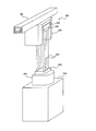
- FIGS. 3 and 4 are perspective views showing a FOUP transfer method.
- the lifting / lowering belt 240 is unwound by the lifting / lowering control unit 235 so that the gripping unit 250 is lowered to the position of the FOUP 400. And the fine adjustment of the position of the holding part 250 and the FOUP 400 is performed, and the FOUP 400 is held.
- the elevating belt 240 is wound up, and the grip portion 250 and the gripped FOUP 400 are moved up to the position of the main body portion 220. Then, the transport vehicle 200 travels again on the track 100, and the FOUP 400 is transported.
- the FOUP 400 is installed on the temporary storage shelf 520 at a position deviated to the side of the track 100.
- the elevating belt 240 is unwound by the elevating control unit 235, and the gripping unit 250 is lowered to the position of the FOUP 400.
- the FOUP 400 can be laterally transferred from the track unit 100.
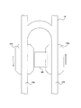
- FIG. 5 is a top view showing the positional relationship between the track, the transport vehicle, and the temporary storage shelf of the transport system according to this embodiment
- FIG. 6 is the track, the transport vehicle, and the temporary track of the transport system according to the present embodiment.
- It is a side view which shows the positional relationship of a storage shelf.
- FIG. 7 is a side view showing the positional relationship between the track, the transport vehicle, and the temporary storage shelf of the transport system according to the comparative example.
- a temporary storage shelf 520 is an example of a temporary storage shelf, and is provided between the first track 100a and the second track 100b that are provided side by side. It has been.
- the FOUP 400 can be transferred to the temporary storage shelf 520 by a transport vehicle 200a traveling on the first track 100a.
- the temporary storage shelf 520 is provided so as to at least partially overlap the carrier vehicle 200a to which the FOUP 400 can be transferred as viewed in the vertical direction.
- the conveyance vehicle 200b traveling on the track 100b opposite to the conveyance vehicle 200a is provided so as not to overlap (that is, to be separated).
- the temporary storage shelf 520 is provided at the same height as the temporary storage shelf 530. For this reason, the FOUP 400 transferred to the temporary storage shelf 520 has a height that does not interfere with the transport vehicle 200.
- the temporary storage shelf 520 is a temporary storage shelf that is provided on the side of the track and needs to be moved by the moving unit 230 for transferring articles, and is referred to as, for example, an STU (Side Truck Buffer).
- the temporary storage shelf 530 is a temporary storage shelf that is provided on the lower side of the track and does not need to be moved by the moving unit 230 for transferring articles, and is referred to as, for example, UTB (Under Truck Buffer).
- the distance A1 between the first track 1100a and the second track 1100b according to the comparative example can be expressed by the following formula (1).
- the width of the transport vehicle 1200a is B
- the width of the FOUP 400 is C
- the distance between the end of the transport vehicle 1200a and the FOUP 1400 loaded on the transport vehicle 1200a is D
- the temporary storage shelf is extended from the end of the transport vehicle 1200a.
- E is the distance to the FOUP 1400 transferred to 1520
- F is the distance from the end of the transport vehicle 1200b to the FOUP transferred to the temporary storage shelf 1520.
- distances D, E, and F are determined by the configuration of the transport vehicle 200 and the like.
- the distance A2 between the first track 100a and the second track 100b according to the present embodiment is expressed by the following formula (2) with respect to the comparative example described above. expressed.
- G is the distance from the FOUP 400 loaded on the transport vehicle 200a to the FOUP transferred to the temporary storage shelf 520.
- the temporary storage shelf 520 is provided at such a height that the transferred FOUP 400 does not interfere with the transport vehicle 200. For this reason, even when the distance between the first track 100a and the second track 100b is relatively narrow, interference between the transport vehicle 200 and the FOUP 400 of the temporary storage shelf 520 can be reliably prevented.
- interference between the transport vehicle 200 and the FOUP 400 of the temporary storage shelf 520 can also be prevented by increasing the distance between the first track 100a and the second track 100b.
- changing the laying position of the track 100 is extremely expensive.
- the transport system according to the present embodiment also has an effect of preventing such an increase in cost.
- the temporary storage shelf 520 is further provided at the same height as the temporary storage shelf 530. Therefore, the configuration of each buffer can be simplified as compared with the case where the temporary storage shelf 520 and the temporary storage shelf 530 are provided at different heights (see FIG. 7).
- the FOUP 400 is suitably transferred to the temporary storage shelf 520 provided between the tracks 100 while preventing the traveling transport vehicle 200 and the FOUP 400 from interfering with each other. Is possible.
Landscapes
- Engineering & Computer Science (AREA)
- Mechanical Engineering (AREA)
- Warehouses Or Storage Devices (AREA)
- Container, Conveyance, Adherence, Positioning, Of Wafer (AREA)
Abstract
搬送システムにおいて、軌道間に設けられた一時保管棚に対して好適に物品を移載することを目的とする。搬送システムは、互いに並んで設けられた2本の軌道(100a,100b)を有する軌道(100)と、2本の軌道の間に設けられた一時保管棚(520)と、軌道を走行すると共に、一時保管棚に物品(400)を移載可能な搬送車(200)とを備える。一時保管棚は、物品を移載しようとする搬送車と鉛直方向で見て少なくとも部分的に重なる位置、且つ移載された物品が搬送車と干渉しない高さに設けられている。
Description
本発明は、例えば半導体装置製造用の各種基板が収容された容器等の物品を、軌道に沿って走行する搬送車によって搬送する搬送システムの技術分野に関する。
この種の搬送システムとして、例えば天井に敷設された軌道上を複数の搬送車が走行することによって、物品を搬送するものがある。搬送車は、軌道に沿うように設けられた一時保管棚(例えば、バッファ等)との間で、物品の受け渡し(即ち、移載)が可能である。
物品の移載は、軌道の真下に位置するバッファに対してのみならず、軌道から見て横方向に位置するバッファに対しても行うことが可能である。例えば特許文献1では、平行に設けられた2本の軌道の間に一時保管棚を設けるという技術が提案されている。
上述したような搬送システムでは、半導体ウェハの大径化等に伴い物品が大型化している。このため、物品を搬送する搬送車の大型化も求められている。
しかしながら、上述した特許文献1に係る技術のような構成では、単に搬送車を大型化すると、搬送車と一時保管棚とが干渉してしまうおそれがある。これに対し、軌道の間隔を広げることで干渉を防止しようとすると、膨大なコストがかかってしまう。即ち、特許文献1に係る技術には、搬送車の大型化に柔軟に対応することができないという技術的問題点がある。
本発明は、例えば上述した問題点に鑑みなされたものであり、軌道間に設けられた一時保管棚に対して好適に物品を移載することが可能な搬送システムを提供することを課題とする。
本発明の一見地に係る搬送システムは上記課題を解決するために、軌道と、第1一時保管棚と、搬送車とを備えている。軌道は、互いに並んで設けられた第1軌道及び第2軌道を有する。第1一時保管棚は、鉛直方向で見て第1軌道及び第2軌道の間に設けられているように見える位置に設けられている。搬送車は、軌道を走行する本体部と、第1一時保管棚との間で物品を移載する移載部とを有している。第1一時保管棚は、第1軌道において第1一時保管棚との間で物品の移載作業を行っている搬送車の本体部と鉛直方向で見て一部が重なる位置、且つ第1一時保管棚に積載されている物品が第1軌道を走行する搬送車の本体部に干渉しない高さに設けられている。
この搬送システムによれば、その動作時には、例えば天井に敷設された軌道に沿って走行するOHT(Overhead Hoist Transport)等の搬送車によって、FOUP(Front Opening Unified Pod)等の物品が搬送される。軌道上には、複数の搬送車が配置されており、各搬送車は各々に与えられた搬送命令に基づいて物品を搬送する。
軌道は、互いに並ぶように設けられる第1軌道及び第2軌道を有している。例えば両軌道は、互いに平行に並ぶと共に比較的狭い間隔で設けられる。この両軌道の間には、物品を移載することが可能な第1一時保管棚が設けられている。第1一時保管棚は、軌道の側方に位置するように設けられており、搬送車は、例えば側方に伸長可能な移載機構を用いて、第1一時保管棚に物品を移載する。
特に、上述した第1一時保管棚は、第1軌道において物品を移載している搬送車と鉛直方向で見て少なくとも部分的に重なる位置、且つ第1一時保管棚に積載されている物品が、第1軌道を走行する搬送車に干渉しない高さに設けられている。例えば、第1一時保管棚は、搬送車の側方側に物品の幅より小さい幅だけずれた位置に設けられており、更には第1の軌道及び第2の軌道を走行する搬送車が第1一時保管棚に積載されている物品に干渉しないように、第1一時保管棚側の高さが調整されている。
ここで仮に、第1一時保管棚が搬送車の走行する高さと同じような高さに設けられているとすると、搬送車と第1一時保管棚に移載された物品に干渉しないためには、2本の軌道が、少なくとも物品の幅より離れて設けられることが求められる。より正確に言えば、2本の軌道間は、軌道から搬送車の端部までの距離、物品の幅及び移載時のマージン等を合計した距離だけ離れていることが求められる。
このような軌道間の距離は、敷設した当初では十分な距離(即ち、搬送車と第1一時保管棚に積載された物品とが互いに干渉しないような距離)とされていたとしても、例えば搬送車を大型化しようとすると十分な距離とは言えなくなってしまう。即ち、搬送車が大型化した分だけ第1一時保管棚側に近づくため、搬送車と第1一時保管棚に移載された物品とが互いに干渉するおそれが出てくる。
しかるに、上述したように、第1一時保管棚は、移載された物品が搬送車に干渉しない高さに設けられている。例えば、第1一時保管棚は、側方から見て、搬送車と第1一時保管棚に積載されている物品とが互いに重ならないまでに下方側に設けられている。このため、搬送車と第1一時保管棚とが互いに重なるような位置に設けられていたとしても、搬送車と第1一時保管棚に積載されている物品との干渉を確実に防止できる。
なお、第1軌道と第2軌道の間隔を広げることによっても、搬送車と第1一時保管棚の物品との干渉を防止できると考えられるが、軌道の敷設位置の変更には極めて大きなコストがかかってしまう。本発明は、このようなコストの増大を防止するという効果も有している。
以上説明したように、本発明の一見地に係る搬送システムによれば、走行する搬送車と物品との干渉を防止しつつ、軌道間に設けられた第1一時保管棚に対して好適に物品を移載することが可能である。
第1一時保管棚は、第2軌道において第1一時保管棚との間で物品の移載作業を行っている搬送車の本体部と鉛直方向で見て重ならない位置に設けられていてもよい。
軌道は、第1軌道にある搬送車と、第2軌道にある搬送車との間の、軌道の延在方向に直交する水平方向の距離が、物品の幅より狭くなるように設けられていてもよい。
この場合、第1軌道を走行する第1搬送車の第1一時保管棚側の端部と、第2軌道を走行する第2搬送車の第1一時保管棚側の端部との、軌道の延在方向に直交する水平方向の距離が、物品の幅より狭くされる。なお、ここでの「軌道の延在方向に直交する水平方向の距離」とは、異なる軌道を走行する搬送車同士が、互いに最も近づく際の距離を意味している。
このような場合であっても、第1一時保管棚は、搬送車と移載された物品とが互いに干渉しないような高さに設けられているため、何ら問題は生じない。即ち、軌道間の距離が狭く設定されている場合であっても、第1一時保管棚の高さが調整されているため、干渉を防止できる。従って、搬送車の大型化等に柔軟に対応することが可能である。
第1軌道及び第2軌道間の距離Aが、A=B+C-D+G+Fと表せる場合に、第1一時保管棚は、G<Dの関係を満たすように設けられてもよい。なお、Bは搬送車の幅であり、Cは物品の幅であり、Dは第1軌道にある搬送車の第1一時保管棚側の端部と搬送車に積載された物品との水平方向距離である。さらに、Fは第2軌道にある搬送車の第1一時保管棚側の端部から第1一時保管棚に積載されている物品までの水平方向距離であり、Gは第1軌道にある搬送車に積載された物品から第1一時保管棚に積載されている物品までの水平方向距離である。
この場合は、搬送車に積載された物品から見て、搬送車の第1一時保管棚側の端部までの距離(即ち、距離D)が、第1一時保管棚に移載された物品までの距離(即ち、距離G)より大きくなるように、第1一時保管棚の位置が設定されている。即ち、第1一時保管棚に積載されている物品が、搬送車の端部よりも搬送車内側に位置するような位置とされている。よって、第1軌道と第2軌道の間の距離は比較的狭いものとなる。
このような場合であっても、第1一時保管棚は、搬送車と第1一時保管棚に積載された物品とが互いに干渉しないような高さに設けられているので、特に問題は生じない。即ち、軌道間の距離が狭く設定されている場合であっても、第1一時保管棚の高さが調整されているので、干渉を防止できる。従って、搬送車の大型化等に柔軟に対応できる。
搬送システムは、第1軌道及び第2軌道の少なくとも一方の真下に設けられた第2一時保管棚を更に備えていてもよい。その場合、第1一時保管棚は、第2一時保管棚と同じ高さに設けられている。
この場合、搬送車の真下に位置する第2一時保管棚が設けられており、搬送車は、第1一時保管棚と同様に、第2一時保管棚に対しても物品の移載を行う。
そして特に、第1一時保管棚は、上述した第2一時保管棚と同じ高さに設けられている。従って、第1一時保管棚及び第2一時保管棚を互いに異なる高さに設ける場合と比べて、各バッファの構成を簡単にできる。
なお、本態様の「同じ高さ」とは、第1一時保管棚の高さと第2一時保管棚の高さとが完全に同一になる場合のみを指すものではなく、上述した本態様の効果が発揮できるまでに、互いの高さが近いことを意味している。
本発明の他の見地に係る搬送システムは、軌道と、第1一時保管棚と、天井搬送車とを備えている。軌道は、互いに並んで設けられた第1軌道及び第2軌道を有する。第1一時保管棚は、鉛直方向で見て第1軌道及び第2軌道の間にあるように見える位置で、かつ、第1軌道及び第2軌道の下方に設けられている。天井搬送車は、軌道から吊り下げられた状態で走行する本体部と、第1一時保管棚との間で物品を移載可能な移載部とを有している。第1一時保管棚は、第1軌道において第1一時保管棚との間で物品の移載作業を行っている搬送車の本体部と鉛直方向で見て一部が重なり、第2軌道において第1一時保管棚との間で物品の移載作業を行っている搬送車の本体部と鉛直方向で見て重ならない位置に配置されている。第1一時保管棚は、第1一時保管棚に積載されている物品が第1軌道を走行する搬送車の本体部に干渉しない高さに設けられている。
移載部は、物品を側方に移動させる側方移動部と、側方移動部に設けられ物品を昇降させる昇降部とを有していてもよい。
本発明の作用及び他の利得は次に説明する発明を実施するための形態から明らかにされる。
以下では、本発明の実施形態について図を参照しつつ説明する。
1.搬送システムの全体構成
先ず、本実施形態に係る搬送システムの全体構成について、図1を参照して説明する。ここに図1は、本実施形態に係る搬送システムの全体構成を示す平面図である。
先ず、本実施形態に係る搬送システムの全体構成について、図1を参照して説明する。ここに図1は、本実施形態に係る搬送システムの全体構成を示す平面図である。
図1において、本実施形態に係る搬送システムは、軌道100と、搬送車200と、コントローラ300とを備えて構成されている。
軌道100は、例えば天井に敷設されており、アルミニウムやステンレス等の金属から構成される。
搬送車200は、軌道100上に複数配置されており、軌道100上を走行することによって物品であるFOUPを搬送することが可能である。尚、ここでは搬送車200の進行方向を明確にするため、搬送車200の前方部分を鋭角なものとして概念的に図示している。
搬送車200は更に、車上コントローラ205を夫々有している。車上コントローラ205は、コントローラ300から搬送指令を受け取り、搬送車200の走行を制御する。尚、車上コントローラ205は、搬送車200の走行を制御するだけでなく、搬送車200に備えられた各機器を総括的に制御するという機能も有している。
コントローラ300は、例えば演算回路やメモリ等を含んで構成されており、車上コントローラ205を介して、搬送車200に搬送指令を与えることが可能に構成されている。
尚、ここでの図示は省略しているが、軌道100に沿った位置には、FOUPを一時的に保管するバッファが複数設けられている。このバッファの構成については、後に詳述する。
2.搬送車の具体的な構成
次に、搬送車のより具体的な構成について、図2を参照して説明する。ここに図2は、搬送車の構成を示す側面図である
次に、搬送車のより具体的な構成について、図2を参照して説明する。ここに図2は、搬送車の構成を示す側面図である
図2において、搬送車200は、走行部210、本体部220、移動部230、昇降制御部235、昇降ベルト240及び把持部250を備えて構成されている。
搬送車200は、走行部210が例えばリニアモータ等によって推進力を与えることで、走行ローラ215が転動されつつ、軌道100に沿って走行する。走行部210の下面には、本体部220が吊り下がる形で取り付けられている。
本体部220には、移動部230が取り付けられている。移動部230は、軌道100の側方(即ち、図における左右方向)に移動することが可能である。移動部230の下面には、昇降制御部235が取り付けられている。
昇降制御部235の下面には、FOUPを把持する把持部250が昇降ベルト240によって取り付けられている。把持部250は、昇降ベルト240を巻き出す或いは巻き取ることで、本体部220に対し昇降可能である。
3.搬送車によるFOUPの移載方法
次に、搬送車によるFOUPの移載方法について、図3及び図4を参照して説明する。ここに図3及び図4は夫々、FOUPの移載方法を示す斜視図である。
次に、搬送車によるFOUPの移載方法について、図3及び図4を参照して説明する。ここに図3及び図4は夫々、FOUPの移載方法を示す斜視図である。
図3において、搬送車200が軌道100の真下に位置するポート510上のFOUP400を移載する際には、先ず搬送車200が軌道100上を走行して、ポート510上に設置されたFOUP400の上方に停止する。
続いて、図に示すように、昇降制御部235によって昇降ベルト240が巻き出されることで把持部250がFOUP400の位置まで降下する。そして、把持部250とFOUP400との位置の微調整が行われ、FOUP400が把持される。
FOUP400が把持されると、昇降ベルト240が巻き取られ、把持部250及び把持されたFOUP400が本体部220の位置まで上昇する。そして、再び搬送車200が軌道100上を走行して、FOUP400が搬送される。
図4において、FOUP400が軌道100の側方にそれた位置にある一時保管棚520に設置されている場合を説明する。移動部230が軌道100の側方に移動した後に、昇降制御部235によって昇降ベルト240が巻き出され、把持部250がFOUP400の位置まで降下する。このように動作することで、軌道部100からFOUP400の横移載を行うことが可能となる。
4.搬送システムのバッファの構成
次に、本実施形態に係る搬送システムのバッファの構成について、図5から図7を参照して詳細に説明する。ここに図5は、本実施形態に係る搬送システムの軌道、搬送車及び一時保管棚の位置関係を示す上面図であり、図6は、本実施形態に係る搬送システムの軌道、搬送車及び一時保管棚の位置関係を示す側面図である。また図7は、比較例に係る搬送システムの軌道、搬送車及び一時保管棚の位置関係を示す側面図である。
次に、本実施形態に係る搬送システムのバッファの構成について、図5から図7を参照して詳細に説明する。ここに図5は、本実施形態に係る搬送システムの軌道、搬送車及び一時保管棚の位置関係を示す上面図であり、図6は、本実施形態に係る搬送システムの軌道、搬送車及び一時保管棚の位置関係を示す側面図である。また図7は、比較例に係る搬送システムの軌道、搬送車及び一時保管棚の位置関係を示す側面図である。
4.1.本実施形態の一時保管棚の位置
図5において、本実施形態に係る一時保管棚520は、一時保管棚の一例であり、互いに並んで設けられた第1軌道100a及び第2軌道100b間に設けられている。一時保管棚520には、第1軌道100aを走行する搬送車200aによって、FOUP400が移載可能とされている。尚、一時保管棚520は、図を見ても分かるように、FOUP400を移載可能である搬送車200aに対して、鉛直方向で見て、少なくとも部分的に重なるように設けられている。一方で、搬送車200aとは反対側の軌道100bを走行する搬送車200bに対しては、重ならないように(即ち、離間するように)設けられている。
図5において、本実施形態に係る一時保管棚520は、一時保管棚の一例であり、互いに並んで設けられた第1軌道100a及び第2軌道100b間に設けられている。一時保管棚520には、第1軌道100aを走行する搬送車200aによって、FOUP400が移載可能とされている。尚、一時保管棚520は、図を見ても分かるように、FOUP400を移載可能である搬送車200aに対して、鉛直方向で見て、少なくとも部分的に重なるように設けられている。一方で、搬送車200aとは反対側の軌道100bを走行する搬送車200bに対しては、重ならないように(即ち、離間するように)設けられている。
図6において、本実施形態に係る一時保管棚520は、一時保管棚530と同じ高さに設けられている。このため、一時保管棚520に移載されたFOUP400は、搬送車200とは干渉しない高さとなる。
なお、一時保管棚520は、軌道側方に設けられ、物品の移載に移動部230による移動が必要な一時保管棚であり、例えば、STU(Side Truck Buffer)と称する。また、一時保管棚530は、軌道下側に設けられ、物品の移載に移動部230による移動が不要な一時保管棚であり、例えば、UTB(Under Truck Buffer)と称する。
なお、一時保管棚520は、軌道側方に設けられ、物品の移載に移動部230による移動が必要な一時保管棚であり、例えば、STU(Side Truck Buffer)と称する。また、一時保管棚530は、軌道下側に設けられ、物品の移載に移動部230による移動が不要な一時保管棚であり、例えば、UTB(Under Truck Buffer)と称する。
4.2.比較例における一時保管棚の位置及び寸法関係
図7において、仮に一時保管棚1520が、より高い位置に設けられていたとすると、一時保管棚1520に移載されたFOUP1400及び搬送車1200a及び1200bは、水平方向で見て、互いに重なる位置に存在することになる。よって、FOUP1400と搬送車1200a又は搬送車1200bとが干渉しないようにするためには、第1軌道1100a及び第2軌道1100b間の距離が比較的大きいことが求められる。
図7において、仮に一時保管棚1520が、より高い位置に設けられていたとすると、一時保管棚1520に移載されたFOUP1400及び搬送車1200a及び1200bは、水平方向で見て、互いに重なる位置に存在することになる。よって、FOUP1400と搬送車1200a又は搬送車1200bとが干渉しないようにするためには、第1軌道1100a及び第2軌道1100b間の距離が比較的大きいことが求められる。
具体的には、比較例に係る第1軌道1100a及び第2軌道1100b間の距離A1は、以下の数式(1)で表すことができる。なお、この場合、搬送車1200aの幅をB、FOUP400の幅をC、搬送車1200aの端部と搬送車1200aに積載されたFOUP1400との間隔をD、搬送車1200aの端部から一時保管棚1520に移載されたFOUP1400までの距離をE、搬送車1200bの端部から一時保管棚1520に移載されたFOUPまでの距離をFとしている。
A1=B+C+E+F ・・・(1)
尚、距離D、E及びFは、夫々搬送車200の構成等によって決定される。
4.3.本実施例における一時保管棚の寸法関係
図6に戻り、上述した比較例に対して、本実施形態に係る第1軌道100a及び第2軌道100b間の距離A2は、以下の数式(2)で表される。なお、Gは、搬送車200aに積載されたFOUP400から一時保管棚520に移載されたFOUPまでの距離である。
図6に戻り、上述した比較例に対して、本実施形態に係る第1軌道100a及び第2軌道100b間の距離A2は、以下の数式(2)で表される。なお、Gは、搬送車200aに積載されたFOUP400から一時保管棚520に移載されたFOUPまでの距離である。
A2=B+C-D+G+F ・・・(2)
数式(2)に、数式(1)を代入すると、以下の数式(3)が成り立つ。
A2=A1-E-D+G ・・・(3)
ここで、図からも分かるように、G<Dなので、A2<A1の関係が成り立つ。即ち、本実施形態に係る搬送システムによれば、一時保管棚520の位置を下側にずらすことによって、第1軌道100a及び第2軌道100b間の距離を小さくできる。
このような軌道間の距離は、敷設した当初では十分な距離とされていたとしても、例えば搬送車200を大型化しようとすると十分な距離とは言えなくなってしまう。即ち、搬送車200が大型化した分だけ一時保管棚520側に近づくため、搬送車200と一時保管棚520に移載されたFOUP400とが干渉するおそれが出てくる。
これに対し本実施形態では、上述したように、一時保管棚520は、移載されたFOUP400が搬送車200と干渉しないような高さに設けられている。このため、第1軌道100a及び第2軌道100b間の距離が比較的狭い場合であっても、搬送車200と一時保管棚520のFOUP400との干渉を確実に防止できる。
なお、第1軌道100a及び第2軌道100b間の距離を広げることによっても、搬送車200と一時保管棚520のFOUP400との干渉を防止できると考えられるかもしれない。しかし、軌道100の敷設位置の変更には極めて大きなコストがかかってしまう。本実施形態に係る搬送システムは、このようなコストの増大を防止するという効果も有している。
本実施形態では更に、一時保管棚520は、一時保管棚530と同じ高さに設けられている。このため、一時保管棚520及び一時保管棚530を互いに異なる高さに設ける場合(図7参照)と比べて、各バッファの構成を簡単にできる。
以上説明したように、本発明の搬送システムによれば、走行する搬送車200とFOUP400との干渉を防止しつつ、軌道100間に設けられた一時保管棚520に対して好適にFOUP400を移載することが可能である。
本発明は、上述した実施形態に限られるものではなく、特許請求の範囲及び明細書全体から読み取れる発明の要旨或いは思想に反しない範囲で適宜変更可能であり、そのような変更を伴う搬送システムもまた本発明の技術的範囲に含まれるものである。
100 軌道
100a 第1軌道
100b 第2軌道
200 搬送車
210 走行部
215 走行ローラ
220 本体部
230 移動部
240 昇降ベルト
250 把持部
300 コントローラ
400 FOUP
510 ポート
520 一時保管棚
530 一時保管棚
100a 第1軌道
100b 第2軌道
200 搬送車
210 走行部
215 走行ローラ
220 本体部
230 移動部
240 昇降ベルト
250 把持部
300 コントローラ
400 FOUP
510 ポート
520 一時保管棚
530 一時保管棚
Claims (15)
- 互いに並んで設けられた第1軌道及び第2軌道を有する軌道と、
鉛直方向で見て前記第1軌道及び前記第2軌道の間にある位置に設けられた第1一時保管棚と、
前記軌道を走行する本体部と、前記第1一時保管棚との間で物品を移載する移載部とを有している搬送車と、
を備え、
前記第1一時保管棚は、前記第1軌道において前記第1一時保管棚との間で前記物品の移載作業を行っているときに搬送車の前記本体部と鉛直方向で見て一部が重なる位置、且つ前記第1一時保管棚に積載されている物品が前記第1軌道を走行する搬送車の前記本体部に干渉しない高さに設けられている
搬送システム。 - 前記第1一時保管棚は、前記第2軌道において前記第1一時保管棚との間で前記物品の移載作業を行っているときの搬送車の本体部と鉛直方向で見て重ならない位置に設けられている、請求項1に記載の搬送システム。
- 前記軌道は、前記第1軌道にある搬送車と、前記第2軌道にある搬送車との間の、前記軌道に直交する水平方向の距離が、前記物品の幅より狭くなるように設けられている、請求項2に記載の搬送システム。
- 前記第1軌道及び前記第2軌道間の距離Aが、前記搬送車の幅をB、前記物品の幅をC、前記第1軌道にある搬送車の前記第1一時保管棚側の端部と当該搬送車に積載された前記物品との水平方向距離をD、前記第2軌道にある搬送車の前記第1一時保管棚側の端部と前記第1一時保管棚に積載されている前記物品との間の水平方向距離をF、前記第1軌道にある搬送車に積載された前記物品と前記第1一時保管棚に積載されている物品との間の水平方向距離をGとして、
A=B+C-D+G+F
と表せる場合に、
前記第1一時保管棚は、
G<D
の関係を満たすように設けられている、請求項3に記載の搬送システム。 - 前記第1軌道及び前記第2軌道の一方の真下に設けられた第2一時保管棚を更に備え、
前記第1一時保管棚は、前記第2一時保管棚と同じ高さに設けられている、請求項4に記載の搬送システム。 - 前記第1軌道及び前記第2軌道の一方の真下に設けられた第2一時保管棚を更に備え、
前記第1一時保管棚は、前記第2一時保管棚と同じ高さに設けられている、請求項2に記載の搬送システム。 - 前記第1軌道及び前記第2軌道の一方の真下に設けられた第2一時保管棚を更に備え、
前記第1一時保管棚は、前記第2一時保管棚と同じ高さに設けられている、請求項3に記載の搬送システム。 - 前記軌道は、前記第1軌道にある搬送車と、前記第2軌道にある搬送車との間の、前記軌道に直交する水平方向の距離が、前記物品の幅より狭くなるように設けられている、請求項1に記載の搬送システム。
- 前記第1軌道及び前記第2軌道間の距離Aが、前記搬送車の幅をB、前記物品の幅をC、前記第1軌道にある搬送車の前記第1一時保管棚側の端部と当該搬送車に積載された前記物品との水平方向距離をD、前記第2軌道にある搬送車の前記第1一時保管棚側の端部と前記第1一時保管棚に積載されている前記物品との間の水平方向距離をF、前記第1軌道にある搬送車に積載された前記物品と前記第1一時保管棚に積載されている物品との間の水平方向距離をGとして、
A=B+C-D+G+F
と表せる場合に、
前記第1一時保管棚は、
G<D
の関係を満たすように設けられている、請求項8に記載の搬送システム。 - 前記第1軌道及び前記第2軌道の一方の真下に設けられた第2一時保管棚を更に備え、
前記第1一時保管棚は、前記第2一時保管棚と同じ高さに設けられている、請求項9に記載の搬送システム。 - 前記第1軌道及び前記第2軌道の一方の真下に設けられた第2一時保管棚を更に備え、
前記第1一時保管棚は、前記第2一時保管棚と同じ高さに設けられている、請求項8に記載の搬送システム。 - 前記第1軌道及び前記第2軌道の一方の真下に設けられた第2一時保管棚を更に備え、
前記第1一時保管棚は、前記第2一時保管棚と同じ高さに設けられている、請求項9に記載の搬送システム。 - 前記第1軌道及び前記第2軌道の一方の真下に設けられた第2一時保管棚を更に備え、
前記第1一時保管棚は、前記第2一時保管棚と同じ高さに設けられている、請求項1に記載の搬送システム。 - 互いに並んで設けられた第1軌道及び第2軌道を有する軌道と、
鉛直方向で見て前記第1軌道及び前記第2軌道の間にあるように見える位置で、かつ、前記第1軌道及び前記第2軌道の下方に設けられた第1一時保管棚と、
前記軌道から吊り下げられた状態で走行する本体部と、前記第1一時保管棚との間で物品を移載可能な移載部とを有している天井搬送車と
を備え、
前記第1一時保管棚は、前記第1軌道において前記第1一時保管棚との間で前記物品の移載作業を行っている搬送車の前記本体部と鉛直方向で見て一部が重なり、前記第2軌道において前記第1一時保管棚との間で前記物品の移載作業を行っている搬送車の前記本体部と鉛直方向で見て重ならない位置に配置されており、
前記第1一時保管棚は、前記第1一時保管棚に積載されている物品が前記第1軌道を走行する搬送車の前記本体部に干渉しない高さに設けられている、
搬送システム。 - 前記移載部は、前記物品を側方に移動させる側方移動部と、前記側方移動部に設けられ物品を昇降させる昇降部とを有している、請求項14に記載の搬送システム。
Applications Claiming Priority (2)
| Application Number | Priority Date | Filing Date | Title |
|---|---|---|---|
| JP2010-168087 | 2010-07-27 | ||
| JP2010168087A JP2012025573A (ja) | 2010-07-27 | 2010-07-27 | 搬送システム |
Publications (1)
| Publication Number | Publication Date |
|---|---|
| WO2012014561A1 true WO2012014561A1 (ja) | 2012-02-02 |
Family
ID=45529782
Family Applications (1)
| Application Number | Title | Priority Date | Filing Date |
|---|---|---|---|
| PCT/JP2011/062355 Ceased WO2012014561A1 (ja) | 2010-07-27 | 2011-05-30 | 搬送システム |
Country Status (3)
| Country | Link |
|---|---|
| JP (1) | JP2012025573A (ja) |
| TW (1) | TW201212149A (ja) |
| WO (1) | WO2012014561A1 (ja) |
Cited By (1)
| Publication number | Priority date | Publication date | Assignee | Title |
|---|---|---|---|---|
| CN109791906A (zh) * | 2016-09-26 | 2019-05-21 | 村田机械株式会社 | 顶棚搬运系统以及顶棚搬运车 |
Families Citing this family (3)
| Publication number | Priority date | Publication date | Assignee | Title |
|---|---|---|---|---|
| US9415934B2 (en) * | 2014-05-14 | 2016-08-16 | Murata Machinery, Ltd. | Transport system and transport method |
| WO2019021708A1 (ja) * | 2017-07-24 | 2019-01-31 | 村田機械株式会社 | 自動倉庫システム、及び自動倉庫システムの制御方法 |
| WO2020195240A1 (ja) * | 2019-03-22 | 2020-10-01 | 村田機械株式会社 | 搬送車システム |
Citations (3)
| Publication number | Priority date | Publication date | Assignee | Title |
|---|---|---|---|---|
| JPS62269892A (ja) * | 1986-05-15 | 1987-11-24 | 三菱重工業株式会社 | 立体コンテナヤ−ド |
| JP2008100835A (ja) * | 2006-10-20 | 2008-05-01 | Asyst Technologies Japan Inc | 搬送システム |
| JP2009120299A (ja) * | 2007-11-13 | 2009-06-04 | Murata Mach Ltd | 天井走行車システムとそのバッファの施工方法 |
-
2010
- 2010-07-27 JP JP2010168087A patent/JP2012025573A/ja active Pending
-
2011
- 2011-05-30 WO PCT/JP2011/062355 patent/WO2012014561A1/ja not_active Ceased
- 2011-07-18 TW TW100125305A patent/TW201212149A/zh unknown
Patent Citations (3)
| Publication number | Priority date | Publication date | Assignee | Title |
|---|---|---|---|---|
| JPS62269892A (ja) * | 1986-05-15 | 1987-11-24 | 三菱重工業株式会社 | 立体コンテナヤ−ド |
| JP2008100835A (ja) * | 2006-10-20 | 2008-05-01 | Asyst Technologies Japan Inc | 搬送システム |
| JP2009120299A (ja) * | 2007-11-13 | 2009-06-04 | Murata Mach Ltd | 天井走行車システムとそのバッファの施工方法 |
Cited By (4)
| Publication number | Priority date | Publication date | Assignee | Title |
|---|---|---|---|---|
| CN109791906A (zh) * | 2016-09-26 | 2019-05-21 | 村田机械株式会社 | 顶棚搬运系统以及顶棚搬运车 |
| JPWO2018055883A1 (ja) * | 2016-09-26 | 2019-10-03 | 村田機械株式会社 | 天井搬送システム、及び天井搬送車 |
| US11052926B2 (en) | 2016-09-26 | 2021-07-06 | Murata Machinery, Ltd. | Overhead transport system and overhead transport vehicle |
| CN109791906B (zh) * | 2016-09-26 | 2023-11-24 | 村田机械株式会社 | 顶棚搬运系统以及顶棚搬运车 |
Also Published As
| Publication number | Publication date |
|---|---|
| TW201212149A (en) | 2012-03-16 |
| JP2012025573A (ja) | 2012-02-09 |
Similar Documents
| Publication | Publication Date | Title |
|---|---|---|
| JP5429570B2 (ja) | 物品搬送設備 | |
| EP3476772B1 (en) | Conveyance system | |
| CN103547498B (zh) | 有轨台车系统 | |
| JP5316907B2 (ja) | 物品搬送設備 | |
| JP5472209B2 (ja) | 物品搬送設備 | |
| JP4378655B2 (ja) | 物品処理設備 | |
| CN110831873B (zh) | 搬运系统以及搬运方法 | |
| JP2018070327A (ja) | 物品搬送設備 | |
| TW201637982A (zh) | 搬送台車及搬送台車系統 | |
| WO2013183376A1 (ja) | 搬送システム及び搬送システムでの物品の一時保管方法 | |
| US9896283B2 (en) | Article transport facility | |
| JP7323059B2 (ja) | 搬送車システム | |
| WO2022149305A1 (ja) | 天井保管システム | |
| WO2012014561A1 (ja) | 搬送システム | |
| JP4636379B2 (ja) | 懸垂式昇降搬送台車における物品の授受方法並びに装置 | |
| US20070284217A1 (en) | Transportation system and transportation method | |
| TW202144257A (zh) | 物品搬送設備 | |
| CN111741911B (zh) | 搬运装置 | |
| JP5772055B2 (ja) | 搬送車押し上げ装置 | |
| JP2012086933A (ja) | 落下防止柵及び搬送システム |
Legal Events
| Date | Code | Title | Description |
|---|---|---|---|
| 121 | Ep: the epo has been informed by wipo that ep was designated in this application |
Ref document number: 11812154 Country of ref document: EP Kind code of ref document: A1 |
|
| NENP | Non-entry into the national phase |
Ref country code: DE |
|
| 122 | Ep: pct application non-entry in european phase |
Ref document number: 11812154 Country of ref document: EP Kind code of ref document: A1 |