WO2012014274A1 - ボタン取付部材及びボタン構成体 - Google Patents
ボタン取付部材及びボタン構成体 Download PDFInfo
- Publication number
- WO2012014274A1 WO2012014274A1 PCT/JP2010/062555 JP2010062555W WO2012014274A1 WO 2012014274 A1 WO2012014274 A1 WO 2012014274A1 JP 2010062555 W JP2010062555 W JP 2010062555W WO 2012014274 A1 WO2012014274 A1 WO 2012014274A1
- Authority
- WO
- WIPO (PCT)
- Prior art keywords
- post
- button
- base portion
- base
- opening
- Prior art date
- Legal status (The legal status is an assumption and is not a legal conclusion. Google has not performed a legal analysis and makes no representation as to the accuracy of the status listed.)
- Ceased
Links
Images






Classifications
-
- A—HUMAN NECESSITIES
- A44—HABERDASHERY; JEWELLERY
- A44B—BUTTONS, PINS, BUCKLES, SLIDE FASTENERS, OR THE LIKE
- A44B1/00—Buttons
- A44B1/06—Assembling of buttons
-
- A—HUMAN NECESSITIES
- A44—HABERDASHERY; JEWELLERY
- A44B—BUTTONS, PINS, BUCKLES, SLIDE FASTENERS, OR THE LIKE
- A44B1/00—Buttons
- A44B1/08—Constructional characteristics
-
- A—HUMAN NECESSITIES
- A44—HABERDASHERY; JEWELLERY
- A44B—BUTTONS, PINS, BUCKLES, SLIDE FASTENERS, OR THE LIKE
- A44B1/00—Buttons
- A44B1/18—Buttons adapted for special ways of fastening
- A44B1/185—Buttons adapted for special ways of fastening with quick, thread-like, anchoring means avoiding the use of a separate needle and thread
-
- A—HUMAN NECESSITIES
- A44—HABERDASHERY; JEWELLERY
- A44B—BUTTONS, PINS, BUCKLES, SLIDE FASTENERS, OR THE LIKE
- A44B1/00—Buttons
- A44B1/18—Buttons adapted for special ways of fastening
- A44B1/42—Buttons adapted for special ways of fastening with deformable prongs
-
- A—HUMAN NECESSITIES
- A44—HABERDASHERY; JEWELLERY
- A44B—BUTTONS, PINS, BUCKLES, SLIDE FASTENERS, OR THE LIKE
- A44B17/00—Press-button or snap fasteners
- A44B17/0029—Press-button fasteners made of plastics
- A44B17/0035—Their fastening
-
- A—HUMAN NECESSITIES
- A44—HABERDASHERY; JEWELLERY
- A44B—BUTTONS, PINS, BUCKLES, SLIDE FASTENERS, OR THE LIKE
- A44B17/00—Press-button or snap fasteners
- A44B17/0041—Press-button fasteners consisting of two parts
-
- Y—GENERAL TAGGING OF NEW TECHNOLOGICAL DEVELOPMENTS; GENERAL TAGGING OF CROSS-SECTIONAL TECHNOLOGIES SPANNING OVER SEVERAL SECTIONS OF THE IPC; TECHNICAL SUBJECTS COVERED BY FORMER USPC CROSS-REFERENCE ART COLLECTIONS [XRACs] AND DIGESTS
- Y10—TECHNICAL SUBJECTS COVERED BY FORMER USPC
- Y10T—TECHNICAL SUBJECTS COVERED BY FORMER US CLASSIFICATION
- Y10T24/00—Buckles, buttons, clasps, etc.
- Y10T24/36—Button with fastener
- Y10T24/3611—Deflecting prong or rivet
-
- Y—GENERAL TAGGING OF NEW TECHNOLOGICAL DEVELOPMENTS; GENERAL TAGGING OF CROSS-SECTIONAL TECHNOLOGIES SPANNING OVER SEVERAL SECTIONS OF THE IPC; TECHNICAL SUBJECTS COVERED BY FORMER USPC CROSS-REFERENCE ART COLLECTIONS [XRACs] AND DIGESTS
- Y10—TECHNICAL SUBJECTS COVERED BY FORMER USPC
- Y10T—TECHNICAL SUBJECTS COVERED BY FORMER US CLASSIFICATION
- Y10T24/00—Buckles, buttons, clasps, etc.
- Y10T24/36—Button with fastener
- Y10T24/3611—Deflecting prong or rivet
- Y10T24/3613—Anvil or plate
-
- Y—GENERAL TAGGING OF NEW TECHNOLOGICAL DEVELOPMENTS; GENERAL TAGGING OF CROSS-SECTIONAL TECHNOLOGIES SPANNING OVER SEVERAL SECTIONS OF THE IPC; TECHNICAL SUBJECTS COVERED BY FORMER USPC CROSS-REFERENCE ART COLLECTIONS [XRACs] AND DIGESTS
- Y10—TECHNICAL SUBJECTS COVERED BY FORMER USPC
- Y10T—TECHNICAL SUBJECTS COVERED BY FORMER US CLASSIFICATION
- Y10T24/00—Buckles, buttons, clasps, etc.
- Y10T24/36—Button with fastener
- Y10T24/3611—Deflecting prong or rivet
- Y10T24/3615—Integral
-
- Y—GENERAL TAGGING OF NEW TECHNOLOGICAL DEVELOPMENTS; GENERAL TAGGING OF CROSS-SECTIONAL TECHNOLOGIES SPANNING OVER SEVERAL SECTIONS OF THE IPC; TECHNICAL SUBJECTS COVERED BY FORMER USPC CROSS-REFERENCE ART COLLECTIONS [XRACs] AND DIGESTS
- Y10—TECHNICAL SUBJECTS COVERED BY FORMER USPC
- Y10T—TECHNICAL SUBJECTS COVERED BY FORMER US CLASSIFICATION
- Y10T24/00—Buckles, buttons, clasps, etc.
- Y10T24/45—Separable-fastener or required component thereof [e.g., projection and cavity to complete interlock]
- Y10T24/45005—Separable-fastener or required component thereof [e.g., projection and cavity to complete interlock] with third detached member completing interlock [e.g., hook type]
- Y10T24/45037—Separable-fastener or required component thereof [e.g., projection and cavity to complete interlock] with third detached member completing interlock [e.g., hook type] for apparel and related accessories
- Y10T24/45042—Button, button related
-
- Y—GENERAL TAGGING OF NEW TECHNOLOGICAL DEVELOPMENTS; GENERAL TAGGING OF CROSS-SECTIONAL TECHNOLOGIES SPANNING OVER SEVERAL SECTIONS OF THE IPC; TECHNICAL SUBJECTS COVERED BY FORMER USPC CROSS-REFERENCE ART COLLECTIONS [XRACs] AND DIGESTS
- Y10—TECHNICAL SUBJECTS COVERED BY FORMER USPC
- Y10T—TECHNICAL SUBJECTS COVERED BY FORMER US CLASSIFICATION
- Y10T24/00—Buckles, buttons, clasps, etc.
- Y10T24/45—Separable-fastener or required component thereof [e.g., projection and cavity to complete interlock]
- Y10T24/45225—Separable-fastener or required component thereof [e.g., projection and cavity to complete interlock] including member having distinct formations and mating member selectively interlocking therewith
- Y10T24/45471—Projection having movable connection between components thereof or variable configuration
- Y10T24/45524—Projection having movable connection between components thereof or variable configuration including resiliently biased projection component or surface segment
- Y10T24/45545—Projection having movable connection between components thereof or variable configuration including resiliently biased projection component or surface segment forming total external surface of projection
- Y10T24/4555—Projection having movable connection between components thereof or variable configuration including resiliently biased projection component or surface segment forming total external surface of projection and encircling hollow central area
- Y10T24/45555—Projection having movable connection between components thereof or variable configuration including resiliently biased projection component or surface segment forming total external surface of projection and encircling hollow central area having separate mounting means inserted into area
- Y10T24/4556—Plastic deformation of means or surface required for mounting
-
- Y—GENERAL TAGGING OF NEW TECHNOLOGICAL DEVELOPMENTS; GENERAL TAGGING OF CROSS-SECTIONAL TECHNOLOGIES SPANNING OVER SEVERAL SECTIONS OF THE IPC; TECHNICAL SUBJECTS COVERED BY FORMER USPC CROSS-REFERENCE ART COLLECTIONS [XRACs] AND DIGESTS
- Y10—TECHNICAL SUBJECTS COVERED BY FORMER USPC
- Y10T—TECHNICAL SUBJECTS COVERED BY FORMER US CLASSIFICATION
- Y10T24/00—Buckles, buttons, clasps, etc.
- Y10T24/45—Separable-fastener or required component thereof [e.g., projection and cavity to complete interlock]
- Y10T24/45225—Separable-fastener or required component thereof [e.g., projection and cavity to complete interlock] including member having distinct formations and mating member selectively interlocking therewith
- Y10T24/4588—Means for mounting projection or cavity portion
- Y10T24/45906—Means for mounting projection or cavity portion having component of means permanently deformed during mounting operation
- Y10T24/45911—Means for mounting projection or cavity portion having component of means permanently deformed during mounting operation and formed from or fixedly attached to projection or cavity portion
- Y10T24/45916—Cooperates with detached component of means
Definitions
- the present invention relates to a button attachment member and a button structure, and more particularly, a synthetic resin button attachment member used for attaching a button such as a female snap, a male snap, or a decorative button to a cloth, and such a button attachment member. Relates to a button structure comprising a button and a button.
- a button attachment member having a disk-like base portion and a post portion that protrudes from the base portion and tapers is generally used.
- a button mounting member After placing the button mounting member on the lower die below the horizontally arranged fabric and holding the button on the upper die above the fabric, Lower the upper die.
- the post portion of the button mounting member penetrates the fabric upward, and then protrudes through the button mounting opening.
- the button is fixed on the cloth by caulking the tip side portion of the post portion with the punch of the upper die.
- the button mounting member made of a synthetic resin is generally manufactured by injection molding in which a molten thermoplastic resin is injected into a mold and cooled and solidified, and the post portion secures strength during caulking, It is necessary to make it thick (large diameter) to some extent.
- the button mounting member to be injection-molded has a problem that voids (sink nests) are likely to occur inside the relatively thick post portion. If the amount of voids generated is large, when the button is attached to the cloth with the button attachment member, the post part may be cracked when crimped, or the button attachment force may not reach the expected value. Moreover, since the amount of voids generated varies, the button mounting force may also vary. Note that if the material temperature, mold temperature, cooling time, etc. at the time of injection molding are changed so as not to cause voids, sink marks (shrinkage) occur on the outer surface of the molded product, and the production efficiency decreases.
- the present invention has been made paying attention to the above-described problems, and an object thereof is to provide a button mounting member and a button structure in which voids hardly occur inside the post portion.
- a composition used when attaching a button having an opening for attachment to a fabric (the fabric includes woven fabric, fabric, nonwoven fabric, felt, leather, resin sheet, etc.).
- a button attachment member made of resin which has a plate-like base part and a post part protruding from the base part to the surface side of the base part, and penetrates the cloth when the button is attached to the cloth. And a post part that is deformed after passing through the cavity, the post part extending concentrically with the post part from the opening on the back surface of the base part to the closed end on the tip side of the post part, and the closed end of the cavity
- a button attachment member is provided that includes a solid portion between the tips of the post portions.
- the post part of the button mounting member by providing a cavity concentrically with the post part, one end in the axial direction is opened on the back surface of the base part and the other end in the axial direction is closed in the post part. Since the thickness of the post portion is reduced, even if the button mounting member is injection-molded, almost no void is generated in the post portion. Moreover, the amount of meat (material) required at the time of caulking can be ensured by leaving a solid part without a cavity on the tip side of the post part.
- Examples of the synthetic resin constituting the button mounting member include polyethylene (PE), polypropylene (PP), polyvinyl chloride (PVC), polystyrene (PS), polyvinyl acetate (PVAc), polytetrafluoroethylene (PTFE), ABS.
- Thermoplastic resins such as resin (acrylonitrile butadiene styrene resin), AS resin, acrylic resin (PMMA), phenol resin (PF), epoxy resin (EP), melamine resin (MF), urea resin (urea resin, UF),
- thermosetting resins such as saturated polyester resin (UP), alkyd resin, polyurethane (PUR), thermosetting polyimide (PI), etc. can be mentioned, it is not limited to these.
- the length of the solid part in the longitudinal direction is 1/5 or more of the length of the post part from the surface of the base part to the tip of the post part. .
- the length of the hollow post portion in the longitudinal direction is 4/5 or less of the length of the post portion.
- the diameter of the cavity gradually decreases from the opening to the closed end.
- a larger amount of meat that can be required at the time of caulking can be secured on the front end side of the post portion, and the die can be easily removed from the cavity at the time of injection molding.
- the post portion has a post base end portion having a constant outer diameter rising from the base portion, and a post front end portion whose outer diameter gradually decreases from the upper end of the post base end portion to the tip end.
- a post base end portion having a constant outer diameter can be provided with a cavity whose diameter gradually decreases from the opening to the closed end. In this case, the cavity may extend beyond the post proximal end to the post distal end.
- an annular convex portion is provided around the opening on the back surface of the base portion for closing the opening when the button is attached to the cloth.
- the opening of the cavity can be closed by crushing the annular convex portion with a downward punch or the like, and the aesthetic appearance can be improved.
- a button structure including a button having an opening for attachment and a button attachment member made of a synthetic resin used when attaching the button to the cloth.
- the button attachment member has a plate shape.
- a base part and a post part that protrudes from the base part to the surface side of the base part, and a post part that penetrates through the cloth when the button is attached to the cloth and then passes through the button opening, and is deformed.
- the post part includes a cavity extending concentrically with the post part from the opening on the back surface of the base part to the closed end on the tip side of the post part, and a solid part between the closed end of the cavity and the tip of the post part
- a button construct is provided. Specific examples of the button include a female snap, a male snap, and a decorative button.
- the post part of the button mounting member by providing a cavity concentrically with the post part, one end in the axial direction is opened on the back surface of the base part and the other end in the axial direction is closed in the post part.
- the thickness of the post part is reduced. Therefore, even if the button mounting member is injection-molded, almost no void is generated in the post portion. Therefore, when the button is attached to the cloth using the button attaching member, the post portion is not cracked, the button attaching force is insufficient, or does not vary due to the void.
- FIG. 1 is a perspective view partially showing a button attachment member according to an embodiment of the present invention.
- FIG. 2 is a longitudinal sectional view of the button mounting member of FIG.
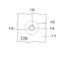
- FIG. 3 is a partial bottom view of the button mounting member of FIG.
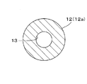
- FIG. 4 is a horizontal sectional view taken along the line AA in FIG.
- FIG. 5 is a horizontal sectional view taken along line BB in FIG.
- FIG. 6 is a cross-sectional explanatory view schematically showing an arrangement state of a punch, a female snap, a dough, a button attaching member, a lower die, and the like when the button is attached to the dough using the button attaching member of FIG.
- FIG. 1 is a perspective view partially showing a button attachment member according to an embodiment of the present invention.
- FIG. 2 is a longitudinal sectional view of the button mounting member of FIG.
- FIG. 3 is a partial bottom view of the button mounting member of FIG.
- FIG. 4 is a horizontal sectional view taken along the line
- FIG. 7 is a cross-sectional explanatory view schematically showing a state where the post portion of the button attachment member passes through the cloth and then passes through the attachment opening of the female snap.
- FIG. 8 is an explanatory cross-sectional view schematically showing a state in which the post tip portion of the button mounting member is crimped with a punch.
- FIG. 9 is a cross-sectional explanatory view substantially similar to FIG. 8 showing a state in which a male snap is fixed to the fabric with a button mounting member as another example of the button.
- FIG. 10 is a longitudinal sectional view of a button mounting member according to another embodiment of the present invention.
- FIG. 11 is a longitudinal sectional view of a button mounting member according to still another embodiment of the present invention.
- FIG. 12 is a longitudinal sectional view of a button mounting member according to a further embodiment of the present invention.
- FIG. 13 is a cross-sectional explanatory view schematically showing a state in which the post end portion is crimped with a punch when the female snap is attached to the fabric using the button attaching member of FIG.
- FIG. 14 is a partial cross-sectional explanatory view schematically showing a state in which the lower end opening of the button mounting member of FIG. 12 is closed by a lower punch.
- FIG. 1 is a perspective view showing a button attachment member 10 according to an embodiment of the present invention in a partial cross section
- FIG. 2 is a longitudinal sectional view of the button attachment member 10.
- the button mounting member 10 is a molded product made of a synthetic resin, and has a disk-shaped base portion 11 and a horizontal cross-section that protrudes upward (upper and lower are based on FIG. 2) concentrically with the base portion 11 from the base portion 11.
- the base portion 11 includes a front surface 11a facing upward and a back surface 11b facing downward.
- the back surface 11b is a curved surface that is slightly convex downward.
- the front surface 11a is substantially parallel to the rear surface 11b on the inner side in the radial direction of the outer surface 11a ′ and the annular outer surface 11a ′ along a horizontal plane (hereinafter also simply referred to as “horizontal”) perpendicular to the axis of the post portion 12.
- the post portion 12 rises from the front inner surface 11a ′′ of the base portion 11 and has a post base end portion 12a having a substantially constant outer diameter and an upper side from the upper end of the post base end portion 12a. And a post front end portion 12b whose outer diameter is gradually reduced and tapered.
- a tip 12c of the post tip 12b (that is, a tip of the post 12) is pointed so as to easily penetrate the fabric 1 (see FIG. 4 and the like).
- the ratio of the length along the axial direction of the post base end portion 12a and the post front end portion 12b is about 2 to 1, and the axial length of the post base end portion 12a in this case is the front inner side surface 11a of the base portion 11. ”(The lowest point adjacent to the post base end portion 12a) to the upper end of the post base end portion 12a.
- the post portion 12 has a cavity 13 therein.
- the cavity 13 is a space with a circular cross section that is concentric with the post portion 12 and extends in the axial direction (vertical direction).
- the lower end of the cavity 13 is opened as a circular lower end opening 14 on the back surface 11b of the base portion 11, and extends through the base portion 11 in the post base end portion 12a upward in the axial direction.
- the upper end of the cavity 13 is closed at an axial level slightly exceeding the upper end of the post base end portion 12a (the lower end of the post front end portion 12b), and is an upper end surface that is a circular closed end along the horizontal (hereinafter referred to as “cavity upper end surface”). (Also called) 15.
- FIG. 3 is a partial bottom view of the button mounting member 10, and shows a lower end opening 14 that appears on the back surface 11 b of the base portion 11 and a cavity upper end surface 15 that can be seen inside the lower end opening 14.
- the post part 12 is divided into a hollow part in which the cavity 13 exists in the axial direction and a solid part 16 in which the post part 12 does not exist.
- the cavity 13 exists in the entire axial direction of the post proximal end portion 12a, but hardly exists (exists slightly) in the post distal end portion 12b.
- the axial length of the solid portion 16 is about 1/3 of the axial length of the post portion 12 (the length from the front inner side surface 11a ′′ to the tip end 12c of the base portion 11).
- Fig. 3 is a horizontal sectional view taken along lines AA and BB in Fig. 2. Since the cavity 13 is reduced in diameter upward as described above, the post proximal end portion having the same outer diameter in Figs. 12a, the diameter of the cavity 13 is smaller at the post base end portion 12a than at Fig. 5.
- the diameter ratio between the post 12 and the cavity 13 is any one including the cross-sections of Figs.
- the axial position is about 3 to 1.
- FIG. 6 shows the female snap 20, the fabric 1, the button mounting member 10, the punch 30 used in this mounting process, and the lower part when the female snap 20, which is an example of a button, is attached to the fabric 1 using the button mounting member 10.
- FIG. 6 is a cross-sectional explanatory view schematically showing an arrangement state in the vertical direction with respect to the die 40.
- the punch 30 is a part of an upper die (not shown), and the upper die is also provided with a button holding portion for holding the female snap 20 when attached to the fabric 1.
- the female snap 20 is a molded product made of synthetic resin, and includes a disc-shaped bottom portion 21, a cylindrical side portion 22 extending upward from a radially outer end of the bottom portion 21, and a side portion above and below the bottom portion 21.
- the lower die 40 has a recess 42 on its upper surface 41 that matches the base portion 11 of the button mounting member 10. The button attachment member 10 is placed in the recess 42 of the lower die 40 below the horizontally disposed fabric 1.
- the post portion 12 of the button mounting member 10 penetrates the cloth 1 upward as shown in FIG. 25 and protrudes above the bottom 21 of the female snap 20.
- the punch 30 is lowered from this state, as shown in FIG. 8, the post leading end portion 12 b, which is the solid portion 16 of the post portion 12, is crushed in the axial direction by the punch 30 on the bottom portion 21 of the female snap 20. It is crimped to expand in the direction.
- the post tip after deformation is indicated by reference numeral 12b '.
- the female snap 20 is fixed to the fabric 1.
- the female snap 20 is exemplified as an example of the button to be attached to the cloth 1 by the button attaching member 10, but the present invention is not limited thereto, and as shown in FIG. 9, the male snap 50 is attached to the cloth 1 by the button attaching member 10. Can be attached to.
- reference numeral 51 is an engagement protrusion of the male snap 50
- reference numeral 52 is an opening for mounting the male snap 50.
- FIG. 10 is a longitudinal cross-sectional explanatory view of a button mounting member 60 according to another embodiment of the present invention.
- the button attachment member 60 has the same form as the button attachment member 10 described above except for the form of the cavity 63, and includes a disk-like base portion 61 and a post portion 62 protruding from the base portion 61.
- the post portion 62 has a post base end portion 62a having a substantially constant outer diameter, and a post front end portion 62b whose outer diameter gradually decreases from the upper end of the post base end portion 62a to the tip end 62c.
- the cavity 63 extends from the back surface of the base portion 61 through the base portion 61 and extends upward in the post base end portion 62a in the axial direction, exceeds the upper end level of the post base end portion 62a, and is formed inside the post front end portion 62b.
- the level reaches about 2/3 of the axial length of the tip 62b.
- the diameter of the cavity 63 gradually decreases from the lower end opening 64 to the upper end surface 65.
- the axial length of the cavity 63 is 4/5 of the axial length of the post portion 62 (height from the surface of the base portion 61 of the post portion 62), and the cavity 63 does not exist.
- the axial length of the real part 66 is 1/5 of the axial length of the post part 62.
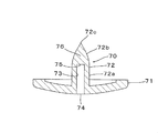
- FIG. 11 is a longitudinal cross-sectional explanatory view of a button mounting member 70 according to still another embodiment of the present invention.
- the button attachment member 70 has the same form as the above-described button attachment member 10 except for the form of the cavity 73, and includes a disk-like base portion 71 and a post portion 72 protruding from the base portion 71.
- the post portion 72 has a post base end portion 72a having a substantially constant outer diameter, and a post front end portion 72b whose outer diameter gradually decreases from the upper end of the post base end portion 72a to the tip end 72c.
- the cavity 73 has a constant diameter and extends from the lower end opening 74 to the upper end surface 75 at the upper end level of the post base end portion 72a. Therefore, the ratio of the lengths of the cavity 73 and the solid portion 76 along the axial direction is about 2 to 1 as in the case of the button mounting member 10.
- FIG. 12 is a longitudinal cross-sectional explanatory view of a button mounting member 80 according to a further embodiment of the present invention.
- the button attachment member 80 has an annular convex portion 87 that protrudes downward around the lower end opening 84 of the cavity 83 on the back surface of the base portion 81.
- the button attachment member 80 has substantially the same form as the above-described button attachment member 10 except that the annular protrusion 87 is provided, and the post portion 82 has a post base end portion 82a having a substantially constant outer diameter. And a post distal end portion 82b whose outer diameter gradually decreases from the upper end of the post proximal end portion 82a to the distal end 82c.
- FIG. 12 is a longitudinal cross-sectional explanatory view of a button mounting member 80 according to a further embodiment of the present invention.
- the button attachment member 80 has an annular convex portion 87 that protrudes downward around the lower end opening 84 of the cavity 83 on the back surface of
- reference numeral 85 indicates an upper end surface of the cavity 83
- reference numeral 86 indicates a solid part.
- the annular protrusion 87 attaches the female snap 20 to the cloth 1 (the female snap and the cloth are the same as those shown in FIG. At this time, the lower end opening 84 is closed.
- the post tip 82b of the button attachment member 80 is the same as the punch 30 (the same reference numeral is assigned to the punch 30 as shown in FIG. 8 and the like).
- the post end after deformation is indicated by reference numeral 82 b ′
- the button mounting member 80 is placed in the recess 92 on the upper surface 91 of the lower die 90.
- the lower die 90 has a cylindrical shape, and includes a central passage 93 extending along the axis thereof and a lower punch 94 that can move up and down the central passage 93.
- the lower punch 94 is raised at the same time as or immediately after the punch 30 crimps the post leading end portion 82b, and crushes the annular convex portion 87 so as to be substantially flush with the back surface of the base portion 81 (see FIG. 14). ).
- the deformed annular convex portion is represented by 87 '. Thereby, the lower end opening 84 of the cavity 83 is closed.
- the button mounting members 10, 60, 70, 80 since the thickness of the post portions 12, 62, 72, 82 is reduced by providing the cavities 13, 63, 73, 83, the button mounting members 10, 60 , 70, 80 are almost completely voided in the post portions 12, 62, 72, 82 even when injection molded.
- the solid portions 16, 66, 76, 86 of the post portions 12, 62, 72, 82 can secure a necessary amount of meat during caulking.
Landscapes
- Slide Fasteners, Snap Fasteners, And Hook Fasteners (AREA)
Abstract
Description
10、60、70、80 ボタン取付部材
11、61、71、81 ベース部
12、62、72、82 ポスト部
12a、62a、72a、82a ポスト基端部
12b、62b、72b、82b ポスト先端部
12c、62c、72c、82c 先端
13、63、73、83 空洞
14、64、74、84 (空洞の)下端開口
15、65、75、85 (空洞の)上端面
16、66、76、86 中実部
20 雌スナップ
25、52 取付用開口
50 雄スナップ
87 環状凸部
Claims (6)
- 取付用開口(25、52)を有するボタン(20、50)を生地(1)に取り付ける際に用いる合成樹脂製のボタン取付部材(10、60、70、80)であって、
板状のベース部(11、61、71、81)と、ベース部(11、61、71、81)からベース部(11、61、71、81)の表面(11a)側に突出するポスト部(12、62、72、82)にして、ボタン(20、50)の生地(1)への取り付け時に生地(1)を貫通し次いでボタン(20、50)の取付用開口(25、52)を通った後、変形させられるポスト部(12、62、72、82)とを備え、
ポスト部(12、62、72、82)は、ベース部(11、61、71、81)の裏面(11b)の開口(14、64、74、84)からポスト部(12、62、72、82)の先端(12c、62c、72c、82c)側の閉端(15、65、75、85)までポスト部(12、62、72、82)と同心状に延びる空洞(13、63、73、83)と、空洞(13、63、73、83)の閉端(15、65、75、85)とポスト部(12、62、72、82)の先端(12c、62c、72c、82c)との間の中実部(16、66、76、86)とを含むボタン取付部材。 - 前記中実部(16、66、76、86)のポスト部(12、62、72、82)の長手方向における長さは、ベース部(11、61、71、81)の表面(11a”)からポスト部(12、62、72、82)の先端(12c、62c、72c、82c)までのポスト部(12、62、72、82)の長さの1/5以上である請求項1のボタン取付部材。
- 前記空洞(13、63、83)の径は開口(14、64、84)から閉端(15、65、85)へと次第に縮小する請求項1又は2のボタン取付部材。
- 前記ポスト部(12、62、82)はベース部(11、61、81)から立ち上がる外径が一定のポスト基端部(12a、62a、82a)と、ポスト基端部(12a、62a、82a)の上端から先端(12c、62c、82c)へと外径が次第に縮小するポスト先端部(12b、62b、82b)とを有し、ポスト基端部(12a、62a、82a)が前記空洞(13、63、83)を有する請求項3のボタン取付部材。
- 前記ベース部(81)の裏面における開口(84)の周囲に、ボタン(20、50)の生地(1)への取り付け時に前記開口(84)を閉鎖加工するための環状凸部(87)を有する請求項1~4のいずれか一つのボタン取付部材。
- 取付用開口(25、52)を有するボタン(20、50)と、ボタン(20、50)を生地(1)に取り付ける際に用いる合成樹脂製のボタン取付部材(10、60、70、80)とからなるボタン構成体であって、前記ボタン取付部材(10、60、70、80)は、
板状のベース部(11、61、71、81)と、ベース部(11、61、71、81)からベース部(11、61、71、81)の表面(11a)側に突出するポスト部(12、62、72、82)にして、ボタン(20、50)の生地(1)への取り付け時に生地(1)を貫通し次いでボタン(20、50)の取付用開口(25、52)を通った後、変形させられるポスト部(12、62、72、82)とを備え、
ポスト部(12、62、72、82)は、ベース部(11、61、71、81)の裏面(11b)の開口(14、64、74、84)からポスト部(12、62、72、82)の先端(12c、62c、72c、82c)側の閉端(15、65、75、85)までポスト部(12、62、72、82)と同心状に延びる空洞(13、63、73、83)と、空洞(13、63、73、83)の閉端(15、65、75、85)とポスト部(12、62、72、82)の先端(12c、62c、72c、82c)との間の中実部(16、66、76、86)とを含むボタン構成体。
Priority Applications (6)
| Application Number | Priority Date | Filing Date | Title |
|---|---|---|---|
| US13/812,169 US9060572B2 (en) | 2010-07-26 | 2010-07-26 | Button fixing member and button structure |
| JP2012526226A JP5596151B2 (ja) | 2010-07-26 | 2010-07-26 | ボタン取付部材及びボタン構成体 |
| DE112010005770.2T DE112010005770B4 (de) | 2010-07-26 | 2010-07-26 | Knopfbefestigungsteil und Knopfanordnung |
| CN201080069273.1A CN103118560B (zh) | 2010-07-26 | 2010-07-26 | 钮扣安装构件和钮扣结构体 |
| PCT/JP2010/062555 WO2012014274A1 (ja) | 2010-07-26 | 2010-07-26 | ボタン取付部材及びボタン構成体 |
| TW100111354A TWI513418B (zh) | 2010-07-26 | 2011-03-31 | Button mounting member and button structure |
Applications Claiming Priority (1)
| Application Number | Priority Date | Filing Date | Title |
|---|---|---|---|
| PCT/JP2010/062555 WO2012014274A1 (ja) | 2010-07-26 | 2010-07-26 | ボタン取付部材及びボタン構成体 |
Publications (1)
| Publication Number | Publication Date |
|---|---|
| WO2012014274A1 true WO2012014274A1 (ja) | 2012-02-02 |
Family
ID=45529522
Family Applications (1)
| Application Number | Title | Priority Date | Filing Date |
|---|---|---|---|
| PCT/JP2010/062555 Ceased WO2012014274A1 (ja) | 2010-07-26 | 2010-07-26 | ボタン取付部材及びボタン構成体 |
Country Status (6)
| Country | Link |
|---|---|
| US (1) | US9060572B2 (ja) |
| JP (1) | JP5596151B2 (ja) |
| CN (1) | CN103118560B (ja) |
| DE (1) | DE112010005770B4 (ja) |
| TW (1) | TWI513418B (ja) |
| WO (1) | WO2012014274A1 (ja) |
Cited By (4)
| Publication number | Priority date | Publication date | Assignee | Title |
|---|---|---|---|---|
| CN102657401A (zh) * | 2012-05-28 | 2012-09-12 | 李锦全 | 一种金属钮扣或衣物撞钉的装配方法 |
| JP2015023983A (ja) * | 2013-07-26 | 2015-02-05 | 武田精機株式会社 | スナップボタン用の合成樹脂製リベット部材 |
| JP2016079520A (ja) * | 2014-10-15 | 2016-05-16 | 香港多耐福有限公司Duraflex Hong Kong Limited | 樹脂リベット |
| KR101731944B1 (ko) | 2015-07-21 | 2017-05-02 | 유충한 | 타포린용 아일렛 |
Families Citing this family (12)
| Publication number | Priority date | Publication date | Assignee | Title |
|---|---|---|---|---|
| JP6090932B2 (ja) * | 2013-11-29 | 2017-03-08 | 武田 精 | ジーンズ用の合成樹脂製ボタン |
| WO2016038666A1 (ja) * | 2014-09-08 | 2016-03-17 | Ykk株式会社 | リベット |
| JP6415724B2 (ja) * | 2015-07-22 | 2018-10-31 | Ykk株式会社 | リベット |
| CN105795616B (zh) * | 2016-05-25 | 2018-11-23 | 李棠华 | 可提高安装效率的四合扣 |
| CN105901841A (zh) * | 2016-07-06 | 2016-08-31 | 太仓市哲泰天产品设计有限公司 | 一种用于布料的二合扣 |
| JP6847725B2 (ja) * | 2017-03-23 | 2021-03-24 | Ykk株式会社 | 雌型ボタン、及び雌型ボタンと雄型ボタンの組み合わせ品 |
| EP3639690B1 (en) * | 2017-06-12 | 2021-08-18 | Ykk Corporation | Button |
| US10066658B1 (en) * | 2017-08-01 | 2018-09-04 | Ykk Corporation Of America | Non-rotatable fastener assembly and associated methods |
| US11116264B2 (en) | 2018-02-14 | 2021-09-14 | Gina Rae Adams | Magnetic button adapter system and method for manufacturing |
| US10813417B2 (en) | 2019-01-25 | 2020-10-27 | Love Your Melon Inc. | Snap fastener receiver techniques |
| CN110638153B (zh) * | 2019-08-30 | 2022-06-03 | 宏基钮扣(石狮)有限公司 | 一种高精度钮扣 |
| WO2026039584A1 (en) * | 2024-08-14 | 2026-02-19 | Faherty Brand Llc | Low profile shank fastener |
Citations (8)
| Publication number | Priority date | Publication date | Assignee | Title |
|---|---|---|---|---|
| US3349451A (en) * | 1963-07-10 | 1967-10-31 | Kanegafuchi Spinning Co Ltd | Plastic gripper button |
| JPS5065344A (ja) * | 1973-10-11 | 1975-06-03 | ||
| JPS6083406U (ja) * | 1983-11-16 | 1985-06-08 | 日本ノーシヨン工業株式会社 | 釦等用鋲 |
| JPS63167127U (ja) * | 1987-04-22 | 1988-10-31 | ||
| JPH07289311A (ja) * | 1994-04-20 | 1995-11-07 | Kiyoshi Takeda | スナップファスナー |
| JPH08299027A (ja) * | 1995-05-12 | 1996-11-19 | Kiyoshi Takeda | スナップファスナー |
| JPH1033210A (ja) * | 1996-07-29 | 1998-02-10 | Morito Kk | テープ付きスナップ |
| JPH1132815A (ja) * | 1997-07-17 | 1999-02-09 | Ykk Corp | スナップボタンおよびその取付方法 |
Family Cites Families (7)
| Publication number | Priority date | Publication date | Assignee | Title |
|---|---|---|---|---|
| US3195201A (en) * | 1963-04-17 | 1965-07-20 | Scovill Manufacturing Co | Ornamental snap fastener assembly |
| JPS53100045A (en) * | 1977-02-10 | 1978-09-01 | Tomiya Kk | Hook |
| JPS58164512U (ja) * | 1981-12-07 | 1983-11-01 | 日本ノ−シヨン工業株式会社 | 被服用スナツプ |
| JPS5986111U (ja) * | 1982-12-01 | 1984-06-11 | 日本ノ−シヨン工業株式会社 | スナツプ釦の雌体 |
| JPH038086Y2 (ja) * | 1986-03-13 | 1991-02-28 | ||
| JP2856157B2 (ja) | 1996-07-16 | 1999-02-10 | 日本電気株式会社 | 半導体装置の製造方法 |
| JP2001178505A (ja) * | 1999-12-24 | 2001-07-03 | Ykk Corp | ボタン用タック |
-
2010
- 2010-07-26 US US13/812,169 patent/US9060572B2/en active Active
- 2010-07-26 CN CN201080069273.1A patent/CN103118560B/zh active Active
- 2010-07-26 WO PCT/JP2010/062555 patent/WO2012014274A1/ja not_active Ceased
- 2010-07-26 DE DE112010005770.2T patent/DE112010005770B4/de active Active
- 2010-07-26 JP JP2012526226A patent/JP5596151B2/ja active Active
-
2011
- 2011-03-31 TW TW100111354A patent/TWI513418B/zh active
Patent Citations (8)
| Publication number | Priority date | Publication date | Assignee | Title |
|---|---|---|---|---|
| US3349451A (en) * | 1963-07-10 | 1967-10-31 | Kanegafuchi Spinning Co Ltd | Plastic gripper button |
| JPS5065344A (ja) * | 1973-10-11 | 1975-06-03 | ||
| JPS6083406U (ja) * | 1983-11-16 | 1985-06-08 | 日本ノーシヨン工業株式会社 | 釦等用鋲 |
| JPS63167127U (ja) * | 1987-04-22 | 1988-10-31 | ||
| JPH07289311A (ja) * | 1994-04-20 | 1995-11-07 | Kiyoshi Takeda | スナップファスナー |
| JPH08299027A (ja) * | 1995-05-12 | 1996-11-19 | Kiyoshi Takeda | スナップファスナー |
| JPH1033210A (ja) * | 1996-07-29 | 1998-02-10 | Morito Kk | テープ付きスナップ |
| JPH1132815A (ja) * | 1997-07-17 | 1999-02-09 | Ykk Corp | スナップボタンおよびその取付方法 |
Cited By (5)
| Publication number | Priority date | Publication date | Assignee | Title |
|---|---|---|---|---|
| CN102657401A (zh) * | 2012-05-28 | 2012-09-12 | 李锦全 | 一种金属钮扣或衣物撞钉的装配方法 |
| CN102657401B (zh) * | 2012-05-28 | 2014-05-07 | 李锦全 | 一种金属钮扣或衣物撞钉的装配方法 |
| JP2015023983A (ja) * | 2013-07-26 | 2015-02-05 | 武田精機株式会社 | スナップボタン用の合成樹脂製リベット部材 |
| JP2016079520A (ja) * | 2014-10-15 | 2016-05-16 | 香港多耐福有限公司Duraflex Hong Kong Limited | 樹脂リベット |
| KR101731944B1 (ko) | 2015-07-21 | 2017-05-02 | 유충한 | 타포린용 아일렛 |
Also Published As
| Publication number | Publication date |
|---|---|
| CN103118560A (zh) | 2013-05-22 |
| CN103118560B (zh) | 2015-06-24 |
| TW201204278A (en) | 2012-02-01 |
| US9060572B2 (en) | 2015-06-23 |
| US20130117972A1 (en) | 2013-05-16 |
| DE112010005770T5 (de) | 2013-05-08 |
| TWI513418B (zh) | 2015-12-21 |
| DE112010005770B4 (de) | 2024-04-18 |
| JP5596151B2 (ja) | 2014-09-24 |
| JPWO2012014274A1 (ja) | 2013-09-09 |
Similar Documents
| Publication | Publication Date | Title |
|---|---|---|
| JP5596151B2 (ja) | ボタン取付部材及びボタン構成体 | |
| US7752718B2 (en) | Snap fastener | |
| CN105363219B (zh) | 拼装玩具元件和套件 | |
| JP2016504226A (ja) | 締結要素を射出成形するための方法及び締結要素 | |
| CN113491375A (zh) | 带有可拆卸螺钉的扣及可拆卸螺钉的安装方法 | |
| US20160362168A1 (en) | Retention of an electro-optic window assembly | |
| US10219588B2 (en) | Belt lock housing | |
| US20140054824A1 (en) | Insert molding method and article formed by same | |
| US20150291012A1 (en) | Two piece housing assembly with elongated attachment and method for making the same | |
| KR101418562B1 (ko) | 이중사출형 도마 | |
| JP5691287B2 (ja) | 発泡成形部材、その取付用クリップ、発泡成形部材の製造方法並びに発泡成形部材の取付構造 | |
| CN207519739U (zh) | 一种装饰钮 | |
| KR20190113117A (ko) | 스냅파스너의 제조방법 및 이에 따라 제조된 스냅파스너 | |
| CN203016000U (zh) | 一种装饰钮 | |
| CN207544493U (zh) | 一种四合扣 | |
| JP2009234072A (ja) | 表皮付部材の表皮材、表皮付部材およびその製造方法 | |
| US20080136057A1 (en) | Method for producing sucker elements, sucker element produced with the method, and article with sucker | |
| KR101683099B1 (ko) | 고리가 일체로 구비되는 악세서리 | |
| CN214179398U (zh) | 一种工字钮扣 | |
| CN224069917U (zh) | 一种化妆品粉盒 | |
| KR101966002B1 (ko) | 양변기 하부 테두리 마감부재 | |
| KR200456306Y1 (ko) | 플라스틱 삽 본체 | |
| CN2928458Y (zh) | 鞋钉的模具装置 | |
| KR102181973B1 (ko) | 커버링 쉘프 케이블 유닛 | |
| CN202728033U (zh) | 汽车脚踏垫挂架结构 |
Legal Events
| Date | Code | Title | Description |
|---|---|---|---|
| WWE | Wipo information: entry into national phase |
Ref document number: 201080069273.1 Country of ref document: CN |
|
| 121 | Ep: the epo has been informed by wipo that ep was designated in this application |
Ref document number: 10855285 Country of ref document: EP Kind code of ref document: A1 |
|
| WWE | Wipo information: entry into national phase |
Ref document number: 2012526226 Country of ref document: JP |
|
| WWE | Wipo information: entry into national phase |
Ref document number: 13812169 Country of ref document: US |
|
| WWE | Wipo information: entry into national phase |
Ref document number: 112010005770 Country of ref document: DE Ref document number: 1120100057702 Country of ref document: DE |
|
| 122 | Ep: pct application non-entry in european phase |
Ref document number: 10855285 Country of ref document: EP Kind code of ref document: A1 |