WO2012008289A1 - 光情報記録媒体および光情報記録方法 - Google Patents
光情報記録媒体および光情報記録方法 Download PDFInfo
- Publication number
- WO2012008289A1 WO2012008289A1 PCT/JP2011/064673 JP2011064673W WO2012008289A1 WO 2012008289 A1 WO2012008289 A1 WO 2012008289A1 JP 2011064673 W JP2011064673 W JP 2011064673W WO 2012008289 A1 WO2012008289 A1 WO 2012008289A1
- Authority
- WO
- WIPO (PCT)
- Prior art keywords
- recording
- optical information
- layer
- recording layer
- compound
- Prior art date
- Legal status (The legal status is an assumption and is not a legal conclusion. Google has not performed a legal analysis and makes no representation as to the accuracy of the status listed.)
- Ceased
Links
Images

Classifications
-
- G—PHYSICS
- G11—INFORMATION STORAGE
- G11B—INFORMATION STORAGE BASED ON RELATIVE MOVEMENT BETWEEN RECORD CARRIER AND TRANSDUCER
- G11B7/00—Recording or reproducing by optical means, e.g. recording using a thermal beam of optical radiation by modifying optical properties or the physical structure, reproducing using an optical beam at lower power by sensing optical properties; Record carriers therefor
- G11B7/24—Record carriers characterised by shape, structure or physical properties, or by the selection of the material
- G11B7/2403—Layers; Shape, structure or physical properties thereof
- G11B7/24035—Recording layers
-
- B—PERFORMING OPERATIONS; TRANSPORTING
- B82—NANOTECHNOLOGY
- B82Y—SPECIFIC USES OR APPLICATIONS OF NANOSTRUCTURES; MEASUREMENT OR ANALYSIS OF NANOSTRUCTURES; MANUFACTURE OR TREATMENT OF NANOSTRUCTURES
- B82Y10/00—Nanotechnology for information processing, storage or transmission, e.g. quantum computing or single electron logic
-
- G—PHYSICS
- G11—INFORMATION STORAGE
- G11B—INFORMATION STORAGE BASED ON RELATIVE MOVEMENT BETWEEN RECORD CARRIER AND TRANSDUCER
- G11B7/00—Recording or reproducing by optical means, e.g. recording using a thermal beam of optical radiation by modifying optical properties or the physical structure, reproducing using an optical beam at lower power by sensing optical properties; Record carriers therefor
- G11B7/004—Recording, reproducing or erasing methods; Read, write or erase circuits therefor
- G11B7/0045—Recording
- G11B7/00451—Recording involving ablation of the recording layer
-
- G—PHYSICS
- G11—INFORMATION STORAGE
- G11B—INFORMATION STORAGE BASED ON RELATIVE MOVEMENT BETWEEN RECORD CARRIER AND TRANSDUCER
- G11B7/00—Recording or reproducing by optical means, e.g. recording using a thermal beam of optical radiation by modifying optical properties or the physical structure, reproducing using an optical beam at lower power by sensing optical properties; Record carriers therefor
- G11B7/004—Recording, reproducing or erasing methods; Read, write or erase circuits therefor
- G11B7/0045—Recording
- G11B7/00452—Recording involving bubble or bump forming
-
- G—PHYSICS
- G11—INFORMATION STORAGE
- G11B—INFORMATION STORAGE BASED ON RELATIVE MOVEMENT BETWEEN RECORD CARRIER AND TRANSDUCER
- G11B7/00—Recording or reproducing by optical means, e.g. recording using a thermal beam of optical radiation by modifying optical properties or the physical structure, reproducing using an optical beam at lower power by sensing optical properties; Record carriers therefor
- G11B7/004—Recording, reproducing or erasing methods; Read, write or erase circuits therefor
- G11B7/0055—Erasing
-
- G—PHYSICS
- G11—INFORMATION STORAGE
- G11B—INFORMATION STORAGE BASED ON RELATIVE MOVEMENT BETWEEN RECORD CARRIER AND TRANSDUCER
- G11B7/00—Recording or reproducing by optical means, e.g. recording using a thermal beam of optical radiation by modifying optical properties or the physical structure, reproducing using an optical beam at lower power by sensing optical properties; Record carriers therefor
- G11B7/24—Record carriers characterised by shape, structure or physical properties, or by the selection of the material
- G11B7/241—Record carriers characterised by shape, structure or physical properties, or by the selection of the material characterised by the selection of the material
- G11B7/242—Record carriers characterised by shape, structure or physical properties, or by the selection of the material characterised by the selection of the material of recording layers
- G11B7/244—Record carriers characterised by shape, structure or physical properties, or by the selection of the material characterised by the selection of the material of recording layers comprising organic materials only
- G11B7/246—Record carriers characterised by shape, structure or physical properties, or by the selection of the material characterised by the selection of the material of recording layers comprising organic materials only containing dyes
-
- G—PHYSICS
- G11—INFORMATION STORAGE
- G11B—INFORMATION STORAGE BASED ON RELATIVE MOVEMENT BETWEEN RECORD CARRIER AND TRANSDUCER
- G11B7/00—Recording or reproducing by optical means, e.g. recording using a thermal beam of optical radiation by modifying optical properties or the physical structure, reproducing using an optical beam at lower power by sensing optical properties; Record carriers therefor
- G11B7/24—Record carriers characterised by shape, structure or physical properties, or by the selection of the material
- G11B7/241—Record carriers characterised by shape, structure or physical properties, or by the selection of the material characterised by the selection of the material
- G11B7/242—Record carriers characterised by shape, structure or physical properties, or by the selection of the material characterised by the selection of the material of recording layers
- G11B7/244—Record carriers characterised by shape, structure or physical properties, or by the selection of the material characterised by the selection of the material of recording layers comprising organic materials only
- G11B7/245—Record carriers characterised by shape, structure or physical properties, or by the selection of the material characterised by the selection of the material of recording layers comprising organic materials only containing a polymeric component
-
- G—PHYSICS
- G11—INFORMATION STORAGE
- G11B—INFORMATION STORAGE BASED ON RELATIVE MOVEMENT BETWEEN RECORD CARRIER AND TRANSDUCER
- G11B7/00—Recording or reproducing by optical means, e.g. recording using a thermal beam of optical radiation by modifying optical properties or the physical structure, reproducing using an optical beam at lower power by sensing optical properties; Record carriers therefor
- G11B7/24—Record carriers characterised by shape, structure or physical properties, or by the selection of the material
- G11B7/241—Record carriers characterised by shape, structure or physical properties, or by the selection of the material characterised by the selection of the material
- G11B7/242—Record carriers characterised by shape, structure or physical properties, or by the selection of the material characterised by the selection of the material of recording layers
- G11B7/244—Record carriers characterised by shape, structure or physical properties, or by the selection of the material characterised by the selection of the material of recording layers comprising organic materials only
- G11B7/246—Record carriers characterised by shape, structure or physical properties, or by the selection of the material characterised by the selection of the material of recording layers comprising organic materials only containing dyes
- G11B7/2467—Record carriers characterised by shape, structure or physical properties, or by the selection of the material characterised by the selection of the material of recording layers comprising organic materials only containing dyes azo-dyes
-
- G—PHYSICS
- G11—INFORMATION STORAGE
- G11B—INFORMATION STORAGE BASED ON RELATIVE MOVEMENT BETWEEN RECORD CARRIER AND TRANSDUCER
- G11B7/00—Recording or reproducing by optical means, e.g. recording using a thermal beam of optical radiation by modifying optical properties or the physical structure, reproducing using an optical beam at lower power by sensing optical properties; Record carriers therefor
- G11B7/24—Record carriers characterised by shape, structure or physical properties, or by the selection of the material
- G11B7/241—Record carriers characterised by shape, structure or physical properties, or by the selection of the material characterised by the selection of the material
- G11B7/242—Record carriers characterised by shape, structure or physical properties, or by the selection of the material characterised by the selection of the material of recording layers
- G11B7/244—Record carriers characterised by shape, structure or physical properties, or by the selection of the material characterised by the selection of the material of recording layers comprising organic materials only
- G11B7/249—Record carriers characterised by shape, structure or physical properties, or by the selection of the material characterised by the selection of the material of recording layers comprising organic materials only containing organometallic compounds
- G11B7/2495—Record carriers characterised by shape, structure or physical properties, or by the selection of the material characterised by the selection of the material of recording layers comprising organic materials only containing organometallic compounds as anions
-
- Y—GENERAL TAGGING OF NEW TECHNOLOGICAL DEVELOPMENTS; GENERAL TAGGING OF CROSS-SECTIONAL TECHNOLOGIES SPANNING OVER SEVERAL SECTIONS OF THE IPC; TECHNICAL SUBJECTS COVERED BY FORMER USPC CROSS-REFERENCE ART COLLECTIONS [XRACs] AND DIGESTS
- Y10—TECHNICAL SUBJECTS COVERED BY FORMER USPC
- Y10T—TECHNICAL SUBJECTS COVERED BY FORMER US CLASSIFICATION
- Y10T428/00—Stock material or miscellaneous articles
- Y10T428/26—Web or sheet containing structurally defined element or component, the element or component having a specified physical dimension
- Y10T428/263—Coating layer not in excess of 5 mils thick or equivalent
- Y10T428/264—Up to 3 mils
- Y10T428/265—1 mil or less
-
- Y—GENERAL TAGGING OF NEW TECHNOLOGICAL DEVELOPMENTS; GENERAL TAGGING OF CROSS-SECTIONAL TECHNOLOGIES SPANNING OVER SEVERAL SECTIONS OF THE IPC; TECHNICAL SUBJECTS COVERED BY FORMER USPC CROSS-REFERENCE ART COLLECTIONS [XRACs] AND DIGESTS
- Y10—TECHNICAL SUBJECTS COVERED BY FORMER USPC
- Y10T—TECHNICAL SUBJECTS COVERED BY FORMER US CLASSIFICATION
- Y10T428/00—Stock material or miscellaneous articles
- Y10T428/31504—Composite [nonstructural laminate]
Definitions
- the present invention relates to an optical information recording medium and an optical information recording method in which information is recorded by forming bubbles by light irradiation.
- the recording layer is multilayered.
- a write-once DVD and a Blu-ray (registered trademark) disk are known.
- these use a one-photon absorption material for the recording layer, and the selectivity of the layer that reacts only with a specific recording layer at the time of recording is low, and recording is performed on the back layer as viewed from the recording light irradiation side.
- recording light is absorbed in the recording layer on the front side, there is a problem that the loss of recording light is large.
- the multiphoton absorption reaction is a reaction that absorbs photons when a plurality of (for example, two) photons are applied to the recording layer almost simultaneously.
- the two-photon absorption reaction light is absorbed in proportion to the square of the light intensity, so that it is possible to cause the reaction only near the focal point of the beam having a relatively high light intensity.
- the multiphoton absorption compound has a problem that the light (multiphoton) absorption efficiency is low and the recording sensitivity is low as compared with the one-photon absorption compound that is already widely used as a recording material for optical information recording media. There is. Such low recording sensitivity leads to a decrease in recording speed, which is undesirable.
- an object of the present invention is to improve recording sensitivity in an optical information recording medium using a multiphoton absorption reaction.
- an optical information recording medium of the present invention includes a recording layer having a multiphoton absorption compound and a one-photon absorption compound, and a support that supports the recording layer, and is based on the multiphoton absorption compound. Bubbles are generated along with absorption of multiphotons and absorption of one photon by the one-photon compound, and information is recorded by modulation depending on the presence or absence of the bubbles.
- both the multiphoton absorption compound and the one-photon absorption compound are contained in the recording layer. Therefore, in addition to the energy absorption by the multiphoton absorption reaction, the one-photon absorption reaction at the recording location. Absorption of energy occurs simultaneously. By absorbing these energies, bubbles can be generated, and information can be recorded by modulation based on the presence or absence of bubbles.
- the recording sensitivity can be improved as compared with the case where only the multiphoton absorption compound is used as the recording material in the recording layer. Thereby, the recording speed can be improved.
- the absorptance of the one-photon absorption compound can be reduced as compared with the case where only the one-photon absorption compound is used as the recording material in the recording layer, the optical information recording medium using only the one-photon absorption compound is used. In comparison, recording layer loss during recording and recording light loss due to one-photon absorption can be reduced.
- At least one of the multiphoton absorption compound and the one-photon absorption compound can be configured to be a foamable material that generates bubbles due to an increase in temperature due to light absorption.
- the recording layer includes a vaporization material that generates bubbles due to a temperature increase due to light absorption of the multiphoton absorption compound and the one-photon absorption compound, in addition to the multiphoton absorption compound and the one-photon absorption compound. It can also be.
- the recording layer preferably contains a polymer binder and can be erased by heating.
- a polymer binder By including the polymer binder, the fluidity of the polymer binder is improved by heating and the bubbles cannot be maintained, and information can be erased by disappearance.
- the size of the generated bubbles is in the range of 0.01 to 10 ⁇ m, and the recording layer has a thickness of 0.01 to 10 ⁇ m. It is desirable to be.
- the recording layer is provided in a plurality of layers, and the recording light irradiated when recording information and the reading light irradiated when reproducing information are recorded between the recording layers.
- the intermediate layer between the recording layers in this way, crosstalk between the recording layers can be prevented, and the intermediate layer substantially absorbs one-photon absorption and multi-photon absorption of recording light or reading light. Since there is no loss, the loss of recording light and reading light can be prevented, and the S / N ratio of recording and reproduction can be improved.
- the recording layer preferably has an absorption rate of one-photon absorption with respect to the recording light of 5% or less per layer.
- the present invention for solving the aforementioned problems is an optical information recording method for recording information on an optical information recording medium comprising a recording layer having a multiphoton absorbing compound and a one-photon absorbing compound, and a support for supporting the recording layer.
- a recording layer having a multiphoton absorbing compound and a one-photon absorbing compound
- a support for supporting the recording layer.
- the above-described optical information recording medium containing a polymer binder in the recording layer can erase information recorded once. That is, the method for erasing information recorded on the optical information recording medium described above is characterized in that the information recorded on the recording layer is erased by heating the recording layer.
- a method of irradiating a continuous wave laser so as to focus on the recording layer can be used.
- the specific recording layer can be heated by utilizing the heat generated by the light absorption of the dye contained in the recording layer (1-photon absorption).
- heating with a continuous wave laser information in a continuous area in the recording layer can be erased without unevenness.
- the information recorded in all the recording layers can be erased by heating the entire optical information recording medium.
- the entire information of the optical information recording medium can be easily erased and initialized.
- information can be easily deleted when the optical information recording medium is discarded.
- a multilayer optical recording medium 10 as an example of an optical information recording medium is provided with a large number of recording layers 12 and intermediate layers 13 on a base layer 11 as an example of a support. The opposite side is covered with a cover layer 14. A servo layer 15 for tracking is provided between the base layer 11 and the recording layer 12.
- the overall shape of the multilayer optical recording medium 10 is not particularly limited, and can be appropriately formed into a necessary shape such as a disk shape or a card shape.
- the base layer 11 serves as a support for the multilayer optical recording medium 10, and may be a relatively thick substrate of several hundred ⁇ m to several mm, or thinner (about 10 to 200 ⁇ m). It may be a film.
- the material of the base layer 11 is not particularly limited, but when information is recorded / reproduced by irradiating light from the base layer 11 side, light used for recording / reproducing information (recording light, readout light (information reproduction)
- a material that is sufficiently transmissive to the recording layer 12 sometimes abbreviated as “recording / reproducing light” and the reproducing light (including the signal generated by the irradiation of the reading light). It is desirable to use
- the recording layer 12 is a layer made of a recording material capable of recording information by light (including ultraviolet light and infrared light) such as laser light.
- the recording layer 12 includes, as a recording material, a multiphoton absorption compound that causes a multiphoton absorption reaction such as two-photon absorption or three-photon absorption when irradiated with light, and a one-photon absorption compound that causes a one-photon absorption reaction.
- the recording material Since the recording material generates bubbles by absorbing light, for example, a foamable material in which one or both of the multiphoton absorbing material and the one-photon absorbing material generate bubbles when the temperature rises can be used. .
- the generation principle of the bubbles at this time is not particularly limited.
- the multiphoton absorption material or the one-photon absorption material itself may be vaporized, or the multiphoton absorption material or the one-photon absorption material is decomposed due to a temperature rise. Bubbles may be generated during the decomposition.
- the recording material can include a multi-photon absorption compound and a vaporization material that generates bubbles due to temperature rise due to light absorption of the one-photon absorption compound, in addition to the multi-photon absorption material and the one-photon absorption material.
- the multiphoton absorbing material and the one-photon absorbing material may or may not have foaming properties.
- the size (diameter) of bubbles generated by irradiating the recording layer 12 with light is preferably 0.01 to 10 ⁇ m, more preferably 0.05 to 5 ⁇ m, and more preferably 0.1 to 2 ⁇ m. More desirable. That is, it is desirable to adjust the thickness of the recording layer 12 and the composition of the recording material so that bubbles of such a size are generated.
- the S / N ratio during reproduction can be sufficiently increased, and by setting the bubble size to 10 ⁇ m or less, the information recording density can be sufficiently increased.
- the multiphoton absorption compound is preferably one that causes a multiphoton absorption reaction at a wavelength of 650 nm or less
- the one-photon absorption compound is also preferably one that causes a one-photon absorption reaction at a wavelength of 650 nm or less.
- the wavelength causing these reactions is preferably 550 nm or less, and more preferably 500 nm or less.
- the blending amount of the multiphoton absorption compound and the one-photon absorption compound varies depending on the absorption rate and recording sensitivity of each compound with respect to the recording / reproducing light, and thus is not particularly limited.
- the concentration of the one-photon absorption compound is a concentration that satisfies the recording light absorption rate of the recording layer 12 described below, and the concentration of the two-photon absorption compound is close to the upper limit of the solubility in order to improve the recording efficiency. Good.
- the recording layer 12 preferably has a linear absorption (absorption of one photon) of 5% or less per recording light. Further, the absorptance is more preferably 2% or less, and further preferably 1% or less. For example, on condition that the intensity of the recording light reaching the innermost recording layer 12 is 50% or more of the intensity of the irradiated recording light, in order to realize the 30 recording layers, the recording layer 1 This is because the absorption rate per layer needs to be 2% or less, and in order to realize 50 recording layers, the absorption rate per recording layer needs to be 1% or less.
- the recording layer 12 absorbs the recording light by one photon to compensate for the low efficiency of multiphoton absorption, and the amount of absorption per layer is moderately increased.
- the recording layer 12 can be multi-layered by reducing the loss during recording of the deep layer.
- the recording material used for the recording layer 12 is specifically illustrated.
- the multiphoton absorption recording material used for the recording layer 12 is preferably, for example, a two-photon absorption compound that does not have a linear absorption band in the wavelength of the readout light.
- the two-photon absorption compound is not particularly limited as long as it does not have a linear absorption band in the wavelength of readout light, and examples thereof include compounds having a structure represented by the following general formula (1).
- X and Y each represent a substituent having a Hammett's sigma para value ( ⁇ p value) of zero or more, which may be the same or different, and n represents an integer of 1 to 4.
- R represents a substituent, which may be the same or different, and m represents an integer of 0 to 4.
- X and Y are those having a positive ⁇ p value in the Hammett formula, so-called electron-withdrawing groups, preferably, for example, a trifluoromethyl group, a heterocyclic group, a halogen atom, a cyano group Nitro group, alkylsulfonyl group, arylsulfonyl group, sulfamoyl group, carbamoyl group, acyl group, acyloxy group, alkoxycarbonyl group, etc., more preferably trifluoromethyl group, cyano group, acyl group, acyloxy group, Or an alkoxycarbonyl group, and most preferably a cyano group or a benzoyl group.
- electron-withdrawing groups preferably, for example, a trifluoromethyl group, a heterocyclic group, a halogen atom, a cyano group Nitro group, alkylsulfonyl group, arylsulfonyl
- an alkylsulfonyl group, an arylsulfonyl group, a sulfamoyl group, a carbamoyl group, an acyl group, an acyloxy group, and an alkoxycarbonyl group are further added for various purposes in addition to imparting solubility to a solvent. It may have a substituent, and preferred examples of the substituent include an alkyl group, an alkoxy group, an alkoxyalkyl group, and an aryloxy group.
- n represents an integer of 1 or more and 4 or less, more preferably 2 or 3, and most preferably 2. As n becomes 5 or more, linear absorption comes out on the longer wavelength side, and non-resonant two-photon absorption recording using recording light in a wavelength region shorter than 700 nm becomes impossible.
- R represents a substituent, and the substituent is not particularly limited, and specific examples include an alkyl group, an alkoxy group, an alkoxyalkyl group, and an aryloxy group.
- m represents an integer of 0 or more and 4 or less.
- Specific examples of the compound having the structure represented by the general formula (1) are not particularly limited, but compounds represented by the following chemical structural formulas D-1 to D-21 can be used.
- a dye conventionally used as a heat mode type recording material can be used.
- phthalocyanine compounds, azo compounds, azo metal complex compounds, and methine dyes cyanine compounds, oxonol compounds, styryl dyes, merocyanine dyes
- methine dyes cyanine compounds, oxonol compounds, styryl dyes, merocyanine dyes
- trinitrofluorenone is used when a vaporization material that generates bubbles due to a temperature rise due to light absorption of the multiphoton absorption compound and the one-photon absorption compound is used as a recording material.
- Nitro compounds such as can be used.
- a plasticizer such as N-ethylcarbazole (ECZ) and other additive materials may be appropriately added to the recording layer 12.
- the recording layer 12 is formed by dispersing each of the above dyes in a polymer binder.
- a polymer binder polyvinyl acetate (PVAc), polymethyl methacrylate (PMMA), polycarbonate (PC), polystyrene (PS), polyvinyl alcohol (PVA), or the like can be used.
- the polymer binder is preferably a resin (thermoplastic resin) having a glass transition point in order to enable erasure of information.
- the thickness of the recording layer 12 may be a thickness that provides a sufficient S / N ratio depending on the sensitivity of the recording material, and is 0.01 to 10 ⁇ m, preferably 0.05 to 5 ⁇ m, more preferably 0. .1 to 2 ⁇ m.
- the thickness of the recording layer 12 can be 1 ⁇ m.
- the recording layer 12 is 0.01 ⁇ m or more, it is possible to obtain a required S / N ratio by increasing the signal intensity, and by setting it to 10 ⁇ m or less, it is possible to increase the number of recording layers 12. As a result, the storage capacity can be increased, and a sufficient thickness of the intermediate layer 13 can be secured to prevent interlayer crosstalk (mixing of signals from adjacent recording layers 12).
- the formation method of the recording layer 12 is not particularly limited, but can be formed by spin-coating a liquid in which a dye material and a polymer binder are dissolved in a solvent.
- a solvent As the solvent at this time, dichloromethane, chloroform, methyl ethyl ketone (MEK), acetone, methyl isobutyl ketone (MIBK), or the like can be used.
- a large number of recording layers 12 are provided in order to obtain a large storage capacity as the entire multilayer optical recording medium 10.
- the number of recording layers 12 is desirably as large as possible, such as 10 layers or more, 20 layers or more, 50 layers or more, as long as the thickness of the intermediate layer 13 can be ensured as much as necessary.
- the intermediate layer 13 is a layer provided to prevent interlayer crosstalk between adjacent recording layers 12, and may be provided with a thickness of about 3 to 20 ⁇ m, for example.
- the thickness of the intermediate layer 13 is preferably 3 to 10 ⁇ m, more preferably 5 to 10 ⁇ m. By reducing the thickness of the intermediate layer 13, the number of recording layers 12 can be increased, so that the recording capacity can be increased. By securing a thickness of 3 ⁇ m or more, interlayer crosstalk can be prevented.
- the intermediate layer 13 is substantially free of one-photon absorption and multi-photon absorption with respect to recording light and readout light, and preferably substantially free of one-photon absorption and multi-photon absorption with respect to reproduction light. .
- substantially no absorption includes a case where the absorption rate is 0.05% or less.
- the material of the intermediate layer 13 is not particularly limited as long as it can sufficiently transmit recording / reproducing light.
- a pressure-sensitive adhesive made of an adhesive, an acrylic compound, a urethane compound, a silicone compound, or the like can be used.
- the material used for the intermediate layer 13 is preferably a material that dissolves in a solvent that does not dissolve the material used for the recording layer 12 from the viewpoint of ease of manufacturing in forming a multilayer structure.
- Transparent polymer materials that do not have linear absorption in the visible light region are preferred.
- a water-soluble polymer is preferably used as such a material.
- water-soluble polymer examples include polyvinyl alcohol (PVA), polyvinyl pyridine, polyethylene imine, polyethylene oxide, polypropylene oxide, polyvinyl pyrrolidone, polyacrylamide, polyacrylic acid, sodium polyacrylate, carboxymethyl cellulose, hydroxyethyl cellulose, gelatin Etc.
- PVA polyvinyl alcohol
- polyvinyl pyridine polyethylene imine
- polyethylene oxide polypropylene oxide
- polyvinyl pyrrolidone polyacrylamide
- polyacrylic acid sodium polyacrylate
- carboxymethyl cellulose hydroxyethyl cellulose
- gelatin Etc examples of the water-soluble polymer
- PVA polyvinyl alcohol
- polyvinyl pyridine polyethylene imine
- polyethylene oxide polypropylene oxide
- polyvinyl pyrrolidone polyacrylamide
- polyacrylic acid sodium polyacrylate
- carboxymethyl cellulose hydroxyethyl cellulose
- gelatin Etc a water-soluble poly
- the cover layer 14 is provided so as to cover the surface opposite to the base layer 11.
- the cover layer 14 can be configured similarly to the base layer 11 in terms of thickness, material, and the like.
- different names are used for the base layer 11 and the cover layer 14 for convenience, but the base layer 11 and the cover layer 14 may have exactly the same configuration.
- the cover layer 14 and the base layer 11 may be configured differently.
- the base layer 11 may be thickened to increase the supporting force of the base layer 11, and the cover layer 14 may be thinner than the base layer 11 and provided only to protect the opposite side of the base layer 11.
- the material of the cover layer 14 is not particularly limited. However, when information is recorded / reproduced by irradiating light from the cover layer 14 side, it is desirable to use a material having sufficient transparency to the recording / reproducing light. .
- the servo layer 15 is optionally provided to control the tracking of the light beam irradiated during recording or reproduction. For example, a spiral groove is formed in the servo layer 15.
- the laser beam When recording information on the multi-layer optical recording medium 10 configured as described above, while moving at least one of the multi-layer optical recording medium 10 and the laser beam relative to the other, as in a known optical disk drive. Then, a laser beam whose output is modulated in accordance with information to be recorded is irradiated so as to focus on the recording layer 12 to be recorded.
- the laser light at this time in order to efficiently generate multiphoton absorption of the multiphoton absorption compound, it is preferable to use pulsed laser light that can increase the peak power.
- the pulse laser beam is preferably output with an average power of 0.1 mW or more and a peak power of 1 W or more.
- a part of the pulse laser beam may be thinned out.
- an acousto-optic element (AOM), a Mach-Zehnder (MZ) type light modulation element or other electro-optic modulation element (EOM) can be used.
- These modulators are arranged on the optical path of the pulsed laser beam, and a signal that has been EFM modulated in accordance with information to be recorded is input to the modulator. Thereby, ON / OFF of a pulse laser beam is attained.
- the recording layer 12 When the recording layer 12 is irradiated with modulated pulsed laser light, a multiphoton absorption reaction of the multiphoton absorption compound and a one-photon absorption reaction of the one-photon absorption compound occur at the moment when the pulsed laser light strikes, and bubbles are generated. . Thereby, information is recorded by modulation based on the presence or absence of bubbles.
- an optical pickup that emits a continuous wave laser (CW laser) is used as in a conventional DVD or Blu-ray (registered trademark) disk, and the target recording layer 12 is placed at a desired position. While irradiating, the multilayer optical recording medium 10 and the laser light are relatively moved. Since the intensity of the returning light (reproducing light) is different between the place where there is a bubble and the place where there is no bubble, information can be reproduced by demodulating the change in intensity. It is desirable that the wavelength of the reading light used for reproduction is equal to or shorter than the wavelength of the recording light.
- the wavelength of the readout light is preferably 650 nm or less, more preferably 550 nm or less, and further preferably 500 nm or less.
- the recording layer 12 contains both the multiphoton absorption compound and the one-photon absorption compound as the recording material. It is possible to perform recording with higher sensitivity than when only the absorbing compound is included. The recording speed can be improved by improving the recording sensitivity. Further, compared with the case where only the one-photon absorption compound is used as the recording material in the recording layer, the recording light absorptance of the one-photon absorption compound can be reduced, so that optical information using only the one-photon absorption compound is used. Compared to the recording medium, the layer selectivity during recording and the loss of recording light due to one-photon absorption can be reduced.
- the fluidity of the polymer binder is improved by heating the recording layer 14 to a temperature near the glass transition temperature of the polymer binder, preferably higher than the glass transition temperature.
- the bubbles cannot be maintained, the bubbles disappear, and the information recorded in the recording layer 14 can be erased.
- a method of irradiating a continuous wave laser so as to focus on the recording layer 14 can be used.
- a continuous wave laser By heating with a continuous wave laser, it is possible to erase information in a continuous region in the recording layer 14 without unevenness.
- a laser used for reproducing information may be used, or another laser may be used. In any case, it is desirable to use a laser that emits light having a wavelength that can be absorbed by the one-photon absorption dye.
- the information recorded in all the recording layers 14 is heated by heating the entire optical information recording medium 10 to a temperature higher than the glass transition temperature of the polymer binder. Can be erased at once.
- the entire information of the optical information recording medium can be easily erased and initialized.
- information can be easily deleted when the optical information recording medium is discarded.
- the multilayer optical recording medium 1 having a plurality of recording layers 12 and having the intermediate layer 13 between the recording layers 12 has been described as an example.
- the recording layer may be composed of a relatively thick layer (referred to as a “bulk type”), and recording may be performed at a plurality of depth positions in the one recording layer during recording.
- a multilayer type using an intermediate layer as in the above embodiment rather than a bulk type because the bulk type is advantageous in terms of manufacturing cost, but a plurality of recording positions (1
- the multilayer type as in the above embodiment uses the interface reflection between the recording layer and the intermediate layer. Focus servo can be performed easily and accurately In the multilayer type, by reducing the thickness of the recording layer, a recording mark thinner than the focal depth of the recording light can be recorded, which is advantageous for reading the recording mark.
- the multilayer type does not require the use of a one-photon absorbing dye in the intermediate layer, and accordingly, the recording layer has a corresponding amount in the recording layer. This is advantageous in improving the recording efficiency in that the absorption amount (concentration) of the one-photon absorption compound can be increased.
- Example 1 Recording materials The following materials were used for the production of recording materials.
- a coating solution was prepared by stirring and dissolving a two-photon absorption dye, one photon absorption dye, and a polymer binder in the above solvent, and a film was formed on a glass substrate by spin coating.
- the film thickness was 1 ⁇ m.
- the two-photon absorption dye does not have linear absorption at the wavelength of recording light (522 nm).
- the absorption rate (one-photon absorption) of the produced recording layer with respect to the recording light of the one-photon absorbing dye was 1.8%.
- Example 1 A recording layer composed of a one-photon absorbing dye and a polymer binder was prepared without adding the two-photon absorbing dye to Example 1. The amount of material and other conditions are the same as in Example 1.
- Example 2 A recording layer composed of a two-photon absorbing dye and a polymer binder was prepared without adding the one-photon absorbing dye to Example 1. The amount of material and other conditions are the same as in Example 1.
- Example 3 A recording layer composed of a polymer binder was prepared without adding the two-photon absorbing dye and the one-photon absorbing dye to Example 1. The amount of material and other conditions are the same as in Example 1.
- Example 1 the recording time is one third compared to the case where there is no two-photon absorption dye (Comparative Example 1), and there is no one-photon absorption dye (Comparative Example 2).
- the recording time was 1/18 compared to. That is, it was confirmed that the optical information recording medium of the present invention can increase the recording sensitivity and increase the recording speed. Note that recording (bubbles) could not be made with the polymer binder alone and without the two-photon absorbing dye and the one-photon absorbing dye.
Landscapes
- Engineering & Computer Science (AREA)
- Chemical & Material Sciences (AREA)
- Nanotechnology (AREA)
- Physics & Mathematics (AREA)
- Mathematical Physics (AREA)
- Theoretical Computer Science (AREA)
- Crystallography & Structural Chemistry (AREA)
- Optical Record Carriers And Manufacture Thereof (AREA)
- Optical Recording Or Reproduction (AREA)
Abstract
光情報記録媒体は、多光子吸収化合物および1光子吸収化合物を有する記録層12と、記録層12を支持する支持体(ベース層11)を有する。光情報記録媒体は、多光子吸収化合物による多光子の吸収と1光子化合物による1光子の吸収に伴って気泡を発生し、当該気泡の有無による変調で情報が記録される。記録層12は、一形態としては、高分子バインダーを含み、加熱により気泡の消去が可能である。このような光情報記録媒体に情報を記録する光情報記録方法は、記録すべき情報に応じて変調したパルスレーザ光を前記記録層に照射し、前記多光子吸収化合物の多光子吸収反応および前記1光子吸収化合物の1光子吸収反応を起こさせることで、前記変調に応じた位置に気泡を発生させて当該気泡の有無による変調で情報を記録することを特徴とする。
Description
本発明は、光の照射により気泡を形成することで情報が記録される光情報記録媒体および光情報記録方法に関する。
光情報記録媒体は、記録容量を増大するために、記録層を多層化することが行われている。既に複数層への記録が実用化されている光情報記録媒体としては、追記型のDVDやBlu-ray(登録商標)ディスクが知られている。しかし、これらは、記録層に1光子吸収材料を用いており、記録時に特定の記録層のみを反応させる層の選択性が低い上、記録光の照射側から見て奥側の層に記録する場合には、手前側の記録層において記録光の吸収が起こるため、記録光の損失が大きいという問題がある。
そのため、多層光記録媒体においては、近年、記録時の層の選択性を向上して多層化を進めるために、光照射時に、深さ方向の限られた部分でのみ反応が起こる多光子吸収反応を用いることが試みられている(特許文献1、2、非特許文献1)。多光子吸収反応は、記録層にほぼ同時に複数(例えば2つ)の光子が与えられたときに光子を吸収する反応である。例えば、2光子吸収反応においては、光の強度の2乗に比例して光の吸収がなされることから、相対的に光の強度が高いビームの焦点付近のみにおいて反応を起こさせることが可能であり、また、1光子吸収が起こらない波長の記録光を用いることで、記録光が通過する手前側の記録層での1光子吸収を無くすことが可能であり、記録層の多層化に有利である。
Daniel Day and Min Gu, Appl. Phys. Lett. 80, 13(2002)
しかしながら、多光子吸収化合物は、既に光情報記録媒体の記録材料として広く実用化されている1光子吸収化合物に比較して、光の(多光子の)吸収効率が悪く、記録感度が低いという問題がある。このような記録感度の低さは、記録速度の低下につながり、望ましくない。
そこで、本発明は、多光子吸収反応を利用した光情報記録媒体において、記録感度を向上させることを目的とする。
前記した課題を解決するため、本発明の光情報記録媒体は、多光子吸収化合物および1光子吸収化合物を有する記録層と、前記記録層を支持する支持体とを備え、前記多光子吸収化合物による多光子の吸収と前記1光子化合物による1光子の吸収に伴って気泡を発生し、当該気泡の有無による変調で情報が記録されることを特徴とする。
このような光情報記録媒体によれば、記録層に多光子吸収化合物と1光子吸収化合物の両方が含まれているため、記録箇所において、多光子吸収反応によるエネルギーの吸収に加え1光子吸収反応によるエネルギーの吸収が併発する。これらのエネルギーの吸収により、気泡を発生させることができ、気泡の有無による変調で情報を記録することが可能である。そして、多光子吸収反応と1光子吸収反応を併用することで、記録層中の記録材料として多光子吸収化合物のみを用いる場合に比較して記録感度を向上させることができる。これにより、記録速度を向上させることができる。また、1光子吸収化合物の吸収率は、記録層中の記録材料として1光子吸収化合物のみを用いる場合に比較して少なくすることができるので、1光子吸収化合物のみを用いた光情報記録媒体に比較して記録時の層の選択性や、1光子吸収による記録光の損失を小さくすることができる。
前記した光情報記録媒体においては、前記多光子吸収化合物および前記1光子吸収化合物の少なくとも一方は、光の吸収による温度の上昇により気泡を発生する発泡性材料である構成とすることができる。
また、前記記録層は、前記多光子吸収化合物および前記1光子吸収化合物とは別に、前記多光子吸収化合物および前記1光子吸収化合物の光の吸収による温度上昇により気泡を発生する気化材料を含む構成とすることもできる。
そして、前記記録層は、高分子バインダーを含み、加熱により気泡の消去が可能である構成であることが望ましい。高分子バインダーを含むことで、加熱により高分子バインダーの流動性が向上して気泡が維持できなくなり、消滅することで情報を消去することができる。
また、高い情報記録密度と安定した情報の再生を実現するため、発生する気泡の大きさが0.01~10μmの範囲にあることが望ましく、前記記録層は、厚みが0.01~10μmであることが望ましい。
前記した光情報記録媒体においては、前記記録層は複数層設けられ、前記各記録層の間に、情報を記録するときに照射される記録光および情報を再生するときに照射される読出光のいずれも実質的に1光子吸収および多光子吸収することがない中間層をさらに備える構成とするのが望ましい。
このように記録層の間に中間層を設けることで、記録層間のクロストークを防止することができ、また、中間層が記録光または読出光を実質的に1光子吸収および多光子吸収することが無いことで、記録光および読出光の損失を防止し、記録および再生のS/N比を向上することができる。
また、前記記録層は、前記記録光に対する1光子吸収の吸収率が1層あたり5%以下であることが望ましい。
このように、記録層の記録光に対する1光子吸収の吸収率を小さくすることで、記録時の記録光の損失を抑制して、より多くの記録層を設けて大容量化を図ることができる。
前記した課題を解決する本発明は、多光子吸収化合物および1光子吸収化合物を有する記録層と、前記記録層を支持する支持体とを備える光情報記録媒体に情報を記録する光情報記録方法であって、記録すべき情報に応じて変調したパルスレーザ光を前記記録層に照射し、前記多光子吸収化合物の多光子吸収反応および前記1光子吸収化合物の1光子吸収反応を起こさせることで、前記変調に応じた位置に気泡を発生させて当該気泡の有無による変調で情報を記録することを特徴とする。
このように、情報により変調したパルスレーザ光を照射し、光情報記録媒体の記録層で、多光子吸収反応と1光子吸収反応を併発させることで、多光子吸収反応を用いる場合に比較して高い記録感度で記録スポットを形成することが可能である。
前記した、記録層に高分子バインダーを含む光情報記録媒体は、一度記録した情報を消去することが可能である。すなわち、前記した光情報記録媒体に記録された情報の消去方法は、前記記録層を加熱することで、当該記録層に記録された情報を消去することを特徴とする。
これにより、高分子バインダーが気泡を維持できなくなり、気泡が消滅することで記録層の情報を消去することが可能であり、繰り返し記録が可能となる。
前記した記録層の加熱の際には、前記記録層に焦点を合わせるように連続波レーザを照射する方法を用いることができる。連続波レーザを照射することで、記録層に含まれる(1光子吸収)色素の光吸収に伴う発熱を利用して、特定の記録層を加熱することができる。また、連続波レーザで加熱を行うことにより、記録層中で連続した領域の情報をムラ無く消去することができる。
また、前記した記録層の加熱により情報を消去する際には、光情報記録媒体の全体を加熱することで、すべての前記記録層に記録された情報を消去することができる。これにより、簡易に光情報記録媒体の全体の情報を消去して初期化することができる。また、光情報記録媒体の廃棄の際にも、簡易に情報を抹消することができる。
この発明の他の特徴と利益は、添付図面を参照した次の説明により明白になるであろう。
次に、本発明の一実施形態について図面を参照しながら説明する。
図1に示すように、光情報記録媒体の一例としての多層光記録媒体10は、支持体の一例としてのベース層11に、多数の記録層12および中間層13が設けられ、ベース層11の反対側は、カバー層14で覆われている。ベース層11と記録層12の間には、トラッキングのためのサーボ層15が設けられている。多層光記録媒体10の全体形状は、特に限定されず、ディスク状、カード状など、適宜、必要な形状にすることができる。
図1に示すように、光情報記録媒体の一例としての多層光記録媒体10は、支持体の一例としてのベース層11に、多数の記録層12および中間層13が設けられ、ベース層11の反対側は、カバー層14で覆われている。ベース層11と記録層12の間には、トラッキングのためのサーボ層15が設けられている。多層光記録媒体10の全体形状は、特に限定されず、ディスク状、カード状など、適宜、必要な形状にすることができる。
ベース層11は、多層光記録媒体10の支持体となるものであり、数百μm~数mm程度の比較的厚い基板であってもよいし、より薄い(10~200μm程度)可撓性を有するフィルム状のものであってもよい。ベース層11の材料は特に限定されないが、ベース層11側から光を照射して情報の記録・再生を行う場合には、情報の記録・再生に用いる光(記録光、読出光(情報の再生時に記録層12に照射する光)および再生光(読出光の照射により発生した信号を含む光)のことで「記録再生光」と省略して記す。)に対して十分な透過性を有する材料を用いるのが望ましい。
記録層12は、レーザ光などの光(紫外光、赤外光を含む)により情報を記録可能な記録材料からなる層である。記録層12は、記録材料として光の照射により2光子吸収または3光子吸収などの多光子吸収反応を起こす多光子吸収化合物と1光子吸収反応を起こす1光子吸収化合物とを含む。
記録材料は、光の吸収により気泡を発生するようにするため、一例として、多光子吸収材料または1光子吸収材料の一方または双方が温度の上昇により気泡を発生する発泡性材料を用いることができる。このときの気泡の発生原理は、特に限定されず、例えば、多光子吸収材料または1光子吸収材料自体が気化してもよいし、多光子吸収材料または1光子吸収材料が温度上昇により分解して、この分解の際に気泡を発生するのでもよい。
また、記録材料は、多光子吸収材料および1光子吸収材料とは別に多光子吸収化合物および1光子吸収化合物の光の吸収による温度上昇により気泡を発生する気化材料を含むことができる。この場合、多光子吸収材料および1光子吸収材料は、発泡性を有していても有していなくてもよい。
記録層12に光を照射することにより発生する気泡の大きさ(直径)は、0.01~10μmであるのが望ましく、0.05~5μmであるのがより望ましく、0.1~2μmであるのがさらに望ましい。すなわち、そのような大きさの気泡が発生するように、記録層12の厚みや、記録材料の配合を調整するのが望ましい。気泡の大きさを0.01μm以上とすることで、再生時のS/N比を十分大きくできるとともに、10μm以下とすることで、情報の記録密度を十分大きくすることができる。
多光子吸収化合物は、650nm以下の波長で多光子吸収反応を生ずるものであることが望ましく、1光子吸収化合物も、650nm以下の波長で1光子吸収反応を生ずるものであることが望ましい。特に、これらの反応を生ずる波長は、550nm以下であることが望ましく、500nm以下であることがさらに望ましい。これにより、特許文献1または2の光情報記録媒体に比較して、記録光を小さなスポットにすることができ、記録密度を向上することが可能である。
多光子吸収化合物と1光子吸収化合物の配合量は、各化合物の記録再生光に対する吸収率や記録感度により変化するので、特に限定されず、1光子吸収化合物の量をできるだけ抑えた範囲で、効率的に気泡が発生する配合を実験により確認して決定するとよい。この決定に際しては、1光子吸収化合物の濃度は、次に説明する記録層12の記録光の吸収率を満たす濃度とし、2光子吸収化合物の濃度は、記録効率を向上するため溶解度の上限に近くするとよい。
記録層12は、記録光に対して線形吸収(1光子の吸収)が1層当たり5%以下であるのが望ましい。また、この吸収率は2%以下であるのがより望ましく、1%以下であるのがさらに好ましい。例えば、最も奥側の記録層12に到達する記録光の強度が照射した記録光の強度の50%以上であることを条件とすると、30層の記録層を実現するためには、記録層1層当たりの吸収率が2%以下である必要があり、50層の記録層を実現するためには、記録層1層当たりの吸収率が1%以下である必要があるからである。記録層12の吸収率をこのように設定することにより、記録層12は、記録光を1光子吸収して、多光子吸収の効率の低さを補うとともに、1層あたりの吸収量を適度に抑えて深い層の記録時の損失を小さくし、記録層12の多層化を図ることができる。
ここで、記録層12に用いる記録材料を具体的に例示する。
記録層12に用いる多光子吸収記録材料は、例えば、読出光の波長に線形吸収帯を持たない2光子吸収化合物であることが好ましい。
記録層12に用いる多光子吸収記録材料は、例えば、読出光の波長に線形吸収帯を持たない2光子吸収化合物であることが好ましい。
2光子吸収化合物としては、読出光の波長に線形吸収帯を持たないものであれば、特に限定されないが、例えば、下記一般式(1)で表される構造を有する化合物が挙げられる。

(一般式(1)中、XおよびYはハメットのシグマパラ値(σp値)が共にゼロ以上の値を有する置換基を表し、同一でもそれぞれ異なってもよく、nは1~4の整数を表し、Rは置換基を表し、同一でもそれぞれ異なってもよく、mは0~4の整数を表す。)
一般式(1)中、XおよびYはハメット式におけるσp値が正の値を取るもの、所謂電子吸引性の基を指し、好ましくは例えばトリフルオロメチル基、ヘテロ環基、ハロゲン原子、シアノ基、ニトロ基、アルキルスルホニル基、アリールスルホニル基、スルファモイル基、カルバモイル基、アシル基、アシルオキシ基、アルコキシカルボニル基、などが挙げられ、より好ましくはトリフルオロメチル基、シアノ基、アシル基、アシルオキシ基、またはアルコキシカルボニル基であり、最も好ましくはシアノ基、ベンゾイル基である。これらの置換基のうち、アルキルスルホニル基、アリールスルホニル基、スルファモイル基、カルバモイル基、アシル基、アシルオキシ基、およびアルコキシカルボニル基は、溶媒への溶解性の付与等の他、様々な目的で、更に置換基を有してもよく、置換基としては、好ましくは、アルキル基、アルコキシ基、アルコキシアルキル基、アリールオキシ基、などが挙げられる。
nは1以上4以下の整数を表し、より好ましくは2または3であり、最も好ましくは2である。nが5以上になるほど、線形吸収が長波長側に出てくるようになり、700nmよりも短波長の領域の記録光を用いての非共鳴2光子吸収記録ができなくなる。
Rは置換基を表し、置換基としては、特に限定されず、具体的には、アルキル基、アルコキシ基、アルコキシアルキル基、アリールオキシ基、などが挙げられる。mは0以上4以下の整数を表す。
Rは置換基を表し、置換基としては、特に限定されず、具体的には、アルキル基、アルコキシ基、アルコキシアルキル基、アリールオキシ基、などが挙げられる。mは0以上4以下の整数を表す。
一般式(1)で表される構造を有する化合物の具体例としては、特に限定されないが、下記の化学構造式D-1~D-21の化合物を使用することができる。

また、2光子吸収材料を用いた発泡性を有する記録材料として、特開2005-037658号公報に開示されたものを用いることができる。
本発明に用いることができる1光子吸収化合物としては、ヒートモード型記録材料として従来用いられていた色素を用いることができる。例えば、フタロシアニン系化合物、アゾ化合物、アゾ金属錯体化合物、メチン色素(シアニン系化合物、オキソノール系化合物、スチリル色素、メロシアニン色素)を用いることができる。
多光子吸収化合物および1光子吸収化合物とは別に、多光子吸収化合物および1光子吸収化合物の光の吸収による温度上昇により気泡を発生する気化材料を記録材料に用いる場合には、トリニトロフルオレノン(TNF)などのニトロ化合物を用いることができる。
また、記録層12には、N-エチルカルバゾール(ECZ)などの可塑剤、その他の添加材料を適宜加えてもよい。
記録層12は、上記の各色素を高分子バインダーに分散させて形成する。高分子バインダーとしては、ポリ酢酸ビニル(PVAc)、ポリメチルメタクリレート(PMMA)、ポリカーボネート(PC)、ポリスチレン(PS)、ポリビニルアルコール(PVA)などを用いることができる。また、高分子バインダーは、情報の消去を可能にするため、ガラス転移点を有する樹脂(熱可塑性樹脂)であるのが望ましい。
記録層12の厚さは、記録材料の感度に応じ、十分なS/N比が得られる程度の厚みであればよく、0.01~10μm、好ましくは0.05~5μm、より好ましくは0.1~2μmである。例えば、記録層12の厚さは1μmとすることができる。記録層12が0.01μm以上であることで信号強度を大きくとって必要なS/N比を得ることが可能であり、10μm以下とすることで、記録層12の層数を多く設けることができて記憶容量を大きくできるとともに、中間層13の厚みを十分確保して層間クロストーク(隣接する記録層12からの信号の混ざり合い)を防止することができる。
記録層12の形成方法は、特に限定されないが、色素材料と高分子バインダーを溶媒に溶解させた液をスピンコートして形成することができる。このときの溶媒としては、ジクロロメタン、クロロホルム、メチルエチルケトン(MEK)、アセトン、メチルイソブチルケトン(MIBK)などを用いることができる。
記録層12の層数は、多層光記録媒体10全体として大きな記憶容量を得るため、多数設けられる。記録層12の層数は、中間層13の厚さを必要なだけ確保できる限り、10層以上、20層以上、50層以上などできるだけ多い方が望ましい。
中間層13は、隣接する記録層12同士の層間クロストークを防止するために設けられる層であり、例えば、3~20μm程度の厚さで設けるとよい。中間層13の厚さは、好ましくは3~10μmであり、より好ましくは5~10μmである。中間層13の厚さは、薄くすることで記録層12の層数を増大できるので記録容量の増大が可能であり、3μm以上の厚さを確保することで層間クロストークを防止できる。中間層13は、記録光および読出光に対して実質的に1光子吸収および多光子吸収が無く、望ましくは、再生光に対しても実質的に1光子吸収および多光子吸収が無いのがよい。なお、ここでの実質的に吸収が無いとは、吸収率が0.05%以下である場合を含む。
中間層13の材料は、記録再生光を十分に透過できるものであれば特に限定されず、例えば、アクリル化合物、メタクリル化合物、ポリ塩化ビニル化合物、ポリビニルアルコール化合物、ポリ酢酸ビニル化合物、ポリスチレン化合物、セルロース等高分子化合物を溶媒に溶解した接着剤、アクリレート化合物やエポキシ化合物、オキセタン化合物等を主成分とする光硬化型接着剤、エチレン酢酸ビニル化合物、オレフィン化合物、ウレタン化合物等を主成分とするホットメルト接着剤、アクリル化合物、ウレタン化合物、シリコーン化合物等からなる粘着剤を用いることができる。
中間層13に用いる材料としては、多層構造形成における製造の容易さの観点から、記録層12に用いられている材料を溶解しない溶媒に溶解する材料であることが好ましく、そのような材料の中でも、可視光領域に線形吸収をもたない透明ポリマー材料が好ましい。このような材料としては、水溶性ポリマーが好適に用いられる。
前記水溶性ポリマーの具体例としては、ポリビニルアルコール(PVA)、ポリビニルピリジン、ポリエチレンイミン、ポリエチレンオキシド、ポリプロピレンオキシド、ポリビニルピロリドン、ポリアクリルアミド、ポリアクリル酸、ポリアクリル酸ナトリウム、カルボキシメチルセルロース、ヒドロキシエチルセルロース、ゼラチン等を挙げることができる。中でも、好ましくは、PVA、ポリビニルピリジン、ポリアクリル酸、ポリビニルピロリドン、カルボキシメチルセルロース、ゼラチンであり、最も好ましくは、PVAである。
カバー層14は、ベース層11と反対側の面を覆うように設けられている。カバー層14は、厚さ、材料など、ベース層11と同様の構成とすることができる。本明細書では、ベース層11とカバー層14に便宜上、別の名称を用いているが、ベース層11とカバー層14は、全く同じ構成であっても構わない。逆に、カバー層14とベース層11を異なる構成としてもよい。例えば、ベース層11を厚くしてベース層11の支持力を大きくし、カバー層14は、ベース層11よりも薄くして、ベース層11の反対側を保護するためにのみ設けてもよい。
カバー層14の材料は特に限定されないが、カバー層14側から光を照射して情報の記録・再生を行う場合には、記録再生光に対して十分な透過性を有する材料を用いるのが望ましい。
サーボ層15は、記録時や再生時に照射する光ビームのトラッキングを制御するために任意的に設けられる。サーボ層15には、例えば、螺旋状の溝が形成されている。
以上のように構成された多層光記録媒体10に、情報を記録する場合、公知の光ディスクドライブと同様に、多層光記録媒体10と、レーザ光の少なくとも一方を他方に対し相対的に移動させながら、記録すべき情報に応じて出力を変調したレーザ光を、記録対象となる記録層12に焦点を合わせるように照射する。このときのレーザ光としては、多光子吸収化合物の多光子吸収を効率的に発生させるため、ピークパワーを大きくできるパルスレーザ光を用いるのがよい。パルスレーザ光は、平均パワーが0.1mW以上、ピークパワーが1W以上の出力とするのがよい。
パルスレーザ光を変調するためには、パルスレーザ光のうちの一部のパルス光を間引けばよい。このための変調器としては、音響光学素子(AOM)、マッハツェンダ(MZ)型光変調素子その他の電気光学変調素子(EOM)を用いることができる。これらの変調器をパルスレーザ光の光路上に配置して、記録すべき情報に応じてEFM変調された信号を変調器に入力する。これにより、パルスレーザ光のON・OFFが可能となる。変調器として、これらの音響光学素子、電気光学素子を用いることで、メカニカルシャッタを用いる場合に比較して極めて高速に光のON・OFFを行うことができる。
記録層12に変調されたパルスレーザ光を照射すると、パルスレーザ光が当たっている瞬間に多光子吸収化合物の多光子吸収反応および1光子吸収化合物の1光子吸収反応が起きて、気泡が発生する。これにより、気泡の有無による変調で情報が記録される。
記録される情報を再生する場合、従来のDVDやBlu-ray(登録商標)ディスクと同様に、連続発振レーザ(CWレーザ)を発する光ピックアップを用い、対象となる記録層12の所望の位置に照射しながら、多層光記録媒体10とレーザ光とを相対的に移動させる。気泡がある箇所と無い箇所とでは、戻ってくる光(再生光)の強度が異なるので、この強度の変化を復調することで情報を再生することができる。再生時に用いる読出光の波長は、記録光の波長と同等または短い波長であるのが望ましい。例えば、読出光の波長は、650nm以下が望ましく、550nm以下がより望ましく、500nm以下がさらに望ましい。
このように、本実施形態の多層光記録媒体10およびその記録方法によれば、記録層12に、記録材料として多光子吸収化合物と1光子吸収化合物との両方が含まれているので、多光子吸収化合物のみが含まれている場合に比較して、高い感度で記録を行うことが可能である。そして、記録感度が向上することにより、記録速度を向上することができる。また、記録層に記録材料として1光子吸収化合物のみを用いている場合に比較すると、1光子吸収化合物の記録光の吸収率を小さくすることができるので、1光子吸収化合物のみを用いた光情報記録媒体に比較して記録時の層の選択性や、1光子吸収による記録光の損失を小さくすることができる。
記録層14に記録した情報を消去する場合、記録層14を高分子バインダーのガラス転移温度付近の温度、望ましくは、ガラス転移点より高い温度に加熱することで、高分子バインダーの流動性が向上し、気泡を維持できなくなることで気泡が消滅し、その記録層14に記録された情報を消去することができる。このように情報を消去することで、記録層14への再度の記録(繰り返し記録)が可能である。この加熱の際には、記録層14に焦点を合わせるように連続波レーザを照射する方法を用いることができる。連続波レーザで加熱を行うことにより、記録層14中で連続した領域の情報をムラ無く消去することが可能である。この連続波レーザは、情報の再生に用いるレーザを用いてもよいし、別のレーザを用いてもよい。いずれの場合にも、1光子吸収色素で吸収可能な波長の光を発するレーザを用いるのが望ましい。
また、記録層14の加熱により情報を消去する際には、光情報記録媒体10の全体を高分子バインダーのガラス転移温度より高い温度に加熱することで、すべての記録層14に記録された情報を一度に消去することができる。これにより、記録層14が有する色素の種類にかかわらず、簡易に光情報記録媒体の全体の情報を消去して初期化することができる。また、光情報記録媒体の廃棄の際にも、簡易に情報を抹消することができる。
以上に本発明の実施形態について説明したが、本発明は、その趣旨に反しない限り、前記した実施形態に限定されることなく適宜変形して実施することが可能であることはいうまでもない。
例えば、前記実施形態においては、記録層12を複数有し、各記録層12の間に中間層13を有する多層光記録媒体1(これを「多層型」と称する。)を例に説明したが、記録層を比較的厚い1層で構成し(これを「バルク型)と称する。)、記録時にこの1層の記録層内で、複数の深さ位置に記録を行うようにしてもよい。もっとも、バルク型にするよりも、前記実施形態のように、中間層を用いた多層型にする方が望ましい。なぜなら、バルク型は、製造コスト面では有利であるものの、複数の記録位置(1つの記録層中の仮想の記録面(層))へのフォーカスサーボが困難となるからである。これに対して、上記実施形態のような多層型では記録層と中間層の界面反射を利用してフォーカスサーボを容易かつ正確に行うことができるので望ましい。また、多層型では、記録層の厚みを小さくすることで、記録光の焦点深度よりも薄い記録マークを記録することができて、記録マークの読出しに有利である。さらに、1光子吸収化合物の吸収量を一枚の記録媒体の厚み方向の全体で一定とすることを前提とすると、多層型では、中間層において1光子吸収色素を用いずに済むため、その分記録層中の1光子吸収化合物の吸収量(濃度)を高めることが可能である点で記録効率の向上に有利である。
次に、本発明の光情報記録媒体に記録と消去のテストをした実験について説明する。
[実施例1]
1.記録材料
記録材料の作製に、以下の材料を用いた。
溶媒 メチルエチルケトン(MEK) 7.0g
2光子吸収色素 下記の化合物D-1 70mg

1光子吸収色素 下記のアゾ金属錯体色素 M-11 15mg
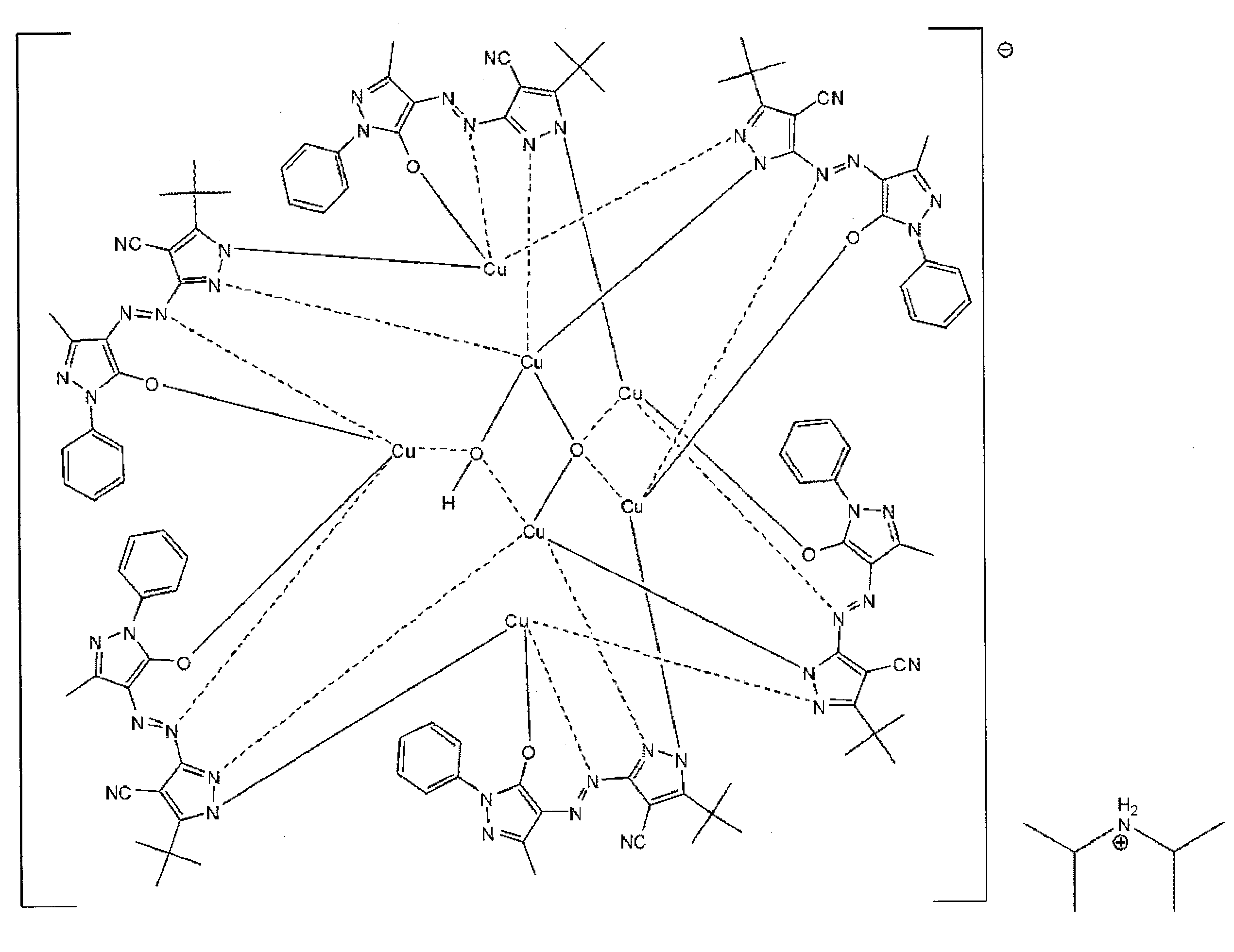
高分子バインダー Across社製ポリ酢酸ビニル(分子量Mw:101600)
500mg
[実施例1]
1.記録材料
記録材料の作製に、以下の材料を用いた。
溶媒 メチルエチルケトン(MEK) 7.0g
2光子吸収色素 下記の化合物D-1 70mg
500mg
上記のM-11化合物の合成方法について、簡単に説明する。アゾ金属錯体色素(M-11)は、下記のアゾ色素(L-11)を原料とした。
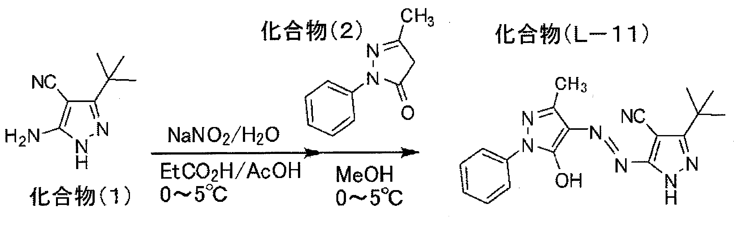
[(M-11)の合成]
3L3つ口フラスコに化合物(L-11)120g、メタノール1200mlを入れ、攪拌しながらジイソプロピルアミン193mlを滴下した。完溶させた後、攪拌しながら、さらに酢酸銅一水和物 82.3gを加え、60~65℃で2時間反応させた。室温に戻し、沈殿物をろ過し、メタノールにて洗浄し、乾燥を施し化合物(M-11)117gを得た。
3L3つ口フラスコに化合物(L-11)120g、メタノール1200mlを入れ、攪拌しながらジイソプロピルアミン193mlを滴下した。完溶させた後、攪拌しながら、さらに酢酸銅一水和物 82.3gを加え、60~65℃で2時間反応させた。室温に戻し、沈殿物をろ過し、メタノールにて洗浄し、乾燥を施し化合物(M-11)117gを得た。
2.記録層の形成
上記の溶媒に、2光子吸収色素、1光子吸収色素、高分子バインダーを撹拌・溶解させた塗布液を作り、ガラス基板上にスピンコートにより膜を形成した。膜厚は1μmとした。なお、上記の2光子吸収色素は、記録光の波長(522nm)に線形吸収を持たない。また、作製された記録層の1光子吸収色素の記録光に対する吸収率(1光子吸収)は、1.8%であった。
上記の溶媒に、2光子吸収色素、1光子吸収色素、高分子バインダーを撹拌・溶解させた塗布液を作り、ガラス基板上にスピンコートにより膜を形成した。膜厚は1μmとした。なお、上記の2光子吸収色素は、記録光の波長(522nm)に線形吸収を持たない。また、作製された記録層の1光子吸収色素の記録光に対する吸収率(1光子吸収)は、1.8%であった。
3.評価
記録光(パルスレーザ:波長522nm、繰り返し周波数3GHz、パルス幅500fsec、平均パワーPa=5~50mW、ピークパワーPp=3~33W)をピークパワー10Wで記録層に照射した。
記録層に対し、光軸方向に記録光の焦点位置を0.4μmずつ4μmの範囲(つまり、深さ方向で11点の位置)で動かし、各深さ位置(焦点位置)で、4点の記録(つまり、計44箇所での記録)をテストした。
記録条件は、記録時間を5μs~5msの間で調整した。そして、記録マークが12個(隣接する焦点位置で3箇所、その各焦点位置で4個)ずつ記録できる記録時間[μs]をデータとして得た。
記録光(パルスレーザ:波長522nm、繰り返し周波数3GHz、パルス幅500fsec、平均パワーPa=5~50mW、ピークパワーPp=3~33W)をピークパワー10Wで記録層に照射した。
記録層に対し、光軸方向に記録光の焦点位置を0.4μmずつ4μmの範囲(つまり、深さ方向で11点の位置)で動かし、各深さ位置(焦点位置)で、4点の記録(つまり、計44箇所での記録)をテストした。
記録条件は、記録時間を5μs~5msの間で調整した。そして、記録マークが12個(隣接する焦点位置で3箇所、その各焦点位置で4個)ずつ記録できる記録時間[μs]をデータとして得た。
[比較例1]
実施例1に対し、2光子吸収色素を添加せず、1光子吸収色素および高分子バインダーからなる記録層を作製した。材料の量、その他の条件は実施例1と同じである。
実施例1に対し、2光子吸収色素を添加せず、1光子吸収色素および高分子バインダーからなる記録層を作製した。材料の量、その他の条件は実施例1と同じである。
[比較例2]
実施例1に対し、1光子吸収色素を添加せず、2光子吸収色素および高分子バインダーからなる記録層を作製した。材料の量、その他の条件は実施例1と同じである。
実施例1に対し、1光子吸収色素を添加せず、2光子吸収色素および高分子バインダーからなる記録層を作製した。材料の量、その他の条件は実施例1と同じである。
[比較例3]
実施例1に対し、2光子吸収色素および1光子吸収色素を添加せず、高分子バインダーからなる記録層を作製した。材料の量、その他の条件は実施例1と同じである。
実施例1に対し、2光子吸収色素および1光子吸収色素を添加せず、高分子バインダーからなる記録層を作製した。材料の量、その他の条件は実施例1と同じである。
[結果]
所定数の気泡が形成されるまでの時間などをまとめた結果が以下の表である。
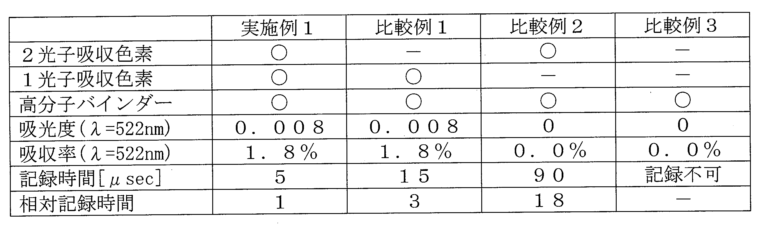
表中、○は含有すること、-は含有しないことを示す。
所定数の気泡が形成されるまでの時間などをまとめた結果が以下の表である。
上記の表に示したように、実施例1では、2光子吸収色素が無い場合(比較例1)に比べて、記録時間が3分の1となり、1光子吸収色素が無い場合(比較例2)に比べて記録時間が18分の1となった。すなわち、本発明の光情報記録媒体では、それだけ記録感度が高くなり、記録速度を高くできることが確認された。なお、高分子バインダーだけで、2光子吸収色素および1光子吸収色素が無い場合には、記録(気泡)はできなかった。
[記録の消去]
実施例1で気泡による記録マークを記録した光情報記録媒体について、80℃1時間、オーブンで加熱した。気泡による記録マークが消えた。すなわち、記録の消去が可能であることが確認された。
実施例1で気泡による記録マークを記録した光情報記録媒体について、80℃1時間、オーブンで加熱した。気泡による記録マークが消えた。すなわち、記録の消去が可能であることが確認された。
Claims (12)
- 多光子吸収化合物および1光子吸収化合物を有する記録層と、前記記録層を支持する支持体とを備え、前記多光子吸収化合物による多光子の吸収と前記1光子化合物による1光子の吸収に伴って気泡を発生し、当該気泡の有無による変調で情報が記録されることを特徴とする光情報記録媒体。
- 前記多光子吸収化合物および前記1光子吸収化合物の少なくとも一方は、光の吸収による温度の上昇により気泡を発生する発泡性材料であることを特徴とする請求項1に記載の光情報記録媒体。
- 前記記録層は、前記多光子吸収化合物および前記1光子吸収化合物とは別に、前記多光子吸収化合物および前記1光子吸収化合物の光の吸収による温度上昇により気泡を発生する気化材料を含むことを特徴とする請求項1に記載の光情報記録媒体。
- 前記記録層は、高分子バインダーを含み、加熱により気泡の消去が可能であることを特徴とする請求項1に記載の光情報記録媒体。
- 発生する気泡の大きさが0.01~10μmの範囲にあることを特徴とする請求項1に記載の光情報記録媒体。
- 前記記録層は、厚みが0.01~10μmであることを特徴とする請求項1に記載の光情報記録媒体。
- 前記記録層は複数層設けられ、
前記各記録層の間に、情報を記録するときに照射される記録光および情報を再生するときに照射される読出光のいずれも実質的に1光子吸収および多光子吸収することがない中間層をさらに備えることを特徴とする請求項6に記載の光情報記録媒体。 - 前記記録層は、前記記録光に対する1光子吸収の吸収率が1層あたり5%以下であることを特徴とする請求項7に記載の光情報記録媒体。
- 多光子吸収化合物および1光子吸収化合物を有する記録層と、前記記録層を支持する支持体とを備える光情報記録媒体に情報を記録する光情報記録方法であって、
記録すべき情報に応じて変調したパルスレーザ光を前記記録層に照射し、前記多光子吸収化合物の多光子吸収反応および前記1光子吸収化合物の1光子吸収反応を起こさせることで、前記変調に応じた位置に気泡を発生させて当該気泡の有無による変調で情報を記録することを特徴とする光情報記録方法。 - 請求項4に記載の光情報記録媒体に記録された情報の消去方法であって、
前記記録層を加熱することで、当該記録層に記録された情報を消去することを特徴とする消去方法。 - 前記記録層に焦点を合わせるように連続波レーザを照射することで、前記記録層を加熱することを特徴とする請求項10に記載の消去方法。
- 光情報記録媒体の全体を加熱することで、すべての前記記録層に記録された情報を消去することを特徴とする請求項10に記載の消去方法。
Priority Applications (2)
| Application Number | Priority Date | Filing Date | Title |
|---|---|---|---|
| CN201180034475.7A CN102985974B (zh) | 2010-07-13 | 2011-06-27 | 光学信息记录介质和光学信息记录方法 |
| US13/714,645 US8670296B2 (en) | 2010-07-13 | 2012-12-14 | Optical information recording medium and optical information recording method |
Applications Claiming Priority (2)
| Application Number | Priority Date | Filing Date | Title |
|---|---|---|---|
| JP2010158581A JP2012022734A (ja) | 2010-07-13 | 2010-07-13 | 光情報記録媒体および光情報記録方法 |
| JP2010-158581 | 2010-07-13 |
Related Child Applications (1)
| Application Number | Title | Priority Date | Filing Date |
|---|---|---|---|
| US13/714,645 Continuation US8670296B2 (en) | 2010-07-13 | 2012-12-14 | Optical information recording medium and optical information recording method |
Publications (1)
| Publication Number | Publication Date |
|---|---|
| WO2012008289A1 true WO2012008289A1 (ja) | 2012-01-19 |
Family
ID=45469297
Family Applications (1)
| Application Number | Title | Priority Date | Filing Date |
|---|---|---|---|
| PCT/JP2011/064673 Ceased WO2012008289A1 (ja) | 2010-07-13 | 2011-06-27 | 光情報記録媒体および光情報記録方法 |
Country Status (4)
| Country | Link |
|---|---|
| US (1) | US8670296B2 (ja) |
| JP (1) | JP2012022734A (ja) |
| CN (1) | CN102985974B (ja) |
| WO (1) | WO2012008289A1 (ja) |
Cited By (1)
| Publication number | Priority date | Publication date | Assignee | Title |
|---|---|---|---|---|
| US20140153375A1 (en) * | 2011-09-12 | 2014-06-05 | Fujifilm Corporation | Optical information recording medium, method for manufacturing same and recording method for optical information recording medium |
Families Citing this family (2)
| Publication number | Priority date | Publication date | Assignee | Title |
|---|---|---|---|---|
| JP5603276B2 (ja) * | 2011-03-28 | 2014-10-08 | 富士フイルム株式会社 | 光情報記録媒体 |
| WO2014136486A1 (ja) * | 2013-03-08 | 2014-09-12 | 富士フイルム株式会社 | 光情報記録媒体 |
Citations (5)
| Publication number | Priority date | Publication date | Assignee | Title |
|---|---|---|---|---|
| JP2004347642A (ja) * | 2003-05-20 | 2004-12-09 | Nitto Denko Corp | 再書き込み可能な光学素子材料 |
| JP2005037658A (ja) * | 2003-07-14 | 2005-02-10 | Fuji Photo Film Co Ltd | 2光子吸収発泡材料、3次元的屈折率変調材料及び3次元光記録媒体 |
| JP2009170013A (ja) * | 2008-01-11 | 2009-07-30 | Sony Corp | 光情報記録方法、光情報記録媒体、光情報再生装置、光情報再生方法及び光情報記録再生装置 |
| JP2010086568A (ja) * | 2008-09-29 | 2010-04-15 | Fujifilm Corp | 2光子吸収光記録媒体 |
| JP2010122373A (ja) * | 2008-11-18 | 2010-06-03 | Sony Corp | 光情報記録媒体及び2光子吸収材料 |
Family Cites Families (10)
| Publication number | Priority date | Publication date | Assignee | Title |
|---|---|---|---|---|
| US6483735B1 (en) * | 1989-04-25 | 2002-11-19 | The Regents Of The University Of California | Two-photon, three-or four-dimensional, color radiation memory |
| US5472929A (en) * | 1994-07-28 | 1995-12-05 | Nitto Denko Corporation | Reversible heat-sensitive recording medium and magnetic card using the same |
| JP3431386B2 (ja) * | 1995-03-16 | 2003-07-28 | 株式会社東芝 | 記録素子およびドリフト移動度変調素子 |
| JP2006107579A (ja) * | 2004-10-01 | 2006-04-20 | Ricoh Co Ltd | 多層相変化型情報記録媒体とその初期化装置、初期化方法、記録再生方法及び記録再生装置 |
| WO2007116401A1 (en) * | 2006-04-10 | 2007-10-18 | Mempile Inc. | Secured optical information carrier, and data encryption method and apparatus for recording data in the optical information carrier |
| JP2007294055A (ja) * | 2006-04-27 | 2007-11-08 | Hitachi Maxell Ltd | 光情報記録媒体及び光情報記録媒体の製造方法 |
| JP2009087522A (ja) * | 2007-09-13 | 2009-04-23 | Ricoh Co Ltd | 増感手段の発現の有無を記録原理とする光記録方法及び再生方法 |
| CN101652811A (zh) * | 2007-12-11 | 2010-02-17 | 松下电器产业株式会社 | 信息记录介质以及信息记录介质的评价方法 |
| JP5264589B2 (ja) * | 2008-03-28 | 2013-08-14 | 富士フイルム株式会社 | 同時2光子吸収3次元光記録媒体および同時2光子3次元光記録方法 |
| JP4826636B2 (ja) * | 2009-01-19 | 2011-11-30 | ソニー株式会社 | 光情報記録媒体 |
-
2010
- 2010-07-13 JP JP2010158581A patent/JP2012022734A/ja active Pending
-
2011
- 2011-06-27 WO PCT/JP2011/064673 patent/WO2012008289A1/ja not_active Ceased
- 2011-06-27 CN CN201180034475.7A patent/CN102985974B/zh not_active Expired - Fee Related
-
2012
- 2012-12-14 US US13/714,645 patent/US8670296B2/en not_active Expired - Fee Related
Patent Citations (5)
| Publication number | Priority date | Publication date | Assignee | Title |
|---|---|---|---|---|
| JP2004347642A (ja) * | 2003-05-20 | 2004-12-09 | Nitto Denko Corp | 再書き込み可能な光学素子材料 |
| JP2005037658A (ja) * | 2003-07-14 | 2005-02-10 | Fuji Photo Film Co Ltd | 2光子吸収発泡材料、3次元的屈折率変調材料及び3次元光記録媒体 |
| JP2009170013A (ja) * | 2008-01-11 | 2009-07-30 | Sony Corp | 光情報記録方法、光情報記録媒体、光情報再生装置、光情報再生方法及び光情報記録再生装置 |
| JP2010086568A (ja) * | 2008-09-29 | 2010-04-15 | Fujifilm Corp | 2光子吸収光記録媒体 |
| JP2010122373A (ja) * | 2008-11-18 | 2010-06-03 | Sony Corp | 光情報記録媒体及び2光子吸収材料 |
Cited By (1)
| Publication number | Priority date | Publication date | Assignee | Title |
|---|---|---|---|---|
| US20140153375A1 (en) * | 2011-09-12 | 2014-06-05 | Fujifilm Corporation | Optical information recording medium, method for manufacturing same and recording method for optical information recording medium |
Also Published As
| Publication number | Publication date |
|---|---|
| US20130100791A1 (en) | 2013-04-25 |
| US8670296B2 (en) | 2014-03-11 |
| CN102985974B (zh) | 2016-04-06 |
| CN102985974A (zh) | 2013-03-20 |
| JP2012022734A (ja) | 2012-02-02 |
Similar Documents
| Publication | Publication Date | Title |
|---|---|---|
| JP5553723B2 (ja) | 光情報記録媒体 | |
| CN102985972B (zh) | 光学信息记录介质 | |
| JP5476329B2 (ja) | 光情報記録媒体 | |
| JP5406134B2 (ja) | 光情報記録媒体およびその製造方法 | |
| WO2013008529A1 (ja) | 多層構造シートとその製造方法、光情報記録媒体および多層構造シートを用いた光情報記録媒体の製造方法 | |
| JP5396343B2 (ja) | 光情報記録媒体およびその製造方法 | |
| WO2012008289A1 (ja) | 光情報記録媒体および光情報記録方法 | |
| JP6064029B2 (ja) | 光情報記録媒体 | |
| JP5528416B2 (ja) | 光情報記録媒体およびその製造方法ならびに光情報記録媒体の記録方法 | |
| CN105246699A (zh) | 记录材料及光信息记录介质 | |
| JP4154137B2 (ja) | 光情報記録媒体および情報の記録方法 | |
| JP2012203968A (ja) | 光情報記録媒体 | |
| JP2008188867A (ja) | 光情報記録媒体、情報記録方法、金属錯体化合物およびその使用方法 | |
| CN104685567B (zh) | 光学信息记录介质及其制造方法 | |
| JP5222836B2 (ja) | 光記録媒体 | |
| JP2013242939A (ja) | 記録層および光情報記録媒体 | |
| JP2011190433A (ja) | ヒドラジドキレート錯体化合物およびこれを用いた光学記録媒体 | |
| JP2012089194A (ja) | 光情報記録媒体の製造方法 | |
| JP2006297658A (ja) | 光情報記録媒体及び光情報記録媒体の記録方法 | |
| JP2013089267A (ja) | 光情報記録媒体およびその製造方法、ならびに記録層 | |
| JP2013077350A (ja) | 光記録媒体 |
Legal Events
| Date | Code | Title | Description |
|---|---|---|---|
| WWE | Wipo information: entry into national phase |
Ref document number: 201180034475.7 Country of ref document: CN |
|
| 121 | Ep: the epo has been informed by wipo that ep was designated in this application |
Ref document number: 11806619 Country of ref document: EP Kind code of ref document: A1 |
|
| NENP | Non-entry into the national phase |
Ref country code: DE |
|
| 122 | Ep: pct application non-entry in european phase |
Ref document number: 11806619 Country of ref document: EP Kind code of ref document: A1 |