WO2012008201A1 - 電磁弁 - Google Patents
電磁弁 Download PDFInfo
- Publication number
- WO2012008201A1 WO2012008201A1 PCT/JP2011/060245 JP2011060245W WO2012008201A1 WO 2012008201 A1 WO2012008201 A1 WO 2012008201A1 JP 2011060245 W JP2011060245 W JP 2011060245W WO 2012008201 A1 WO2012008201 A1 WO 2012008201A1
- Authority
- WO
- WIPO (PCT)
- Prior art keywords
- valve
- spring
- solenoid
- coil portion
- valve body
- Prior art date
- Legal status (The legal status is an assumption and is not a legal conclusion. Google has not performed a legal analysis and makes no representation as to the accuracy of the status listed.)
- Ceased
Links
Images


Classifications
-
- F—MECHANICAL ENGINEERING; LIGHTING; HEATING; WEAPONS; BLASTING
- F16—ENGINEERING ELEMENTS AND UNITS; GENERAL MEASURES FOR PRODUCING AND MAINTAINING EFFECTIVE FUNCTIONING OF MACHINES OR INSTALLATIONS; THERMAL INSULATION IN GENERAL
- F16K—VALVES; TAPS; COCKS; ACTUATING-FLOATS; DEVICES FOR VENTING OR AERATING
- F16K31/00—Actuating devices; Operating means; Releasing devices
- F16K31/02—Actuating devices; Operating means; Releasing devices electric; magnetic
- F16K31/06—Actuating devices; Operating means; Releasing devices electric; magnetic using a magnet, e.g. diaphragm valves, cutting off by means of a liquid
- F16K31/0644—One-way valve
- F16K31/0655—Lift valves
-
- F—MECHANICAL ENGINEERING; LIGHTING; HEATING; WEAPONS; BLASTING
- F02—COMBUSTION ENGINES; HOT-GAS OR COMBUSTION-PRODUCT ENGINE PLANTS
- F02D—CONTROLLING COMBUSTION ENGINES
- F02D9/00—Controlling engines by throttling air or fuel-and-air induction conduits or exhaust conduits
- F02D9/08—Throttle valves specially adapted therefor; Arrangements of such valves in conduits
- F02D9/10—Throttle valves specially adapted therefor; Arrangements of such valves in conduits having pivotally-mounted flaps
- F02D9/1035—Details of the valve housing
- F02D9/1055—Details of the valve housing having a fluid by-pass
-
- F—MECHANICAL ENGINEERING; LIGHTING; HEATING; WEAPONS; BLASTING
- F02—COMBUSTION ENGINES; HOT-GAS OR COMBUSTION-PRODUCT ENGINE PLANTS
- F02D—CONTROLLING COMBUSTION ENGINES
- F02D9/00—Controlling engines by throttling air or fuel-and-air induction conduits or exhaust conduits
- F02D9/08—Throttle valves specially adapted therefor; Arrangements of such valves in conduits
- F02D9/12—Throttle valves specially adapted therefor; Arrangements of such valves in conduits having slidably-mounted valve members; having valve members movable longitudinally of conduit
Definitions
- the present invention includes a valve body having a valve seat, a solenoid support body joined to the valve body, a valve body that can be seated on the valve seat, and a slidable member that supports the valve body and slides on the solenoid support body.
- a plunger that is supported by the valve a valve spring that urges the valve body in a seating direction with the valve seat while surrounding the plunger, and a solenoid support that is attached to the solenoid support,
- the present invention relates to an improvement in an electromagnetic valve including a solenoid that operates the plunger against the valve to fully open the valve body.
- the valve spring is composed of a coil spring with a uniform wire diameter and coil diameter, but with only a non-uniform coil pitch, and the load characteristics of the valve spring are made non-linear corresponding to the attractive force characteristics of the solenoid. This is disclosed in Patent Document 1.
- each part is required to ensure good valve opening response when the valve body is fully closed.
- the spring constant of the valve spring is required to be as small as possible in order to give a stable and relatively small set load to the valve body without being affected by the manufacturing error of the valve body.
- the spring constant of the valve spring is required to be as large as possible. In order to satisfy such a requirement, it is desirable that the load characteristic of the valve spring has two broken line characteristics as shown in FIG. 4, and the non-linear characteristic as described in Patent Document 1 satisfies it. Is difficult.
- the present invention has been made in view of such circumstances.
- the valve spring is provided with two polygonal line load characteristics, and the open / close response of the valve body is improved without affecting the manufacturing error of each part.
- An object of the present invention is to provide a solenoid valve that can be made to operate.
- the present invention provides a valve body having a valve seat, a solenoid support body joined to the valve body, a valve body that can be seated on the valve seat, and a valve body that supports the valve body.
- a plunger slidably supported by the solenoid support, a valve spring for energizing the valve body in a seating direction with the valve seat while surrounding the plunger, and a solenoid spring attached to the solenoid support.
- An electromagnetic valve comprising a solenoid that operates the plunger toward the fully open side against the biasing force of the valve spring, wherein the valve spring includes a conical coil portion and a small-diameter end of the conical coil portion. And a cylindrical coil portion extending with the same diameter as that of the first coil spring, and the spring constant of the cylindrical coil portion is set larger than that of the conical coil portion.
- the present invention provides a spring that supports the large-diameter end of the conical coil portion by compressing and deforming the conical coil portion in a single plane at the intermediate opening position of the valve body.
- the second feature is that it is in close contact with the seat.
- the spring seat corresponds to the lower end plate 15b of the yoke 15 in the embodiment of the present invention described later.
- the conical coil portion is fitted into a spring positioning hole formed concentrically with the plunger in the solenoid support, and the cylindrical coil portion is fitted to the plunger.
- the third feature is that they are arranged concentrically on the outer periphery.
- the present invention embeds a yoke covering the outer periphery and both axial ends of the solenoid in the solenoid support, and connects one end plate of the yoke to the large-diameter end of the conical coil portion.
- a fourth feature is that the spring positioning hole is exposed to the spring positioning hole.
- the spring load characteristic of the valve spring depends on the low spring constant of the conical coil portion at the initial opening of the valve body, and the cylindrical coil portion after the intermediate opening of the valve body. It has two broken line load characteristics that depend on the high spring constant. Therefore, the increase in the load of the valve spring that accompanies the opening of the valve element is moderate at the initial stage of opening the valve element, so that it is relatively small relative to the valve element of the valve spring without affecting the manufacturing error of each part.
- the valve closing load can be stabilized, and the valve opening response of the valve body when the solenoid is energized can always be improved.
- valve load on the valve body of the valve spring can be increased rapidly after the predetermined intermediate opening of the valve body, the valve closing response of the valve body when the solenoid is de-energized when the valve body is fully open is improved. can do.
- valve spring has a conical coil portion, the expansion and contraction posture of the valve spring can be stabilized and buckling can be prevented, so that an appropriate spring load characteristic can always be exhibited.
- the conical coil portion is compressed and deformed in a single plane and is in close contact with the spring seat, and thereafter, the conical coil portion is While only the cylindrical coil is activated, the valve closing load on the valve element can be increased rapidly and accurately, so the valve element when the solenoid is de-energized with the valve element fully open. It is possible to further improve the valve closing response.
- the valve spring is always held concentrically with the plunger, and during the expansion / contraction, the plunger does not give side thrust, so the plunger slides smoothly, This can contribute to further improvement in the opening / closing response of the valve body.
- the one end plate of the yoke also serves as a spring seat for the conical coil portion, which can contribute to simplification of the structure.
- FIG. 1 is a longitudinal sectional view of a solenoid valve according to an embodiment of the present invention.
- FIG. 2 is an enlarged view of part 2 of FIG.
- FIG. 3 is an operation explanatory diagram corresponding to FIG. (First embodiment)
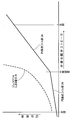
- FIG. 4 is a load characteristic diagram of the valve spring in FIG. (First embodiment)
- a throttle body T attached to an engine has an intake passage 1 connected to an intake port of the engine, and is a butterfly type that opens and closes the intake passage 1 to control the amount of intake passage of the engine.
- the throttle valve 2 is pivotally supported on the throttle body T.
- a bypass 3 that bypasses the throttle body T and communicates between the upstream and downstream portions of the intake passage 1 is connected to the throttle body T, and the solenoid valve V of the present invention is interposed in the middle of the bypass 3.
- This electromagnetic valve V is a normally closed type, and the bypass 3 can be conducted by opening the valve.
- the electromagnetic valve V will be described in detail with reference to FIGS.
- the solenoid valve V includes a throttle body T or a valve body 5 supported by the engine and a solenoid support body 6 joined to the valve body 5 by bolts 7.
- a positioning cylinder portion 9 protruding from the bottom surface of the solenoid support 6 is fitted in a circular recess 8 formed on the top surface of the valve body 5.
- the sealing member 22 is interposed in the fitting portion.
- valve body 5 is formed with a valve seat 10 that is annularly raised from the center of the bottom surface of the circular recess 8, and the inlet hole 11 that opens to the bottom surface of the circular recess 8 outside the valve seat 10 has the above-mentioned
- An upstream portion 3 a of the bypass 3 is connected, and a downstream portion 3 b of the bypass 3 is connected to the valve hole 12 in the valve seat 10.
- the solenoid support 6 is made of synthetic resin.
- the solenoid support 6 includes a bobbin 13, a solenoid 14 wound around the bobbin 13, a yoke 15 that surrounds the outer periphery of the solenoid 14, and bends at both the upper and lower ends of the bobbin 13.
- a cylindrical fixed core 16 that is fitted into the hollow portion of the yoke 15 and is caulked and joined integrally to the upper end plate 15a of the yoke 15, and a power supply terminal 17 connected to the solenoid 14 are embedded. It is arranged so that the tip portion faces the coupler 18 that is integrally projected on the upper side surface of the support 6.
- the lower end plate 15b of the yoke 15 is provided with a through hole 19 having the same diameter as or slightly larger than the hollow portion of the bobbin 13, and a spring positioning hole having a larger diameter connected to the through hole 19 20 is provided at the center of the positioning cylinder 9.
- the bobbin 13, the through hole 19, the spring positioning hole 20, and the valve seat 10 are disposed on the same axis.
- a plunger 21 as a movable core that penetrates the through hole 19 and faces the lower end surface of the fixed core 16 is slidably fitted to the lower portion of the hollow portion of the heel bobbin 13.
- the lower end portion of the plunger 21 protrudes downward from the positioning cylinder portion 9, and as shown in FIG. 2, the lower end portion of the plunger 21 has first, second, and second diameters that gradually decrease in diameter downward.
- Three small diameter portions 21a, 21b, and 21c are formed, and their axial lengths increase from the first small diameter portion 21a toward the third small diameter portion 21c.
- a disc-shaped spring seat 23 having a larger diameter than the valve seat 10 is slidably fitted to the first small-diameter portion 21a, and a disc-shaped valve that can be seated on the valve seat 10 is fitted to the second small-diameter portion 21b.
- the body 24 is fitted over the entire length of the second small diameter portion 21b.
- a holding member 25 having a diameter sufficiently smaller than the valve hole 12 is fixed to the third small diameter portion 21c having the smallest diameter by press fitting, and the valve body 24 is held on the second small diameter portion 21b by the holding member 25.
- the valve body 24 is made of an elastic material such as rubber, and an annular groove 26 for imparting good flexibility to the valve body 24 is formed on the upper end surface thereof.
- a valve spring 28 for urging the valve body 24 in the seating direction on the valve seat 10 is contracted and fixed when the valve body 24 is seated on the valve seat 10.
- a constant gap g corresponding to the valve opening stroke of the valve body 24 is provided between the core 16 and the plunger 21.
- the valve spring 28 has a single conical coil part 29 and a cylindrical coil part 30 extending from the small diameter end 29b of the conical coil part 29 with the same diameter.
- the conical coil portion 29 is composed of a coil spring, and is arranged so that its large-diameter end 29a is fitted to the inner peripheral surface of the spring positioning hole 20 and supported on the lower end plate 15b of the yoke 15.
- the coil portion 30 is disposed concentrically on the outer periphery of the plunger 21 and makes its lower end abut against the spring seat 23.
- valve spring 28 comprising the conical coil part 29 and the cylindrical coil part 30 is made of a single wire having a uniform wire diameter, and the spring constant of the cylindrical coil part 30 is determined by the conical coil part. It is set to be greater than 29. Further, the conical coil portion 29 having a low spring constant is compressed and deformed in a single flat shape while the valve element 24 is being opened, and is in close contact with the lower end plate of the yoke 15 (see FIG. 3A). ).
- the plunger 21 is attracted to the fixed core 16 against the urging force of the valve spring 28 and the valve body 24 is separated from the valve seat 10 ( As shown in FIG. 3B, the upstream portion 3a and the downstream portion 3b of the bypass 3 are electrically connected, so that the intake air for the first idling can be supplied to the engine through the bypass 3.
- the energization of the solenoid 14 is cut off, so that the plunger 21 is in a fully closed state (see FIG. 2) in which the valve body 24 is seated on the valve seat 10 by the biasing force of the valve spring 28. Since the upstream portion 3a and the downstream portion 3b are blocked, normal intake air for idling can be supplied to the engine through the throttle valve 2 around the idle opening.
- the valve spring 28 is a single coil consisting of the small-diameter end 29b of the conical coil portion 29 having a low spring constant and the cylindrical coil portion 30 having the same diameter as the small-diameter end 29b and a high spring constant. Since it is constituted by a coil spring, its spring load characteristic depends on the low spring constant of the conical coil portion 29 at the initial opening of the valve body 24 as shown in FIG. Then, it becomes two broken line load characteristics that depend on the high spring constant of the cylindrical coil portion 30.
- valve spring 28 an increase in the load of the valve spring 28 accompanying the opening of the valve body 24 is moderate in the initial stage of the valve body 24 opening, and thereby the valve spring 28 does not affect the manufacturing error of each part. Since a relatively small valve closing load on the body 24 can be stabilized, the valve opening response of the valve body 24 when the solenoid 14 is energized can always be improved. Further, at a predetermined intermediate opening position of the valve body 24, as shown in FIG.
- the conical coil portion 29 is compressed and deformed into a flat surface and is in close contact with the lower end plate of the yoke 15, and thereafter, While the conical coil portion 29 is inoperative, only the cylindrical coil portion 30 is activated, and the valve closing load on the valve body 24 of the valve spring 28 can be rapidly increased.
- the valve closing response of the valve body 24 when the energization of the solenoid 14 is cut off can be improved.
- the conical coil portion 29 of the valve spring 28 is supported by the lower end plate 15b of the yoke 15 serving as a spring seat at the large diameter end 29a, thereby stabilizing the expansion and contraction posture of the valve spring 28 and preventing buckling. Therefore, the proper spring load characteristics can always be exhibited.
- the conical coil portion 29 is fitted into a spring positioning hole 20 formed concentrically with the bobbin 13 and the plunger 21 in the solenoid support 6, and the cylindrical coil portion 30 is disposed concentrically on the outer periphery of the plunger 21.
- the valve spring 28 is always held concentrically with the plunger 21, and side thrust is not applied to the plunger 21 during expansion / contraction, so that the plunger 21 slides smoothly and the valve body 24 opens and closes. It can contribute to further improvement of sex.
- the lower end plate 15b of the yoke 15 embedded in the solenoid support 6 is disposed so as to be exposed to the spring positioning hole 20 of the solenoid support 6 as a spring seat for supporting the large diameter end 29a of the conical coil portion 29. Therefore, the lower end plate 15b of the yoke 15 also serves as a spring seat for the conical coil portion 29, which can contribute to simplification of the structure.
- valve spring 28 is inverted upside down from the embodiment, the conical coil portion 29 is on the valve body 24 side, and the cylindrical coil portion 30 is on the yoke 15 side. It can also be arranged.
Landscapes
- Engineering & Computer Science (AREA)
- General Engineering & Computer Science (AREA)
- Mechanical Engineering (AREA)
- Chemical & Material Sciences (AREA)
- Combustion & Propulsion (AREA)
- Magnetically Actuated Valves (AREA)
Abstract
弁座を有する弁ボディと,これに接合されるソレノイド支持体と,弁座に着座し得る弁体と,この弁体を支持してソレノイド支持体に摺動自在に支持されるプランジャと,弁体を弁座との着座方向に付勢する弁ばねと,ソレノイド支持体に取り付けられ,通電時,弁ばねの付勢力に抗してプランジャを弁体の全開側に作動するソレノイドとよりなる電磁弁において,弁ばね(28)を,円錐状コイル部(29)と,この円錐状コイル部(29)の小径端(29b)から,それと同径で延出する円筒状コイル部(30)とを有する単一のコイルばねで構成し,その円筒状コイル部(30)のばね定数を円錐状コイル部(29)のそれより大きく設定した。これにより、簡単な構造をもって,弁ばねに二本の折れ線荷重特性を与え,各部の製作誤差に影響させることなく弁体の開閉応答性を向上させ得るようにした電磁弁を提供することができる。
Description
本発明は,弁座を有する弁ボディと,この弁ボディに接合されるソレノイド支持体と,前記弁座に着座し得る弁体と,この弁体を支持して前記ソレノイド支持体に摺動自在に支持されるプランジャと,このプランジャを囲繞しながら前記弁体を前記弁座との着座方向に付勢する弁ばねと,前記ソレノイド支持体に取り付けられ,通電時,前記弁ばねの付勢力に抗して前記プランジャを作動して前記弁体を全開させるソレノイドとよりなる電磁弁の改良に関する。
かゝる電磁弁において,弁ばねを,線径及びコイル径が均一でコイルピッチのみが不均一なコイルばねで構成して,弁ばねの荷重特性を,ソレノイドの吸引力特性に対応した非線形にさせたものが,特許文献1に開示されている。
ところで,ソレノイドへの通電,非通電に応じて弁体を全開,全閉にするオン・オフ型の電磁弁では,弁体の全閉位置では,良好な開弁応答性を確保すべく,各部の製作誤差に影響されずに弁体に安定した比較的小さなセット荷重を付与するために,弁ばねのばね定数は極力小さいことが要求され,弁体の全開位置では,良好な閉弁応答性を確保すべく,弁体に比較的大きな閉弁荷重を付与するために,弁ばねのばね定数は極力大きいことが要求される。このような要求を満足させるには,弁ばねの荷重特性が,図4に示すような二本の折れ線特性となることが望ましく,特許文献1に記載のような非線形特性では,それを満足させることが困難である。
本発明は,かゝる事情に鑑みてなされたもので,簡単な構造をもって,弁ばねに二本の折れ線荷重特性を与え,各部の製作誤差に影響させることなく弁体の開閉応答性を向上させ得るようにした電磁弁を提供することを目的とする。
上記目的を達成するために,本発明は,弁座を有する弁ボディと,この弁ボディに接合されるソレノイド支持体と,前記弁座に着座し得る弁体と,この弁体を支持して前記ソレノイド支持体に摺動自在に支持されるプランジャと,このプランジャを囲繞しながら前記弁体を前記弁座との着座方向に付勢する弁ばねと,前記ソレノイド支持体に取り付けられ,通電時,前記弁ばねの付勢力に抗して前記プランジャを前記弁体の全開側に作動するソレノイドとよりなる電磁弁において,前記弁ばねを,円錐状コイル部と,この円錐状コイル部の小径端から,それと同径で延出する円筒状コイル部とを有する単一のコイルばねで構成し,その円筒状コイル部のばね定数を前記円錐状コイル部のそれより大きく設定したことを第1の特徴とする。
また本発明は,第1の特徴に加えて,前記弁体の中間開度位置では,前記円錐状コイル部が一平面状に圧縮変形して,円錐状コイル部の大径端を支持するばね座に密着するようにしたことを第2の特徴とする。尚,前記ばね座は,後述する本発明の実施形態中のヨーク15の下端板15bに対応する。
さらに本発明の第2の特徴に加えて,前記円錐状コイル部を,前記ソレノイド支持体に前記プランジャと同心状に形成したばね位置決め孔に嵌合すると共に,前記円筒状コイル部を前記プランジャの外周に同心状に配置したことを第3の特徴とする。
さらにまた本発明は,第3の特徴に加えて,前記ソレノイドの外周及び軸方向両端を覆うヨークを前記ソレノイド支持体に埋設し,このヨークの一端板を,前記円錐状コイル部の大径端を支持するばね座として前記ばね位置決め孔に露出させたことを第4の特徴とする。
本発明の第1の特徴によれば,弁ばねのばね荷重特性は,弁体の開弁初期では円錐状コイル部の低ばね定数に依存し,弁体の中間開度以降では円筒状コイル部の高ばね定数に依存するという,二本の折れ線荷重特性となる。したがって,弁体の開弁に伴なう弁ばねの荷重の増加は,弁体の開弁初期では緩やかとなるので,各部の製作誤差に影響させることなく,弁ばねの弁体に対する比較的小さい閉弁荷重を安定させ,ソレノイドの通電時の弁体の開弁応答性を常に良好にすることができる。弁体の所定の中間開度以降では,弁ばねの弁体に対する閉弁荷重を急増させることができるので,弁体の全開状態におけるソレノイドの通電遮断時の弁体の閉弁応答性を良好にすることができる。しかも,弁ばねは,円錐状コイル部を有することで,弁ばねの伸縮姿勢を安定させ,座屈を防ぐことができるので,常に適正なばね荷重特性を発揮することができる。
本発明の第2の特徴によれば,弁体の所定の中間開度位置では,円錐状コイル部が一平面状に圧縮変形されてばね座に密着し,それ以降は,円錐状コイル部は非作動状態となる一方,円筒状コイル部のみが作動して,弁ばねの弁体に対する閉弁荷重を的確に急増させることができるので,弁体の全開状態におけるソレノイドの通電遮断時の弁体の閉弁応答性を一層良好にすることができる。
本発明の第3の特徴によれば,弁ばねは常にプランジャと同心状に保持されることになり,その伸縮中,プランジャにサイドスラストを与えることがないから,プランジャの摺動はスムーズとなり,弁体の開閉応答性の更なる向上に寄与し得る。
本発明の第4の特徴によれば,ヨークの一端板が円錐状コイル部のためのばね座を兼ねることになり,構造の簡素化に寄与し得る。
V・・・・電磁弁
5・・・・弁ボディ
6・・・・ソレノイド支持体
10・・・弁座
14・・・ソレノイド
15・・・ヨーク
15b・・ヨークの一端板(ばね座)
20・・・ばね位置決め孔
21・・・プランジャ
24・・・弁体
28・・・弁ばね
29・・・円錐状コイル部
30・・・円筒状コイル部
5・・・・弁ボディ
6・・・・ソレノイド支持体
10・・・弁座
14・・・ソレノイド
15・・・ヨーク
15b・・ヨークの一端板(ばね座)
20・・・ばね位置決め孔
21・・・プランジャ
24・・・弁体
28・・・弁ばね
29・・・円錐状コイル部
30・・・円筒状コイル部
本発明の実施の形態を添付図面に基づいて以下に説明する。
先ず図1において,図示しないエンジンに取り付けられるスロットルボディTは,エンジンの吸気ポートに連なる吸気道1を有しており,この吸気道1を開閉してエンジンの吸気道量を制御するバタフライ型のスロットル弁2がスロットルボディTに軸支される。またスロットルボディTには,スロットルボディTを迂回して吸気道1の上流及び下流部間を連通するバイパス3が接続され,このバイパス3の途中に本発明の電磁弁Vが介装される。この電磁弁Vは常閉型で,その開弁によりバイパス3を導通させることができる。
この電磁弁Vについて図1及び図2により詳しく説明する。
電磁弁Vは,スロットルボディT又はエンジンに支持される弁ボディ5と,それにボルト7により接合されるソレノイド支持体6とを備える。これら弁ボディ5及びソレノイド支持体6相互の接合位置を規定すべく,弁ボディ5の上面に形成される円形凹部8に,ソレノイド支持体6の下面に突設される位置決め筒部9が嵌合され,その嵌合部にはシール部材22が介装される。
また弁ボディ5には,前記円形凹部8の底面中心部から環状に隆起する弁座10が形成されており,弁座10の外側の円形凹部8の底面に開口する入口孔11には,前記バイパス3の上流部3aが接続され,弁座10内の弁孔12には,前記バイパス3の下流部3bが接続される。
ソレノイド支持体6は合成樹脂製である。このソレノイド支持体6には,ボビン13と,それに巻装されるソレノイド14と,このソレノイド14の外周を囲んでボビン13の上下両端側に屈曲するヨーク15と,ボビン13の上端からその中間部にかけてその中空部に嵌装されてヨーク15の上端板15aに一体的にカシメ結合される円柱状の固定コア16と,ソレノイド14に連なる給電端子17とが埋設され,その給電端子17は,ソレノイド支持体6の上部一側面に一体に突設されるカプラ18内に先端部を臨ませるように配置される。
ヨーク15の下端板15bには,ボビン13の中空部に連なる,それと同径もしくはそれより僅かに大径の透孔19が設けられ,この透孔19に連なる,それより大径のばね位置決め孔20が位置決め筒部9の中心部に設けられる。上記ボビン13,透孔19,ばね位置決め孔20及び弁座10は,同一軸線上に配置される。
ボビン13の中空部の下部には,透孔19を貫通して固定コア16の下端面に対向する可動コアとしてのプランジャ21が摺動自在に嵌装される。このプランジャ21の下端部は,位置決め筒部9の下方に突出しており,その下端部には,図2に明示するように,下方に向かって段階的に縮径する第1,第2及び第3小径部21a,21b,21cが形成されており,それらの軸方向長さが第1小径部21aから第3小径部21cに向かって増加している。第1小径部21aには弁座10より大径の円板状のばね座23が摺動自在に嵌合され,第2小径部21bには,弁座10に着座し得る円板状の弁体24が第2小径部21bの全長に亙り嵌合される。最も小径の第3小径部21cには,弁孔12より充分小径の保持部材25が圧入により固着され,この保持部材25により弁体24が第2小径部21b上に保持される。弁体24はゴム等の弾性材製であって,その上端面には,弁体24に良好な可撓性を付与するための環状溝26が形成される。
ソレノイド支持体6とばね座23との間には,弁体24を弁座10への着座方向に付勢する弁ばね28が縮設され,弁体24の弁座10への着座時,固定コア16及びプランジャ21間には,弁体24の開弁ストロークに対応する一定の間隙gが設けられる。
図2に明示するように,上記弁ばね28は,円錐状コイル部29と,この円錐状コイル部29の小径端29bからそれと同径で延出する円筒状コイル部30とを有する単一のコイルばねで構成され,その円錐状コイル部29は,その大径端29aを前記ばね位置決め孔20の内周面に嵌合させてヨーク15の下端板15bに支承させるように配置され,円筒状コイル部30は,プランジャ21の外周に同心状に配置されると共に,その下端をばね座23に当接させる。
このように円錐状コイル部29及び円筒状コイル部30よりなる弁ばね28は,線径を均一にした一本の線材よりなるもので,円筒状コイル部30のばね定数は,円錐状コイル部29のそれより大きく設定される。また低ばね定数の円錐状コイル部29は,弁体24の開弁途中で全体が一平面状に圧縮変形してヨーク15の下端板に密着するようになっている(図3(a)参照)。
次に,この実施形態の作用について説明する。
エンジンの暖機運転時には,ソレノイド14への通電により,プランジャ21は,弁ばね28の付勢力に抗して固定コア16に吸着され,弁体24を弁座10から離座させた全開状態(図3(b)参照)とし,これによりバイパス3の上流部3a及び下流部3b間を導通させるので,このバイパス3を通してファーストアイドリング用の吸気をエンジンに供給することができる。また暖機運転完了後には,ソレノイド14への通電遮断により,プランジャ21は,弁ばね28の付勢力をもって弁体24を弁座10に着座させる全閉状態(図2参照)として,バイパス3の上流部3a及び下流部3b間を遮断するので,アイドル開度のスロットル弁2周りを通して通常のアイドリング用の吸気をエンジンに供給することができる。
ところで,弁ばね28は,前述のように,低ばね定数の円錐状コイル部29の小径端29bに,その小径端29bと同径で高ばね定数の円筒状コイル部30とよりなる単一のコイルばねで構成されるので,そのばね荷重特性は,図4に示すように,弁体24の開弁初期では円錐状コイル部29の低ばね定数に依存し,弁体24の中間開度以降では円筒状コイル部30の高ばね定数に依存するという,二本の折れ線荷重特性となる。
したがって,弁体24の開弁に伴なう弁ばね28の荷重の増加は,弁体24の開弁初期では緩やかであり,これにより各部の製作誤差に影響させることなく,弁ばね28の弁体24に対する比較的小さい閉弁荷重を安定させることができるので,ソレノイド14の通電時の弁体24の開弁応答性を常に良好にすることができる。また弁体24の所定の中間開度位置では,図3(a)に示すように,円錐状コイル部29が一平面状に圧縮変形されてヨーク15の下端板に密着し,それ以降は,円錐状コイル部29は非作動状態となる一方,円筒状コイル部30のみが作動して,弁ばね28の弁体24に対する閉弁荷重を急増させることができるので,弁体24の全開状態におけるソレノイド14の通電遮断時の弁体24の閉弁応答性を良好にすることができる。
しかも,弁ばね28の円錐状コイル部29は,その大径端29aがばね座としてのヨーク15下端板15bに支持されることで,弁ばね28の伸縮姿勢を安定させ,座屈を防ぐことができるので,常に適正なばね荷重特性を発揮することができる。
さらに,円錐状コイル部29は,ソレノイド支持体6にボビン13及びプランジャ21と同心状に形成したばね位置決め孔20に嵌合され,また円筒状コイル部30はプランジャ21の外周に同心状に配置されることで,弁ばね28が常にプランジャ21と同心状に保持され,その伸縮中,プランジャ21にサイドスラストを与えることがないから,プランジャ21の摺動はスムーズとなり,弁体24の開閉応答性の更なる向上に寄与し得る。
またソレノイド支持体6に埋設されるヨーク15の下端板15bは,円錐状コイル部29の大径端29aを支持するばね座として,ソレノイド支持体6のばね位置決め孔20に露出するように配置されるので,ヨーク15の下端板15bが円錐状コイル部29のためのばね座を兼ねることになり,構造の簡素化に寄与し得る。
本発明は上記実施形態に限定されるものではなく,その要旨を逸脱しない範囲で種々の設計変更が可能である。例えば,本発明の第1及び第2の特徴においては,弁ばね28を実施形態とは上下逆に反転させて,円錐状コイル部29を弁体24側,円筒状コイル部30をヨーク15側に配置することもできる。
Claims (4)
- 弁座(10)を有する弁ボディ(5)と,この弁ボディ(5)に接合されるソレノイド支持体(6)と,前記弁座(10)に着座し得る弁体(24)と,この弁体(24)を支持して前記ソレノイド支持体(6)に摺動自在に支持されるプランジャ(21)と,このプランジャ(21)を囲繞しながら前記弁体(24)を前記弁座(10)との着座方向に付勢する弁ばね(28)と,前記ソレノイド支持体(6)に取り付けられ,通電時,前記弁ばね(28)の付勢力に抗して前記プランジャ(21)を前記弁体(24)の全開側に作動するソレノイド(14)とよりなる電磁弁において,
前記弁ばね(28)を,円錐状コイル部(29)と,この円錐状コイル部(29)の小径端(29b)から,それと同径で延出する円筒状コイル部(30)とを有する単一のコイルばねで構成し,その円筒状コイル部(30)のばね定数を前記円錐状コイル部(29)のそれより大きく設定したことを特徴とする電磁弁。 - 請求項1記載の電磁弁において,
前記弁体(24)の中間開度位置では,前記円錐状コイル部(29)が一平面状に圧縮変形して,円錐状コイル部(29)の大径端(29a)を支持するばね座(15b)に密着するようにしたことを特徴とする電磁弁。 - 請求項2記載の電磁弁において,
前記円錐状コイル部(29)を,前記ソレノイド支持体(6)に前記プランジャ(21)と同心状に形成したばね位置決め孔(20)に嵌合すると共に,前記円筒状コイル部(30)を前記プランジャ(21)の外周に同心状に配置したことを特徴とする電磁弁。 - 請求項3記載の電磁弁において,
前記ソレノイド(14)の外周及び軸方向両端を覆うヨーク(15)を前記ソレノイド支持体(6)に埋設し,このヨーク(15)の一端板(15b)を,前記円錐状コイル部(29)の大径端(29a)を支持するばね座として前記ばね位置決め孔(20)に露出させたことを特徴とする電磁弁。
Priority Applications (1)
| Application Number | Priority Date | Filing Date | Title |
|---|---|---|---|
| CN201180034317.1A CN102985736B (zh) | 2010-07-13 | 2011-04-27 | 电磁阀 |
Applications Claiming Priority (2)
| Application Number | Priority Date | Filing Date | Title |
|---|---|---|---|
| JP2010158999A JP5437186B2 (ja) | 2010-07-13 | 2010-07-13 | 電磁弁 |
| JP2010-158999 | 2010-07-13 |
Publications (1)
| Publication Number | Publication Date |
|---|---|
| WO2012008201A1 true WO2012008201A1 (ja) | 2012-01-19 |
Family
ID=45469213
Family Applications (1)
| Application Number | Title | Priority Date | Filing Date |
|---|---|---|---|
| PCT/JP2011/060245 Ceased WO2012008201A1 (ja) | 2010-07-13 | 2011-04-27 | 電磁弁 |
Country Status (3)
| Country | Link |
|---|---|
| JP (1) | JP5437186B2 (ja) |
| CN (1) | CN102985736B (ja) |
| WO (1) | WO2012008201A1 (ja) |
Cited By (2)
| Publication number | Priority date | Publication date | Assignee | Title |
|---|---|---|---|---|
| JP2013155762A (ja) * | 2012-01-26 | 2013-08-15 | Rinnai Corp | 電磁弁 |
| WO2020043329A1 (de) * | 2018-08-27 | 2020-03-05 | Vitesco Technologies GmbH | Ventil |
Families Citing this family (6)
| Publication number | Priority date | Publication date | Assignee | Title |
|---|---|---|---|---|
| JP6335693B2 (ja) * | 2014-07-08 | 2018-05-30 | Kyb株式会社 | ソレノイドバルブ |
| CN104895681A (zh) * | 2015-06-25 | 2015-09-09 | 芜湖创智机械技术有限公司 | 一种电磁式汽车节气门装置 |
| JP6709408B2 (ja) * | 2016-03-02 | 2020-06-17 | 株式会社テージーケー | 制御弁 |
| CN111344483B (zh) * | 2017-11-22 | 2022-03-08 | 日立安斯泰莫株式会社 | 燃料喷射装置 |
| US12259061B2 (en) * | 2020-04-24 | 2025-03-25 | Pierburg Gmbh | Blow-off valve |
| KR102298308B1 (ko) * | 2020-04-27 | 2021-09-06 | 금오공과대학교 산학협력단 | 변탄성 스프링의 제조방법, 이를 통해 제조된 변탄성 스프링 및 변탄성 스프링을 이용한 압력제어밸브 |
Citations (6)
| Publication number | Priority date | Publication date | Assignee | Title |
|---|---|---|---|---|
| JPS56151571U (ja) * | 1980-04-11 | 1981-11-13 | ||
| JPS578964U (ja) * | 1980-06-18 | 1982-01-18 | ||
| JPH0312071U (ja) * | 1989-06-14 | 1991-02-07 | ||
| JPH0540680U (ja) * | 1991-10-29 | 1993-06-01 | 三菱電機株式会社 | 電磁弁 |
| JP2002147638A (ja) * | 2000-11-07 | 2002-05-22 | Fuji Koki Corp | 電磁弁 |
| JP2003294164A (ja) * | 2002-04-03 | 2003-10-15 | Takano Co Ltd | 流量制御弁 |
-
2010
- 2010-07-13 JP JP2010158999A patent/JP5437186B2/ja active Active
-
2011
- 2011-04-27 CN CN201180034317.1A patent/CN102985736B/zh active Active
- 2011-04-27 WO PCT/JP2011/060245 patent/WO2012008201A1/ja not_active Ceased
Patent Citations (6)
| Publication number | Priority date | Publication date | Assignee | Title |
|---|---|---|---|---|
| JPS56151571U (ja) * | 1980-04-11 | 1981-11-13 | ||
| JPS578964U (ja) * | 1980-06-18 | 1982-01-18 | ||
| JPH0312071U (ja) * | 1989-06-14 | 1991-02-07 | ||
| JPH0540680U (ja) * | 1991-10-29 | 1993-06-01 | 三菱電機株式会社 | 電磁弁 |
| JP2002147638A (ja) * | 2000-11-07 | 2002-05-22 | Fuji Koki Corp | 電磁弁 |
| JP2003294164A (ja) * | 2002-04-03 | 2003-10-15 | Takano Co Ltd | 流量制御弁 |
Cited By (2)
| Publication number | Priority date | Publication date | Assignee | Title |
|---|---|---|---|---|
| JP2013155762A (ja) * | 2012-01-26 | 2013-08-15 | Rinnai Corp | 電磁弁 |
| WO2020043329A1 (de) * | 2018-08-27 | 2020-03-05 | Vitesco Technologies GmbH | Ventil |
Also Published As
| Publication number | Publication date |
|---|---|
| CN102985736A (zh) | 2013-03-20 |
| CN102985736B (zh) | 2014-10-08 |
| JP5437186B2 (ja) | 2014-03-12 |
| JP2012021561A (ja) | 2012-02-02 |
Similar Documents
| Publication | Publication Date | Title |
|---|---|---|
| JP5437186B2 (ja) | 電磁弁 | |
| CN102985737B (zh) | 电磁阀 | |
| CN100422543C (zh) | 气体燃料用喷射阀 | |
| US6648247B2 (en) | Combined filter and adjuster for a fuel injector | |
| CN103807065A (zh) | 电磁式燃料喷射阀 | |
| CN106605050A (zh) | 用于惯性空气循环阀的调节机构 | |
| CN100425893C (zh) | 止回阀 | |
| CN101415981A (zh) | 包含可调节分隔物的螺线管致动的流控制阀 | |
| WO2015072031A1 (ja) | 燃料噴射弁、及び燃料噴射弁の製造方法 | |
| JP2005090233A (ja) | 燃料噴射弁 | |
| JP2005233048A (ja) | 流体噴射弁 | |
| JP4583693B2 (ja) | 燃料噴射器のフィルター兼アジャスタ | |
| JP5101705B2 (ja) | 燃料噴射弁 | |
| US9057446B2 (en) | Pressure control apparatus | |
| JP2015152093A (ja) | 電磁弁 | |
| CN107542612B (zh) | 用于喷射阀的阀组件以及喷射阀 | |
| CN102782778B (zh) | 电磁阀 | |
| JP2010209719A (ja) | 燃料噴射装置 | |
| JP5042073B2 (ja) | 燃料噴射弁 | |
| JP2008291735A (ja) | 燃料噴射装置 | |
| JP2022146785A (ja) | ガス燃料用噴射弁 | |
| JP2010121636A (ja) | 燃料噴射装置 | |
| JP5891205B2 (ja) | 流体比例弁 | |
| CN109154261A (zh) | 用于喷射阀的阀组件以及喷射阀 | |
| EP1741921A8 (en) | Fuel injection valve |
Legal Events
| Date | Code | Title | Description |
|---|---|---|---|
| WWE | Wipo information: entry into national phase |
Ref document number: 201180034317.1 Country of ref document: CN |
|
| 121 | Ep: the epo has been informed by wipo that ep was designated in this application |
Ref document number: 11806533 Country of ref document: EP Kind code of ref document: A1 |
|
| NENP | Non-entry into the national phase |
Ref country code: DE |
|
| 122 | Ep: pct application non-entry in european phase |
Ref document number: 11806533 Country of ref document: EP Kind code of ref document: A1 |