WO2012004901A1 - 真空断熱材及びそれを用いた冷蔵庫 - Google Patents
真空断熱材及びそれを用いた冷蔵庫 Download PDFInfo
- Publication number
- WO2012004901A1 WO2012004901A1 PCT/JP2010/064293 JP2010064293W WO2012004901A1 WO 2012004901 A1 WO2012004901 A1 WO 2012004901A1 JP 2010064293 W JP2010064293 W JP 2010064293W WO 2012004901 A1 WO2012004901 A1 WO 2012004901A1
- Authority
- WO
- WIPO (PCT)
- Prior art keywords
- heat insulating
- vacuum heat
- density
- insulating material
- refrigerator
- Prior art date
Links
Images


Classifications
-
- F—MECHANICAL ENGINEERING; LIGHTING; HEATING; WEAPONS; BLASTING
- F25—REFRIGERATION OR COOLING; COMBINED HEATING AND REFRIGERATION SYSTEMS; HEAT PUMP SYSTEMS; MANUFACTURE OR STORAGE OF ICE; LIQUEFACTION SOLIDIFICATION OF GASES
- F25D—REFRIGERATORS; COLD ROOMS; ICE-BOXES; COOLING OR FREEZING APPARATUS NOT OTHERWISE PROVIDED FOR
- F25D23/00—General constructional features
- F25D23/06—Walls
- F25D23/065—Details
-
- F—MECHANICAL ENGINEERING; LIGHTING; HEATING; WEAPONS; BLASTING
- F16—ENGINEERING ELEMENTS AND UNITS; GENERAL MEASURES FOR PRODUCING AND MAINTAINING EFFECTIVE FUNCTIONING OF MACHINES OR INSTALLATIONS; THERMAL INSULATION IN GENERAL
- F16L—PIPES; JOINTS OR FITTINGS FOR PIPES; SUPPORTS FOR PIPES, CABLES OR PROTECTIVE TUBING; MEANS FOR THERMAL INSULATION IN GENERAL
- F16L59/00—Thermal insulation in general
- F16L59/06—Arrangements using an air layer or vacuum
- F16L59/065—Arrangements using an air layer or vacuum using vacuum
-
- F—MECHANICAL ENGINEERING; LIGHTING; HEATING; WEAPONS; BLASTING
- F25—REFRIGERATION OR COOLING; COMBINED HEATING AND REFRIGERATION SYSTEMS; HEAT PUMP SYSTEMS; MANUFACTURE OR STORAGE OF ICE; LIQUEFACTION SOLIDIFICATION OF GASES
- F25D—REFRIGERATORS; COLD ROOMS; ICE-BOXES; COOLING OR FREEZING APPARATUS NOT OTHERWISE PROVIDED FOR
- F25D23/00—General constructional features
- F25D23/06—Walls
-
- F—MECHANICAL ENGINEERING; LIGHTING; HEATING; WEAPONS; BLASTING
- F25—REFRIGERATION OR COOLING; COMBINED HEATING AND REFRIGERATION SYSTEMS; HEAT PUMP SYSTEMS; MANUFACTURE OR STORAGE OF ICE; LIQUEFACTION SOLIDIFICATION OF GASES
- F25D—REFRIGERATORS; COLD ROOMS; ICE-BOXES; COOLING OR FREEZING APPARATUS NOT OTHERWISE PROVIDED FOR
- F25D2201/00—Insulation
- F25D2201/10—Insulation with respect to heat
- F25D2201/12—Insulation with respect to heat using an insulating packing material
- F25D2201/124—Insulation with respect to heat using an insulating packing material of fibrous type
-
- F—MECHANICAL ENGINEERING; LIGHTING; HEATING; WEAPONS; BLASTING
- F25—REFRIGERATION OR COOLING; COMBINED HEATING AND REFRIGERATION SYSTEMS; HEAT PUMP SYSTEMS; MANUFACTURE OR STORAGE OF ICE; LIQUEFACTION SOLIDIFICATION OF GASES
- F25D—REFRIGERATORS; COLD ROOMS; ICE-BOXES; COOLING OR FREEZING APPARATUS NOT OTHERWISE PROVIDED FOR
- F25D2201/00—Insulation
- F25D2201/10—Insulation with respect to heat
- F25D2201/14—Insulation with respect to heat using subatmospheric pressure
Definitions
- the present invention relates to a vacuum heat insulating material and a refrigerator using the same.
- Patent Document 1 As a background art in this technical field, there is JP-A-2008-64323 (Patent Document 1).
- Patent Document 1 a heat insulating box body filled with a foam heat insulating material between an outer box and an inner box, a heat radiating pipe arranged on the inner surface side of the outer box, and a core material covered with a jacket material, the inside is decompressed.
- a vacuum heat insulating panel provided with a groove part into which a heat radiating pipe is fitted, the vacuum heat insulating panel is formed on the back surface of the surface on which the groove part is formed so as to face the groove part and is perpendicular to the longitudinal direction than the groove part.
- a configuration having a wide convex portion is described.
- an object of the present invention is to provide a vacuum heat insulating material capable of ensuring heat insulating performance over a long period of time by reducing the load on the core material and the jacket material, and a refrigerator equipped with the same.
- the invention of the present application includes a plurality of means for solving the above-described problems.
- a vacuum heat insulating material provided with a core material and a jacket material that houses the core material and depressurizes the inside
- the core material is provided with a notch in the first material, and a second material having a density lower than that of the first material and a large deformation rate in the thickness direction is overlaid on the first material,
- the second material is characterized by being curved toward the notch so as to form a recess.
- FIG. 2 is a cross-sectional view taken along line AA in FIG. 1.
- the schematic sectional drawing of the vacuum heat insulating material used for this invention. BRIEF DESCRIPTION OF THE DRAWINGS Core material structure explanatory drawing of the vacuum heat insulating material which shows Example 1 of this invention.
- the vacuum heat insulating material outer box installation explanatory drawing which shows Example 3 of this invention.
- the chart which shows the evaluation result of the core material which concerns on each Example of this invention.
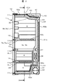
- FIG. 1 is a front view of a refrigerator showing the present embodiment
- FIG. 2 is a cross-sectional view taken along line AA of FIG.
- the refrigerator 1 of this embodiment has a refrigerator compartment 2 at the top and a vegetable compartment 5 at the bottom. Further, a lower freezer compartment 4 is provided between the refrigerator compartment 2 and the vegetable compartment 5. Between the lower freezer compartment 4 and the refrigerator compartment 2, an ice making room 3a and an upper freezer room 3b are provided side by side.
- Each door is provided with a door for opening and closing the front opening as shown in FIG.
- the refrigerating room 2 is provided with rotating refrigerating room doors 6a and 6b that rotate around the hinge 10 and the like.
- a drawer type ice making room door 7a, an upper freezing room door 7b, a lower freezing room door 8 and a vegetable room door 9 are arranged.
- these drawer type doors are pulled out, the storage containers housed in the respective storage chambers are pulled out together.
- Each door is provided with a seal member 11 for hermetically adhering to the main body of the refrigerator 1, and is attached to the outer peripheral edge of the door on the storage chamber side.
- a heat insulating partition 12 is arranged to insulate the refrigerator compartment 2 from the ice making chamber 3a and the upper freezer compartment 3b.
- the heat insulating partition 12 is a heat insulating wall having a thickness of about 30 to 50 mm, and is provided with a single material or a combination of a plurality of heat insulating materials such as a styrofoam, a foam heat insulating material (rigid urethane foam), and a vacuum heat insulating material. .
- a heat insulating partition 14 is provided between the lower freezer compartment 4 and the vegetable compartment 5 to insulate the compartment.
- a partition member 13 having a seal member 11 receiving surface is provided instead of a partition for heat insulation.
- insulation partitions are installed in the partitions of rooms with different storage temperature zones such as refrigeration and freezing.
- the storage room of the refrigerator compartment 2, the ice-making room 3a, the upper stage freezer compartment 3b, the lower stage freezer compartment 4, and the vegetable compartment 5 is each dividedly formed in the box 20, the arrangement
- the invention is not particularly limited to this.
- the refrigerator doors 6a and 6b, the ice making door 7a, the upper freezer door 7b, the lower freezer door 8, and the vegetable door 9 are also specifically limited, such as opening / closing by rotation, opening / closing by drawer, and the number of divided doors. It is not a thing.
- the box 20 includes an outer box 21 and an inner box 22, and a heat insulating part is provided in a space formed by the outer box 21 and the inner box 22 to insulate each storage chamber in the box 20 from the outside. Yes.
- a vacuum heat insulating material is disposed in the space between the outer box 21 and the inner box 22, and a space other than the vacuum heat insulating material is filled with a foam heat insulating material 23 such as hard urethane foam.
- the vacuum heat insulating material 50 will be described later.
- a cooler 28 is provided on the back side of the ice making room 3a, the upper freezing room 3b, and the lower freezing room 4 (freezing temperature zone room). Yes.
- the cooler 28 connects a compressor 30, a condenser 31, and a capillary tube (not shown) to constitute a refrigeration cycle.
- a blower 27 that circulates the cold air cooled by the cooler 28 in the refrigerator 1 and maintains a predetermined low temperature is disposed.
- the heat insulation partitions 12 and 14 which divide the refrigerator compartment 2, the ice making compartment 3a, the upper freezer compartment 3b, the freezer compartment 4 and the vegetable compartment 5 of the refrigerator 1 are provided with a polystyrene foam 33 and a vacuum heat insulating material 50c.
- foam heat insulating materials such as a rigid urethane foam, and it does not specifically limit to the foamed polystyrene 33 and the vacuum heat insulating material 50c.
- a concave portion 40 for accommodating an electrical component 41 such as a substrate for controlling the operation of the refrigerator 1 or a power supply substrate is formed in the rear portion of the top surface of the box 20.
- a cover 42 that covers the electrical component 41 is provided.
- the height of the cover 42 is arranged so as to be substantially the same height as the top surface 21a of the outer box 21 in consideration of appearance design and securing the internal volume. Although it does not specifically limit, when the height of the cover 42 protrudes from the top surface 21a of the outer box 21, it is desirable to keep in the range within 10 mm.
- the vacuum heat insulating material 50a is arrange
- the vacuum heat insulating material 50a is a single vacuum heat insulating material 50a formed in a substantially Z shape so as to straddle the lower part of the electrical component 41.
- the cover 42 is made of a steel plate in consideration of heat resistance.
- the compressor 30 and the condenser 31 arranged at the lower back of the box 20 are components that generate a large amount of heat. Therefore, a vacuum heat insulating material 50d is disposed on the projection surface toward the inner box 22 in order to prevent heat from entering the interior. Moreover, the heat insulation of the box 20 is improved by arranging the vacuum heat insulating material 50b and the like on the side surface 21e and the back surface 21b.
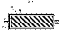
- the vacuum heat insulating material 50 includes a core material 51, an inner packaging material 52 for holding the core material 51 in a compressed state, and an outer jacket material 53 having a gas barrier layer covering the core material 51 held in a compressed state by the inner packaging material 52. And an adsorbent (not shown).
- the jacket material 53 is disposed outside the vacuum heat insulating material 50, and is configured in a bag shape in which portions of a certain width are bonded together by thermal welding from the ridgeline of the same size laminate film.
- the core material 51 is a laminate of flexible inorganic fibers that are not bonded or bound with a binder or the like, and glass wool having an average fiber diameter of 4 ⁇ m is used.
- the core material 51 is not particularly limited to this. For example, ceramic fibers, rock wool, Inorganic fibers such as glass fibers other than glass wool may be used.
- the inner packaging material 52 may be unnecessary.
- an organic resin fiber material can be used in addition to the inorganic fiber material.
- organic resin fibers there are no particular restrictions on use as long as the heat-resistant temperature is satisfied.
- polystyrene, polyethylene terephthalate, polypropylene, etc. are generally made into fibers so as to have a fiber diameter of about 1 to 30 ⁇ m by a melt blown method or a spunbond method. If it is a fiberization method, it will not ask in particular.
- the laminate structure of the jacket material 53 is not particularly limited as long as it has gas barrier properties and can be thermally welded.
- the surface protective layer, the multiple gas barrier layers, and the thermally welded layer are not limited.
- the laminate film has a three-layer structure.
- the surface protective layer is a resin film that serves as a protective material.
- the gas barrier layer has a layer in which a metal vapor deposition layer is provided on a resin film and a layer in which a metal vapor deposition layer is provided on a resin film having a high oxygen barrier property, and is bonded so that the metal vapor deposition layers face each other. .
- the heat welding layer uses a film having a low hygroscopicity like the surface layer.
- a biaxially stretched film such as polypropylene, polyamide, or polyethylene terephthalate is used as the surface protective layer.
- a biaxially stretched polyethylene terephthalate film with aluminum vapor deposition a biaxially stretched ethylene vinyl alcohol copolymer resin film with aluminum vapor deposition, a biaxially stretched polyvinyl alcohol resin film with aluminum vapor deposition, or an aluminum foil is used.
- heat-welding layer unstretched polyethylene and polypropylene films are used.
- the layer configuration and materials of the three-layer laminate film are not particularly limited to these.
- a gas barrier layer a metal foil or a resin-based film provided with a gas-barrier film made of an inorganic layered compound, a resin-based gas barrier coating material such as polyacrylic acid, DLC (diamond-like carbon), etc., or a heat-welded layer with oxygen
- a resin-based gas barrier coating material such as polyacrylic acid, DLC (diamond-like carbon), etc.
- a heat-welded layer with oxygen A polybutylene terephthalate film having a high barrier property may be used.
- the surface protective layer is a protective material for the gas barrier layer, but in order to improve the vacuum exhaust efficiency in the manufacturing process of the vacuum heat insulating material 50, it is preferable to dispose a resin having a low hygroscopic property.
- the resin barrier film other than the metal foil used for the gas barrier layer is significantly deteriorated in gas barrier properties due to moisture absorption, a resin having low hygroscopicity is also disposed in the heat welding layer. Thereby, while suppressing deterioration of gas barrier property, the moisture absorption amount of the whole laminate film is suppressed. Also, in the vacuum evacuation process of the vacuum heat insulating material 50, the amount of moisture brought into the jacket material 53 can be reduced, so that the vacuum evacuation efficiency is greatly improved, leading to higher performance of heat insulation performance.
- the lamination (bonding) of each film is generally performed by a dry laminating method via a two-component curable urethane adhesive, but the type of adhesive and the bonding method are particularly limited to this. However, other methods such as a wet laminating method and a thermal laminating method may be used.
- a heat-weldable polyethylene film and a physical adsorption type synthetic zeolite are used as the adsorbent.
- the inner packaging material 52 may be a polypropylene film, a polyethylene terephthalate film, a polybutylene terephthalate film, etc., as long as it has low hygroscopicity and can be thermally welded and has a small outgas.
- the agent adsorbs moisture and gas and may be either physical adsorption or chemical reaction type adsorption.
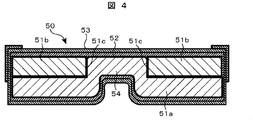
- FIG. 4 is a diagram illustrating a core material structure of a vacuum heat insulating material according to the first embodiment.
- the core material of the vacuum heat insulating material 50 is provided with a notch 51c in the first material 51b.
- a second material 51a having a density lower than that of the first material 51b and a large deformation rate in the thickness direction is overlaid on the first material 51b so that the second material 51a forms a recess 54. It is the structure curved to the notch part 51c side.
- the second material 51a is a glass wool fiber aggregate of inorganic fibers as a low density material that is largely deformed in the thickness direction.
- the first material 51b uses a polystyrene fiber aggregate of organic fibers as a high-density material with small deformation in the thickness direction.
- the first material 51b and the second material 51a are combined and vacuum-packed with the inner packaging material 52 and the outer jacket material 53, whereby the inside becomes a negative pressure, and the core material 51 receives the pressure equally from the outside.
- the first material 51b has a notch 51c, and the second material 51a having a lower density than the first material 51b is pushed into the notch 51c.
- the 1st material 51b can be made into the shape smaller than the 2nd material 51a, and the one end side or both ends side of the 2nd material 51a can curve, and can also comprise a recessed part.
- the maximum depth of the notch is made substantially the same as the thickness of the first material 51b after compression deformation.
- the curved portion of the second material 51a that is curved so as to form the recess 54 is substantially flush with one side surface of the first material 51b, and it is prevented from protruding more than necessary on the opposite side of the recess 54. be able to.
- FIG. 7 shows the examination results of the first material 51b and the second material 51a in this example, that is, the high-density material and the low-density material.
- ABS resin plate density 1050 kg / m 3 dense material was a low density material with glass wool fiber aggregate density 11.5 kg / m 3.
- a high density material was a polystyrene fiber aggregate having a density of 88 kg / m 3
- a low density material was a glass wool fiber aggregate having a density of 11.5 kg / m 3 .
- a high-density material was a polystyrene fiber aggregate having a density of 44 kg / m 3
- a low-density material was a glass wool fiber aggregate having a density of 11.5 kg / m 3 .
- high-density material was foamed urethane with a density of 25 kg / m 3 and low-density material was a glass wool fiber aggregate with a density of 11.5 kg / m 3 .
- a high-density material was a polystyrene fiber aggregate having a density of 44 kg / m 3
- a low-density material was a press-compressed glass wool fiber aggregate having a density of 23 kg / m 3 .
- a high-density material was a polystyrene fiber aggregate having a density of 16 kg / m 3
- a low-density material was a glass wool fiber aggregate having a density of 11.5 kg / m 3 .
- No. 7 was a glass wool fiber aggregate having a density of 11.5 kg / m 3 consisting of a high-density material and a low-density material.
- the recess shape has good moldability and a good value of thermal conductivity can be obtained.
- the density ratio of the low-density material to the high-density material is 26 to 52% (No. 3 to No. 5) to obtain a vacuum heat insulating material with better moldability and thermal conductivity. Can do.
- polystyrene fiber aggregate was used as the high-density material of this example, polyethylene terephthalate, polyethylene, polypropylene, polycarbonate, polyamide, polyvinyl alcohol fiber aggregate, foamed urethane, polystyrene, or the like can also be used. .
- the low-density material even in the same type of fiber assembly as the fiber assembly, it is possible to form a concave shape by using a material having a different density such as a binder or a glass wool sheet.
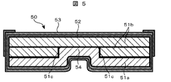
- Example 2 Next, Example 2 will be described with reference to FIG.
- a part of the first material 51b polystyrene fiber aggregate
- the second material 51a glass wool fiber aggregate. That is, it is the structure which provided the clearance gap of the predetermined space
- the size of the concave portion 54 of the second material 51a is determined by the thickness of the first material 51b, the size of the concave portion 54 can be easily changed by reducing the thickness of the layer of the first material 51b. be able to. Thereby, in the layer of the second material 51a, it is possible to form a small concave portion 54 that is difficult to be formed by a spring back by pressing or the like.
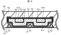
- FIG. 6 is a cross-sectional view when the vacuum heat insulating material 50 is installed between the outer box 21 and the inner box 22 of the refrigerator.
- a vacuum heat insulating material 50 is provided between the outer box 21 and the inner box 22.
- the heat radiating pipe 60 for radiating the refrigerant is disposed between the outer box 21 and the vacuum heat insulating material 50 so as to contact the outer box 21 made of steel plate. Thereby, since the heat from the heat radiating pipe 60 is transmitted to the outside through the outer casing 21 made of a steel plate, it can be suppressed so as not to affect the inside of the cabinet.
- the heat radiating pipe 60 is installed in the recess 54.
- the heat radiating pipe 60 can be arranged in the flat outer box 21 and the vacuum heat insulating material 50 can be installed so as to cover the heat radiating pipe 60.
- the vacuum heat insulating material 50 can be installed from above the heat radiating pipe 60 without grooving the outer box 21 or the like. Therefore, since the vacuum heat insulating material 50 can be arranged with a large outer diameter along the outer box 21, the coverage by the vacuum heat insulating material 50 is increased, and the refrigerator 1 with improved heat insulating performance with less heat leakage can be provided. .
- the core material is provided with a notch in the first material, and the second material having a lower density and a higher deformation rate in the thickness direction than the first material is used as the first material.
- the second material is characterized by being curved toward the notch portion so as to form a recess. That is, the second material that is largely deformed in the thickness direction becomes a shape along the notch portion of the first material due to the pressure from the outside air when vacuum packaging is performed, and a recess can be provided.
Abstract
Description
次に、本発明の実施例1について図4を参照しながら説明する。
次に、図5を参照して実施例2について説明する。図5は、第一の材料51b(ポリスチレン繊維集合体)の一部の層を、第二の材料51a(グラスウール繊維集合体)の大きさよりも小さくしたものである。すなわち、第二の材料51aと重なる第一の材料51bの層に、所定間隔の隙間を設けた構成である。または、第二の材料51aと重なる第一の材料51bの層に、第一の材料51bの圧縮変形後の厚さとほぼ同一の切り欠き部を設けた構成とする。
次に、図6を参照して実施例3について説明する。図6は、冷蔵庫の外箱21と内箱22との間に、真空断熱材50を設置した時の断面図である。外箱21と内箱22との間には、真空断熱材50を備えている。さらに、冷媒を放熱する放熱パイプ60が、鋼板製の外箱21に接するように、外箱21と真空断熱材50との間に配置している。これにより、放熱パイプ60からの熱が鋼板製の外箱21を伝わって外部に放熱されるので、庫内に熱影響が及ばないように抑制できる。
20 箱体
21 外箱
22 内箱
23 発泡断熱材
40,54 凹部
50,50a,50b,50c,50d 真空断熱材
51 芯材
51a 第二の材料(グラスウール繊維集合体)
51b 第一の材料(ポリスチレン繊維集合体)
51c 切り欠き部
52 内包材
53 外被材
60 放熱パイプ
61 アルミテープ
62 発泡ウレタン。
Claims (6)
- 芯材と、該芯材を収納して内部を減圧する外被材とを備えた真空断熱材において、
前記芯材は第一の材料に切り欠き部を設け、該第一の材料よりも密度が低く厚み方向の変形率が大きい第二の材料を前記第一の材料の上に重ねて、前記第二の材料は凹部を形成するように前記切り欠き部側に湾曲したことを特徴とする真空断熱材。 - 前記第二の材料としてグラスウール又は樹脂繊維集合体を用いることを特徴とする、請求項1記載の真空断熱材。
- 前記第一の材料として樹脂繊維集合体又は発泡ウレタンを用いることを特徴とする、請求項1記載の真空断熱材。
- 前記第一の材料に対する前記第二の材料の密度比は13~72%であることを特徴とする、請求項1乃至3のいずれかに記載の真空断熱材。
- 前記切り欠き部の最大深さは、前記第一の材料の圧縮変形後の厚さとほぼ同一となることを特徴とする、請求項1乃至3のいずれかに記載の真空断熱材。
- 外箱と内箱との間に真空断熱材を備え、
冷媒を放熱する放熱パイプを外箱と真空断熱材との間に配置した冷蔵庫において、
前記真空断熱材は、芯材と、該芯材を収納して内部を減圧する外被材とを備え、
前記芯材は第一の材料に切り欠き部を設け、該第一の材料よりも密度が低く厚み方向の変形率が大きい第二の材料を前記第一の材料の上に重ねて、前記第二の材料は凹部を形成するように前記切り欠き部側に湾曲して、
前記凹部に前記放熱パイプが位置することを特徴とする冷蔵庫。
Priority Applications (2)
| Application Number | Priority Date | Filing Date | Title |
|---|---|---|---|
| CN201080067854.1A CN102971571B (zh) | 2010-07-06 | 2010-08-24 | 真空绝热材料以及使用了该真空绝热材料的冰箱 |
| KR1020127032150A KR101495127B1 (ko) | 2010-07-06 | 2010-08-24 | 진공 단열재 및 그것을 사용한 냉장고 |
Applications Claiming Priority (2)
| Application Number | Priority Date | Filing Date | Title |
|---|---|---|---|
| JP2010153542A JP5492685B2 (ja) | 2010-07-06 | 2010-07-06 | 真空断熱材及びそれを用いた冷蔵庫 |
| JP2010-153542 | 2010-07-06 |
Publications (1)
| Publication Number | Publication Date |
|---|---|
| WO2012004901A1 true WO2012004901A1 (ja) | 2012-01-12 |
Family
ID=45440897
Family Applications (1)
| Application Number | Title | Priority Date | Filing Date |
|---|---|---|---|
| PCT/JP2010/064293 WO2012004901A1 (ja) | 2010-07-06 | 2010-08-24 | 真空断熱材及びそれを用いた冷蔵庫 |
Country Status (4)
| Country | Link |
|---|---|
| JP (1) | JP5492685B2 (ja) |
| KR (1) | KR101495127B1 (ja) |
| CN (1) | CN102971571B (ja) |
| WO (1) | WO2012004901A1 (ja) |
Cited By (2)
| Publication number | Priority date | Publication date | Assignee | Title |
|---|---|---|---|---|
| CN113272610A (zh) * | 2019-01-07 | 2021-08-17 | 东芝生活电器株式会社 | 冰箱 |
| EP4166876A1 (en) * | 2020-10-30 | 2023-04-19 | Whirlpool Corporation | Insulation materials for a vacuum insulated structure and methods of forming |
Families Citing this family (14)
| Publication number | Priority date | Publication date | Assignee | Title |
|---|---|---|---|---|
| KR101280776B1 (ko) * | 2010-09-14 | 2013-07-05 | 히타치 어플라이언스 가부시키가이샤 | 진공 단열재 및 이것을 이용한 냉장고 |
| JPWO2014122939A1 (ja) * | 2013-02-07 | 2017-01-26 | パナソニックIpマネジメント株式会社 | 断熱パネル |
| CN104373750A (zh) * | 2013-08-12 | 2015-02-25 | 苏州维艾普新材料股份有限公司 | 一种叠层的vip玻璃纤维芯材 |
| CN104373752A (zh) * | 2013-08-12 | 2015-02-25 | 苏州维艾普新材料股份有限公司 | 一种包裹真空绝热板的低密度发泡材料 |
| CN104373751A (zh) * | 2013-08-12 | 2015-02-25 | 苏州维艾普新材料股份有限公司 | 一种长径比差异的vip玻璃纤维芯材 |
| KR101431663B1 (ko) * | 2013-12-11 | 2014-08-20 | 주식회사 티에스시 | 단열구조 및 이를 포함하는 배관용 히터 |
| KR102529852B1 (ko) * | 2015-08-03 | 2023-05-08 | 엘지전자 주식회사 | 진공단열체 및 냉장고 |
| WO2017033313A1 (ja) * | 2015-08-26 | 2017-03-02 | 三菱電機株式会社 | 真空断熱材および冷蔵庫 |
| JP2018017314A (ja) * | 2016-07-28 | 2018-02-01 | 日立アプライアンス株式会社 | 真空断熱材及びそれを用いた冷蔵庫 |
| KR20210006698A (ko) * | 2019-07-09 | 2021-01-19 | 엘지전자 주식회사 | 진공단열체 및 냉장고 |
| JP7407588B2 (ja) * | 2019-12-20 | 2024-01-04 | 東芝ライフスタイル株式会社 | 断熱材の製造方法、及び冷蔵庫の製造方法 |
| CN114174195B (zh) * | 2019-12-26 | 2023-07-04 | 松下知识产权经营株式会社 | 恒温容器 |
| KR20220163653A (ko) | 2021-06-03 | 2022-12-12 | 엘지전자 주식회사 | 냉장고 |
| KR102554173B1 (ko) * | 2023-03-13 | 2023-07-11 | (주)이플러스 | 단열 냉동 창고 시스템 |
Citations (4)
| Publication number | Priority date | Publication date | Assignee | Title |
|---|---|---|---|---|
| JP2004011755A (ja) * | 2002-06-06 | 2004-01-15 | Matsushita Refrig Co Ltd | 真空断熱材及びその製造方法、並びに真空断熱材を用いた断熱箱体 |
| JP2005016629A (ja) * | 2003-06-26 | 2005-01-20 | Nisshinbo Ind Inc | 真空断熱材及びその製造方法 |
| JP2005036975A (ja) * | 2003-06-27 | 2005-02-10 | Matsushita Electric Ind Co Ltd | 断熱材と、その製造方法、及びその断熱材を使用した機器 |
| JP2008064323A (ja) * | 2006-09-04 | 2008-03-21 | Sharp Corp | 真空断熱パネル及びそれを用いた冷蔵庫 |
Family Cites Families (4)
| Publication number | Priority date | Publication date | Assignee | Title |
|---|---|---|---|---|
| TW470837B (en) * | 2000-04-21 | 2002-01-01 | Matsushita Refrigeration | Vacuum heat insulator |
| JP2006292063A (ja) | 2005-04-11 | 2006-10-26 | Matsushita Electric Ind Co Ltd | 真空断熱材構成 |
| JP4897473B2 (ja) * | 2006-12-26 | 2012-03-14 | 倉敷紡績株式会社 | 真空断熱材 |
| JP2009063064A (ja) * | 2007-09-06 | 2009-03-26 | Hitachi Appliances Inc | 真空断熱材及びこれを用いた冷蔵庫 |
-
2010
- 2010-07-06 JP JP2010153542A patent/JP5492685B2/ja active Active
- 2010-08-24 WO PCT/JP2010/064293 patent/WO2012004901A1/ja active Application Filing
- 2010-08-24 CN CN201080067854.1A patent/CN102971571B/zh active Active
- 2010-08-24 KR KR1020127032150A patent/KR101495127B1/ko not_active IP Right Cessation
Patent Citations (4)
| Publication number | Priority date | Publication date | Assignee | Title |
|---|---|---|---|---|
| JP2004011755A (ja) * | 2002-06-06 | 2004-01-15 | Matsushita Refrig Co Ltd | 真空断熱材及びその製造方法、並びに真空断熱材を用いた断熱箱体 |
| JP2005016629A (ja) * | 2003-06-26 | 2005-01-20 | Nisshinbo Ind Inc | 真空断熱材及びその製造方法 |
| JP2005036975A (ja) * | 2003-06-27 | 2005-02-10 | Matsushita Electric Ind Co Ltd | 断熱材と、その製造方法、及びその断熱材を使用した機器 |
| JP2008064323A (ja) * | 2006-09-04 | 2008-03-21 | Sharp Corp | 真空断熱パネル及びそれを用いた冷蔵庫 |
Cited By (3)
| Publication number | Priority date | Publication date | Assignee | Title |
|---|---|---|---|---|
| CN113272610A (zh) * | 2019-01-07 | 2021-08-17 | 东芝生活电器株式会社 | 冰箱 |
| EP4166876A1 (en) * | 2020-10-30 | 2023-04-19 | Whirlpool Corporation | Insulation materials for a vacuum insulated structure and methods of forming |
| US11692763B2 (en) | 2020-10-30 | 2023-07-04 | Whirlpool Corporation | Insulation materials for a vacuum insulated structure and methods of forming |
Also Published As
| Publication number | Publication date |
|---|---|
| JP5492685B2 (ja) | 2014-05-14 |
| CN102971571B (zh) | 2015-09-23 |
| CN102971571A (zh) | 2013-03-13 |
| JP2012017752A (ja) | 2012-01-26 |
| KR20130018919A (ko) | 2013-02-25 |
| KR101495127B1 (ko) | 2015-02-24 |
Similar Documents
| Publication | Publication Date | Title |
|---|---|---|
| JP5492685B2 (ja) | 真空断熱材及びそれを用いた冷蔵庫 | |
| JP4695663B2 (ja) | 冷蔵庫 | |
| JP5544338B2 (ja) | 真空断熱材及びこれを用いた冷蔵庫 | |
| JP2012063029A (ja) | 真空断熱材及びそれを用いた冷蔵庫 | |
| JP2001165557A (ja) | 冷蔵庫 | |
| JP2013002484A (ja) | 真空断熱材及びそれを用いた冷蔵庫 | |
| JP2009024922A (ja) | 冷蔵庫 | |
| JP5372877B2 (ja) | 真空断熱材及びそれを用いた冷蔵庫 | |
| JP2010276308A (ja) | 真空断熱材を備えた冷蔵庫 | |
| JP2013061131A (ja) | 真空断熱材を備えた冷蔵庫 | |
| JP2013119878A (ja) | 真空断熱材用芯材、その真空断熱材用芯材を有する真空断熱材及びその真空断熱材を適用した冷蔵庫 | |
| JP5401258B2 (ja) | 冷蔵庫 | |
| JP2011099566A (ja) | 真空断熱パネル及び冷蔵庫 | |
| JP2016080281A (ja) | 断熱箱体及び断熱扉 | |
| JP2009024921A (ja) | 冷蔵庫 | |
| JP5571610B2 (ja) | 真空断熱材の製造方法、真空断熱材及びこれを備えた冷蔵庫 | |
| JP2013053722A (ja) | 真空断熱材及びこれを用いた断熱機器 | |
| JP2013024440A (ja) | 冷蔵庫 | |
| JP2013040717A (ja) | 真空断熱材及びそれを用いた冷蔵庫 | |
| JP2012026583A (ja) | 冷蔵庫 | |
| JP5401422B2 (ja) | 真空断熱材及びこれを用いた冷蔵庫 | |
| JP2012026622A (ja) | 真空断熱材及びこれを用いた冷蔵庫 | |
| JP2012229849A (ja) | 冷蔵庫および冷凍庫 | |
| JP2013002580A (ja) | 真空断熱材及びそれを用いた冷蔵庫 | |
| JP5982276B2 (ja) | 真空断熱材及び真空断熱材を用いた冷蔵庫 |
Legal Events
| Date | Code | Title | Description |
|---|---|---|---|
| WWE | Wipo information: entry into national phase |
Ref document number: 201080067854.1 Country of ref document: CN |
|
| 121 | Ep: the epo has been informed by wipo that ep was designated in this application |
Ref document number: 10854454 Country of ref document: EP Kind code of ref document: A1 |
|
| ENP | Entry into the national phase |
Ref document number: 20127032150 Country of ref document: KR Kind code of ref document: A |
|
| NENP | Non-entry into the national phase |
Ref country code: DE |
|
| 122 | Ep: pct application non-entry in european phase |
Ref document number: 10854454 Country of ref document: EP Kind code of ref document: A1 |