WO2012002179A1 - 車両用操舵装置 - Google Patents
車両用操舵装置 Download PDFInfo
- Publication number
- WO2012002179A1 WO2012002179A1 PCT/JP2011/063958 JP2011063958W WO2012002179A1 WO 2012002179 A1 WO2012002179 A1 WO 2012002179A1 JP 2011063958 W JP2011063958 W JP 2011063958W WO 2012002179 A1 WO2012002179 A1 WO 2012002179A1
- Authority
- WO
- WIPO (PCT)
- Prior art keywords
- steering
- reaction force
- target
- vehicle
- target steering
- Prior art date
- Legal status (The legal status is an assumption and is not a legal conclusion. Google has not performed a legal analysis and makes no representation as to the accuracy of the status listed.)
- Ceased
Links
Images


Classifications
-
- B—PERFORMING OPERATIONS; TRANSPORTING
- B62—LAND VEHICLES FOR TRAVELLING OTHERWISE THAN ON RAILS
- B62D—MOTOR VEHICLES; TRAILERS
- B62D6/00—Arrangements for automatically controlling steering depending on driving conditions sensed and responded to, e.g. control circuits
-
- B—PERFORMING OPERATIONS; TRANSPORTING
- B62—LAND VEHICLES FOR TRAVELLING OTHERWISE THAN ON RAILS
- B62D—MOTOR VEHICLES; TRAILERS
- B62D6/00—Arrangements for automatically controlling steering depending on driving conditions sensed and responded to, e.g. control circuits
- B62D6/008—Control of feed-back to the steering input member, e.g. simulating road feel in steer-by-wire applications
Definitions
- the present invention relates to the technical field of vehicle steering devices.
- a target steering reaction force (or “target steering torque”) to be applied to the steering handle is set based on the steering angle and the vehicle speed, and this target steering reaction force is applied to the steering handle.
- Electric power steering (EPS: Electric Power Steering) that performs force control is known (for example, see Patent Document 1). By performing such reaction force control, the driver's steering feeling can be improved.
- Patent Documents 2 and 3 exist as prior art documents related to the present invention.
- the present invention has been made in view of the above-described problems, for example, and an object of the present invention is to provide a vehicle steering apparatus that can improve the steering feeling of the driver.
- a first vehicle steering apparatus sets a target steering reaction force to be applied to a steering wheel based on a steering angle and a vehicle speed, and applies the target steering reaction force.
- a vehicle steering apparatus that performs force control, the steering speed specifying means for specifying the steering speed of the steering handle, and the target steering according to the magnitude of the absolute value of the steering speed specified by the steering speed specifying means
- Target steering reaction force changing means for changing the magnitude of the reaction force.
- the target steering reaction force (that is, the target value of the steering reaction force to be applied to the steering wheel) is set based on the steering angle and the vehicle speed, and the reaction force control is performed.
- a target steering reaction force is applied to the steering wheel.
- the target steering reaction force changing means changes the magnitude of the target steering reaction force according to the magnitude of the absolute value of the steering speed specified by the steering speed specifying means.
- the driver's steering feeling can be improved as compared with a case where the magnitude of the target steering reaction force is constant regardless of the magnitude of the absolute value of the steering speed.
- the target steering reaction force changing means has a predetermined state in which the magnitude of the absolute value of the steering speed specified by the steering speed specifying means is not more than a threshold value.
- the magnitude of the target steering reaction force is changed so as to be smaller than the currently set magnitude of the target steering reaction force.
- the second vehicle steering apparatus sets a target steering reaction force to be applied to the steering wheel based on the steering angle and the vehicle speed, and applies the target steering reaction force.
- a vehicle steering apparatus that performs force control, wherein the target steering reaction force is different in magnitude when the steering handle is in a holding state and when the steering handle is not in a holding state.
- a target steering reaction force setting means for setting a steering reaction force is provided.
- the target steering reaction force is set based on the steering angle and the vehicle speed, and the target steering reaction force is applied to the steering handle by reaction force control.
- the target steering reaction force setting means is configured so that the magnitude of the target steering reaction force is different between when the steering handle is in the holding state and when the steering handle is not in the holding state.
- the target steering reaction force setting means maintains the magnitude of the target steering torque at the first magnitude appropriate for improving the steering feeling when the steering handle is in the steering-holding state. In the case of not being in the rudder state, switching is performed with the second size appropriate for improving the steering feeling.
- the driver's steering feeling is improved as compared with the case where the magnitude of the target steering reaction force is the same when the steering handle is in the holding state and when the steering handle is not in the holding state. Can do.
- the target steering reaction force setting means is more effective when the steering handle is in a holding state than when the steering handle is not in a holding state.
- the target steering reaction force is set so that the magnitude of the target steering reaction force is reduced.
- the steering feeling of the driver when the steering handle is in the steering holding state can be improved more reliably.
- FIG. 1 is a block diagram illustrating an overall configuration of a vehicle including a vehicle steering apparatus according to an embodiment of the present invention. It is a block diagram which shows notionally the structure of the controller which concerns on one Embodiment of this invention. It is a flowchart which shows the flow of the setting of the target steering reaction force in the reaction force control which concerns on one Embodiment of this invention. It is a map which prescribes
- FIG. 1 is a block diagram illustrating an overall configuration of a vehicle including a vehicle steering apparatus according to the present embodiment.
- a vehicle 10 including a vehicle steering apparatus includes a steering wheel 11, a steering shaft 12, a motor 13, a rack and pinion portion 14, a tie rod 15, a knuckle arm 16, A wheel 17, a steering angle sensor 21, a torque sensor 22, a vehicle speed sensor 23, and a controller 100 are provided.
- Steering wheel 11 (hereinafter simply referred to as “steering 11” as appropriate) is an example of a “steering handle” according to the present invention, and is operated by a driver to turn vehicle 10 or the like.
- the steering 11 is connected to the rack and pinion unit 14 via the steering shaft 12.
- the steering shaft 12 is provided with a steering angle sensor 21, a torque sensor 22 and a motor 13.
- the steering angle sensor 21 detects a steering angle corresponding to the operation of the steering wheel 11 by the driver.
- the steering angle sensor 21 supplies a detection signal corresponding to the detected steering angle to the controller 100.
- the torque sensor 22 detects torque acting on the steering shaft 12.
- the torque sensor 22 supplies a detection signal corresponding to the detected torque to the controller 100.
- the vehicle speed sensor 23 detects the vehicle speed of the vehicle 10 and supplies a detection signal corresponding to the detected vehicle speed to the controller 100.
- the motor 13 is configured by a reduction gear, an electric motor, or the like, and applies torque to the steering shaft 12 under the control of the controller 100.
- assist torque the torque that the motor 13 applies to the steering shaft 12 is appropriately referred to as “assist torque”.
- the rack and pinion unit 14 is composed of a rack and a pinion, and operates by receiving rotation from the steering shaft 12.
- a tie rod 15 and a knuckle arm 16 are connected to the rack and pinion unit 14, and wheels 17 are connected to the knuckle arm 16. In this case, when the tie rod 15 and the knuckle arm 16 are operated by the rack and pinion unit 14, the wheel 17 connected to the knuckle arm 16 is steered.
- the controller 100 is an electronic control unit including a CPU (Central Processing Unit), a ROM (Read Only Memory), a RAM (Random Access Memory), and the like.
- the controller 100 is a reaction force control that controls the motor 13 so that a target steering reaction force is applied to the steering 11 based on detection signals supplied from the steering angle sensor 21, the torque sensor 22, and the vehicle speed sensor 23. I do. That is, in the reaction force control, the assist torque that the motor 13 applies to the steering shaft 12 is controlled by the controller 100 so that the target steering reaction force is applied to the steering 11.
- FIG. 2 is a block diagram conceptually showing the configuration of the controller 100.
- the controller 100 includes a target steering reaction force setting unit 110, a steering speed specifying unit 120, and a steering determination unit 130.
- the target steering reaction force setting unit 110 is an example of the “target steering reaction force setting unit” in the second vehicle steering apparatus according to the present invention, and the “target steering reaction force setting unit” in the first vehicle steering apparatus according to the present invention. It functions as an example of “target steering reaction force changing means”.
- the steering speed specifying unit 120 specifies the steering speed at which the steering 11 is steered based on the detection signal supplied from the steering angle sensor 21. Specifically, the steering speed specifying unit 120 specifies the steering speed of the steering wheel 11 by calculating a temporal change in the steering angle detected by the steering sensor 21.
- the steering holding determination unit 130 determines whether or not the steering 11 is in the steering holding state. Specifically, the steering determination unit 130 determines that the steering angle is equal to or greater than the steering angle threshold based on the steering angle detected by the steering angle sensor 21 and the steering speed specified by the steering speed specifying unit 120, and When the state where the absolute value of the speed is equal to or less than the steering speed threshold continues for the first predetermined time or more, it is determined that the steering 11 is in the holding state, and other states (that is, the steering angle is the steering angle). When the state smaller than the angle threshold value or the state where the absolute value of the steering speed is larger than the steering speed threshold value) continues for the second predetermined time or longer, the steering 11 is in a normal state that is not in the holding state. judge.
- the target steering reaction force setting unit 110 sets a target steering reaction force to be applied to the steering 11 based on detection signals supplied from the steering angle sensor 21 and the vehicle speed sensor 23. More specifically, the target steering reaction force setting unit 110 sets a target steering reaction force to be applied to the steering 11 based on a target steering reaction force map described later with reference to FIGS. 4 and 5.
- the target steering reaction force map is stored in the ROM or RAM of the controller 100.
- reaction force control by the vehicle steering apparatus according to the present embodiment will be described with reference to FIG.
- setting of the target steering reaction force when the vehicle steering apparatus according to the present embodiment performs the reaction force control will be mainly described.
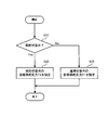
- FIG. 3 is a flowchart showing a flow of setting the target steering reaction force in the reaction force control.
- step S10 in the reaction force control, first, it is determined by the steering determination unit 130 (see FIG. 2) whether or not the steering wheel 11 is in the steering state (step S10).
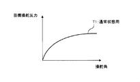
- the target steering reaction force setting unit 110 is for a normal state as shown in the graph shown in FIG.
- the target steering reaction force T1 for the normal state is set as the target steering reaction force to be applied to the steering 11 (step S30).
- the target steering reaction force map for the normal state is a map that defines the target steering reaction force when the steering 11 is in the normal state according to the steering angle and the vehicle speed.
- FIG. 4 shows only the relationship between the steering angle and the target steering reaction force in the target steering reaction force map for the normal state, and does not show the relationship between the vehicle speed and the target steering reaction force.
- the target steering reaction force determination unit 110 displays the target for the holding state as shown by the solid line in FIG. Based on the steering reaction force map, the target steering reaction force T2 for the steered state is set as the target steering reaction force to be applied to the steering 11 (step S20).
- the target steering reaction force map for the holding state is a map that regulates the target steering reaction force when the steering 11 is in the holding state according to the steering angle and the vehicle speed. In FIG. 5, only the relationship between the steering angle and the target steering reaction force in the target steering reaction force map for the steered state is shown, and the relationship between the vehicle speed and the target steering reaction force is not shown.
- the magnitude of the target steering reaction force T2 for the steered state is smaller than the magnitude of the target steering reaction force T1 for the normal state.
- the target steering reaction force setting unit 110 has a target steering reaction force that is greater when the steering 11 is in the holding state (step S10: Yes) than when the steering 11 is in the normal state (step S10: No).
- the target steering reaction force is set so that the size becomes smaller.
- the target steering reaction force setting unit 110 has a target steering reaction force to be applied to the steering 11 that is larger than the target steering reaction force T1 for the normal state and the target steering reaction force T1 for the normal state. Switching between the target steering reaction force T2 for a small steering holding state. Therefore, it is possible to reduce the steering reaction force that is unnecessary for the driver who is keeping the steering wheel 11 in the steered state, and to reliably improve the steering feeling of the driver in the steered state.
- the case where the magnitude of the target steering reaction force T2 for the steered state is smaller than the magnitude of the target steering reaction force T1 for the normal state has been described as an example.
- the magnitude of the steering reaction force T2 may be larger than the magnitude of the target steering reaction force T1 for the normal state.
- steering reaction forces having different magnitudes can be applied to the steering 11 when the steering 11 is in the normal state and when the steering 11 is in the holding state. The ring can be improved.
- the steering speed specifying unit 120 specifies the target steering reaction force.
- the magnitude of the target steering reaction force may be changed according to the magnitude of the absolute value of the steering speed. If comprised in this way, a driver
Landscapes
- Engineering & Computer Science (AREA)
- Chemical & Material Sciences (AREA)
- Combustion & Propulsion (AREA)
- Transportation (AREA)
- Mechanical Engineering (AREA)
- Steering Control In Accordance With Driving Conditions (AREA)
- Power Steering Mechanism (AREA)
Abstract
Description
Claims (4)
- 操舵ハンドルに付与すべき目標操舵反力を操舵角及び車速に基づいて設定し、前記目標操舵反力を付与する反力制御を行う車両用操舵装置であって、
前記操舵ハンドルの操舵速度を特定する操舵速度特定手段と、
該操舵速度特定手段によって特定された操舵速度の絶対値の大きさに応じて前記目標操舵反力の大きさを変更する目標操舵反力変更手段と
を備えることを特徴とする車両用操舵装置。 - 前記目標操舵反力変更手段は、前記操舵速度特定手段によって特定された操舵速度の絶対値の大きさが閾値以下である状態が所定期間以上継続する場合には、前記目標操舵反力の大きさを、現在設定されている前記目標操舵反力の大きさよりも小さくなるように変更する請求項1に記載の車両用操舵装置。
- 操舵ハンドルに付与すべき目標操舵反力を操舵角及び車速に基づいて設定し、前記目標操舵反力を付与する反力制御を行う車両用操舵装置であって、
前記操舵ハンドルが保舵状態である場合と前記操舵ハンドルが保舵状態でない場合とで前記目標操舵反力の大きさが互いに異なるように、前記目標操舵反力を設定する目標操舵反力設定手段を備えることを特徴とする車両用操舵装置。 - 前記目標操舵反力設定手段は、前記操舵ハンドルが保舵状態である場合には、前記操舵ハンドルが保舵状態でない場合よりも前記目標操舵反力の大きさが小さくなるように、前記目標操舵反力を設定する請求項3に記載の車両用操舵装置。
Priority Applications (2)
| Application Number | Priority Date | Filing Date | Title |
|---|---|---|---|
| CN2011800313392A CN102958783A (zh) | 2010-06-30 | 2011-06-17 | 车辆用转向装置 |
| US13/807,094 US20130103262A1 (en) | 2010-06-30 | 2011-06-17 | Vehicle steering apparatus |
Applications Claiming Priority (2)
| Application Number | Priority Date | Filing Date | Title |
|---|---|---|---|
| JP2010149048A JP5221600B2 (ja) | 2010-06-30 | 2010-06-30 | 車両用操舵装置 |
| JP2010-149048 | 2010-06-30 |
Publications (1)
| Publication Number | Publication Date |
|---|---|
| WO2012002179A1 true WO2012002179A1 (ja) | 2012-01-05 |
Family
ID=45401901
Family Applications (1)
| Application Number | Title | Priority Date | Filing Date |
|---|---|---|---|
| PCT/JP2011/063958 Ceased WO2012002179A1 (ja) | 2010-06-30 | 2011-06-17 | 車両用操舵装置 |
Country Status (4)
| Country | Link |
|---|---|
| US (1) | US20130103262A1 (ja) |
| JP (1) | JP5221600B2 (ja) |
| CN (1) | CN102958783A (ja) |
| WO (1) | WO2012002179A1 (ja) |
Cited By (1)
| Publication number | Priority date | Publication date | Assignee | Title |
|---|---|---|---|---|
| US8855863B2 (en) | 2010-07-09 | 2014-10-07 | Toyota Jidosha Kabushiki Kaisha | Vehicle steering apparatus |
Families Citing this family (2)
| Publication number | Priority date | Publication date | Assignee | Title |
|---|---|---|---|---|
| JP5821659B2 (ja) | 2011-12-22 | 2015-11-24 | トヨタ自動車株式会社 | 車両用操舵装置 |
| EP2985207B1 (en) * | 2013-04-08 | 2018-05-23 | Mitsubishi Electric Corporation | Steering control device, and steering control method |
Citations (5)
| Publication number | Priority date | Publication date | Assignee | Title |
|---|---|---|---|---|
| JPH05105100A (ja) * | 1991-09-27 | 1993-04-27 | Honda Motor Co Ltd | 車両の操舵装置 |
| JPH06127413A (ja) * | 1992-10-19 | 1994-05-10 | Toyota Motor Corp | 車速感応型電動式パワーステアリング装置 |
| JP2005081986A (ja) * | 2003-09-08 | 2005-03-31 | Favess Co Ltd | 電動パワーステアリング装置 |
| JP2006027301A (ja) * | 2004-07-12 | 2006-02-02 | Honda Motor Co Ltd | 反力制御装置 |
| JP2006137215A (ja) * | 2004-11-10 | 2006-06-01 | Toyota Motor Corp | ステアバイワイヤ式ステアリング装置の操舵反力制御装置 |
Family Cites Families (6)
| Publication number | Priority date | Publication date | Assignee | Title |
|---|---|---|---|---|
| JP2780114B2 (ja) * | 1989-07-17 | 1998-07-30 | ジェイエスアール株式会社 | 液状硬化性樹脂組成物の製造方法 |
| JP3525969B2 (ja) * | 1995-12-01 | 2004-05-10 | 本田技研工業株式会社 | 電動パワーステアリング装置 |
| JP2007269062A (ja) * | 2006-03-30 | 2007-10-18 | Honda Motor Co Ltd | 車両用操舵装置 |
| JP2007333657A (ja) * | 2006-06-19 | 2007-12-27 | Toyota Motor Corp | 操舵角検出装置 |
| JP4329859B2 (ja) * | 2007-12-12 | 2009-09-09 | トヨタ自動車株式会社 | 操舵制御装置 |
| CN101434259A (zh) * | 2008-12-11 | 2009-05-20 | 奇瑞汽车股份有限公司 | 一种自适应转向系统及其控制方法 |
-
2010
- 2010-06-30 JP JP2010149048A patent/JP5221600B2/ja not_active Expired - Fee Related
-
2011
- 2011-06-17 US US13/807,094 patent/US20130103262A1/en not_active Abandoned
- 2011-06-17 WO PCT/JP2011/063958 patent/WO2012002179A1/ja not_active Ceased
- 2011-06-17 CN CN2011800313392A patent/CN102958783A/zh active Pending
Patent Citations (5)
| Publication number | Priority date | Publication date | Assignee | Title |
|---|---|---|---|---|
| JPH05105100A (ja) * | 1991-09-27 | 1993-04-27 | Honda Motor Co Ltd | 車両の操舵装置 |
| JPH06127413A (ja) * | 1992-10-19 | 1994-05-10 | Toyota Motor Corp | 車速感応型電動式パワーステアリング装置 |
| JP2005081986A (ja) * | 2003-09-08 | 2005-03-31 | Favess Co Ltd | 電動パワーステアリング装置 |
| JP2006027301A (ja) * | 2004-07-12 | 2006-02-02 | Honda Motor Co Ltd | 反力制御装置 |
| JP2006137215A (ja) * | 2004-11-10 | 2006-06-01 | Toyota Motor Corp | ステアバイワイヤ式ステアリング装置の操舵反力制御装置 |
Cited By (1)
| Publication number | Priority date | Publication date | Assignee | Title |
|---|---|---|---|---|
| US8855863B2 (en) | 2010-07-09 | 2014-10-07 | Toyota Jidosha Kabushiki Kaisha | Vehicle steering apparatus |
Also Published As
| Publication number | Publication date |
|---|---|
| JP2012011861A (ja) | 2012-01-19 |
| JP5221600B2 (ja) | 2013-06-26 |
| CN102958783A (zh) | 2013-03-06 |
| US20130103262A1 (en) | 2013-04-25 |
Similar Documents
| Publication | Publication Date | Title |
|---|---|---|
| JP5135722B2 (ja) | 車両用操舵装置 | |
| EP2604489B1 (en) | Vehicle steering system | |
| JP5365607B2 (ja) | 操舵装置 | |
| JP5131324B2 (ja) | 車両用操舵装置 | |
| JP5037156B2 (ja) | 電動パワーステアリング装置 | |
| US8972113B2 (en) | Electric power steering system | |
| JP2007253640A (ja) | 操舵装置および操舵制御方法 | |
| KR20120137032A (ko) | 전동식 동력 조향장치의 제어방법 | |
| JP4579056B2 (ja) | 車両用操舵装置 | |
| JP5221600B2 (ja) | 車両用操舵装置 | |
| KR20140044711A (ko) | 전동식 조향장치의 모터 구동 장치 및 그 방법 | |
| JP2012016977A (ja) | 車両用操舵装置 | |
| JP2024153358A (ja) | ステアリング装置 | |
| JP6153438B2 (ja) | 車両用操舵装置および操舵輪の自励振動検知方法 | |
| JP4978347B2 (ja) | 車両用操舵装置 | |
| JP2008037321A (ja) | 電動パワーステアリング制御装置 | |
| JP4333399B2 (ja) | 車両操舵装置 | |
| JP4333441B2 (ja) | パワーステアリング装置 | |
| JP2017001415A (ja) | 車両制御装置 | |
| JP2013129334A (ja) | ステアリングシステム | |
| JP2012011912A (ja) | 車両用操舵装置 | |
| JP2008284962A (ja) | 電動パワーステアリング装置 | |
| JP2006224804A (ja) | 車両用操舵装置 | |
| JP5987352B2 (ja) | パワーステアリング装置 | |
| JP6061802B2 (ja) | 電動パワーステアリング制御装置 |
Legal Events
| Date | Code | Title | Description |
|---|---|---|---|
| WWE | Wipo information: entry into national phase |
Ref document number: 201180031339.2 Country of ref document: CN |
|
| 121 | Ep: the epo has been informed by wipo that ep was designated in this application |
Ref document number: 11800644 Country of ref document: EP Kind code of ref document: A1 |
|
| WWE | Wipo information: entry into national phase |
Ref document number: 13807094 Country of ref document: US |
|
| NENP | Non-entry into the national phase |
Ref country code: DE |
|
| 122 | Ep: pct application non-entry in european phase |
Ref document number: 11800644 Country of ref document: EP Kind code of ref document: A1 |