WO2012002035A1 - キースイッチ構造 - Google Patents
キースイッチ構造 Download PDFInfo
- Publication number
- WO2012002035A1 WO2012002035A1 PCT/JP2011/060652 JP2011060652W WO2012002035A1 WO 2012002035 A1 WO2012002035 A1 WO 2012002035A1 JP 2011060652 W JP2011060652 W JP 2011060652W WO 2012002035 A1 WO2012002035 A1 WO 2012002035A1
- Authority
- WO
- WIPO (PCT)
- Prior art keywords
- support member
- key top
- key switch
- key
- switch structure
- Prior art date
- Legal status (The legal status is an assumption and is not a legal conclusion. Google has not performed a legal analysis and makes no representation as to the accuracy of the status listed.)
- Ceased
Links
Images


Classifications
-
- H—ELECTRICITY
- H01—ELECTRIC ELEMENTS
- H01H—ELECTRIC SWITCHES; RELAYS; SELECTORS; EMERGENCY PROTECTIVE DEVICES
- H01H13/00—Switches having rectilinearly-movable operating part or parts adapted for pushing or pulling in one direction only, e.g. push-button switch
- H01H13/70—Switches having rectilinearly-movable operating part or parts adapted for pushing or pulling in one direction only, e.g. push-button switch having a plurality of operating members associated with different sets of contacts, e.g. keyboard
- H01H13/702—Switches having rectilinearly-movable operating part or parts adapted for pushing or pulling in one direction only, e.g. push-button switch having a plurality of operating members associated with different sets of contacts, e.g. keyboard with contacts carried by or formed from layers in a multilayer structure, e.g. membrane switches
- H01H13/705—Switches having rectilinearly-movable operating part or parts adapted for pushing or pulling in one direction only, e.g. push-button switch having a plurality of operating members associated with different sets of contacts, e.g. keyboard with contacts carried by or formed from layers in a multilayer structure, e.g. membrane switches characterised by construction, mounting or arrangement of operating parts, e.g. push-buttons or keys
- H01H13/7065—Switches having rectilinearly-movable operating part or parts adapted for pushing or pulling in one direction only, e.g. push-button switch having a plurality of operating members associated with different sets of contacts, e.g. keyboard with contacts carried by or formed from layers in a multilayer structure, e.g. membrane switches characterised by construction, mounting or arrangement of operating parts, e.g. push-buttons or keys characterised by the mechanism between keys and layered keyboards
-
- H—ELECTRICITY
- H01—ELECTRIC ELEMENTS
- H01H—ELECTRIC SWITCHES; RELAYS; SELECTORS; EMERGENCY PROTECTIVE DEVICES
- H01H3/00—Mechanisms for operating contacts
- H01H3/02—Operating parts, i.e. for operating driving mechanism by a mechanical force external to the switch
- H01H3/12—Push-buttons
- H01H3/122—Push-buttons with enlarged actuating area, e.g. of the elongated bar-type; Stabilising means therefor
- H01H3/125—Push-buttons with enlarged actuating area, e.g. of the elongated bar-type; Stabilising means therefor using a scissor mechanism as stabiliser
-
- H—ELECTRICITY
- H01—ELECTRIC ELEMENTS
- H01H—ELECTRIC SWITCHES; RELAYS; SELECTORS; EMERGENCY PROTECTIVE DEVICES
- H01H2221/00—Actuators
- H01H2221/024—Transmission element
- H01H2221/026—Guiding or lubricating nylon
-
- H—ELECTRICITY
- H01—ELECTRIC ELEMENTS
- H01H—ELECTRIC SWITCHES; RELAYS; SELECTORS; EMERGENCY PROTECTIVE DEVICES
- H01H2221/00—Actuators
- H01H2221/058—Actuators to avoid tilting or skewing of contact area or actuator
-
- H—ELECTRICITY
- H01—ELECTRIC ELEMENTS
- H01H—ELECTRIC SWITCHES; RELAYS; SELECTORS; EMERGENCY PROTECTIVE DEVICES
- H01H3/00—Mechanisms for operating contacts
- H01H3/02—Operating parts, i.e. for operating driving mechanism by a mechanical force external to the switch
- H01H3/12—Push-buttons
- H01H3/122—Push-buttons with enlarged actuating area, e.g. of the elongated bar-type; Stabilising means therefor
Definitions
- the present invention relates to a key switch structure used for a personal computer or the like, and more particularly to a key switch structure used for a thin and small personal computer.
- a link mechanism is provided under the key top.
- a key switch structure having a link mechanism under the key top for example, there is one disclosed in Japanese Patent Laid-Open No. 2001-229964.
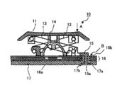
- FIG. 16 shows a conventional key switch structure provided with the link mechanism disclosed in the above document.
- a conventional key switch 10 includes a key top 11, a first link member 12 provided to be rotatable with respect to the key top 11, and a second provided to be slidable with respect to the key top 11.
- the link member 13 is bent when the key top 11 is pressed, and a rubber dome (elastic return member) 14 that returns the key top 11 to its original position when the pressing force is removed, and first and second links.
- a holder 15 that holds the members 12 and 13, a membrane sheet 16 having a contact portion 16 a immediately below the rubber dome 14, and a back plate 17 to which the holder 15 is fixed.
- the first link member 12 and the second link member 13 constitute a link mechanism.
- the back plate 17 is formed with a projecting portion 17a protruding upward, and this projecting portion 17a enters the through hole 16b formed in the membrane sheet 16. Further, a welding pin 15 a is formed at the lower part of the holder 15, and the welding pin 15 a enters a hole 17 b formed in the launching portion 17 a of the back plate 17. The back plate 17 is welded to the holder 15 with the membrane sheet 16 in between, with the welding pin 15a entering the hole 17b.
- the key top 11 is lowered while maintaining the horizontal state by the link mechanism including the first and second link members 12 and 13.
- the link mechanism including the first and second link members 12 and 13.
- the right end portion of the first link member 12 is lowered.
- the left end portion of the first link member 12 moves to the left side.
- the center part of the 1st link member 12 falls, and the 2nd link member 13 connected with the 1st link member 12 in the center part also falls.
- the second link member 13 is lowered, the left end portion of the key top 11 is also lowered.
- the key top 11 is lowered while maintaining a horizontal state, so that there is no difference in operational feeling depending on the pressed position, that is, operability is ensured. ing.
- the link mechanism composed of the first link member and the second link member is arranged so as to surround the rubber dome. That is, the portions where the first link member and the second link member overlap in the horizontal direction are located on both sides of the rubber dome. Therefore, there is a problem that a wider space is required for disposing the link mechanism on both sides of the rubber dome, and it is difficult to reduce the width of the key switch.
- the holder side of one link member can be slid and the key top side of the other link member can be slid. Since it is movable, there is also a problem that when the key top is pressed, the key top is lowered while being displaced in the horizontal direction.
- the present invention provides a support member for supporting the key top so that the key top can be moved up and down in a key switch structure in which the key top is pressed to conduct a contact and the key top is returned to the original position by a return member
- the plurality of support members are each characterized in that at least one side is equal to or smaller than the arrangement diameter of the return member. You may make it provide the holding
- a first restricting portion for restricting a positional deviation of at least one of the plurality of supporting members in a predetermined direction; and a second restricting part for a positional deviation of the key top in the predetermined direction with respect to the at least one supporting member. You may make it provide a control part.
- the support member can be configured not to be disposed around the return member, and a narrow key switch can be provided. Further, by providing a holding portion for holding the key top when not pressed in a horizontal state on at least one of the plurality of support members, the key top when not pressed can be held in a horizontal state.
- a first restricting portion for restricting a positional deviation of at least one of the plurality of supporting members in a predetermined direction; and a second restricting part for a positional deviation of the key top in the predetermined direction with respect to the at least one supporting member.
- FIG. 1 It is a top view which shows the key switch structure of Example 1 of this invention. It is a side view which shows the key switch structure of Example 1.
- FIG. It is a side view which shows the 1st support part of Example 1, and its periphery.
- FIG. 3 is an enlarged plan view showing a first support member of Example 1 and its periphery. It is a side view which shows a 2nd support part and its periphery. It is a side view which shows a 2nd sliding holding part. It is a side view which shows a 3rd supporting member and its periphery. It is a top view which shows a 1st holder. It is a top view which shows a 2nd holder.
- FIG. 6 is a plan view illustrating a key switch according to a second embodiment. It is sectional drawing which shows the conventional key switch structure provided with the link mechanism.
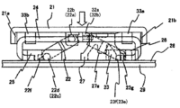
- FIG. 1 is a plan view showing a key switch structure according to a first embodiment of the present invention
- FIG. 2 is a side view showing the key switch structure according to the first embodiment.
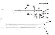
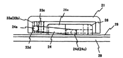
- the key switch 20 includes a key top 21, a first support member 22 that supports the key top 21 so as to be movable up and down, a second support member 23, and a third support member 24.
- the first holder 25 holding the first support member 22 and the third support member 24, the second holder 26 holding the second support member 23 and the third support member 24, and the key top 21 are bent when pressed.
- the key top 21 is indicated by a broken line for convenience of explanation.
- a pair of first sliding holding portions 31a and 31b, a pair of second sliding holding portions 32a and 32b, and a pair of rotation holding portions 33a and 33b are provided on the lower surface of the key top 21.
- the first sliding holding portions 31 a and 31 b are slidably engaged with sliding pins 22 a and 22 b formed on both side surfaces of one end portion of the first support member 22.
- the sliding pins 22a and 22b slide in the groove portions 31c and 31d when the key top 21 is pressed and when the key top 21 returns to the original position.
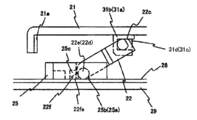
- FIG. 3 is a side view showing the first support portion and its periphery.
- FIG. 4 is an enlarged plan view showing the first support member and its periphery. 3 and 4, the upper portions of the first sliding holding portions 31a and 31b are respectively extended in the center direction in the arrow Y direction of the key top 21, and the key top 21 is attached to the lower surfaces of the extended portions 31e and 31f.
- the chamfered portion 22c shown in FIG. 3
- the chamfered portion 22c comes into surface contact with the lower surfaces of the extension portions 31e and 31f, the key top 21 is held in a stable state when not pressed.
- Rotating pins 22d and 22e are formed on both side surfaces of the other end of the first support member 22, and the rotating pins 22d and 22e are rotatably fitted in grooves 25a and 25b formed in the first holder 25, respectively. .
- the positions of the front ends of the rotary pins 22d and 22e are regulated by the back walls 25aa and 25ba of the grooves 25a and 25b, respectively, so that the first support member 22 is regulated in the direction of the arrow Y shown in FIG.
- a protrusion 22 f is provided on the distal end side of the other end of the first support member 22. As shown in FIG.
- the protrusion 22 f regulates the rotation angle of the first support member 22, and a tapered surface 22 fa that comes into surface contact with the membrane sheet 26 when the first support member 22 rotates to a predetermined angle. Is formed. As shown in FIG. 4, the protrusion 22 f enters the groove 25 c of the first holder 25 in a rotatable manner.
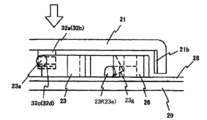
- the second sliding holding portions 32 a and 32 b are slidable at both end portions of the sliding cylindrical portion 23 a formed on both side surfaces of one end portion of the second support member 23.
- Engaging groove portions 32c and 32d are provided, and the sliding cylindrical portion 23a slides in the groove portions 32c and 32d when the key top 21 is pressed down and when the key top 21 returns to the original position.
- the position of the key top 21 is regulated in the direction of the arrow Y shown in FIG. 6 by engaging both end portions of the sliding cylindrical portion 23a with the groove portions 32c and 32d, respectively.
- 5 is a side view showing the second support member and its periphery
- FIG. 6 is a side view showing the second sliding holding portion.
- rotation pins 23e and 23f are formed on both side surfaces of the other end of the second support member 23.
- the rotation pins 23e and 23f are respectively formed in grooves 26a and 26b formed in the second holder 26. It is inserted so that it can rotate.
- the positions of the distal ends of the rotary pins 23e and 23f are restricted by the inner walls of the grooves 26a and 26b, respectively, whereby the position of the second support member 23 is restricted in the direction of the arrow Y shown in FIG.
- a chamfer 23 g is formed at the other end of the second support member 23.
- the chamfered portion 23g regulates the rotation angle of the second support member 23 as shown in FIG. 5, and makes surface contact with the membrane sheet 26 when the second support member 23 rotates to a predetermined angle.
- the other end of the second support member 23 enters the groove 26 c of the second holder 26 so as to be rotatable.
- the second support member 23 is formed of a crank-shaped prism, and the side surfaces 23 h and 23 i are also in sliding contact with the inner wall portions 26 g and 26 h of the second holder 26.
- the position of the member 23 is restricted in the arrow Y direction shown in FIG.
- the shape of the support member can be changed according to the shape and size of the key switch or the arrangement of the rubber dome. Correspondence is possible.
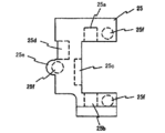
- the pair of rotation holding portions 33a and 33b hold the third support member 24 rotatably. That is, as shown in FIGS. 1 and 7, the rotation holding portions 33a and 33b respectively have groove portions 33c and 33d that rotatably hold the support shaft portion 24a of the third support member 24.
- the support shaft portion 24a When the key top 21 is pressed and when the key top 21 is returned to the original position from the pressed state, the groove portions 33c and 33d are rotated.
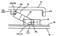
- FIG. 7 is a side view showing the third support member and its periphery.
- the third support member 24 is generally formed in a U-shape and has side end portions 24b and 24c and tip end portions 24d and 24e in addition to the support shaft portion 24a. As shown in FIG. 1, one end portion 24 d is fitted in a groove portion 25 d formed in the first holder 25 so as to be slidable in the arrow Y direction. A protrusion 25 e is formed on the first holder 25, and the tip of the protrusion 25 e is in contact with the inner side of the side end 24 b of the third support member 24. Further, a fixed wall 21 a is formed to protrude inside the end portion of the key top 21, and the fixed wall 21 a is in contact with the outside of the side end portion 24 b of the third support member 24.
- the side end 24b of the third support member 24 is slidably held by the protrusion 25e and the fixed wall 21a.
- the side end 24b of the third support member 24 rotates as the key top 21 is pressed.
- the protrusion 25e and the fixed wall 21a are always side ends even if the side end 24b rotates. It is formed in a shape and a position so as to contact the portion 24b.
- the other tip 24e of the third support member 24 is slidably fitted in a groove 26d formed in the second holder 26 in the arrow Y direction, as shown in FIG.
- a wall portion 26 e is formed on the second holder 26, and the wall portion 26 e is in contact with the inner side of the side end portion 24 c of the third support member 24.
- a fixed wall 21 b is formed to protrude inside the end portion of the key top 21, and the fixed wall 21 b is in contact with the outside of the side end portion 24 c of the third support member 24. That is, the side end 24c of the third support member 24 is slidably held by the wall 26e and the fixed wall 21b.
- the wall portion 26e and the fixed wall 21b are formed in a shape and a position so that the side end portion 24c of the third support member 24 always abuts on the side end portion 24c even when the side end portion 24c rotates.
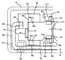
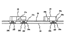
- FIG. 8 is a plan view showing the first holder.
- the first holder 25 is provided with a plurality (three) of fixing pins 25f
- the second holder 26 is also provided with a plurality (two) of fixing pins 26f as shown in FIG. Is provided.
- These fixing pins 25f and 26f are inserted and welded into holes 29b formed in the projecting portions 29a formed in the back plate 29 shown in FIG.
- the upper portion of the launching portion 29 a is inserted into a hole 28 a formed in the membrane sheet 28, and the first holder 25 and the second holder 26 are directly fixed to the back plate 29.
- the rubber dome (return member) 27 is disposed between the membrane sheet 28 and the key top 21, and a protrusion 27 a that presses the membrane sheet 28 when the key top 21 is pressed is formed.
- the membrane sheet 28 below the protrusion 27a is provided with a contact portion. When the protrusion 27a presses the contact portion, the contact portion is electrically connected.
- FIG. 11 is an explanatory diagram showing the relationship in size between the first support member 22, the second support member 23, the third support member 24, and the rubber dome 27 of the present embodiment.
- the diameter (arrangement diameter) of the rubber dome 27 is L
- L2 is the width of the second support member 23 (similarly, the shorter side length when the second support member 23 is rectangular)
- the third support member is L3.
- L1, L2, and L3 are all set to a diameter L or less of the rubber dome 27 (L1 ⁇ L, L2 ⁇ L, L3 ⁇ L).
- the support member can be arranged without being trapped by the diameter of the rubber dome 27.
- the support member by making the support member smaller than the diameter of the rubber dome 27, it is possible to reduce the size of the support member itself, thereby reducing the size of the key switch itself. Furthermore, it is possible to flexibly cope with the shape of the key switch.
- the state before the key top 21 is pressed is the state shown in FIG. In this state, since the taper surface 22fa of the protrusion 22f of the first support member 22 is in surface contact with the membrane sheet 28, the chamfered portion 22c formed at the end of the first support member 22 is the first. Since the surface is in contact with the extension portions 31e and 31f of the sliding holding portions 31a and 31b, the key top 21 is held in a stable state. Further, since the chamfered portion 23g formed on the second support member 23 is in surface contact with the membrane sheet 28, the key top 21 is held in a stable state also by this.
- the second support member 23 rotates counterclockwise in FIG. 2 around the rotation pins 23e and 23f. At this time, the sliding cylindrical portion 23a slides in the horizontal direction in the grooves 32c and 32d of the second sliding holding portions 32a and 32b.
- the second support member 23 is in a substantially horizontal state as shown in FIG.
- the third support member 24 rotates counterclockwise from the state shown in FIG. 7 around the support shaft portion 24a held by the rotation holding portions 33a and 33b. At this time, the tip portions 24d and 24e of the third support member 24 slide in the horizontal direction in the groove portion 25d of the first holder 25 and the groove portion 26d of the second holder 26, respectively. When the key top 21 is pushed down to the lowest position, the third support member 24 becomes substantially horizontal as shown in FIG.
- the first support member 22 has the distal end portions of the rotation pins 22d and 22e at the back walls 25aa of the groove portions 25a and 25b of the first holder 25, respectively. , 25ba, the positional deviation in the arrow Y direction is regulated.
- the positions of the outer walls 31ca and 31da of the groove portions 31c and 31d are regulated by the tip portions of the sliding pins 22a and 22b of the first support member 22, respectively. 21 is restricted from shifting in the arrow Y direction.
- the side surfaces 23h and 23i of the second support member 23 are slidably in contact with the inner wall portions 26g and 26h of the second holder 26, thereby restricting the displacement in the arrow Y direction. Is done.
- the positions of the inner portions of the groove portions 32c and 32d are regulated by the tip portion of the sliding cylindrical portion 23a of the second support member 23, respectively. The positional deviation in the Y direction is restricted.
- the third support member 24 has an inner side of one side end portion 24 b in contact with the protruding portion 25 e of the first holder 25, and an inner side of the other side end portion 24 c is a wall of the second holder 26.
- the position shift in the arrow X direction is regulated by contacting the portion 26e.
- a fixed wall 21a formed inwardly on the key top 21 abuts on the outer side of the side end 24b of the third support member 24, and is similarly formed on the opposite side of the key top 21 inward.
- 21 b is in contact with the outside of the other side end 24 c of the third support member 24.
- the key top 21 is restricted from being displaced in the direction of the arrow X.
- the key top 21 does not shift in the direction of the arrow X or the direction of the arrow Y, and does not tilt or rotate. To do.
- the key top 21 is kept horizontal and descends in the vertical direction. As a result, the rubber dome 27 is pressed by the back surface of the key top 21 and buckles. The projecting portion 27a of the buckled rubber dome 27 presses a contact portion (not shown) of the membrane sheet 28, and the key switch is electrically conducted.
- the key top 21 is pushed up by the restoring force of the rubber dome 27 and moves upward.
- Each of the support members 24 performs an operation in the opposite direction to that when the key member 21 is pressed, and the key top 21 moves upward while maintaining a horizontal state.
- each of the first support member 22, the second support member 23, and the third support member 24 is set to be equal to or smaller than the arrangement diameter of the rubber dome 27, the support member is the rubber dome.
- the width of the key switch can be reduced.
- the size of the rubber dome 27 can be increased relative to the size of the key top 21, it is possible to increase the stroke and life of the key switch.
- the protrusion 22f and the chamfer 22c for restricting the rotation angle are formed on the first support member 22, and the chamfer 23g is also formed on the second support member 23. 21 can maintain a horizontal state reliably. Further, since it has a function of preventing the position of the key top 21 from being displaced, when it is pressed, the key top 21 moves down in the vertical direction without being displaced in both the X and Y directions.
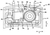
- FIG. 15 is a plan view showing the key switch of the second embodiment.
- the key switch 40 according to the second embodiment includes a key top 41, a first support member 42 that supports the key top 41 so as to move up and down, a second support member 43 and a third support member 24,
- the second holder 45 that holds the support member 42 and the third support member 24, the second holder 46 that holds the second support member 43 and the third support member 24, and the key top 41 bends and depresses. Is removed, the rubber dome 27 returns the key top 41 to its original position, and a membrane sheet and a back plate having a contact portion (not shown) immediately below the rubber dome 27. (The membrane sheet and back plate are not shown.)
- the planar shape of the key top 41 is not a rectangle but a curved shape.
- the first support member 42 has the same shape as the first support member 22 of the first embodiment and can be rotated in the same manner.
- the rotation shaft 42a has the shape of the key top 41 by an angle ⁇ 1 with respect to the arrow Y direction. It is displaced in the direction along. Accordingly, the grooves 45a, 45b, 45c of the first holder 45 are formed to be inclined with respect to those of the first embodiment by the angle ⁇ 1 with respect to the arrow Y direction, and the first sliding holding portions 51a, 51b are formed. Is also inclined with respect to the arrow Y direction by an angle ⁇ 1.
- the second support member 43 has the same shape as the second support member 23 of the first embodiment and can be rotated in the same manner.
- the rotation shaft 43a has a shape of the key top 41 by an angle ⁇ 2 with respect to the arrow Y direction. It is displaced in the direction along.
- the grooves 46a and 46b of the second holder 26 are formed so as to be inclined with respect to those of the first embodiment by the angle ⁇ 2 with respect to the arrow Y direction, and the second sliding holding portions 52a and 52b are also formed in the arrow Y direction. In contrast, it is arranged to be inclined by an angle ⁇ 2.
- Other configurations are the same as those of the first embodiment.
- the operation by pressing the key top 41 is the same as that in the first embodiment.
- the first support member 42 and the second support member 43 are disposed at an inclination, whereby the arrangement along the shape of the key top 41 can be achieved.
- the key top 41 can be kept in a horizontal state without being tilted no matter where the upper surface of the key top 41 is pressed. It is possible to descend while keeping.
- the present invention is not limited to three support members, and may be two, four, or other numbers.
- the example which uses three types of shape support members, plate shape (1st support member), prismatic shape (2nd support member), and round bar shape (3rd support member) as a shape of a support member is shown.
- shape support members plate shape (1st support member), prismatic shape (2nd support member), and round bar shape (3rd support member) as a shape of a support member.
- the first support member and the second support member have a crank shape, but by using the crank shape, it is possible to give flexibility to the arrangement of the support member, and further according to the shape of the key switch. Can be arranged. That is, the crank shape of the support member can be flexibly changed according to the shape and arrangement position of the key switch.
- the key switch structure of the present invention is used for a keyboard device used as an input device in an information processing device, a measuring device, a medical device, etc., and particularly used for a keyboard device as an input device for a small and thin personal computer.
Landscapes
- Push-Button Switches (AREA)
- Input From Keyboards Or The Like (AREA)
Priority Applications (2)
| Application Number | Priority Date | Filing Date | Title |
|---|---|---|---|
| US13/701,354 US9082564B2 (en) | 2010-06-28 | 2011-05-09 | Key support arrangement for narrow key switch structure |
| CN201180025505.8A CN102906843B (zh) | 2010-06-28 | 2011-05-09 | 键开关结构 |
Applications Claiming Priority (2)
| Application Number | Priority Date | Filing Date | Title |
|---|---|---|---|
| JP2010-146407 | 2010-06-28 | ||
| JP2010146407A JP5621353B2 (ja) | 2010-06-28 | 2010-06-28 | キースイッチ構造 |
Publications (1)
| Publication Number | Publication Date |
|---|---|
| WO2012002035A1 true WO2012002035A1 (ja) | 2012-01-05 |
Family
ID=45401771
Family Applications (1)
| Application Number | Title | Priority Date | Filing Date |
|---|---|---|---|
| PCT/JP2011/060652 Ceased WO2012002035A1 (ja) | 2010-06-28 | 2011-05-09 | キースイッチ構造 |
Country Status (5)
| Country | Link |
|---|---|
| US (1) | US9082564B2 (enExample) |
| JP (1) | JP5621353B2 (enExample) |
| CN (1) | CN102906843B (enExample) |
| TW (1) | TWI430309B (enExample) |
| WO (1) | WO2012002035A1 (enExample) |
Families Citing this family (9)
| Publication number | Priority date | Publication date | Assignee | Title |
|---|---|---|---|---|
| CN109755062A (zh) * | 2017-11-08 | 2019-05-14 | 致伸科技股份有限公司 | 键盘 |
| US10867759B2 (en) | 2019-04-11 | 2020-12-15 | Darfon Electronics Corp. | Keyswitch structure |
| TWI703603B (zh) * | 2019-04-11 | 2020-09-01 | 達方電子股份有限公司 | 按鍵結構 |
| US11264186B2 (en) | 2019-04-11 | 2022-03-01 | Darfon Electronics Corp. | Keyswitch structure |
| US11538644B2 (en) | 2019-04-11 | 2022-12-27 | Darfon Electronics Corp. | Keyswitch structure |
| US10984968B2 (en) | 2019-05-22 | 2021-04-20 | Darfon Electronics Corp. | Keyswitch structure |
| TWI713064B (zh) * | 2019-05-22 | 2020-12-11 | 達方電子股份有限公司 | 按鍵結構 |
| CN110265252A (zh) * | 2019-05-31 | 2019-09-20 | 苏州达方电子有限公司 | 按键结构 |
| TWI691989B (zh) * | 2019-10-15 | 2020-04-21 | 群光電子股份有限公司 | 鍵盤裝置 |
Citations (4)
| Publication number | Priority date | Publication date | Assignee | Title |
|---|---|---|---|---|
| JPH07296673A (ja) * | 1994-04-22 | 1995-11-10 | Mitsumi Electric Co Ltd | キーボードスイッチ |
| JPH1139986A (ja) * | 1997-07-15 | 1999-02-12 | Mitsumi Electric Co Ltd | キーボードスイッチ |
| JPH11265632A (ja) * | 1999-02-03 | 1999-09-28 | Brother Ind Ltd | キ―スイッチ |
| JP2002208327A (ja) * | 2001-01-11 | 2002-07-26 | Smk Corp | キースイッチ |
Family Cites Families (14)
| Publication number | Priority date | Publication date | Assignee | Title |
|---|---|---|---|---|
| US4433225A (en) * | 1983-02-22 | 1984-02-21 | General Instrument Corporation | Keytop levelling mechanism |
| JP2590622Y2 (ja) * | 1992-03-30 | 1999-02-17 | ブラザー工業株式会社 | キースイッチ装置 |
| JPH1116440A (ja) * | 1997-06-23 | 1999-01-22 | Mitsumi Electric Co Ltd | キーボードスイッチ |
| JP4349674B2 (ja) | 1999-03-04 | 2009-10-21 | 富士通コンポーネント株式会社 | キースイッチ装置及びキーボード |
| JP2001202849A (ja) | 2000-01-21 | 2001-07-27 | Brother Ind Ltd | キースイッチ装置、キースイッチ装置を備えたキーボード及びキーボードを備えた電子機器 |
| JP4341733B2 (ja) | 2000-02-15 | 2009-10-07 | 株式会社 沖情報システムズ | キースイッチ構造 |
| JP2003197058A (ja) * | 2001-12-27 | 2003-07-11 | Alps Electric Co Ltd | キースイッチ装置及びキーボード装置 |
| JP2004079322A (ja) * | 2002-08-16 | 2004-03-11 | Fujitsu Ltd | キーボード及びそれを有する電子機器 |
| JP2007227024A (ja) * | 2006-02-21 | 2007-09-06 | Mitsumi Electric Co Ltd | キースイッチ装置 |
| TWI314750B (en) * | 2006-05-23 | 2009-09-11 | Darfon Electronics Corp | Keyboard with wobble prevention structure |
| TW201005780A (en) | 2008-07-30 | 2010-02-01 | Chicony Electronic Co Ltd | Key structure |
| US8080744B2 (en) * | 2008-09-17 | 2011-12-20 | Darfon Electronics Corp. | Keyboard and keyswitch |
| US20110102323A1 (en) * | 2009-11-04 | 2011-05-05 | Tonny Chen | Keyboard having multi-axis balance touch keys |
| US9024214B2 (en) * | 2010-06-11 | 2015-05-05 | Apple Inc. | Narrow key switch |
-
2010
- 2010-06-28 JP JP2010146407A patent/JP5621353B2/ja active Active
-
2011
- 2011-04-20 TW TW100113708A patent/TWI430309B/zh active
- 2011-05-09 US US13/701,354 patent/US9082564B2/en active Active
- 2011-05-09 WO PCT/JP2011/060652 patent/WO2012002035A1/ja not_active Ceased
- 2011-05-09 CN CN201180025505.8A patent/CN102906843B/zh not_active Expired - Fee Related
Patent Citations (4)
| Publication number | Priority date | Publication date | Assignee | Title |
|---|---|---|---|---|
| JPH07296673A (ja) * | 1994-04-22 | 1995-11-10 | Mitsumi Electric Co Ltd | キーボードスイッチ |
| JPH1139986A (ja) * | 1997-07-15 | 1999-02-12 | Mitsumi Electric Co Ltd | キーボードスイッチ |
| JPH11265632A (ja) * | 1999-02-03 | 1999-09-28 | Brother Ind Ltd | キ―スイッチ |
| JP2002208327A (ja) * | 2001-01-11 | 2002-07-26 | Smk Corp | キースイッチ |
Also Published As
| Publication number | Publication date |
|---|---|
| TW201203302A (en) | 2012-01-16 |
| CN102906843A (zh) | 2013-01-30 |
| TWI430309B (zh) | 2014-03-11 |
| US9082564B2 (en) | 2015-07-14 |
| JP2012009386A (ja) | 2012-01-12 |
| JP5621353B2 (ja) | 2014-11-12 |
| US20130078023A1 (en) | 2013-03-28 |
| CN102906843B (zh) | 2015-05-27 |
Similar Documents
| Publication | Publication Date | Title |
|---|---|---|
| JP5621353B2 (ja) | キースイッチ構造 | |
| JP4468431B2 (ja) | 多方向操作スイッチ装置 | |
| US10061396B1 (en) | Electronic apparatus | |
| JP6209575B2 (ja) | 多方向入力装置 | |
| TWI402877B (zh) | A key switch device and a keypad having a key switch device | |
| KR101099030B1 (ko) | 휴대용 단말기의 다방향 슬라이드 입력장치 | |
| JP5248392B2 (ja) | 多方向操作部品 | |
| JP6808006B1 (ja) | キーボード装置 | |
| JP5015900B2 (ja) | キーボード装置 | |
| JP5072903B2 (ja) | キースイッチ装置及びキーボード | |
| JP4522376B2 (ja) | 多方向入力装置 | |
| JP4908103B2 (ja) | 多方向操作スイッチ構造 | |
| JP4653001B2 (ja) | スイッチ装置 | |
| JP2010199961A (ja) | スライド式小型電子機器 | |
| JP3387917B2 (ja) | キースイッチ装置 | |
| JP3451082B2 (ja) | キースイッチ装置 | |
| JP3451081B2 (ja) | キースイッチ装置 | |
| JP2004039653A (ja) | キースイッチ装置 | |
| KR101106766B1 (ko) | 휴대용 단말기의 다방향 슬라이드 입력장치 | |
| JP2015056340A (ja) | キースイッチ | |
| JP2003086048A (ja) | キースイッチ装置、キースイッチ装置を備えたキーボード及びキーボードを備えた電子機器 | |
| JP2009087914A (ja) | 押しボタンスイッチ装置 | |
| JP2001126582A (ja) | キースイッチ装置 | |
| JP2003123579A (ja) | キースイッチ装置 | |
| JP2001052559A (ja) | キースイッチ装置 |
Legal Events
| Date | Code | Title | Description |
|---|---|---|---|
| WWE | Wipo information: entry into national phase |
Ref document number: 201180025505.8 Country of ref document: CN |
|
| 121 | Ep: the epo has been informed by wipo that ep was designated in this application |
Ref document number: 11800505 Country of ref document: EP Kind code of ref document: A1 |
|
| WWE | Wipo information: entry into national phase |
Ref document number: 13701354 Country of ref document: US |
|
| NENP | Non-entry into the national phase |
Ref country code: DE |
|
| 122 | Ep: pct application non-entry in european phase |
Ref document number: 11800505 Country of ref document: EP Kind code of ref document: A1 |