WO2011161995A1 - パネル取付構造 - Google Patents
パネル取付構造 Download PDFInfo
- Publication number
- WO2011161995A1 WO2011161995A1 PCT/JP2011/056721 JP2011056721W WO2011161995A1 WO 2011161995 A1 WO2011161995 A1 WO 2011161995A1 JP 2011056721 W JP2011056721 W JP 2011056721W WO 2011161995 A1 WO2011161995 A1 WO 2011161995A1
- Authority
- WO
- WIPO (PCT)
- Prior art keywords
- locking
- locked
- panel
- slider
- release lever
- Prior art date
- Legal status (The legal status is an assumption and is not a legal conclusion. Google has not performed a legal analysis and makes no representation as to the accuracy of the status listed.)
- Ceased
Links
Images






Classifications
-
- E—FIXED CONSTRUCTIONS
- E04—BUILDING
- E04F—FINISHING WORK ON BUILDINGS, e.g. STAIRS, FLOORS
- E04F13/00—Coverings or linings, e.g. for walls or ceilings
- E04F13/07—Coverings or linings, e.g. for walls or ceilings composed of covering or lining elements; Sub-structures therefor; Fastening means therefor
- E04F13/08—Coverings or linings, e.g. for walls or ceilings composed of covering or lining elements; Sub-structures therefor; Fastening means therefor composed of a plurality of similar covering or lining elements
- E04F13/0801—Separate fastening elements
- E04F13/0803—Separate fastening elements with load-supporting elongated furring elements between wall and covering elements
- E04F13/081—Separate fastening elements with load-supporting elongated furring elements between wall and covering elements with additional fastening elements between furring elements and covering elements
- E04F13/0812—Separate fastening elements with load-supporting elongated furring elements between wall and covering elements with additional fastening elements between furring elements and covering elements fixed by means of spring action
-
- E—FIXED CONSTRUCTIONS
- E04—BUILDING
- E04F—FINISHING WORK ON BUILDINGS, e.g. STAIRS, FLOORS
- E04F13/00—Coverings or linings, e.g. for walls or ceilings
- E04F13/07—Coverings or linings, e.g. for walls or ceilings composed of covering or lining elements; Sub-structures therefor; Fastening means therefor
- E04F13/08—Coverings or linings, e.g. for walls or ceilings composed of covering or lining elements; Sub-structures therefor; Fastening means therefor composed of a plurality of similar covering or lining elements
- E04F13/0801—Separate fastening elements
- E04F13/0803—Separate fastening elements with load-supporting elongated furring elements between wall and covering elements
- E04F13/081—Separate fastening elements with load-supporting elongated furring elements between wall and covering elements with additional fastening elements between furring elements and covering elements
- E04F13/083—Hooking means on the back side of the covering elements
-
- E—FIXED CONSTRUCTIONS
- E05—LOCKS; KEYS; WINDOW OR DOOR FITTINGS; SAFES
- E05B—LOCKS; ACCESSORIES THEREFOR; HANDCUFFS
- E05B65/00—Locks or fastenings for special use
- E05B65/006—Locks or fastenings for special use for covers or panels
-
- E—FIXED CONSTRUCTIONS
- E05—LOCKS; KEYS; WINDOW OR DOOR FITTINGS; SAFES
- E05C—BOLTS OR FASTENING DEVICES FOR WINGS, SPECIALLY FOR DOORS OR WINDOWS
- E05C1/00—Fastening devices with bolts moving rectilinearly
- E05C1/08—Fastening devices with bolts moving rectilinearly with latching action
-
- E—FIXED CONSTRUCTIONS
- E05—LOCKS; KEYS; WINDOW OR DOOR FITTINGS; SAFES
- E05B—LOCKS; ACCESSORIES THEREFOR; HANDCUFFS
- E05B15/00—Other details of locks; Parts for engagement by bolts of fastening devices
- E05B15/0093—Weight arrangements in locks; gravity activated lock parts
-
- E—FIXED CONSTRUCTIONS
- E05—LOCKS; KEYS; WINDOW OR DOOR FITTINGS; SAFES
- E05B—LOCKS; ACCESSORIES THEREFOR; HANDCUFFS
- E05B63/00—Locks or fastenings with special structural characteristics
- E05B63/18—Locks or fastenings with special structural characteristics with arrangements independent of the locking mechanism for retaining the bolt or latch in the retracted position
- E05B63/20—Locks or fastenings with special structural characteristics with arrangements independent of the locking mechanism for retaining the bolt or latch in the retracted position released automatically when the wing is closed
-
- E—FIXED CONSTRUCTIONS
- E05—LOCKS; KEYS; WINDOW OR DOOR FITTINGS; SAFES
- E05C—BOLTS OR FASTENING DEVICES FOR WINGS, SPECIALLY FOR DOORS OR WINDOWS
- E05C19/00—Other devices specially designed for securing wings, e.g. with suction cups
- E05C19/06—Other devices specially designed for securing wings, e.g. with suction cups in which the securing part if formed or carried by a spring and moves only by distortion of the spring, e.g. snaps
Definitions
- the present invention relates to a panel mounting structure for detachably mounting a panel on a wall surface.
- Patent Documents 1 and 2 can be cited.
- Patent Document 1 a support hole is formed in a support member provided on the back surface of the panel, and an upper edge of the support hole is hooked on a pin provided on a wall surface (support wall portion). That connects the wall and the wall.
- Patent Document 2 listed below locks a pair of left and right barrel edge locking brackets that are respectively attached to adjacent portions of adjacent studs to lock both ends of the trunk edge provided on the back surface of the panel. Has been.
- Patent Document 1 the structure described in Patent Document 1 is not easy to mount because it is fixed with a connector after hooking a pin in the support hole, and it cannot be easily removed after mounting. It has become.
- the thing of the said patent document 2 needs to lift a panel upwards and to lock
- the present invention has been made in view of the above circumstances, and an object thereof is to provide a panel mounting structure in which a panel can be easily attached and detached.
- a panel mounting structure is a panel mounting structure in which a plurality of panels are detachably mounted on a wall surface with a gap between them, either the wall surface or the back surface of the panel.
- a locking portion is provided on one side, and a locked portion to be locked to the locking portion is provided on the other side, and the locked portion is locked to the locking portion by receiving a pressure from the panel.
- the locking state between the locking portion and the locked portion is released by operating a release lever provided on the locking portion side or the locked portion side from the gap.
- the locking portion is formed on a front side of a locking slider that moves up and down, and the locking slider moves by the pressing, and the hook-shaped locked portion is engaged with the locking portion. It may be stopped.
- the locking slider includes a lock plate that restricts the vertical movement of the locking slider. When the locking plate receives the pressure, the locking slider releases the locked state with respect to the locking slider.
- the latching portion is allowed to move to a latching position where the latched portion is latched by the biasing force of the biasing member, the latched portion is latched by the latching portion, and the release lever Is operated to release the locking state against the biasing force of the biasing member, and the locking slider may be locked by the lock plate.
- the locking part and the locked part are formed in a shape that meshes with each other, and when the pressing is received, the locked part comes into contact with the locking part and the locking slider is raised.
- the locked portion is pushed to the locking position with the locking portion, the locking slider is lowered by its own weight, the locked portion is locked to the locking portion, and The locking state may be released by operating a release lever upward against the weight of the locking slider.
- the said to-be-latched part consists of the protrusion piece which protruded toward the said engaging part, and the said protrusion piece is engage
- the said protrusion The piece may be locked in the recess, and the locked state may be released by rotating the release lever.
- a plurality of the locking portions and the locked portions are provided, and an interlocking member that interlocks with the locking portions by a plurality of the locking portions being interlocked by pressing from the panel. It may be provided.
- locking part and the said to-be-latched part operates the release lever provided in the said latching
- the plurality of locking portions are respectively formed on the front side of a locking slider that moves up and down, and the plurality of locking sliders are arranged side by side in the vertical direction.
- the locking slider provided above is locked in a state where a force in a direction to lock the locked portion is accumulated by a lock plate, and the lock plate receives the pressure from the panel and By releasing the locked state with respect to the uppermost locking slider, the other locking slider may be moved by the interlocking member, and the locked portion may be locked to the locking portion.
- the plurality of locking sliders are biased by a biasing member in a direction in which the locking portions are locked to the locked portions, and other than the locking slider provided at the uppermost position.
- the locking slider and the interlocking member are interlocked with the movement of the locking slider provided at the uppermost position through a shaft portion that is movably inserted into a long hole provided in the interlocking member. May be.
- a fixed column may be provided at a position corresponding to the gap of the wall surface, and the locking portion or the locked portion may be attached to the fixed column.
- the panel mounting structure according to the present invention has the above-described configuration, so that the panel can be easily attached and detached.
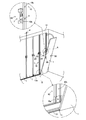
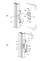
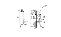
- (A) And (b) is a typical side view for demonstrating the panel mounting structure which concerns on one Embodiment of this invention. It is a typical perspective view for demonstrating the panel mounting structure. It is a disassembled perspective view for demonstrating fixing mechanism parts, such as a latching slider in which the latching part employ
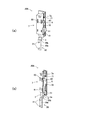
- (A) And (b) is a typical perspective view for demonstrating the latching operation
- (A) And (b) is a typical perspective view for demonstrating the modification of the panel mounting structure.
- (A)-(c) is a typical side view for demonstrating the panel attachment structure which concerns on other embodiment of this invention.
- A) And (b) is a typical perspective view for demonstrating the latching operation
- A) And (b) is a typical perspective view for demonstrating the latch release operation
- FIG. 1 to (c) are schematic perspective views for explaining the locking operation and the locking releasing operation of the locking portion and the locked portion employed in the panel mounting structure according to another embodiment of the present invention. It is a figure and typical sectional drawing.
- (A) And (b) is a typical perspective view for demonstrating operation
- (A) And (b) is a typical perspective view for demonstrating the fixing mechanism part and cancellation
- (A) And (b) is a typical side view for demonstrating the latching operation of the latching
- (A) And (b) is a typical perspective view for demonstrating the latching operation
- FIG. 1 to 7 are explanatory views for explaining a panel mounting structure according to the first embodiment.
- the side of the fixed column 10 is omitted for easy understanding of the operation state of the lock plate 6, and the panel 1 and the fixed column 10 are not illustrated for the sake of explanation in FIG. 4.
- . 6 and 7 also schematically show only the main part for the sake of explanation.
- the panel mounting structure according to the present embodiment is a panel mounting structure in which a plurality of panels 1 are detachably mounted on a wall surface 12 with a gap d therebetween.
- the locking portion 2 and the back surface of the panel 1 are mounted on the wall surface 12.
- a locked portion 3 is provided in 1a, and the locked portion 3 is locked to the locking portion 2 by receiving a pressure from the panel 1, and a release lever 4 provided on the locking portion 2 side. Is operated from the gap, the locked state between the locking portion 2 and the locked portion 3 is released.
- the panel 1 is installed substantially vertically along the wall surface 12 and is formed in a vertically long thin rectangular shape.
- the panel 1 is not particularly limited, the panel 1 is configured so that it can be easily attached and detached without lifting the panel 1 upward.
- a functional panel having a humidity control function, a deodorizing function, etc. A panel having a height close to that is suitable. Therefore, although not shown here, a panel having an exhaust port, an intake port, or the like may be used, or a panel body having high design properties may be used.
- the lower end portion of the panel 1 may be formed with a notched groove portion 1b formed by partially cutting the end face as shown in the figure (see FIG. 2 and the enlarged view of the B portion).
- the cut-out groove portion 1b has a lower surface cut into a concave shape when viewed in cross-section, and is cut from the end of the panel 1 along the horizontal direction when the panel 1 is attached.
- a locked tool 30 is fixed to the back surface 1 a of the panel 1 by a fixing tool 31 such as a screw.
- the locked tool 30 fixed to the back surface 1a of the panel 1 includes a fixing part 30a having an insertion hole through which the fixing tool 31 is inserted, and a hook-shaped hooking part 30b that becomes the locked part 3. It is formed in a substantially Z shape when viewed.
- a wall surface 12 to which the panel 1 is attached is formed with a recess 12 a having a front opening, and a plurality of fixed columns 10 are provided in the recess with a predetermined interval.
- the fixed column 10 is provided so that a slight gap d is formed between the panels 1 when the plurality of panels 1 are mounted side by side.
- the fixed column 10 is made of a metal material, a resin material, or the like, and has a shape (substantially U-shaped) having a concave strip portion 10c whose front surface is opened in a cross-sectional view.
- an insertion opening 10b (see the enlarged view of FIG. 2A) through which the release lever 4 is inserted is formed.
- the dimension in the longitudinal direction of the fixed column 10 is formed in accordance with the height dimension of the recess 12a.
- the thickness dimension of the fixed column 10 is set in the recess 12a and the front surface of the panel 1 is substantially flush with the wall surface 12 when the panel 1 is attached.
- the fixed column 10 has its upper and lower ends fixed by fixing members 10a.
- the fixing member 10a is directly connected and fixed to the recess 12a by a connecting tool such as a screw (see the enlarged view of FIG. 2B). ).
- the lower end portion of the recess 12a is in a fitting relationship with the notch groove portion 1b formed in the lower end portion of the panel 1 along the horizontal direction, and supports the lower end portion of the panel 1 and also serves as a positioning function for the mounting position. Is formed.
- the interval between the adjacent fixed columns 10 and the fixed columns 10 is set according to the dimension in the width direction of the panel 1, and the fixing mechanism unit 20 including the locking portion 2 is attached to a predetermined position of the fixed column 10.
- the above-described insertion opening 10b (see the enlarged view of FIG. 2A) is formed at a position where the fixing mechanism 20 is attached.
- FIGS. The example provided in the height position of the center position is shown.
- the rail portion 13 is formed at the lower end portion of the recess 12a
- the present invention is not limited thereto, and a peripheral edge may be provided at the upper end portion of the recess 12a. If the rail portion 13 is provided in this way, the panel 1 can be easily attached and installed substantially vertically to the floor surface.
- the example which has a clearance gap between the ceiling and the upper end part of the recess 12a is shown here, it is good also as what the upper end part of the recess 12a and the ceiling substantially correspond.
- the fixing mechanism portion 20 includes a locking slider 5 that moves up and down, a lock plate 6 that restricts the vertical movement of the locking slider 5, and a fixing mechanism portion main body 7 in which the locking slider 5 is housed.
- the locking slider 5 is a substantially rectangular block body as viewed from the side and is configured to move up and down triggered by the operation of the urging member 8 and the lock plate 6.
- On the side a gradually tapered inclined portion 2 a that becomes the locking portion 2 is formed.
- the inclined portion 2a is provided with an inclined surface inclined obliquely from the wall surface 12 side to the panel 1 side when the panel 1 is attached.
- the inclined portion 2a When the locked portion 3 comes into contact with the inclined surface, the inclined portion 2a is engaged with the wall surface 12 side. A component force that pulls the stop portion can be applied. Further, an urging member 8 is fixed to the other side of the locking slider 5, and here, an example in which a compression coil spring is used as the urging member 8 is shown. In the urging member 8, the locking slider 5 moves in the locking position direction between the locking portion 2 formed on the front side of the locking slider 5 and the locked portion 3 formed on the locked tool 30. It is configured as follows. Therefore, here, an example in which the locking slider 5 is lowered and the locking portion 2 and the locked portion 3 are locked, that is, an example in which the locking position is below, is shown. The urging force is provided to work downward with respect to the locking slider 5.
- a release lever 4 is formed integrally with the locking slider 5 on a side surface of the locking slider 5 and at a position close to the locking portion 2.
- the release lever 4 is formed as a thin plate piece.
- the release lever 4 is inserted into the insertion opening 10 b so as to protrude and be exposed in the concave portion 10 c of the fixed column 10. Is provided. That is, when the fixing mechanism main body 7 is attached to the fixing column 10, the tip of the release lever 4 is provided so as to protrude in parallel with the panel 1 and the back surface 1a as shown in the enlarged view of part A of FIG.
- the release lever 4 protrudes from the gap d in the fixed column 10, so that an operation of pulling up the release lever 4 by inserting a tool or the like into the gap d is performed. be able to.
- the procedure for attaching and detaching the panel 1 will be described in detail later.
- the release lever 4 is not necessarily formed integrally with the locking slider 5 as long as the release lever 4 is configured to be interlocked with the locking slider 5. However, if they are integrally formed in this way, the release lever 4 can be lowered with a simple configuration as the locking slider 5 is lowered (in conjunction). If the release lever 4 is raised, the locking slider 5 can be raised accordingly. Moreover, by forming integrally, the number of parts can be reduced.
- the fixing mechanism main body 7 is formed of a substantially rectangular parallelepiped block body, and the locking slider 5 and the urging member 8 are accommodated therein.
- the locking slider 5 housed in the fixing mechanism main body 7 is configured to move up and down by the action of the lock plate 6 and the urging member 8. Therefore, the lower end surface of the fixing mechanism main body 7 is formed in an open state so that the lowered locking slider 5 is exposed and the locking portion 2 appears (see FIG. 1B).
- An insertion portion is formed on the side surface of the fixing mechanism main body 7 on the side of the fixing column 10 so that the above-described release lever 4 is exposed in the recessed strip portion 10 c of the fixing column 10.
- a lock plate 6 is attached to a side surface of the fixing mechanism main body 7 on the side of the fixed column 10 so that the movement of the lock plate 6 and the locking slider 5 are interlocked.
- a shaft portion 70 that protrudes toward the fixing column 10 side so that the lock plate 6 rotates and a force that resists the pressing force received by the lock plate 6 are applied.
- a spring shaft portion 71 around which a spring material 7a (a torsion spring in the illustrated example) is wound is provided.
- One end side of the spring member 7 a is locked to the fixing mechanism main body 7, and the other end side is locked to the locking hole 63 of the lock plate 6, so that the release lever 4 is hooked by the hook portion 61. Energized.
- the lock plate 6 is formed of a thin plate piece, and is attached to the contact portion 60 against which the back surface 1a of the panel 1 is pressed when the panel 1 is attached, the hook portion 61 that locks the release lever 4, and the shaft portion 70. And a through-hole 62 to be inserted.
- the contact portion 60 receives a pressing force when the panel 1 is attached, and serves as a trigger that guides the locking slider 5 to the lowering operation. Accordingly, when the fixing mechanism portion 20 is attached to the fixed column 10, the contact portion 60 is slightly more than the front surface of the fixing mechanism portion main body 7 and the front surface of the fixing column 10 so as to be pressed by the back surface 1 a of the panel 1.
- the shape of the contact portion 60 is not particularly limited, but it is desirable that the contact portion 60 be a rounded curved surface as viewed from the side. According to this, even if the back surface 1a of the panel 1 is pressed against the contact portion 60, it is possible to prevent the back surface 1a of the panel 1 from being damaged.
- the hook portion 61 is formed in a saddle shape when viewed from the side, and when the abutment portion 60 is not subjected to a pressing force, that is, in a locked state where the panel 1 is not attached, the latch slider 5 and the release lever. 4 is provided at a position to prevent the descent of 4. Therefore, for example, even if an operation of pulling down the release lever 4 in the locked state is performed, the release lever 4 cannot be pulled down because the hook portion 61 interferes. Further, the hook portion 61 is provided at a position that allows the locking slider 5 and the release lever 4 to be lowered when the abutting portion 60 receives a pressing force, that is, in the unlocked state in which the panel 1 is attached. Therefore, if the operation of pulling up the release lever 4 in the unlocked state is performed, the hook portion 61 does not get in the way, so that the release lever 4 can be pulled up.
- the lock plate 6 provided with the contact portion 60 and the hook portion 61 is configured to rotate around the shaft portion 70, and by this rotation, the movement of the locking slider 5 is allowed and prevented. ing. That is, when the panel 1 is not attached, the locking slider 5 is held at a position where the locking portion 2 does not lock the locked portion 3. On the other hand, when receiving a pressure from the panel 1, the lock plate 6 releases the locking state of the locking slider 5, and the locking slider 5 acts to move to the locking position by the biasing force of the biasing member 8. Thus, the vertical movement of the locking slider 5 is triggered by the operation of the lock plate 6.
- the attachment procedure of the panel 1 will be described with reference to the drawings.
- the notch groove portion 1b at the lower end portion of the panel 1 is fitted to the rail portion 13 (see the enlarged view of FIG. 2B).
- the left and right ends of the panel 1 are positioned at positions corresponding to the mounting positions of the adjacent fixing pillars 10 and the fixing mechanism part 20 attached to the fixing pillars 10 or are aligned.
- the panel 1 is pushed down toward the wall surface 12 (recess 12a) side as it is, using the lower end part of the panel 1 as a fulcrum (refer Fig.1 (a) and FIG. 2).
- the locking portion 2 includes the inclined portion 2a, the panel 1 can be easily pulled toward the wall surface 12 and construction without gaps can be performed. According to the above, it can be attached if the panel 1 is pressed against the wall surface 12, and can be easily attached without lifting the panel 1 upward. Therefore, it is possible to easily attach a panel having a height or a heavy panel that may hit the ceiling when lifted upward.
- the fixing mechanism portion 20 including the locking portion 2 is attached to the fixing column 10 and the locked tool 30 including the locked portion 3 is attached to the back surface 1 a of the panel 1.
- the present invention is not limited to this.
- the fixing mechanism portion 20 including the locking portion 2 may be attached to the back surface 1 a of the panel 1, and the locked tool 30 including the locked portion 3 may be attached to the fixing column 10.
- the present invention is not limited to this, and the locked state is released. Then, the latching slider 5 is raised, and the latching portion 2 may be configured to latch the latched portion 3.
- the urging member 8 is a compression coil spring as described above, the urging force can be exerted in the direction in which the locking slider 5 is raised.
- the example which attaches the fixing mechanism part 20 to the fixed pillar 10 is demonstrated here, it is not limited to this,
- the back surface of the panel 1 is dug and a recess is formed and there is a fixing mechanism part 20 there. May be attached.
- the locked tool 30 is attached to the wall surface 12.
- the fixing mechanism part 20 provided here is provided with the lock plate 6 only in the fixing mechanism part 20 mounted on the uppermost side, and the others are interlocked with the fixing mechanism part 20 mounted on the uppermost side. Also different from the above example in that the slider 5 is moved up and down.
- the locking sliders 5 provided on the three fixing mechanism portions 20 are connected by one interlocking member 9. Since the lock plate 6 is provided only in the fixing mechanism portion 20 mounted at the uppermost position, the trigger for guiding the locking slider 5 to the lowering operation is provided only at the uppermost position. The point that the locking sliders 5 are urged downward by the urging members 8 is the same as in the above example.
- the interlocking member 9 is formed in an elongated, substantially rectangular shape in plan view, and a plurality of locking sliders are linked by the interlocking member 9. The upper end in the longitudinal direction of the interlocking member 9 is fixed to the fixing mechanism main body 7 provided at the uppermost position by the fixing tool 9a, but the other end is not fixed. It is in a free state.
- a link shaft 9c is provided in the fixing mechanism main body 7 provided at the center and the lowermost part, and is configured to be slidable up and down by being engaged with a slide hole 9b formed in the interlocking member 9.
- the fixing mechanism main body 7 and the interlocking member 9 provided at the center and the lowermost part are not in a fixed relationship, an error occurs in the installation position of the locked tool 30 attached to the back surface 1a of the panel 1.
- the locked portion 3 can be locked by the locking portion 2 formed on the front side of the locking slider 5. According to the above, one end portion of the panel 1 is locked by the plurality of fixing mechanism portions 20 and the locked tool 30, so that the panel 1 can be attached and held on the wall surface more firmly, As with the case, it can be easily attached.
- the release lever 4 is attached to a position below the fixing mechanism main body 7 provided at the uppermost position so as not to obstruct the locked tool 30.
- the release lever 4 is fixed to the interlocking member 9 while both sides of the fixing column 10 in the longitudinal direction are inserted through insertion openings 10b (see enlarged views of FIGS. 5 and C) formed in the side wall.
- the interlocking member 9 is raised, and the three locking sliders 5 are also raised in conjunction with this.
- the locking state of the locking portion 2 to the locked portion 3 is released as the locking slider 5 of the panel 1 is raised, the locking of the panel 1 is released and the panel 1 is removed from the wall surface 12. Can do.
- the pressing of the lock plate 6 to the contact portion 60 is also released, the lock plate 6 is rotated about the shaft portion 70 by the biasing force of the spring material 7a, and the hook portion 61 returns to the original locked state.
- the example provided in three places at the one edge part of the panel 1 is shown here, it is not limited to this, Two places may be sufficient and it is provided as four or more places according to the magnitude
- FIG. 10A the panel 1 is not shown for easy understanding of the locking relationship.
- the locking part 2 and the locked part 3 shown here are formed in a shape that meshes with each other, and when the pressure from the panel 1 is received, the locked part 3 comes into contact with the locking part 2 and the locking slider 5.
- a locked tool 30 is fixed to the back surface 1 a of the panel 1 by a fixing tool 31 such as a screw.
- the locked tool 30 fixed to the back surface 1a of the panel 1 includes a fixing part 30a having an insertion hole through which the fixing tool 31 is inserted, and a hook-shaped hooking part 30b that becomes the locked part 3.
- the locked portion 3 is formed to protrude toward the wall surface 12 side.
- the base portion 3b of the locked portion 3 has a notch shape at the upper end, and the front side that is connected to the base portion 3b and protrudes toward the wall surface 12 side extends from the panel 1 side to the wall surface 12 side.
- An inclined portion 3a that is inclined downward is formed.
- the shape of the inclined portion 3 a of the locked portion 3 formed on the base portion 3 b and the locking slider 5 is formed so as to mesh with the locking portion 2.
- the shape of the fixing column 10 provided with the fixing mechanism portion 20 is formed in a substantially M-shaped body in a cross-sectional view with an opening formed on the front surface and provided with a concave portion 10c.
- the shape of the fixed column 10 is not limited to this, and the same shape as that of the first embodiment may be used.
- the insertion opening 10b through which the release lever 4 is inserted is the same as in the first embodiment (see FIG. 10A).
- the fixing mechanism portion 20 includes a locking slider 5, a release lever 4, and a fixing mechanism portion main body 7.
- the locking slider 5 and the release lever 4 are fixed to the upper and lower ends of the fixing mechanism body 7.
- the locking slider 5 has a long hole that overlaps with an upper slide long hole 72 formed in the side surface of the fixing mechanism main body 7 and extending in the vertical direction, and supports the fixing mechanism main body 7 movably on the fixing column 10. It is supported by the locking shaft 50 so as to be movable up and down.
- the locking slider 5 rises when the locked portion 3 comes into contact with it. On the other hand, when the locked portion 3 is pushed to the locking position with the locked portion 3, the locking slider 5 is lowered due to the weight of the fixing mechanism main body 7. It is comprised so that it may be stored in the fixing mechanism part main body 7.
- FIG. An inclined portion 2a that is inclined inward in a side view as the locking portion 2 is formed on the front side below the locking slider 5, and when the locked portion 3 is abutted and pressed, the inclined portion is formed. The upper corner 3aa of 3a abuts and the locking slider 5 is configured to rise.
- the inclined portions 2a and 3a are inclined at the same inclination angle of about 45 degrees, but the inclination angle is not limited to this. For example, if one is about 70 degrees, the other is about It may be set to 30 degrees.
- the locking slider 5 is held in a lowered state due to the weight of the fixing mechanism body 7 (see FIG. 8A).
- the release lever 4 is formed separately from the locking slider 5 and is fixed to the fixing mechanism body 7.
- the release lever 4 is formed as a thin plate piece as shown in FIG. 10A, and is provided so as to protrude and be exposed in the fixed column 10 when the fixing mechanism portion 20 is attached to the fixed column 10. . Accordingly, with the plurality of panels 1 attached to the fixed column 10, the release lever 4 protrudes into the fixed column 10 from the gap d. Therefore, an operation of pulling up the release lever 4 by inserting a tool or the like into the gap d is performed. be able to.
- the release lever 4 has a long hole which overlaps with a downward sliding long hole 73 formed on the side surface of the fixing mechanism main body 7, and is provided by a locking shaft 40 that movably supports the fixing mechanism main body 7 on the fixing column 10. It is supported to move up and down. And like the latching slider 5, in the state where the panel 1 is not attached, it is held in a lowered state due to its own weight of the fixing mechanism body 7.
- the fixing mechanism main body 7 is formed of a substantially rectangular parallelepiped block body, and the locking slider 5 and the release lever 4 are fixed and housed on both upper and lower ends.
- the upper slide long hole 72 and the lower slide long hole 73 are formed on the side surface of the fixing mechanism main body 7, specifically, the side surface that is not attached to the fixed column 10 (on the side opposite to the fixed column 10).
- the upper slide long hole 72 and the lower slide long hole 73 are formed in the same shape and the same dimensions, and are curved so that the upper and lower ends of the vertically long rectangular shape can easily lock the locking shafts 50 and 40. .
- a receiving portion 74 is formed in the vicinity of the lower end of the downward sliding long hole 73 to which the nut portion of the locking shaft 40 is fitted when the release lever 4 is pulled up by a tool or the like.
- the receiving portion 74 is formed in a substantially U shape when viewed from the side opened upward so that the nut portion of the locking shaft 40 can be fitted when the release lever 4 is pulled up.
- a locking recess 75 into which the locked portion 3 is pushed is formed in a substantially square shape in a side view at the center of the side surface of the fixing mechanism main body 7 facing the panel 1. Although the locking recess 75 shown here is formed to penetrate in the front-rear direction, it is sufficient that at least the side into which the locked portion 3 is pushed is opened.
- the notch groove portion 1b at the lower end portion of the panel 1 is fitted to the rail portion 13, and the panel 1 as it is toward the wall surface 12 (recess 12a) with the lower end portion of the panel 1 as a fulcrum as in the first embodiment. 1 is pushed down (see FIG. 8A and FIG. 9A).
- the locked portion 3 provided on the back surface 1 a of the panel 1 comes into contact with the locking portion 2.
- the panel 1 can be attached by being pressed against the wall surface 12, and the panel 1 can be easily attached without lifting the panel 1 upward. Therefore, it is possible to easily attach a panel having a height or a heavy panel that may hit the ceiling when lifted upward.
- the locking slider 5 fixed to the fixing mechanism portion 7 also rises along with this, and when the locking state with the locked portion 3 by the locking portion 2 is released, the locking of the panel 1 is released,
- the panel 1 can be removed from the wall surface 12. According to the above, the panel 1 can be easily removed simply by pulling up the release lever 4. Accordingly, maintenance and replacement of the panel 1 can be facilitated.
- the fixing mechanism portion 20 including the locking portion 2 is attached to the fixing column 10 and the locked tool 30 including the locked portion 3 is attached to the back surface 1a of the panel 1 is described.
- the present invention is not limited to this.
- the locking portion 2 may be provided on the back surface 1 a of the panel 1 and the locked portion 3 may be provided on the fixed column 10.
- the present invention is not limited to this.
- the back surface of the panel 1 is dug to form a recess, and the fixing mechanism portion 20 is formed there. May be attached.
- the locked tool 30 is attached to the wall surface 12.
- the locked portion 3 shown here includes a protruding piece 30 c protruding toward the locking portion 2, and the protruding piece 30 c is fitted into a recess 2 b provided in the locking portion 2 by pressing by the panel 1. It differs from each said embodiment by the point by which the protrusion piece 30c is latched by the recess 2b.
- the release lever 4 is provided on the locked portion 3 side, and the release state is released by rotating the release lever 4 and the point that the lock slider 5 is not provided.
- the present embodiment is different from the above embodiments in that the locking portion 2 is provided on the fixed column 10.
- the locked tool 30 is fixed to the back surface 1a of the panel 1 by a fixing tool 31 such as a screw.
- the locked tool 30 fixed to the back surface 1a of the panel 1 includes a fixing portion 30a having an insertion hole through which the fixing tool 31 is inserted and a protruding piece 30c.
- the protruding piece 30c is formed to protrude toward the wall surface 12 side. Has been.
- the outer shape of the protruding piece 30c is formed in a triangular shape when viewed from the side.
- the protruding piece 30c includes a protruding shaft 30ca protruding toward the locking portion 2 at the center thereof, and claw portions 30cb and 30cb formed on both sides of the protruding shaft 30ca.
- the claw portions 30cb and 30cb are formed so as to gradually spread from the locking portion 2 side of the protruding shaft 30ca to the panel 1 side, and when the claw portions 30cb and 30cb are pushed into the recess 2b, It is configured to come into contact with the locking portion 2 and be deformed by the pressing to be smoothly locked to the locking portion 2.
- the locked tool 30 is provided with a release lever 4, and the release lever 4 is formed integrally with the protruding piece 30c. That is, as shown in FIG. 12A and the like, the release lever 4 is continuously provided on the panel 1 side of the protruding shaft 30ca of the protruding piece 30.
- the release lever 4 is formed of a thin plate piece and is configured to rotate by an operation with a tool or the like.
- the release lever 4 is formed with an upright wall portion 4a, and the upright wall portion 4a is formed upright so that a tool inserted from the gap d between the panel 1 and the panel 1 can be easily hooked.
- the installation direction of the projecting piece 30c and the operation of the release lever 4 are interlocked.
- the release lever 4 is held at an obliquely lower position, the projecting piece 30c is engaged with the engaging portion 2, so that The part 30cb is formed so as to be in contact with the locking part 2 (see FIGS. 11A, 11B, and 12A).
- the release lever 4 is held at an obliquely upper position, it is formed so that the locking relationship between the claw portion 30cd and the locking portion 2 is released (see FIGS. 11 (c) and 12 (b)). Has been.
- the shape of the fixed column 10 provided with the fixing mechanism portion 20 has an opening on the front surface, and a recess 2b into which the protruding piece 30c is fitted is formed at each of both ends along the longitudinal direction of the fixed column 10. Yes.
- the shape of the fixed pillar 10 is not limited to this, it is set as the structure which can latch the one edge part of the two panels 1 with the one fixed pillar 10 like the example of a figure.
- a locking portion 2 formed in a saddle shape is provided so as to face each other.
- the locking portions 2 are formed at both ends of the opening of the recess 2b along the longitudinal direction of the fixed column 10 so as to lock the claw portions 30cb and 30cb formed on both sides of the protruding shaft 30ca.
- the protruding piece 30 c is pushed into the opening 2 c formed between the locking portions 2 formed so as to face each other. Accordingly, the opening width D1 of the opening 2c and the opening width D2 of the claw portion 30cd of the projection piece 30c are formed so that the opening width D2 is larger than the opening width D1. Further, as shown in FIG. 11C, the thickness width D3 of the protruding piece 30c is such that the locking portion 2 and the locked portion 3 are locked when the protruding piece 30c is rotated by approximately 90 degrees by the operation of the release lever 4. It is formed to be smaller than the opening width D1 so that the relationship is released.
- the notch groove portion 1b at the lower end portion of the panel 1 is fitted to the rail portion 13, and the panel 1 is pushed down toward the wall surface 12 (recess 12a) as it is with the lower end portion of the panel 1 as a fulcrum (FIG. 11 ( a)).
- the protruding piece 30c of the locked portion 3 provided on the back surface 1a of the panel 1 is pushed into the locking portion 2, and the protruding piece 30c is difficult to push to the locking position.
- the protruding piece 30c is fitted into the recess 2b, and the locked portion 3 is locked to the locking portion 2 so that the panel 1 can be attached to the wall surface 12 side (FIG. 11B). reference).
- the panel 1 can be easily pulled toward the wall surface 12 and construction without a gap can be performed. According to the above, it can be attached if the panel 1 is pressed against the wall surface 12, and can be easily attached without lifting the panel 1 upward. Therefore, it is possible to easily attach a panel having a height or a heavy panel that may hit the ceiling when lifted upward.
- the locking portion 2 is provided on the fixed column 10 and the locked tool 30 including the locked portion 3 and the release lever 4 is attached to the back surface 1a of the panel 1 has been described.
- the present invention is not limited to this.
- the locking portion 2 may be provided on the back surface 1 a of the panel 1 and the locked portion 3 may be provided on the fixed column 10.
- the present invention is not limited to this. It is good also as a structure by which the latching state with the latching
- FIGS. 5 to 7 are explanatory views for explaining a panel mounting structure according to the fourth embodiment.
- the same components will be denoted by the same reference numerals, and description thereof will be omitted or simplified.
- the embodiment shown here can be seen as an example more specifically showing an example provided with the interlocking member 9 shown in FIGS. 5 to 7, and the embodiment of the fixing mechanism portion described above and the fixing mechanism portion 20 can be seen.
- the fixing mechanism portion provided at the top will be described as 20A, and the other fixing mechanism portion will be described as 20B.
- the panel mounting structure according to the present embodiment is a panel mounting structure in which a plurality of panels 1 are detachably attached to a wall surface 12, and the locking portion 2 is attached to either the wall surface 12 or the back surface 1 a of the panel 1, and the other A plurality of locked portions 3 that are locked to the locking portions 2 are provided.
- the locked portion 3 is locked to the locking portion 2
- the panel 1 is attached and fixed to the wall surface 12, and a plurality of the locking portions 2 are interlocked by the pressure from the panel 1 to engage with the locked portion 3.
- An interlocking member 9 for stopping is provided. This will be described in detail below.
- the locking portion 2 is provided on the wall surface 12 and the locked portion 3 is provided on the back surface 1a of the panel 1 will be described.
- the locked tool 30 is fixed to the back surface 1a of the panel 1 by a fixing tool 31 such as a screw (see FIGS. 18 and 19).
- the locked tool 30 fixed to the back surface 1a of the panel 1 includes a fixing part 30a having an insertion hole through which the fixing tool 31 is inserted, and a hook-shaped hooking part 30b that becomes the locked part 3. It is formed in a substantially Z shape when viewed.
- the wall surface 12 to which the panel 1 is attached is formed with a recess 12a having a front opening, and a plurality of fixed columns 10 are provided in the recess with a predetermined interval.
- the fixed column 10 is provided so that a slight gap is formed between the panels 1 when the plurality of panels 1 are mounted side by side.
- the fixed column 10 is made of a metal material, a resin material, or the like, and has a shape (substantially U-shaped) having a concave strip portion 10c whose front surface is opened in a cross-sectional view. (See FIG. 15).
- An insertion opening 10b (see FIG. 16A) through which the release lever 4 is inserted is formed in a substantially rectangular shape on the side wall 10d of the fixed column 10.
- a plurality of insertion holes 80a through which the fixture 80b is inserted in order to attach the fixing mechanism portions 20A and 20B via the bracket 80 are formed in the side wall 10d of the fixed column 10 (FIGS. 16A and 16B). reference).
- 16A and 16B correspond to the fixing mechanism portions 20A and 20B attached to the fixing column 10 at the right end of the sheet of FIG.
- the dimension in the longitudinal direction of the fixed column 10 is formed in accordance with the height dimension of the recess 12a.
- the thickness dimension of the fixed column 10 is set in the recess 12a and the front surface of the panel 1 is substantially flush with the wall surface 12 when the panel 1 is attached.
- the fixed column 10 has its upper and lower ends fixed by fixing members 10a.
- the fixing member 10a is directly connected and fixed to the recess 12a by a connecting tool such as a screw (see FIG. 15 and an enlarged view of the D portion). ).
- the lower end portion of the recess 12a is in a fitting relationship with a notch groove portion (not shown) formed in the lower end portion of the panel 1 along the horizontal direction, and supports the lower end portion of the panel 1 and also serves as a positioning function for the attachment position.
- the rail part 13 (refer FIG. 15 * D part enlarged view) is formed.
- the interval between the adjacent fixed columns 10 and the fixed columns 10 is set according to the dimension in the width direction of the panel 1, and the fixing mechanism portions 20 ⁇ / b> A and 20 ⁇ / b> B having the locking portions 2 are attached to predetermined positions of the fixed columns 10. .
- the rail portion 13 is formed at the lower end portion of the recess 12a
- the present invention is not limited thereto, and a peripheral edge may be provided at the upper end portion of the recess 12a. If the rail portion 13 is provided in this way, the panel 1 can be easily attached and installed substantially vertically to the floor surface.
- the example which has a clearance gap between the ceiling and the upper end part of the recess 12a is shown here, it is good also as what the upper end part of the recess 12a and the ceiling substantially correspond.
- Fixing mechanism portions 20A and 20B attached to the fixing column 10 will be described.
- Fixing mechanism portions 20A and 20B having a total of three locking portions 2 in a row are provided on the side wall 10d of the fixing column 10, and the rear surface 1a of the panel 1 is locked correspondingly. Part 3 is provided. Accordingly, one panel 1 is attached and fixed to the wall surface 12 by the locking portion 2 and the locked portion 3 being locked at a total of six locations.
- the uppermost position that is, the fixing mechanism portion 20A provided at the uppermost position, and the lower portion thereof.
- the two fixing mechanism portions 20B are different in configuration.
- the fixing mechanism portion 20A includes a locking slider 5 that moves up and down, a lock plate 6 that restricts the vertical movement of the locking slider 5, and a fixing mechanism portion main body 7 in which the locking slider 5 is housed.
- the locking slider 5 of the fixing mechanism portion 20 ⁇ / b> A may be configured to be locked in a state where the force in the direction of locking the locked portion 3 by the lock plate 6 is accumulated. Further, when the lock plate 6 receives a pressure from the panel 1 and releases the locked state of the uppermost locking slider 5, the engagement of the two fixing mechanism portions 20 ⁇ / b> B provided below by the interlocking member 9.
- the locking slider 5 other than the locking slider 5 provided on the uppermost side and the interlocking member 9 are a link shaft 9c (movably inserted in a slide hole 9b (long hole) provided in the interlocking member 9). You may make it interlock
- the locking slider 5 is a substantially rectangular block body as viewed from the side and is configured to move up and down triggered by the operation of the urging member 8 and the lock plate 6.
- a gradually tapered inclined portion 2 a that becomes the locking portion 2 is formed on the side.
- the inclined portion 2a is provided with an inclined surface inclined obliquely from the wall surface 12 side to the panel 1 side when the panel 1 is attached.
- the inclined portion 2a is engaged with the wall surface 12 side.
- a component force that pulls the stop portion can be applied.
- a protruding piece 51 that is thin and protrudes toward the fixing mechanism main body 7 is formed.
- the protruding piece 51 is arranged so as to protrude from the side portion of the fixing mechanism portion main body 7 as shown in FIG.
- a biasing member 8 is fixed to the other side of the locking portion 2 formed on the locking slider 5, and here, an example in which a compression coil spring is used as the biasing member 8 is shown.
- the locking slider 5 moves in the locking position direction between the locking portion 2 formed on the front side of the locking slider 5 and the locked portion 3 formed on the locked tool 30. It is configured as follows. Therefore, here, an example in which the locking slider 5 is lowered and the locking portion 2 and the locked portion 3 are locked, that is, an example in which the locking position is below, is shown.
- the urging force is provided to work downward with respect to the locking slider 5.
- the fixing mechanism main body 7 is formed of a substantially rectangular parallelepiped block body, and the locking slider 5 and the urging member 8 are accommodated therein.
- the locking slider 5 housed in the fixing mechanism main body 7 is configured to move up and down by the action of the lock plate 6 and the urging member 8. Accordingly, the lower end surface of the fixing mechanism main body 7 is formed in an open state so that the lowered locking slider 5 is exposed and the locking portion 2 appears (see FIG. 18B, etc.).
- An insertion portion is formed on a side surface of the fixing mechanism main body 7 on the side of the fixing column 10 so that the protruding piece 51 described above protrudes.
- a lock plate 6 is attached to a side surface of the fixing mechanism main body 7 on the side of the fixed column 10 so that the movement of the lock plate 6 and the locking slider 5 are interlocked.
- a shaft portion 70 that protrudes toward the fixing column 10 side so that the lock plate 6 rotates and a force that resists the pressing force received by the lock plate 6 are applied.
- a spring shaft portion 71 around which a spring material 7a (a torsion spring in the illustrated example) is wound is provided.
- One end side of the spring member 7 a is locked to the fixing mechanism main body 7, and the other end side is locked to the locking hole 63 of the lock plate 6, so that the release lever 4 is hooked by the hook portion 61. Energized.
- the lock plate 6 is formed of a thin plate piece, and when the panel 1 is attached, a contact portion 60 against which the back surface 1a of the panel 1 is pressed, a hook portion 61 that locks the protruding piece 51, and a shaft portion 70 are provided. And a through-hole 62 to be inserted.
- the contact portion 60 receives a pressing force when the panel 1 is attached, and serves as a trigger that guides the locking slider 5 to the lowering operation. Accordingly, when the fixing mechanism portion 20A is attached to the fixed column 10, the contact portion 60 is slightly more than the front surface of the fixing mechanism portion main body 7 and the front surface of the fixed column 10 so as to be pressed by the back surface 1a of the panel 1.
- the shape of the contact portion 60 is not particularly limited, but it is desirable that the contact portion 60 be a rounded curved surface as viewed from the side. According to this, even if the back surface 1a of the panel 1 is pressed against the contact portion 60, it is possible to prevent the back surface 1a of the panel 1 from being damaged.
- the hook portion 61 is formed in a saddle shape when viewed from the side.
- the hook portion 61 is engaged.
- the lowering of the locking slider 5 is prevented (see FIG. 19A). Therefore, in the locked state where the panel 1 is not attached, the protruding piece 51 of the locking slider 5 is locked to the hook portion 61, so that the locking portion 2 is held at a position where the locked portion 3 is not locked. Is done.
- the contact portion 60 receives a pressing force, that is, when the panel 1 is attached, the hook portion 61 is unlocked by the hook portion 61 of the protruding piece 51.
- the lowering of the slider 5 is allowed (see FIG. 19B). Accordingly, when receiving a pressure from the panel 1, the hook lock plate 6 releases the locking state of the locking slider 5, so that the locking slider 5 moves to the locking position by the biasing force of the biasing member 8. .
- the lock plate 6 provided with the contact portion 60 and the hook portion 61 is configured to rotate around the shaft portion 70, and by this rotation, the movement of the locking slider 5 is allowed or prevented. is doing. That is, the vertical movement of the locking slider 5 is triggered by the operation of the lock plate 6.
- 18A and 19A show the locked state
- FIGS. 18B and 19B show the unlocked state.
- the fixing mechanism portion 20B includes a locking slider 5 that moves up and down, and a fixing mechanism portion main body 7 in which the locking slider 5 is housed.
- the lock mechanism 6 is not provided in the fixing mechanism 20B other than the fixing mechanism 20A provided at the uppermost position. Accordingly, the locking slider 5 is not formed with the protruding piece 51 that is locked to the hook portion 61 of the lock plate 6. Further, the shaft portion 70 for rotating the lock plate 6 is not provided in the fixing mechanism main body 7.
- the urging member 8 that urges the locking portion 2 in the direction in which the locking portion 2 is locked to the locked portion 3 is provided in the same manner as the fixing mechanism portion 20A.
- the locking slider 5 provided in the fixing mechanism portion 20B does not move up and down in response to the pressure of the panel 1 and triggered by the operation of the lock plate 6, but instead of the fixing mechanism portion 20A provided at the uppermost position by the interlocking member 9. It moves up and down in conjunction with the operation of the locking slider 5.
- the locking slider 5 provided in the fixing mechanism portion 20B does not include the lock plate 6, and is always urged by the urging member 8 in the direction in which the locking portion 2 is locked to the locked portion 3.
- the link shaft 9c is engaged with the lower end of the slide hole 9b. Thereby, a movement can be controlled so that the latching slider 5 may not descend
- the locking plate 6 is provided only on the locking slider 5 provided at the top, and the rest is linked by the interlocking member 9 and freely movable up and down.
- the number of parts can be reduced and the mechanism can be simplified.
- all the locking sliders 5 are urged by the urging member 8 in the direction in which the locking portion 2 is locked to the locked portion 3. The stop portion 2 is not accidentally detached while being locked to the locked portion 3.
- the interlocking member 9 is formed of an elongated, substantially rectangular plate in plan view, and the interlocking member 9 is configured to interlock a plurality of locking sliders 5.
- the interlocking member 9 requires a length that connects at least the position where the uppermost fixing mechanism portion 20A is provided to the position where the lowermost fixing mechanism portion 20B is provided (see FIG. 15).
- the interlocking member 9 is attached to the back surface side of the fixing mechanism portions 20A and 20B, and a locking slider 5 provided on the uppermost fixing mechanism portion 20A is provided at the upper end in the longitudinal direction of the interlocking member 9. 7 is fixed by a fixing tool 9a.
- the link shaft 9c is arranged at the lowermost position of the slide hole 9b as shown in the enlarged view of the B and C parts in FIG. Attached to.
- the unlocked state panel 1 is attached
- the interlocking member 9 is lowered as the uppermost locking slider 5 is lowered, thereby the position of the slide hole 9b. Also descends.
- the locking of the link shaft 9c locked to the lower end of the slide hole 9b is released, and the locking slider 5 of the fixing mechanism 20B is lowered.
- the locking slider 5 provided in the fixing mechanism portion 20B to be interlocked by the vertical movement of the interlocking member 9 is not fixed to the interlocking member 9, and the link shaft 9b is locked in the slide hole 9b, so that the vertical movement is possible. It is configured to be free. That is, the locking slider 5 and the interlocking member 9 of the fixing mechanism 20B provided at the center and the lowermost position are interlocked via the link shaft 9c, and the vertically long slide hole 9b formed in the interlocking member 9 is used. The link shaft 9c is locked to the slidable up and down.
- the locking slider 5 and the interlocking member 9 provided at the center and the lowermost position are not in a fixed relationship.
- the locked portion 3 can be locked by the locking portion 2 formed on the front side of the locking slider 5.
- one panel 1 is locked by the plurality of locking portions 2 and the locked portions 3, so that the panel 1 can be firmly attached to the wall surface and attached easily. be able to. Accordingly, for example, even a large panel having a height from the floor surface to the ceiling can be easily attached and installed.
- the release lever 4 will be described with reference to FIGS. 13 to 15 and FIG.
- the release lever 4 is provided so that it can be operated from the gap between the panel 1 fixed to the wall surface 12 and the panel 1.
- the interlocking member 9 is operated by operating the release lever 4 provided on the locking portion 2 side or the locked portion 3 side from the gap. It is made in conjunction with.
- the release lever 4 is provided on the side of the locking portion 2, that is, the fixing mechanism portions 20A and 20B will be described.
- the release lever 4 is formed as a thin plate piece, and is inserted into a fixing portion 4a fixed to the interlocking member 9 by a fixing tool 4c and a vertically extending insertion opening portion 10b, and a concave portion 10c of the fixing column 10 is inserted. And a lever piece 4b provided so as to protrude and be exposed inside (see FIG. 16A).
- the insertion opening 10 b is formed in a vertically long shape having a space for allowing the lever piece 4 b of the release lever 4 to move up and down.
- the release lever 4 is located below the fixing mechanism portion 20A provided at the uppermost position as shown in the enlarged view of the A portion in FIGS. 13 and 14 and at a position that does not interfere with the locked tool 30 in the attached state of the panel 1. It is attached.
- the interlocking member 9 acts, and the interlocking member 9 almost releases the locking state of the locking portion 2 and the locked portion 3.
- an operation of pulling up the lever piece 4b of the release lever 4 with a tool or the like from the gap is performed.
- the interlocking member 9 rises, and the three locking sliders 5 also rise in conjunction with this.
- the locking slider 5 is raised, when the locking state of the locking portion 2 to the locked portion 3 is released, the locking of the panel 1 is released and the panel 1 can be removed from the wall surface 12. Details will be described later.
- the attachment procedure of the panel 1 will be described with reference to the drawings.
- the notch groove part of the lower end part of the panel 1 is fitted to the rail part 13 (refer FIG. 15).
- the left and right end portions of the panel 1 are positioned at positions corresponding to the mounting positions of the fixing mechanism portions 20A and 20B attached to the fixing column 10 or are aligned.
- the panel 1 is pushed down toward the wall surface 12 (recess 12a) as it is with the lower end of the panel 1 as a fulcrum.
- the back surface 1a of the panel 1 comes into contact with the contact portion 60 of the lock plate 6 provided in the uppermost fixing mechanism portion 20A.
- the contact portion 60 receives pressure applied to the panel 1, and the lock plate 6 rotates around the shaft portion 70 (in the direction of the white arrow in FIG. 18A) against the elasticity of the spring material 7a.
- the locking slider 5 is unlocked by the lock plate 6, the biasing force of the biasing member 8 acts, and the uppermost locking slider 5 is lowered, and the interlocking member 9 is lowered in conjunction with this. .
- the link shaft 9c locked to the lower end of the slide hole 9b is released by the descending force of the interlocking member 9, and the biasing member 8 biased downward is applied with a biasing force to be attached to the center and below.
- the locking slider 5 of the fixed mechanism portion 20B thus moved down.
- locking part 2 formed in the front side of the latching slider 5 latches the to-be-latched part 3 attached to the back surface 1a of the panel 1, and attaches the panel 1 in the state pulled near to the wall surface 12 side. Can do.
- the locking portion 2 includes the inclined portion 2a, the panel 1 can be easily pulled toward the wall surface 12 and construction without gaps can be performed.
- the plurality of locking portions 2 and the locked portion 3 can be locked, and the panel 1 can be lifted without lifting the panel 1.
- the panel can be easily attached by rotating the panel in the direction of the wall surface while placing the lower end, and the panel can be easily attached. Therefore, it is possible to easily attach a panel having a height or a heavy panel that may hit the ceiling when lifted upward.
- the fixing mechanism portions 20, 20 ⁇ / b> A, 20 ⁇ / b> B including the locking portion 2 are attached to the fixing column 10, and the locked device 30 including the locked portion 3 on the back surface 1 a of the panel 1.
- the example which attached A was demonstrated, it is not limited to this.
- the fixing mechanism 20, 20 ⁇ / b> A, 20 ⁇ / b> B having the locking part 2 may be attached to the back surface 1 a of the panel 1, and the locked tool 30 having the locked part 3 may be attached to the fixing column 10.
- the present invention is not limited to this, and two positions may be provided, or four or more positions may be provided depending on the size of the panel 1 and the like.
- the shape, configuration, etc. of the panel 1 are not limited to the above example, and the shape, configuration, installation location, etc. of the locking portion 2 and the locked portion 3, the release lever 4, the biasing member 8, the interlocking member 9, etc. It is not limited to the illustrated example.
Landscapes
- Engineering & Computer Science (AREA)
- Architecture (AREA)
- Civil Engineering (AREA)
- Structural Engineering (AREA)
- Mechanical Engineering (AREA)
- Finishing Walls (AREA)
Abstract
複数のパネル1を隙間dを空けた状態で壁面12に着脱自在に取り付けるパネル取付構造であって、前記壁面または前記パネルの背面1aのいずれか一方に係止部2、他方に該係止部に係止される被係止部3を備え、前記パネルからの押圧を受けることにより、前記被係止部が前記係止部に係止されるとともに、前記係止部または前記被係止部に設けられた解除レバー4を前記隙間から操作することにより前記係止部と前記被係止部との係止状態が解除されることを特徴とする。
Description
本発明は、壁面にパネルを着脱自在に取り付けるパネル取付構造に関する。
従来より、パネルを壁面に取り付けるパネル取付構造は、種々提案されており、例えば、下記特許文献1及び2が挙げられる。
下記特許文献1には、パネルの裏面に設けられた支持部材に支持孔を形成し、壁面(支持壁部)に設けられたピンに支持孔の上縁を引っ掛け、その後、連結具によって支持部材と壁面とを連結するものが記載されている。
また下記特許文献2には、隣り合う間柱の各対向部位にそれぞれ取り付けられる左右一対の胴縁係止用取付金具に、パネルの裏面に設けられた胴縁の両端部を係止するものが記載されている。
また下記特許文献2には、隣り合う間柱の各対向部位にそれぞれ取り付けられる左右一対の胴縁係止用取付金具に、パネルの裏面に設けられた胴縁の両端部を係止するものが記載されている。
しかしながら、上記特許文献1に記載のものは、支持孔にピンを引っ掛けた後、連結具で固定するものであるため取り付けが容易とはいえず、また取り付けた後、簡単に取り外すことができない構造になっている。
上記特許文献2に記載のものは、パネルを上方に持ち上げて取付金具に胴縁を係止する必要がある。
従って、例えばパネルの長手方向の長さが床面から略天井までの長さを有するものの場合は、上方に持ち上げると天井にぶつけてしまうため、この取付構造を採用することができない。
また、パネルを取り外すときには廻り縁となる移動制止部材を取り外す必要があり、これも簡単に取り外すことができないものであった。
上記特許文献2に記載のものは、パネルを上方に持ち上げて取付金具に胴縁を係止する必要がある。
従って、例えばパネルの長手方向の長さが床面から略天井までの長さを有するものの場合は、上方に持ち上げると天井にぶつけてしまうため、この取付構造を採用することができない。
また、パネルを取り外すときには廻り縁となる移動制止部材を取り外す必要があり、これも簡単に取り外すことができないものであった。
本発明は、上記実情に鑑みてなされたものであり、パネルを容易に着脱することができるパネル取付構造を提供することを目的としている。
上記目的を達成するために、本発明に係るパネル取付構造は、複数のパネルを隙間を空けた状態で壁面に着脱自在に取り付けるパネル取付構造であって、前記壁面または前記パネルの背面のいずれか一方に係止部、他方に該係止部に係止される被係止部が設けられ、前記パネルからの押圧を受けることにより、前記被係止部が前記係止部に係止されるとともに、前記係止部側または前記被係止部側に設けられた解除レバーを前記隙間から操作することにより前記係止部と前記被係止部との係止状態が解除されることを特徴とする。
本発明において、前記係止部は、上下動する係止スライダーの先側に形成され、前記押圧により前記係止スライダーが移動し、鉤型形状の前記被係止部が前記係止部に係止されるようにしてもよい。
また本発明において、前記係止スライダーは、前記係止スライダーの前記上下動を規制するロックプレートを備え、該ロックプレートは、前記押圧を受けると、前記係止スライダーに対するロック状態を解除し、付勢部材の付勢力によって前記係止部が前記被係止部を係止する係止位置への移動を許容し、前記被係止部が前記係止部に係止されるとともに、前記解除レバーを操作することにより、前記付勢部材の付勢力に抗して前記係止状態が解除され、前記係止スライダーは前記ロックプレートによって前記ロック状態とされるようしてもよい。
さらに本発明において、前記係止部と前記被係止部とは互いにかみ合う形状に形成され、前記押圧を受けると、前記被係止部が前記係止部に当接して前記係止スライダーが上昇し、前記被係止部が前記係止部との係止位置まで押し込まれると、前記係止スライダーが自重によって下降し、前記被係止部が前記係止部に係止されるとともに、前記解除レバーを前記係止スライダーの自重に抗して上向きに操作することにより、前記係止状態が解除されるようにしてもよい。
また本発明において、前記係止スライダーは、前記係止スライダーの前記上下動を規制するロックプレートを備え、該ロックプレートは、前記押圧を受けると、前記係止スライダーに対するロック状態を解除し、付勢部材の付勢力によって前記係止部が前記被係止部を係止する係止位置への移動を許容し、前記被係止部が前記係止部に係止されるとともに、前記解除レバーを操作することにより、前記付勢部材の付勢力に抗して前記係止状態が解除され、前記係止スライダーは前記ロックプレートによって前記ロック状態とされるようしてもよい。
さらに本発明において、前記係止部と前記被係止部とは互いにかみ合う形状に形成され、前記押圧を受けると、前記被係止部が前記係止部に当接して前記係止スライダーが上昇し、前記被係止部が前記係止部との係止位置まで押し込まれると、前記係止スライダーが自重によって下降し、前記被係止部が前記係止部に係止されるとともに、前記解除レバーを前記係止スライダーの自重に抗して上向きに操作することにより、前記係止状態が解除されるようにしてもよい。
そして本発明において、前記被係止部は、前記係止部に向かって突出した突起片からなり、前記押圧により前記突起片が前記係止部に設けられた凹所に嵌め入れられ、前記突起片が前記凹所に係止されるとともに、前記解除レバーを回動操作することにより、前記係止状態が解除されるようにしてもよい。
本発明において、前記係止部及び前記被係止部が複数設けられており、前記パネルからの押圧によって複数の前記係止部が連動し前記被係止部への係止を行う連動部材が設けられているようにしてもよい。
また本発明において、複数の前記係止部と前記被係止部との係止状態の解除が、前記係止部側または前記被係止部側に設けられた解除レバーを前記隙間から操作することにより前記連動部材に連動されてなされるようにしてもよい。
さらに 複数の前記係止部は、それぞれ上下動する係止スライダーの先側に形成され、複数の前記係止スライダーは上下方向に並設されており、該複数の前記係止スライダーのうち、最上方に設けられた前記係止スライダーは、ロックプレートにより前記被係止部を係止する方向の力を蓄積した状態でロックされており、前記ロックプレートが、前記パネルからの押圧を受けて前記最上方の係止スライダーに対するロック状態を解除することにより、前記連動部材によってその他の前記係止スライダーが移動し、前記被係止部が前記係止部に係止されるようにしてもよい。
そして本発明において、 複数の前記係止スライダーが、付勢部材により前記係止部が被係止部に係止する方向に付勢されており、最上方に設けられた前記係止スライダー以外の前記係止スライダーと前記連動部材とは、前記連動部材に設けられた長孔内に移動自在に挿入された軸部を介して最上方に設けられた前記係止スライダーの動きと連動するようにしてもよい。
また本発明において、前記壁面の前記隙間に対応する位置には、固定柱が設けられ、該固定柱に前記係止部または前記被係止部が取り付けられているものとしてもよい。
また本発明において、複数の前記係止部と前記被係止部との係止状態の解除が、前記係止部側または前記被係止部側に設けられた解除レバーを前記隙間から操作することにより前記連動部材に連動されてなされるようにしてもよい。
さらに 複数の前記係止部は、それぞれ上下動する係止スライダーの先側に形成され、複数の前記係止スライダーは上下方向に並設されており、該複数の前記係止スライダーのうち、最上方に設けられた前記係止スライダーは、ロックプレートにより前記被係止部を係止する方向の力を蓄積した状態でロックされており、前記ロックプレートが、前記パネルからの押圧を受けて前記最上方の係止スライダーに対するロック状態を解除することにより、前記連動部材によってその他の前記係止スライダーが移動し、前記被係止部が前記係止部に係止されるようにしてもよい。
そして本発明において、 複数の前記係止スライダーが、付勢部材により前記係止部が被係止部に係止する方向に付勢されており、最上方に設けられた前記係止スライダー以外の前記係止スライダーと前記連動部材とは、前記連動部材に設けられた長孔内に移動自在に挿入された軸部を介して最上方に設けられた前記係止スライダーの動きと連動するようにしてもよい。
また本発明において、前記壁面の前記隙間に対応する位置には、固定柱が設けられ、該固定柱に前記係止部または前記被係止部が取り付けられているものとしてもよい。
本発明に係るパネル取付構造によれば、上述の構成としているので、パネルを容易に着脱することができる。
以下に本発明の実施の形態について、図面に基づいて説明する。
図1~図7は、第1実施形態に係るパネルの取付構造について説明するための説明図である。なお、図1ではロックプレート6の動作状態をわかりやすくするため、固定柱10の側面を省略して示しており、図4も説明のため、パネル1、固定柱10の図示を省略している。また図6、図7も説明のため、概略的に要部のみを図示している。
本実施形態に係るパネル取付構造は、複数のパネル1を隙間dを空けた状態で壁面12に着脱自在に取り付けるパネル取付構造であって、ここでは壁面12に係止部2、パネル1の背面1aに被係止部3が設けられ、パネル1からの押圧を受けることにより、被係止部3が係止部2に係止されるとともに、係止部2側に設けられた解除レバー4を前記隙間から操作することにより係止部2と被係止部3との係止状態が解除される。
図1~図7は、第1実施形態に係るパネルの取付構造について説明するための説明図である。なお、図1ではロックプレート6の動作状態をわかりやすくするため、固定柱10の側面を省略して示しており、図4も説明のため、パネル1、固定柱10の図示を省略している。また図6、図7も説明のため、概略的に要部のみを図示している。
本実施形態に係るパネル取付構造は、複数のパネル1を隙間dを空けた状態で壁面12に着脱自在に取り付けるパネル取付構造であって、ここでは壁面12に係止部2、パネル1の背面1aに被係止部3が設けられ、パネル1からの押圧を受けることにより、被係止部3が係止部2に係止されるとともに、係止部2側に設けられた解除レバー4を前記隙間から操作することにより係止部2と被係止部3との係止状態が解除される。
パネル1は、壁面12に沿って略鉛直に立てて設置され、縦長の薄型矩形状に形成されている。
パネル1は特に限定されるものではないが、着脱が容易でパネル1を上方に持ち上げることなく着脱できるように構成されているので、例えば調湿機能、脱臭機能等を有した機能パネルや略天井近くまで高さがあるようなパネルなどが好適である。従って、ここでは図示していないが、排気口、吸気口等を備えたパネルとしてもよいし、意匠性の高いパネル体であってもよい。
パネル1の下端部には、図例のように端面を一部切欠いて形成された切欠溝部1bが形成されているものとしてもよい(図2・B部拡大図参照)。切欠溝部1bは、断面視して下面が開口の凹状に切り欠かかれており、パネル1の取り付け時において横方向に沿ってパネル1の端から端まで切り込み形成されている。
パネル1の背面1aには、被係止具30がビスなどの固定具31によって固着されている。パネル1の背面1aに固着された被係止具30は固定具31が挿通される挿通孔を備えた固定部30aと被係止部3となる鉤型形状の引掛部30bとを備え、側面視して略Z字形状に形成されている。
パネル1は特に限定されるものではないが、着脱が容易でパネル1を上方に持ち上げることなく着脱できるように構成されているので、例えば調湿機能、脱臭機能等を有した機能パネルや略天井近くまで高さがあるようなパネルなどが好適である。従って、ここでは図示していないが、排気口、吸気口等を備えたパネルとしてもよいし、意匠性の高いパネル体であってもよい。
パネル1の下端部には、図例のように端面を一部切欠いて形成された切欠溝部1bが形成されているものとしてもよい(図2・B部拡大図参照)。切欠溝部1bは、断面視して下面が開口の凹状に切り欠かかれており、パネル1の取り付け時において横方向に沿ってパネル1の端から端まで切り込み形成されている。
パネル1の背面1aには、被係止具30がビスなどの固定具31によって固着されている。パネル1の背面1aに固着された被係止具30は固定具31が挿通される挿通孔を備えた固定部30aと被係止部3となる鉤型形状の引掛部30bとを備え、側面視して略Z字形状に形成されている。
図2に示すようにパネル1が取り付けられる壁面12には、前面開口の凹所12aが形成されており、この凹所には、所定の間隔を空けて固定柱10が複数設けられている。固定柱10は、パネル1が複数並べて取り付けられたとき、パネル1とパネル1の間に若干隙間dが形成されるように設けられる。
固定柱10は、金属材、樹脂材などからなり、断面視して前面が開口形成された凹条部10cを備えた形状(略コの字型形状)とされ、長手方向両側部は側壁となっており、解除レバー4が挿通される挿通開口部10b(図2・A部拡大図参照)が形成される。固定柱10の長手方向の寸法は凹所12aの高さ寸法に合わせて形成される。固定柱10の厚み寸法は凹所12a内に納まり、且つパネル1を取り付け際にパネル1の前面が壁面12と略面一になるように設定される。固定柱10は、その上下両端部を固定部材10aによって固定されており、この固定部材10aはビスなどの連結具によって凹所12aに直接連結され固定されている(図2・B部拡大図参照)。
固定柱10は、金属材、樹脂材などからなり、断面視して前面が開口形成された凹条部10cを備えた形状(略コの字型形状)とされ、長手方向両側部は側壁となっており、解除レバー4が挿通される挿通開口部10b(図2・A部拡大図参照)が形成される。固定柱10の長手方向の寸法は凹所12aの高さ寸法に合わせて形成される。固定柱10の厚み寸法は凹所12a内に納まり、且つパネル1を取り付け際にパネル1の前面が壁面12と略面一になるように設定される。固定柱10は、その上下両端部を固定部材10aによって固定されており、この固定部材10aはビスなどの連結具によって凹所12aに直接連結され固定されている(図2・B部拡大図参照)。
凹所12aの下端部には、横方向に沿ってパネル1の下端部に形成された切欠溝部1bと嵌合関係となり、パネル1の下端部を支持し取り付け位置の位置決め機能ともなるレール部13が形成されている。
隣り合う固定柱10と固定柱10の間隔は、パネル1の幅方向の寸法に合わせて設定され、この固定柱10の所定位置に係止部2を備えた固定機構部20が取り付けられる。固定機構部20が取り付けられる位置には上述の挿通開口部10b(図2・A部拡大図参照)が形成されており、図1~図4では、この固定機構部20が固定柱10の略中央位置の高さ位置に設けられた例を示している。
隣り合う固定柱10と固定柱10の間隔は、パネル1の幅方向の寸法に合わせて設定され、この固定柱10の所定位置に係止部2を備えた固定機構部20が取り付けられる。固定機構部20が取り付けられる位置には上述の挿通開口部10b(図2・A部拡大図参照)が形成されており、図1~図4では、この固定機構部20が固定柱10の略中央位置の高さ位置に設けられた例を示している。
ここでは、凹所12aの下端部にレール部13が形成された例を示しているが、これに限定されず、また凹所12aの上端部に回り縁を設けたものとしてもよい。このようにレール部13を備えたものとすれば、床面に対して略鉛直にパネル1を取り付け施工しやすいものとすることができる。またここでは天井と凹所12aの上端部との間に隙間がある例を示しているが、凹所12aの上端部と天井とがほぼ一致しているものとしてもよい。
次に固定柱10に取り付けられ係止部2を備えた固定機構部20について説明する。
固定機構部20は、上下動する係止スライダー5と係止スライダー5の上下動を規制するロックプレート6と、係止スライダー5が内装される固定機構部本体7とを備えている。
係止スライダー5は、付勢部材8とロックプレート6の動作をきっかけに上下動するように構成された側面視して略矩形状のブロック体からなり、係止スライダー5のいずれか一方の先側には係止部2となる漸次先細の傾斜部2aが形成されている。傾斜部2aはパネル1の取付状態において、壁面12側からパネル1側へと斜めに傾斜した傾斜面を備えており、この傾斜面に被係止部3が当接すると壁面12側に被係止部を引き寄せる分力を作用させることができる。また係止スライダー5の他方には、付勢部材8が固着されており、ここでは付勢部材8として圧縮コイルバネが用いられた例を示している。
付勢部材8は、係止スライダー5の先側に形成された係止部2と被係止具30に形成された被係止部3との係止位置方向に係止スライダー5が移動するように構成されている。従ってここでは、係止スライダー5が下降し係止部2と被係止部3とが係止状態になる例、すなわち係止位置が下方にある例を示しているので、付勢部材8は、係止スライダー5に対して下向きに付勢力が働くように設けられる。
固定機構部20は、上下動する係止スライダー5と係止スライダー5の上下動を規制するロックプレート6と、係止スライダー5が内装される固定機構部本体7とを備えている。
係止スライダー5は、付勢部材8とロックプレート6の動作をきっかけに上下動するように構成された側面視して略矩形状のブロック体からなり、係止スライダー5のいずれか一方の先側には係止部2となる漸次先細の傾斜部2aが形成されている。傾斜部2aはパネル1の取付状態において、壁面12側からパネル1側へと斜めに傾斜した傾斜面を備えており、この傾斜面に被係止部3が当接すると壁面12側に被係止部を引き寄せる分力を作用させることができる。また係止スライダー5の他方には、付勢部材8が固着されており、ここでは付勢部材8として圧縮コイルバネが用いられた例を示している。
付勢部材8は、係止スライダー5の先側に形成された係止部2と被係止具30に形成された被係止部3との係止位置方向に係止スライダー5が移動するように構成されている。従ってここでは、係止スライダー5が下降し係止部2と被係止部3とが係止状態になる例、すなわち係止位置が下方にある例を示しているので、付勢部材8は、係止スライダー5に対して下向きに付勢力が働くように設けられる。
係止スライダー5に側面で且つ係止部2に近接した位置には、解除レバー4が係止スライダー5と一体に形成されている。
解除レバー4は薄肉の板片に形成されており、固定柱10への組付状態において、挿通開口部10bに解除レバー4を挿通し、固定柱10の凹条部10c内において突出し露出するように設けられる。すなわち、固定柱10に固定機構部本体7を取り付けた際には、図2のA部拡大図されに示すように解除レバー4の先がパネル1と背面1aと平行して突出して設けられる。
従って、複数のパネル1を固定柱10に取り付けた状態で、その隙間dから解除レバー4が固定柱10内で突出しているので、工具などを隙間dに入れて解除レバー4を引き上げる操作を行うことができる。なお、パネル1の着脱要領については、後に詳しく説明する。
この解除レバー4は係止スライダー5と連動する構成であれば、必ずしも係止スライダー5に一体に形成されている必要はない。しかしながら、このように一体に形成されているものとすれば、簡易な構成で係止スライダー5の下降に伴って(連動して)、解除レバー4を下降させることができる。また解除レバー4を上昇させれば、これに伴って係止スライダー5も上昇させることできる。また一体に形成することにより、部品点数を軽減することができる。
解除レバー4は薄肉の板片に形成されており、固定柱10への組付状態において、挿通開口部10bに解除レバー4を挿通し、固定柱10の凹条部10c内において突出し露出するように設けられる。すなわち、固定柱10に固定機構部本体7を取り付けた際には、図2のA部拡大図されに示すように解除レバー4の先がパネル1と背面1aと平行して突出して設けられる。
従って、複数のパネル1を固定柱10に取り付けた状態で、その隙間dから解除レバー4が固定柱10内で突出しているので、工具などを隙間dに入れて解除レバー4を引き上げる操作を行うことができる。なお、パネル1の着脱要領については、後に詳しく説明する。
この解除レバー4は係止スライダー5と連動する構成であれば、必ずしも係止スライダー5に一体に形成されている必要はない。しかしながら、このように一体に形成されているものとすれば、簡易な構成で係止スライダー5の下降に伴って(連動して)、解除レバー4を下降させることができる。また解除レバー4を上昇させれば、これに伴って係止スライダー5も上昇させることできる。また一体に形成することにより、部品点数を軽減することができる。
固定機構部本体7は、略直方体形状のブロック体からなり、係止スライダー5及び付勢部材8が納められる。固定機構部本体7内に納められた係止スライダー5は、ロックプレート6及び付勢部材8の作用によって上下動するよう構成されている。
従って、固定機構部本体7の下方端面は、下降した係止スライダー5が露出し、係止部2が現れるように(図1(b)参照)開口状態に形成されている。
固定機構部本体7の固定柱10側の側面は、上述の解除レバー4が固定柱10の凹条部10c内に露出するように挿通部が形成されている。
また固定機構部本体7の固定柱10側の側面にはロックプレート6が取り付けられ、ロックプレート6の動きと係止スライダー5が連動するように構成される。
この固定機構部本体7の固定柱10側の側面には、ロックプレート6が回動するよう固定柱10側に突出した軸部70と、ロックプレート6が受ける押圧力に抗した力を作用させるバネ材7a(図例はトーションバネ)が巻きつけられたバネ軸部71とが設けられている。バネ部材7aの一端側は、固定機構部本体7に係止され、他端側は、ロックプレート6の係止孔63に係止されており、フック部61で解除レバー4を引掛ける方向に付勢している。
従って、固定機構部本体7の下方端面は、下降した係止スライダー5が露出し、係止部2が現れるように(図1(b)参照)開口状態に形成されている。
固定機構部本体7の固定柱10側の側面は、上述の解除レバー4が固定柱10の凹条部10c内に露出するように挿通部が形成されている。
また固定機構部本体7の固定柱10側の側面にはロックプレート6が取り付けられ、ロックプレート6の動きと係止スライダー5が連動するように構成される。
この固定機構部本体7の固定柱10側の側面には、ロックプレート6が回動するよう固定柱10側に突出した軸部70と、ロックプレート6が受ける押圧力に抗した力を作用させるバネ材7a(図例はトーションバネ)が巻きつけられたバネ軸部71とが設けられている。バネ部材7aの一端側は、固定機構部本体7に係止され、他端側は、ロックプレート6の係止孔63に係止されており、フック部61で解除レバー4を引掛ける方向に付勢している。
ロックプレート6は、薄肉の板片からなり、パネル1が取り付けられる際にパネル1の背面1aが押し当てられる当接部60と、解除レバー4を係止するフック部61と、軸部70に挿通される貫通孔62とを備えている。
当接部60は、パネル1が取り付けられる際に押圧力を受け、係止スライダー5を下降動作に導くトリガとなる。
従って、固定機構部20が固定柱10に取り付けられた際には、パネル1の背面1aで押圧されるように当接部60が固定機構部本体7の前面及び固定柱10の前面よりも若干前方に突出した状態となるよう構成される(図1(a)参照)。
ここで当接部60の形状は特に限定されるものではないが、図例のように側面視して丸みを帯びた曲面とすることが望ましい。これによれば、当接部60にパネル1の背面1aが押し当てられても、パネル1の背面1aに傷などをつけたりすることを防止することができる。
当接部60は、パネル1が取り付けられる際に押圧力を受け、係止スライダー5を下降動作に導くトリガとなる。
従って、固定機構部20が固定柱10に取り付けられた際には、パネル1の背面1aで押圧されるように当接部60が固定機構部本体7の前面及び固定柱10の前面よりも若干前方に突出した状態となるよう構成される(図1(a)参照)。
ここで当接部60の形状は特に限定されるものではないが、図例のように側面視して丸みを帯びた曲面とすることが望ましい。これによれば、当接部60にパネル1の背面1aが押し当てられても、パネル1の背面1aに傷などをつけたりすることを防止することができる。
フック部61は、側面視して鉤型形状に形成されており、当接部60が押圧力を受けていない場合、すなわちパネル1が取り付けられていないロック状態では、係止スライダー5及び解除レバー4の下降を阻止する位置に設けられる。従って、例えばロック状態で解除レバー4を引き下げる操作を行っても、このフック部61が邪魔して解除レバー4を引き下げることができない。また、フック部61は、当接部60が押圧力を受けている場合、すなわちパネル1が取り付けられた非ロック状態では、係止スライダー5及び解除レバー4の下降を許容する位置に設けられる。従って、非ロック状態で解除レバー4を引き上げる操作をすれば、フック部61が邪魔することがないので、解除レバー4を引き上げることができる。
この当接部60及びフック部61を備えたロックプレート6は、軸部70の周りを回動するように構成されており、この回動によって、係止スライダー5の移動を許容し、阻止している。すなわちパネル1が取り付けられていないロック状態では、係止スライダー5を係止部2が被係止部3を係止しない位置で保持する。一方、パネル1からの押圧を受けると、ロックプレート6は係止スライダー5のロック状態を解除して、係止スライダー5が付勢部材8の付勢力によって係止位置に移動するよう作用する。
このように係止スライダー5の上下動は、ロックプレート6の動作をきっかけに動作する。
このように係止スライダー5の上下動は、ロックプレート6の動作をきっかけに動作する。
次に図面を参照しながら、パネル1の取付要領を説明する。
まず、パネル1の下端部の切欠溝部1bをレール部13に嵌合させる(図2・B部拡大図参照)。このとき、パネル1の左右両端部が、隣り合う固定柱10と固定柱10に取り付けられた固定機構部20の取付位置と対応する位置にきているか、位置あわせを行う。そしてパネル1の下端部を支点としてそのまま壁面12(凹所12a)側向かってにパネル1を押し倒していく(図1(a)、図2参照)。
まず、パネル1の下端部の切欠溝部1bをレール部13に嵌合させる(図2・B部拡大図参照)。このとき、パネル1の左右両端部が、隣り合う固定柱10と固定柱10に取り付けられた固定機構部20の取付位置と対応する位置にきているか、位置あわせを行う。そしてパネル1の下端部を支点としてそのまま壁面12(凹所12a)側向かってにパネル1を押し倒していく(図1(a)、図2参照)。
パネル1の背面1aに当接部60が当接するとパネル1に加わる押圧を受け、バネ材7aの弾力に抗してロックプレート6が軸部70回りに(図1(a)白抜矢印方向)に回動し、その結果、ロックプレート6による係止スライダー5のロックが解除され、付勢部材8の付勢力が作用して係止スライダー5が下降する。そして係止スライダー5の先側に形成された係止部2がパネル1の背面1aに取り付けられた被係止部3を係止してパネル1を壁面12側に引き寄せた状態に取り付けることができる(図1(b)、図3、図4(b)参照)。
このとき、係止部2は傾斜部2aを備えているため、パネル1を壁面12側に引き寄せやすく、隙間のない施工を行うことができる。
以上によれば、パネル1を壁面12に向かって押し当てていけば取り付けることができ、パネル1を上方に持ち上げることなく、容易に取り付けを行うことができる。従って、上方に持ち上げると天井にぶつけてしまうおそれがある高さのあるパネルや重量のあるパネルなどでも容易に取り付けることができる。
このとき、係止部2は傾斜部2aを備えているため、パネル1を壁面12側に引き寄せやすく、隙間のない施工を行うことができる。
以上によれば、パネル1を壁面12に向かって押し当てていけば取り付けることができ、パネル1を上方に持ち上げることなく、容易に取り付けを行うことができる。従って、上方に持ち上げると天井にぶつけてしまうおそれがある高さのあるパネルや重量のあるパネルなどでも容易に取り付けることができる。
続いて、パネル1の取り外し要領を説明する。
上述の要領で取り付けられた複数のパネル1同士の間には隙間dが形成されているため、この隙間dから解除レバー4を引き上げることができる工具などを差し込む。固定柱10内の解除レバー4を引き上げると、付勢部材8の付勢力に抗して係止スライダー5も上昇する。このとき付勢部材8は上方向に圧縮される。係止スライダー5の上昇に伴い、係止部2による被係止部3への係止状態が解除されるとパネル1の係止も解かれ、パネル1を壁面12から取り外すことができる。このとき、ロックプレート6の当接部60への押圧も解除され、バネ材7aの付勢力によってロックプレート6が軸部70を軸として回動し、フック部61が元のロック状態にもどる(図1(a)、図3、図4(a)参照)。
なお、解除レバー4から手を離すと付勢部材8の付勢力により係止スライダー5が下降しようとするが、フック部61によって解除レバー4が係止されるので、係止スライダー5の下降が阻止される。
以上によれば、解除レバー4を引き上げるという操作だけでパネル1を容易に取り外すことができる。従って、パネル1のメンテナンスや交換などを容易にすることができる。
上述の要領で取り付けられた複数のパネル1同士の間には隙間dが形成されているため、この隙間dから解除レバー4を引き上げることができる工具などを差し込む。固定柱10内の解除レバー4を引き上げると、付勢部材8の付勢力に抗して係止スライダー5も上昇する。このとき付勢部材8は上方向に圧縮される。係止スライダー5の上昇に伴い、係止部2による被係止部3への係止状態が解除されるとパネル1の係止も解かれ、パネル1を壁面12から取り外すことができる。このとき、ロックプレート6の当接部60への押圧も解除され、バネ材7aの付勢力によってロックプレート6が軸部70を軸として回動し、フック部61が元のロック状態にもどる(図1(a)、図3、図4(a)参照)。
なお、解除レバー4から手を離すと付勢部材8の付勢力により係止スライダー5が下降しようとするが、フック部61によって解除レバー4が係止されるので、係止スライダー5の下降が阻止される。
以上によれば、解除レバー4を引き上げるという操作だけでパネル1を容易に取り外すことができる。従って、パネル1のメンテナンスや交換などを容易にすることができる。
上述の第1実施形態では、係止部2を備えた固定機構部20を固定柱10に取り付け、パネル1の背面1aに被係止部3を備えた被係止具30を取り付けた例について説明したが、これに限定されるものではない。例えば、パネル1の背面1aに係止部2を備えた固定機構部20を取り付け、固定柱10に被係止部3を備えた被係止具30を取り付けてもよい。
またロックプレート6によるロック状態が解除されると係止スライダー5が下降して係止部2が被係止部3を係止する構成について説明したが、これに限定されず、ロック状態が解除されると係止スライダー5が上昇し、係止部2が被係止部3を係止する構成としてもよい。例えば、固定機構部20及び被係止具30の取り付け向きを上下逆にすれば、上述の構成を実現することができる。この場合でも、付勢部材8が上述のように圧縮コイルバネであれば、係止スライダー5を上昇させる方向に付勢力を発揮することができる。
さらにここでは、固定柱10に固定機構部20を取り付ける例についてについて説明しているが、これに限定されず、例えばパネル1の背面を掘り込み、凹所を形成し、そこに固定機構部20を取り付けてもよい。この場合、壁面12に被係止具30を取り付けることになる。
次に図5~図7を参照しながら、第1実施形態の変形例について説明する。
なお、上記の例との相違点について主に説明し、同様の構成については、同一符号を付し、その説明を省略または簡略に説明する。
ここでは、固定機構部20が固定柱10に3箇所設けられ、これに対応してパネル1の背面1aに被係止部3を備えた被取付具30が複数設けられた例を示している。従って、この例では、一枚のパネル1が計6箇所で係止状態とされていることになる。
また上述の例では、解除レバー4が係止スライダー5に一体に設けられた例を説明したが、ここでは解除レバー4が別体に構成されている点で異なる。
さらにここに設けられる固定機構部20は、一番上方に取り付けられた固定機構部20のみにロックプレート6を備え、その他は、一番上方に取り付けられた固定機構部20と連動して係止スライダー5の上下動を行っている点でも上述の例と異なる。
なお、上記の例との相違点について主に説明し、同様の構成については、同一符号を付し、その説明を省略または簡略に説明する。
ここでは、固定機構部20が固定柱10に3箇所設けられ、これに対応してパネル1の背面1aに被係止部3を備えた被取付具30が複数設けられた例を示している。従って、この例では、一枚のパネル1が計6箇所で係止状態とされていることになる。
また上述の例では、解除レバー4が係止スライダー5に一体に設けられた例を説明したが、ここでは解除レバー4が別体に構成されている点で異なる。
さらにここに設けられる固定機構部20は、一番上方に取り付けられた固定機構部20のみにロックプレート6を備え、その他は、一番上方に取り付けられた固定機構部20と連動して係止スライダー5の上下動を行っている点でも上述の例と異なる。
図6、図7に示すように、この例では3つの固定機構部20に設けられた係止スライダー5がひとつの連動部材9で連結されている。ロックプレート6は一番上方に取り付けられた固定機構部20にのみ設けられているので、係止スライダー5を下降動作に導くトリガは一番上方にのみ設けられていることになる。係止スライダー5がそれぞれ付勢部材8によって下向きに付勢されている点は上述の例と同様である。
連動部材9は平面視して細長の略長方形状に形成され、この連動部材9によって複数の係止スライダーをリンクさせている。
連動部材9の長手方向上方端部は、一番上方に設けられた固定機構部本体7に連動部材9の長手方向上方端部が固定具9aによって固定されているが、その他は固定されず、フリーな状態となっている。中央と一番下方に設けられた固定機構部本体7にはリンク軸9cが設けられており、連動部材9に形成されたスライド孔9bに係止されて上下にスライド自在に構成されている。
連動部材9は平面視して細長の略長方形状に形成され、この連動部材9によって複数の係止スライダーをリンクさせている。
連動部材9の長手方向上方端部は、一番上方に設けられた固定機構部本体7に連動部材9の長手方向上方端部が固定具9aによって固定されているが、その他は固定されず、フリーな状態となっている。中央と一番下方に設けられた固定機構部本体7にはリンク軸9cが設けられており、連動部材9に形成されたスライド孔9bに係止されて上下にスライド自在に構成されている。
このように中央と一番下方に設けられた固定機構部本体7と連動部材9とを固定関係としないことにより、パネル1の背面1aに取り付ける被係止具30の設置位置に誤差が生じても係止スライダー5の先側に形成された係止部2によって被係止部3を係止することができる。
以上によればパネル1の片端部を複数の固定機構部20及び被係止具30で係止状態とするので、より一層強固にパネル1を壁面に取り付け保持できるものでありながら、上記の例と同様に容易に取り付けを行うことができる。
以上によればパネル1の片端部を複数の固定機構部20及び被係止具30で係止状態とするので、より一層強固にパネル1を壁面に取り付け保持できるものでありながら、上記の例と同様に容易に取り付けを行うことができる。
解除レバー4は図5に示すように一番上方に設けられた固定機構部本体7の下方に被係止具30の邪魔にならない位置に取り付けられている。解除レバー4は固定柱10の長手方向両側部は側壁に形成された挿通開口部10b(図5・C部拡大図参照)に挿通されるとともに、連動部材9に固着されている。
従って、解除レバー4を引き上げれば連動部材9が上昇し、3箇所の係止スライダー5もこれに連動して上昇する。そしてパネル1の係止スライダー5の上昇に伴い、係止部2による被係止部3への係止状態が解除されるとパネル1の係止も解かれ、パネル1を壁面12から取り外すことができる。このとき、ロックプレート6の当接部60への押圧も解除され、バネ材7aの付勢力によってロックプレート6が軸部70を軸として回動し、フック部61が元のロック状態にもどる点は上述の例と同じである。
なお、ここではパネル1の一方端部に3箇所設けられる例を示しているが、これに限定されず、2箇所でもよいし、パネル1の大きさなどに応じて4箇所以上設けたものとしてよい。
なお、ここではパネル1の一方端部に3箇所設けられる例を示しているが、これに限定されず、2箇所でもよいし、パネル1の大きさなどに応じて4箇所以上設けたものとしてよい。
続いて、本発明に係る他の実施の形態について、図面を参照しながら説明する。
図8~図10は、第2実施形態に係るパネル取付構造について説明するための説明図である。
なお、上記第1実施形態との相違点について主に説明し、同様の構成については、同一符号を付し、その説明を省略または簡略に説明する。また図10(a)では係止関係をわかりやすくするため、パネル1の図示を省略している。
ここに示す係止部2と被係止部3とは、互いにかみ合う形状に形成され、パネル1からの押圧を受けると、被係止部3が係止部2に当接して係止スライダー5が上昇し、被係止部3が係止部2との係止位置まで押し込まれると、係止スライダー5が自重によって下降し、被係止部3が係止部2に係止される点で上記第1実施形態とは異なる。
また解除レバー4を係止スライダー5の自重に抗して上向きに操作することにより、係止状態が解除される点も上記第1実施形態と異なる。
図8~図10は、第2実施形態に係るパネル取付構造について説明するための説明図である。
なお、上記第1実施形態との相違点について主に説明し、同様の構成については、同一符号を付し、その説明を省略または簡略に説明する。また図10(a)では係止関係をわかりやすくするため、パネル1の図示を省略している。
ここに示す係止部2と被係止部3とは、互いにかみ合う形状に形成され、パネル1からの押圧を受けると、被係止部3が係止部2に当接して係止スライダー5が上昇し、被係止部3が係止部2との係止位置まで押し込まれると、係止スライダー5が自重によって下降し、被係止部3が係止部2に係止される点で上記第1実施形態とは異なる。
また解除レバー4を係止スライダー5の自重に抗して上向きに操作することにより、係止状態が解除される点も上記第1実施形態と異なる。
パネル1の背面1aには、被係止具30がビスなどの固定具31によって固着されている。パネル1の背面1aに固着される被係止具30は、固定具31が挿通される挿通孔を備えた固定部30aと被係止部3となる鉤型形状の引掛部30bとを備え、被係止部3は壁面12側に突出して形成されている。
図8(a)に示すように被係止部3の基部3bは上端部を切欠き形状とし、基部3bに連設され壁面12側に突出した先側には、パネル1側から壁面12側に向かって下方側に傾斜した傾斜部3aが形成されている。
この基部3bと係止スライダー5に形成される被係止部3の傾斜部3aの形状は、係止部2と互いにかみ合う形状に形成されている。
図8(a)に示すように被係止部3の基部3bは上端部を切欠き形状とし、基部3bに連設され壁面12側に突出した先側には、パネル1側から壁面12側に向かって下方側に傾斜した傾斜部3aが形成されている。
この基部3bと係止スライダー5に形成される被係止部3の傾斜部3aの形状は、係止部2と互いにかみ合う形状に形成されている。
固定機構部20が設けられる固定柱10の形状は、前面が開口形成され凹条部10cを備えた断面視して略M字状体に形成されている。固定柱10の形状は、これに限定されず上記第1実施形態と同じ形状のものを用いてもよい。解除レバー4が挿通される挿通開口部10bが形成されている点は上記第1実施形態と同じである(図10(a)参照)。
固定機構部20は、係止スライダー5と解除レバー4と固定機構部本体7を備えている。
係止スライダー5及び解除レバー4は、固定機構部本体7の上下両端側に固着されている。
係止スライダー5は固定機構部本体7の側面に形成された上下方向に延びる上方スライド用長孔72と重合する長孔を有し、固定機構部本体7を固定柱10に移動自在に支持する係止軸50によって、上下動自在に支持されている。
係止スライダー5及び解除レバー4は、固定機構部本体7の上下両端側に固着されている。
係止スライダー5は固定機構部本体7の側面に形成された上下方向に延びる上方スライド用長孔72と重合する長孔を有し、固定機構部本体7を固定柱10に移動自在に支持する係止軸50によって、上下動自在に支持されている。
係止スライダー5は、被係止部3が当接することにより上昇する一方、被係止部3との係止位置まで被係止部3が押し込まれると固定機構部本体7の自重によって下降するように構成されており、固定機構部本体7内に納められている。係止スライダー5の下方の先側には係止部2となる側面視して内向きに傾斜した傾斜部2aが形成されており、被係止部3が当接して押圧されると傾斜部3aの上方角部3aaが当接して係止スライダー5が上昇するよう構成される。ここでは傾斜部2a、3aが略45度の同じ傾斜角に傾斜された例を示しているが、傾斜角はこれに限定されるものではなく、例えば一方が略70度であれば他方を略30度に設定してもよい。
係止スライダー5はパネル1が取り付けられていない状態では、固定機構部本体7の自重によって下降した状態に保持される(図8(a)参照)。
係止スライダー5はパネル1が取り付けられていない状態では、固定機構部本体7の自重によって下降した状態に保持される(図8(a)参照)。
解除レバー4は、係止スライダー5とは別体に形成され、固定機構本体7に固着されている。解除レバー4は、図10(a)に示すように薄肉の板片に形成されており、固定柱10への固定機構部20の取付状態において、固定柱10内において突出し露出するように設けられる。
従って、複数のパネル1を固定柱10に取り付けた状態で、その隙間dから解除レバー4が固定柱10内に突出しているので、工具などを隙間dに入れて解除レバー4を引き上げる操作を行うことができる。
解除レバー4は固定機構部本体7の側面に形成された下方スライド用長孔73と重合する長孔を有し、固定機構部本体7を固定柱10に移動自在に支持する係止軸40によって、上下動自在に支持されている。
そして係止スライダー5と同様にパネル1が取り付けられていない状態では、固定機構部本体7の自重によって下降した状態に保持される。
従って、複数のパネル1を固定柱10に取り付けた状態で、その隙間dから解除レバー4が固定柱10内に突出しているので、工具などを隙間dに入れて解除レバー4を引き上げる操作を行うことができる。
解除レバー4は固定機構部本体7の側面に形成された下方スライド用長孔73と重合する長孔を有し、固定機構部本体7を固定柱10に移動自在に支持する係止軸40によって、上下動自在に支持されている。
そして係止スライダー5と同様にパネル1が取り付けられていない状態では、固定機構部本体7の自重によって下降した状態に保持される。
固定機構部本体7は、略直方体形状のブロック体からなり、係止スライダー5及び解除レバー4が上下両端側に固着されて納められる。固定機構部本体7の側面、詳しくは固定柱10に取り付けられる側ではない側面(反固定柱10側)には、上述の上方スライド用長孔72及び下方スライド用長孔73が形成されている。上方スライド用長孔72及び下方スライド用長孔73は、同形状、同寸法に形成され、縦長の方形の上下端が係止軸50,40を係止しやすいように湾曲形状とされている。
また下方スライド用長孔73の下端近傍には、解除レバー4が工具などによって引き上げられた際に係止軸40のナット部が嵌合する受け部74が形成されている。
受け部74は解除レバー4が引き上げられた際に係止軸40のナット部を嵌合できるよう上方に開口した側面視して略U字状に形成されている。
固定機構部本体7のパネル1と対向する側面中央には被係止部3が押し込まれる係止凹所75が側面視して略方形状に形成されている。
ここに示す係止凹所75は前後方向に貫通して形成されたものを示しているが、少なくとも被係止部3が押し込まれる側が開口していればよい。
受け部74は解除レバー4が引き上げられた際に係止軸40のナット部を嵌合できるよう上方に開口した側面視して略U字状に形成されている。
固定機構部本体7のパネル1と対向する側面中央には被係止部3が押し込まれる係止凹所75が側面視して略方形状に形成されている。
ここに示す係止凹所75は前後方向に貫通して形成されたものを示しているが、少なくとも被係止部3が押し込まれる側が開口していればよい。
次に図面を参照しながら、パネル1の取付要領を説明する。
まず、パネル1の下端部の切欠溝部1bをレール部13に嵌合させ、パネル1の下端部を支点としてそのまま壁面12(凹所12a)側に向かって上述の第1実施形態と同様にパネル1を押し倒していく(図8(a)、図9(a)参照)。
パネル1を壁面12側に向けて押圧するとパネル1の背面1aに設けられた被係止部3が係止部2に当接する。詳しくは被係止部3の傾斜部3aが係止部2の傾斜部2aに当接することにより壁面12方向に働いていたパネル1の押圧力に分力が作用して上下方向に力が作用する。この当接作用により、係止スライダー5が次第に上昇する(図8(b)参照)。このとき、解除レバー4も連動して上昇する。そして被係止部3が係止部2との係止位置(図8(c)の状態)まで押し込まれると、係止スライダー5が固定機構部本体7の自重によって下降し、被係止部3が係止部2に係止されパネル1を取り付けることができる(図8(c)、図9(b)参照)。
まず、パネル1の下端部の切欠溝部1bをレール部13に嵌合させ、パネル1の下端部を支点としてそのまま壁面12(凹所12a)側に向かって上述の第1実施形態と同様にパネル1を押し倒していく(図8(a)、図9(a)参照)。
パネル1を壁面12側に向けて押圧するとパネル1の背面1aに設けられた被係止部3が係止部2に当接する。詳しくは被係止部3の傾斜部3aが係止部2の傾斜部2aに当接することにより壁面12方向に働いていたパネル1の押圧力に分力が作用して上下方向に力が作用する。この当接作用により、係止スライダー5が次第に上昇する(図8(b)参照)。このとき、解除レバー4も連動して上昇する。そして被係止部3が係止部2との係止位置(図8(c)の状態)まで押し込まれると、係止スライダー5が固定機構部本体7の自重によって下降し、被係止部3が係止部2に係止されパネル1を取り付けることができる(図8(c)、図9(b)参照)。
以上によれば、パネル1を壁面12に向かって押し当てていけば取り付けることができ、パネル1を上方に持ち上げることなく、容易に取り付けを行うことができる。従って、上方に持ち上げると天井にぶつけてしまうおそれがある高さのあるパネルや重量のあるパネルなどでも容易に取り付けることができる。
続いて、パネル1の取り外し要領を説明する。
上述の要領で取り付けられた複数のパネル1の間には隙間dが形成されているため、この隙間dから解除レバー4を引き上げることができる工具などを差し込む。下降状態(図10(a)参照)にあった解除レバー4を引き上げると、係止スライダー5も上昇する(図10(b)参照)。このとき固定機構部本体7が上方へ移動することにより、係止軸40は下方スライド用長孔73の最下端に位置し、ナット部が受け部74に係止される。すると固定機構部7に固着された係止スライダー5もこれに伴って上昇し、係止部2による被係止部3との係止状態が解除されるとパネル1の係止も解かれ、パネル1を壁面12から取り外すことができる。
以上によれば、解除レバー4を引き上げるという操作だけでパネル1を容易に取り外すことができる。従って、パネル1のメンテナンスや交換などを容易にすることができる。
上述の要領で取り付けられた複数のパネル1の間には隙間dが形成されているため、この隙間dから解除レバー4を引き上げることができる工具などを差し込む。下降状態(図10(a)参照)にあった解除レバー4を引き上げると、係止スライダー5も上昇する(図10(b)参照)。このとき固定機構部本体7が上方へ移動することにより、係止軸40は下方スライド用長孔73の最下端に位置し、ナット部が受け部74に係止される。すると固定機構部7に固着された係止スライダー5もこれに伴って上昇し、係止部2による被係止部3との係止状態が解除されるとパネル1の係止も解かれ、パネル1を壁面12から取り外すことができる。
以上によれば、解除レバー4を引き上げるという操作だけでパネル1を容易に取り外すことができる。従って、パネル1のメンテナンスや交換などを容易にすることができる。
上述の第2実施形態では、係止部2を備えた固定機構部20を固定柱10に取り付け、パネル1の背面1aに被係止部3を備えた被係止具30を取り付けた例について説明したが、これに限定されるものではない。例えば、パネル1の背面1aに係止部2を設け、固定柱10に被係止部3を設けてもよい。
またここでは、固定柱10に固定機構部20を取り付ける例についてについて説明しているが、これに限定されず、例えばパネル1の背面を掘り込み、凹所を形成し、そこに固定機構部20を取り付けてもよい。この場合、壁面12に被係止具30を取り付けることになる。
次に、本発明に係る更に他の実施の形態について、図面を参照しながら説明する。
図11、図12は、第3実施形態に係るパネル取付構造について説明するための説明図である。
なお、上記第1実施形態との相違点について主に説明し、同様の構成については、同一符号を付し、その説明を省略または簡略に説明する。
ここに示す被係止部3は、係止部2に向かって突出した突起片30cからなり、パネル1による押圧により突起片30cが係止部2に設けられた凹所2bに嵌め入れられ、突起片30cが凹所2bに係止される点で上記各実施形態と異なる。
図11、図12は、第3実施形態に係るパネル取付構造について説明するための説明図である。
なお、上記第1実施形態との相違点について主に説明し、同様の構成については、同一符号を付し、その説明を省略または簡略に説明する。
ここに示す被係止部3は、係止部2に向かって突出した突起片30cからなり、パネル1による押圧により突起片30cが係止部2に設けられた凹所2bに嵌め入れられ、突起片30cが凹所2bに係止される点で上記各実施形態と異なる。
また本実施形態では解除レバー4が被係止部3側に設けられ、解除レバー4を回動操作することにより、係止状態が解除される点、係止スライダー5を備えていない点も上記各実施形態と異なる。
さらに本実施形態では係止部2が固定柱10に設けられている点でも上記各実施形態と異なる。
さらに本実施形態では係止部2が固定柱10に設けられている点でも上記各実施形態と異なる。
パネル1の背面1aには、被係止具30がビスなどの固定具31によって固着されている。パネル1の背面1aに固着される被係止具30は、固定具31が挿通される挿通孔を備えた固定部30aと突起片30cとを備え、突起片30cは壁面12側に突出して形成されている。突起片30cの外形は側面視したときに三角形状に形成されている。突起片30cは、その中央に係止部2に向かって突出した突出軸30caと、この突出軸30caを挟んで両脇に形成された爪部30cb,30cbとを備えている。爪部30cb,30cbは突出軸30caの係止部2側からパネル1側へ次第に広がるように形成されており、凹所2bに押し込まれる際には爪部30cb,30cbのパネル1側先部が係止部2に当接し、その押圧により変形してスムーズに係止部2に係止されるよう構成されている。
被係止具30には、解除レバー4が設けられており、解除レバー4は突起片30cと一体に形成されている。すなわち図12(a)などに示すように突起片30の突出軸30caのパネル1側に解除レバー4が連設されている。解除レバー4は、薄板片からなり、工具などによる操作で回動するように構成される。
解除レバー4には、立壁部4aが形成されており、立壁部4aは、パネル1とパネル1の隙間dから挿入される工具などが引掛けやすいように立ち上がり形成されている。
解除レバー4には、立壁部4aが形成されており、立壁部4aは、パネル1とパネル1の隙間dから挿入される工具などが引掛けやすいように立ち上がり形成されている。
突起片30cの設置向きと解除レバー4の動作は連動しており、ここでは解除レバー4が斜め下方位置に保持されている際に、突起片30cが係止部2へ係止させるため、爪部30cbが係止部2に当接する向き(図11(a)、(b)、図12(a)参照)になるよう形成されている。また解除レバー4が斜め上方位置に保持されている際に爪部30cdと係止部2の係止関係が解除される向き(図11(c)、図12(b)参照)になるよう形成されている。
固定機構部20が設けられる固定柱10の形状は、前面が開口形成されており、突起片30cが嵌め入れられる凹所2bが固定柱10の長手方向に沿って両端部のそれぞれに形成されている。固定柱10の形状は、これに限定されるものではないが、図例のように1本の固定柱10で2枚のパネル1の片端部を係止できる構成とされる。
凹所2bの前面側開口には、鉤型形状に形成された係止部2が向き合うように設けられている。係止部2は突出軸30caの両脇に形成された爪部30cb,30cbのそれぞれを係止するように固定柱10の長手方向に沿って凹所2bの開口両端部に形成されている。
凹所2bの前面側開口には、鉤型形状に形成された係止部2が向き合うように設けられている。係止部2は突出軸30caの両脇に形成された爪部30cb,30cbのそれぞれを係止するように固定柱10の長手方向に沿って凹所2bの開口両端部に形成されている。
ここで、図11(b)に示すように向き合うように形成された係止部2と係止部2との間に形成される開口部2cには、突起片30cが押し込まれる。従って、開口部2cの開口幅D1と突起片30cの爪部30cdの開き幅D2は、開口幅D1より開き幅D2が大になるよう形成される。
また図11(c)に示すように突起片30cの厚み幅D3は、解除レバー4の操作により略90度突起片30cが回動した際に係止部2と被係止部3の係止関係が解除されるように開口幅D1より小になるよう形成される。
また図11(c)に示すように突起片30cの厚み幅D3は、解除レバー4の操作により略90度突起片30cが回動した際に係止部2と被係止部3の係止関係が解除されるように開口幅D1より小になるよう形成される。
次に図面を参照しながら、パネル1の取付要領を説明する。
まず、パネル1の下端部の切欠溝部1bをレール部13に嵌合させ、パネル1の下端部を支点としてそのまま壁面12(凹所12a)側に向かってパネル1を押し倒していく(図11(a)参照)。
パネル1を壁面12側に向けて押圧するとパネル1の背面1aに設けられた被係止部3の突起片30cが係止部2に押し込まれ、係止位置まで突起片30cが押し困られると、突起片30cが凹所2bに嵌め入れられ、被係止部3が係止部2に係止されてパネル1を壁面12側に引き寄せた状態に取り付けることができる(図11(b)
参照)。
まず、パネル1の下端部の切欠溝部1bをレール部13に嵌合させ、パネル1の下端部を支点としてそのまま壁面12(凹所12a)側に向かってパネル1を押し倒していく(図11(a)参照)。
パネル1を壁面12側に向けて押圧するとパネル1の背面1aに設けられた被係止部3の突起片30cが係止部2に押し込まれ、係止位置まで突起片30cが押し困られると、突起片30cが凹所2bに嵌め入れられ、被係止部3が係止部2に係止されてパネル1を壁面12側に引き寄せた状態に取り付けることができる(図11(b)
参照)。
このとき、係止部2の鉤型部分と爪部30cb,30cbとが係合するように形成されているため、パネル1を壁面12側に引き寄せやすく、隙間のない施工を行うことができる。
以上によれば、パネル1を壁面12に向かって押し当てていけば取り付けることができ、パネル1を上方に持ち上げることなく、容易に取り付けを行うことができる。従って、上方に持ち上げると天井にぶつけてしまうおそれがある高さのあるパネルや重量のあるパネルなどでも容易に取り付けることができる。
以上によれば、パネル1を壁面12に向かって押し当てていけば取り付けることができ、パネル1を上方に持ち上げることなく、容易に取り付けを行うことができる。従って、上方に持ち上げると天井にぶつけてしまうおそれがある高さのあるパネルや重量のあるパネルなどでも容易に取り付けることができる。
続いて、パネル1の取り外し要領を説明する。
上述の要領で取り付けられた複数のパネル1の間には隙間dが形成されているため、この隙間dから解除レバー4を引き上げることができる工具などを差し込む。解除レバー4の立壁部4aを工具などで引き上げると、突起片30cの向きが解除レバー4の回動により変わり(図12(b)参照)、係止部2による被係止部3との係止状態が解除される(図11c参照)。係止部2による被係止部3との係止状態が解除されるとパネル1の係止も解かれ、パネル1を壁面12から取り外すことができる。
以上によれば、解除レバー4を引き上げるという操作だけでパネル1を容易に取り外すことができる。従って、パネル1のメンテナンスや交換などを容易にすることができる。
上述の要領で取り付けられた複数のパネル1の間には隙間dが形成されているため、この隙間dから解除レバー4を引き上げることができる工具などを差し込む。解除レバー4の立壁部4aを工具などで引き上げると、突起片30cの向きが解除レバー4の回動により変わり(図12(b)参照)、係止部2による被係止部3との係止状態が解除される(図11c参照)。係止部2による被係止部3との係止状態が解除されるとパネル1の係止も解かれ、パネル1を壁面12から取り外すことができる。
以上によれば、解除レバー4を引き上げるという操作だけでパネル1を容易に取り外すことができる。従って、パネル1のメンテナンスや交換などを容易にすることができる。
上述の第3実施形態では、固定柱10に係止部2を設け、パネル1の背面1aに被係止部3及び解除レバー4を備えた被係止具30を取り付けた例について説明したが、これに限定されるものではない。例えば、パネル1の背面1aに係止部2を設け、固定柱10に被係止部3を設けてもよい。
また解除レバー4を引き上げると係止部2と被係止部3との係止状態が解除される構成について説明したが、これに限定されず、解除レバー4を引き下げると係止部2と被係止部3との係止状態が解除される構成としてもよい。
次に、本発明に係る更に他の実施の形態について、図面を参照しながら説明する。
図13~図19は、第4実施形態に係るパネル取付構造について説明するための説明図である。
なお、上記第1実施形態との相違点について主に説明し、同様の構成については、同一符号を付し、その説明を省略または簡略に説明する。またここに示す実施形態は、図5~図7で示した連動部材9を備えた例をより具体的に示した例としてみることができ、上述で固定機構部20と説明した固定機構部のうち、最上方に設けられた固定機構部を20A,その他の固定機構部を20Bとして説明する。
図13~図19は、第4実施形態に係るパネル取付構造について説明するための説明図である。
なお、上記第1実施形態との相違点について主に説明し、同様の構成については、同一符号を付し、その説明を省略または簡略に説明する。またここに示す実施形態は、図5~図7で示した連動部材9を備えた例をより具体的に示した例としてみることができ、上述で固定機構部20と説明した固定機構部のうち、最上方に設けられた固定機構部を20A,その他の固定機構部を20Bとして説明する。
本実施形態に係るパネルの取付構造は、複数のパネル1を壁面12に着脱自在に取り付けるパネル取付構造であって、壁面12またはパネル1の背面1aのいずれか一方に係止部2、他方に係止部2に係止される被係止部3がそれぞれ複数設けられている。被係止部3が係止部2に係止されることによりパネル1が壁面12に取り付け固定され、パネル1からの押圧によって複数の係止部2が連動し被係止部3への係止を行う連動部材9が設けられている。
以下、詳しく説明する。
なお、ここでは壁面12に係止部2、パネル1の背面1aに被係止部3が設けられた例について説明する。
以下、詳しく説明する。
なお、ここでは壁面12に係止部2、パネル1の背面1aに被係止部3が設けられた例について説明する。
パネル1の背面1aには、被係止具30がビスなどの固定具31(図18、図19等参照)によって固着されている。パネル1の背面1aに固着された被係止具30は固定具31が挿通される挿通孔を備えた固定部30aと被係止部3となる鉤型形状の引掛部30bとを備え、側面視して略Z字形状に形成されている。
図15に示すようにパネル1が取り付けられる壁面12には、前面開口の凹所12aが形成されており、この凹所には、所定の間隔を空けて固定柱10が複数設けられている。固定柱10は、パネル1が複数並べて取り付けられたとき、パネル1とパネル1の間に若干隙間が形成されるように設けられる。
固定柱10は、金属材、樹脂材などからなり、断面視して前面が開口形成された凹条部10cを備えた形状(略コの字型形状)とされ、長手方向両側部は側壁10dとなっている(図15参照)。
固定柱10は、金属材、樹脂材などからなり、断面視して前面が開口形成された凹条部10cを備えた形状(略コの字型形状)とされ、長手方向両側部は側壁10dとなっている(図15参照)。
固定柱10の側壁10dには、解除レバー4が挿通される挿通開口部10b(図16(a)参照)が略長方形状に形成されている。また固定柱10の側壁10dには、固定機構部20A,20Bをブラケット80を介して取り付けるために固定具80bを挿通させる挿通孔80aが複数形成されている(図16(a)及び(b)参照)。
なお、図16(a)及び(b)は、図15の紙面右端の固定柱10に取り付けられた固定機構部20A,20Bと対応している。
固定柱10の長手方向の寸法は凹所12aの高さ寸法に合わせて形成される。固定柱10の厚み寸法は凹所12a内に納まり、且つパネル1を取り付け際にパネル1の前面が壁面12と略面一になるように設定される。固定柱10は、その上下両端部を固定部材10aによって固定されており、この固定部材10aはビスなどの連結具によって凹所12aに直接連結され固定されている(図15・D部拡大図参照)。
なお、図16(a)及び(b)は、図15の紙面右端の固定柱10に取り付けられた固定機構部20A,20Bと対応している。
固定柱10の長手方向の寸法は凹所12aの高さ寸法に合わせて形成される。固定柱10の厚み寸法は凹所12a内に納まり、且つパネル1を取り付け際にパネル1の前面が壁面12と略面一になるように設定される。固定柱10は、その上下両端部を固定部材10aによって固定されており、この固定部材10aはビスなどの連結具によって凹所12aに直接連結され固定されている(図15・D部拡大図参照)。
凹所12aの下端部には、横方向に沿ってパネル1の下端部に形成された切欠溝部(不図示)と嵌合関係となり、パネル1の下端部を支持し取り付け位置の位置決め機能ともなるレール部13(図15・D部拡大図参照)が形成されている。
隣り合う固定柱10と固定柱10の間隔は、パネル1の幅方向の寸法に合わせて設定され、この固定柱10の所定位置に係止部2を備えた固定機構部20A,20Bが取り付けられる。
隣り合う固定柱10と固定柱10の間隔は、パネル1の幅方向の寸法に合わせて設定され、この固定柱10の所定位置に係止部2を備えた固定機構部20A,20Bが取り付けられる。
ここでは、凹所12aの下端部にレール部13が形成された例を示しているが、これに限定されず、また凹所12aの上端部に回り縁を設けたものとしてもよい。このようにレール部13を備えたものとすれば、床面に対して略鉛直にパネル1を取り付け施工しやすいものとすることができる。またここでは天井と凹所12aの上端部との間に隙間がある例を示しているが、凹所12aの上端部と天井とがほぼ一致しているものとしてもよい。
次に固定柱10に取り付けられた固定機構部20A,20Bについて説明する。
固定柱10の側壁10dには、一列に計3個の係止部2を備えた固定機構部20A,20Bが設けられており、パネル1の背面1aには、これに対応して被係止部3が設けられる。従って一枚のパネル1は、係止部2と被係止部3とが計6箇所で係止されることにより壁面12に取り付け固定されている。
固定柱10の側壁10dに上下方向に並設された3個の固定機構部20A,20Bのうち、一番上方の位置、すなわち最上方に設けられた固定機構部20Aと、その下方に設けられた2個の固定機構部20Bとは構成が異なるものが設けられている。
固定柱10の側壁10dには、一列に計3個の係止部2を備えた固定機構部20A,20Bが設けられており、パネル1の背面1aには、これに対応して被係止部3が設けられる。従って一枚のパネル1は、係止部2と被係止部3とが計6箇所で係止されることにより壁面12に取り付け固定されている。
固定柱10の側壁10dに上下方向に並設された3個の固定機構部20A,20Bのうち、一番上方の位置、すなわち最上方に設けられた固定機構部20Aと、その下方に設けられた2個の固定機構部20Bとは構成が異なるものが設けられている。
まずは図17~図19を参照しながら、最上方に設けられる固定機構部20Aについて説明する。
固定機構部20Aは、上下動する係止スライダー5と、係止スライダー5の上下動を規制するロックプレート6と、係止スライダー5が内装される固定機構部本体7とを備えている。
ここで固定機構部20Aの係止スライダー5は、ロックプレート6により被係止部3を係止する方向の力を蓄積した状態でロックされる構造としてもよい。また、ロックプレート6が、パネル1からの押圧を受けてこの最上方の係止スライダー5に対するロック状態を解除することにより、連動部材9によって下方に設けられた2個の固定機構部20Bの係止スライダー5が移動し、被係止部3が係止部2に係止される構造としてもよい。言い換えれば、ロックプレート6は一番上方に取り付けられた固定機構部20Aにのみ設けられているので、係止スライダー5を下降動作に導くトリガは一番上方にのみ設けられていることになる。
さらに固定機構部20A,20Bの係止スライダー5が、付勢部材8により係止部2が被係止部3に係止する方向(図例のものは下向き)に付勢されたものとしてもよい。そして最上方に設けられた係止スライダー5以外の係止スライダー5と連動部材9とは、連動部材9に設けられたスライド孔9b(長孔)内に移動自在に挿入されたリンク軸9c(軸部)を介して最上方に設けられた係止スライダー5の動きと連動するようにしてよい。
以下、詳しく説明する。
固定機構部20Aは、上下動する係止スライダー5と、係止スライダー5の上下動を規制するロックプレート6と、係止スライダー5が内装される固定機構部本体7とを備えている。
ここで固定機構部20Aの係止スライダー5は、ロックプレート6により被係止部3を係止する方向の力を蓄積した状態でロックされる構造としてもよい。また、ロックプレート6が、パネル1からの押圧を受けてこの最上方の係止スライダー5に対するロック状態を解除することにより、連動部材9によって下方に設けられた2個の固定機構部20Bの係止スライダー5が移動し、被係止部3が係止部2に係止される構造としてもよい。言い換えれば、ロックプレート6は一番上方に取り付けられた固定機構部20Aにのみ設けられているので、係止スライダー5を下降動作に導くトリガは一番上方にのみ設けられていることになる。
さらに固定機構部20A,20Bの係止スライダー5が、付勢部材8により係止部2が被係止部3に係止する方向(図例のものは下向き)に付勢されたものとしてもよい。そして最上方に設けられた係止スライダー5以外の係止スライダー5と連動部材9とは、連動部材9に設けられたスライド孔9b(長孔)内に移動自在に挿入されたリンク軸9c(軸部)を介して最上方に設けられた係止スライダー5の動きと連動するようにしてよい。
以下、詳しく説明する。
係止スライダー5は、付勢部材8とロックプレート6の動作をきっかけに上下動するように構成された側面視して略矩形状のブロック体からなり、係止スライダー5のいずれか一方の先側には係止部2となる漸次先細の傾斜部2aが形成されている。傾斜部2aはパネル1の取付状態において、壁面12側からパネル1側へと斜めに傾斜した傾斜面を備えており、この傾斜面に被係止部3が当接すると壁面12側に被係止部を引き寄せる分力を作用させることができる。
係止スライダー5の側部の係止部2近傍には、薄板状で固定機構部本体7側に突出した突出片51が形成されている。
突出片51は固定機構部本体7内に納められた際に、図19(a)に示すように固定機構部本体7の側部から突出するように配置される。
係止スライダー5の側部の係止部2近傍には、薄板状で固定機構部本体7側に突出した突出片51が形成されている。
突出片51は固定機構部本体7内に納められた際に、図19(a)に示すように固定機構部本体7の側部から突出するように配置される。
係止スライダー5に形成された係止部2の他方側には、付勢部材8が固着されており、ここでは付勢部材8として圧縮コイルバネが用いられた例を示している。
付勢部材8は、係止スライダー5の先側に形成された係止部2と被係止具30に形成された被係止部3との係止位置方向に係止スライダー5が移動するように構成されている。従ってここでは、係止スライダー5が下降し係止部2と被係止部3とが係止状態になる例、すなわち係止位置が下方にある例を示しているので、付勢部材8は、係止スライダー5に対して下向きに付勢力が働くように設けられる。
付勢部材8は、係止スライダー5の先側に形成された係止部2と被係止具30に形成された被係止部3との係止位置方向に係止スライダー5が移動するように構成されている。従ってここでは、係止スライダー5が下降し係止部2と被係止部3とが係止状態になる例、すなわち係止位置が下方にある例を示しているので、付勢部材8は、係止スライダー5に対して下向きに付勢力が働くように設けられる。
固定機構部本体7は、略直方体形状のブロック体からなり、係止スライダー5及び付勢部材8が納められる。固定機構部本体7内に納められた係止スライダー5は、ロックプレート6及び付勢部材8の作用によって上下動するよう構成されている。
従って、固定機構部本体7の下方端面は、下降した係止スライダー5が露出し、係止部2が現れるように(図18(b)等参照)開口状態に形成されている。
固定機構部本体7の固定柱10側の側面は、上述の突出片51が突出するように挿通部が形成されている。
また固定機構部本体7の固定柱10側の側面にはロックプレート6が取り付けられ、ロックプレート6の動きと係止スライダー5が連動するように構成される。
この固定機構部本体7の固定柱10側の側面には、ロックプレート6が回動するよう固定柱10側に突出した軸部70と、ロックプレート6が受ける押圧力に抗した力を作用させるバネ材7a(図例はトーションバネ)が巻きつけられたバネ軸部71とが設けられている。バネ部材7aの一端側は、固定機構部本体7に係止され、他端側は、ロックプレート6の係止孔63に係止されており、フック部61で解除レバー4を引掛ける方向に付勢している。
従って、固定機構部本体7の下方端面は、下降した係止スライダー5が露出し、係止部2が現れるように(図18(b)等参照)開口状態に形成されている。
固定機構部本体7の固定柱10側の側面は、上述の突出片51が突出するように挿通部が形成されている。
また固定機構部本体7の固定柱10側の側面にはロックプレート6が取り付けられ、ロックプレート6の動きと係止スライダー5が連動するように構成される。
この固定機構部本体7の固定柱10側の側面には、ロックプレート6が回動するよう固定柱10側に突出した軸部70と、ロックプレート6が受ける押圧力に抗した力を作用させるバネ材7a(図例はトーションバネ)が巻きつけられたバネ軸部71とが設けられている。バネ部材7aの一端側は、固定機構部本体7に係止され、他端側は、ロックプレート6の係止孔63に係止されており、フック部61で解除レバー4を引掛ける方向に付勢している。
ロックプレート6は、薄肉の板片からなり、パネル1が取り付けられる際にパネル1の背面1aが押し当てられる当接部60と、突出片51を係止するフック部61と、軸部70に挿通される貫通孔62とを備えている。
当接部60は、パネル1が取り付けられる際に押圧力を受け、係止スライダー5を下降動作に導くトリガとなる。
従って、固定機構部20Aが固定柱10に取り付けられた際には、パネル1の背面1aで押圧されるように当接部60が固定機構部本体7の前面及び固定柱10の前面よりも若干前方に突出した状態となるよう構成される(図16(a)、図18(a)参照)。
ここで当接部60の形状は特に限定されるものではないが、図例のように側面視して丸みを帯びた曲面とすることが望ましい。これによれば、当接部60にパネル1の背面1aが押し当てられても、パネル1の背面1aに傷などをつけたりすることを防止することができる。
当接部60は、パネル1が取り付けられる際に押圧力を受け、係止スライダー5を下降動作に導くトリガとなる。
従って、固定機構部20Aが固定柱10に取り付けられた際には、パネル1の背面1aで押圧されるように当接部60が固定機構部本体7の前面及び固定柱10の前面よりも若干前方に突出した状態となるよう構成される(図16(a)、図18(a)参照)。
ここで当接部60の形状は特に限定されるものではないが、図例のように側面視して丸みを帯びた曲面とすることが望ましい。これによれば、当接部60にパネル1の背面1aが押し当てられても、パネル1の背面1aに傷などをつけたりすることを防止することができる。
フック部61は、側面視して鉤型形状に形成されており、当接部60が押圧力を受けていない場合、すなわちパネル1が取り付けられていないロック状態では、突出片51を係止し係止スライダー5の下降を阻止する(図19(a)参照)。従って、パネル1が取り付けられていないロック状態では、係止スライダー5の突出片51がフック部61に係止されているので、係止部2は被係止部3を係止しない位置で保持される。
一方、フック部61は、当接部60が押圧力を受けている場合、すなわちパネル1が取り付けられた非ロック状態では、突出片51のフック部61による係止が解除されるので、係止スライダー5の下降を許容する(図19(b)参照)。従って、パネル1からの押圧を受けると、フックロックプレート6は係止スライダー5のロック状態を解除して、係止スライダー5が付勢部材8の付勢力によって係止位置に移動するよう作用する。
このように当接部60及びフック部61を備えたロックプレート6は、軸部70の周りを回動するように構成されており、この回動によって、係止スライダー5の移動を許容或いは阻止している。すなわち、係止スライダー5の上下動は、ロックプレート6の動作をきっかけに動作する。
なお、図18(a)及び図19(a)は、ロック状態を示し、図18(b)及び図19(b)は非ロック状態を示している。
一方、フック部61は、当接部60が押圧力を受けている場合、すなわちパネル1が取り付けられた非ロック状態では、突出片51のフック部61による係止が解除されるので、係止スライダー5の下降を許容する(図19(b)参照)。従って、パネル1からの押圧を受けると、フックロックプレート6は係止スライダー5のロック状態を解除して、係止スライダー5が付勢部材8の付勢力によって係止位置に移動するよう作用する。
このように当接部60及びフック部61を備えたロックプレート6は、軸部70の周りを回動するように構成されており、この回動によって、係止スライダー5の移動を許容或いは阻止している。すなわち、係止スライダー5の上下動は、ロックプレート6の動作をきっかけに動作する。
なお、図18(a)及び図19(a)は、ロック状態を示し、図18(b)及び図19(b)は非ロック状態を示している。
次いで図16(b)を参照しながら、下方に設けられる固定機構部20Bについて説明する。上述の固定機構部20Aと共通する部分には同じ符号を付し、その説明は省略する。
固定機構部20Bは、上下動する係止スライダー5と、係止スライダー5が内装される固定機構部本体7とを備えている。
最上方に設けられる固定機構部20A以外の固定機構部20Bは、ロックプレート6が設けられていない。従って係止スライダー5には、ロックプレート6のフック部61に係止される突出片51が形成されていない。また固定機構部本体7にロックプレート6を回動させる軸部70等も設けられていない。
係止部2が被係止部3に係止する方向に付勢する付勢部材8が内装されている点は、固定機構部20Aと同様である。
固定機構部20Bは、上下動する係止スライダー5と、係止スライダー5が内装される固定機構部本体7とを備えている。
最上方に設けられる固定機構部20A以外の固定機構部20Bは、ロックプレート6が設けられていない。従って係止スライダー5には、ロックプレート6のフック部61に係止される突出片51が形成されていない。また固定機構部本体7にロックプレート6を回動させる軸部70等も設けられていない。
係止部2が被係止部3に係止する方向に付勢する付勢部材8が内装されている点は、固定機構部20Aと同様である。
従って固定機構部20Bに設けられる係止スライダー5は、パネル1の押圧を受けロックプレート6の動作をきっかけに上下動するのではなく、連動部材9によって最上方に設けられた固定機構部20Aの係止スライダー5の動作と連動して上下動する。
固定機構部20Bに設けられた係止スライダー5はロックプレート6を備えておらず、常時付勢部材8によって係止部2が被係止部3に係止する方向に付勢されているので、ロック状態ではリンク軸9cがスライド孔9bの下端に係止された状態とする。これにより、係止スライダー5がロック状態において下降しないよう動きを規制することができる。このとき付勢部材8は上方向に圧縮される。一方、非ロック状態では連動部材9が下降することによりリンク軸9cのスライド孔9b下端への係止が解除される。これにより、係止スライダー5が付勢部材8によって係止部2が被係止部3に係止する方向、すなわち係止スライダー5を下降させることができる。
固定機構部20Bに設けられた係止スライダー5はロックプレート6を備えておらず、常時付勢部材8によって係止部2が被係止部3に係止する方向に付勢されているので、ロック状態ではリンク軸9cがスライド孔9bの下端に係止された状態とする。これにより、係止スライダー5がロック状態において下降しないよう動きを規制することができる。このとき付勢部材8は上方向に圧縮される。一方、非ロック状態では連動部材9が下降することによりリンク軸9cのスライド孔9b下端への係止が解除される。これにより、係止スライダー5が付勢部材8によって係止部2が被係止部3に係止する方向、すなわち係止スライダー5を下降させることができる。
このように複数の係止スライダー5のうち、最上方に設けられた係止スライダー5のみにロックプレート6を設ける構成とし、残りは連動部材9でリンクさせるとともにフリーに上下動可能としているので、部品点数を減らし機構を簡略化することができる。
また最上方の係止スライダー5の他、すべての係止スライダー5が付勢部材8によって係止部2が被係止部3に係止される方向に付勢されているので、振動で係止部2が被係止部3に係止された状態で不用意に外れてしまうことがない。
また最上方の係止スライダー5の他、すべての係止スライダー5が付勢部材8によって係止部2が被係止部3に係止される方向に付勢されているので、振動で係止部2が被係止部3に係止された状態で不用意に外れてしまうことがない。
次いで連動部材9について説明する。
上述の3つの固定機構部20A,20Bは、連動部材9で連結されている。
連動部材9は、平面視して細長の略長方形状の板体からなり、この連動部材9によって複数の係止スライダー5を連動するよう構成されている。連動部材9は、少なくとも最上方の固定機構部20Aが設けられた位置から最下方の固定機構部20Bが設けられた位置までをつなぐ長さを要する(図15参照)。
連動部材9は、固定機構部20A,20Bの背面側に取り付けられ、連動部材9の長手方向上方端部には、最上方の固定機構部20Aに設けられた係止スライダー5が固定機構部本体7を介して固定具9aによって固定されている。
連動部材9は、ロック状態(パネル1が取り付けられていない状態)において、図13のB部・C部拡大図に示すようにリンク軸9cがスライド孔9bの最下端の位置に配置されるように取り付けられる。これにより、上述したように非ロック状態(パネル1が取り付けられた状態)となったときには、連動部材9が最上方の係止スライダー5の下降に伴って下降し、これによりスライド孔9bの位置も下降する。すると図14のB部・C部拡大図に示すようにスライド孔9bの下端に係止されていたリンク軸9cの係止が解除され固定機構部20Bの係止スライダー5が下降する。
上述の3つの固定機構部20A,20Bは、連動部材9で連結されている。
連動部材9は、平面視して細長の略長方形状の板体からなり、この連動部材9によって複数の係止スライダー5を連動するよう構成されている。連動部材9は、少なくとも最上方の固定機構部20Aが設けられた位置から最下方の固定機構部20Bが設けられた位置までをつなぐ長さを要する(図15参照)。
連動部材9は、固定機構部20A,20Bの背面側に取り付けられ、連動部材9の長手方向上方端部には、最上方の固定機構部20Aに設けられた係止スライダー5が固定機構部本体7を介して固定具9aによって固定されている。
連動部材9は、ロック状態(パネル1が取り付けられていない状態)において、図13のB部・C部拡大図に示すようにリンク軸9cがスライド孔9bの最下端の位置に配置されるように取り付けられる。これにより、上述したように非ロック状態(パネル1が取り付けられた状態)となったときには、連動部材9が最上方の係止スライダー5の下降に伴って下降し、これによりスライド孔9bの位置も下降する。すると図14のB部・C部拡大図に示すようにスライド孔9bの下端に係止されていたリンク軸9cの係止が解除され固定機構部20Bの係止スライダー5が下降する。
連動部材9の上下動によって、連動するよう固定機構部20Bに設けられた係止スライダー5は、連動部材9には固定されず、スライド孔9b内にリンク軸9bが係止され、上下動自在にフリーな状態に構成されている。
すなわち、中央と一番下方に設けられた固定機構部20Bの係止スライダー5と連動部材9とは、リンク軸9cを介して連動されており、連動部材9に形成された縦長のスライド孔9bにリンク軸9cが係止されて上下にスライド自在に構成されている。
このように中央と一番下方に設けられた係止スライダー5と連動部材9とを固定関係としないことにより、パネル1の背面1aに取り付ける被係止具30の設置位置に誤差が生じても係止スライダー5の先側に形成された係止部2によって被係止部3を係止することができる。
すなわち、中央と一番下方に設けられた固定機構部20Bの係止スライダー5と連動部材9とは、リンク軸9cを介して連動されており、連動部材9に形成された縦長のスライド孔9bにリンク軸9cが係止されて上下にスライド自在に構成されている。
このように中央と一番下方に設けられた係止スライダー5と連動部材9とを固定関係としないことにより、パネル1の背面1aに取り付ける被係止具30の設置位置に誤差が生じても係止スライダー5の先側に形成された係止部2によって被係止部3を係止することができる。
以上によれば一枚のパネル1を複数の係止部2及び被係止部3で係止状態とするので、強固にパネル1を壁面に取り付け保持できるものでありながら、容易に取り付けを行うことができる。従って、例えば床面から天井近くまであるような高さのある大型のパネルであっても容易に取り付け施工することができる。
続いて、図13~図15及び図16(a)を参照しながら、解除レバー4について説明する。
解除レバー4は、壁面12に固定されたパネル1とパネル1の隙間から操作できるように設けられている。複数の係止部2と被係止部3との係止状態の解除が、係止部2側または被係止部3側に設けられた解除レバー4を隙間から操作することにより連動部材9に連動されてなされる。ここでは解除レバー4が係止部2側、すなわち固定機構部20A,20Bと並設された例について説明する。
解除レバー4は薄肉の板片に形成されており、連動部材9に固定具4cによって固着される固定部4aと、縦長に形成された挿通開口部10bに挿通され固定柱10の凹条部10c内において突出して露出するように設けられるレバー片4bとを備えている(図16(a)参照)。
ここで挿通開口部10bは、解除レバー4のレバー片4bの上下動を許容するための空間を備えた縦長に形成されている。
解除レバー4は、図13、図14のA部拡大図に示すように最上方に設けられた固定機構部20Aの下方で、パネル1の取り付け状態において被係止具30の邪魔にならない位置に取り付けられている。
解除レバー4は、壁面12に固定されたパネル1とパネル1の隙間から操作できるように設けられている。複数の係止部2と被係止部3との係止状態の解除が、係止部2側または被係止部3側に設けられた解除レバー4を隙間から操作することにより連動部材9に連動されてなされる。ここでは解除レバー4が係止部2側、すなわち固定機構部20A,20Bと並設された例について説明する。
解除レバー4は薄肉の板片に形成されており、連動部材9に固定具4cによって固着される固定部4aと、縦長に形成された挿通開口部10bに挿通され固定柱10の凹条部10c内において突出して露出するように設けられるレバー片4bとを備えている(図16(a)参照)。
ここで挿通開口部10bは、解除レバー4のレバー片4bの上下動を許容するための空間を備えた縦長に形成されている。
解除レバー4は、図13、図14のA部拡大図に示すように最上方に設けられた固定機構部20Aの下方で、パネル1の取り付け状態において被係止具30の邪魔にならない位置に取り付けられている。
解除レバー4のレバー片4bをパネル1とパネル1の隙間から操作することにより連動部材9が作用し、この連動部材9によって係止部2と被係止部3の係止状態の解除がほぼ同時になされる。
すなわち、複数のパネル1を固定柱10に取り付けた状態で、その隙間から解除レバー4のレバー片4bを工具などで引き上げる操作を行う。すると連動部材9が上昇し、3箇所の係止スライダー5もこれに連動して上昇する。そして係止スライダー5の上昇に伴い、係止部2による被係止部3への係止状態が解除されるとパネル1の係止も解かれ、パネル1を壁面12から取り外すことができる。詳しくは後記する。
すなわち、複数のパネル1を固定柱10に取り付けた状態で、その隙間から解除レバー4のレバー片4bを工具などで引き上げる操作を行う。すると連動部材9が上昇し、3箇所の係止スライダー5もこれに連動して上昇する。そして係止スライダー5の上昇に伴い、係止部2による被係止部3への係止状態が解除されるとパネル1の係止も解かれ、パネル1を壁面12から取り外すことができる。詳しくは後記する。
次に図面を参照しながら、パネル1の取付要領を説明する。
まず、パネル1の下端部の切欠溝部をレール部13に嵌合させる(図15参照)。このとき、パネル1の左右両端部が、固定柱10に取り付けられた固定機構部20A,20Bの取付位置と対応する位置にきているか、位置あわせを行う。そしてパネル1の下端部を支点としてそのまま壁面12(凹所12a)側向かってにパネル1を押し倒していく。
まず、パネル1の下端部の切欠溝部をレール部13に嵌合させる(図15参照)。このとき、パネル1の左右両端部が、固定柱10に取り付けられた固定機構部20A,20Bの取付位置と対応する位置にきているか、位置あわせを行う。そしてパネル1の下端部を支点としてそのまま壁面12(凹所12a)側向かってにパネル1を押し倒していく。
すると、パネル1の背面1aが最上方の固定機構部20Aに設けられたロックプレート6の当接部60と当接する。当接部60は、パネル1に加わる押圧を受け、バネ材7aの弾力に抗してロックプレート6が軸部70回りに(図18(a)白抜矢印方向)に回動する。その結果、ロックプレート6による係止スライダー5のロックが解除され、付勢部材8の付勢力が作用して最上方の係止スライダー5が下降し、これに連動して連動部材9が下降する。連動部材9の下降する力によって、スライド孔9bの下端に係止されたリンク軸9cの係止が解除され、下向きに付勢された付勢部材8による付勢力をして中央及び下方に取り付けられた固定機構部20Bの係止スライダー5が下降する。
そして、係止スライダー5の先側に形成された係止部2がパネル1の背面1aに取り付けられた被係止部3を係止してパネル1を壁面12側に引き寄せた状態に取り付けることができる。
このとき、係止部2は傾斜部2aを備えているため、パネル1を壁面12側に引き寄せやすく、隙間のない施工を行うことができる。
そして、係止スライダー5の先側に形成された係止部2がパネル1の背面1aに取り付けられた被係止部3を係止してパネル1を壁面12側に引き寄せた状態に取り付けることができる。
このとき、係止部2は傾斜部2aを備えているため、パネル1を壁面12側に引き寄せやすく、隙間のない施工を行うことができる。
以上によれば、パネル1を壁面12に向かって押し当てていけば複数の係止部2と被係止部3を係止状態とすることができ、パネル1を持ち上げなくてもパネル1の下端を置きながら壁面方向にパネルを回転させることで取り付けやすくなり、パネルの取り付け作業が容易となる。
従って、上方に持ち上げると天井にぶつけてしまうおそれがある高さのあるパネルや重量のあるパネルなどでも容易に取り付けることができる。
従って、上方に持ち上げると天井にぶつけてしまうおそれがある高さのあるパネルや重量のあるパネルなどでも容易に取り付けることができる。
続いて、パネル1の取り外し要領を説明する。
上述の要領で取り付けられた複数のパネル1同士の間には隙間が形成されているため、この隙間から解除レバー4を引き上げることができる工具などを差し込む。固定柱10内の解除レバー4のレバー片4bを引き上げると、解除レバー4に固着されている連動部材9も引き上げられる。これにより、最上方の固定機構部20Aに設けられた付勢部材8の付勢力に抗して係止スライダー5が上昇する。このとき付勢部材8は上方向に圧縮される。連動部材9の上昇に伴い、中央及び下方に設けられた固定機構部20Bのリンク軸9cがスライド孔9bの下端位置へ移動し、そこでリンク軸9cがスライド孔9bの下端に係止された状態となる。これにより、固定機構部20Bに設けられた付勢部材8の付勢力に抗してこれら係止スライダー5も上昇する。このとき付勢部材8は上方向に圧縮される。そして、複数の係止部2による被係止部3への係止状態がほぼ同時に解除されるとパネル1の係止も解かれ、パネル1を壁面12から取り外すことができる。このとき、最上方の固定機構部20Aに設けられたロックプレート6の当接部60への押圧も解除され、バネ材7aの付勢力によってロックプレート6が軸部70を軸として回動し、フック部61が元のロック状態にもどる。
以上によれば、解除レバー4を引き上げるという操作だけで複数の係止部2による被係止部3との係止状態をほぼ同時に解除でき、パネル1を容易に取り外すことができる。従って、パネル1のメンテナンスや交換などを容易にすることができる。
上述の要領で取り付けられた複数のパネル1同士の間には隙間が形成されているため、この隙間から解除レバー4を引き上げることができる工具などを差し込む。固定柱10内の解除レバー4のレバー片4bを引き上げると、解除レバー4に固着されている連動部材9も引き上げられる。これにより、最上方の固定機構部20Aに設けられた付勢部材8の付勢力に抗して係止スライダー5が上昇する。このとき付勢部材8は上方向に圧縮される。連動部材9の上昇に伴い、中央及び下方に設けられた固定機構部20Bのリンク軸9cがスライド孔9bの下端位置へ移動し、そこでリンク軸9cがスライド孔9bの下端に係止された状態となる。これにより、固定機構部20Bに設けられた付勢部材8の付勢力に抗してこれら係止スライダー5も上昇する。このとき付勢部材8は上方向に圧縮される。そして、複数の係止部2による被係止部3への係止状態がほぼ同時に解除されるとパネル1の係止も解かれ、パネル1を壁面12から取り外すことができる。このとき、最上方の固定機構部20Aに設けられたロックプレート6の当接部60への押圧も解除され、バネ材7aの付勢力によってロックプレート6が軸部70を軸として回動し、フック部61が元のロック状態にもどる。
以上によれば、解除レバー4を引き上げるという操作だけで複数の係止部2による被係止部3との係止状態をほぼ同時に解除でき、パネル1を容易に取り外すことができる。従って、パネル1のメンテナンスや交換などを容易にすることができる。
以上、上述の各実施形態では、係止部2を備えた固定機構部20,20A,20Bを固定柱10に取り付け、パネル1の背面1aに被係止部3を備えた被係止具30を取り付けた例について説明したが、これに限定されるものではない。例えば、パネル1の背面1aに係止部2を備えた固定機構部20,20A,20Bを取り付け、固定柱10に被係止部3を備えた被係止具30を取り付けてもよい。
またここではパネル1の一方端部に3箇所設けられる例を示しているが、これに限定されず、2箇所でもよいし、パネル1の大きさなどに応じて4箇所以上設けたものとしてよい。
さらにパネル1の形状や構成等は上述の例に限定されず、係止部2及び被係止部3、解除レバー4、付勢部材8、連動部材9などの形状、構成、設置箇所等も図例に限定されるものではない。
またここではパネル1の一方端部に3箇所設けられる例を示しているが、これに限定されず、2箇所でもよいし、パネル1の大きさなどに応じて4箇所以上設けたものとしてよい。
さらにパネル1の形状や構成等は上述の例に限定されず、係止部2及び被係止部3、解除レバー4、付勢部材8、連動部材9などの形状、構成、設置箇所等も図例に限定されるものではない。
1 パネル
1a 背面
10 固定柱
12 壁面
2 係止部
3 被係止部
30c 突起片
4 解除レバー
5 係止スライダー
6 ロックプレート
8 付勢部材
9 連動部材
1a 背面
10 固定柱
12 壁面
2 係止部
3 被係止部
30c 突起片
4 解除レバー
5 係止スライダー
6 ロックプレート
8 付勢部材
9 連動部材
Claims (10)
- 複数のパネルを隙間を空けた状態で壁面に着脱自在に取り付けるパネル取付構造であって、
前記壁面または前記パネルの背面のいずれか一方に係止部、他方に該係止部に係止される被係止部が設けられ、
前記パネルからの押圧を受けることにより、前記被係止部が前記係止部に係止されるとともに、前記係止部側または前記被係止部側に設けられた解除レバーを前記隙間から操作することにより前記係止部と前記被係止部との係止状態が解除されることを特徴とするパネル取付構造。 - 請求項1において、
前記係止部は、上下動する係止スライダーの先側に形成され、前記押圧により前記係止スライダーが移動し、鉤型形状の前記被係止部が前記係止部に係止されることを特徴とするパネル取付構造。 - 請求項2において、
前記係止スライダーは、前記係止スライダーの前記上下動を規制するロックプレートを備え、
該ロックプレートは、前記押圧を受けると、前記係止スライダーに対するロック状態を解除し、付勢部材の付勢力によって前記係止部が前記被係止部を係止する係止位置への移動を許容し、前記被係止部が前記係止部に係止されるとともに、
前記解除レバーを操作することにより、前記付勢部材の付勢力に抗して前記係止状態が解除され、前記係止スライダーは前記ロックプレートによって前記ロック状態とされることを特徴とするパネル取付構造。 - 請求項2において、
前記係止部と前記被係止部とは互いにかみ合う形状に形成され、
前記押圧を受けると、前記被係止部が前記係止部に当接して前記係止スライダーが上昇し、前記被係止部が前記係止部との係止位置まで押し込まれると、前記係止スライダーが自重によって下降し、前記被係止部が前記係止部に係止されるとともに、
前記解除レバーを前記係止スライダーの自重に抗して上向きに操作することにより、前記係止状態が解除されることを特徴とするパネル取付構造。 - 請求項1において、
前記被係止部は、前記係止部に向かって突出した突起片からなり、前記押圧により前記突起片が前記係止部に設けられた凹所に嵌め入れられ、前記突起片が前記凹所に係止されるとともに、
前記解除レバーを回動操作することにより、前記係止状態が解除されることを特徴とするパネル取付構造。 - 請求項1において、
前記係止部及び前記被係止部が複数設けられており、
前記パネルからの押圧によって複数の前記係止部が連動し前記被係止部への係止を行う連動部材が設けられていることを特徴とするパネル取付構造。 - 請求項6において、
複数の前記係止部と前記被係止部との係止状態の解除が、前記係止部側または前記被係止部側に設けられた解除レバーを前記隙間から操作することにより前記連動部材に連動されてなされることを特徴とするパネル取付構造。 - 請求項6又は請求項7において、
複数の前記係止部は、それぞれ上下動する係止スライダーの先側に形成され、複数の前記係止スライダーは上下方向に並設されており、
該複数の前記係止スライダーのうち、最上方に設けられた前記係止スライダーは、ロックプレートにより前記被係止部を係止する方向の力を蓄積した状態でロックされており、前記ロックプレートが、前記パネルからの押圧を受けて前記最上方の係止スライダーに対するロック状態を解除することにより、前記連動部材によってその他の前記係止スライダーが移動し、前記被係止部が前記係止部に係止されることを特徴とするパネル取付構造。 - 請求項8において、
複数の前記係止スライダーが、付勢部材により前記係止部が被係止部に係止する方向に付勢されており、
最上方に設けられた前記係止スライダー以外の前記係止スライダーと前記連動部材とは、前記連動部材に設けられた長孔内に移動自在に挿入された軸部を介して最上方に設けられた前記係止スライダーの動きと連動することを特徴とするパネル取付構造。 - 請求項1~請求項9のいずれか1項において、
前記壁面の前記隙間に対応する位置には、固定柱が設けられ、該固定柱に前記係止部または前記被係止部が取り付けられていることを特徴とするパネル取付構造。
Applications Claiming Priority (4)
| Application Number | Priority Date | Filing Date | Title |
|---|---|---|---|
| JP2010-144236 | 2010-06-24 | ||
| JP2010144236A JP5346885B2 (ja) | 2010-06-24 | 2010-06-24 | パネル取付構造 |
| JP2010189203A JP2012046939A (ja) | 2010-08-26 | 2010-08-26 | パネル取付構造 |
| JP2010-189203 | 2010-08-26 |
Publications (1)
| Publication Number | Publication Date |
|---|---|
| WO2011161995A1 true WO2011161995A1 (ja) | 2011-12-29 |
Family
ID=45371199
Family Applications (1)
| Application Number | Title | Priority Date | Filing Date |
|---|---|---|---|
| PCT/JP2011/056721 Ceased WO2011161995A1 (ja) | 2010-06-24 | 2011-03-22 | パネル取付構造 |
Country Status (1)
| Country | Link |
|---|---|
| WO (1) | WO2011161995A1 (ja) |
Cited By (7)
| Publication number | Priority date | Publication date | Assignee | Title |
|---|---|---|---|---|
| WO2015146475A1 (ja) * | 2014-03-27 | 2015-10-01 | 株式会社Lixil | パネルの取付構造 |
| EP3315449A1 (en) * | 2016-10-26 | 2018-05-02 | Otis Elevator Company | Elevator car wall panels |
| US10329773B1 (en) * | 2018-07-06 | 2019-06-25 | Associated Architectural Products, Inc. | Method and apparatus for a wall panel system |
| US10526790B1 (en) | 2018-07-06 | 2020-01-07 | Associated Architectural Products, Inc. | Method and apparatus for a wall panel system |
| US10697183B1 (en) | 2018-07-06 | 2020-06-30 | Associated Architectural Products, Inc. | Method and apparatus for a wall panel system |
| CN116838049A (zh) * | 2023-07-24 | 2023-10-03 | 东台市豪威节能科技有限公司 | 一种外墙装饰板及其制备设备 |
| FR3142497A1 (fr) * | 2022-11-25 | 2024-05-31 | Chanel SAS | Dispositif de fixation d’un panneau d’isolation |
Citations (2)
| Publication number | Priority date | Publication date | Assignee | Title |
|---|---|---|---|---|
| JPS62211440A (ja) * | 1986-03-12 | 1987-09-17 | 積水化学工業株式会社 | 壁パネル取付装置 |
| JP2009249989A (ja) * | 2008-04-10 | 2009-10-29 | Daiwa House Industry Co Ltd | 外壁面材の固定構造 |
-
2011
- 2011-03-22 WO PCT/JP2011/056721 patent/WO2011161995A1/ja not_active Ceased
Patent Citations (2)
| Publication number | Priority date | Publication date | Assignee | Title |
|---|---|---|---|---|
| JPS62211440A (ja) * | 1986-03-12 | 1987-09-17 | 積水化学工業株式会社 | 壁パネル取付装置 |
| JP2009249989A (ja) * | 2008-04-10 | 2009-10-29 | Daiwa House Industry Co Ltd | 外壁面材の固定構造 |
Cited By (10)
| Publication number | Priority date | Publication date | Assignee | Title |
|---|---|---|---|---|
| WO2015146475A1 (ja) * | 2014-03-27 | 2015-10-01 | 株式会社Lixil | パネルの取付構造 |
| JP2015187369A (ja) * | 2014-03-27 | 2015-10-29 | 株式会社Lixil | パネルの取付構造 |
| EP3315449A1 (en) * | 2016-10-26 | 2018-05-02 | Otis Elevator Company | Elevator car wall panels |
| US10329773B1 (en) * | 2018-07-06 | 2019-06-25 | Associated Architectural Products, Inc. | Method and apparatus for a wall panel system |
| US10526790B1 (en) | 2018-07-06 | 2020-01-07 | Associated Architectural Products, Inc. | Method and apparatus for a wall panel system |
| US10697183B1 (en) | 2018-07-06 | 2020-06-30 | Associated Architectural Products, Inc. | Method and apparatus for a wall panel system |
| US11629506B1 (en) | 2018-07-06 | 2023-04-18 | Associated Architectural Products, Inc. | Method and apparatus for a wall panel system |
| US20230250641A1 (en) * | 2018-07-06 | 2023-08-10 | Associated Architectural Products, Inc. | Method and Apparatus for a Wall Panel System |
| FR3142497A1 (fr) * | 2022-11-25 | 2024-05-31 | Chanel SAS | Dispositif de fixation d’un panneau d’isolation |
| CN116838049A (zh) * | 2023-07-24 | 2023-10-03 | 东台市豪威节能科技有限公司 | 一种外墙装饰板及其制备设备 |
Similar Documents
| Publication | Publication Date | Title |
|---|---|---|
| WO2011161995A1 (ja) | パネル取付構造 | |
| JP5659974B2 (ja) | 車両用シートスライド装置 | |
| CN106246019A (zh) | 多点紧固式锁定系统以及使用了该多点紧固式锁定系统的防爆门 | |
| JP5346885B2 (ja) | パネル取付構造 | |
| JP7079275B2 (ja) | 磁気トリガーロック機構 | |
| JP6021076B2 (ja) | パネル取付装置 | |
| JP2009221675A (ja) | 引戸用の上レール、及び、間仕切構造 | |
| JP5936418B2 (ja) | エレベータのかご操作盤およびそのフェースプレートの取り外し方法 | |
| KR200433867Y1 (ko) | 미닫이창문용 잠금장치 | |
| JP2012046939A (ja) | パネル取付構造 | |
| JP4864924B2 (ja) | 建具 | |
| JP5570885B2 (ja) | ドア装置のリフォームにおけるドア枠構造 | |
| JP5393637B2 (ja) | 足場板隙間プレート | |
| JP2023030909A (ja) | 網戸自走防止装置 | |
| JP3245893U (ja) | ピットカバーシステム | |
| JP4778791B2 (ja) | 間仕切りパネル | |
| JP5857230B2 (ja) | パネル取付構造 | |
| JP6651033B2 (ja) | 非常脱出機能付き袖パネル | |
| JP6295179B2 (ja) | 走行ガイド装置 | |
| JP4846377B2 (ja) | 面格子 | |
| JP2009203673A (ja) | グレモン錠の錠箱着脱装置 | |
| JP5904842B2 (ja) | 障子用外れ止め装置及びこれを備えたサッシ | |
| JP2006225962A (ja) | 巻取式スクリーン装置 | |
| JP5036335B2 (ja) | 面格子 | |
| JP4628948B2 (ja) | パチンコ機の施錠装置 |
Legal Events
| Date | Code | Title | Description |
|---|---|---|---|
| 121 | Ep: the epo has been informed by wipo that ep was designated in this application |
Ref document number: 11797883 Country of ref document: EP Kind code of ref document: A1 |
|
| NENP | Non-entry into the national phase |
Ref country code: DE |
|
| 122 | Ep: pct application non-entry in european phase |
Ref document number: 11797883 Country of ref document: EP Kind code of ref document: A1 |