WO2011161880A1 - 炊飯器 - Google Patents
炊飯器 Download PDFInfo
- Publication number
- WO2011161880A1 WO2011161880A1 PCT/JP2011/003043 JP2011003043W WO2011161880A1 WO 2011161880 A1 WO2011161880 A1 WO 2011161880A1 JP 2011003043 W JP2011003043 W JP 2011003043W WO 2011161880 A1 WO2011161880 A1 WO 2011161880A1
- Authority
- WO
- WIPO (PCT)
- Prior art keywords
- rice cooker
- lid
- exterior
- hinge
- cover
- Prior art date
- Legal status (The legal status is an assumption and is not a legal conclusion. Google has not performed a legal analysis and makes no representation as to the accuracy of the status listed.)
- Ceased
Links
Images


Classifications
-
- A—HUMAN NECESSITIES
- A47—FURNITURE; DOMESTIC ARTICLES OR APPLIANCES; COFFEE MILLS; SPICE MILLS; SUCTION CLEANERS IN GENERAL
- A47J—KITCHEN EQUIPMENT; COFFEE MILLS; SPICE MILLS; APPARATUS FOR MAKING BEVERAGES
- A47J27/00—Cooking-vessels
- A47J27/08—Pressure-cookers; Lids or locking devices specially adapted therefor
-
- A—HUMAN NECESSITIES
- A47—FURNITURE; DOMESTIC ARTICLES OR APPLIANCES; COFFEE MILLS; SPICE MILLS; SUCTION CLEANERS IN GENERAL
- A47J—KITCHEN EQUIPMENT; COFFEE MILLS; SPICE MILLS; APPARATUS FOR MAKING BEVERAGES
- A47J27/00—Cooking-vessels
- A47J27/004—Cooking-vessels with integral electrical heating means
-
- A—HUMAN NECESSITIES
- A47—FURNITURE; DOMESTIC ARTICLES OR APPLIANCES; COFFEE MILLS; SPICE MILLS; SUCTION CLEANERS IN GENERAL
- A47J—KITCHEN EQUIPMENT; COFFEE MILLS; SPICE MILLS; APPARATUS FOR MAKING BEVERAGES
- A47J27/00—Cooking-vessels
-
- A—HUMAN NECESSITIES
- A47—FURNITURE; DOMESTIC ARTICLES OR APPLIANCES; COFFEE MILLS; SPICE MILLS; SUCTION CLEANERS IN GENERAL
- A47J—KITCHEN EQUIPMENT; COFFEE MILLS; SPICE MILLS; APPARATUS FOR MAKING BEVERAGES
- A47J27/00—Cooking-vessels
- A47J27/56—Preventing boiling over, e.g. of milk
- A47J27/62—Preventing boiling over, e.g. of milk by devices for automatically controlling the heat supply by switching off heaters or for automatically lifting the cooking-vessels
Definitions
- the present invention relates to a rice cooker, and more particularly to an exterior structure of a hinge portion provided in a rice cooker body.
- a lid is rotatably attached to the rice cooker body by a hinge portion provided at the rear part of the rice cooker body (see, for example, Patent Document 1).
- This invention was made in view of such a point, and it aims at providing the rice cooker which can prevent a finger
- the rice cooker according to the present invention includes a rice cooker body and a lid body rotatably attached to the rice cooker body by a hinge portion provided in the rice cooker body, and the lid body is a hinge portion when the lid body is opened.
- the outer surface of the hinge portion in the rice cooker main body has a shape bulging in an arc shape along the movement locus of the outer surface of the lid. is there.
- the exterior surface of the hinge portion is formed in a shape bulging in an arc shape that is close to the movement trajectory of the exterior portion of the lid, so that when the lid is opened, the exterior portion of the lid Since the gap between the hinge part and the exterior surface is kept at a constant distance, it is possible to prevent a finger from being caught in the gap.
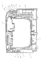
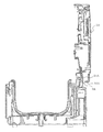
- FIG. 1 is a cross-sectional view of a rice cooker according to an embodiment of the present invention.
- the rice cooker 1 includes a rice cooker body 2 having an opening on the upper surface and a lid 3 that opens and closes the opening of the rice cooker body 2.
- the lid 3 is rotatably attached to the rice cooker body 2 by a hinge part 4 provided at the rear part of the rice cooker body 2.
- the hinge portion 4 includes a hinge rotation shaft 5 that pivotally supports the lid body 3 and a hinel spring 6 attached to the hinge rotation shaft 5. Has been granted.
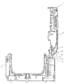
- the hinge portion 4 is provided with a stopper (not shown) for restricting the open end of the lid 3, and the state is maintained when the lid 3 is positioned at the open end. It has come to be.
- the inner pot 7 is housed inside the rice cooker body 2, and a heating coil 8 is provided below the inner pot 7 as a heating means for heating the inner pot 7.
- a latch mechanism 9 for opening and closing the lid 3 is provided on the front side in the rice cooker body 2, and a latch release button for releasing and engaging the latch mechanism 9 on the front exterior portion 20 of the rice cooker body 2. 10 is provided.
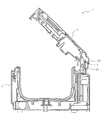
- the latch release button 10 is pushed, the latch mechanism 9 is disengaged, and the cover 3 moves the hinge rotation shaft 5 as shown in FIGS. 2 to 4 to be described later by the urging force of the hinge spring 6 of the hinge portion 4. It rotates to the open end as a center, and the opening of the rice cooker main body 2 is opened.
- FIG. 2 is a view showing a state in the middle of opening of the lid of FIG.
- FIG. 3 is a view showing a state where the lid of FIG. 1 is located at the open end.
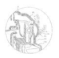
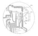
- FIG. 4 is an enlarged cross-sectional view of a main part of FIG. 1 and shows a change in the positional relationship between the exterior surface of the rear part of the hinge part and the rear exterior part of the lid body as the lid body is opened. As shown in FIGS. 2 to 4, when the lid 3 is opened, the rear exterior portion 30 of the lid 3 moves over the exterior surface 21 at the rear of the hinge portion as the lid 3 is opened.
- the exterior surface 21 at the rear portion of the hinge portion has a shape that bulges in an arc shape along the movement locus L of the rear exterior portion 30 of the lid 3.
- FIGS. 5 to 8 a conventional rice cooker is shown in FIGS.
- the gap SA between the rear exterior portion 30A of the lid 3A and the exterior surface 21A at the rear of the hinge portion temporarily expands as the lid 3A rotates (FIG. 6). , See FIG. 8), and then narrowed (see FIGS. 7 and 8), so that it is easy to pinch the fingers.
- a space portion 11 is formed below the hinge portion 4, and a control board 12 is disposed in the space portion 11.
- the exterior surface 21 of the hinge portion 4 has a shape that bulges in an arc shape, even if the rear position of the space portion 11 is expanded to at least the same depth position as the tip 21a of the bulged portion, The volume of the space 11 can be expanded without increasing the size of the main body 2.
- the rear portion of the space 11 is configured to be slightly behind the tip 21 a of the bulging portion.
- the exterior part upper surface 11a of the space part 11 is made into the inclined surface which inclines toward the downward direction. As shown in FIGS.
- the gap S ⁇ b> 1 between the rear exterior portion 30 of the lid 3 and the exterior top surface 11 a of the space 11 is widened in a state where the lid 3 is located at the open end. This is to ensure that the finger is not caught in the gap S1. Further, for the same reason, the lid is formed such that the lower surface 31 (see FIG. 4) of the rear exterior portion 30 of the lid 3 when the lid 3 is located at the open end is an inclined surface that is inclined upward. A rear exterior portion 30 of the body 3 is formed.
- the exterior surface 21 of the rear portion of the hinge portion is formed in a shape that bulges in an arc shape that is close to the movement locus L of the rear exterior portion 30 of the lid 3. Therefore, the gap S can be kept at a constant distance when the lid 3 is opened, and a finger can be prevented from being caught in the gap S.
- the space portion 11 is provided in the dead space below the hinge portion 4 and the control board 12 is provided in the space portion 11, the overall size can be reduced.
- the outer surface 11a of the space portion 11 is inclined to be inclined downward, the rear exterior portion 30 of the lid body 3 and the exterior portion of the space portion 11 in a state where the lid body 3 is positioned at the open end. It is possible to prevent a finger from being caught in the gap S1 between the upper surface 11a.
- the rear exterior portion 30 of the lid body 3 is formed so that the lower surface 31 of the rear exterior portion 30 of the lid body 3 is an inclined surface that is inclined upward when the lid body 3 is positioned at the open end. Therefore, it is possible to prevent a finger from being caught in the gap S1 between the rear exterior part 30 of the lid 3 and the exterior part upper surface 11a of the space part 11.
Landscapes
- Engineering & Computer Science (AREA)
- Food Science & Technology (AREA)
- Cookers (AREA)
- Air Filters, Heat-Exchange Apparatuses, And Housings Of Air-Conditioning Units (AREA)
Abstract
Description
炊飯器1は、上面に開口を有する炊飯器本体2と、この炊飯器本体2の開口を開閉する蓋体3とを備えている。蓋体3は、炊飯器本体2の後部に設けたヒンジ部4により炊飯器本体2に回動自在に取り付けられている。ヒンジ部4は、蓋体3を回動自在に軸支するヒンジ回転軸5と、ヒンジ回転軸5に装着されたヒネリバネ6とを有し、ヒネリバネ6により蓋体3に開放方向の付勢力が付与されている。なお、詳細図示していないが、ヒンジ部4には蓋体3の開放端を規制するストッパー(図示せず)が設けられており、蓋体3が開放端に位置した際、その状態が維持されるようになっている。
図2は、図1の蓋体の開放途中の状態を示した図である。図3は、図1の蓋体が開放端に位置した状態を示した図である。図4は、図1の要部拡大断面図で、蓋体の開放に伴うヒンジ部後部の外装面と蓋体の後部外装部との位置関係の変化を示す図である。
図2~図4に示すように、蓋体3を開いた際、蓋体3の開放に伴って蓋体3の後部外装部30がヒンジ部後部の外装面21を覆って移動する。このヒンジ部後部の外装面21は、蓋体3の後部外装部30の移動軌跡Lに近接して沿う円弧状に膨出した形状となっている。これにより、蓋体3の開放時、蓋体3の後部外装部30とヒンジ部後部の外装面21との間の隙間S(図4参照)が一定距離に保たれるため、この隙間Sに指が挟まるのを防止することができる。なお、この隙間Sは、当然のことながら指が挟まることがない距離に設定されている。
Claims (4)
- 炊飯器本体と、
前記炊飯器本体に設けたヒンジ部により前記炊飯器本体に回動自在に取り付けられた蓋体とを備え、
前記蓋体は、前記蓋体の開放時に前記ヒンジ部の外装面を覆って移動する外装部を有し、
前記炊飯器本体における前記ヒンジ部の外装面を、前記蓋体の前記外装部の移動軌跡に近接して沿う円弧状に膨出させた形状とした炊飯器。 - 前記炊飯器本体において前記ヒンジ部の下方に空間部を形成し、前記空間部内に制御基板を配置した請求項1記載の炊飯器。
- 前記炊飯器本体の前記空間部の外装部上面を下方に向けて傾斜する傾斜面とした請求項2記載の炊飯器。
- 前記蓋体が開放端に位置した状態のときの前記蓋体の前記外装部の下面が、上方に向けて傾斜する傾斜面となるように前記蓋体の前記外装部を形成した請求項2又は請求項3記載の炊飯器。
Priority Applications (4)
| Application Number | Priority Date | Filing Date | Title |
|---|---|---|---|
| CN201180030632.7A CN102946768B (zh) | 2010-06-23 | 2011-05-31 | 电饭煲 |
| KR1020127032347A KR101408428B1 (ko) | 2010-06-23 | 2011-05-31 | 취반기 |
| JP2012521279A JP5542929B2 (ja) | 2010-06-23 | 2011-05-31 | 炊飯器 |
| HK13109292.1A HK1181982B (en) | 2010-06-23 | 2011-05-31 | Rice cooker |
Applications Claiming Priority (2)
| Application Number | Priority Date | Filing Date | Title |
|---|---|---|---|
| JP2010142201 | 2010-06-23 | ||
| JP2010-142201 | 2010-06-23 |
Publications (1)
| Publication Number | Publication Date |
|---|---|
| WO2011161880A1 true WO2011161880A1 (ja) | 2011-12-29 |
Family
ID=45371088
Family Applications (1)
| Application Number | Title | Priority Date | Filing Date |
|---|---|---|---|
| PCT/JP2011/003043 Ceased WO2011161880A1 (ja) | 2010-06-23 | 2011-05-31 | 炊飯器 |
Country Status (5)
| Country | Link |
|---|---|
| JP (1) | JP5542929B2 (ja) |
| KR (1) | KR101408428B1 (ja) |
| CN (1) | CN102946768B (ja) |
| TW (1) | TWI441606B (ja) |
| WO (1) | WO2011161880A1 (ja) |
Cited By (1)
| Publication number | Priority date | Publication date | Assignee | Title |
|---|---|---|---|---|
| JP2016202439A (ja) * | 2015-04-20 | 2016-12-08 | 日立アプライアンス株式会社 | 洗濯機の開閉蓋および洗濯機 |
Families Citing this family (1)
| Publication number | Priority date | Publication date | Assignee | Title |
|---|---|---|---|---|
| JP5955462B2 (ja) * | 2013-06-12 | 2016-07-20 | 三菱電機株式会社 | 炊飯器 |
Citations (2)
| Publication number | Priority date | Publication date | Assignee | Title |
|---|---|---|---|---|
| JPH0421322U (ja) * | 1990-06-13 | 1992-02-24 | ||
| JP2000139694A (ja) * | 1998-11-09 | 2000-05-23 | Toshiba Home Technology Corp | 炊飯器 |
Family Cites Families (4)
| Publication number | Priority date | Publication date | Assignee | Title |
|---|---|---|---|---|
| JPS5980527U (ja) * | 1982-11-17 | 1984-05-31 | 株式会社銭高組 | 地盤改良装置 |
| JP2002204746A (ja) * | 2001-01-12 | 2002-07-23 | Matsushita Electric Ind Co Ltd | 炊飯器 |
| CN201019528Y (zh) * | 2007-03-06 | 2008-02-13 | 冼新全 | 一种带翻盖机构的电压力锅 |
| CN101692958B (zh) * | 2009-10-19 | 2012-05-09 | 钱海鹏 | 烹饪装置 |
-
2011
- 2011-05-31 WO PCT/JP2011/003043 patent/WO2011161880A1/ja not_active Ceased
- 2011-05-31 KR KR1020127032347A patent/KR101408428B1/ko not_active Expired - Fee Related
- 2011-05-31 CN CN201180030632.7A patent/CN102946768B/zh not_active Expired - Fee Related
- 2011-05-31 JP JP2012521279A patent/JP5542929B2/ja not_active Expired - Fee Related
- 2011-06-01 TW TW100119171A patent/TWI441606B/zh not_active IP Right Cessation
Patent Citations (2)
| Publication number | Priority date | Publication date | Assignee | Title |
|---|---|---|---|---|
| JPH0421322U (ja) * | 1990-06-13 | 1992-02-24 | ||
| JP2000139694A (ja) * | 1998-11-09 | 2000-05-23 | Toshiba Home Technology Corp | 炊飯器 |
Cited By (1)
| Publication number | Priority date | Publication date | Assignee | Title |
|---|---|---|---|---|
| JP2016202439A (ja) * | 2015-04-20 | 2016-12-08 | 日立アプライアンス株式会社 | 洗濯機の開閉蓋および洗濯機 |
Also Published As
| Publication number | Publication date |
|---|---|
| JP5542929B2 (ja) | 2014-07-09 |
| TW201200077A (en) | 2012-01-01 |
| TWI441606B (zh) | 2014-06-21 |
| JPWO2011161880A1 (ja) | 2013-08-19 |
| CN102946768A (zh) | 2013-02-27 |
| CN102946768B (zh) | 2015-09-16 |
| KR101408428B1 (ko) | 2014-06-17 |
| HK1181982A1 (en) | 2013-11-22 |
| KR20130038275A (ko) | 2013-04-17 |
Similar Documents
| Publication | Publication Date | Title |
|---|---|---|
| EP3088260B1 (en) | Pop-up hood device for vehicle | |
| JP5542929B2 (ja) | 炊飯器 | |
| JP2008125965A (ja) | 液体容器 | |
| JP5764223B2 (ja) | 車両用ドア | |
| HK1181982B (en) | Rice cooker | |
| JP5456374B2 (ja) | 注出キャップ | |
| JP5219043B2 (ja) | アシスト機構付引手 | |
| JP7548254B2 (ja) | 車両のドアハンドル | |
| JP4457078B2 (ja) | 高周波加熱装置 | |
| JP6737695B2 (ja) | ヒンジキャップ | |
| JP2008229150A (ja) | 電気炊飯器 | |
| JP6490977B2 (ja) | インサイドドアハンドル構造 | |
| JP5219153B2 (ja) | サッシ窓及びこれに用いられるキャップ材 | |
| JP5659596B2 (ja) | 電気炊飯器 | |
| JP6805855B2 (ja) | ドア開度固定装置 | |
| JP5053192B2 (ja) | アシスト機構付引手及びサッシ窓 | |
| JP2012021301A (ja) | ダンパー機能付き蝶番 | |
| JP2010077706A (ja) | カバー開閉機構 | |
| JP6596722B2 (ja) | トランクリッド開閉機構 | |
| KR102462686B1 (ko) | 밥솥 | |
| JP2012145314A (ja) | 加熱調理器 | |
| JP2007240149A (ja) | 調理器 | |
| JP7235197B2 (ja) | 便座装置 | |
| CN208639045U (zh) | 侧排口盖板弹簧舌片锁闭机构 | |
| JP7296194B2 (ja) | 開き窓 |
Legal Events
| Date | Code | Title | Description |
|---|---|---|---|
| WWE | Wipo information: entry into national phase |
Ref document number: 201180030632.7 Country of ref document: CN |
|
| 121 | Ep: the epo has been informed by wipo that ep was designated in this application |
Ref document number: 11797769 Country of ref document: EP Kind code of ref document: A1 |
|
| WWE | Wipo information: entry into national phase |
Ref document number: 2012521279 Country of ref document: JP |
|
| ENP | Entry into the national phase |
Ref document number: 20127032347 Country of ref document: KR Kind code of ref document: A |
|
| NENP | Non-entry into the national phase |
Ref country code: DE |
|
| 122 | Ep: pct application non-entry in european phase |
Ref document number: 11797769 Country of ref document: EP Kind code of ref document: A1 |