WO2011158744A1 - レンズ鏡胴およびレンズ鏡胴組立方法 - Google Patents
レンズ鏡胴およびレンズ鏡胴組立方法 Download PDFInfo
- Publication number
- WO2011158744A1 WO2011158744A1 PCT/JP2011/063341 JP2011063341W WO2011158744A1 WO 2011158744 A1 WO2011158744 A1 WO 2011158744A1 JP 2011063341 W JP2011063341 W JP 2011063341W WO 2011158744 A1 WO2011158744 A1 WO 2011158744A1
- Authority
- WO
- WIPO (PCT)
- Prior art keywords
- lens
- end side
- lenses
- lens frame
- rear end
- Prior art date
- Legal status (The legal status is an assumption and is not a legal conclusion. Google has not performed a legal analysis and makes no representation as to the accuracy of the status listed.)
- Ceased
Links
Images



Classifications
-
- G—PHYSICS
- G02—OPTICS
- G02B—OPTICAL ELEMENTS, SYSTEMS OR APPARATUS
- G02B7/00—Mountings, adjusting means, or light-tight connections, for optical elements
- G02B7/02—Mountings, adjusting means, or light-tight connections, for optical elements for lenses
- G02B7/021—Mountings, adjusting means, or light-tight connections, for optical elements for lenses for more than one lens
Definitions
- the present invention relates to a lens barrel and a lens barrel assembling method.
- a lens barrel in which a plurality of lenses are housed in a lens frame is generally used for a camera-equipped mobile phone camera or a vehicle-mounted camera.
- Devices equipped with this lens barrel are often used in environments where temperature and humidity change. For example, an in-vehicle camera is exposed to a high temperature or a low temperature. Therefore, this lens barrel is required to have very high reliability, that is, performance stability and durability under severe environmental conditions such as high temperature / low temperature and temperature shock.
- the clearance between the lens outer diameter and the lens frame inner diameter in a lens barrel in which a plurality of lenses are housed in a lens frame is generally a clearance of 20 ⁇ m or less so as not to cause a decrease in optical performance due to lens misalignment after assembly. Tolerance management is performed so that
- the lens is made of glass and the lens frame is made of ceramic
- the lens when the lens is incorporated into the lens frame, the lens is inserted in a posture in which the center is shifted or tilted. There is a risk of rubbing. Then, considering that the tolerance is controlled so that the clearance between the lens outer diameter and the lens frame inner diameter is 20 ⁇ m or less, it is extremely difficult to avoid such rubbing. Since both the glass lens and the ceramic lens frame are hard materials, scraping occurs when they are rubbed, and the scraping residue adversely affects the optical performance in the assembled lens barrel. .
- the present invention avoids the generation of scraped debris during assembly, and in the assembled lens barrel, a lens barrel and a lens in which optical performance is prevented from deteriorating due to the scraped debris.
- An object of the present invention is to provide a lens barrel assembling method.
- the first lens barrel of the lens barrel of the present invention that achieves the above object opens to both the plurality of lenses and the front end portion and the rear end portion in the optical axis direction, and accommodates the plurality of lenses.
- a hollow is formed, and has an inner surface, an outer surface, and a rear end side lens pressing portion that presses a peripheral edge portion of the rear end side surface of the rear end side lens disposed on the rearmost end side of the plurality of lenses.
- a lens frame extending from the front end toward the rear end side to a position where a part of the rear end side is left, having a groove penetrating the inner surface and the outer surface, and supported by the lens frame, A pressing ring for pressing a peripheral portion of a front end side surface of a front end side lens provided on the front end side among the plurality of lenses housed in the lens frame is provided.
- the front end and the rear end in the optical axis direction in the present invention distinguish one from the other at both ends in the optical axis direction. That is, the front end side and the rear end side include both cases corresponding to the subject side and the imaging side, and conversely, cases corresponding to the imaging side and the subject side, respectively.
- the first lens barrel of the lens barrel of the present invention is a lens frame in which a hollow that accommodates a plurality of lenses is formed, and a groove is formed through the inner surface and the outer surface.
- the groove extends from the front end toward the rear end side to a position where a part of the rear end side is left. Therefore, according to the first lens barrel, by forming the lens frame such that the openings at both ends in the optical axis direction are equal to or slightly smaller than the diameters of the plurality of lenses, At the time of assembling the lens barrel, the plurality of lenses can be fixed in the lens frame by placing the lenses in the lens frame in a state where the grooves are expanded and then returning the lenses.
- the lens frame when the lens barrel is assembled, the lens frame is formed so that the openings at both ends in the optical axis direction have a diameter larger than the diameter of each of the plurality of lenses.
- the plurality of lenses can be fixed in the lens frame by attaching the holding ring to the lens frame so as to compress the opening on the front end side of the lens frame after accommodating the plurality of lenses in the lens frame. Therefore, according to the first lens barrel, when a plurality of lenses are accommodated in the lens frame, it is avoided that the two are rubbed and scraped off. For this reason, it is possible to prevent the optical performance from being deteriorated due to the scraped residue.
- the second lens barrel of the lens barrel of the present invention that achieves the above object opens to both the plurality of lenses and the front end portion and the rear end portion in the optical axis direction.
- a hollow for housing is formed, and an inner surface, an outer surface, and a rear end side lens pressing portion that presses a peripheral edge portion of a rear end side surface of the rear end side lens disposed on the rearmost end side of the plurality of lenses.
- a lens frame that extends from the front end toward the rear end toward the rear end and has a groove penetrating the inner surface and the outer surface, and is supported by the lens frame and accommodated in the lens frame.
- a pressing ring for pressing a peripheral portion of a front end side surface of a front end side lens disposed on the foremost end side of the plurality of lenses is provided.
- the second lens barrel of the lens barrel of the present invention is a lens frame in which a hollow that accommodates a plurality of lenses is formed, and a groove is formed through the inner surface and the outer surface.
- the groove extends from the front end toward the rear end toward the rear end. Therefore, according to the second lens barrel, by forming the lens frame such that the openings at both ends in the optical axis direction are equal to or slightly smaller than the diameters of the plurality of lenses, At the time of assembling the lens barrel, the plurality of lenses can be fixed in the lens frame by placing the lenses in the lens frame in a state where the grooves are expanded and then returning the lenses.
- the second lens barrel when a plurality of lenses are accommodated in the lens frame, it is avoided that the two are rubbed and scraped off. For this reason, it is possible to prevent the optical performance from being deteriorated due to the scraped residue.
- the end portion on the rear end side of the groove has a rounded corner shape.
- the lens frame is preferably made of ceramic.
- the lens barrel of the present invention is also preferably provided with a covering member that covers the groove.
- the lens barrel of the present invention further includes a space ring disposed between adjacent lenses in the plurality of lenses and housed in the lens frame together with the plurality of lenses.
- the position of each of the plurality of lenses in the optical axis direction can be determined reliably.
- a first lens barrel assembling method of the lens barrel assembling method of the present invention that achieves the above object opens at both the front end portion and the rear end portion in the optical axis direction and accommodates a plurality of lenses.
- a hollow is formed, and has an inner surface, an outer surface, and a rear end side lens pressing portion that presses a peripheral edge portion of the rear end side surface of the rear end side lens disposed on the rearmost end side of the plurality of lenses. Further, this groove of the lens frame that extends from the front end toward the rear end side to a position where a part of the rear end side is left and that penetrates the inner surface and the outer surface is expanded and expanded.
- the plurality of lenses are accommodated in the lens frame in a state of being released, the groove of the lens frame is released, and the lens frame is disposed on the front end side of the plurality of lenses accommodated in the lens frame. Hold the retaining ring that holds the peripheral edge of the front-end surface of the front-end lens. Characterized in that attached to the serial lens frame.
- a first lens barrel assembling method of the lens barrel assembling method according to the present invention includes a lens frame in which openings at both ends in the optical axis direction are equal to or slightly smaller than the diameters of a plurality of lenses.
- the first lens barrel assembling method fixes the plurality of lenses in the lens frame by releasing the expansion after accommodating the plurality of lenses in the lens frame in a state where the groove is expanded. This is an assembly method. Therefore, according to the first lens barrel assembling method, when a plurality of lenses are accommodated in the lens frame, it is possible to avoid scraping and scraping both of them to generate debris. For this reason, in the assembled lens barrel, it is possible to prevent the optical performance from being deteriorated due to the scraped residue.
- the second lens barrel assembling method of the lens barrel assembling method of the present invention that achieves the above object is opened at both the front end portion and the rear end portion in the optical axis direction and accommodates a plurality of lenses.
- a hollow is formed, and has an inner surface, an outer surface, and a rear end side lens pressing portion that presses a peripheral edge portion of the rear end side surface of the rear end side lens disposed on the rearmost end side of the plurality of lenses.
- the plurality of lenses are accommodated in a lens frame extending from the front end toward the rear end side to a position where a part of the rear end side is left and having a groove penetrating the inner surface and the outer surface.
- the second lens barrel assembling method of the lens barrel assembling method of the present invention is an assembling method using a lens frame in which the opening at both ends in the optical axis direction has a diameter larger than the diameter of each of the plurality of lenses.
- the plurality of lenses are accommodated by attaching the holding ring to the lens frame so as to compress the opening on the front end side of the lens frame after accommodating the plurality of lenses in the lens frame.
- a third lens barrel assembling method of the lens barrel assembling method of the present invention that achieves the above object opens at both the front end portion and the rear end portion in the optical axis direction and accommodates a plurality of lenses.
- a hollow is formed, and has an inner surface, an outer surface, and a rear end side lens pressing portion that presses a peripheral edge portion of the rear end side surface of the rear end side lens disposed on the rearmost end side of the plurality of lenses.
- the groove of the lens frame that extends from the front end toward the rear end toward the rear end and has a groove penetrating the inner surface and the outer surface is expanded and the lens frame in the expanded state is inserted into the lens frame.
- a third lens barrel assembling method of the lens barrel assembling method according to the present invention includes a lens frame in which openings at both ends in the optical axis direction are equal to or slightly smaller than the diameters of a plurality of lenses.
- the third lens barrel assembling method fixes the plurality of lenses in the lens frame by releasing the expansion after accommodating the plurality of lenses in the lens frame in a state where the groove is expanded. This is an assembly method. Therefore, according to the third lens barrel assembling method, when a plurality of lenses are accommodated in the lens frame, it is possible to avoid scraping and scraping both of them to generate debris. For this reason, in the assembled lens barrel, it is possible to prevent the optical performance from being deteriorated due to the scraped residue.
- a fourth lens barrel assembling method of the lens barrel assembling method of the present invention that achieves the above object opens at both the front end portion and the rear end portion in the optical axis direction and accommodates a plurality of lenses.
- a hollow is formed, and has an inner surface, an outer surface, and a rear end side lens pressing portion that presses a peripheral edge portion of the rear end side surface of the rear end side lens disposed on the rearmost end side of the plurality of lenses. Further, this groove of the lens frame that extends from the front end toward the rear end side to a position where a part of the rear end side is left and that penetrates the inner surface and the outer surface is expanded and expanded.
- the plurality of lenses are accommodated in the lens frame in a state in which the lens frame is accommodated, and the opening of the groove on the lens frame is released, and the opening on the front end side of the lens frame is accommodated in the lens frame.
- the front end disposed on the foremost end side of the plurality of lenses
- the retainer ring for holding the peripheral portion of the surface of the front side of the lens, characterized in that attached to the lens frame.
- the fourth lens barrel assembling method of the lens barrel assembling method of the present invention is capable of absorbing a larger dimensional tolerance of the lens frame because the lens frame is expanded and then compressed after inserting the lens and the interval ring. Become.
- the lens barrel assembling method of the present invention further covers the groove with a covering member.
- a lens barrel and a lens barrel assembly in which generation of scraps during assembly is avoided and optical performance is prevented from being deteriorated due to the scraps in the assembled lens barrel.
- FIG. 6 is a perspective view illustrating a method for assembling the lens barrel 100.
- FIG. 5 is a perspective view illustrating a method for assembling the lens barrel 200. It is the figure which looked at the lens barrel 200 of FIG. 8 from the to-be-photographed object side.
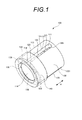
- FIG. 1 is a perspective view showing a lens barrel 100, which is a first embodiment of the lens barrel of the present invention, as viewed obliquely from the subject side.
- 2 is a longitudinal sectional view parallel to the optical axis direction of the lens barrel 100 shown in FIG.
- the lens barrel 100 of the first embodiment includes four lenses 111, 112, 113, 114, three spacing rings 121, 122, 123, a lens frame 130, and a presser. Ring 140.
- the four lenses 111, 112, 113, and 114 are glass lenses, and their optical axes are in order of the first lens 111, the second lens 112, the third lens 113, and the fourth lens 114 from the imaging side. It is arranged to overlap.
- Each of the lenses 111, 112, 113, and 114 has a disk shape, and the outer diameter (side surface) is not polished and has a slit surface of # 1000 or less. Since the side surface is a ground surface, adverse effects such as ghost are suppressed. The side surface is preferably # 300 or less for ease of processing.
- These four lenses 111, 112, 113, and 114 correspond to an example of a plurality of lenses according to the present invention.
- the subject side corresponds to an example of the front end side in the optical axis direction according to the present invention
- the imaging side corresponds to an example of the rear end side in the optical axis direction according to the present invention
- the first lens 111 of these four lenses 111, 112, 113, 114 corresponds to an example of the rear end side lens referred to in the present invention
- the fourth lens 114 corresponds to the front end referred to in the present invention. This corresponds to an example of a side lens.
- the three spacing rings 121, 122, 123 are arranged between adjacent lenses in the four lenses 111, 112, 113, 114. That is, the first spacing ring 121 is disposed between the first lens 111 and the second lens 112, the second spacing ring 122 is disposed between the second lens 112 and the third lens 113, and the third lens 113. A third spacing ring 123 is disposed between the first lens 114 and the fourth lens 114. Each of these three spacing rings 121, 122, 123 corresponds to an example of a spacing ring referred to in the present invention.
- the lens frame 130 is a porous ceramic member having a hardness higher than the hardness of the four lenses 111, 112, 113, 114.
- the lens frame 130 is open at both ends in the direction of the arrow A, which is the optical axis direction, and is formed with a hollow that accommodates the four lenses 111, 112, 113, 114 and the three spacing rings 121, 122, 123. 131 and an outer surface 132.
- the lens frame 130 includes an imaging-side lens holder that holds down the peripheral portion 1111 of the imaging-side surface of the first lens 111 disposed on the most imaging side of the four lenses 111, 112, 113, and 114. Part 133.
- the lens frame 130 has three grooves 135 extending through the inner surface 131 and the outer surface 132 extending from the subject-side front end 134 to the position where a part of the imaging side is left toward the imaging side. It is formed intermittently.
- the width of each of these three grooves 135 is preferably 0.1 mm or more and 0.5 mm or less, for example.
- the imaging side end portion 1351 of each of the three grooves 135 has a rounded round shape. For this reason, when the lens barrel 100 is assembled, even if the groove 135 is expanded or the object side opening of the lens frame 130 is compressed, the imaging side end 1351 of the groove 135 is broken by the stress concentration. Is avoided.
- the radius of the rounded shape is preferably 0.1 mm or more and 0.3 mm or less, for example.
- three jig insertion grooves 138 extending from the subject-side front end 134 to the middle toward the imaging side are provided.
- the jig insertion groove 138 is a groove for temporarily inserting a jig when the lens barrel 100 is assembled.
- Each of the three jig insertion grooves 138 is disposed between the three grooves 135 described above.
- the lens frame 130 corresponds to an example of a lens frame according to the present invention.
- a ceramic member can be used for the spacing rings 121, 122, and 123 described above, as in the case of the lens frame 130, and resin or glass can also be used.
- the holding ring 140 is a ceramic member made of the same material as the lens frame 130, for example, and has a substantially cylindrical shape. One open end has a shape protruding toward the center of the cylinder. Further, the holding ring 140 is supported by the lens frame 130. More specifically, the holding ring 140 covers the end of the lens frame 130 on the subject side and is fixed to the lens frame 130.
- the pressing ring 140 may be fixed to the lens frame 130 by adhesion, or may be screw fixing by providing a thread on the inner periphery of the pressing ring 140 and the outer surface 132 of the lens frame 130. Also good.
- the holding ring 140 has a peripheral portion 1141 on the subject side surface of the fourth lens 114 provided on the most subject side of the four lenses 111, 112, 113, 114 accommodated in the lens frame 130. Holding down. That is, the four lenses 111, 112, 113, 114 and the three spacing rings 121, 122, 123 are sandwiched between the imaging side lens pressing portion 133 and the pressing ring 140 of the lens frame 130.
- This presser ring 140 corresponds to an example of a presser ring according to the present invention.
- the positions of the four lenses 111, 112, 113, 114 accommodated in the lens frame 130 in the direction of the arrow A, which is the optical axis direction, are the imaging side lens pressing portion. 133, three spacing rings 121, 122, 123 and a holding ring 140.
- the lenses 111, 112, 113, 114 are made of glass and have a hardness of HV300 to 800.
- the lens frame 130 and the holding ring 140 are made of ceramic and have a hardness of HV2600 or less.
- the hardness of the lens frame 130 and the holding ring 140 is preferably HV500 or more and 2600 or less from the viewpoint of impact resistance.
- the hardness is expressed by the numerical value of Vickers hardness (HV), but this numerical value is almost the same even if it is Knoop hardness (Hk).
- the optical performance is deteriorated due to the axial misalignment of the lens between the outer diameter of each of the four lenses 111, 112, 113, 114 and the inner surface 131 of the lens frame 130.
- tolerance control is performed so that a clearance of 20 ⁇ m or less, preferably a clearance of 10 ⁇ m or less, is obtained when the holding ring 140 is fixed to the lens frame 130.
- a lens frame 130 in which a hollow that accommodates four lenses 111, 112, 113, 114 and three spacing rings 121, 122, 123 is formed has an inner surface 131 and an outer surface 132. Are formed intermittently in the circumferential direction, and the grooves 135 extend from the subject-side front end 134 toward the imaging side to a position where a part of the imaging side remains. ing. Therefore, according to the lens barrel 100 of the first embodiment, the openings at both ends in the direction of the arrow A that is the optical axis direction are the diameters of the four lenses 111, 112, 113, 114 and the three spacing rings 121, 122, 123, respectively.
- the lens frame 130 is formed so as to have a diameter that is equal to or slightly smaller than the diameter of the lens barrel 100, so that when the lens barrel 100 is assembled, the groove 135 is pushed into the lens frame 130 in a state where the groove 135 is expanded.
- the four lenses 111, 112, 113, 114 and the three spacing rings 121, 122, 123 are accommodated and then returned to their original positions, whereby the four lenses 111, 112, 113, 114 and the three spacing rings 121, 122, 123 are restored. Can be fixed in the lens frame 130.
- the openings at both ends in the direction of the arrow A that is the optical axis direction are the diameters of the four lenses 111, 112, 113, 114 and the three spacing rings 121, 122, 123, respectively.
- the lens frame 130 By forming the lens frame 130 so as to have a larger diameter, when the lens barrel 100 is assembled, the four lenses 111, 112, 113, 114 and the three spacing rings 121, 122 are included in the lens frame 130.
- the holding ring 140 is attached to the lens frame 130 so as to compress the subject-side opening of the lens frame 130, so that the four lenses 111, 112, 113, 114 and the three spacing rings 121, 122, 123 can be fixed in the lens frame 130. Therefore, according to the lens barrel 100 of the first embodiment, when the four lenses 111, 112, 113, 114 and the three spacing rings 121, 122, 123 are accommodated in the lens frame 130, both are rubbed. Generation of scraps is avoided. For this reason, it is possible to prevent the optical performance from being deteriorated due to the scraped residue. A method for assembling the lens barrel 100 will be described later.
- the lens barrel 100 of the first embodiment described above is further provided with a covering member.
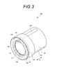
- FIG. 3 is a perspective view showing a lens barrel 200, which is a second embodiment of the lens barrel of the present invention, viewed obliquely from the subject side.
- the lens barrel 200 of the second embodiment includes four lenses 111, 112, 113, 114, three spacing rings 121, 122, 123, a lens frame 130, and a holding ring 140. And a covering member 250.
- the covering member 250 covers the groove 135 formed in the lens frame 130.
- This covering member 250 corresponds to an example of the covering member according to the present invention.
- the lens barrel 200 of the second embodiment as with the lens barrel 100 of the first embodiment, four lenses 111, 112, 113, 114 and three spacing rings 121, 122, When 123 is accommodated, it is avoided that both scrape and scrap and scrap is generated. For this reason, it is possible to prevent the optical performance from being deteriorated due to the scraped residue. Furthermore, according to the lens barrel 200 of the second embodiment, the light shielding property and the dustproof property are ensured by the covering member 250 that covers the groove 135 formed in the lens frame 130. A method for assembling the lens barrel 200 will be described later.
- the lens frame is different from the first embodiment described above.
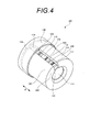
- FIG. 4 is a perspective view showing a lens barrel 300, which is a third embodiment of the lens barrel of the present invention, viewed obliquely from the imaging side.
- FIG. 5 is a longitudinal sectional view parallel to the optical axis direction of the lens barrel 300 shown in FIG.
- the lens barrel 300 of the third embodiment includes four lenses 111, 112, 113, 114, three spacing rings 121, 122, 123, a lens frame 330, and a presser. Ring 140.
- the lens frame 330 penetrates through the inner surface 131 and the outer surface 132 extending from the subject side front end 134 toward the image formation side rear end 336 in place of the three grooves 135 in the first embodiment.
- One groove 335 is formed.
- the width of the groove 335 is preferably 0.1 mm or more and 0.5 mm or less, for example.
- the inner surface 131 of the lens frame 330 is provided with three jig insertion grooves (not shown) extending from the subject-side front end 134 halfway toward the imaging side.
- the jig insertion groove is a groove for temporarily inserting a jig when the lens barrel 100 is assembled.
- Each of the three jig insertion grooves is intermittently arranged in the circumferential direction.
- the lens frame 330 corresponds to an example of a lens frame according to the present invention.
- the positions of the four lenses 111, 112, 113, 114 accommodated in the lens frame 330 in the direction of the arrow A, which is the optical axis direction, are the imaging side lens pressing portion. 133, three spacing rings 121, 122, 123 and a holding ring 140.
- a decrease in optical performance due to axial misalignment of the lens between the outer diameter of each of the four lenses 111, 112, 113, 114 and the inner surface 131 of the lens frame 330 is performed so that a clearance of 20 ⁇ m or less, preferably a clearance of 10 ⁇ m or less is obtained in a state where the press ring 140 is fixed to the lens frame 330.
- a lens frame 330 in which a hollow that accommodates four lenses 111, 112, 113, 114 and three spacing rings 121, 122, 123 is formed has an inner surface 131 and an outer surface 132.
- the groove 335 extends from the subject-side front end 134 toward the imaging side rear end 336 toward the imaging side rear end 336. Therefore, according to the lens barrel 300 of the third embodiment, the openings at both ends in the direction of the arrow A that is the optical axis direction are the diameters of the four lenses 111, 112, 113, 114 and the three spacing rings 121, 122, 123.
- the lens frame 330 is formed so as to have a diameter that is equal to or slightly smaller than the diameter of the lens barrel 300, so that when the lens barrel 300 is assembled, the groove 335 is pushed into the lens frame 330 in a state where the groove 335 is expanded.
- the four lenses 111, 112, 113, 114 and the three spacing rings 121, 122, 123 are accommodated and then returned to their original positions, whereby the four lenses 111, 112, 113, 114 and the three spacing rings 121, 122, 123 are restored. Can be fixed in the lens frame 330.
- the lens barrel 300 of the third embodiment when the four lenses 111, 112, 113, 114 and the three spacing rings 121, 122, 123 are accommodated in the lens frame 330, both are rubbed. Generation of scraps is avoided. For this reason, it is possible to prevent the optical performance from being deteriorated due to the scraped residue.
- the lens barrel 300 according to the third embodiment may be provided with a covering member that covers the groove 335 as in the lens barrel 200 according to the second embodiment. A method for assembling the lens barrel 300 will be described later.
- the first embodiment described below is an assembling method of the lens barrel 100 described with reference to FIGS.
- This assembling method can also be applied as the assembling method of the lens barrel 200 described with reference to FIG. 3, but here, the assembling method of the lens barrel 100 will be described.
- the components of the lens barrel 100 will be denoted by the same reference numerals, and the description thereof will be omitted. Only the method of assembling the lens barrel 100 (see FIGS. 1 and 2) will be described.
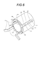
- FIG. 6 is a perspective view for explaining an assembling method of the lens barrel 100
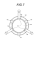
- FIG. 7 is a view of the lens barrel 100 of FIG. 6 as viewed from the subject side.
- a lens frame in which the openings at both ends in the direction of the arrow A, which is the optical axis direction, are equal to or slightly smaller than the diameters of the four lenses 111, 112, 113, 114 and the three spacing rings 121, 122, 123. 130 grooves 135 are pushed out.
- the jig J1 is inserted into the three jig insertion grooves 138 of the lens frame 130, and the lens frame 130 is spread from the inside toward the outside by the jig J1.
- the amount of enlargement of the inner diameter of the lens frame 130 by expanding the groove 135 of the lens frame 130 is, for example, 0.01 mm or more, preferably around 0.1 mm.
- the four lenses 111, 112, 113, 114 and the three spacing rings 121, 122, 123 are accommodated in the lens frame 130 in the expanded state.
- the thickness of the part inserted into the jig insertion groove 138 of the jig J1 is formed thinner than the height of the jig insertion groove 138, and the four lenses 111, 112, 113, 114 with respect to the jig J1 are formed. And contact of the three spacing rings 121, 122, 123 is avoided.
- the holding ring 140 is attached to the lens frame 130, and the peripheral portion 1141 of the subject side surface of the fourth lens 114 provided on the most subject side of the four lenses 111, 112, 113, 114 is pressed.
- the four lenses 111, 112, 113, 114 and the three spacing rings 121, 122, 123 are sandwiched between the imaging side lens pressing portion 133 and the pressing ring 140 of the lens frame 130, and the lens frame Fixed within 130.
- the four lenses 111, 112, 113, 114 and the three spacing rings 121, 122, 123 are accommodated in the lens frame 130 in a state where the groove 135 is expanded.
- This is an assembly method in which the four lenses 111, 112, 113, 114 and the three spacing rings 121, 122, 123 are fixed in the lens frame 130 by returning to the original later. Therefore, according to the lens barrel assembling method of the first embodiment, when the four lenses 111, 112, 113, 114 and the three spacing rings 121, 122, 123 are accommodated in the lens frame 130, both are rubbed. As a result, the generation of scraps is avoided. For this reason, in the assembled lens barrel 100, it is possible to prevent the optical performance from being deteriorated due to shaving residue.
- the second embodiment described below is an assembling method of the lens barrel 200 described with reference to FIG. Although this assembling method can be applied as the assembling method of the lens barrel 100 described with reference to FIGS. 1 and 2, the assembling method of the lens barrel 200 will be described here.
- the components of the lens barrel 200 are denoted by the same reference numerals and the description thereof is omitted, and only the method of assembling the lens barrel 200 (see FIG. 3) will be described.
- the lens frame 130 having openings larger than the diameters of the four lenses 111, 112, 113, 114 and the three spacing rings 121, 122, 123 at the both ends in the arrow A direction that is the optical axis direction.
- One lens 111, 112, 113, 114 and three spacing rings 121, 122, 123 are accommodated.
- the holding ring 140 is attached to the lens frame 130 so as to compress the subject side opening of the lens frame 130, and the fourth lens 114 disposed on the most subject side of the four lenses 111, 112, 113, 114.
- the peripheral portion 1141 of the surface on the subject side is pressed.
- FIG. 8 is a perspective view for explaining an assembling method of the lens barrel 200
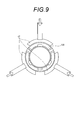
- FIG. 9 is a view of the lens barrel 200 of FIG. 8 as viewed from the subject side.
- the holding ring 140 when attaching the holding ring 140 (see FIG. 3) to the lens frame 130, as shown in FIGS. 8 and 9, the jig J2 is pressed against the outside of the lens frame 130 from three directions, and the lens frame By applying a load from the outside to the inside, the subject side opening of the lens frame 130 is compressed. In this compressed state, the holding ring 140 (see FIG. 3) is attached to the lens frame 130. Even after the jig J2 is removed, the pressed state of the lens frame 130 is held by the holding ring 140.
- the groove 135 formed in the lens frame 130 is covered with the covering member 250.
- the four lenses 111, 112, 113, 114 and the three spacing rings 121, 122, 123 are sandwiched between the imaging side lens pressing portion 133 and the pressing ring 140 of the lens frame 130, and the lens frame Fixed within 130.
- the lens barrel assembling method of the second embodiment after the four lenses 111, 112, 113, 114 and the three spacing rings 121, 122, 123 are accommodated in the lens frame 130, the object side opening of the lens frame 130 is opened.
- this assembling method four lenses 111, 112, 113, 114 and three spacing rings 121, 122, 123 are fixed in the lens frame 130 by attaching the holding ring 140 to the lens frame 130 so as to be compressed. Therefore, according to the lens barrel assembling method of the second embodiment, when the four lenses 111, 112, 113, 114 and the three spacing rings 121, 122, 123 are accommodated in the lens 130 frame, both are rubbed. As a result, the generation of scraps is avoided.
- the lens barrel assembling method of the second embodiment the light shielding property and the dustproof property are ensured by the covering member 250 covering the groove 135.
- the third embodiment described below is an assembling method of the lens barrel 300 described with reference to FIGS.
- the components of the lens barrel 300 are denoted by the same reference numerals, and the description thereof is omitted. Only the assembling method of the lens barrel 300 (see FIGS. 4 and 5) will be described.
- the openings at both ends in the direction of the arrow A which is the optical axis direction, have diameters that are equal to or slightly smaller than the diameters of the four lenses 111, 112, 113, 114 and the three spacing rings 121, 122, 123, respectively.
- the groove 335 of the lens frame 330 is pushed wide. Specifically, a jig J1 similar to the jig J1 described with reference to FIGS. 6 and 7 is inserted into the three jig insertion grooves of the lens frame 330, and the lens frame 330 is attached by the jig J1. Spread from the inside to the outside. Note that the inner diameter enlargement amount of the lens frame 330 by pushing and expanding the groove 335 of the lens frame 330 is, for example, 0.01 mm or more, and preferably around 0.1 mm.
- the four lenses 111, 112, 113, 114 and the three spacing rings 121, 122, 123 are accommodated in the lens frame 330 in the pushed state.
- the thickness of the portion inserted into the jig insertion groove of the jig J1 is formed thinner than the height of the jig insertion groove, and the four lenses 111, 112, 113, 114, and 3 with respect to the jig J1 are formed. Contact between the two spacing rings 121, 122, 123 is avoided.
- the holding ring 140 is attached to the lens frame 330, and the peripheral portion 1141 of the subject side surface of the fourth lens 114 provided on the most subject side of the four lenses 111, 112, 113, 114 is pressed.
- the four lenses 111, 112, 113, 114 and the three spacing rings 121, 122, 123 are sandwiched between the image forming side lens pressing portion 133 and the pressing ring 140 of the lens frame 330, and the lens frame. Fixed within 330.
- the four lenses 111, 112, 113, 114 and the three spacing rings 121, 122, 123 are accommodated in the lens frame 330 in a state where the groove 335 is expanded.
- This is an assembly method in which the four lenses 111, 112, 113, 114 and the three spacing rings 121, 122, 123 are fixed in the lens frame 330 by returning to the original later. Therefore, according to the lens barrel assembling method of the third embodiment, when the four lenses 111, 112, 113, 114 and the three spacing rings 121, 122, 123 are accommodated in the lens frame 330, both are rubbed. As a result, the generation of scraps is avoided. For this reason, in the assembled lens barrel 300, it is possible to prevent the optical performance from being deteriorated due to the scraped residue.
- the lens and the spacing ring are inserted in a state where the lens frame 130 is expanded from the inside to the outside.
- the lens and the spacing ring are inserted. After the lens frame 130 is inserted, the lens frame 130 is pressed and shrunk.
- the lens and the interval ring are inserted with the lens frame 130 widened from the inside to the outside, The lens frame 130 is pushed and shrunk by the ring 140.
- the jig J1 is inserted into the three jig insertion grooves 138 of the lens frame 130.
- the lens frame 130 is expanded from the inside toward the outside by the jig J1.
- the four lenses 111, 112, 113, 114 and the three spacing rings 121, 122, 123 are accommodated in the lens frame 130 in the expanded state.
- the jig J2 is pressed against the outside of the lens frame 130 from three directions, and the subject side opening of the lens frame 130 is compressed.
- the holding ring 140 (see FIG. 3) is attached to the lens frame 130.
- the lens barrel assembling method of the fourth embodiment since the lens frame 130 is expanded and the lens and the interval ring are inserted and then compressed, the larger dimensional tolerance of the lens frame 130 can be absorbed.
- the example in which the plurality of lenses according to the present invention is four lenses has been described.
- the plurality of lenses according to the present invention is not limited to this.
- the present invention is not limited to this,
- the side may be the front end side in the present invention, and the subject side may be the rear end side in the present invention.
- Lens barrel 111 First lens 1111 Peripheral part 112 Second lens 113 Third lens 114 Fourth lens 1141 Peripheral part 121 First spacing ring 122 Second spacing ring 123 Third spacing ring 130,330 Lens frame 131 Inner surface 132 Outer surface 133 Imaging-side lens pressing portion 134 Subject-side front end 135, 335 Groove 1351 Imaging-side end portion 336 Imaging-side rear end 140 Holding ring 250 Covering member
Landscapes
- Physics & Mathematics (AREA)
- General Physics & Mathematics (AREA)
- Optics & Photonics (AREA)
- Lens Barrels (AREA)
Abstract
組み立て時に削れカスが発生することが回避され、組み立てられたレンズ鏡胴において、削れカスに起因して光学性能が悪化することが防止されたレンズ鏡胴およびレンズ鏡胴組立方法を提供することを目的とする。複数のレンズを収容する中空が形成されたレンズ枠が、内面と外面とに貫通した溝が形成されたものであって、その溝は、被写体側前端から結像側に向かって結像側の一部を残す位置まで延びている。
Description
本発明は、レンズ鏡胴およびレンズ鏡胴組立方法に関する。
従来より、カメラ付き携帯電話のカメラや車載用カメラなどには、一般に、レンズ枠に複数のレンズが収容されたレンズ鏡胴が用いられている。このレンズ鏡胴が搭載された機器は、温度や湿度が変化する環境で使用されることが多い。例えば車載用カメラは、高温下にさらされたり低温下にさらされたりする。そのため、このレンズ鏡胴は、非常に高い信頼性、すなわち、高温・低温、温度ショックなど、厳しい環境条件下での性能安定性や耐久性が必要とされている。
このようなレンズ鏡胴として、鏡筒内周面にある支持部とレンズの外周部との間にはんだを介在させ、鏡筒内を密封させる技術が提案されている(例えば、特許文献1参照。)。
また、このようなレンズ鏡胴として、鏡筒内周面の長手方向に所定間隔をおいて設けた支持部とレンズの外周部とを、酸素の共有結合により直接接合させる技術が提案されている(例えば、特許文献2参照。)。
また、近年、このようなレンズ鏡胴として、不要な光を遮光することができるとともに、通気性を有し、温度変化や湿度変化の影響をほとんど受けることのない、セラミック製のレンズ枠が注目を受けてきている(例えば、特許文献1,2,3参照。)。
また、所定の口径をなす開口絞りを画定すると共に、鏡筒の内周面に嵌入されかつ2つのレンズ間に介在させられて光軸方向の間隔を規定する環状スペーサを備えたレンズ鏡胴が提案されている(例えば、特許文献4参照。)。
レンズ枠に複数のレンズが収容されたレンズ鏡胴におけるレンズ外径とレンズ枠内径との間は、組立後にレンズの軸ズレなどによる光学性能の低下を起さないよう、一般に、20μm以下のクリアランスとなるように公差管理されている。
例えば、レンズがガラス製でありレンズ枠がセラミック製である場合には、レンズをレンズ枠に組み込む際に、芯がずれたり傾いたりした姿勢でレンズが挿入されることに起因して、両者が擦れるおそれがある。そして、レンズ外径とレンズ枠内径との間のクリアランスが20μm以下となるように公差管理されていることを考慮すると、そのような擦れを回避することは極めて困難である。ガラス製のレンズとセラミック製のレンズ枠は、双方ともに硬い材料であるため、両者が擦れると削れカスが発生し、組み立てられたレンズ鏡胴において、削れカスが光学性能に悪影響を与えることとなる。
本発明は、上記事情に鑑み、組み立て時に削れカスが発生することが回避され、組み立てられたレンズ鏡胴において、削れカスに起因して光学性能が悪化することが防止されたレンズ鏡胴およびレンズ鏡胴組立方法を提供することを目的とするものである。
上記目的を達成する本発明のレンズ鏡胴のうちの第1のレンズ鏡胴は、複数のレンズと、光軸方向前端部と後端部との双方に開口し、上記複数のレンズを収容する中空が形成され、内面と、外面と、この複数のレンズのうちの最後端側に配備される後端側レンズの後端側の面の周縁部分を押さえる後端側レンズ押さえ部とを有し、さらに前端から後端側に向かってこの後端側の一部を残す位置まで延びた、上記内面と上記外面とに貫通した溝が形成されたレンズ枠と、上記レンズ枠に支持され、このレンズ枠内に収容された上記複数のレンズのうちの最前端側に配備される前端側レンズの前端側の面の周縁部分を押さえる押さえ環とを備えたことを特徴とする。
ここで、本発明における光軸方向前端および後端は、光軸方向両端の一方と他方を区別するものである。つまり、前端側および後端側は、被写体側および結像側にそれぞれ対応する場合と、この逆に、結像側および被写体側にそれぞれ対応する場合との双方を含む意味である。
本発明のレンズ鏡胴のうちの第1のレンズ鏡胴は、複数のレンズを収容する中空が形成されたレンズ枠が、内面と外面とに貫通した溝が形成されたものであって、その溝は、前端から後端側に向かって後端側の一部を残す位置まで延びている。従って、この第1のレンズ鏡胴によれば、光軸方向両端の開口が複数のレンズそれぞれの径に等しいかその径よりも僅かに小さな径を有するようにレンズ枠を形成することによって、このレンズ鏡胴の組み立て時において、その溝が押し広げられた状態のレンズ枠内に複数のレンズを収容させた後に元に戻すことにより、複数のレンズをレンズ枠内に固定することができる。あるいは、この第1のレンズ鏡胴によれば、光軸方向両端の開口が複数のレンズそれぞれの径よりも大きな径を有するようにレンズ枠を形成することによって、このレンズ鏡胴の組み立て時において、レンズ枠内に複数のレンズを収容させた後にレンズ枠の前端側の開口を押し縮めるように押さえ環をレンズ枠に取り付けることにより、複数のレンズをレンズ枠内に固定することができる。よって、この第1のレンズ鏡胴によれば、レンズ枠内に複数のレンズを収容させるときに、両者が擦れて削れカスが発生することが回避される。このため、削れカスに起因して光学性能が悪化することが防止される。
また、上記目的を達成する本発明のレンズ鏡胴のうちの第2のレンズ鏡胴は、複数のレンズと、光軸方向前端部と後端部との双方に開口し、上記複数のレンズを収容する中空が形成され、内面と、外面と、この複数のレンズのうちの最後端側に配備される後端側レンズの後端側の面の周縁部分を押さえる後端側レンズ押さえ部とを有し、さらに前端から後端側に向かって後端まで延びた、上記内面と上記外面とに貫通した溝が形成されたレンズ枠と、上記レンズ枠に支持され、このレンズ枠内に収容された上記複数のレンズのうちの最前端側に配備される前端側レンズの前端側の面の周縁部分を押さえる押さえ環とを備えたことを特徴とする。
本発明のレンズ鏡胴のうちの第2のレンズ鏡胴は、複数のレンズを収容する中空が形成されたレンズ枠が、内面と外面とに貫通した溝が形成されたものであって、その溝は、前端から後端側に向かって後端まで延びている。従って、この第2のレンズ鏡胴によれば、光軸方向両端の開口が複数のレンズそれぞれの径に等しいかその径よりも僅かに小さな径を有するようにレンズ枠を形成することによって、このレンズ鏡胴の組み立て時において、その溝が押し広げられた状態のレンズ枠内に複数のレンズを収容させた後に元に戻すことにより、複数のレンズをレンズ枠内に固定することができる。よって、この第2のレンズ鏡胴によれば、レンズ枠内に複数のレンズを収容させるときに、両者が擦れて削れカスが発生することが回避される。このため、削れカスに起因して光学性能が悪化することが防止される。
ここで、本発明のレンズ鏡胴のうちの第1のレンズ鏡胴は、上記溝の後端側の端部が、角丸形状を有することが好ましい。
このような好ましい形態によれば、このレンズ鏡胴の組み立て時において、溝を押し広げたり、レンズ枠の開口を押し縮めたりしても、応力集中によって溝の後端側の端部が破断することが回避される。
また、本発明のレンズ鏡胴は、上記レンズ枠が、セラミック製であることが好ましい。
このような好ましい形態によれば、削れカスに起因して光学性能が悪化することが防止されるとともに、レンズ枠が受ける温度変化や湿度変化の影響が抑えられる。
また、本発明のレンズ鏡胴は、上記溝を覆う覆い部材をさらに備えたことも好ましい形態である。
このような好ましい形態によれば、遮光性および防塵性が確保される。
また、本発明のレンズ鏡胴は、上記複数のレンズにおける隣接するレンズ間に配置されてそれら複数のレンズとともに上記レンズ枠内に収容された間隔環をさらに備えたという形態も好ましい。
このような好ましい形態によれば、複数のレンズそれぞれの光軸方向の位置が確実に決められる。
また、上記目的を達成する本発明のレンズ鏡胴組立方法のうちの第1のレンズ鏡胴組立方法は、光軸方向前端部と後端部との双方に開口し、複数のレンズを収容する中空が形成され、内面と、外面と、この複数のレンズのうちの最後端側に配備される後端側レンズの後端側の面の周縁部分を押さえる後端側レンズ押さえ部とを有し、さらに前端から後端側に向かってこの後端側の一部を残す位置まで延びた、上記内面と上記外面とに貫通した溝が形成されたレンズ枠のこの溝を押し広げ、押し広げられた状態の上記レンズ枠内に、上記複数のレンズを収容させ、上記レンズ枠の溝の押し広げを解放し、上記レンズ枠内に収容された上記複数のレンズのうちの最前端側に配備される前端側レンズの前端側の面の周縁部分を押さえる押さえ環を上記レンズ枠に取り付けることを特徴とする。
本発明のレンズ鏡胴組立方法のうちの第1のレンズ鏡胴組立方法は、光軸方向両端の開口が複数のレンズそれぞれの径に等しいかその径よりも僅かに小さな径を有するレンズ枠を用いる組立方法である。そして、この第1のレンズ鏡胴組立方法は、溝が押し広げられた状態のレンズ枠内に複数のレンズを収容させた後に押し広げを解放することにより、複数のレンズをレンズ枠内に固定する組立方法である。従って、この第1のレンズ鏡胴組立方法によれば、レンズ枠内に複数のレンズを収容させるときに、両者が擦れて削れカスが発生することが回避される。このため、組み立てられたレンズ鏡胴において、削れカスに起因して光学性能が悪化することが防止される。
また、上記目的を達成する本発明のレンズ鏡胴組立方法のうちの第2のレンズ鏡胴組立方法は、光軸方向前端部と後端部との双方に開口し、複数のレンズを収容する中空が形成され、内面と、外面と、この複数のレンズのうちの最後端側に配備される後端側レンズの後端側の面の周縁部分を押さえる後端側レンズ押さえ部とを有し、さらに前端から後端側に向かってこの後端側の一部を残す位置まで延びた、上記内面と上記外面とに貫通した溝が形成されたレンズ枠内に、上記複数のレンズを収容させ、上記レンズ枠の上記前端側の開口を押し縮めるように、このレンズ枠内に収容された上記複数のレンズのうちの最前端側に配備された前端側レンズのこの前端側の面の周縁部分を押さえる押さえ環をこのレンズ枠に取り付けることを特徴とする。
本発明のレンズ鏡胴組立方法のうちの第2のレンズ鏡胴組立方法は、光軸方向両端の開口が複数のレンズそれぞれの径よりも大きな径を有するレンズ枠を用いる組立方法である。そして、この第2のレンズ鏡胴組立方法は、レンズ枠内に複数のレンズを収容させた後にレンズ枠の前端側の開口を押し縮めるように押さえ環をレンズ枠に取り付けることにより、複数のレンズをレンズ枠内に固定する組立方法である。従って、この第2のレンズ鏡胴組立方法によれば、レンズ枠内に複数のレンズを収容させるときに、両者が擦れて削れカスが発生することが回避される。このため、組み立てられたレンズ鏡胴において、削れカスに起因して光学性能が悪化することが防止される。
また、上記目的を達成する本発明のレンズ鏡胴組立方法のうちの第3のレンズ鏡胴組立方法は、光軸方向前端部と後端部との双方に開口し、複数のレンズを収容する中空が形成され、内面と、外面と、この複数のレンズのうちの最後端側に配備される後端側レンズの後端側の面の周縁部分を押さえる後端側レンズ押さえ部とを有し、さらに前端から後端側に向かって後端まで延びた、上記内面と上記外面とに貫通した溝が形成されたレンズ枠のこの溝を押し広げ、押し広げられた状態の上記レンズ枠内に、上記複数のレンズを収容させ、上記レンズ枠の溝の押し広げを解放し、上記レンズ枠内に収容された上記複数のレンズのうちの最前端側に配備された前端側レンズのこの前端側の面の周縁部分を押さえる押さえ環を上記レンズ枠に取り付けることを特徴とする。
本発明のレンズ鏡胴組立方法のうちの第3のレンズ鏡胴組立方法は、光軸方向両端の開口が複数のレンズそれぞれの径に等しいかその径よりも僅かに小さな径を有するレンズ枠を用いる組立方法である。そして、この第3のレンズ鏡胴組立方法は、溝が押し広げられた状態のレンズ枠内に複数のレンズを収容させた後に押し広げを解放することにより、複数のレンズをレンズ枠内に固定する組立方法である。従って、この第3のレンズ鏡胴組立方法によれば、レンズ枠内に複数のレンズを収容させるときに、両者が擦れて削れカスが発生することが回避される。このため、組み立てられたレンズ鏡胴において、削れカスに起因して光学性能が悪化することが防止される。
また、上記目的を達成する本発明のレンズ鏡胴組立方法のうちの第4のレンズ鏡胴組立方法は、光軸方向前端部と後端部との双方に開口し、複数のレンズを収容する中空が形成され、内面と、外面と、この複数のレンズのうちの最後端側に配備される後端側レンズの後端側の面の周縁部分を押さえる後端側レンズ押さえ部とを有し、さらに前端から後端側に向かってこの後端側の一部を残す位置まで延びた、上記内面と上記外面とに貫通した溝が形成されたレンズ枠のこの溝を押し広げ、押し広げられた状態の上記レンズ枠内に、上記複数のレンズを収容させ、上記レンズ枠の溝の押し広げを解放し、上記レンズ枠の上記前端側の開口を押し縮めるように、このレンズ枠内に収容された上記複数のレンズのうちの最前端側に配備された前端側レンズのこの前端側の面の周縁部分を押さえる押さえ環をこのレンズ枠に取り付けることを特徴とする。
本発明のレンズ鏡胴組立方法のうちの第4のレンズ鏡胴組立方法は、レンズ枠を広げてレンズおよび間隔環を挿入した後で押し縮めるため、レンズ枠のより大きな寸法公差が吸収可能となる。
ここで、本発明のレンズ鏡胴組立方法は、さらに、上記溝を覆い部材で覆うことが好ましい。
このような好ましい形態によれば、遮光性および防塵性が確保される。
本発明によれば、組み立て時に削れカスが発生することが回避され、組み立てられたレンズ鏡胴において、削れカスに起因して光学性能が悪化することが防止されたレンズ鏡胴およびレンズ鏡胴組立方法が提供される。
以下、図面を参照して本発明の実施の形態を説明する。
図1は、本発明のレンズ鏡胴の第1実施形態であるレンズ鏡胴100を被写体側斜め上から見て示した斜視図である。また、図2は、図1に示すレンズ鏡胴100の光軸方向と平行な縦断面図である。
図1,図2に示すように、第1実施形態のレンズ鏡胴100は、4つのレンズ111,112,113,114と、3つの間隔環121,122,123と、レンズ枠130と、押さえ環140とを備えている。
4つのレンズ111,112,113,114は、それぞれガラス製のレンズであって、結像側から第1レンズ111、第2レンズ112、第3レンズ113、第4レンズ114の順に、光軸が重なるよう配置されている。各レンズ111,112,113,114は円盤形であり、外径(側面)は研磨されておらず、#1000以下のスリ面とされている。側面がスリ面であることによってゴーストなどの悪影響が抑えられる。側面のスリ面は、加工の容易さから#300以下であることが好ましい。これら4つのレンズ111,112,113,114が、本発明にいう複数のレンズの一例に相当するものである。また、被写体側が本発明にいう光軸方向前端側の一例に相当し、結像側が本発明にいう光軸方向後端側の一例に相当する。また、これら4つのレンズ111,112,113,114のうちの第1レンズ111が、本発明にいう後端側レンズの一例に相当するものであり、第4レンズ114が、本発明にいう前端側レンズの一例に相当するものである。
3つの間隔環121,122,123は、4つのレンズ111,112,113,114における隣接するレンズ間に配置されている。すなわち、第1レンズ111と第2レンズ112との間に第1間隔環121が配置され、第2レンズ112と第3レンズ113との間に第2間隔環122が配置され、第3レンズ113と第4レンズ114との間に第3間隔環123が配置されている。これら3つの間隔環121,122,123のそれぞれが、本発明にいう間隔環の一例に相当するものである。
レンズ枠130は、4つのレンズ111,112,113,114の硬度よりも高い硬度を有する多孔質のセラミック製部材である。また、このレンズ枠130は、光軸方向である矢印A方向両端に開口し、4つのレンズ111,112,113,114および3つの間隔環121,122,123を収容する中空が形成され、内面131と、外面132とを有する。また、このレンズ枠130は、4つのレンズ111,112,113,114のうちの最結像側に配備される第1レンズ111の結像側の面の周縁部分1111を押さえる結像側レンズ押さえ部133を有する。さらに、このレンズ枠130には、被写体側前端134から結像側に向かって結像側の一部を残す位置まで延びた、内面131と外面132とに貫通した3本の溝135が周回方向に断続的に形成されている。これら3本の溝135それぞれの幅は、例えば0.1mm以上0.5mm以下が好ましい。そして、これら3本の溝135それぞれの結像側端部1351が、角丸形状を有する。そのため、このレンズ鏡胴100の組み立て時において、溝135を押し広げたり、レンズ枠130の被写体側開口を押し縮めたりしても、応力集中によって溝135の結像側端部1351が破断することが回避される。この丸められた形状の半径寸法は、例えば0.1mm以上0.3mm以下が好ましい。また、レンズ枠130の内面131には、被写体側前端134から結像側に向かって途中まで延びた3本の治具装入溝138が設けられている。治具装入溝138は、レンズ鏡胴100の組み立て時に治具が一時的に装入されるための溝である。3本の治具装入溝138のそれぞれは、上述した3本の溝135の相互間に配置されている。ここで、レンズ枠130が、本発明にいうレンズ枠の一例に相当するものである。尚、すでに説明した間隔環121,122,123には、レンズ枠130と同様にセラミック製の部材が採用可能であり、また、樹脂やガラスも採用可能である。
押さえ環140は、例えばレンズ枠130と同じ材質であるセラミック製部材であり、概略筒状であり、一方の開口端は筒の中央に向かって張り出した形状を有している。また、この押さえ環140は、レンズ枠130に支持されている。より詳細には、押さえ環140はレンズ枠130の被写体側の端に被さり、レンズ枠130に固定されている。尚、押さえ環140のレンズ枠130への固定は、接着固定であってもよく、あるいは、押さえ環140の内周およびレンズ枠130の外面132にねじ山を設けてなるねじ止め固定であってもよい。また、この押さえ環140は、レンズ枠130内に収容された4つのレンズ111,112,113,114のうちの最被写体側に配備される第4レンズ114の被写体側の面の周縁部分1141を押さえている。つまり、4つのレンズ111,112,113,114および3つの間隔環121,122,123は、レンズ枠130の結像側レンズ押さえ部133と押さえ環140との間に挟み付けられている。この押さえ環140が、本発明にいう押さえ環の一例に相当するものである。
このように構成されたレンズ鏡胴100では、レンズ枠130内に収容された4つのレンズ111,112,113,114の、光軸方向である矢印A方向の位置が、結像側レンズ押さえ部133、3つの間隔環121,122,123、および押さえ環140によって決められている。
ここで、レンズ111,112,113,114、レンズ枠130、および、押さえ環140の硬度についてより詳細に説明する。レンズ111,112,113,114はガラス製であり、硬度はHV300以上800以下である。また、レンズ枠130および押さえ環140はセラミック製であり、硬度はHV2600以下である。レンズ枠130および押さえ環140の硬度は耐衝撃性の観点からHV500以上2600以下であることが好ましい。尚、ここでは、ビッカース硬度(HV)の数値によって硬度を表しているが、この数値は、ヌープ硬さ(Hk)であってもほぼ同等である。
このように構成されたレンズ鏡胴100において、4つのレンズ111,112,113,114それぞれの外径とレンズ枠130の内面131との間は、レンズの軸ズレなどによる光学性能の低下を起さないよう、押さえ環140がレンズ枠130に固定された状態で20μm以下のクリアランス、好ましくは10μm以下のクリアランスとなるように公差管理されている。
第1実施形態のレンズ鏡胴100は、4つのレンズ111,112,113,114および3つの間隔環121,122,123を収容する中空が形成されたレンズ枠130が、内面131と外面132とに貫通した3本の溝135が周回方向に断続的に形成されたものであって、その溝135は、被写体側前端134から結像側に向かって結像側の一部を残す位置まで延びている。従って、第1実施形態のレンズ鏡胴100によれば、光軸方向である矢印A方向両端の開口が4つのレンズ111,112,113,114および3つの間隔環121,122,123それぞれの径に等しいかその径よりも僅かに小さな径を有するようにレンズ枠130を形成することによって、このレンズ鏡胴100の組み立て時において、その溝135が押し広げられた状態のレンズ枠130内に4つのレンズ111,112,113,114および3つの間隔環121,122,123を収容させた後に元に戻すことにより、4つのレンズ111,112,113,114および3つの間隔環121,122,123をレンズ枠130内に固定することができる。あるいは、第1実施形態のレンズ鏡胴100によれば、光軸方向である矢印A方向両端の開口が4つのレンズ111,112,113,114および3つの間隔環121,122,123それぞれの径よりも大きな径を有するようにレンズ枠130を形成することによって、このレンズ鏡胴100の組み立て時において、レンズ枠130内に4つのレンズ111,112,113,114および3つの間隔環121,122,123を収容させた後にレンズ枠130の被写体側開口を押し縮めるように押さえ環140をレンズ枠130に取り付けることにより、4つのレンズ111,112,113,114および3つの間隔環121,122,123をレンズ枠130内に固定することができる。よって、第1実施形態のレンズ鏡胴100によれば、レンズ枠130内に4つのレンズ111,112,113,114および3つの間隔環121,122,123を収容させるときに、両者が擦れて削れカスが発生することが回避される。このため、削れカスに起因して光学性能が悪化することが防止される。尚、レンズ鏡胴100の組立方法については後述する。
以上で、本発明のレンズ鏡胴の第1実施形態の説明を終了し、本発明のレンズ鏡胴の第2実施形態について説明する。
尚、以下説明する第2実施形態は、上述した第1実施形態のレンズ鏡胴100に覆い部材がさらに備えられたものである。
以下、第1実施形態における要素と同じ要素については同じ符号を付して説明を省略し、第1実施形態との相違点についてのみ説明する。
図3は、本発明のレンズ鏡胴の第2実施形態であるレンズ鏡胴200を被写体側斜め上から見て示した斜視図である。
図3に示すように、第2実施形態のレンズ鏡胴200は、4つのレンズ111,112,113,114と、3つの間隔環121,122,123と、レンズ枠130と、押さえ環140と、覆い部材250とを備えている。
覆い部材250は、レンズ枠130に形成された溝135を覆うものである。この覆い部材250が、本発明にいう覆い部材の一例に相当するものである。
第2実施形態のレンズ鏡胴200によれば、第1実施形態のレンズ鏡胴100と同様に、レンズ枠130内に4つのレンズ111,112,113,114および3つの間隔環121,122,123を収容させるときに、両者が擦れて削れカスが発生することが回避される。このため、削れカスに起因して光学性能が悪化することが防止される。さらに、第2実施形態のレンズ鏡胴200によれば、レンズ枠130に形成された溝135を覆う覆い部材250によって、遮光性および防塵性が確保される。尚、レンズ鏡胴200の組立方法については後述する。
以上で、本発明のレンズ鏡胴の第2実施形態の説明を終了し、本発明のレンズ鏡胴の第3実施形態について説明する。
尚、以下説明する第3実施形態は、レンズ枠が上述した第1実施形態とは異なる。
以下、第1実施形態における要素と同じ要素については同じ符号を付して説明を省略し、第1実施形態との相違点についてのみ説明する。
図4は、本発明のレンズ鏡胴の第3実施形態であるレンズ鏡胴300を結像側斜め上から見て示した斜視図である。また、図5は、図4に示すレンズ鏡胴300の光軸方向と平行な縦断面図である。
図4,図5に示すように、第3実施形態のレンズ鏡胴300は、4つのレンズ111,112,113,114と、3つの間隔環121,122,123と、レンズ枠330と、押さえ環140とを備えている。
レンズ枠330には、第1実施形態における3本の溝135に換えて、被写体側前端134から結像側に向かって結像側後端336まで延びた、内面131と外面132とに貫通した1本の溝335が形成されている。この溝335の幅は、例えば0.1mm以上0.5mm以下が好ましい。また、レンズ枠330の内面131には、被写体側前端134から結像側に向かって途中まで延びた3本の治具装入溝(図示省略)が設けられている。この治具装入溝は、レンズ鏡胴100の組み立て時に治具が一時的に装入されるための溝である。3本の治具装入溝のそれぞれは、周回方向に断続的に配置されている。ここで、レンズ枠330が、本発明にいうレンズ枠の一例に相当するものである。
このように構成されたレンズ鏡胴300では、レンズ枠330内に収容された4つのレンズ111,112,113,114の、光軸方向である矢印A方向の位置が、結像側レンズ押さえ部133、3つの間隔環121,122,123、および押さえ環140によって決められている。
また、このように構成されたレンズ鏡胴300において、4つのレンズ111,112,113,114それぞれの外径とレンズ枠330の内面131との間は、レンズの軸ズレなどによる光学性能の低下を起さないよう、押さえ環140がレンズ枠330に固定された状態で20μm以下のクリアランス、好ましくは10μm以下のクリアランスとなるように公差管理されている。
第3実施形態のレンズ鏡胴300は、4つのレンズ111,112,113,114および3つの間隔環121,122,123を収容する中空が形成されたレンズ枠330が、内面131と外面132とに貫通した1本の溝335が形成されたものであって、その溝335は、被写体側前端134から結像側に向かって結像側後端336まで延びている。従って、第3実施形態のレンズ鏡胴300によれば、光軸方向である矢印A方向両端の開口が4つのレンズ111,112,113,114および3つの間隔環121,122,123それぞれの径に等しいかその径よりも僅かに小さな径を有するようにレンズ枠330を形成することによって、このレンズ鏡胴300の組み立て時において、その溝335が押し広げられた状態のレンズ枠330内に4つのレンズ111,112,113,114および3つの間隔環121,122,123を収容させた後に元に戻すことにより、4つのレンズ111,112,113,114および3つの間隔環121,122,123をレンズ枠330内に固定することができる。よって、第3実施形態のレンズ鏡胴300によれば、レンズ枠330内に4つのレンズ111,112,113,114および3つの間隔環121,122,123を収容させるときに、両者が擦れて削れカスが発生することが回避される。このため、削れカスに起因して光学性能が悪化することが防止される。尚、第3実施形態のレンズ鏡胴300には、第2実施形態のレンズ鏡胴200と同様に、溝335を覆う覆い部材が設けられていてもよい。レンズ鏡胴300の組立方法については後述する。
以上で、本発明のレンズ鏡胴の第3実施形態の説明を終了し、本発明のレンズ鏡胴組立方法の第1実施形態について説明する。
以下説明する第1実施形態は、図1,図2を参照して説明したレンズ鏡胴100の組立方法である。尚、この組立方法は、図3を参照して説明したレンズ鏡胴200の組立方法としても適用できるが、ここでは、レンズ鏡胴100の組立方法について説明する。
以下、そのレンズ鏡胴100の構成要素それぞれについては同じ符号を付して説明を省略し、レンズ鏡胴100(図1,図2参照)の組立方法についてのみ説明する。
図6は、レンズ鏡胴100の組立方法を説明する斜視図であり、図7は、図6のレンズ鏡胴100を被写体側から見た図である。
光軸方向である矢印A方向両端の開口が4つのレンズ111,112,113,114および3つの間隔環121,122,123それぞれの径に等しいかその径よりも僅かに小さな径を有するレンズ枠130の溝135を押し広げる。具体的には、レンズ枠130の3つの治具装入溝138に治具J1を挿入し、治具J1によってレンズ枠130を内側から外側に向かって広げる。尚、レンズ枠130の溝135を押し広げることによるレンズ枠130の内径拡大量は、例えば0.01mm以上、好ましくは0.1mm前後である。
次に、押し広げられた状態のレンズ枠130内に、4つのレンズ111,112,113,114および3つの間隔環121,122,123を収容させる。治具J1の治具装入溝138に挿入される部分の厚みは、治具装入溝138の高さよりも薄く形成されており、治具J1に対する、4つのレンズ111,112,113,114および3つの間隔環121,122,123の接触が避けられる。
次に、治具J1による押し広げを解除し、治具J1を治具装入溝138から抜き取る。これによって、レンズ枠130の押し広げられた状態が解放され元の状態に戻る。
最後に、押さえ環140をレンズ枠130に取り付け、4つのレンズ111,112,113,114のうちの最被写体側に配備される第4レンズ114の被写体側の面の周縁部分1141を押さえる。これによって、4つのレンズ111,112,113,114および3つの間隔環121,122,123が、レンズ枠130の結像側レンズ押さえ部133と押さえ環140との間に挟み付けられ、レンズ枠130内で固定される。
第1実施形態のレンズ鏡胴組立方法は、溝135が押し広げられた状態のレンズ枠130内に4つのレンズ111,112,113,114および3つの間隔環121,122,123を収容させた後に元に戻すことにより、4つのレンズ111,112,113,114および3つの間隔環121,122,123をレンズ枠130内に固定する組立方法である。従って、第1実施形態のレンズ鏡胴組立方法によれば、レンズ枠130内に4つのレンズ111,112,113,114および3つの間隔環121,122,123を収容させるときに、両者が擦れて削れカスが発生することが回避される。このため、組み立てられたレンズ鏡胴100において、削れカスに起因して光学性能が悪化することが防止される。
以上で、本発明のレンズ鏡胴組立方法の第1実施形態の説明を終了し、本発明のレンズ鏡胴組立方法の第2実施形態について説明する。
以下説明する第2実施形態は、図3を参照して説明したレンズ鏡胴200の組立方法である。尚、この組立方法は、図1,図2を参照して説明したレンズ鏡胴100の組立方法としても適用できるが、ここでは、レンズ鏡胴200の組立方法について説明する。
以下、そのレンズ鏡胴200の構成要素それぞれについては同じ符号を付して説明を省略し、レンズ鏡胴200(図3参照)の組立方法についてのみ説明する。
まず、光軸方向である矢印A方向両端の開口が4つのレンズ111,112,113,114および3つの間隔環121,122,123それぞれの径よりも大きな径を有するレンズ枠130内に、4つのレンズ111,112,113,114および3つの間隔環121,122,123を収容させる。
次に、レンズ枠130の被写体側開口を押し縮めるように、押さえ環140をレンズ枠130に取り付け、4つのレンズ111,112,113,114のうちの最被写体側に配備される第4レンズ114の被写体側の面の周縁部分1141を押さえる。
図8は、レンズ鏡胴200の組立方法を説明する斜視図であり、図9は、図8のレンズ鏡胴200を被写体側から見た図である。
実際に、押さえ環140(図3参照)をレンズ枠130に取り付ける際には、図8および図9に示すように、レンズ枠130の外側に3方から治具J2を押し当てて、レンズ枠130の外側から内側に荷重することによりレンズ枠130の被写体側開口を押し縮める。この押し縮めた状態で、押さえ環140(図3参照)をレンズ枠130に取り付ける。治具J2が取り外された後も、押さえ環140によってレンズ枠130の押し縮めた状態が保持される。
最後に、レンズ枠130に形成された溝135を覆い部材250で覆う。これによって、4つのレンズ111,112,113,114および3つの間隔環121,122,123が、レンズ枠130の結像側レンズ押さえ部133と押さえ環140との間に挟み付けられ、レンズ枠130内で固定される。
第2実施形態のレンズ鏡胴組立方法は、レンズ枠130内に4つのレンズ111,112,113,114および3つの間隔環121,122,123を収容させた後にレンズ枠130の被写体側開口を押し縮めるように押さえ環140をレンズ枠130に取り付けることにより、4つのレンズ111,112,113,114および3つの間隔環121,122,123をレンズ枠130内に固定する組立方法である。従って、第2実施形態のレンズ鏡胴組立方法によれば、レンズ130枠内に4つのレンズ111,112,113,114および3つの間隔環121,122,123を収容させるときに、両者が擦れて削れカスが発生することが回避される。このため、組み立てられたレンズ鏡胴200において、削れカスに起因して光学性能が悪化することが防止される。また、第2実施形態のレンズ鏡胴組立方法によれば、溝135を覆う覆い部材250によって、遮光性および防塵性が確保される。
以上で、本発明のレンズ鏡胴組立方法の第2実施形態の説明を終了し、本発明のレンズ鏡胴組立方法の第3実施形態について説明する。
以下説明する第3実施形態は、図4,図5を参照して説明したレンズ鏡胴300の組立方法である。
以下、そのレンズ鏡胴300の構成要素それぞれについては同じ符号を付して説明を省略し、レンズ鏡胴300(図4,図5参照)の組立方法についてのみ説明する。
まず、光軸方向である矢印A方向両端の開口が4つのレンズ111,112,113,114および3つの間隔環121,122,123それぞれの径に等しいかその径よりも僅かに小さな径を有するレンズ枠330の溝335を押し広げる。具体的には、レンズ枠330の3つの治具装入溝に、図6,図7を参照して説明した治具J1と同様の治具J1を挿入し、治具J1によってレンズ枠330を内側から外側に向かって広げる。尚、レンズ枠330の溝335を押し広げることによるレンズ枠330の内径拡大量は、例えば0.01mm以上、好ましくは0.1mm前後である。
次に、押し広げられた状態のレンズ枠330内に、4つのレンズ111,112,113,114および3つの間隔環121,122,123を収容させる。治具J1の治具装入溝に挿入される部分の厚みは、治具装入溝の高さよりも薄く形成されており、治具J1に対する、4つのレンズ111,112,113,114および3つの間隔環121,122,123の接触が避けられる。
次に、治具J1による押し広げを解除し、治具J1を治具装入溝から抜き取る。これによって、レンズ枠330の押し広げられた状態が解放され元の状態に戻る。
最後に、押さえ環140をレンズ枠330に取り付け、4つのレンズ111,112,113,114のうちの最被写体側に配備される第4レンズ114の被写体側の面の周縁部分1141を押さえる。これによって、4つのレンズ111,112,113,114および3つの間隔環121,122,123が、レンズ枠330の結像側レンズ押さえ部133と押さえ環140との間に挟み付けられ、レンズ枠330内で固定される。
第3実施形態のレンズ鏡胴組立方法は、溝335が押し広げられた状態のレンズ枠330内に4つのレンズ111,112,113,114および3つの間隔環121,122,123を収容させた後に元に戻すことにより、4つのレンズ111,112,113,114および3つの間隔環121,122,123をレンズ枠330内に固定する組立方法である。従って、第3実施形態のレンズ鏡胴組立方法によれば、レンズ枠330内に4つのレンズ111,112,113,114および3つの間隔環121,122,123を収容させるときに、両者が擦れて削れカスが発生することが回避される。このため、組み立てられたレンズ鏡胴300において、削れカスに起因して光学性能が悪化することが防止される。
以上で、本発明のレンズ鏡胴組立方法の第3実施形態の説明を終了し、本発明のレンズ鏡胴組立方法の第4実施形態について説明する。
第1実施形態のレンズ鏡胴組立方法では、レンズ枠130を内側から外側に向かって広げた状態でレンズおよび間隔環を挿入し、第2実施形態のレンズ鏡胴組立方法では、レンズおよび間隔環を挿入してからレンズ枠130を押し縮めるが、第4実施形態のレンズ鏡胴組立方法では、レンズ枠130を内側から外側に向かって広げた状態でレンズおよび間隔環を挿入し、さらに、押さえ環140によってレンズ枠130を押し縮める。
図6~9をそのまま流用して説明すると、第4実施形態レンズ鏡胴組立方法では、図6および図7に示すように、レンズ枠130の3つの治具装入溝138に治具J1を挿入し、治具J1によってレンズ枠130を内側から外側に向かって広げる。
次に、押し広げられた状態のレンズ枠130内に、4つのレンズ111,112,113,114および3つの間隔環121,122,123を収容させる。
次に、治具J1による押し広げを解除し、治具J1を治具装入溝138から抜き取る。
次に、図8および図9に示すように、レンズ枠130の外側に3方から治具J2を押し当てて、レンズ枠130の被写体側開口を押し縮める。この押し縮めた状態で、押さえ環140(図3参照)をレンズ枠130に取り付ける。
第4実施形態のレンズ鏡胴組立方法では、レンズ枠130を広げてレンズおよび間隔環を挿入した後で押し縮めるため、レンズ枠130のより大きな寸法公差が吸収可能となる。
尚、上述した実施形態では、本発明にいう複数のレンズが、4つのレンズである例を挙げて説明したが、本発明にいう複数のレンズは、これに限られるものではない。
また、上述した実施形態では、本発明にいう、レンズ枠の被写体側前端から結像側に向かって結像側の一部を残す位置まで延びた溝が、3本である例を挙げて説明したが、本発明にいうその溝は、これに限られるものではない。
また、上述した実施形態では、本発明における光軸方向前端側および後端側を、それぞれ被写体側および結像側とした例で説明したが、本発明はこれに限られるものでなく、結像側が本発明における前端側であり被写体側が本発明における後端側であってもよい。
100,200,300 レンズ鏡胴
111 第1レンズ
1111 周縁部分
112 第2レンズ
113 第3レンズ
114 第4レンズ
1141 周縁部分
121 第1間隔環
122 第2間隔環
123 第3間隔環
130,330 レンズ枠
131 内面
132 外面
133 結像側レンズ押さえ部
134 被写体側前端
135,335 溝
1351 結像側端部
336 結像側後端
140 押さえ環
250 覆い部材
111 第1レンズ
1111 周縁部分
112 第2レンズ
113 第3レンズ
114 第4レンズ
1141 周縁部分
121 第1間隔環
122 第2間隔環
123 第3間隔環
130,330 レンズ枠
131 内面
132 外面
133 結像側レンズ押さえ部
134 被写体側前端
135,335 溝
1351 結像側端部
336 結像側後端
140 押さえ環
250 覆い部材
Claims (11)
- 複数のレンズと、
光軸方向前端部と後端部との双方に開口し、前記複数のレンズを収容する中空が形成され、内面と、外面と、該複数のレンズのうちの最後端側に配備される後端側レンズの後端側の面の周縁部分を押さえる後端側レンズ押さえ部とを有し、さらに前端から後端側に向かって該後端側の一部を残す位置まで延びた、前記内面と前記外面とに貫通した溝が形成されたレンズ枠と、
前記レンズ枠に支持され、該レンズ枠内に収容された前記複数のレンズのうちの最前端側に配備される前端側レンズの前端側の面の周縁部分を押さえる押さえ環とを備えたことを特徴とするレンズ鏡胴。 - 複数のレンズと、
光軸方向前端部と後端部との双方に開口し、前記複数のレンズを収容する中空が形成され、内面と、外面と、該複数のレンズのうちの最後端側に配備される後端側レンズの後端側の面の周縁部分を押さえる後端側レンズ押さえ部とを有し、さらに前端から後端側に向かって後端まで延びた、前記内面と前記外面とに貫通した溝が形成されたレンズ枠と、
前記レンズ枠に支持され、該レンズ枠内に収容された前記複数のレンズのうちの最前端側に配備される前端側レンズの前端側の面の周縁部分を押さえる押さえ環とを備えたことを特徴とするレンズ鏡胴。 - 前記溝の前記後端側の端部が、角丸形状を有することを特徴とする請求項1記載のレンズ鏡胴。
- 前記レンズ枠が、セラミック製であることを特徴とする請求項1から3のうちのいずれか1項記載のレンズ鏡胴。
- 前記溝を覆う覆い部材をさらに備えたことを特徴とする請求項1から4のうちのいずれか1項記載のレンズ鏡胴。
- 前記複数のレンズにおける隣接するレンズ間に配置されて該複数のレンズとともに前記レンズ枠内に収容された間隔環をさらに備えたことを特徴とする請求項1から5のうちのいずれか1項記載のレンズ鏡胴。
- 光軸方向前端部と後端部との双方に開口し、複数のレンズを収容する中空が形成され、内面と、外面と、該複数のレンズのうちの最後端側に配備される後端側レンズの後端側の面の周縁部分を押さえる後端側レンズ押さえ部とを有し、さらに前端から後端側に向かって該後端側の一部を残す位置まで延びた、前記内面と前記外面とに貫通した溝が形成されたレンズ枠の該溝を押し広げ、
押し広げられた状態の前記レンズ枠内に、前記複数のレンズを収容させ、
前記レンズ枠の溝の押し広げを解放し、
前記レンズ枠内に収容された前記複数のレンズのうちの最前端側に配備される前端側レンズの前端側の面の周縁部分を押さえる押さえ環を前記レンズ枠に取り付けることを特徴とするレンズ鏡胴組立方法。 - 光軸方向前端部と後端部との双方に開口し、複数のレンズを収容する中空が形成され、内面と、外面と、該複数のレンズのうちの最後端側に配備される後端側レンズの後端側の面の周縁部分を押さえる後端側レンズ押さえ部とを有し、さらに前端から後端側に向かって該後端側の一部を残す位置まで延びた、前記内面と前記外面とに貫通した溝が形成されたレンズ枠内に、前記複数のレンズを収容させ、
前記レンズ枠の前記前端側の開口を押し縮めるように、該レンズ枠内に収容された前記複数のレンズのうちの最前端側に配備された前端側レンズの該前端側の面の周縁部分を押さえる押さえ環を該レンズ枠に取り付けることを特徴とするレンズ鏡胴組立方法。 - 光軸方向前端部と後端部との双方に開口し、複数のレンズを収容する中空が形成され、内面と、外面と、該複数のレンズのうちの最後端側に配備される後端側レンズの後端側の面の周縁部分を押さえる後端側レンズ押さえ部とを有し、さらに前端から後端側に向かって後端まで延びた、前記内面と前記外面とに貫通した溝が形成されたレンズ枠の該溝を押し広げ、
押し広げられた状態の前記レンズ枠内に、前記複数のレンズを収容させ、
前記レンズ枠の溝の押し広げを解放し、
前記レンズ枠内に収容された前記複数のレンズのうちの最前端側に配備された前端側レンズの該前端側の面の周縁部分を押さえる押さえ環を前記レンズ枠に取り付けることを特徴とするレンズ鏡胴組立方法。 - 光軸方向前端部と後端部との双方に開口し、複数のレンズを収容する中空が形成され、内面と、外面と、該複数のレンズのうちの最後端側に配備される後端側レンズの後端側の面の周縁部分を押さえる後端側レンズ押さえ部とを有し、さらに前端から後端側に向かって該後端側の一部を残す位置まで延びた、前記内面と前記外面とに貫通した溝が形成されたレンズ枠の該溝を押し広げ、
押し広げられた状態の前記レンズ枠内に、前記複数のレンズを収容させ、
前記レンズ枠の溝の押し広げを解放し、
前記レンズ枠の前記前端側の開口を押し縮めるように、該レンズ枠内に収容された前記複数のレンズのうちの最前端側に配備された前端側レンズの該前端側の面の周縁部分を押さえる押さえ環を該レンズ枠に取り付けることを特徴とするレンズ鏡胴組立方法。 - さらに、前記溝を覆い部材で覆うことを特徴とする請求項7から10のうちのいずれか1項のレンズ鏡胴組立方法。
Applications Claiming Priority (2)
| Application Number | Priority Date | Filing Date | Title |
|---|---|---|---|
| JP2010-136441 | 2010-06-15 | ||
| JP2010136441A JP2012002946A (ja) | 2010-06-15 | 2010-06-15 | レンズ鏡胴およびレンズ鏡胴組立方法 |
Publications (1)
| Publication Number | Publication Date |
|---|---|
| WO2011158744A1 true WO2011158744A1 (ja) | 2011-12-22 |
Family
ID=45348144
Family Applications (1)
| Application Number | Title | Priority Date | Filing Date |
|---|---|---|---|
| PCT/JP2011/063341 Ceased WO2011158744A1 (ja) | 2010-06-15 | 2011-06-10 | レンズ鏡胴およびレンズ鏡胴組立方法 |
Country Status (2)
| Country | Link |
|---|---|
| JP (1) | JP2012002946A (ja) |
| WO (1) | WO2011158744A1 (ja) |
Citations (3)
| Publication number | Priority date | Publication date | Assignee | Title |
|---|---|---|---|---|
| JP2004145057A (ja) * | 2002-10-25 | 2004-05-20 | Seiko Epson Corp | 投写用レンズ、投写用レンズの製造方法およびこれを装備したプロジェクタ |
| JP2006292927A (ja) * | 2005-04-08 | 2006-10-26 | Matsushita Electric Ind Co Ltd | レンズユニットとその製造方法 |
| JP2008276071A (ja) * | 2007-05-02 | 2008-11-13 | Olympus Corp | 顕微鏡対物レンズおよびその調整方法 |
-
2010
- 2010-06-15 JP JP2010136441A patent/JP2012002946A/ja not_active Withdrawn
-
2011
- 2011-06-10 WO PCT/JP2011/063341 patent/WO2011158744A1/ja not_active Ceased
Patent Citations (3)
| Publication number | Priority date | Publication date | Assignee | Title |
|---|---|---|---|---|
| JP2004145057A (ja) * | 2002-10-25 | 2004-05-20 | Seiko Epson Corp | 投写用レンズ、投写用レンズの製造方法およびこれを装備したプロジェクタ |
| JP2006292927A (ja) * | 2005-04-08 | 2006-10-26 | Matsushita Electric Ind Co Ltd | レンズユニットとその製造方法 |
| JP2008276071A (ja) * | 2007-05-02 | 2008-11-13 | Olympus Corp | 顕微鏡対物レンズおよびその調整方法 |
Also Published As
| Publication number | Publication date |
|---|---|
| JP2012002946A (ja) | 2012-01-05 |
Similar Documents
| Publication | Publication Date | Title |
|---|---|---|
| JP7172553B2 (ja) | レンズモジュール及び車両用撮像装置 | |
| WO2013125247A1 (ja) | レンズユニット | |
| JP7103818B2 (ja) | レンズユニット | |
| US20100328789A1 (en) | Lens module | |
| JP6953792B2 (ja) | レンズモジュールおよびステレオカメラ | |
| JP7259316B2 (ja) | レンズモジュール及び車両用撮像装置 | |
| TW201403159A (zh) | 用於相機模組音圈馬達設計之鏡筒機械干涉防止措施 | |
| JP5467205B2 (ja) | 光学系レンズ | |
| JP7103819B2 (ja) | レンズユニット | |
| US7417805B2 (en) | Camera device | |
| JP5307576B2 (ja) | レンズ組立体 | |
| CN101846786A (zh) | 变焦镜头筒的调芯装置 | |
| JP2012002943A (ja) | レンズ鏡胴およびレンズ鏡胴組立方法 | |
| WO2011158741A1 (ja) | レンズ鏡胴およびレンズ鏡胴組立方法 | |
| WO2011158745A1 (ja) | レンズ鏡胴およびレンズ鏡胴組立方法 | |
| WO2014013678A1 (ja) | レンズ鏡筒 | |
| JP2019133093A (ja) | 光学ユニット | |
| JP2005241842A (ja) | レンズ鏡筒 | |
| WO2011158744A1 (ja) | レンズ鏡胴およびレンズ鏡胴組立方法 | |
| JP4647233B2 (ja) | 撮像用光学ユニット | |
| JP2014089362A (ja) | レンズ装置 | |
| JP2005189261A5 (ja) | ||
| WO2011158740A1 (ja) | レンズ鏡胴およびレンズ鏡胴組立方法 | |
| JP2009169382A (ja) | レンズ支持体、レンズ駆動装置、カメラ及びカメラ付き携帯電話 | |
| US9077878B2 (en) | Alternative lens insertion methods and associated features for camera modules |
Legal Events
| Date | Code | Title | Description |
|---|---|---|---|
| 121 | Ep: the epo has been informed by wipo that ep was designated in this application |
Ref document number: 11795651 Country of ref document: EP Kind code of ref document: A1 |
|
| DPE1 | Request for preliminary examination filed after expiration of 19th month from priority date (pct application filed from 20040101) | ||
| NENP | Non-entry into the national phase |
Ref country code: DE |
|
| 122 | Ep: pct application non-entry in european phase |
Ref document number: 11795651 Country of ref document: EP Kind code of ref document: A1 |