WO2011152278A1 - 噛合チェーン式ドア開閉装置 - Google Patents
噛合チェーン式ドア開閉装置 Download PDFInfo
- Publication number
- WO2011152278A1 WO2011152278A1 PCT/JP2011/062105 JP2011062105W WO2011152278A1 WO 2011152278 A1 WO2011152278 A1 WO 2011152278A1 JP 2011062105 W JP2011062105 W JP 2011062105W WO 2011152278 A1 WO2011152278 A1 WO 2011152278A1
- Authority
- WO
- WIPO (PCT)
- Prior art keywords
- meshing
- chain
- pair
- door opening
- closing device
- Prior art date
- Legal status (The legal status is an assumption and is not a legal conclusion. Google has not performed a legal analysis and makes no representation as to the accuracy of the status listed.)
- Ceased
Links
Images





Classifications
-
- B—PERFORMING OPERATIONS; TRANSPORTING
- B61—RAILWAYS
- B61B—RAILWAY SYSTEMS; EQUIPMENT THEREFOR NOT OTHERWISE PROVIDED FOR
- B61B1/00—General arrangement of stations, platforms, or sidings; Railway networks; Rail vehicle marshalling systems
- B61B1/02—General arrangement of stations and platforms including protection devices for the passengers
-
- E—FIXED CONSTRUCTIONS
- E05—LOCKS; KEYS; WINDOW OR DOOR FITTINGS; SAFES
- E05F—DEVICES FOR MOVING WINGS INTO OPEN OR CLOSED POSITION; CHECKS FOR WINGS; WING FITTINGS NOT OTHERWISE PROVIDED FOR, CONCERNED WITH THE FUNCTIONING OF THE WING
- E05F15/00—Power-operated mechanisms for wings
- E05F15/60—Power-operated mechanisms for wings using electrical actuators
- E05F15/603—Power-operated mechanisms for wings using electrical actuators using rotary electromotors
- E05F15/632—Power-operated mechanisms for wings using electrical actuators using rotary electromotors for horizontally-sliding wings
- E05F15/643—Power-operated mechanisms for wings using electrical actuators using rotary electromotors for horizontally-sliding wings operated by flexible elongated pulling elements, e.g. belts, chains or cables
-
- E—FIXED CONSTRUCTIONS
- E05—LOCKS; KEYS; WINDOW OR DOOR FITTINGS; SAFES
- E05F—DEVICES FOR MOVING WINGS INTO OPEN OR CLOSED POSITION; CHECKS FOR WINGS; WING FITTINGS NOT OTHERWISE PROVIDED FOR, CONCERNED WITH THE FUNCTIONING OF THE WING
- E05F15/00—Power-operated mechanisms for wings
- E05F15/60—Power-operated mechanisms for wings using electrical actuators
- E05F15/603—Power-operated mechanisms for wings using electrical actuators using rotary electromotors
- E05F15/632—Power-operated mechanisms for wings using electrical actuators using rotary electromotors for horizontally-sliding wings
- E05F15/655—Power-operated mechanisms for wings using electrical actuators using rotary electromotors for horizontally-sliding wings specially adapted for vehicle wings
-
- E—FIXED CONSTRUCTIONS
- E05—LOCKS; KEYS; WINDOW OR DOOR FITTINGS; SAFES
- E05Y—INDEXING SCHEME ASSOCIATED WITH SUBCLASSES E05D AND E05F, RELATING TO CONSTRUCTION ELEMENTS, ELECTRIC CONTROL, POWER SUPPLY, POWER SIGNAL OR TRANSMISSION, USER INTERFACES, MOUNTING OR COUPLING, DETAILS, ACCESSORIES, AUXILIARY OPERATIONS NOT OTHERWISE PROVIDED FOR, APPLICATION THEREOF
- E05Y2201/00—Constructional elements; Accessories therefor
- E05Y2201/60—Suspension or transmission members; Accessories therefor
- E05Y2201/622—Suspension or transmission members elements
- E05Y2201/644—Flexible elongated pulling elements
- E05Y2201/656—Chains
-
- E—FIXED CONSTRUCTIONS
- E05—LOCKS; KEYS; WINDOW OR DOOR FITTINGS; SAFES
- E05Y—INDEXING SCHEME ASSOCIATED WITH SUBCLASSES E05D AND E05F, RELATING TO CONSTRUCTION ELEMENTS, ELECTRIC CONTROL, POWER SUPPLY, POWER SIGNAL OR TRANSMISSION, USER INTERFACES, MOUNTING OR COUPLING, DETAILS, ACCESSORIES, AUXILIARY OPERATIONS NOT OTHERWISE PROVIDED FOR, APPLICATION THEREOF
- E05Y2900/00—Application of doors, windows, wings or fittings thereof
- E05Y2900/50—Application of doors, windows, wings or fittings thereof for vehicles
- E05Y2900/51—Application of doors, windows, wings or fittings thereof for vehicles for railway cars or mass transit vehicles
Definitions
- the present invention is a door opening and closing device that is installed on a platform and that drives a door part that opens and closes an entrance to a vehicle such as a train so as to be movable forward and backward in a horizontal direction.
- the present invention relates to a mesh chain type door opening and closing device that is employed.
- a door opening / closing device one that protects passengers from danger such as falling from a platform in a station to a track or contacting a traveling vehicle (see, for example, Patent Document 1), provided in a vehicle such as a train.
- Patent Document 2 There are those that electrically open and close the sliding door (for example, Patent Document 2) and those that provide a scaffold for preventing passengers from falling on the track (for example, see Patent Document 3).
- a drive device for opening and closing a door such as a sliding door, a ball cylinder that includes a ball screw and drives the door so as to freely move forward and backward may be used.
- JP-A-9-226568 (Claims, FIG. 1) JP 2002-227523 A (Claims, FIG. 1) JP-T-2007-520383 (paragraph [0012], FIG. 2)
- the length of the entire device in the state where the entrance / exit is opened is the width of the door portion, that is, the stroke of the linear motion mechanism and the linear motion mechanism. It is difficult to reduce the burden of installation work by shortening the length of the entire device along the horizontal direction because it is longer than the total length of the drive source such as a motor connected to the end of the motor. There was a problem.
- the object of the present invention is to secure a sufficient passage space in the platform for passengers to pass safely, and at the same time, to the clearance between the platform and the vehicle.
- An object of the present invention is to provide a meshing chain type door opening and closing device that avoids the falling of passengers and realizes safe getting on and off vehicles such as trains and avoids complicated installation work.
- the present invention according to claim 1 is a pair of meshing chains that are driven to move forward and backward in the horizontal direction by being stiffened together in a state of being meshed with each other and opposed to each other and being disengaged and branched.
- Chain guide means provided with a chain storing groove for guiding and storing the meshing chains branched from each other, and a driving sprocket that engages one of the pair of meshing chains and drives the pair of meshing chains so as to be able to advance and retract.
- a meshing chain door comprising: a driving source that supplies driving force to the driving sprocket; and a door that is installed on the platform and that is driven by the pair of meshing chains to open and close the entrance to the vehicle An opening / closing device, wherein the door portion is fixedly connected to the tip portions of the pair of meshing chains, thereby solving the above-described problem A.
- a connecting pin for fixing and connecting the door portion and the pair of meshing chains to each other is attached to the distal ends of the pair of meshing chains.
- the chain guide means is provided in a virtual plane including a rigid direction and a branching direction of the pair of meshing chains.
- the above-described problem is solved by being a rectangular chain guide plate having the rigid direction as a longitudinal direction.
- the drive sprocket is formed in the chain guide plate and has a concave drive that opens to one side of the pair of meshing chains.
- the problem mentioned above is solved by being provided with the chain guide plate in the virtual plane in a state of being accommodated in the sprocket accommodating groove.
- this invention which concerns on Claim 5 has a guide rail surface which contact
- the guide rail is fixedly installed on the end face of the chain guide plate, thereby solving the above-described problems.
- the chain guide plate is in contact with a circumferential surface of a guide roller that is pivotally attached to the door portion and in the rigid direction.
- the problem described above is solved by having an end surface that extends to serve as a guide rail surface.
- the drive source is fixedly disposed on the chain guide plate in a state of being shifted from the virtual plane.
- the drive shaft of the drive source is arranged along the branching direction of the pair of meshing chains and is connected to the drive sprocket via an orthogonal gear, thereby solving the above-described problem. .
- meshing chain type door opening and closing device of the present invention in a state where they are meshed with each other so as to be opposed to each other, they are integrally rigidized and can be separated from each other so that they can be branched, so that they can advance and retreat in the horizontal direction.
- a pair of meshing chains to be driven chain guide means provided with a chain storing groove for guiding and storing the meshing chains branched from each other; and a pair of meshing chains engaged with one of the pair of meshing chains.
- a linear motion mechanism such as a ball cylinder
- the rigidity of the pair of meshing chains is reduced.
- the overall length of the device is shortened along the horizontal direction in which the door is driven to reduce the burden of equipment installation work, including equipment transportation work, and at the same time, the entrance and exit are closed by the door part.
- the meshing chain type door opening and closing device According to the meshing chain type door opening and closing device according to the first aspect of the present invention, since the door portion is fixedly connected to the distal end portions of the pair of meshing chains, the thickness of the pair of meshing chains is minimized with the entire device being minimized.
- the door Since the door is driven horizontally by a pair of meshing chains with a structure in which the entire device is thinly made close to the combined size of the door and the door, the device configuration that opens and closes the entrance / exit by the door At the same time, the installation space within the platform is reduced to a minimum to ensure sufficient space for passengers to pass safely, and the narrow passage width between the stairs in the platform and the platform end is widened. Realize safe traffic for general passengers and passengers in wheelchairs, and avoid complicated installation work It can be.
- the door portion and the pair of mesh chain are fixedly connected to each other. Since the connecting pin is attached to the tip of the pair of meshing chains, the door portion transported in a state separated from the pair of meshing chains is attached to the tip of the pair of meshing chains on the platform. Compared to the case where the apparatus is installed with the door portion and the tip of the pair of meshing chains fixedly connected to each other in advance, the door portion and the pair of meshing chains are fixedly connected to each other with a simple operation on the platform. The complexity of the installation work can be avoided.
- the chain guide means includes a pair of mesh chains.
- the pair of meshing chains and the chain guide plate are shifted in the thickness direction from each other by being a rectangular chain guide plate provided in a virtual plane including the rigid direction and the branch direction of Compared to the case where the device is placed in the same direction, the entire device is made thinner along the thickness direction of the device, so that the installation space is narrowed to further increase the sufficient space for passengers to pass safely in the platform. Can do.
- the drive sprocket is formed on the chain guide plate and
- the chain guide plate and the drive sprocket are arranged in the thickness direction by being provided together with the chain guide plate in the virtual plane in a state of being accommodated in the concave drive sprocket accommodating groove opened to one side of the meshing chain. Therefore, the thickness of the entire device is further reduced as compared with the case where the devices are displaced from each other, so that an increase in the installation space of the entire device can be avoided and passengers can pass safely in the platform.
- the traffic space can be further expanded.
- the guide roller pivotally attached to the door portion Since the guide rail having a guide rail surface that is in contact with the peripheral surface of the chain guide and extends in the rigid direction is fixedly installed on the end surface of the chain guide plate, the thickness of the apparatus increases even when the chain guide plate is thinly formed. As the contact width between the guide rail surface and the guide roller is sufficiently secured while avoiding this, the door unit is thinly formed and the entrance / exit is smoothly opened and closed to allow safer getting on and off vehicles such as trains. Can be realized.
- the chain guide plate is pivotally attached to the door portion. Since it has an end surface that is in contact with the peripheral surface of the guide roller and extends in the rigid direction to become a guide rail surface, the number of parts can be increased compared to the case where a separate guide rail is provided and the door portion is driven to move forward and backward. Since the increase is avoided, an increase in the thickness of the entire apparatus can be further avoided, and the entrance / exit can be smoothly opened and closed to achieve safer getting on and off vehicles such as trains.
- the drive source is virtually By being fixedly arranged on the chain guide plate in a state shifted from the plane, the drive shaft of the drive source is arranged along the branching direction of the pair of meshing chains, and connected to the drive sprocket via an orthogonal gear Compared to the case where the drive shaft of the drive source intersects the drive sprocket, the drive source is brought closer to the chain guide plate along the thickness direction of the drive sprocket, that is, the thickness direction of the device, so that the overall thickness of the device is reduced. In addition, the length of the device is shorter than when the door part is driven using a linear motion mechanism, so that the complexity of installation work can be further avoided. That.
- the usage aspect figure of the meshing chain type door opening and closing apparatus which is one Example of this invention.
- the installation state figure of the meshing chain type door opening / closing apparatus shown in FIG. The perspective view which looked at the meshing chain type door opening / closing apparatus which opened the entrance / exit from the door part side.
- locking chain type door opening / closing apparatus of FIG. The side view which looked at the meshing chain type door opening / closing apparatus of FIG. 1 from the entrance / exit side.
- the interlocking chain type door opening and closing device of the present invention is a pair of interlocking chains that are driven so as to be able to advance and retract in the horizontal direction by being stiffened integrally while being opposed to each other and being disengaged from each other and being able to branch. And a drive sprocket that engages with one of the pair of meshing chains and the chain guide means provided with a chain storing groove for guiding and storing the meshing chains branched from each other and drives the pair of meshing chains so as to freely advance and retract.
- the pair of meshing chains used in the meshing chain type door opening and closing device of the present invention may be, for example, one single row in the chain width direction or two or more double rows in the chain width direction.
- the hook-like external tooth plate and the hook-like internal tooth plate that constitute one of the pair of meshing chains When adopting two or more double rows in the chain width direction, the hook-like external tooth plate and the hook-like internal tooth plate that constitute one of the pair of meshing chains, The chain of the meshing chain is engaged with the hook-shaped outer tooth plate and the hook-shaped inner tooth plate constituting the other meshing chain opposite to each other in a chain-like manner in the form of multiple hooks in the chain width direction. This is more preferable because buckling that tends to occur in the width direction can be reliably suppressed and excellent chain durability can be realized.
- the pair of meshing chains used in the meshing chain type door opening and closing device of the present invention may be any one not having a guide roller, that is, one having only a bush or one having a guide roller.
- the one having only the bush is adopted, the number of chain parts can be reduced, and the weight of the chain can be reduced.
- the mesh chain type door opening / closing device of the present invention may be arranged on the platform with respect to the entrance / exit to open / close the entrance / exit from one side, or the mesh chain type door opening / closing device of the present invention may be installed on the platform.
- a single entrance / exit may be opened / closed from both sides of the entrance / exit.
- the meshing chain type door opening and closing device of the present invention may be mounted so as to be accommodated in a protective wall for preventing falling in the platform, so that the meshing chain and the like can be inspected from the platform side. It may be attached to a fall prevention fence.
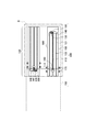
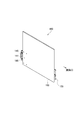
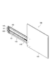
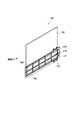
- FIG. 1 is a usage diagram of the meshing chain type door opening and closing device according to one embodiment of the present invention
- FIG. 2 is an installation state diagram of the meshing chain type door opening and closing device shown in FIG.
- FIG. 3 is a perspective view of the meshing chain type door opening / closing device with the entrance / exit opened as seen from the door side
- FIG. 4 is a perspective view of the meshing chain type door opening / closing device with the entrance / exit closed from the door portion installation side
- 5 is a perspective view of the meshing chain door opening / closing device of FIG. 3 as viewed from the meshing chain installation side
- FIG. 1 is a usage diagram of the meshing chain type door opening and closing device according to one embodiment of the present invention
- FIG. 2 is an installation state diagram of the meshing chain type door opening and closing device shown in FIG.
- FIG. 3 is a perspective view of the meshing chain type door opening / closing device with the entrance / exit opened as seen from the door side
- FIG. 4 is a perspective view
- FIG. 6 is a perspective view of the meshing chain door opening / closing device of FIG. 4 from the meshing chain installation side.
- FIG. 7 is a front view of the meshing chain door opening / closing device of FIG. 5 as viewed from the meshing chain installation side
- FIG. 8 is a meshing chain door opening / closing device of FIG.
- FIG. 9 is a front view seen from the side
- FIG. 10 is an enlarged view showing a part of the type door opening and closing device
- FIG. 10 is a side view of the meshing chain type door opening and closing device of FIG. 1 viewed from the entrance / exit
- FIG. 11 is a meshing chain type of FIG.
- FIG. 12 installs the meshing chain type door opening / closing apparatus of FIG. It is a top view of the made platform.
- a meshing chain type door opening and closing device 100 is provided on a platform H and horizontally opens a door portion 150 that opens and closes an entrance E to a vehicle T such as a train. It is driven so as to be able to advance and retreat in the direction, and is installed and used in the protective wall B that accommodates the door portion 150 while avoiding the passenger P from falling on the track.
- the meshing chain door opening / closing device 100 of the present embodiment is rigidized integrally in a state of being meshed with each other and opposed to each other, and can be separated from each other to be freely branched.
- a pair of meshing chains 110 that are driven to move forward and backward in the horizontal direction, chain guide means 120 provided with a chain storage groove 121 for guiding and storing the meshing chains branched from each other, and a pair of meshing chains 110
- a driving sprocket 130 that engages with one side to drive the pair of meshing chains 110 so as to advance and retreat, a drive source 140 that supplies driving force to the driving sprocket 130, and a pair of meshing that are installed on the platform H.
- the meshing chain door opening / closing device 100 drives a linear motion mechanism 210 such as a ball cylinder by a drive source 240 to drive the door portion 250 so that it can advance and retreat in the horizontal direction.
- the overall length of the device is shortened along the rigid direction of the pair of meshing chains 110, that is, the horizontal direction in which the door portion 150 is driven, thereby reducing the burden of installation work including the device transporting operation. It is like that. More specifically, as shown in FIG.
- the length La1 of the door portion 150 of the meshing chain door opening and closing device 100 according to the present embodiment and the length Lb1 of the door portion 250 of the door opening and closing device 200 according to the comparative example. are equal to each other, the length La2 from the end of the door portion 150 to the end of the drive source 140 is shorter than the length Lb2 from the end of the door portion 250 to the end of the drive source 240.
- 100 is reduced in size as compared with the door opening and closing apparatus 200 according to the comparative example, and reduces the burden of installation work including the transfer work of the apparatus. Further, as shown in FIGS.
- the meshing chain door opening / closing device 100 is configured so that the driving sprocket 130 is engaged with the meshing chain 110 at the bent portions of the pair of meshing chains 110.
- the overall length La is shortened to the total length of the length La1 of the door portion 150 and the diameter of the drive sprocket 130, thereby avoiding complications in apparatus installation work. .
- the meshing chain door opening / closing device 100 opens and closes the entrance / exit E by a door portion 150 that is driven to move in the horizontal direction by the meshing chain 110.
- the meshing chain type door opening / closing device 100 is configured such that the door portion 150 is fixedly connected to the distal end portions 111 of the pair of meshing chains 110.
- the overall thickness Ta is reduced to a size that combines the thickness of the pair of meshing chains 110 and the thickness of the door portion 150 so that the entire apparatus is thin, and the door portion 150 is horizontally formed by the pair of meshing chains 110.
- a device configuration that opens and closes the entrance / exit E with the door portion 150 is realized as compared with the door opening and closing device 200 having the entire thickness Tb, and at the same time, the width W1 of the entire device including the protective wall B is minimized.
- Enough space is secured on the platform H that allows the passenger P to narrow and pass safely, and the stairs ST and the platform in the platform H are secured.
- Tohomu H and narrow passage width W2 is unrolled end-to-end is adapted to achieve a safe passage, such as passengers riding in a wheelchair.
- the meshing chain type door opening and closing device 100 includes a pair of coupling pins 160 that connect and fix the pair of meshing chains 110 and the door portion 150 to each other. Since the door part 150 is attached to the tip part 111 of the pair of meshing chains 110 on the platform H by being attached to the tip part 111 of the meshing chain 110, the tip part 111 and the door part of the pair of meshing chains 110 in advance. Compared with the case where the apparatus is installed in a state where 150 is fixedly connected to each other, the pair of meshing chains 110 and the door portion 150 are fixedly connected to each other by a simple operation on the platform H, thereby further avoiding the complicated installation work. It is supposed to be.
- the meshing chain type door opening and closing apparatus 100 includes a chain guide unit 120 in the virtual plane S including the rigid direction and the branching direction of the pair of meshing chains 110.
- the pair of meshing chains 110 and the chain guiding means 120 are shifted from each other in the thickness direction by the rectangular chain guide plate having the rigid direction as the longitudinal direction. Since the thickness of the pair of meshing chains 110 and the chain guide means 120 as a whole is formed thin along the thickness direction of the apparatus, it is sufficient that the installation space can be further narrowed and passengers can pass safely in the platform H. The traffic space is further expanded.
- the meshing chain type door opening / closing device 100 includes a driving sprocket 130 formed on the chain guide means 120 and one side of the pair of meshing chains 110.
- the chain guiding means 120 and the driving sprocket 130 are mutually connected along the thickness direction. Since the increase in the thickness of the entire apparatus caused by being arranged in a state shifted to the upper limit is avoided, sufficient space for the passenger P to pass safely in the platform H by further narrowing the space of the entire apparatus. The space has been expanded further.
- the meshing chain door opening / closing device 100 is in contact with the peripheral surface of the guide roller 170 pivotally attached to the door portion 150 and extends in the rigid direction. Since the guide rail 180 having 181 is fixedly installed on the end surface of the chain guide means 120, the guide rail surface can be avoided while increasing the thickness of the apparatus even when the chain guide means 120 is formed thin. Since the contact width of 181 and the guide roller 170 is sufficiently secured, the entire apparatus including the door portion 150 is formed thin, and the entrance / exit E is smoothly opened / closed to realize safer getting on / off the vehicle T such as a train. It is supposed to be.
- the end surface of the chain guide means 120 is in contact with the peripheral surface of the guide roller 170 pivotally attached to the door portion 150 and extends in the rigid direction as a guide rail surface. You may combine.
- the mesh chain type door opening / closing device 100 avoids an increase in the number of parts as compared with the case where the guide rail 180 is separately provided and the door portion 150 is driven to move forward and backward, so that the thickness of the entire device is further increased. In addition to avoiding this, it is possible to smoothly open and close the entrance / exit E to realize safer getting on and off the vehicle T such as a train.
- the meshing chain type door opening and closing device 100 is fixedly disposed on the chain guiding means 120 in a state where the drive source 140 is shifted from the virtual plane S, as shown in FIGS. 3, 4, 10 and 11.
- the drive shaft 141 of the drive source 140 is disposed along the branching direction of the pair of meshing chains 110 and connected to the drive sprocket 130 via the orthogonal gear 190, thereby driving the drive shaft 141 of the drive source 140.
- the drive source 140 is brought closer to the chain guide means 120 along the thickness direction of the drive sprocket 130, that is, the thickness direction of the device, and the overall thickness of the device is reduced.
- the linear motion mechanism 210 such as a ball cylinder is driven by the drive source 240 to drive the door portion 250. Since the location of the length La is shorter than the length Lb of the door opening and closing device 200 according to the comparative example, which is a complication of the installation work more to further avoid.
- the meshing chain type door opening and closing device 100 of the present embodiment obtained in this way is stiffened integrally in a state of being meshed with each other and opposed to each other, and can be separated from each other so as to be able to branch and thereby advance and retract in the horizontal direction.
- a pair of meshing chains 110 that are freely driven, a chain guiding means 120 provided with a chain storage groove 121 for guiding and storing the meshing chains branched from each other, and one of the pair of meshing chains 110 are engaged.
- the driving sprocket 130 that drives the pair of meshing chains 110 to move forward and backward, the drive source 140 that supplies driving force to the driving sprocket 130, and the platform H are installed and driven by the pair of meshing chains 110.
- a door portion 150 for opening and closing the entrance E to the vehicle T, and the door portion 150 is a pair of meshing chains 1.
Landscapes
- Engineering & Computer Science (AREA)
- Transportation (AREA)
- Mechanical Engineering (AREA)
- Platform Screen Doors And Railroad Systems (AREA)
- Power-Operated Mechanisms For Wings (AREA)
Abstract
乗降客が安全に通行することができる十分な通行スペースを確保すると同時にプラットホームおよび車両間の隙間への乗降客の落下を回避するとともに電車などの車両への安全な乗り降りを実現し、設置作業の煩雑さを回避する噛合チェーン式ドア開閉装置を提供すること。 相互に噛み合って剛直化するとともに分岐自在となる一対の噛合チェーン(110)と、チェーン収納用溝(121)が設けられたチェーン案内手段(120)と、一対の噛合チェーン(110)を進退自在に駆動する駆動用スプロケット(130)と、この駆動用スプロケット(130)に駆動力を供給する駆動源と、一対の噛合チェーン(110)によって駆動されるドア部(150)とを備えた噛合チェーン式ドア開閉装置(100)。
Description
本発明は、プラットホームに設置されるとともに電車などの車両への乗降口を開閉するドア部を水平方向に進退自在に駆動するドア開閉装置であって、特に、噛合チェーンを進退動作の駆動媒体として採用した噛合チェーン式ドア開閉装置に関する。
従来、ドア開閉装置として、駅構内のプラットホームから線路への転落あるいは走行する車両への接触などの危険から乗降客を防護するもの(例えば、特許文献1参照。)、電車などの車両に設けられたスライドドアを電動で開閉するもの(例えば、特許文献2。)、および乗降客が線路に落下することを防止する足場を提供するもの(例えば、特許文献3参照。)がある。
また、引き戸などのドアを開閉する駆動装置として、ボール螺子を備えてドアを進退自在に駆動するボールシリンダが用いられる場合もある。
また、引き戸などのドアを開閉する駆動装置として、ボール螺子を備えてドアを進退自在に駆動するボールシリンダが用いられる場合もある。
しかしながら、特許文献1に開示された腰高式プラットホームドア装置では、駆動装置からドアへ駆動力を伝達する回動伝達手段などの伝達機構の構造が複雑であるとともにその部品点数を低減することが困難であるため、装置をその厚み方向に沿って薄く形成してプラットホームにおける装置設置スペースを狭め、乗降客が安全に通行することができる十分な通行スペースをプラットホーム内に確保することが困難であるという問題点があった。
たとえば、プラットホーム内の階段と電車などの車両に臨むプラットホーム終端との間の通路幅はプラットホーム内の他の領域と比べて狭くなるため、一定の車幅を有する車椅子に乗った乗降客が、ラッシュアワーなどの混雑時においてプラットホーム内の階段とプラットホーム終端との間の通路を通行しようとするとその通行が困難になる場合があるという問題点があった。
たとえば、プラットホーム内の階段と電車などの車両に臨むプラットホーム終端との間の通路幅はプラットホーム内の他の領域と比べて狭くなるため、一定の車幅を有する車椅子に乗った乗降客が、ラッシュアワーなどの混雑時においてプラットホーム内の階段とプラットホーム終端との間の通路を通行しようとするとその通行が困難になる場合があるという問題点があった。
また、特許文献2に開示された電動スライドドア装置では、電動スライドドア装置自体が電車に設けられているため、プラットホームおよび電車間に形成される隙間へ乗降客が落下することを根本的に回避することができないという問題点があった。
また、特許文献3に開示された鉄道車両用の安全足場装置では、鉄道車両自体に設けられた乗降口への乗客の侵入を防止できないため、足場とプラットホームの段差、あるいは足場と鉄道車両の床面との間の段差の発生を完全に回避して鉄道車両への安全な乗り降りを実現することが困難であるとともにプラットホーム内部に装置を設置する工事が必要となって設置作業の煩雑さを回避することが困難になるという問題点があった。
また、特許文献3に開示された鉄道車両用の安全足場装置では、鉄道車両自体に設けられた乗降口への乗客の侵入を防止できないため、足場とプラットホームの段差、あるいは足場と鉄道車両の床面との間の段差の発生を完全に回避して鉄道車両への安全な乗り降りを実現することが困難であるとともにプラットホーム内部に装置を設置する工事が必要となって設置作業の煩雑さを回避することが困難になるという問題点があった。
また、ボールシリンダなどの直動機構を介してその長手方向にドアを開閉する場合、乗降口を開いた状態における装置全体の長さが、ドア部の幅すなわち直動機構のストロークと直動機構の端に接続されたモータなどの駆動源の長さとを合わせた長さ以上になるため、水平方向に沿った装置全体の長さを短くして設置作業の負担を軽減することが困難であるという問題点があった。
そこで、本発明が解決しようとする技術的課題、すなわち、本発明の目的は、乗降客が安全に通行することができる十分な通行スペースをプラットホーム内に確保すると同時にプラットホームおよび車両間の隙間への乗降客の落下を回避するとともに電車などの車両への安全な乗り降りを実現し、設置作業の煩雑さを回避する噛合チェーン式ドア開閉装置を提供することである。
請求項1に係る本発明は、相互に噛み合って対向配置した状態で一体に剛直化するとともに相互に噛み外れて分岐自在となることで水平方向に進退自在に駆動される一対の噛合チェーンと、相互に分岐した噛合チェーンを案内して収納するチェーン収納用溝が設けられたチェーン案内手段と、前記一対の噛合チェーンの一方に係合して一対の噛合チェーンを進退自在に駆動する駆動用スプロケットと、該駆動用スプロケットに駆動力を供給する駆動源と、プラットホームに設置されているとともに前記一対の噛合チェーンによって駆動されて車両への乗降口を開閉するドア部とを備えた噛合チェーン式ドア開閉装置であって、前記ドア部が、前記一対の噛合チェーンの先端部に固定接続されていることにより、前述した課題を解決したものである。
請求項2に係る本発明は、請求項1に記載の構成に加えて、前記ドア部および一対の噛合チェーンを相互に固定接続する連結ピンが、前記一対の噛合チェーンの先端部に付設されていることにより、前述した課題を解決したものである。
請求項3に係る本発明は、請求項1または請求項2に記載の構成に加えて、前記チェーン案内手段が、前記一対の噛合チェーンの剛直方向および分岐方向を含む仮想平面内に設けられているとともに前記剛直方向を長手方向とする矩形状のチェーン案内プレートであることにより、前述した課題を解決したものである。
請求項4に係る本発明は、請求項3に記載の構成に加えて、前記駆動用スプロケットが、前記チェーン案内プレートに形成されて前記一対の噛合チェーンの一方の側方に開口する凹状の駆動用スプロケット収容溝に収容された状態で前記仮想平面内にチェーン案内プレートとともに設けられていることにより、前述した課題を解決したものである。
請求項5に係る本発明は、請求項3または請求項4に記載の構成に加えて、前記ドア部に軸着されたガイドローラの周面に接するとともに前記剛直方向に延びるガイドレール面を有するガイドレールが、前記チェーン案内プレートの端面に固定設置されていることにより、前述した課題を解決したものである。
請求項6に係る本発明は、請求項3または請求項4に記載の構成に加えて、前記チェーン案内プレートが、前記ドア部に軸着されたガイドローラの周面に接するとともに前記剛直方向に延びてガイドレール面となる端面を有していることにより、前述した課題を解決したものである。
請求項7に係る本発明は、請求項3ないし請求項6のいずれか一つに記載の構成に加えて、前記駆動源が、前記仮想平面からずらした状態で前記チェーン案内プレートに固定配置され、前記駆動源の駆動軸が、前記一対の噛合チェーンの分岐方向に沿って配置されているとともに直交ギアを介して駆動用スプロケットに接続されていることにより、前述した課題を解決したものである。
請求項1に係る本発明の噛合チェーン式ドア開閉装置によれば、相互に噛み合って対向配置した状態で一体に剛直化するとともに相互に噛み外れて分岐自在となることで水平方向に進退自在に駆動される一対の噛合チェーンと、相互に分岐した噛合チェーンを案内して収納するチェーン収納用溝が設けられたチェーン案内手段と、一対の噛合チェーンの一方に係合して一対の噛合チェーンを進退自在に駆動する駆動用スプロケットと、この駆動用スプロケットに駆動力を供給する駆動源と、プラットホームに設置されているとともに一対の噛合チェーンによって駆動されて車両への乗降口を開閉するドア部とを備えたことによって、ボールシリンダなどの直動機構を配置してドア部を駆動する場合に比べて一対の噛合チェーンの剛直方向すなわちドア部が駆動される水平方向に沿って装置全体の長さを短くして装置の搬送作業を含む装置設置作業の負担を軽減すると同時に乗降口をドア部で閉じることで乗降口への乗降客の不用意な侵入を回避してプラットホームおよび車両間の隙間への乗降客の落下を回避するとともに電車などの車両への安全な乗り降りを実現することができるばかりでなく、以下のような特有の効果を奏することができる。
すなわち、本請求項1に係る噛合チェーン式ドア開閉装置によれば、ドア部が一対の噛合チェーンの先端部に固定接続されていることにより、装置全体の厚みを最小で一対の噛合チェーンの厚みとドア部の厚みとを合わせたサイズまで近づけて装置全体が薄く形成された構造でドア部が一対の噛合チェーンで水平方向に駆動されるため、ドア部による乗降口の開閉を行う装置構成を実現すると同時にプラットホーム内における装置の設置スペースを最小限まで狭めて乗降客が安全に通行することができる十分な通行スペースをプラットホームに確保するとともにプラットホーム内の階段およびプラットホーム終端間の狭い通路幅を広げて一般の乗降客および車椅子に乗った乗降客などの安全な通行を実現し、設置作業の煩雑さを回避することができる。
すなわち、本請求項1に係る噛合チェーン式ドア開閉装置によれば、ドア部が一対の噛合チェーンの先端部に固定接続されていることにより、装置全体の厚みを最小で一対の噛合チェーンの厚みとドア部の厚みとを合わせたサイズまで近づけて装置全体が薄く形成された構造でドア部が一対の噛合チェーンで水平方向に駆動されるため、ドア部による乗降口の開閉を行う装置構成を実現すると同時にプラットホーム内における装置の設置スペースを最小限まで狭めて乗降客が安全に通行することができる十分な通行スペースをプラットホームに確保するとともにプラットホーム内の階段およびプラットホーム終端間の狭い通路幅を広げて一般の乗降客および車椅子に乗った乗降客などの安全な通行を実現し、設置作業の煩雑さを回避することができる。
そして、本請求項2に係る噛合チェーン式ドア開閉装置によれば、請求項1に記載の噛合チェーン式ドア開閉装置が奏する効果に加えて、ドア部および一対の噛合チェーンを相互に固定接続する連結ピンが一対の噛合チェーンの先端部に付設されていることにより、一対の噛合チェーンと相互に分離された状態で搬送されたドア部がプラットホーム上で一対の噛合チェーンの先端部に取り付けられるため、予めドア部および一対の噛合チェーンの先端部を相互に固定接続した状態で装置を設置する場合に比べて、プラットホーム上において簡便な作業でドア部および一対の噛合チェーンを相互に固定接続して設置作業の煩雑さを回避することができる。
そして、本請求項3に係る噛合チェーン式ドア開閉装置によれば、請求項1または請求項2に記載の噛合チェーン式ドア開閉装置が奏する効果に加えて、チェーン案内手段が、一対の噛合チェーンの剛直方向および分岐方向を含む仮想平面内に設けられているとともに剛直方向を長手方向とする矩形状のチェーン案内プレートであることにより、一対の噛合チェーンおよびチェーン案内プレートを厚み方向に相互にずらして配置した場合に比べて装置の厚み方向に沿って装置全体が薄く形成されるため、設置スペースを狭めてプラットホーム内で乗降客が安全に通行することができる十分な通行スペースをより一層広げることができる。
そして、本請求項4に係る噛合チェーン式ドア開閉装置によれば、請求項3に記載の噛合チェーン式ドア開閉装置が奏する効果に加えて、駆動用スプロケットがチェーン案内プレートに形成されて一対の噛合チェーンの一方の側方に開口する凹状の駆動用スプロケット収容溝に収容された状態で仮想平面内にチェーン案内プレートとともに設けられていることにより、チェーン案内プレートおよび駆動用スプロケットが厚み方向に沿って相互にずれた状態で配置される場合に比べて装置全体の厚みがより一層小さくなるため、装置全体の設置スペース増大を回避してプラットホーム内で乗降客が安全に通行することができる十分な通行スペースをさらに広げることができる。
そして、本請求項5に係る噛合チェーン式ドア開閉装置によれば、請求項3または請求項4に記載の噛合チェーン式ドア開閉装置が奏する効果に加えて、ドア部に軸着されたガイドローラの周面に接するとともに剛直方向に延びるガイドレール面を有するガイドレールがチェーン案内プレートの端面に固定設置されていることにより、チェーン案内プレートを薄く形成した場合であっても装置の厚みが増大することを回避しつつガイドレール面およびガイドローラの接触幅が十分に確保されるため、ドア部の装置の薄く形成するとともに乗降口を円滑に開閉して電車などの車両へのさらに安全な乗り降りを実現することができる。
そして、本請求項6に係る噛合チェーン式ドア開閉装置によれば、請求項3または請求項4に記載の噛合チェーン式ドア開閉装置が奏する効果に加えて、チェーン案内プレートがドア部に軸着されたガイドローラの周面に接するとともに剛直方向に延びてガイドレール面となる端面を有していることにより、別途ガイドレールを設けてドア部を進退自在に駆動する場合に比べて部品点数の増大が回避されるため、装置全体の厚みの増大を一層回避するとともに乗降口を円滑に開閉して電車などの車両へのより一層安全な乗り降りを実現することができる。
そして、本請求項7に係る噛合チェーン式ドア開閉装置によれば、請求項1ないし請求項6のいずれか一つに記載の噛合チェーン式ドア開閉装置が奏する効果に加えて、駆動源が仮想平面からずらした状態でチェーン案内プレートに固定配置され、駆動源の駆動軸が一対の噛合チェーンの分岐方向に沿って配置されているとともに直交ギアを介して駆動用スプロケットに接続されていることにより、駆動源の駆動軸が駆動用スプロケットに交差している場合に比べて駆動用スプロケットの厚み方向すなわち装置の厚み方向に沿って駆動源をチェーン案内プレートに近づけて装置全体の厚みが薄く形成されるとともに直動機構を用いてドア部を駆動する場合に比べて装置の長さが短くなるため、設置作業の煩雑さをより一層回避することができる。
本発明の噛合チェーン式ドア開閉装置は、相互に噛み合って対向配置した状態で一体に剛直化するとともに相互に噛み外れて分岐自在となることで水平方向に進退自在に駆動される一対の噛合チェーンと、相互に分岐した噛合チェーンを案内して収納するチェーン収納用溝が設けられたチェーン案内手段と一対の噛合チェーンの一方に係合して一対の噛合チェーンを進退自在に駆動する駆動用スプロケットとこの駆動用スプロケットに駆動力を供給する駆動源とプラットホームに設置されているとともに一対の噛合チェーンによって駆動されて車両への乗降口を開閉するドア部とを備え、ドア部が一対の噛合チェーンの先端部に固定接続され、乗降客が安全に通行することができる十分な通行スペースをプラットホーム内に確保すると同時にプラットホームおよび車両間の隙間への乗降客の落下を回避するとともに電車などの車両への安全な乗り降りを実現し、設置作業の煩雑さを回避することができるものであれば、その具体的な実施の態様は、如何なるものであっても何ら構わない。
また、本発明の噛合チェーン式ドア開閉装置で用いられる一対の噛合チェーンは、例えば、チェーン幅方向に1列の単列であるもの、チェーン幅方向に2列以上の複列であるものなど何れであっても構わないが、チェーン幅方向に2列以上の複列であるものを採用する場合には、一対の噛合チェーンの一方を構成するフック状外歯プレートとフック状内歯プレートが、これに対向する他方の噛合チェーンを構成するフック状外歯プレートとフック状内歯プレートに対してチェーン幅方向の複列に亙ってそれぞれフック状に多重かつ強固に噛み合うため、噛合チェーンのチェーン幅方向に生じがちな座屈を確実に抑制して優れたチェーン耐久性を実現することができるので、より好ましい。
また、本発明の噛合チェーン式ドア開閉装置で用いられる一対の噛合チェーンは、ガイドローラを有していないもの、すなわち、ブシュのみを有するもの、ガイドローラを有するものなど何れであっても構わないが、ブシュのみを有するものを採用する場合には、チェーン部品点数が低減して、チェーン重量の軽量化を図ることができる。
また、本発明の噛合チェーン式ドア開閉装置をプラットホーム上に乗降口に対して各一つ配置して片側から乗降口を開閉してもよいし、本発明の噛合チェーン式ドア開閉装置をプラットホーム上の乗降口に対してその両側に各一つ設置して一つの乗降口をその両側から開閉してもよい。
また、本発明の噛合チェーン式ドア開閉装置は、プラットホーム内の落下防止用の防護壁内に収容されるように取り付けられてもよいし、プラットホーム側から噛合チェーンなどを点検することができるように落下防止柵に取り付けられてもよい。
また、本発明の噛合チェーン式ドア開閉装置は、プラットホーム内の落下防止用の防護壁内に収容されるように取り付けられてもよいし、プラットホーム側から噛合チェーンなどを点検することができるように落下防止柵に取り付けられてもよい。
以下、本発明の一実施例である噛合チェーン式ドア開閉装置100を図面に基づいて説明する。
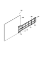
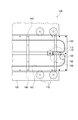
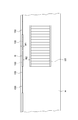
ここで、図1は、本発明の一実施例である噛合チェーン式ドア開閉装置の使用態様図であり、図2は、図1に示した噛合チェーン式ドア開閉装置の設置状態図であり、図3は、乗降口を開いた噛合チェーン式ドア開閉装置をドア部側から見た斜視図であり、図4は、乗降口を閉じた噛合チェーン式ドア開閉装置をドア部設置側から見た斜視図であり、図5は、図3の噛合チェーン式ドア開閉装置を噛合チェーン設置側から見た斜視図であり、図6は、図4の噛合チェーン式ドア開閉装置を噛合チェーン設置側から見た斜視図であり、図7は、図5の噛合チェーン式ドア開閉装置を噛合チェーン設置側から見た正面図であり、図8は、図6の噛合チェーン式ドア開閉装置を噛合チェーン設置側から見た正面図であり、図9は、図7の噛合チェーン式ドア開閉装置の一部を示した拡大図であり、図10は、図1の噛合チェーン式ドア開閉装置を乗降口側から見た側面図であり、図11は、図1の噛合チェーン式ドア開閉装置を上側から見た平面図(a)と、比較例に係るドア開閉装置を上側から見た平面図(b)であり、図12は、図1の噛合チェーン式ドア開閉装置が設置されたプラットホームの平面図である。
ここで、図1は、本発明の一実施例である噛合チェーン式ドア開閉装置の使用態様図であり、図2は、図1に示した噛合チェーン式ドア開閉装置の設置状態図であり、図3は、乗降口を開いた噛合チェーン式ドア開閉装置をドア部側から見た斜視図であり、図4は、乗降口を閉じた噛合チェーン式ドア開閉装置をドア部設置側から見た斜視図であり、図5は、図3の噛合チェーン式ドア開閉装置を噛合チェーン設置側から見た斜視図であり、図6は、図4の噛合チェーン式ドア開閉装置を噛合チェーン設置側から見た斜視図であり、図7は、図5の噛合チェーン式ドア開閉装置を噛合チェーン設置側から見た正面図であり、図8は、図6の噛合チェーン式ドア開閉装置を噛合チェーン設置側から見た正面図であり、図9は、図7の噛合チェーン式ドア開閉装置の一部を示した拡大図であり、図10は、図1の噛合チェーン式ドア開閉装置を乗降口側から見た側面図であり、図11は、図1の噛合チェーン式ドア開閉装置を上側から見た平面図(a)と、比較例に係るドア開閉装置を上側から見た平面図(b)であり、図12は、図1の噛合チェーン式ドア開閉装置が設置されたプラットホームの平面図である。
図1に示すように、本発明の一実施例である噛合チェーン式ドア開閉装置100は、プラットホームHに設けられているとともに電車などの車両Tへの乗降口Eを開閉するドア部150を水平方向に進退自在に駆動するものであり、乗降客Pが線路に転落することを回避するとともにドア部150を収納する防護壁B内に設置されて使用される。
そして、本実施例の噛合チェーン式ドア開閉装置100は、図1乃至図12に示すように、相互に噛み合って対向配置した状態で一体に剛直化するとともに相互に噛み外れて分岐自在となることで水平方向に進退自在に駆動される一対の噛合チェーン110と、相互に分岐した噛合チェーンを案内して収納するチェーン収納用溝121が設けられたチェーン案内手段120と、一対の噛合チェーン110の一方に係合して一対の噛合チェーン110を進退自在に駆動する駆動用スプロケット130と、この駆動用スプロケット130に駆動力を供給する駆動源140と、プラットホームHに設置されているとともに一対の噛合チェーン110によって駆動されて車両Tへの乗降口Eを開閉するドア部150とを備えている。
これにより、噛合チェーン式ドア開閉装置100は、図1および図11に示すように、ボールシリンダなどの直動機構210を駆動源240で駆動してドア部250を水平方向に進退自在に駆動するドア開閉装置200に比べて一対の噛合チェーン110の剛直方向すなわちドア部150が駆動される水平方向に沿って装置全体の長さを短くして装置の搬送作業を含む設置作業の負担を軽減するようになっている。
より具体的には、図11に示すように、本実施例に係る噛合チェーン式ドア開閉装置100のドア部150の長さLa1と比較例に係るドア開閉装置200のドア部250の長さLb1が相互に等しい場合、ドア部250の終端から駆動源240の端までの長さLb2よりドア部150の終端から駆動源140の端までの長さLa2が短くなるため、噛合チェーン式ドア開閉装置100は、比較例に係るドア開閉装置200に比べて小型化されて装置の搬送作業を含む設置作業の負担を軽減するようになっている。
また、本実施例に係る噛合チェーン式ドア開閉装置100は、図9および図11に示すように、駆動用スプロケット130が一対の噛合チェーン110の屈曲部で噛合チェーン110に係合するため、装置全体の長さLaをドア部150の長さLa1と駆動用スプロケット130の直径のサイズとを合わせた長さまで短くなるように形成して装置の設置作業における煩雑さを回避するようになっている。
加えて、近年の電車では電車自体に設けられる乗降口の設置数が増え、それに対応してプラットホーム上に設けられる乗降口の設置数が多くなり、しかも電車の停止精度および乗降の際の利便性向上の問題から電車自体に設けられる乗降口に比べてプラットホーム上に設けられる乗降口の幅を広く設計する必要が生じるが、図2に示すように、噛合チェーン式ドア開閉装置100によれば、上下に配置された2つの噛合チェーン式ドア開閉装置100のそれぞれの全長がドア部150の全長に略等しいため、プラットホーム上における噛合チェーン式ドア開閉装置100の設置スペースの増大を回避してプラットホーム上における乗降口の設置スペースを確保することができる。
また、本実施例に係る噛合チェーン式ドア開閉装置100は、図1乃至図8に示すように、噛合チェーン110によって水平方向に進退自在に駆動されるドア部150により乗降口Eを開閉することで乗降口Eへの乗降客Pの不用意な侵入を回避してプラットホームHおよび車両T間の隙間への乗降客Pの落下を回避するとともに電車などの車両Tへの安全な乗り降りを実現するようになっている。
さらに、噛合チェーン式ドア開閉装置100は、図2乃至図8、図11、図12に示すように、ドア部150が一対の噛合チェーン110の先端部111に固定接続されていることにより、装置全体の厚みTaを最小で一対の噛合チェーン110の厚みとドア部150の厚みとを合わせたサイズまで狭めて装置全体が薄く形成された構造でドア部150が一対の噛合チェーン110で水平方向に駆動されるため、装置全体の厚みTbを有するドア開閉装置200に比べてドア部150による乗降口Eの開閉を行う装置構成を実現すると同時に防護壁Bを含む装置全体の幅W1を最小限まで狭めて乗降客Pが安全に通行することができる十分な通行スペースをプラットホームH上に確保するとともに、プラットホームH内の階段STおよびプラットホームH終端間の狭い通路幅W2が広げられて車椅子に乗った乗降客などの安全な通行を実現するようになっている。
これにより、噛合チェーン式ドア開閉装置100は、図1および図11に示すように、ボールシリンダなどの直動機構210を駆動源240で駆動してドア部250を水平方向に進退自在に駆動するドア開閉装置200に比べて一対の噛合チェーン110の剛直方向すなわちドア部150が駆動される水平方向に沿って装置全体の長さを短くして装置の搬送作業を含む設置作業の負担を軽減するようになっている。
より具体的には、図11に示すように、本実施例に係る噛合チェーン式ドア開閉装置100のドア部150の長さLa1と比較例に係るドア開閉装置200のドア部250の長さLb1が相互に等しい場合、ドア部250の終端から駆動源240の端までの長さLb2よりドア部150の終端から駆動源140の端までの長さLa2が短くなるため、噛合チェーン式ドア開閉装置100は、比較例に係るドア開閉装置200に比べて小型化されて装置の搬送作業を含む設置作業の負担を軽減するようになっている。
また、本実施例に係る噛合チェーン式ドア開閉装置100は、図9および図11に示すように、駆動用スプロケット130が一対の噛合チェーン110の屈曲部で噛合チェーン110に係合するため、装置全体の長さLaをドア部150の長さLa1と駆動用スプロケット130の直径のサイズとを合わせた長さまで短くなるように形成して装置の設置作業における煩雑さを回避するようになっている。
加えて、近年の電車では電車自体に設けられる乗降口の設置数が増え、それに対応してプラットホーム上に設けられる乗降口の設置数が多くなり、しかも電車の停止精度および乗降の際の利便性向上の問題から電車自体に設けられる乗降口に比べてプラットホーム上に設けられる乗降口の幅を広く設計する必要が生じるが、図2に示すように、噛合チェーン式ドア開閉装置100によれば、上下に配置された2つの噛合チェーン式ドア開閉装置100のそれぞれの全長がドア部150の全長に略等しいため、プラットホーム上における噛合チェーン式ドア開閉装置100の設置スペースの増大を回避してプラットホーム上における乗降口の設置スペースを確保することができる。
また、本実施例に係る噛合チェーン式ドア開閉装置100は、図1乃至図8に示すように、噛合チェーン110によって水平方向に進退自在に駆動されるドア部150により乗降口Eを開閉することで乗降口Eへの乗降客Pの不用意な侵入を回避してプラットホームHおよび車両T間の隙間への乗降客Pの落下を回避するとともに電車などの車両Tへの安全な乗り降りを実現するようになっている。
さらに、噛合チェーン式ドア開閉装置100は、図2乃至図8、図11、図12に示すように、ドア部150が一対の噛合チェーン110の先端部111に固定接続されていることにより、装置全体の厚みTaを最小で一対の噛合チェーン110の厚みとドア部150の厚みとを合わせたサイズまで狭めて装置全体が薄く形成された構造でドア部150が一対の噛合チェーン110で水平方向に駆動されるため、装置全体の厚みTbを有するドア開閉装置200に比べてドア部150による乗降口Eの開閉を行う装置構成を実現すると同時に防護壁Bを含む装置全体の幅W1を最小限まで狭めて乗降客Pが安全に通行することができる十分な通行スペースをプラットホームH上に確保するとともに、プラットホームH内の階段STおよびプラットホームH終端間の狭い通路幅W2が広げられて車椅子に乗った乗降客などの安全な通行を実現するようになっている。
さらに、本実施例に係る噛合チェーン式ドア開閉装置100は、図1、図9および図10に示すように、一対の噛合チェーン110およびドア部150を相互に固定接続する連結ピン160が一対の噛合チェーン110の先端部111に付設されていることにより、ドア部150がプラットホームH上で一対の噛合チェーン110の先端部111に取り付けられるため、予め一対の噛合チェーン110の先端部111およびドア部150を相互に固定接続した状態で装置を設置する場合に比べて、プラットホームH上で簡便な作業で一対の噛合チェーン110およびドア部150を相互に固定接続して設置作業の煩雑さを一層回避するようになっている。
本実施例に係る噛合チェーン式ドア開閉装置100は、図7乃至図9および図10に示すように、チェーン案内手段120が、一対の噛合チェーン110の剛直方向および分岐方向を含む仮想平面S内に設けられているとともに剛直方向を長手方向とする矩形状のチェーン案内プレートであることにより、一対の噛合チェーン110およびチェーン案内手段120をそれらの厚み方向に相互にずらして配置した場合に比べて装置の厚み方向に沿って一対の噛合チェーン110およびチェーン案内手段120全体の厚みが薄く形成されるため、設置スペースをより一層狭めてプラットホームH内で乗降客が安全に通行することができる十分な通行スペースをより一層広げるようになっている。
さらに、本実施例に係る噛合チェーン式ドア開閉装置100は、図9乃至図11に示すように、駆動用スプロケット130が、チェーン案内手段120に形成されて一対の噛合チェーン110の一方の側方に開口する凹状の駆動用スプロケット収容溝122に収容された状態で仮想平面S内にチェーン案内手段120とともに設けられていることにより、チェーン案内手段120および駆動用スプロケット130が厚み方向に沿って相互にずれた状態で配置されることで生じる装置全体の厚みの増大が回避されるため、装置全体のスペースをより一層狭めてプラットホームH内で乗降客Pが安全に通行することができる十分な通行スペースをさらに広げるようになっている。
そして、本実施例に係る噛合チェーン式ドア開閉装置100は、図7乃至図10に示すように、ドア部150に軸着されたガイドローラ170の周面に接するとともに剛直方向に延びるガイドレール面181を有するガイドレール180が、チェーン案内手段120の端面に固定設置されていることにより、チェーン案内手段120を薄く形成した場合であっても装置の厚みが増大することを回避しつつガイドレール面181およびガイドローラ170の接触幅が十分に確保されるため、ドア部150を含む装置全体を薄く形成するとともに乗降口Eを円滑に開閉して電車などの車両Tへのさらに安全な乗り降りを実現するようになっている。
また、本実施例に係る噛合チェーン式ドア開閉装置100では、チェーン案内手段120の端面が、ドア部150に軸着されたガイドローラ170の周面に接するとともに剛直方向に延びてガイドレール面として兼用されてもよい。
この場合、噛合チェーン式ドア開閉装置100は、別途ガイドレール180を設けてドア部150を進退自在に駆動する場合に比べて部品点数の増大が回避されるため、装置全体の厚みの増大を一層回避するとともに乗降口Eを円滑に開閉して電車などの車両Tへのより一層安全な乗り降りを実現するようになっている。
この場合、噛合チェーン式ドア開閉装置100は、別途ガイドレール180を設けてドア部150を進退自在に駆動する場合に比べて部品点数の増大が回避されるため、装置全体の厚みの増大を一層回避するとともに乗降口Eを円滑に開閉して電車などの車両Tへのより一層安全な乗り降りを実現するようになっている。
本実施例に係る噛合チェーン式ドア開閉装置100は、図3、図4、図10および図11に示すように、駆動源140が仮想平面Sからずらした状態でチェーン案内手段120に固定配置され、駆動源140の駆動軸141が一対の噛合チェーン110の分岐方向に沿って配置されているとともに直交ギア190を介して駆動用スプロケット130に接続されていることにより、駆動源140の駆動軸141が駆動用スプロケット130に交差している場合に比べて駆動用スプロケット130の厚み方向すなわち装置の厚み方向に沿って駆動源140をチェーン案内手段120に近づけて装置全体の厚みが薄く形成されるとともにボールシリンダなどの直動機構210を駆動源240によって駆動してドア部250を駆動する場合に比べて装置の長さLaが比較例に係るドア開閉装置200の長さLbより短くなるため、設置作業の煩雑さをより一層回避するようになっている。
このようにして得られた本実施例の噛合チェーン式ドア開閉装置100は、相互に噛み合って対向配置した状態で一体に剛直化するとともに相互に噛み外れて分岐自在となることで水平方向に進退自在に駆動される一対の噛合チェーン110と、相互に分岐した噛合チェーンを案内して収納するチェーン収納用溝121が設けられたチェーン案内手段120と、一対の噛合チェーン110の一方に係合して一対の噛合チェーン110を進退自在に駆動する駆動用スプロケット130と、この駆動用スプロケット130に駆動力を供給する駆動源140と、プラットホームHに設置されているとともに一対の噛合チェーン110によって駆動されて車両Tへの乗降口Eを開閉するドア部150とを備え、ドア部150が一対の噛合チェーン110の先端部111に固定接続されていることにより、装置全体の厚みを最小で一対の噛合チェーン110の厚みとドア部150の厚みとを合わせたサイズまで狭めて装置全体が薄く形成された構造でドア部150が一対の噛合チェーン110で水平方向に駆動されるため、ドア部150による乗降口Eの開閉する装置構成を実すると同時にプラットホームH内における装置の設置スペースを最小限まで狭めて乗降客Pが安全に通行することができる十分な通行スペースを確保するとともに、プラットホームH内の階段およびプラットホームH終端間の狭い通路幅が広げられて車椅子に乗った乗降客などの安全な通行を実現し、予め一対の噛合チェーン110の先端部111およびドア部150を相互に固定接続した状態で装置を設置する場合に比べて、プラットホームH上で簡便な作業で一対の噛合チェーン110およびドア部150を相互に固定接続して設置作業の煩雑さを一層回避することができるなど、その効果は甚大である。
100 ・・・ 噛合チェーン式ドア開閉装置
110 ・・・ 一対の噛合チェーン
111 ・・・ 噛合チェーンの先端部
120 ・・・ チェーン案内手段
121 ・・・ チェーン収納用溝
122 ・・・駆動用スプロケット収容溝
130 ・・・ 駆動用スプロケット
140、240 ・・・ 駆動源
141 ・・・駆動源の駆動軸
150、250 ・・・ ドア部
160 ・・・ 連結ピン
170 ・・・ ガイドローラ
180 ・・・ ガイドレール面を有するガイドレール
181 ・・・ ガイドレール面
190 ・・・直交ギア
200 ・・・ドア開閉装置
210 ・・・直動機構
B ・・・ 防護壁
E ・・・ 乗降口
H ・・・プラットホーム
La、Lb ・・・ 装置長さ
La1、Lb1 ・・・ ドア部の長さ
La2、Lb2 ・・・ ドア部の終端から駆動源の端までの長さ
P ・・・乗降客
S ・・・仮想面
T ・・・車両
ST ・・・階段
Ta、Tb・・・ 装置厚み
W1 ・・・ 防護壁の幅
W2 ・・・ 防護壁から階段までの通路幅
110 ・・・ 一対の噛合チェーン
111 ・・・ 噛合チェーンの先端部
120 ・・・ チェーン案内手段
121 ・・・ チェーン収納用溝
122 ・・・駆動用スプロケット収容溝
130 ・・・ 駆動用スプロケット
140、240 ・・・ 駆動源
141 ・・・駆動源の駆動軸
150、250 ・・・ ドア部
160 ・・・ 連結ピン
170 ・・・ ガイドローラ
180 ・・・ ガイドレール面を有するガイドレール
181 ・・・ ガイドレール面
190 ・・・直交ギア
200 ・・・ドア開閉装置
210 ・・・直動機構
B ・・・ 防護壁
E ・・・ 乗降口
H ・・・プラットホーム
La、Lb ・・・ 装置長さ
La1、Lb1 ・・・ ドア部の長さ
La2、Lb2 ・・・ ドア部の終端から駆動源の端までの長さ
P ・・・乗降客
S ・・・仮想面
T ・・・車両
ST ・・・階段
Ta、Tb・・・ 装置厚み
W1 ・・・ 防護壁の幅
W2 ・・・ 防護壁から階段までの通路幅
Claims (7)
- 相互に噛み合って対向配置した状態で一体に剛直化するとともに相互に噛み外れて分岐自在となることで水平方向に進退自在に駆動される一対の噛合チェーンと、相互に分岐した噛合チェーンを案内して収納するチェーン収納用溝が設けられたチェーン案内手段と、前記一対の噛合チェーンの一方に係合して一対の噛合チェーンを進退自在に駆動する駆動用スプロケットと、該駆動用スプロケットに駆動力を供給する駆動源と、プラットホームに設置されているとともに前記一対の噛合チェーンによって駆動されて車両への乗降口を開閉するドア部とを備えた噛合チェーン式ドア開閉装置であって、
前記ドア部が、前記一対の噛合チェーンの先端部に固定接続されていることを特徴とする噛合チェーン式ドア開閉装置。 - 前記ドア部および一対の噛合チェーンを相互に固定接続する連結ピンが、前記一対の噛合チェーンの先端部に付設されていることを特徴とする請求項1に記載の噛合チェーン式ドア開閉装置。
- 前記チェーン案内手段が、前記一対の噛合チェーンの剛直方向および分岐方向を含む仮想平面内に設けられているとともに前記剛直方向を長手方向とする矩形状のチェーン案内プレートであることを特徴とする請求項1または請求項2に記載の噛合チェーン式ドア開閉装置。
- 前記駆動用スプロケットが、前記チェーン案内プレートに形成されて前記一対の噛合チェーンの一方の側方に開口する凹状の駆動用スプロケット収容溝に収容された状態で前記仮想平面内にチェーン案内プレートとともに設けられていることを特徴とする請求項3に記載の噛合チェーン式ドア開閉装置。
- 前記ドア部に軸着されたガイドローラの周面に接するとともに前記剛直方向に延びるガイドレール面を有するガイドレールが、前記チェーン案内プレートの端面に固定設置されていることを特徴とする請求項3または請求項4に記載の噛合チェーン式ドア開閉装置。
- 前記チェーン案内プレートが、前記ドア部に軸着されたガイドローラの周面に接するとともに前記剛直方向に延びてガイドレール面となる端面を有していることを特徴とする請求項3または請求項4に記載の噛合チェーン式ドア開閉装置。
- 前記駆動源が、前記仮想平面からずらした状態で前記チェーン案内プレートに固定配置され、
前記駆動源の駆動軸が、前記一対の噛合チェーンの分岐方向に沿って配置されているとともに直交ギアを介して駆動用スプロケットに接続されていることを特徴とする請求項3ないし請求項6のいずれか一つに記載の噛合チェーン式ドア開閉装置。
Applications Claiming Priority (2)
| Application Number | Priority Date | Filing Date | Title |
|---|---|---|---|
| JP2010124152A JP5259649B2 (ja) | 2010-05-31 | 2010-05-31 | 噛合チェーン式ドア開閉装置 |
| JP2010-124152 | 2010-05-31 |
Publications (1)
| Publication Number | Publication Date |
|---|---|
| WO2011152278A1 true WO2011152278A1 (ja) | 2011-12-08 |
Family
ID=45066653
Family Applications (1)
| Application Number | Title | Priority Date | Filing Date |
|---|---|---|---|
| PCT/JP2011/062105 Ceased WO2011152278A1 (ja) | 2010-05-31 | 2011-05-26 | 噛合チェーン式ドア開閉装置 |
Country Status (2)
| Country | Link |
|---|---|
| JP (1) | JP5259649B2 (ja) |
| WO (1) | WO2011152278A1 (ja) |
Cited By (3)
| Publication number | Priority date | Publication date | Assignee | Title |
|---|---|---|---|---|
| FR3002780A1 (fr) * | 2013-03-04 | 2014-09-05 | Faiveley Transp Tours | Module de porte-paliere, son montage, ensemble le comprenant, et procede de realisation d'une barriere. |
| US20180216394A1 (en) * | 2015-07-31 | 2018-08-02 | Faiveley Transport Tours | System for Guiding and Supporting a Leaf of a Platform-Access Door |
| WO2022084482A1 (en) | 2020-10-22 | 2022-04-28 | Dsm Ip Assets B.V. | Microorganisms for diterpene production |
Families Citing this family (3)
| Publication number | Priority date | Publication date | Assignee | Title |
|---|---|---|---|---|
| JP5797141B2 (ja) * | 2012-03-21 | 2015-10-21 | 近畿車輌株式会社 | ホームドア装置 |
| JP2014189040A (ja) * | 2013-03-26 | 2014-10-06 | Mitsubishi Electric Corp | 可動扉装置 |
| JP6532304B2 (ja) * | 2015-06-04 | 2019-06-19 | 三菱電機株式会社 | ホーム柵 |
Citations (7)
| Publication number | Priority date | Publication date | Assignee | Title |
|---|---|---|---|---|
| JPH0312646U (ja) * | 1989-06-23 | 1991-02-08 | ||
| US5271182A (en) * | 1991-09-24 | 1993-12-21 | Aug.Winkhaus Gmbh & Co. Kg | Device for opening and closing the panel of a window, door, ventilation hatch, or similar closure |
| JPH09226568A (ja) * | 1996-02-27 | 1997-09-02 | Kawasaki Heavy Ind Ltd | 腰高式プラットホームドア装置 |
| JPH11292490A (ja) * | 1998-04-02 | 1999-10-26 | Nippon Yusoki Co Ltd | 電気式荷役車両 |
| DE10253754A1 (de) * | 2002-11-19 | 2004-06-03 | Aug. Winkhaus Gmbh & Co. Kg | Betätigungsvorrichtung für ein Fenster, eine Fenstertür, eine Lüftungsklappe o. dgl. |
| JP2007205516A (ja) * | 2006-02-03 | 2007-08-16 | Tsubakimoto Chain Co | チェーン式アクチュエータ |
| JP2009255997A (ja) * | 2008-04-11 | 2009-11-05 | Tsubakimoto Chain Co | 噛合チェーン式昇降装置 |
Family Cites Families (1)
| Publication number | Priority date | Publication date | Assignee | Title |
|---|---|---|---|---|
| JPS51131060A (en) * | 1975-05-06 | 1976-11-15 | Tsubakimoto Chain Co | Interlocking chain device |
-
2010
- 2010-05-31 JP JP2010124152A patent/JP5259649B2/ja not_active Expired - Fee Related
-
2011
- 2011-05-26 WO PCT/JP2011/062105 patent/WO2011152278A1/ja not_active Ceased
Patent Citations (7)
| Publication number | Priority date | Publication date | Assignee | Title |
|---|---|---|---|---|
| JPH0312646U (ja) * | 1989-06-23 | 1991-02-08 | ||
| US5271182A (en) * | 1991-09-24 | 1993-12-21 | Aug.Winkhaus Gmbh & Co. Kg | Device for opening and closing the panel of a window, door, ventilation hatch, or similar closure |
| JPH09226568A (ja) * | 1996-02-27 | 1997-09-02 | Kawasaki Heavy Ind Ltd | 腰高式プラットホームドア装置 |
| JPH11292490A (ja) * | 1998-04-02 | 1999-10-26 | Nippon Yusoki Co Ltd | 電気式荷役車両 |
| DE10253754A1 (de) * | 2002-11-19 | 2004-06-03 | Aug. Winkhaus Gmbh & Co. Kg | Betätigungsvorrichtung für ein Fenster, eine Fenstertür, eine Lüftungsklappe o. dgl. |
| JP2007205516A (ja) * | 2006-02-03 | 2007-08-16 | Tsubakimoto Chain Co | チェーン式アクチュエータ |
| JP2009255997A (ja) * | 2008-04-11 | 2009-11-05 | Tsubakimoto Chain Co | 噛合チェーン式昇降装置 |
Cited By (5)
| Publication number | Priority date | Publication date | Assignee | Title |
|---|---|---|---|---|
| FR3002780A1 (fr) * | 2013-03-04 | 2014-09-05 | Faiveley Transp Tours | Module de porte-paliere, son montage, ensemble le comprenant, et procede de realisation d'une barriere. |
| WO2014135764A1 (fr) * | 2013-03-04 | 2014-09-12 | Faiveley Transport Tours | Module de porte-paliere, son montage,ensemble le comprenant, et procede de realisation d'une barriere |
| US20180216394A1 (en) * | 2015-07-31 | 2018-08-02 | Faiveley Transport Tours | System for Guiding and Supporting a Leaf of a Platform-Access Door |
| US11242707B2 (en) * | 2015-07-31 | 2022-02-08 | Faiveley Transport Tour | System for guiding and supporting a leaf of a platform-access door |
| WO2022084482A1 (en) | 2020-10-22 | 2022-04-28 | Dsm Ip Assets B.V. | Microorganisms for diterpene production |
Also Published As
| Publication number | Publication date |
|---|---|
| JP5259649B2 (ja) | 2013-08-07 |
| JP2011246094A (ja) | 2011-12-08 |
Similar Documents
| Publication | Publication Date | Title |
|---|---|---|
| JP5259649B2 (ja) | 噛合チェーン式ドア開閉装置 | |
| US7690718B2 (en) | Power guide chain system and sliding door system | |
| KR100866415B1 (ko) | 가이드 홈의 보호 덮개를 구비하는 스크린 도어 시스템 | |
| US9469312B2 (en) | Step device and railcar including step device | |
| JP5666513B2 (ja) | ホーム柵 | |
| KR20130140171A (ko) | 맞물림 체인 유닛 | |
| US10308482B2 (en) | Tread element for people conveyor comprising a cantilever arm | |
| JP5886811B2 (ja) | 2段伸縮ホームドア装置 | |
| JP2011025852A5 (ja) | ||
| KR101798543B1 (ko) | 스크린 도어 시스템에 구비된 미닫이 도어의 여닫이식 보조비상 도어 | |
| JP2015229436A (ja) | プラットホームドア装置 | |
| ES2310325T3 (es) | Umbral de puerta de acceso al interior de un vehiculo ferroviario. | |
| JP2014189040A (ja) | 可動扉装置 | |
| KR200401524Y1 (ko) | 승강장 안전장치 조립체 | |
| JP2010126144A (ja) | 可動式ホーム柵 | |
| JP2016130128A (ja) | 2段伸縮ホームドア装置 | |
| JP2008247369A (ja) | ステップおよびプラットホームドア装置 | |
| KR102745706B1 (ko) | 비상 탈출과 광고판 설치가 가능하도록 구성되는 승강장 스크린 도어 | |
| US20180118516A1 (en) | Elevator safety gear guiding assembly and method | |
| US8622193B2 (en) | Bidirectional moving walkway | |
| JP2008001521A (ja) | エレベータの敷居装置 | |
| JP2008280034A5 (ja) | ||
| JP5533542B2 (ja) | 救出装置とエレベータ | |
| JP6129939B2 (ja) | プラットホームドア装置 | |
| JP2010255208A (ja) | パワースライド装置 |
Legal Events
| Date | Code | Title | Description |
|---|---|---|---|
| 121 | Ep: the epo has been informed by wipo that ep was designated in this application |
Ref document number: 11789687 Country of ref document: EP Kind code of ref document: A1 |
|
| NENP | Non-entry into the national phase |
Ref country code: DE |
|
| 122 | Ep: pct application non-entry in european phase |
Ref document number: 11789687 Country of ref document: EP Kind code of ref document: A1 |