WO2011135684A1 - 非水電解液二次電池、車両及び電池使用機器 - Google Patents
非水電解液二次電池、車両及び電池使用機器 Download PDFInfo
- Publication number
- WO2011135684A1 WO2011135684A1 PCT/JP2010/057543 JP2010057543W WO2011135684A1 WO 2011135684 A1 WO2011135684 A1 WO 2011135684A1 JP 2010057543 W JP2010057543 W JP 2010057543W WO 2011135684 A1 WO2011135684 A1 WO 2011135684A1
- Authority
- WO
- WIPO (PCT)
- Prior art keywords
- positive electrode
- secondary battery
- active material
- material layer
- negative electrode
- Prior art date
- Legal status (The legal status is an assumption and is not a legal conclusion. Google has not performed a legal analysis and makes no representation as to the accuracy of the status listed.)
- Ceased
Links
Images







Classifications
-
- H—ELECTRICITY
- H01—ELECTRIC ELEMENTS
- H01M—PROCESSES OR MEANS, e.g. BATTERIES, FOR THE DIRECT CONVERSION OF CHEMICAL ENERGY INTO ELECTRICAL ENERGY
- H01M10/00—Secondary cells; Manufacture thereof
- H01M10/05—Accumulators with non-aqueous electrolyte
- H01M10/058—Construction or manufacture
- H01M10/0587—Construction or manufacture of accumulators having only wound construction elements, i.e. wound positive electrodes, wound negative electrodes and wound separators
-
- H—ELECTRICITY
- H01—ELECTRIC ELEMENTS
- H01M—PROCESSES OR MEANS, e.g. BATTERIES, FOR THE DIRECT CONVERSION OF CHEMICAL ENERGY INTO ELECTRICAL ENERGY
- H01M10/00—Secondary cells; Manufacture thereof
- H01M10/05—Accumulators with non-aqueous electrolyte
- H01M10/052—Li-accumulators
- H01M10/0525—Rocking-chair batteries, i.e. batteries with lithium insertion or intercalation in both electrodes; Lithium-ion batteries
-
- H—ELECTRICITY
- H01—ELECTRIC ELEMENTS
- H01M—PROCESSES OR MEANS, e.g. BATTERIES, FOR THE DIRECT CONVERSION OF CHEMICAL ENERGY INTO ELECTRICAL ENERGY
- H01M2220/00—Batteries for particular applications
- H01M2220/30—Batteries in portable systems, e.g. mobile phone, laptop
-
- Y—GENERAL TAGGING OF NEW TECHNOLOGICAL DEVELOPMENTS; GENERAL TAGGING OF CROSS-SECTIONAL TECHNOLOGIES SPANNING OVER SEVERAL SECTIONS OF THE IPC; TECHNICAL SUBJECTS COVERED BY FORMER USPC CROSS-REFERENCE ART COLLECTIONS [XRACs] AND DIGESTS
- Y02—TECHNOLOGIES OR APPLICATIONS FOR MITIGATION OR ADAPTATION AGAINST CLIMATE CHANGE
- Y02E—REDUCTION OF GREENHOUSE GAS [GHG] EMISSIONS, RELATED TO ENERGY GENERATION, TRANSMISSION OR DISTRIBUTION
- Y02E60/00—Enabling technologies; Technologies with a potential or indirect contribution to GHG emissions mitigation
- Y02E60/10—Energy storage using batteries
-
- Y—GENERAL TAGGING OF NEW TECHNOLOGICAL DEVELOPMENTS; GENERAL TAGGING OF CROSS-SECTIONAL TECHNOLOGIES SPANNING OVER SEVERAL SECTIONS OF THE IPC; TECHNICAL SUBJECTS COVERED BY FORMER USPC CROSS-REFERENCE ART COLLECTIONS [XRACs] AND DIGESTS
- Y02—TECHNOLOGIES OR APPLICATIONS FOR MITIGATION OR ADAPTATION AGAINST CLIMATE CHANGE
- Y02P—CLIMATE CHANGE MITIGATION TECHNOLOGIES IN THE PRODUCTION OR PROCESSING OF GOODS
- Y02P70/00—Climate change mitigation technologies in the production process for final industrial or consumer products
- Y02P70/50—Manufacturing or production processes characterised by the final manufactured product
Definitions
- the present invention relates to a non-aqueous electrolyte secondary battery including an electrode body obtained by winding or laminating a positive electrode plate and a negative electrode plate with a separator interposed therebetween.
- the present invention relates to a vehicle and a battery-using device on which the nonaqueous electrolyte secondary battery is mounted.
- a non-aqueous electrolyte secondary battery including an electrode body obtained by winding or laminating a positive electrode plate and a negative electrode plate via a separator.
- the positive electrode plate has a positive electrode active material layer formed on the positive electrode current collector foil
- the negative electrode plate has a negative electrode active material layer formed on the negative electrode current collector foil.
- a positive electrode active material layer or a negative electrode active material layer (hereinafter also simply referred to as “active material layer”) of a positive electrode plate or a negative electrode plate is provided with a groove. ing. This is to facilitate the impregnation of the electrolytic solution into the electrode body through the concave groove during the manufacture of the battery.
- the electrolytic solution easily flows through the concave groove between the inside of the electrode body and between the inside and the outside of the electrode body.
- Patent Documents 1 to 3 disclose an active material layer provided with such a groove.
- Patent Documents 1 to 3 disclose a non-aqueous electrolytic solution including a wound electrode body obtained by winding a long positive electrode plate and a long negative electrode plate through a long separator. Secondary batteries are disclosed (see FIG. 1 in Patent Document 1, FIG. 6 in Patent Document 2, FIG. 7 in Patent Document 3, etc.).
- Patent Document 3 also discloses a non-aqueous electrolyte secondary battery including a laminated electrode body in which a rectangular positive electrode plate and a rectangular negative electrode plate are laminated with a rectangular separator interposed therebetween. (See FIG. 4 of Patent Document 3).
- Patent Documents 1 and 2 a large number of concave grooves extending in the width direction are formed in the active material layer (see FIG. 2 of Patent Document 1, FIG. 1 of Patent Document 2, and the like). ). In addition, these Patent Documents 1 and 2 also disclose forms in which a large number of concave grooves are formed in a lattice pattern in the active material layer (see FIG. 4 of Patent Document 1, FIG. 2 of Patent Document 2, and the like). ). On the other hand, in the non-aqueous electrolyte secondary battery of Patent Document 3, a concave groove extending in the longitudinal direction is formed in the active material layer in the positive electrode plate and the negative electrode plate constituting the wound electrode body (Patent Document 3).
- the positive electrode plate and negative electrode plate which comprise a laminated electrode body WHEREIN: The ditch
- both ends of the groove are formed to the outer peripheral edge of the active material layer (the groove is formed from the end of the active material layer to the end). Therefore, it communicates with the outside of the electrode body in a state where the electrode body is configured.
- the electrolytic solution is easily impregnated into the electrode body through the concave groove. Further, it is described that when the battery is used, the electrolytic solution easily flows through the concave groove between the inside of the electrode body and between the inside and the outside of the electrode body.
- the conventional non-aqueous electrolyte secondary battery such as a lithium ion secondary battery has a problem that the apparent battery capacity is reduced when a large current is repeatedly discharged or charged in a low temperature environment.
- the present invention has been made in view of the current situation, and a non-aqueous electrolyte secondary battery that can suppress a decrease in apparent battery capacity by repeatedly discharging or charging a large current in a low temperature environment, And it aims at providing the vehicle carrying this nonaqueous electrolyte secondary battery, and a battery using apparatus.
- a positive electrode current collector foil and a positive electrode plate including a positive electrode active material layer formed thereon, a negative electrode current collector foil, and a negative electrode active material layer formed thereon
- a non-aqueous electrolyte secondary battery comprising an electrode body formed by winding or laminating the positive electrode plate and the negative electrode plate with the separator interposed therebetween, and the electrode The body is formed on the positive electrode plate on the inner side in the spreading direction of the positive electrode plate than the outer peripheral edge of the positive electrode active material layer, and the positive electrode active material layer is thinned, or the positive electrode active material layer is
- the positive electrode current collector foil is not present and is formed in one or a plurality of positive electrode concave regions, and the negative electrode plate is formed on the inner side in the spreading direction of the negative electrode plate than the outer peripheral edge of the negative electrode active material layer.
- the negative electrode active material layer is made thin or the negative electrode
- the negative electrode current collector foil is exposed in the absence of material layers, one or more negative electrode concave
- the non-aqueous electrolyte secondary battery has at least one of a positive electrode concave region and a negative electrode concave region in a form located inside the outer peripheral edge of the active material layer, that is, a form not reaching the outer peripheral edge of the active material layer. Have. For this reason, in this non-aqueous electrolyte secondary battery, when the electrode body is thermally expanded by discharging or charging a large current in a low temperature environment, a high (or low) concentration of the electrolytic solution is removed from the positive electrode concave region or the negative electrode. It can be temporarily accommodated in the recessed area. Thereby, while the pressure applied to the electrolyte solution inside an electrode body falls, the quantity of the electrolyte solution extruded outside an electrode body can be suppressed.
- the non-aqueous electrolyte secondary battery according to the related art in which the above-mentioned active material layer is provided with a concave groove also temporarily has a high (or low) concentration of electrolytic solution in the concave groove when the electrode body is thermally expanded.
- the pressure applied to the electrolytic solution inside the electrode body can be reduced.
- the concave groove communicates with the outside of the active material layer, the electrolytic solution accommodated in the concave groove is likely to flow out.
- the positive electrode concave region and the negative electrode concave region are formed on the inner side of the outer peripheral edge of the active material layer and do not communicate with the outside of the active material layer. For this reason, the electrolytic solution temporarily accommodated in the positive electrode concave region and the negative electrode concave region does not flow out of the electrode body.
- the concentration of ions responsible for electrical conduction such as lithium ions in the electrolyte inside the electrode body changes when a large current is repeatedly discharged or charged in a low temperature environment. Can be suppressed. Thus, it is possible to suppress the apparent battery capacity from being reduced by repeatedly discharging or charging a large current in a low temperature environment.
- non-aqueous electrolyte secondary battery may be a non-aqueous electrolyte secondary battery having only the positive electrode concave region among the positive electrode concave region and the negative electrode concave region.
- the non-aqueous electrolyte secondary battery described above only the positive electrode concave region is provided without providing the negative electrode concave region. Therefore, even when the non-aqueous electrolyte secondary battery is a lithium ion secondary battery, it is possible to prevent the deposition of the metal Li as described above, and the apparent battery capacity by repeatedly discharging or charging a large current in a low temperature environment. Can be reduced.
- the positive electrode recessed region may be a non-aqueous electrolyte secondary battery in which the positive electrode current collector foil is exposed without the positive electrode active material layer.
- the positive electrode concave region is in a form in which the positive electrode current collector foil is exposed without the presence of the positive electrode active material layer, and therefore, compared with the positive electrode concave region formed by thinning the positive electrode active material layer. And it is easy to form.
- the electrode body includes a long positive electrode plate and a long negative electrode plate, the long separator.
- the positive electrode concave region is preferably a non-aqueous electrolyte secondary battery that is a longitudinally elongated positive electrode concave region extending in the longitudinal direction of the positive electrode plate.
- the electrolyte is mainly composed of an active material layer. Is pushed outward in the axial direction of the wound electrode body.
- a positive electrode concave region (longitudinal stretched positive electrode concave region) extending in the longitudinal direction is provided in the positive electrode active material layer, the electrolytic solution can be temporarily accommodated over a wide range in the longitudinal direction, and a wide range in the longitudinal direction. It is possible to suppress the electrolytic solution in the wound electrode body from being pushed outward in the axial direction (outside in the width direction of the positive electrode plate).
- this non-aqueous electrolyte secondary battery it is possible to more effectively suppress the apparent battery capacity from being reduced by repeatedly discharging or charging a large current in a low temperature environment.
- the positive electrode plate has only one longitudinally-extending positive electrode recessed region, and the longitudinally-extending positive electrode recessed region is a long positive electrode active material layer. It is preferable to use a non-aqueous electrolyte secondary battery that is a central longitudinally stretched positive electrode recessed region provided at the center in the width direction.
- the electrolyte when the wound electrode body is thermally expanded by discharging or charging a large current in a low temperature environment, the electrolyte is: It is mainly extruded from the active material layer toward the outside in the axial direction of the wound electrode body (outside in the width direction of the positive electrode plate). Therefore, if the longitudinally stretched positive electrode recessed region (center longitudinally stretched positive electrode recessed region) is provided in the center of the positive electrode active material layer in the width direction, it is electrolyzed with a better balance in the width direction than in the case where it is provided in a portion other than the center in the width direction. The liquid can be temporarily stored.
- this nonaqueous electrolyte secondary battery it is possible to more effectively suppress the apparent battery capacity from being reduced by repeatedly discharging or charging a large current in a low temperature environment. Moreover, since only one longitudinally stretched positive electrode recessed region (central longitudinally stretched positive electrode recessed region) is provided, the area of the positive electrode recessed region can be suppressed. Thus, it is possible to suppress a decrease in battery capacity due to a decrease in the area of the positive electrode active material layer by providing the positive electrode concave region.
- the width of the central longitudinally-extended positive electrode concave region is 1 to 20% of the width of the positive electrode active material layer. Use batteries.
- the width of the central longitudinally elongated positive electrode concave region is set to 1% or more of the width of the positive electrode active material layer, so that a wound electrode body is formed by discharging or charging a large current in a low temperature environment.
- the electrolytic solution can be accommodated appropriately and temporarily.
- the width of the central longitudinally stretched positive electrode concave region was set to 20% or less of the width of the positive electrode active material layer.
- this non-aqueous electrolyte secondary battery it is more effective to suppress the decrease in the battery capacity from the beginning and to reduce the apparent battery capacity by repeatedly discharging or charging a large current in a low temperature environment. Can be suppressed.
- the width of the central longitudinally stretched positive electrode recessed region is 3% or more of the width of the positive electrode active material layer in that the electrolyte can be more appropriately and temporarily accommodated.
- the nonaqueous electrolyte secondary battery according to any one of the above is mounted, and the electric energy stored in the nonaqueous electrolyte secondary battery is all or part of the drive energy of the drive source.
- the electric energy stored in the nonaqueous electrolyte secondary battery is all or part of the drive energy of the drive source.
- the non-aqueous electrolyte secondary battery can suppress a decrease in the apparent battery capacity by repeatedly discharging or charging a large current in a low temperature environment, the non-aqueous electrolyte secondary battery is mounted.
- the performance of the vehicle can be maintained high over a long period of time.
- the “vehicle” include an electric vehicle, a hybrid vehicle, a plug-in hybrid vehicle, a hybrid railway vehicle, a forklift, an electric wheelchair, an electrically assisted bicycle, and an electric scooter.
- another aspect is a battery-using device in which the non-aqueous electrolyte secondary battery described in any of the above is mounted and the non-aqueous electrolyte secondary battery is used as at least one energy source.
- the non-aqueous electrolyte secondary battery can suppress a decrease in the apparent battery capacity by repeatedly discharging or charging a large current in a low temperature environment, the non-aqueous electrolyte secondary battery is mounted.
- the performance of battery-operated equipment can be maintained high over a long period.
- the “battery-using device” include various home appliances driven by a battery, such as a personal computer, a mobile phone, a battery-powered electric tool, and an uninterruptible power supply, office equipment, and industrial equipment.
- FIG. 1 is a longitudinal sectional view of a lithium ion secondary battery according to Embodiment 1.
- FIG. 3 is a perspective view showing a wound electrode body according to the first embodiment.
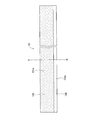
- FIG. 3 is a plan view illustrating a positive electrode plate according to the first embodiment.
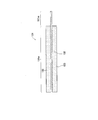
- FIG. 4 is a cross-sectional view of the positive electrode plate taken along the line AA in FIG. 3 according to the first embodiment.
- FIG. 3 is a plan view illustrating the negative electrode plate according to the first embodiment.
- FIG. 6 is a cross-sectional view of the negative electrode plate taken along the line BB in FIG. 5 according to the first embodiment. It is a top view which concerns on Embodiment 1 and shows a separator.
- FIG. 1 is a longitudinal sectional view of a lithium ion secondary battery according to Embodiment 1.
- FIG. FIG. 3 is a perspective view showing a wound electrode body according to the first embodiment.
- FIG. 3 is a plan view illustrating a positive electrode plate according to the
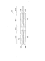
- FIG. 9 is a cross-sectional view of the separator taken along the line CC in FIG. 7 according to the first embodiment.
- FIG. 3 is a plan view illustrating a state in which a positive electrode plate, a negative electrode plate, and a separator are stacked on each other according to the first embodiment.
- FIG. 10 is a cross-sectional view taken along the line DD in FIG. 9 in a state where the positive electrode plate, the negative electrode plate, and the separator are overlapped with each other according to the first embodiment.
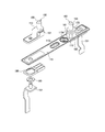
- FIG. 3 is an exploded perspective view illustrating a case lid member, a positive electrode terminal member, a negative electrode terminal member, and the like according to the first embodiment.
- FIG. 6 is a plan view showing a negative electrode plate according to the second embodiment.
- FIG. 13 is a cross-sectional view of the negative electrode plate taken along line EE in FIG. 12 according to the second embodiment.
- FIG. 6 is a plan view showing a positive electrode plate according to the third embodiment.
- FIG. 15 is a cross-sectional view of the positive electrode plate taken along the line FF in FIG. 14 according to the third embodiment.
- 6 is a graph showing the relationship between the number of cycles of a high-rate pulse cycle test and the resistance increase rate for the lithium ion secondary batteries of Examples 1 to 3 and Comparative Examples 1 and 2. It is explanatory drawing which shows the vehicle which concerns on Embodiment 4. FIG. It is explanatory drawing which shows the hammer drill which concerns on Embodiment 5.
- Lithium ion secondary battery non-aqueous electrolyte secondary battery
- 220 320 Winding type electrode body (electrode body) 121, 321 Positive electrode plate 121h, 321h Positive electrode concave region 122 Positive electrode current collector foil 123, 323 Positive electrode active material layer 123f, 323f Outer peripheral edge 131, 231 Negative electrode plate 231h Negative electrode concave region 132 Negative electrode current collector foil 133, 233 Negative electrode active material layer 133f , 233f Outer peripheral edge 141
- Separator 700 Vehicle 800 Hammer drill AX Axis
- FIG. 1 shows a lithium ion secondary battery (nonaqueous electrolyte secondary battery) 100 according to the first embodiment.
- FIG. 2 shows a wound electrode body (electrode body) 120 that constitutes the lithium ion secondary battery 100. Further, the positive electrode plate 121 constituting the wound electrode body 120 is shown in FIGS. 3 and 4, the negative electrode plate 131 is shown in FIGS. 5 and 6, and the separator 141 is shown in FIGS. 9 and 10 show a state in which the positive electrode plate 121 and the negative electrode plate 131 are stacked with the separator 141 interposed therebetween.
- FIG. 11 shows details of the case lid member 113, the positive electrode terminal member 150, the negative electrode terminal member 160, and the like.
- the lithium ion secondary battery 100 is a prismatic battery that is mounted on a vehicle such as a hybrid vehicle or an electric vehicle, or a battery using device such as a hammer drill.
- the lithium ion secondary battery 100 includes a rectangular battery case 110, a wound electrode body 120 accommodated in the battery case 110, a positive electrode terminal member 150 and a negative electrode terminal member 160 supported by the battery case 110. Etc. (see FIG. 1).
- an electrolyte solution (not shown) is injected into the battery case 110.
- the battery case 110 is composed of a box-shaped case main body member 111 opened only on the upper side, and a rectangular plate-shaped case cover member 113 welded in a form to close the opening 111 h of the case main body member 111. ing.
- the case lid member 113 is provided with a safety valve portion 113j that is broken when the internal pressure of the battery case 110 reaches a predetermined pressure (see FIGS. 1 and 11).
- the case lid member 113 is provided with an electrolyte solution inlet 113 d for injecting the electrolyte solution into the battery case 110.
- the positive electrode terminal member 150 and the negative electrode terminal member 160 are fixed to the case lid member 113 via three insulating members 181, 183, and 185, respectively.
- the positive electrode terminal member 150 and the negative electrode terminal member 160 are constituted by three terminal fittings 151, 153, and 155, respectively.
- the positive electrode terminal member 150 is connected to the positive electrode plate 121 of the electrode body 120
- the negative electrode terminal member 160 is connected to the negative electrode plate 131 of the electrode body 120.
- the wound electrode body 120 is housed in an insulating film enclosure 170 formed in a bag shape with only the upper opening of the insulating film, and is housed in the battery case 110 in a laid state (FIG. 1). reference).
- the wound electrode body 120 includes a long positive electrode plate 121 (see FIGS. 3 and 4) and a long negative electrode plate 131 (see FIGS. 5 and 6), which are long and breathable. Are overlapped with each other via the separator 141 (see FIGS. 7 and 8), wound around the axis AX, and compressed into a flat shape (see FIGS. 9, 10 and 2).
- a positive electrode current collector 121 m described later of the positive electrode plate 121 forms a spiral shape from the separator 141. It protrudes.
- a negative electrode current collector 131m described later of the negative electrode plate 131 forms a spiral to form a separator. 141 protrudes.
- the positive electrode plate 121 has a positive electrode current collector foil 122 made of a long aluminum foil as a core material.
- the positive electrode active material layer 123 includes a positive electrode active material, a conductive agent, and a binder.
- a belt-like portion where the positive electrode active material layer 123 exists in the thickness direction of the positive electrode plate 121 is a positive electrode portion 121w.
- the positive electrode portion 121w is in a state where the wound electrode body 120 is configured, and the entire region thereof is opposed to a negative electrode portion 131w of a negative electrode plate 131 described later via a separator 141 (see FIG. 10).
- one end in the width direction (upward in FIG. 3, left side in FIGS. 4 and 10) of the positive electrode current collector foil 122 is strip-shaped in the longitudinal direction.
- the positive electrode current collector 121m extends in the direction.
- the positive electrode plate 121 is in a form that is located on the inner side in the spreading direction of the positive electrode plate 121 than the outer peripheral edge 123f of the positive electrode active material layer 123, that is, does not reach the outer peripheral edge 123f of the positive electrode active material layer 123. It has a positive electrode concave region 121h in the form (see FIG. 3). In the positive electrode concave region 121h, as shown in FIGS. 4 and 10, the positive electrode active material layer 123 does not exist and the positive electrode current collector foil 122 is exposed.
- the positive electrode concave region 121h is a longitudinally-extended positive electrode concave region that extends in the longitudinal direction of the positive electrode plate 121 (the left-right direction in FIG. 3 and the direction orthogonal to the paper surface in FIGS. 4 and 10). This is a central longitudinally-extending positive electrode concave region provided only at the center in the width direction (vertical direction in FIG. 3, horizontal direction in FIGS. 4 and 10) of the positive electrode active material layer 123 having a scale shape.
- the positive electrode recessed region 121 h has a length in the longitudinal direction slightly shorter than the entire length of the positive electrode active material layer 123, and an end portion in the longitudinal direction is located inside the outer peripheral edge 123 f of the positive electrode active material layer 123.
- the width Lq of the positive electrode concave region 121h is 10% of the width Lp of the positive electrode active material layer 123.
- the negative electrode plate 131 includes a negative electrode current collector foil 132 made of a long copper foil as a core material.
- a negative electrode active material layer 133 is provided on each side of the negative electrode current collector foil 132 in a strip shape in the longitudinal direction (FIG. 5, left-right direction, direction orthogonal to the paper surface in FIGS. 6 and 10).
- the negative electrode active material layer 133 includes a negative electrode active material, a binder, and a thickener.
- a band-shaped portion where the negative electrode active material layer 133 exists in the thickness direction of the negative electrode plate 131 is the negative electrode portion 131 w.
- the other end of the negative electrode current collector foil 132 in the width direction extends in the longitudinal direction.
- the negative electrode current collector 131m extends in a strip shape.
- the width of the negative electrode portion 131w is slightly larger than the width Lp of the positive electrode portion 121w.
- the separator 141 (refer FIG.7, FIG8 and FIG.10) consists of well-known resin, and makes long shape.
- the wound electrode body 120 of the lithium ion secondary battery 100 has the positive electrode concave region 121h in the positive electrode plate 121 constituting the lithium ion secondary battery 100.
- the lithium ion secondary battery 100 when a large current is discharged in a low temperature environment, the lithium ion concentration of the electrolyte near the negative electrode active material layer 133 increases and the wound electrode body 120 expands thermally. Along with this, pressure is applied to the electrolytic solution existing in the electrode body, and an attempt is made to push out the electrolytic solution having a high concentration to the outside of the electrode body.
- the positive electrode recessed area 121h is provided in the wound electrode body 120, a high concentration electrolyte can be temporarily accommodated in the positive electrode recessed area 121h. Thereby, while the pressure applied to the electrolyte solution inside an electrode body falls, the quantity of the electrolyte solution extruded outside an electrode body can be suppressed.
- the lithium ion concentration of the electrolyte solution near the negative electrode active material layer 133 decreases and is present in the electrode body due to the thermal expansion of the wound electrode body 120.
- Pressure is applied to the electrolyte solution, and the electrolyte solution having a low concentration tries to be pushed out of the electrode body.
- this low concentration electrolytic solution can be temporarily accommodated in the positive electrode recessed region 121h. Thereby, while the pressure applied to the electrolyte solution inside an electrode body falls, the quantity of the electrolyte solution extruded outside an electrode body can be suppressed.
- the positive electrode concave region 121 h is formed inside the outer peripheral edge 123 f of the positive electrode active material layer 123 and does not communicate with the outside of the positive electrode active material layer 123. For this reason, the high concentration (or low concentration) electrolytic solution temporarily accommodated in the positive electrode recessed region 121h does not flow out of the electrode body, and thus is temporarily accommodated in the positive electrode recessed region 121h.
- the electrolytic solution can quickly return between the positive electrode active material layer 123 and the negative electrode active material layer 133 after the thermal expansion of the wound electrode body 120 has subsided.
- this lithium ion secondary battery 100 even when a large current is repeatedly discharged or charged in a low temperature environment, the lithium ion concentration in the electrolyte inside the electrode body gradually decreases (in the case of discharge), Or the malfunction (in the case of charge) which becomes high gradually can be suppressed.
- the lithium ion concentration in the electrolyte inside the electrode body gradually decreases (in the case of discharge), Or the malfunction (in the case of charge) which becomes high gradually can be suppressed.
- discharging or charging with a large current is repeated in a low temperature environment, it is possible to suppress the apparent battery capacity from being reduced.
- the positive electrode concave region 121h is a region where the positive electrode current collector foil 122 is exposed without the presence of the positive electrode active material layer 123, and thus the positive electrode concave region formed by thinning the positive electrode active material layer 123. Compared to, it is easy to form.
- the electrolyte is mainly The positive electrode active material layer 123 and the negative electrode active material layer 133 are extruded toward the outside in the axis AX direction of the wound electrode body 120.
- the positive electrode active material layer 123 is provided with the positive electrode concave region (longitudinal stretched positive electrode concave region) 121h extending in the longitudinal direction, so that the electrolyte is temporarily applied over a wide range in the longitudinal direction.
- the electrolyte solution in the wound electrode body 120 can be suppressed from being pushed outward in the axis line AX direction (outside in the width direction of the positive electrode plate 121) over a wide range in the longitudinal direction.
- this longitudinally stretched positive electrode recessed region (center longitudinally stretched positive electrode recessed region) 121h is provided in the center of the positive electrode active material layer 123 in the width direction, the width is larger than that provided in a portion other than the center in the width direction.
- the electrolyte can be temporarily stored in a well-balanced direction.
- the area of the positive electrode concave region 121h can be suppressed.
- a decrease in battery capacity due to a decrease in the area of the positive electrode active material layer 123 due to the provision of the positive electrode concave region 121h can be suppressed.
- the width Lq of the central longitudinally elongated positive electrode recessed region 121h is set to 1% or more of the width Lp of the positive electrode active material layer 123, so that it is wound by discharging or charging a large current in a low temperature environment.
- the electrolytic solution in the wound electrode body 120 can be appropriately and temporarily accommodated.
- the width Lq of the central longitudinally stretched positive electrode recessed region 121h was set to 20% or less of the width Lp of the positive electrode active material layer 123.
- the positive electrode plate 121 is manufactured. That is, a positive electrode current collector foil 122 made of a long aluminum foil is prepared. A positive electrode active material containing a positive electrode active material, a conductive material, and a binder is formed on one main surface of the positive electrode current collector foil 122 while forming a strip-like positive electrode current collector portion 121m and a positive electrode concave region 121h extending in the longitudinal direction. A material paste is applied to form a strip-like positive electrode portion 121w.
- a positive electrode active material paste is applied to form a belt-like positive electrode part 121w while forming the belt-like positive electrode current collector part 121m and the positive electrode concave area 121h.
- the positive electrode recessed area 121h and the positive electrode part 121w can be formed by, for example, intermittently applying a positive electrode active material paste in the longitudinal direction. Thereafter, hot air is blown to dry the applied positive electrode active material paste to form the positive electrode active material layer 123.
- the positive electrode active material layer 123 is compressed by a pressure roll.
- the positive electrode plate 121 is formed (see FIGS. 3 and 4).
- the negative electrode plate 131 is manufactured. That is, a negative electrode current collector foil 132 made of a long copper foil is prepared. Then, a negative electrode active material paste containing a negative electrode active material, a binder and a thickener is applied to one main surface of the negative electrode current collector foil 132 while forming a strip-shaped negative electrode current collector portion 131m extending in the longitudinal direction. Thus, a strip-shaped negative electrode portion 131w is formed. Also, a negative electrode active material paste is applied to the main surface on the opposite side of the negative electrode current collector foil 132 while forming a strip-like negative electrode current collector portion 131m to form a strip-like negative electrode portion 131w.
- the negative electrode active material layer 133 is compressed by a pressure roll.
- the negative electrode plate 131 is formed (see FIGS. 5 and 6).
- a long separator body 141 is prepared. Then, the positive electrode plate 121 and the negative electrode plate 131 are overlapped with each other via the separator 141 (see FIGS. 9 and 10), wound around the axis line AX using a winding core, and then compressed into a flat shape and compressed as described above.
- a rotary electrode body 120 is formed (see FIG. 2). Next, a battery is assembled using the wound electrode body 120. Thereafter, an electrolytic solution is injected into the battery case 110 from the electrolytic solution injection port 113d, and the electrolytic solution injection port 113d is sealed. Thus, the lithium ion secondary battery 100 is completed.
- the positive electrode plate 121 is provided with the positive electrode concave region 121h and the negative electrode plate 231 is provided with the negative electrode concave region 231h.
- the negative electrode plate 131 is not provided with the negative electrode concave region.
- it is basically the same as in the first embodiment, and therefore the description of the same parts as in the first embodiment is omitted or simplified.
- the negative electrode plate 231 has a negative electrode current collector foil 132 similar to that of the first embodiment as a core material, on both surfaces of the negative electrode current collector foil 132.
- the negative electrode active material layer 233 is provided in a strip shape in the longitudinal direction (FIG. 12, left-right direction, direction orthogonal to the paper surface in FIG. 13).
- a belt-like portion where the negative electrode active material layer 233 exists in the thickness direction of the negative electrode plate 231 is a negative electrode portion 231 w.
- the other end in the width direction (downward in FIG. 12, right side in FIG. 13) of the negative electrode current collector foil 132 extends in a strip shape in the longitudinal direction. It is a negative electrode current collector 231m.
- the negative electrode plate 231 is closed in a form that is located on the inner side in the spreading direction of the negative electrode plate 231 than the outer peripheral edge 233f of the negative electrode active material layer 233, that is, a form that does not reach the outer peripheral edge 233f of the negative electrode active material layer 233.
- a negative electrode recessed region 231h In this negative electrode concave region 231h, the negative electrode current collector foil 132 is exposed without the negative electrode active material layer 233 being present.
- the negative electrode recessed region 231h is a longitudinally elongated negative electrode recessed region extending in the longitudinal direction of the negative electrode plate 231. Further, only one central longitudinally extending portion is provided at the center in the width direction of the elongated negative electrode active material layer 233.
- the negative electrode recessed region 231 h is slightly shorter in the longitudinal direction than the negative electrode active material layer 233, and the end in the longitudinal direction is located inside the outer peripheral edge 233 f of the negative electrode active material layer 233.
- the lithium ion secondary battery 200 of Embodiment 2 has a positive electrode concave region 121h on the positive electrode plate 121 constituting the wound electrode body 220 and a negative electrode concave region 231h on the negative electrode plate 231. Therefore, in the lithium ion secondary battery 200, when the wound electrode body 220 is thermally expanded by discharging or charging a large current in a low temperature environment, not only the positive electrode concave region 121h but also the negative electrode concave region 231h can be temporarily accommodated.
- the lithium ion secondary battery 200 of the second embodiment has the negative electrode concave region 231h in addition to the positive electrode concave region 121h, it is compared with the lithium ion secondary battery 100 of the first embodiment having only the positive electrode concave region 121h.
- more electrolytic solution can be temporarily stored. Therefore, even when the wound electrode body 220 is thermally expanded by discharging or charging a large current in a low temperature environment, the pressure applied to the electrolyte inside the electrode body can be reduced and the electrolyte solution pushed out of the electrode body Can be suppressed.
- the positive electrode concave region 121h and the negative electrode concave region 231h are formed on the inner side of the outer peripheral edge 123f (or outer peripheral edge 233f) of the positive electrode active material layer 123 (or the negative electrode active material layer 233). 123 (or the negative electrode active material layer 233) does not communicate with the outside. For this reason, the electrolytic solution temporarily accommodated in the positive electrode concave region 121h and the negative electrode concave region 231h does not flow out of the electrode body, and immediately after the thermal expansion of the wound electrode body 220 subsides. It can return between the positive electrode active material layer 123 and the negative electrode active material layer 233.
- the lithium ion secondary battery 200 even when a large current is repeatedly discharged or charged in a low temperature environment, changes in the lithium ion concentration in the electrolyte solution inside the electrode body can be suppressed. Thus, even when discharging or charging with a large current is repeated in a low temperature environment, it is possible to suppress the apparent battery capacity from being reduced.
- the same parts as those of the first embodiment have the same effects as those of the first embodiment.
- the positive electrode plate 321 has a positive electrode current collector foil 122 similar to that of the first embodiment as a core material, on both surfaces of the positive electrode current collector foil 122.
- the positive electrode active material layer 323 is provided in a strip shape in the longitudinal direction (the left-right direction in FIG. 14, the direction orthogonal to the paper surface in FIG. 15).
- a belt-like portion where the positive electrode active material layer 323 exists in the thickness direction of the positive electrode plate 321 is the positive electrode portion 321 w.
- one end in the width direction (upward in FIG. 14, left side in FIG. 15) of the positive electrode current collector foil 122 is a positive electrode extending in a strip shape in the longitudinal direction. It is a current collector 321m.
- the positive electrode 321 has a configuration in which the positive electrode plate 321 is located on the inner side in the spreading direction of the positive electrode plate 321 than the outer peripheral edge 323f of the positive electrode active material layer 323, that is, the positive electrode plate 321f does not reach the outer peripheral edge 323f of the positive electrode active material layer 323.
- a plurality of concave regions 321h are provided. These positive electrode concave regions 321h are formed by forming a part of the positive electrode active material layer 323 thin.
- Each positive electrode concave region 321 h has a rectangular shape in plan view extending in the longitudinal direction of the positive electrode plate 321.
- Each of the positive electrode concave regions 321h, 321h,... Is located at the center in the width direction (vertical direction in FIG. 14, vertical direction in FIG. 15, left and right direction in FIG. 15) of the elongated positive electrode active material layer 323 and has a predetermined gap. Then, they are aligned in the longitudinal direction of the positive electrode plate 321 in
- regions 321h, 321h, ... can be provided by press molding, for example. That is, a positive electrode current collector foil 122 made of a long aluminum foil is prepared, and a positive electrode active material paste is applied to one main surface of the positive electrode current collector foil 321 m while forming a strip-like positive electrode current collector portion 321 m. Is formed into a solid shape. Further, the positive electrode active material paste is applied to the main surface on the opposite side of the positive electrode current collector foil 122 while forming the strip-like positive electrode current collector part 321m, so that the positive electrode part 321w is formed in a solid shape.
- the positive electrode plate 321 is formed.
- the positive electrode concave regions 321h, 321h,... Can be formed by partially reducing the thickness of the coating film.
- the wound electrode body 320 is formed by discharging or charging a large current in a low temperature environment.
- the electrolytic solution can be temporarily accommodated in these positive electrode recessed regions 321h, 321h,. Therefore, even when the wound electrode body 320 is thermally expanded by discharging or charging a large current in a low temperature environment, the pressure applied to the electrolyte solution inside the electrode body can be lowered and the electrolyte solution pushed out of the electrode body Can be suppressed.
- these positive electrode recessed regions 321h, 321h,... are all formed inside the outer peripheral edge 323f of the positive electrode active material layer 323 and do not communicate with the outside of the positive electrode active material layer 323. For this reason, the electrolyte solution temporarily accommodated in these positive electrode concave regions 321h, 321h,... Does not flow out of the electrode body, and immediately after the thermal expansion of the wound electrode body 320 has subsided. It can return between the positive electrode active material layer 323 and the negative electrode active material layer 133.
- the lithium ion secondary battery 300 even when a large current is repeatedly discharged or charged in a low temperature environment, changes in the lithium ion concentration in the electrolytic solution inside the electrode body can be suppressed. Thus, even when discharging or charging with a large current is repeated in a low temperature environment, it is possible to suppress the apparent battery capacity from being reduced.
- the same parts as those in the first or second embodiment have the same effects as those in the first or second embodiment.
- Example 1 the result of the test conducted in order to verify the effect of this invention is demonstrated.
- the width Lq (5 mm) of the positive electrode recessed region 121h in Example 1 is 10% of the width Lp (50 mm) of the positive electrode active material layer 123.
- the width Lq (2 mm) of the positive electrode recessed area in Example 2 is 4% of the width Lp (50 mm) of the positive electrode active material layer 123
- the width Lq (1 mm) of the positive electrode recessed area in Example 3 is. Is 2% of the width Lp (50 mm) of the positive electrode active material layer 123.
- Comparative Example 1 a lithium ion secondary battery was prepared in the same manner as in Embodiment 1 except that the positive electrode recessed region was not provided.
- Comparative Example 2 a lithium ion secondary battery formed in the same manner as in Embodiment 1 except that a grid-like positive electrode concave region communicating with the outside in the longitudinal direction and the width direction was provided.
- the positive electrode active material layer has a width of 2 mm, an interval of 15 mm extending from the end of the positive electrode active material layer 123 to the end (from the opposite outer peripheral edge 123f to the outer peripheral edge 123f).
- a positive electrode concave region having a form of a width of 2 mm and an interval of 40 mm extending from end to end of the positive electrode active material layer 123 (from the facing outer peripheral edge 123f to the outer peripheral edge 123f) was formed.
- each lithium ion secondary battery 100 or the like is adjusted to 60% SOC (State of Charge), and an initial open circuit voltage is obtained in an environment of ⁇ 15 ° C. Thereafter, the battery was discharged at a constant current of 20 C, the battery voltage at 10 seconds after the start of discharge was obtained, and the initial IV resistance Ro due to the internal resistance was determined from the difference from the initial open circuit voltage. Adjustment to make the SOC 60% was performed by CCCV (1C, CV is 10 minutes) with OCV of SOC 60% after complete discharge at 1C.
- SOC State of Charge
- each of the lithium ion secondary batteries 100 and the like was adjusted again to SOC 60%, and the following charge / discharge cycle consisting of (1) to (4) was repeated under an environment of ⁇ 15 ° C.
- the number of charge / discharge cycles increases and the resistance increase rate tends to increase gradually. It was milder than the ion secondary battery.
- the resistance increase rate exceeds 40% in the lithium ion secondary batteries of Comparative Examples 1 and 2, whereas the resistance increases in the lithium ion secondary battery 100 of Example 1.
- the increase rate is about 11%
- the resistance increase rate is about 13% in the lithium ion secondary battery of Example 2
- the resistance increase rate is about 20% in the lithium ion secondary battery of Example 3
- the resistance increase rate is compared. It can be seen that the lithium ion secondary batteries of Examples 1 and 2 remain about one-quarter to one-half of the lithium ion secondary battery.
- the concentration of the wound electrode body 120 or the like is increased when the wound electrode body 120 or the like is thermally expanded due to a large current (20 C) discharge in a low temperature environment ( ⁇ 15 ° C.). Since the high electrolytic solution is temporarily stored in the positive electrode recessed region 121h or the like that is not communicated with the outside of the electrode body, the amount of the electrolytic solution pushed out of the electrode body can be suppressed. For this reason, even when discharging with a large current (20 C) in a low temperature environment ( ⁇ 15 ° C.) is repeated, it is possible to suppress a decrease in the lithium ion concentration of the electrolytic solution inside the electrode body. As a result, it is considered that the increase in resistance increase rate was suppressed.
- the increase in the resistance increase rate of the lithium ion secondary battery 100 according to Example 1 is the slowest, and then the resistance increase rate of the lithium ion secondary battery according to Example 2
- the rise was moderate.
- the larger the width Lq of the positive electrode recessed area 121h and the like the more the electrolyte solution is discharged when the wound electrode body 120 or the like is thermally expanded due to a large current (20C) discharge in a low temperature environment ( ⁇ 15 ° C.). Since it can be temporarily accommodated, it is considered that the increase in the resistance increase rate becomes milder as the width Lq of the positive electrode concave region 121h and the like is larger.
- the lithium ion secondary battery of Example 2 and the lithium ion secondary battery of Example 3 are compared with the difference in resistance increase rate between the lithium ion secondary battery 100 of Example 1 and the lithium ion secondary battery of Example 2. It can be seen that the difference in the resistance increase rate of the secondary battery increases.
- the width Lq of the positive electrode recessed region 121h and the like is preferably 20% or less of the width Lp of the positive electrode active material layer 123. This is because a decrease in battery capacity due to a decrease in the area of the positive electrode active material layer 123 due to the provision of the positive electrode concave region 121h and the like can be suppressed.
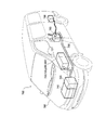
- a vehicle 700 according to the fourth embodiment includes a plurality of the lithium ion secondary batteries 100 according to the first embodiment, and is driven by using an engine 740, a front motor 720, and a rear motor 730 in combination as shown in FIG. It is a hybrid car.
- the vehicle 700 includes a vehicle body 790, an engine 740, a front motor 720, a rear motor 730, a cable 750, and an inverter 760 attached thereto. Further, the vehicle 700 includes an assembled battery 710 having a plurality of lithium ion secondary batteries 100 therein, and the electric energy stored in the assembled battery 710 is used for driving the front motor 720 and the rear motor 730. ing.
- the lithium ion secondary battery 100 can suppress the apparent battery capacity from being reduced even when a large current is repeatedly discharged or charged in a low temperature environment. Therefore, the performance of the vehicle 700 equipped with the lithium ion secondary battery 100 can be maintained high for a long period.
- the lithium ion secondary batteries 200 and 300 of the second or third embodiment may be mounted.
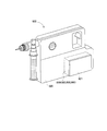
- the hammer drill 800 according to the fifth embodiment is a battery using device on which a battery pack 810 including the lithium ion secondary battery 100 according to the first embodiment is mounted. Specifically, in this hammer drill 800, a battery pack 810 is accommodated in a bottom portion 821 of a main body 820, and this battery pack 810 is used as an energy source for driving the drill.
- the lithium ion secondary battery 100 can suppress the apparent battery capacity from being reduced even when a large current is repeatedly discharged or charged in a low temperature environment. Therefore, the performance of the hammer drill 800 equipped with the lithium ion secondary battery 100 can be maintained high over a long period of time.
- the lithium ion secondary batteries 200 and 300 of the second or third embodiment may be mounted.
- the present invention has been described with reference to the first to fifth embodiments.
- the present invention is not limited to the above-described first to fifth embodiments, and can be appropriately modified and applied without departing from the scope of the present invention.
- the electrode body is a flat wound electrode body 120, 320, 320, but the form of the electrode body is not limited to this.
- the electrode body can be a cylindrical wound electrode body.
- the electrode body may be a stacked electrode body in which a positive electrode plate and a negative electrode plate are stacked on each other with a separator interposed therebetween.
Landscapes
- Chemical & Material Sciences (AREA)
- Engineering & Computer Science (AREA)
- Manufacturing & Machinery (AREA)
- Chemical Kinetics & Catalysis (AREA)
- Electrochemistry (AREA)
- General Chemical & Material Sciences (AREA)
- Materials Engineering (AREA)
- Secondary Cells (AREA)
- Battery Electrode And Active Subsutance (AREA)
Abstract
本発明は、低温環境下での大電流の放電或いは充電を繰り返しによって、見掛けの電池容量が小さくなるのを抑制できる非水電解液二次電池、並びに、この非水電解液二次電池を搭載した車両及び電池使用機器を提供することを 目的とする。 本発明は、正極集電箔(122)及び正極活物質層(123)を含む正極板(121)と、負極集電箔(132)及び負極活物質層(133)を含む負極板(131)とを、セパレータ(141)を介して捲回した捲回型電極体(120)を備えるリチウムイオン二次電池(非水電解液二次電池)(100)であって、捲回型電極体(120)が、正極板(121)に、正極活物質層(123)の外周縁(123f)よりも、正極板(121)の拡がり方向内側に形成され、正極活物質層(123)が薄くされてなるか、または正極活物質層(123)が存在しないで正極集電箔(123)が露出してなる正極凹領域(121h)を有するリチウムイオン二次電池、このリチウムイオン二次電池を搭載した車両及び電池使用機器に関する。
Description
本発明は、正極板と負極板とをセパレータを介して捲回しまたは積層してなる電極体を備える非水電解液二次電池に関する。また、この非水電解液二次電池を搭載する車両及び電池使用機器に関する。
従来より、正極板と負極板とをセパレータを介して捲回しまたは積層してなる電極体を備える非水電解液二次電池が知られている。正極板は、正極集電箔上に正極活物質層が形成されており、負極板は、負極集電箔上に負極活物質層が形成されている。更に、この非水電解液二次電池において、正極板や負極板の正極活物質層や負極活物質層(以下、単に「活物質層」とも言う)に、凹溝を設けたものが知られている。電池の製造の際に、この凹溝を通じて、電解液が電極体内に含浸し易くするためである。或いは、電池の使用時に、この凹溝を通じて、電解液が電極体の内部や電極体の内部と外部との間を流通し易くするためである。例えば特許文献1~3に、活物質層にこのような凹溝を設けたものが開示されている。
具体的には、特許文献1~3には、長尺状の正極板と長尺状の負極板とを長尺状のセパレータを介して捲回した捲回型電極体を備える非水電解液二次電池が開示されている(特許文献1の図1等、特許文献2の図6等、特許文献3の図7等を参照)。加えて、特許文献3には、矩形状の正極板と矩形状の負極板とを矩形状のセパレータを介して複数層積層した積層型電極体を備える非水電解液二次電池も開示されている(特許文献3の図4等を参照)。
特許文献1,2の非水電解液二次電池では、活物質層にその幅方向に延びる凹溝が多数形成されている(特許文献1の図2等、特許文献2の図1等を参照)。また、これらの特許文献1,2には、活物質層に格子状に多数の凹溝を形成する形態も開示されている(特許文献1の図4等、特許文献2の図2等を参照)。
一方、特許文献3の非水電解液二次電池では、捲回型電極体を構成する正極板や負極板において、活物質層に長手方向に延びる凹溝が形成されている(特許文献3の図1等を参照)。また、この特許文献3には、積層型電極体を構成する正極板や負極板において、活物質層にその長辺に沿って延びる凹溝が形成されている(特許文献3の図4等を参照)。
一方、特許文献3の非水電解液二次電池では、捲回型電極体を構成する正極板や負極板において、活物質層に長手方向に延びる凹溝が形成されている(特許文献3の図1等を参照)。また、この特許文献3には、積層型電極体を構成する正極板や負極板において、活物質層にその長辺に沿って延びる凹溝が形成されている(特許文献3の図4等を参照)。
これら特許文献1~3に示された凹溝は、いずれも、凹溝の両端が活物質層の外周縁まで形成されている(凹溝が活物質層の端から端まで形成されている)ので、電極体を構成した状態で電極体外部と連通している。これにより、電池の製造の際には、この凹溝を通じて、電解液が電極体内に含浸し易くなる旨が記載されている。また、電池の使用時には、この凹溝を通じて、電解液が電極体の内部や電極体の内部と外部との間を流通し易くなる旨が記載されている。
ところで、凹溝を設けることなく、活物質層をベタ状に形成した従来のリチウムイオン二次電池では、低温環境下で大電流の放電を行うと、電極体の熱膨張に伴い、電極体内に存在する電解液に圧力が掛かる。一方、放電に伴って負極活物質層付近の電解液のリチウムイオン濃度が上がり、この濃度の高い電解液が、電極体の内部から外部に押し出される。従って、低温環境下で大電流の放電を繰り返すと、電極体内部の電解液のリチウムイオン濃度が徐々に低くなる現象が生じる。そうすると、電極体内部で電池反応に寄与し得るリチウムイオンが少なくなるので、見掛けの電池容量が小さくなってしまう。
これとは逆に、このリチウムイオン二次電池において、低温環境下で大電流の充電を行うと、電極体の熱膨張に伴い、電極体内に存在する電解液に圧力が掛かる。一方、充電に伴って負極活物質層付近の電解液のリチウムイオン濃度が下がり、この濃度の低い電解液が、電極体の内部から外部に押し出される。従って、低温環境下で大電流の充電を繰り返すと、電極体内部の電解液のリチウムイオン濃度が徐々に高くなる現象が生じる。そうすると、電極体内部の電解液のリチウムイオン濃度が好適な範囲を超えるので、この場合も、電池反応が低下し、見掛けの電池容量が小さくなってしまう。
このように、従来のリチウムイオン二次電池などの非水電解液二次電池では、低温環境下で大電流の放電或いは充電を繰り返すと、見掛けの電池容量が小さくなるという問題があった。
このように、従来のリチウムイオン二次電池などの非水電解液二次電池では、低温環境下で大電流の放電或いは充電を繰り返すと、見掛けの電池容量が小さくなるという問題があった。
本発明は、かかる現状に鑑みてなされたものであって、低温環境下での大電流の放電或いは充電を繰り返しによって、見掛けの電池容量が小さくなるのを抑制できる非水電解液二次電池、並びに、この非水電解液二次電池を搭載した車両及び電池使用機器を提供することを目的とする。
上記課題を解決するための本発明の一態様は、正極集電箔及びこの上に形成された正極活物質層を含む正極板と、負極集電箔及びこの上に形成された負極活物質層を含む負極板と、セパレータとを有し、前記正極板と前記負極板とを前記セパレータを介して捲回しまたは積層してなる電極体を備える非水電解液二次電池であって、前記電極体は、前記正極板に、前記正極活物質層の外周縁よりも、前記正極板の拡がり方向内側に形成され、前記正極活物質層が薄くされてなるか、または、前記正極活物質層が存在しないで前記正極集電箔が露出してなる、一又は複数の正極凹領域、及び、前記負極板に、前記負極活物質層の外周縁よりも、前記負極板の拡がり方向内側に形成され、前記負極活物質層が薄くされてなるか、または、前記負極活物質層が存在しないで前記負極集電箔が露出してなる、一又は複数の負極凹領域、の少なくともいずれかを有する非水電解液二次電池である。
この非水電解液二次電池は、活物質層の外周縁よりも内側に位置する形態、即ち、活物質層の外周縁までは届かない形態の正極凹領域及び負極凹領域の少なくともいずれかを有する。このため、この非水電解液二次電池では、低温環境下での大電流の放電或いは充電により電極体が熱膨張したときに、濃度の高い(或いは低い)電解液をこの正極凹領域や負極凹領域に一時的に収容できる。これにより、電極体内部の電解液に掛かる圧力が下がると共に、電極体外部に押し出される電解液の量を抑制できる。
ところで、前述の活物質層に凹溝を設けた従来技術に係る非水電解液二次電池も、電極体が熱膨張したときに、この凹溝に濃度の高い(或いは低い)電解液を一時的に収容でき、電極体内部の電解液に掛かる圧力を下げることができる。しかし、この凹溝は、活物質層の外部まで連通しているので、凹溝に収容された電解液が外部へ流出し易い。
これに対し、上述の非水電解液二次電池では、正極凹領域や負極凹領域は、活物質層の外周縁よりも内側に形成されており、活物質層の外部に連通していない。このため、この正極凹領域や負極凹領域に一時的に収容された電解液が、電極体外部に流出することもない。
これに対し、上述の非水電解液二次電池では、正極凹領域や負極凹領域は、活物質層の外周縁よりも内側に形成されており、活物質層の外部に連通していない。このため、この正極凹領域や負極凹領域に一時的に収容された電解液が、電極体外部に流出することもない。
従って、この非水電解液二次電池では、低温環境下で大電流の放電或いは充電を繰り返したときに、電極体内部の電解液中のリチウムイオンなど電気伝導を担うイオンの濃度が変化するのを抑制できる。かくして、低温環境下での大電流の放電或いは充電を繰り返しによって、見掛けの電池容量が小さくなるのを抑制できる。
更に、上記の非水電解液二次電池であって、前記正極凹領域及び前記負極凹領域のうち、前記正極凹領域のみを有する非水電解液二次電池とすると良い。
前述の負極凹領域を設けたリチウムイオン二次電池では、低温環境下で大電流の充電を繰り返したときに、この負極凹領域の周囲の負極活物質層に金属Liが析出するおそれがある。負極凹領域では、負極活物質層が、薄くなっているかまたは存在しない。このため、充電時に正極活物質層から放出され、負極活物質層に向かって移動したリチウムイオンは、負極凹領域にはドープされ難いかドープされない。このため、負極凹領域の周囲の負極活物質層には、より多くのリチウムイオンが集まるので、この部分で金属Liが析出し易くなるものと考えられる。
これに対し、上述の非水電解液二次電池では、負極凹領域は設けないで、正極凹領域のみを設けている。従って、非水電解液二次電池をリチウムイオン二次電池としても、上述のような金属Liの析出を防止できると共に、低温環境下での大電流の放電或いは充電を繰り返しによって、見掛けの電池容量が小さくなるのを抑制できる。
更に、上記の非水電解液二次電池であって、前記正極凹領域は、前記正極活物質層が存在しないで前記正極集電箔が露出してなる非水電解液二次電池とすると良い。
この非水電解液二次電池では、正極凹領域を、正極活物質層が存在しないで正極集電箔が露出した形態としているので、正極活物質層を薄くして形成した正極凹領域に比して、形成容易である。
更に、上記のいずれかに記載の非水電解液二次電池であって、前記電極体は、長尺状の前記正極板と、長尺状の前記負極板とを、長尺状の前記セパレータを介して捲回した捲回型電極体であり、前記正極凹領域は、前記正極板の長手方向に延びる長手延伸正極凹領域である非水電解液二次電池とすると良い。
捲回型電極体を有する非水電解液二次電池においては、低温環境下での大電流の放電或いは充電により捲回型電極体が熱膨張したとき、電解液は、主に、活物質層から捲回型電極体の軸線方向外側に向けて押し出される。これに対し、正極活物質層内にその長手方向に延びる正極凹領域(長手延伸正極凹領域)を設ければ、長手方向の広い範囲にわたって電解液を一時的に収容でき、長手方向の広い範囲にわたって捲回型電極体中の電解液が軸線方向外側(正極板の幅方向外側)に押し出されるのを抑制できる。かくして、この非水電解液二次電池では、低温環境下での大電流の放電或いは充電を繰り返しによって、見掛けの電池容量が小さくなるのを、より効果的に抑制できる。
更に、上記の非水電解液二次電池であって、前記正極板は、前記長手延伸正極凹領域を1つのみ有し、この長手延伸正極凹領域は、長尺状の前記正極活物質層の幅方向中央に設けられた中央長手延伸正極凹領域である非水電解液二次電池とすると良い。
前述したように、捲回型電極体を有する非水電解液二次電池においては、低温環境下での大電流の放電或いは充電により捲回型電極体が熱膨張したときに、電解液は、主に、活物質層から捲回型電極体の軸線方向外側(正極板の幅方向外側)に向けて押し出される。従って、長手延伸正極凹領域(中央長手延伸正極凹領域)を、正極活物質層の幅方向中央に設ければ、幅方向中央以外の部位に設ける場合に比して、幅方向にバランス良く電解液を一時的に収容できる。よって、この非水電解液二次電池では、低温環境下での大電流の放電或いは充電を繰り返しによって、見掛けの電池容量が小さくなるのを、更に効果的に抑制できる。
しかも、長手延伸正極凹領域(中央長手延伸正極凹領域)を1つのみとしているので、正極凹領域の面積を抑制できる。かくして、正極凹領域を設けることによる正極活物質層の面積減少に伴う電池容量の減少を抑制できる。
しかも、長手延伸正極凹領域(中央長手延伸正極凹領域)を1つのみとしているので、正極凹領域の面積を抑制できる。かくして、正極凹領域を設けることによる正極活物質層の面積減少に伴う電池容量の減少を抑制できる。
更に、上記の非水電解液二次電池であって、前記中央長手延伸正極凹領域の幅を、前記正極活物質層の幅の1~20%の大きさにしてなる非水電解液二次電池とすると良い。
この非水電解液二次電池では、中央長手延伸正極凹領域の幅を正極活物質層の幅の1%以上としているので、低温環境下での大電流の放電或いは充電により捲回型電極体が熱膨張したときに、電解液を適切に一時的に収容できる。
一方、中央長手延伸正極凹領域の幅を正極活物質層の幅の20%以下とした。これにより、中央長手延伸正極凹領域を設けたことに伴う正極活物質層の面積の減少による、電池容量の減少を抑制できる。かくして、この非水電解液二次電池では、当初からの電池容量の減少を抑えると共に、低温環境下での大電流の放電或いは充電を繰り返しによって、見掛けの電池容量が小さくなるのを、より効果的に抑制できる。
なお、中央長手延伸正極凹領域の幅を正極活物質層の幅の3%以上とするのが、電解液をより適切に一時的に収容できる点で、更に好ましい。
一方、中央長手延伸正極凹領域の幅を正極活物質層の幅の20%以下とした。これにより、中央長手延伸正極凹領域を設けたことに伴う正極活物質層の面積の減少による、電池容量の減少を抑制できる。かくして、この非水電解液二次電池では、当初からの電池容量の減少を抑えると共に、低温環境下での大電流の放電或いは充電を繰り返しによって、見掛けの電池容量が小さくなるのを、より効果的に抑制できる。
なお、中央長手延伸正極凹領域の幅を正極活物質層の幅の3%以上とするのが、電解液をより適切に一時的に収容できる点で、更に好ましい。
また、他の態様は、上記のいずれかに記載の非水電解液二次電池を搭載し、この非水電解液二次電池に蓄えた電気エネルギを、駆動源の駆動エネルギの全部または一部として使用する車両である。
前述の非水電解液二次電池は、低温環境下での大電流の放電或いは充電を繰り返しによって、見掛けの電池容量が小さくなることを抑制できるので、この非水電解液二次電池を搭載する車両の性能を、長期間にわたり高く維持できる。
なお、「車両」としては、例えば、電気自動車、ハイブリッド自動車、プラグインハイブリッド自動車、ハイブリッド鉄道車両、フォークリフト、電気車いす、電動アシスト自転車、電動スクータなどが挙げられる。
なお、「車両」としては、例えば、電気自動車、ハイブリッド自動車、プラグインハイブリッド自動車、ハイブリッド鉄道車両、フォークリフト、電気車いす、電動アシスト自転車、電動スクータなどが挙げられる。
また、他の態様は、上記のいずれかに記載の非水電解液二次電池を搭載し、この非水電解液二次電池をエネルギ源の少なくとも1つとして使用する電池使用機器である。
前述の非水電解液二次電池は、低温環境下での大電流の放電或いは充電を繰り返しによって、見掛けの電池容量が小さくなることを抑制できるので、この非水電解液二次電池を搭載する電池使用機器の性能を、長期間にわたり高く維持できる。
なお、「電池使用機器」としては、例えば、パーソナルコンピュータ、携帯電話、電池駆動の電動工具、無停電電源装置など、電池で駆動される各種の家電製品、オフィス機器、産業機器などが挙げられる。
なお、「電池使用機器」としては、例えば、パーソナルコンピュータ、携帯電話、電池駆動の電動工具、無停電電源装置など、電池で駆動される各種の家電製品、オフィス機器、産業機器などが挙げられる。
100,200,300 リチウムイオン二次電池(非水電解液二次電池)
120,220,320 捲回型電極体(電極体)
121,321 正極板
121h,321h 正極凹領域
122 正極集電箔
123,323 正極活物質層
123f,323f 外周縁
131,231 負極板
231h 負極凹領域
132 負極集電箔
133,233 負極活物質層
133f,233f 外周縁
141 セパレータ
700 車両
800 ハンマードリル
AX 軸線
120,220,320 捲回型電極体(電極体)
121,321 正極板
121h,321h 正極凹領域
122 正極集電箔
123,323 正極活物質層
123f,323f 外周縁
131,231 負極板
231h 負極凹領域
132 負極集電箔
133,233 負極活物質層
133f,233f 外周縁
141 セパレータ
700 車両
800 ハンマードリル
AX 軸線
(実施形態1)
以下、本発明の実施の形態を、図面を参照しつつ説明する。図1に、本実施形態1に係るリチウムイオン二次電池(非水電解液二次電池)100を示す。また、図2に、このリチウムイオン二次電池100を構成する捲回型電極体(電極体)120を示す。更に、この捲回型電極体120を構成する正極板121を図3及び図4に示し、負極板131を図5及び図6に示し、セパレータ141を図7及び図8に示す。また、図9及び図10に、正極板121と負極板131とをセパレータ141を介して重ねた状態を示す。また、図11に、ケース蓋部材113、正極電極端子部材150及び負極電極端子部材160等の詳細を示す。
以下、本発明の実施の形態を、図面を参照しつつ説明する。図1に、本実施形態1に係るリチウムイオン二次電池(非水電解液二次電池)100を示す。また、図2に、このリチウムイオン二次電池100を構成する捲回型電極体(電極体)120を示す。更に、この捲回型電極体120を構成する正極板121を図3及び図4に示し、負極板131を図5及び図6に示し、セパレータ141を図7及び図8に示す。また、図9及び図10に、正極板121と負極板131とをセパレータ141を介して重ねた状態を示す。また、図11に、ケース蓋部材113、正極電極端子部材150及び負極電極端子部材160等の詳細を示す。
このリチウムイオン二次電池100は、ハイブリッド自動車や電気自動車等の車両や、ハンマードリル等の電池使用機器に搭載される角型電池である。このリチウムイオン二次電池100は、角型の電池ケース110、この電池ケース110内に収容された捲回型電極体120、電池ケース110に支持された正極電極端子部材150及び負極電極端子部材160等から構成されている(図1参照)。また、電池ケース110内には、図示しない電解液が注入されている。
このうち、電池ケース110は、上側のみが開口した箱状のケース本体部材111と、このケース本体部材111の開口111hを閉塞する形態で溶接された矩形板状のケース蓋部材113とから構成されている。ケース蓋部材113には、電池ケース110の内圧が所定圧力に達した際に破断する安全弁部113jが設けられている(図1及び図11参照)。また、ケース蓋部材113には、電解液を電池ケース110内に注入する為の電解液注入口113dが設けられている。
また、ケース蓋部材113には、正極電極端子部材150と負極電極端子部材160とが、それぞれ3つの絶縁部材181,183,185を介して固設されている。これら正極電極端子部材150及び負極電極端子部材160は、それぞれ3つの端子金具151,153,155により構成されている。電池ケース110内において、正極電極端子部材150は、電極体120の正極板121に接続され、負極電極端子部材160は、電極体120の負極板131に接続されている。
次に、捲回型電極体120について説明する。この捲回型電極体120は、絶縁フィルムを上側のみが開口した袋状に形成した絶縁フィルム包囲体170内に収容され、横倒しにした状態で、電池ケース110内に収容されている(図1参照)。この捲回型電極体120は、長尺状の正極板121(図3及び図4参照)と長尺状の負極板131(図5及び図6参照)とを、通気性を有する長尺状のセパレータ141(図7及び図8参照)を介して互いに重ねて軸線AX周りに捲回し、扁平状に圧縮したものである(図9、図10及び図2参照)。
捲回型電極体120の軸線AX方向一方側(図1中、左側、図2中、上方)には、正極板121のうち後述する正極集電部121mが、渦巻き状をなしてセパレータ141から突出している。一方、捲回型電極体120の軸線AX方向他方側(図1中、右側、図2中、下方)には、負極板131のうち後述する負極集電部131mが、渦巻き状をなしてセパレータ141から突出している。
このうち、正極板121は、図3、図4及び図10に示すように、芯材として、長尺状のアルミニウム箔からなる正極集電箔122を有する。この正極集電箔122の両面には、それぞれ、正極活物質層123が、長手方向(図3中、左右方向、図4及び図10中、紙面に直交する方向)に幅Lp=50mmの帯状に設けられている。正極活物質層123は、正極活物質、導電剤及び結着剤からなる。
正極板121のうち、自身の厚み方向に正極活物質層123が存在する帯状の部位が、正極部121wである。この正極部121wは、捲回型電極体120を構成した状態で、その全域がセパレータ141を介して、後述する負極板131の負極部131wと対向している(図10参照)。また、正極板121に正極部121wを形成したことに伴い、正極集電箔122のうち、幅方向の一端(図3中、上方、図4及び図10中、左側)は、長手方向に帯状に延びる正極集電部121mとなっている。
また、この正極板121は、正極活物質層123の外周縁123fよりも、正極板121の拡がり方向内側に位置する形態の、即ち、正極活物質層123の外周縁123fまでは届かない閉じた形態の正極凹領域121hを有する(図3参照)。この正極凹領域121hでは、図4及び図10に示すように、正極活物質層123が存在せず正極集電箔122が露出している。
また、この正極凹領域121hは、正極板121の長手方向(図3中、左右方向、図4及び図10中、紙面に直交する方向)に延びる長手延伸正極凹領域であり、更には、長尺状をなす正極活物質層123の幅方向(図3中、上下方向、図4及び図10中、左右方向)中央に1つのみ設けられた中央長手延伸正極凹領域である。この正極凹領域121hは、正極活物質層123の全長よりも長手方向の寸法が若干短くされて、長手方向の端部が正極活物質層123の外周縁123fよりも内側に位置する。また、この正極凹領域121hの幅Lqは、Lq=5mmである。前述のように、正極活物質層123の幅LpはLp=50mmであるので、正極凹領域121hの幅Lqは、正極活物質層123の幅Lpの10%の大きさとなっている。
次に、負極板131について説明する。負極板131は、図5、図6及び図10に示すように、芯材として、長尺状の銅箔からなる負極集電箔132を有する。この負極集電箔132の両面には、それぞれ、負極活物質層133が、長手方向(図5、左右方向、図6及び図10中、紙面に直交する方向)に帯状に設けられている。負極活物質層133は、負極活物質、結着剤及び増粘剤からなる。
負極板131のうち、自身の厚み方向に負極活物質層133が存在する帯状の部位が、負極部131wである。また、負極板131に負極部131wを形成したことに伴い、負極集電箔132のうち、幅方向の他端(図5中、下方、図6及び図10中、右側)は、長手方向に帯状に延びる負極集電部131mとなっている。なお、負極部131wの幅は、正極部121wの幅Lpよりも若干大きくされている。
また、セパレータ141(図7、図8及び図10参照)は、公知の樹脂からなり、長尺状をなす。
以上で説明したように、このリチウムイオン二次電池100の捲回型電極体120は、自身を構成する正極板121に正極凹領域121hを有する。
また、セパレータ141(図7、図8及び図10参照)は、公知の樹脂からなり、長尺状をなす。
以上で説明したように、このリチウムイオン二次電池100の捲回型電極体120は、自身を構成する正極板121に正極凹領域121hを有する。
ところで、このリチウムイオン二次電池100では、低温環境下で大電流の放電を行うと、負極活物質層133付近の電解液のリチウムイオン濃度が上がると共に、捲回型電極体120の熱膨張に伴って電極体内に存在する電解液に圧力が掛かり、濃度の高い電解液を電極体外部に押し出そうとする。しかし、本実施形態1では、捲回型電極体120に正極凹領域121hを設けているので、濃度の高い電解液を、この正極凹領域121hに一時的に収容できる。これにより、電極体内部の電解液に掛かる圧力が下がると共に、電極体外部に押し出される電解液の量を抑制できる。
一方、低温環境下で大電流の充電を行った場合には、負極活物質層133付近の電解液のリチウムイオン濃度が下がると共に、捲回型電極体120の熱膨張に伴って電極体内に存在する電解液に圧力が掛かり、濃度の低い電解液を電極体外部に押し出そうとする。しかし、本実施形態1では、この濃度の低い電解液を、正極凹領域121hに一時的に収容できる。これにより、電極体内部の電解液に掛かる圧力が下がると共に、電極体外部に押し出される電解液の量を抑制できる。
しかも、正極凹領域121hは、正極活物質層123の外周縁123fよりも内側に形成されており、正極活物質層123の外部に連通していない。このため、この正極凹領域121hに一時的に収容された濃度の高い(或いは濃度の低い)電解液が、電極体外部に流出することがないため、正極凹領域121hに一時的に収容された電解液は、捲回型電極体120の熱膨張が治まった後、速やかに正極活物質層123と負極活物質層133との間に戻ることができる。
従って、このリチウムイオン二次電池100では、低温環境下で大電流の放電或いは充電を繰り返し行った場合でも、電極体内部の電解液のリチウムイオン濃度が徐々に低くなる不具合(放電の場合)、或いは徐々に高くなる不具合(充電の場合)を抑制できる。かくして、低温環境下で大電流の放電或いは充電を繰り返した場合でも、見掛けの電池容量が小さくなるのを抑制できる。
更に、本実施形態1では、正極凹領域121hは、正極活物質層123が存在しないで正極集電箔122が露出した領域であるので、正極活物質層123を薄くして形成した正極凹領域に比して、形成容易である。
また、捲回型電極体120を有するリチウムイオン二次電池100においては、低温環境下での大電流の放電或いは充電により捲回型電極体120が熱膨張したとき、電解液は、主に、正極活物質層123及び負極活物質層133から捲回型電極体120の軸線AX方向外側に向けて押し出される。
これに対し、本実施形態1では、正極活物質層123内にその長手方向に延びる正極凹領域(長手延伸正極凹領域)121hを設けているので、長手方向の広い範囲にわたって電解液を一時的に収容でき、長手方向の広い範囲にわたって捲回型電極体120中の電解液が軸線AX方向外側(正極板121の幅方向外側)に押し出されるのを抑制できる。
これに対し、本実施形態1では、正極活物質層123内にその長手方向に延びる正極凹領域(長手延伸正極凹領域)121hを設けているので、長手方向の広い範囲にわたって電解液を一時的に収容でき、長手方向の広い範囲にわたって捲回型電極体120中の電解液が軸線AX方向外側(正極板121の幅方向外側)に押し出されるのを抑制できる。
加えて、この長手延伸正極凹領域(中央長手延伸正極凹領域)121hを、正極活物質層123の幅方向中央に設けているので、幅方向中央以外の部位に設ける場合に比して、幅方向にバランス良く電解液を一時的に収容できる。かくして、このリチウムイオン二次電池100では、低温環境下で大電流の放電或いは充電を繰り返した場合でも、見掛けの電池容量が小さくなるのを、更に効果的に抑制できる。
しかも、長手延伸正極凹領域(中央長手延伸正極凹領域)121hを1つのみとしているので、正極凹領域121hの面積を抑制できる。かくして、正極凹領域121hを設けることによる正極活物質層123の面積減少に伴う電池容量の減少を抑制できる。
しかも、長手延伸正極凹領域(中央長手延伸正極凹領域)121hを1つのみとしているので、正極凹領域121hの面積を抑制できる。かくして、正極凹領域121hを設けることによる正極活物質層123の面積減少に伴う電池容量の減少を抑制できる。
また、本実施形態1では、中央長手延伸正極凹領域121hの幅Lqを正極活物質層123の幅Lpの1%以上としているので、低温環境下での大電流の放電或いは充電により捲回型電極体120が熱膨張したときに、捲回型電極体120内の電解液を適切に一時的に収容できる。
一方、中央長手延伸正極凹領域121hの幅Lqを正極活物質層123の幅Lpの20%以下とした。これにより、中央長手延伸正極凹領域121hを設けたことに伴う正極活物質層123の面積の減少による、電池容量の減少を抑制できる。かくして、このリチウムイオン二次電池100では、当初からの電池容量の減少を抑えると共に、低温環境下での大電流の放電或いは充電を繰り返しによって、見掛けの電池容量が小さくなるのを、より効果的に抑制できる。
一方、中央長手延伸正極凹領域121hの幅Lqを正極活物質層123の幅Lpの20%以下とした。これにより、中央長手延伸正極凹領域121hを設けたことに伴う正極活物質層123の面積の減少による、電池容量の減少を抑制できる。かくして、このリチウムイオン二次電池100では、当初からの電池容量の減少を抑えると共に、低温環境下での大電流の放電或いは充電を繰り返しによって、見掛けの電池容量が小さくなるのを、より効果的に抑制できる。
なお、負極板131の負極活物質層133に負極凹領域を設けると、低温環境下で大電流の充電を繰り返したときに、この負極凹領域の周囲の負極活物質層133に金属Liが析出するおそれがある。これに対し、本実施形態1のリチウムイオン二次電池100では、負極凹領域は設けないで、正極凹領域121hのみを設けているので、上述のような金属Liの析出を防止できる。
次いで、上記リチウムイオン二次電池100の製造方法について説明する。
まず、正極板121を製造する。即ち、長尺状のアルミニウム箔からなる正極集電箔122を用意する。そして、この正極集電箔122の一方の主面に、長手方向に延びる帯状の正極集電部121m及び正極凹領域121hを形成しつつ、正極活物質、導電材及び結着剤を含む正極活物質ペーストを塗布して、帯状の正極部121wを形成する。同様に、正極集電箔122の反対側の主面にも、帯状の正極集電部121m及び正極凹領域121hを形成しつつ、正極活物質ペーストを塗布して、帯状の正極部121wを形成する。なお、正極凹領域121h及び正極部121wは、例えば、正極活物質ペーストを長手方向に間欠的に塗布することにより形成できる。その後、熱風を吹きかけて、塗布された正極活物質ペーストを乾燥させ、正極活物質層123を形成する。更に、電極密度を向上させるために、加圧ロールにより、正極活物質層123を圧縮する。かくして、正極板121が形成される(図3及び図4参照)。
まず、正極板121を製造する。即ち、長尺状のアルミニウム箔からなる正極集電箔122を用意する。そして、この正極集電箔122の一方の主面に、長手方向に延びる帯状の正極集電部121m及び正極凹領域121hを形成しつつ、正極活物質、導電材及び結着剤を含む正極活物質ペーストを塗布して、帯状の正極部121wを形成する。同様に、正極集電箔122の反対側の主面にも、帯状の正極集電部121m及び正極凹領域121hを形成しつつ、正極活物質ペーストを塗布して、帯状の正極部121wを形成する。なお、正極凹領域121h及び正極部121wは、例えば、正極活物質ペーストを長手方向に間欠的に塗布することにより形成できる。その後、熱風を吹きかけて、塗布された正極活物質ペーストを乾燥させ、正極活物質層123を形成する。更に、電極密度を向上させるために、加圧ロールにより、正極活物質層123を圧縮する。かくして、正極板121が形成される(図3及び図4参照)。
また別途、負極板131を製造する。即ち、長尺状の銅箔からなる負極集電箔132を用意する。そして、この負極集電箔132の一方の主面に、長手方向に延びる帯状の負極集電部131mを形成しつつ、負極活物質、結着剤及び増粘剤を含む負極活物質ペーストを塗布して、帯状の負極部131wを形成する。また、この負極集電箔132の反対側の主面にも、帯状の負極集電部131mを形成しつつ、負極活物質ペーストを塗布して、帯状の負極部131wを形成する。その後、熱風を吹きかけて、塗布された負極活物質ペーストを乾燥させ、負極活物質層133を形成する。更に、電極密度を向上させるために、加圧ロールにより、負極活物質層133を圧縮する。かくして、負極板131が形成される(図5及び図6参照)。
また、長尺状のセパレータ本体141を用意する。そして、正極板121と負極板131とをセパレータ141を介して互いに重ね(図9及び図10参照)、巻き芯を用いて軸線AX周りに捲回し、その後、扁平状に圧縮して前述の捲回型電極体120を形成する(図2参照)。
次に、この捲回型電極体120を用いて電池を組み立てる。その後、電解液注入口113dから電池ケース110内に電解液を注入し、この電解液注液口113dを封止する。かくして、リチウムイオン二次電池100が完成する。
次に、この捲回型電極体120を用いて電池を組み立てる。その後、電解液注入口113dから電池ケース110内に電解液を注入し、この電解液注液口113dを封止する。かくして、リチウムイオン二次電池100が完成する。
(実施形態2)
次いで、第2の実施の形態について説明する。本実施形態2のリチウムイオン二次電池200では、正極板121に正極凹領域121hを設けると共に、負極板231に負極凹領域231hを設けている点が、正極板121にのみ正極凹領域121hを設け、負極板131には負極凹領域を設けなかった上記実施形態1のリチウムイオン二次電池100と異なる。それ以外は、基本的に上記実施形態1と同様であるので、上記実施形態1と同様な部分の説明は、省略または簡略化する。
次いで、第2の実施の形態について説明する。本実施形態2のリチウムイオン二次電池200では、正極板121に正極凹領域121hを設けると共に、負極板231に負極凹領域231hを設けている点が、正極板121にのみ正極凹領域121hを設け、負極板131には負極凹領域を設けなかった上記実施形態1のリチウムイオン二次電池100と異なる。それ以外は、基本的に上記実施形態1と同様であるので、上記実施形態1と同様な部分の説明は、省略または簡略化する。
本実施形態2に係る負極板231は、図12及び図13に示すように、芯材として、上記実施形態1と同様の負極集電箔132を有し、この負極集電箔132の両面には、負極活物質層233が、長手方向(図12、左右方向、図13中、紙面に直交する方向)に帯状に設けられている。負極板231のうち、自身の厚み方向に負極活物質層233が存在する帯状の部位が、負極部231wである。また、負極板231に負極部231wを形成したことに伴い、負極集電箔132のうち、幅方向の他端(図12中、下方、図13中、右側)は、長手方向に帯状に延びる負極集電部231mとなっている。
この負極板231には、負極活物質層233の外周縁233fよりも、負極板231の拡がり方向内側に位置する形態の、即ち、負極活物質層233の外周縁233fまでは届かない形態の閉じた負極凹領域231hを有する。この負極凹領域231hは、負極活物質層233が存在しないで負極集電箔132が露出している。この負極凹領域231hは、負極板231の長手方向に延びる長手延伸負極凹領域であり、更には、長尺状をなす負極活物質層233の幅方向中央に1つのみ設けられた中央長手延伸負極凹領域である。この負極凹領域231hは、負極活物質層233よりも長手方向の寸法が若干短くされて、長手方向の端部が負極活物質層233の外周縁233fよりも内側に位置する。
本実施形態2のリチウムイオン二次電池200は、捲回型電極体220を構成する正極板121に正極凹領域121hを有すると共に、負極板231に負極凹領域231hを有する。このため、このリチウムイオン二次電池200では、低温環境下での大電流の放電或いは充電により捲回型電極体220が熱膨張したときに、電解液を正極凹領域121hのみでなく負極凹領域231hにも一時的に収容できる。特に、本実施形態2のリチウムイオン二次電池200は、正極凹領域121hに加えて負極凹領域231hを有するので、正極凹領域121hのみを有する実施形態1のリチウムイオン二次電池100に比して、より多くの電解液を一時的に収容できる。このため、低温環境下での大電流の放電或いは充電により捲回型電極体220が熱膨張した場合でも、電極体内部の電解液に掛かる圧力を下げ得ると共に、電極体外部に押し出される電解液の量を抑制できる。
しかも、これら正極凹領域121h及び負極凹領域231hは、正極活物質層123(または負極活物質層233)の外周縁123f(または外周縁233f)よりも内側に形成されており、正極活物質層123(または負極活物質層233)の外部に連通していない。このため、これら正極凹領域121h及び負極凹領域231hに一時的に収容された電解液は、電極体外部に流出することがなく、捲回型電極体220の熱膨張が治まった後に、速やかに正極活物質層123と負極活物質層233との間に戻ることができる。
従って、このリチウムイオン二次電池200では、低温環境下で大電流の放電或いは充電を繰り返し行った場合でも、電極体内部の電解液におけるリチウムイオン濃度の変化を抑制できる。かくして、低温環境下で大電流の放電或いは充電を繰り返した場合でも、見掛けの電池容量が小さくなるのを抑制できる。その他、上記実施形態1と同様な部分は、上記実施形態1と同様な作用効果を奏する。
(実施形態3)
次いで、第3の実施の形態について説明する。本実施形態3のリチウムイオン二次電池300では、正極凹領域321hの形態が、上記実施形態1のリチウムイオン二次電池100の正極凹領域121hと異なる。それ以外は、基本的に上記実施形態1と同様であるので、上記実施形態1と同様な部分の説明は、省略または簡略化する。
次いで、第3の実施の形態について説明する。本実施形態3のリチウムイオン二次電池300では、正極凹領域321hの形態が、上記実施形態1のリチウムイオン二次電池100の正極凹領域121hと異なる。それ以外は、基本的に上記実施形態1と同様であるので、上記実施形態1と同様な部分の説明は、省略または簡略化する。
本実施形態3に係る正極板321は、図14及び図15に示すように、芯材として、上記実施形態1と同様な正極集電箔122を有し、この正極集電箔122の両面には、正極活物質層323が、長手方向(図14中、左右方向、図15中、紙面に直交する方向)に帯状に設けられている。正極板321のうち、自身の厚み方向に正極活物質層323が存在する帯状の部位が、正極部321wである。また、正極板321に正極部321wを形成したことに伴い、正極集電箔122のうち、幅方向の一端(図14中、上方、図15中、左側)は、長手方向に帯状に延びる正極集電部321mとなっている。
この正極板321には、正極活物質層323の外周縁323fよりも、正極板321の拡がり方向内側に位置する形態の、即ち、正極活物質層323の外周縁323fまでは届かない形態の正極凹領域321hを複数有する。これらの正極凹領域321hは、正極活物質層323の一部を薄く形成することによりできている。各々の正極凹領域321hは、正極板321の長手方向に延びる平面視矩形状をなす。各正極凹領域321h,321h,…は、長尺状をなす正極活物質層323の幅方向(図14中、上下方向、図15中、左右方向)中央に位置すると共に、所定の間隙をあけて、破線状に正極板321の長手方向に並んでいる。
なお、これらの正極凹領域321h,321h,…は、例えば、プレス成形により設けることができる。即ち、長尺状のアルミニウム箔からなる正極集電箔122を用意し、その一方の主面に、帯状の正極集電部321mを形成しつつ、正極活物質ペーストを塗布して、正極部321wをベタ状に形成する。また、正極集電箔122の反対側の主面にも、帯状の正極集電部321mを形成しつつ、正極活物質ペーストを塗布して、正極部321wをベタ状に形成する。その後、熱風を吹きかけて、塗布された正極活物質ペーストを乾燥させ、ベタ状の正極活物質層323を形成する。次に、この正極活物質層323を圧縮する際に、正極活物質層323の全域をプレスすると共に、正極凹領域321h,321h,…となる部分をより強くプレスして、正極凹領域321h,321h,…を形成する。かくして、本実施形態3に係る正極板321が形成される。
なお、正極集電箔122に正極活物質ペーストを塗布する際に、塗膜の厚みを部分的に薄くすることにより、正極凹領域321h,321h,…を形成することもできる。
なお、正極集電箔122に正極活物質ペーストを塗布する際に、塗膜の厚みを部分的に薄くすることにより、正極凹領域321h,321h,…を形成することもできる。
本実施形態3のリチウムイオン二次電池300は、正極板321に複数の正極凹領域321h,321h,…を有するため、低温環境下での大電流の放電或いは充電により捲回型電極体320が熱膨張したときに、電解液をこれらの正極凹領域321h,321h,…に一時的に収容できる。このため、低温環境下での大電流の放電或いは充電により捲回型電極体320が熱膨張した場合でも、電極体内部の電解液に掛かる圧力を下げ得ると共に、電極体外部に押し出される電解液の量を抑制できる。
しかも、これらの正極凹領域321h,321h,…は、いずれも正極活物質層323の外周縁323fよりも内側に形成されており、正極活物質層323の外部に連通していない。このため、これらの正極凹領域321h,321h,…に一時的に収容された電解液は、電極体外部に流出することがなく、捲回型電極体320の熱膨張が治まった後に、速やかに正極活物質層323と負極活物質層133との間に戻ることができる。
従って、このリチウムイオン二次電池300では、低温環境下で大電流の放電或いは充電を繰り返し行った場合でも、電極体内部の電解液におけるリチウムイオン濃度の変化を抑制できる。かくして、低温環境下で大電流の放電或いは充電を繰り返した場合でも、見掛けの電池容量が小さくなるのを抑制できる。その他、上記実施形態1または2と同様な部分は、上記実施形態1または2と同様な作用効果を奏する。
(実施例)
次いで、本発明の効果を検証するために行った試験の結果について説明する。
本発明の実施例1~3として、正極凹領域の幅を変更した3種類のリチウムイオン二次電池を用意した。具体的には、実施例1として、上記実施形態1のリチウムイオン二次電池100(正極凹領域121hの幅がLq=5mm)を用意した。また、実施例2として、正極凹領域の幅をLq=2mmとし、それ以外は上記実施形態1と同様に形成したリチウムイオン二次電池を、また、実施例3として、正極凹領域の幅をLq=1mmとし、それ以外は上記実施形態1と同様に形成したリチウムイオン二次電池を用意した。
実施例1の正極凹領域121hの幅Lq(5mm)は、前述したように、正極活物質層123の幅Lp(50mm)の10%の大きさである。また、実施例2の正極凹領域の幅Lq(2mm)は、正極活物質層123の幅Lp(50mm)の4%の大きさであり、実施例3の正極凹領域の幅Lq(1mm)は、正極活物質層123の幅Lp(50mm)の2%の大きさである。
次いで、本発明の効果を検証するために行った試験の結果について説明する。
本発明の実施例1~3として、正極凹領域の幅を変更した3種類のリチウムイオン二次電池を用意した。具体的には、実施例1として、上記実施形態1のリチウムイオン二次電池100(正極凹領域121hの幅がLq=5mm)を用意した。また、実施例2として、正極凹領域の幅をLq=2mmとし、それ以外は上記実施形態1と同様に形成したリチウムイオン二次電池を、また、実施例3として、正極凹領域の幅をLq=1mmとし、それ以外は上記実施形態1と同様に形成したリチウムイオン二次電池を用意した。
実施例1の正極凹領域121hの幅Lq(5mm)は、前述したように、正極活物質層123の幅Lp(50mm)の10%の大きさである。また、実施例2の正極凹領域の幅Lq(2mm)は、正極活物質層123の幅Lp(50mm)の4%の大きさであり、実施例3の正極凹領域の幅Lq(1mm)は、正極活物質層123の幅Lp(50mm)の2%の大きさである。
一方、比較例1として、正極凹領域を設けずに、それ以外は上記実施形態1と同様に形成したリチウムイオン二次電池を用意した。また、比較例2として、長手方向及び幅方向に外部に連通する格子状の正極凹領域を設け、それ以外は上記実施形態1と同様に形成したリチウムイオン二次電池を用意した。具体的には、正極活物質層123の長手方向に、正極活物質層123の端から端まで(向かい合う外周縁123fから外周縁123fまで)延びる幅2mm、間隔15mmで、かつ、正極活物質層123の幅方向に、正極活物質層123の端から端まで(向かう合う外周縁123fから外周縁123fまで)延びる幅2mm、間隔40mmの形態を有する正極凹領域を形成した。
そして、これら実施例1~3及び比較例1,2のリチウムイオン二次電池100等について、ハイレート放電サイクル試験を行った。
まず、各リチウムイオン二次電池100等を、SOC(State of Charge)60%に調整し、-15℃の環境下において初期開放電圧を得る。その後、20Cの定電流で放電させ、放電開始から10秒後の時点での電池電圧を得、初期開放電圧との差から、内部抵抗による初期IV抵抗Roを求めた。SOCを60%とする調整は、1Cで完全放電した後、SOC60%のOCVでのCCCV(1C,CVは10分間)により行った。
まず、各リチウムイオン二次電池100等を、SOC(State of Charge)60%に調整し、-15℃の環境下において初期開放電圧を得る。その後、20Cの定電流で放電させ、放電開始から10秒後の時点での電池電圧を得、初期開放電圧との差から、内部抵抗による初期IV抵抗Roを求めた。SOCを60%とする調整は、1Cで完全放電した後、SOC60%のOCVでのCCCV(1C,CVは10分間)により行った。
次に、各リチウムイオン二次電池100等を、再びSOC60%に調整し、-15℃の環境下において、以下の(1)~(4)からなる充放電サイクルを繰り返し行った。
(1)20Cの定電流で10秒間放電させる。
(2)5秒間休止する。
(3)1Cの定電流で200秒間充電する。
(4)145秒間休止する。
(1)20Cの定電流で10秒間放電させる。
(2)5秒間休止する。
(3)1Cの定電流で200秒間充電する。
(4)145秒間休止する。
そして、この充放電サイクルを100サイクル行う毎に、SOCを60%に再調整する操作を行った。具体的には、(1),(2)を行った後、SOC60%のOCVでのCCCV(1C,CVは10分間)により行った。
また、100サイクル毎のSOC調整後、最初の(1)の放電を行う際に、前述の初期IV抵抗Roの測定と同様にして、その時点でのIV抵抗Raを得た。そして、次式により、その時点でのIV抵抗Raの抵抗増加率(%)を算出した。
(抵抗増加率)=(Ra-Ro)/Ro×100(%)
その結果を図16に示す。
また、100サイクル毎のSOC調整後、最初の(1)の放電を行う際に、前述の初期IV抵抗Roの測定と同様にして、その時点でのIV抵抗Raを得た。そして、次式により、その時点でのIV抵抗Raの抵抗増加率(%)を算出した。
(抵抗増加率)=(Ra-Ro)/Ro×100(%)
その結果を図16に示す。
図16のグラフから明らかなように、比較例1,2のリチウムイオン二次電池では、充放電サイクルのサイクル数が増えると共に、抵抗増加率が大きく上昇した。これら比較例1,2のリチウムイオン二次電池では、低温環境下(-15℃)での大電流(20C)の放電により捲回型電極体が熱膨張したときに、リチウムイオン濃度の高い電解液が、電極体外部に押し出される。具体的には、比較例1のリチウムイオン二次電池では、正極凹領域が存在しないために電解液が電極体外部に押し出され易い。また、比較例2のリチウムイオン二次電池では、正極凹領域があるものの、これらの正極凹領域は、いずれも正極活物質層の外部に連通しているため、電解液がこれらの正極凹領域を通じて電極体外部に流出する。このため、比較例1,2のいずれのリチウムイオン二次電池も、ハイレート放電を繰り返すと、電極体内部の電解液のリチウムイオン濃度が徐々に低くなっていき、電極体内部で電池反応に寄与し得るリチウムイオンが徐々に少なくなる。その結果、抵抗増加率が大幅に増加したと考えられる。
一方、実施例1~3のリチウムイオン二次電池100等では、充放電サイクルのサイクル数が増えると共に、抵抗増加率が徐々に上昇する傾向にあるものの、その上昇は比較例1,2のリチウムイオン二次電池に比して緩やかであった。例えば、3800サイクル後の抵抗増加率で比較すると、比較例1,2のリチウムイオン二次電池では抵抗増加率が40%を越えるのに対して、実施例1のリチウムイオン二次電池100では抵抗増加率が11%程度、実施例2のリチウムイオン二次電池では抵抗増加率が13%程度、実施例3のリチウムイオン二次電池では抵抗増加率が20%程度であり、抵抗増加率が比較例1,2のリチウムイオン二次電池の4分の1程度~2分の1程度に留まることが判る。
これら実施例1~3のリチウムイオン二次電池100等では、低温環境下(-15℃)での大電流(20C)の放電により捲回型電極体120等が熱膨張したときに、濃度の高い電解液が、電極体外部と連通しない形態とされた正極凹領域121h等に一時的に収容されるので、電極体外部に押し出される電解液の量を抑制できる。このため、低温環境下(-15℃)での大電流(20C)の放電を繰り返した場合でも、電極体内部の電解液のリチウムイオン濃度が低くなっていくのを抑制できる。その結果、抵抗増加率の上昇が抑制されたと考えられる。
また、実施例同士の比較では、実施例1に係るリチウムイオン二次電池100の抵抗増加率の上昇が最も緩やかであり、次に、実施例2に係るリチウムイオン二次電池の抵抗増加率の上昇が緩やかであった。正極凹領域121h等の幅Lqが大きいほど、低温環境下(-15℃)での大電流(20C)の放電により捲回型電極体120等が熱膨張したときに、より多くの電解液を一時的に収容できるので、正極凹領域121h等の幅Lqが大きいほど、抵抗増加率の上昇が緩やかになると考えられる。
また、実施例1のリチウムイオン二次電池100と実施例2のリチウムイオン二次電池の抵抗増加率の差に比して、実施例2のリチウムイオン二次電池と実施例3のリチウムイオン二次電池の抵抗増加率の差が大きくなることが判る。
また、実施例1のリチウムイオン二次電池100と実施例2のリチウムイオン二次電池の抵抗増加率の差に比して、実施例2のリチウムイオン二次電池と実施例3のリチウムイオン二次電池の抵抗増加率の差が大きくなることが判る。
これらの結果から、正極凹領域121h等の幅Lqを正極活物質層123の幅Lpの1%以上、更に好ましくは、3%以上の大きさとすることで、抵抗増加率の上昇をより効果的に抑制できることが判る。
一方、正極凹領域121h等の幅Lqは、正極活物質層123の幅Lpの20%以下の大きさとするのが好ましい。正極凹領域121h等を設けたことに伴う正極活物質層123の面積の減少による、電池容量の減少を抑制できるからである。
一方、正極凹領域121h等の幅Lqは、正極活物質層123の幅Lpの20%以下の大きさとするのが好ましい。正極凹領域121h等を設けたことに伴う正極活物質層123の面積の減少による、電池容量の減少を抑制できるからである。
(実施形態4)
次いで、第4の実施の形態について説明する。本実施形態4に係る車両700は、上記実施形態1のリチウムイオン二次電池100を複数搭載したものであり、図17に示すように、エンジン740、フロントモータ720及びリアモータ730を併用して駆動するハイブリッド自動車である。
次いで、第4の実施の形態について説明する。本実施形態4に係る車両700は、上記実施形態1のリチウムイオン二次電池100を複数搭載したものであり、図17に示すように、エンジン740、フロントモータ720及びリアモータ730を併用して駆動するハイブリッド自動車である。
具体的には、この車両700は、車体790、エンジン740、これに取り付けられたフロントモータ720、リアモータ730、ケーブル750、インバータ760を備える。更に、この車両700は、複数のリチウムイオン二次電池100を自身の内部に有する組電池710を備え、この組電池710に蓄えられた電気エネルギを、フロントモータ720及びリアモータ730の駆動に利用している。
前述したように、リチウムイオン二次電池100は、低温環境下で大電流の放電或いは充電を繰り返した場合でも、見掛けの電池容量が小さくなることを抑制できる。従って、このリチウムイオン二次電池100を搭載する車両700の性能を、長期間にわたり高く維持できる。
なお、上記実施形態1のリチウムイオン二次電池100に代えて、上記実施形態2または3のリチウムイオン二次電池200,300を搭載してもよい。
なお、上記実施形態1のリチウムイオン二次電池100に代えて、上記実施形態2または3のリチウムイオン二次電池200,300を搭載してもよい。
(実施形態5)
次いで、第5の実施の形態について説明する。本実施形態5のハンマードリル800は、図18に示すように、上記実施形態1のリチウムイオン二次電池100を含むバッテリパック810を搭載した電池使用機器である。具体的には、このハンマードリル800は、本体820の底部821に、バッテリパック810が収容されており、このバッテリパック810を、ドリルを駆動するためのエネルギ源として利用している。
次いで、第5の実施の形態について説明する。本実施形態5のハンマードリル800は、図18に示すように、上記実施形態1のリチウムイオン二次電池100を含むバッテリパック810を搭載した電池使用機器である。具体的には、このハンマードリル800は、本体820の底部821に、バッテリパック810が収容されており、このバッテリパック810を、ドリルを駆動するためのエネルギ源として利用している。
前述したように、リチウムイオン二次電池100は、低温環境下で大電流の放電或いは充電を繰り返した場合でも、見掛けの電池容量が小さくなることを抑制できる。従って、このリチウムイオン二次電池100を搭載するハンマードリル800の性能を、長期間にわたり高く維持できる。
なお、上記実施形態1のリチウムイオン二次電池100に代えて、上記実施形態2または3のリチウムイオン二次電池200,300を搭載してもよい。
なお、上記実施形態1のリチウムイオン二次電池100に代えて、上記実施形態2または3のリチウムイオン二次電池200,300を搭載してもよい。
以上において、本発明を実施形態1~5に即して説明したが、本発明は上述の実施形態1~5に限定されるものではなく、その要旨を逸脱しない範囲で、適宜変更して適用できることは言うまでもない。
例えば、上記実施形態1~5では、電極体を扁平状の捲回型電極体120,320,320としているが、電極体の形態はこれに限定されない。例えば、電極体を、円筒状の捲回型電極体とすることができる。また例えば、電極体を、正極板と負極板とをセパレータを介して互いに重ねて積層した積層型電極体とすることもできる。
例えば、上記実施形態1~5では、電極体を扁平状の捲回型電極体120,320,320としているが、電極体の形態はこれに限定されない。例えば、電極体を、円筒状の捲回型電極体とすることができる。また例えば、電極体を、正極板と負極板とをセパレータを介して互いに重ねて積層した積層型電極体とすることもできる。
Claims (8)
- 正極集電箔及びこの上に形成された正極活物質層を含む正極板と、負極集電箔及びこの上に形成された負極活物質層を含む負極板と、セパレータとを有し、
前記正極板と前記負極板とを前記セパレータを介して捲回しまたは積層してなる電極体を備える
非水電解液二次電池であって、
前記電極体は、
前記正極板に、前記正極活物質層の外周縁よりも、前記正極板の拡がり方向内側に形成され、前記正極活物質層が薄くされてなるか、または、前記正極活物質層が存在しないで前記正極集電箔が露出してなる、一又は複数の正極凹領域、及び、
前記負極板に、前記負極活物質層の外周縁よりも、前記負極板の拡がり方向内側に形成され、前記負極活物質層が薄くされてなるか、または、前記負極活物質層が存在しないで前記負極集電箔が露出してなる、一又は複数の負極凹領域、の少なくともいずれかを有する
非水電解液二次電池。 - 請求項1に記載の非水電解液二次電池であって、
前記正極凹領域及び前記負極凹領域のうち、前記正極凹領域のみを有する
非水電解液二次電池。 - 請求項2に記載の非水電解液二次電池であって、
前記正極凹領域は、前記正極活物質層が存在しないで前記正極集電箔が露出してなる
非水電解液二次電池。 - 請求項1~請求項3のいずれか一項に記載の非水電解液二次電池であって、
前記電極体は、長尺状の前記正極板と、長尺状の前記負極板とを、長尺状の前記セパレータを介して捲回した捲回型電極体であり、
前記正極凹領域は、前記正極板の長手方向に延びる長手延伸正極凹領域である
非水電解液二次電池。 - 請求項4に記載の非水電解液二次電池であって、
前記正極板は、前記長手延伸正極凹領域を1つのみ有し、
この長手延伸正極凹領域は、長尺状の前記正極活物質層の幅方向中央に設けられた中央長手延伸正極凹領域である
非水電解液二次電池。 - 請求項5に記載の非水電解液二次電池であって、
前記中央長手延伸正極凹領域の幅を、前記正極活物質層の幅の1~20%の大きさにしてなる
非水電解液二次電池。 - 請求項1~請求項6のいずれか一項に記載の非水電解液二次電池を搭載し、この非水電解液二次電池に蓄えた電気エネルギを、駆動源の駆動エネルギの全部または一部として使用する車両。
- 請求項1~請求項6のいずれか一項に記載の非水電解液二次電池を搭載し、この非水電解液二次電池をエネルギ源の少なくとも1つとして使用する電池使用機器。
Priority Applications (1)
| Application Number | Priority Date | Filing Date | Title |
|---|---|---|---|
| PCT/JP2010/057543 WO2011135684A1 (ja) | 2010-04-28 | 2010-04-28 | 非水電解液二次電池、車両及び電池使用機器 |
Applications Claiming Priority (1)
| Application Number | Priority Date | Filing Date | Title |
|---|---|---|---|
| PCT/JP2010/057543 WO2011135684A1 (ja) | 2010-04-28 | 2010-04-28 | 非水電解液二次電池、車両及び電池使用機器 |
Publications (1)
| Publication Number | Publication Date |
|---|---|
| WO2011135684A1 true WO2011135684A1 (ja) | 2011-11-03 |
Family
ID=44861028
Family Applications (1)
| Application Number | Title | Priority Date | Filing Date |
|---|---|---|---|
| PCT/JP2010/057543 Ceased WO2011135684A1 (ja) | 2010-04-28 | 2010-04-28 | 非水電解液二次電池、車両及び電池使用機器 |
Country Status (1)
| Country | Link |
|---|---|
| WO (1) | WO2011135684A1 (ja) |
Cited By (3)
| Publication number | Priority date | Publication date | Assignee | Title |
|---|---|---|---|---|
| JP2015138614A (ja) * | 2014-01-21 | 2015-07-30 | 日産自動車株式会社 | 電池用電極の製造方法、電池用電極、及び二次電池 |
| CN115133214A (zh) * | 2021-03-25 | 2022-09-30 | 泰星能源解决方案有限公司 | 二次电池 |
| WO2025057564A1 (ja) * | 2023-09-15 | 2025-03-20 | 株式会社Gsユアサ | 蓄電素子及び蓄電装置 |
Citations (6)
| Publication number | Priority date | Publication date | Assignee | Title |
|---|---|---|---|---|
| JPH09283116A (ja) * | 1996-04-11 | 1997-10-31 | Sumitomo Electric Ind Ltd | 非水電解質二次電池 |
| JPH09298057A (ja) * | 1996-04-30 | 1997-11-18 | Sanyo Electric Co Ltd | リチウムイオン電池 |
| JP2000311677A (ja) * | 1999-04-27 | 2000-11-07 | Shin Kobe Electric Mach Co Ltd | 捲回式円筒型リチウム二次電池 |
| JP2007280665A (ja) * | 2006-04-04 | 2007-10-25 | Sony Corp | 負極および電池 |
| JP2008010253A (ja) * | 2006-06-28 | 2008-01-17 | Toyota Central Res & Dev Lab Inc | リチウム二次電池用電極及びその製造方法、並びにリチウム二次電池 |
| JP2009289609A (ja) * | 2008-05-29 | 2009-12-10 | Toyota Motor Corp | リチウムイオン電池 |
-
2010
- 2010-04-28 WO PCT/JP2010/057543 patent/WO2011135684A1/ja not_active Ceased
Patent Citations (6)
| Publication number | Priority date | Publication date | Assignee | Title |
|---|---|---|---|---|
| JPH09283116A (ja) * | 1996-04-11 | 1997-10-31 | Sumitomo Electric Ind Ltd | 非水電解質二次電池 |
| JPH09298057A (ja) * | 1996-04-30 | 1997-11-18 | Sanyo Electric Co Ltd | リチウムイオン電池 |
| JP2000311677A (ja) * | 1999-04-27 | 2000-11-07 | Shin Kobe Electric Mach Co Ltd | 捲回式円筒型リチウム二次電池 |
| JP2007280665A (ja) * | 2006-04-04 | 2007-10-25 | Sony Corp | 負極および電池 |
| JP2008010253A (ja) * | 2006-06-28 | 2008-01-17 | Toyota Central Res & Dev Lab Inc | リチウム二次電池用電極及びその製造方法、並びにリチウム二次電池 |
| JP2009289609A (ja) * | 2008-05-29 | 2009-12-10 | Toyota Motor Corp | リチウムイオン電池 |
Cited By (4)
| Publication number | Priority date | Publication date | Assignee | Title |
|---|---|---|---|---|
| JP2015138614A (ja) * | 2014-01-21 | 2015-07-30 | 日産自動車株式会社 | 電池用電極の製造方法、電池用電極、及び二次電池 |
| CN115133214A (zh) * | 2021-03-25 | 2022-09-30 | 泰星能源解决方案有限公司 | 二次电池 |
| CN115133214B (zh) * | 2021-03-25 | 2024-04-05 | 泰星能源解决方案有限公司 | 二次电池 |
| WO2025057564A1 (ja) * | 2023-09-15 | 2025-03-20 | 株式会社Gsユアサ | 蓄電素子及び蓄電装置 |
Similar Documents
| Publication | Publication Date | Title |
|---|---|---|
| JP5417241B2 (ja) | 角形リチウムイオン二次電池および角形リチウムイオン二次電池の製造方法 | |
| CN101944630B (zh) | 电池组件及其制造方法和具有电池组件的车辆 | |
| CN106025337B (zh) | 锂离子二次电池和使用其的系统 | |
| JP5456542B2 (ja) | 角形二次電池および角形二次電池の製造方法 | |
| JP6198844B2 (ja) | 組電池 | |
| JP6086240B2 (ja) | 非水電解液電池およびその製造方法 | |
| US9997768B2 (en) | Lithium ion secondary battery and method for manufacturing lithium ion secondary battery | |
| KR101517062B1 (ko) | 이차전지의 제조방법 | |
| CN105518904A (zh) | 电池组 | |
| CN103392257B (zh) | 锂离子电池 | |
| JP7605804B2 (ja) | リチウム二次電池用電極及びリチウム二次電池 | |
| KR101707335B1 (ko) | 비수 전해액 2차 전지 | |
| JP2013093216A (ja) | 電池 | |
| JP5429389B2 (ja) | 二次電池、及び、二次電池の製造方法 | |
| JP2012238461A (ja) | 二次電池及びその製造方法 | |
| JP2013084483A (ja) | 二次電池とその製造方法 | |
| JP2015002043A (ja) | リチウムイオン二次電池 | |
| WO2011135684A1 (ja) | 非水電解液二次電池、車両及び電池使用機器 | |
| JP7249991B2 (ja) | 二次電池 | |
| JP2017054739A (ja) | 二次電池 | |
| JP6688483B2 (ja) | 蓄電素子の出力の回復方法 | |
| JP7125656B2 (ja) | 非水電解液二次電池 | |
| JP7212845B2 (ja) | 二次電池 | |
| JP5445352B2 (ja) | 非水電解質二次電池、車両及び電池使用機器 | |
| JP2021068588A (ja) | 非水電解液二次電池 |
Legal Events
| Date | Code | Title | Description |
|---|---|---|---|
| 121 | Ep: the epo has been informed by wipo that ep was designated in this application |
Ref document number: 10850703 Country of ref document: EP Kind code of ref document: A1 |
|
| NENP | Non-entry into the national phase |
Ref country code: DE |
|
| 122 | Ep: pct application non-entry in european phase |
Ref document number: 10850703 Country of ref document: EP Kind code of ref document: A1 |
|
| NENP | Non-entry into the national phase |
Ref country code: JP |