WO2011132771A1 - モールド、その製造方法、微細凹凸構造を表面に有する物品およびその製造方法 - Google Patents
モールド、その製造方法、微細凹凸構造を表面に有する物品およびその製造方法 Download PDFInfo
- Publication number
- WO2011132771A1 WO2011132771A1 PCT/JP2011/059918 JP2011059918W WO2011132771A1 WO 2011132771 A1 WO2011132771 A1 WO 2011132771A1 JP 2011059918 W JP2011059918 W JP 2011059918W WO 2011132771 A1 WO2011132771 A1 WO 2011132771A1
- Authority
- WO
- WIPO (PCT)
- Prior art keywords
- mold
- meth
- acrylate
- convex structure
- fine concavo
- Prior art date
- Legal status (The legal status is an assumption and is not a legal conclusion. Google has not performed a legal analysis and makes no representation as to the accuracy of the status listed.)
- Ceased
Links
Images


Classifications
-
- G—PHYSICS
- G02—OPTICS
- G02B—OPTICAL ELEMENTS, SYSTEMS OR APPARATUS
- G02B1/00—Optical elements characterised by the material of which they are made; Optical coatings for optical elements
- G02B1/10—Optical coatings produced by application to, or surface treatment of, optical elements
- G02B1/11—Anti-reflection coatings
- G02B1/118—Anti-reflection coatings having sub-optical wavelength surface structures designed to provide an enhanced transmittance, e.g. moth-eye structures
-
- C—CHEMISTRY; METALLURGY
- C25—ELECTROLYTIC OR ELECTROPHORETIC PROCESSES; APPARATUS THEREFOR
- C25D—PROCESSES FOR THE ELECTROLYTIC OR ELECTROPHORETIC PRODUCTION OF COATINGS; ELECTROFORMING; APPARATUS THEREFOR
- C25D11/00—Electrolytic coating by surface reaction, i.e. forming conversion layers
- C25D11/02—Anodisation
- C25D11/04—Anodisation of aluminium or alloys based thereon
-
- B—PERFORMING OPERATIONS; TRANSPORTING
- B29—WORKING OF PLASTICS; WORKING OF SUBSTANCES IN A PLASTIC STATE IN GENERAL
- B29C—SHAPING OR JOINING OF PLASTICS; SHAPING OF MATERIAL IN A PLASTIC STATE, NOT OTHERWISE PROVIDED FOR; AFTER-TREATMENT OF THE SHAPED PRODUCTS, e.g. REPAIRING
- B29C33/00—Moulds or cores; Details thereof or accessories therefor
- B29C33/38—Moulds or cores; Details thereof or accessories therefor characterised by the material or the manufacturing process
-
- B—PERFORMING OPERATIONS; TRANSPORTING
- B29—WORKING OF PLASTICS; WORKING OF SUBSTANCES IN A PLASTIC STATE IN GENERAL
- B29C—SHAPING OR JOINING OF PLASTICS; SHAPING OF MATERIAL IN A PLASTIC STATE, NOT OTHERWISE PROVIDED FOR; AFTER-TREATMENT OF THE SHAPED PRODUCTS, e.g. REPAIRING
- B29C33/00—Moulds or cores; Details thereof or accessories therefor
- B29C33/42—Moulds or cores; Details thereof or accessories therefor characterised by the shape of the moulding surface, e.g. ribs or grooves
- B29C33/424—Moulding surfaces provided with means for marking or patterning
-
- B—PERFORMING OPERATIONS; TRANSPORTING
- B29—WORKING OF PLASTICS; WORKING OF SUBSTANCES IN A PLASTIC STATE IN GENERAL
- B29D—PRODUCING PARTICULAR ARTICLES FROM PLASTICS OR FROM SUBSTANCES IN A PLASTIC STATE
- B29D11/00—Producing optical elements, e.g. lenses or prisms
- B29D11/00009—Production of simple or compound lenses
- B29D11/0048—Moulds for lenses
-
- B—PERFORMING OPERATIONS; TRANSPORTING
- B29—WORKING OF PLASTICS; WORKING OF SUBSTANCES IN A PLASTIC STATE IN GENERAL
- B29D—PRODUCING PARTICULAR ARTICLES FROM PLASTICS OR FROM SUBSTANCES IN A PLASTIC STATE
- B29D11/00—Producing optical elements, e.g. lenses or prisms
- B29D11/0074—Production of other optical elements not provided for in B29D11/00009- B29D11/0073
- B29D11/00788—Producing optical films
-
- B—PERFORMING OPERATIONS; TRANSPORTING
- B81—MICROSTRUCTURAL TECHNOLOGY
- B81B—MICROSTRUCTURAL DEVICES OR SYSTEMS, e.g. MICROMECHANICAL DEVICES
- B81B1/00—Devices without movable or flexible elements, e.g. microcapillary devices
-
- B—PERFORMING OPERATIONS; TRANSPORTING
- B81—MICROSTRUCTURAL TECHNOLOGY
- B81C—PROCESSES OR APPARATUS SPECIALLY ADAPTED FOR THE MANUFACTURE OR TREATMENT OF MICROSTRUCTURAL DEVICES OR SYSTEMS
- B81C99/00—Subject matter not provided for in other groups of this subclass
- B81C99/0075—Manufacture of substrate-free structures
- B81C99/009—Manufacturing the stamps or the moulds
-
- C—CHEMISTRY; METALLURGY
- C25—ELECTROLYTIC OR ELECTROPHORETIC PROCESSES; APPARATUS THEREFOR
- C25D—PROCESSES FOR THE ELECTROLYTIC OR ELECTROPHORETIC PRODUCTION OF COATINGS; ELECTROFORMING; APPARATUS THEREFOR
- C25D11/00—Electrolytic coating by surface reaction, i.e. forming conversion layers
- C25D11/02—Anodisation
- C25D11/04—Anodisation of aluminium or alloys based thereon
- C25D11/045—Anodisation of aluminium or alloys based thereon for forming AAO templates
-
- C—CHEMISTRY; METALLURGY
- C25—ELECTROLYTIC OR ELECTROPHORETIC PROCESSES; APPARATUS THEREFOR
- C25D—PROCESSES FOR THE ELECTROLYTIC OR ELECTROPHORETIC PRODUCTION OF COATINGS; ELECTROFORMING; APPARATUS THEREFOR
- C25D11/00—Electrolytic coating by surface reaction, i.e. forming conversion layers
- C25D11/02—Anodisation
- C25D11/04—Anodisation of aluminium or alloys based thereon
- C25D11/12—Anodising more than once, e.g. in different baths
-
- C—CHEMISTRY; METALLURGY
- C25—ELECTROLYTIC OR ELECTROPHORETIC PROCESSES; APPARATUS THEREFOR
- C25D—PROCESSES FOR THE ELECTROLYTIC OR ELECTROPHORETIC PRODUCTION OF COATINGS; ELECTROFORMING; APPARATUS THEREFOR
- C25D11/00—Electrolytic coating by surface reaction, i.e. forming conversion layers
- C25D11/02—Anodisation
- C25D11/04—Anodisation of aluminium or alloys based thereon
- C25D11/18—After-treatment, e.g. pore-sealing
- C25D11/24—Chemical after-treatment
-
- G—PHYSICS
- G02—OPTICS
- G02B—OPTICAL ELEMENTS, SYSTEMS OR APPARATUS
- G02B1/00—Optical elements characterised by the material of which they are made; Optical coatings for optical elements
- G02B1/10—Optical coatings produced by application to, or surface treatment of, optical elements
- G02B1/11—Anti-reflection coatings
-
- G—PHYSICS
- G02—OPTICS
- G02B—OPTICAL ELEMENTS, SYSTEMS OR APPARATUS
- G02B27/00—Optical systems or apparatus not provided for by any of the groups G02B1/00 - G02B26/00, G02B30/00
- G02B27/0006—Optical systems or apparatus not provided for by any of the groups G02B1/00 - G02B26/00, G02B30/00 with means to keep optical surfaces clean, e.g. by preventing or removing dirt, stains, contamination, condensation
-
- G—PHYSICS
- G02—OPTICS
- G02B—OPTICAL ELEMENTS, SYSTEMS OR APPARATUS
- G02B1/00—Optical elements characterised by the material of which they are made; Optical coatings for optical elements
- G02B1/10—Optical coatings produced by application to, or surface treatment of, optical elements
- G02B1/18—Coatings for keeping optical surfaces clean, e.g. hydrophobic or photo-catalytic films
Definitions
- the present invention relates to a mold having a fine concavo-convex structure on the surface, a manufacturing method thereof, an article having a fine concavo-convex structure on the surface, and a manufacturing method thereof.
- the concavo-convex structure called the moth-eye structure in which substantially conical convex portions are arranged is an effective anti-reflection means by continuously increasing the refractive index from the refractive index of air to the refractive index of the material of the article. It is known that
- a liquid active energy ray-curable resin composition is filled between a mold having a fine concavo-convex structure on the surface and a transparent base material, and active energy rays are applied to this.
- Attention has been focused on a method of forming a cured resin layer in which a fine relief structure is transferred onto the surface of a transparent substrate by irradiation and curing.
- the mold which has anodized alumina which has several pores on the surface of an aluminum base material attracts attention (patent document 1).
- Patent Document 2 describes that an aluminum substrate having a surface glossiness of a predetermined value or more is used when a fine uneven structure is formed by anodic oxidation.
- the mold is manufactured by a manufacturing method having the following steps (a) to (f).
- B A step of removing the oxide film by immersing the aluminum base material in a chromic acid-phosphoric acid mixed solution after the step (a).
- C A step of forming an oxide film having pores by anodizing the aluminum substrate again in the electrolytic solution after the step (b).
- D A step of expanding the pore diameter by immersing the aluminum substrate in a solution dissolving the oxide film after the step (c).
- E A step of anodizing the aluminum substrate again in the electrolytic solution after the step (d).
- Steps (d) and (e) are repeated to have a plurality of pores having a shape in which the diameter continuously decreases in the depth direction from the opening (hereinafter sometimes referred to as a taper shape).
- white streaks that are thought to be derived from cutting marks when the aluminum base material is cut are likely to occur on the surface of the mold obtained by the production method on which the fine concavo-convex structure is formed.
- White streaks tend to occur more easily as the aluminum purity of the aluminum base material increases.
- the fine concavo-convex structure of the mold is transferred to the surface of the transparent substrate with white stripes, the white stripes are also transferred to the surface of the transparent substrate.
- the white streaks appear to be white because they scatter light, and the article on which the white stripes are transferred to the surface has a high haze, resulting in a decrease in visible light transmittance.
- the surface on the side where the fine concavo-convex structure of the mold is formed has no white streaks or is not visible, that is, the surface Therefore, a mold having high specularity (glossiness) is required.
- the present invention provides a mold capable of obtaining an article having a fine concavo-convex structure on the surface thereof having a low haze and high visible light transmittance, a manufacturing method thereof, an article having a fine concavo-convex structure on the surface, and a manufacturing method thereof.
- the present inventors have found that even if the aluminum substrate is precisely mirror-finished, white stripes tend to be remarkably confirmed in a mold in which a fine concavo-convex structure is formed by anodization. Further, as a result of intensive studies on white stripes, the present inventors have found that the aluminum substrate itself is chromate-phosphorus in the step (b) of removing the oxide film by immersing the aluminum substrate in a chromic acid-phosphoric acid mixture. By finding out that white streaks are eroded by the acid mixture, and adopting the condition of the new step (b) which is not conventional, it is possible to obtain a mold with high glossiness with suppressed white streaks.
- the mold of the present invention is a mold in which a surface of an aluminum substrate having a purity of 99.5% by mass or more is anodized to form a fine concavo-convex structure on the surface, on the side where the fine concavo-convex structure is formed.
- the 60 degree glossiness of the surface is 750% or more.
- the mold manufacturing method of the present invention includes (a) a step of anodizing a cut aluminum substrate having a purity of 99.5% by mass or more in an electrolytic solution to form an oxide film on the surface of the aluminum substrate; (B) After step (a), the step of immersing the aluminum substrate in a chromic acid-phosphoric acid mixed solution to remove the oxide film; and (c) after step (b), the aluminum substrate is placed in the electrolyte. And (d) after the step (c), the aluminum base material is immersed in a solution for dissolving the oxide film to enlarge the diameter of the pores.
- step (e) step (d) the step of anodizing the aluminum substrate again in the electrolyte, and (f) repeating step (d) and step (e) Anodized alumina with pores formed on the surface of the aluminum substrate
- a temperature of the chromic acid-phosphoric acid mixture in the step (b) is 10 to 65 ° C., and the aluminum substrate is converted into the chromic acid-phosphoric acid mixture in the step (b).
- the immersion time is 0.5 to 10 hours.
- the method for producing an article having a fine concavo-convex structure on the surface of the present invention is characterized in that the fine concavo-convex structure on the surface of the mold of the present invention is transferred to the surface of a transparent substrate.
- an article having a fine concavo-convex structure on the surface having low haze and high visible light transmittance can be obtained.
- the mold manufacturing method of the present invention it is possible to manufacture a mold capable of obtaining an article having a surface with a fine concavo-convex structure having a low haze and a high visible light transmittance.
- an article having low haze and high visible light transmittance can be produced.
- (meth) acrylate means acrylate or methacrylate.
- an active energy ray means visible light, an ultraviolet-ray, an electron beam, plasma, a heat ray (infrared rays etc.), etc.
- the fine concavo-convex structure means a structure in which an average interval between convex portions or concave portions is not more than a visible light wavelength, that is, 400 nm or less.
- a transparent base material means the base material which can permeate
- the mold of the present invention is a mold in which a fine concavo-convex structure is formed by anodizing the surface of an aluminum substrate having a purity of 99.5% by mass or more.
- the fine concavo-convex structure is usually composed of a plurality of pores having a shape whose diameter continuously decreases in the depth direction from the opening.
- Al substrate examples of the shape of the aluminum substrate include a roll shape, a circular tube shape, a flat plate shape, and a sheet shape.
- the purity of aluminum is 99.5% by mass or more, preferably 99.8% by mass or more, and more preferably 99.9% by mass or more.
- the purity of aluminum is low, when anodized, an uneven structure having a size to scatter visible light may be formed due to segregation of impurities, or the regularity of pores obtained by anodization may be lowered.
- the 60 degree glossiness of the surface of the mold of the present invention on the side where the fine relief structure is formed is 750% or more, preferably 780% or more. If the 60 degree glossiness is 750% or more, there is no white streak on the surface of the mold on which the fine concavo-convex structure is formed, or the surface is invisible. Articles obtained by transferring to the surface have low haze and high visible light transmittance.
- the 60 degree glossiness is measured using a gloss meter according to JIS Z8741. Further, since the difference in glossiness due to the presence or absence of white streaks appears remarkably, the measurement angle of glossiness is 60 degrees.
- the 60 degree glossiness of the surface on which the fine concavo-convex structure is formed is 750% or more, so the fine concavo-convex structure of the mold is transferred to the surface of the transparent substrate. There is little scattering of light on the surface of the obtained article. Therefore, an article having a fine concavo-convex structure on the surface having low haze and high visible light transmittance can be obtained.
- the mold of the present invention is produced by a method having the following steps (a) to (f).
- (A) A step of forming an oxide film on the surface of an aluminum substrate by anodizing a cut aluminum substrate having a purity of 99.5% by mass or more in an electrolytic solution.
- (B) A step of removing the oxide film by immersing the aluminum base material in a chromic acid-phosphoric acid mixed solution after the step (a).
- C A step of forming an oxide film having pores by anodizing the aluminum substrate again in the electrolytic solution after the step (b).
- (D) A step of expanding the pore diameter by immersing the aluminum substrate in a solution dissolving the oxide film after the step (c).
- the shape of the aluminum substrate include a roll shape, a circular tube shape, a flat plate shape, and a sheet shape.
- the aluminum substrate is preferably polished by mechanical polishing, bedding polishing, chemical polishing, electrolytic polishing (etching) or the like in order to smooth the surface state.
- etching electrolytic polishing
- the purity of aluminum is 99.5% by mass or more, preferably 99.8% by mass or more, and more preferably 99.9% by mass or more.
- the purity of aluminum is low, when anodized, an uneven structure having a size to scatter visible light may be formed due to segregation of impurities, or the regularity of pores obtained by anodization may be lowered.
- the electrolytic solution include sulfuric acid, oxalic acid, and phosphoric acid.
- the concentration of oxalic acid is preferably 0.7 M or less. When the concentration of oxalic acid exceeds 0.7M, the current value becomes too high, and the surface of the oxide film may become rough. When the formation voltage is 30 to 60 V, anodized alumina having highly regular pores with an interval of 100 nm can be obtained. Regardless of whether the formation voltage is higher or lower than this range, the regularity tends to decrease.
- the temperature of the electrolytic solution is preferably 60 ° C. or lower, and more preferably 45 ° C. or lower. When the temperature of the electrolytic solution exceeds 60 ° C., a so-called “burn” phenomenon occurs, and the pores may be broken, or the surface may melt and the regularity of the pores may be disturbed.
- the concentration of sulfuric acid is preferably 0.7M or less. If the concentration of sulfuric acid exceeds 0.7M, the current value may become too high to maintain a constant voltage. When the formation voltage is 25 to 30 V, anodized alumina having highly regular pores with an interval of 63 nm can be obtained. The regularity tends to decrease whether the formation voltage is higher or lower than this range.
- the temperature of the electrolytic solution is preferably 30 ° C. or less, and more preferably 20 ° C. or less. When the temperature of the electrolytic solution exceeds 30 ° C., a so-called “burn” phenomenon occurs, and the pores may be broken or the surface may melt and the regularity of the pores may be disturbed.
- the removal of the oxide film is performed using a chromic acid-phosphoric acid mixed solution that does not dissolve aluminum but selectively dissolves the oxide film.
- the mold whose 60 degree glossiness is 750% or more can be obtained by performing this process (b) on the following conditions.
- the concentration of chromic acid in the chromic acid-phosphoric acid mixed solution is preferably 0.1 to 10% by mass, more preferably 0.5 to 5.0%, still more preferably 1.0 to 2.5%.
- the concentration of phosphoric acid in the chromic acid-phosphoric acid mixture is preferably 0.1 to 20% by mass, more preferably 1.0 to 10%, and still more preferably 2.0 to 8.0%. If the concentration of chromic acid and phosphoric acid is within this range, the oxide film can be removed while suppressing the generation of white streaks.
- the temperature of the chromic acid-phosphoric acid mixture is 10 to 65 ° C, preferably 15 to 55 ° C. If the temperature of the chromic acid-phosphoric acid mixed solution is 10 ° C. or higher, it does not take too much time to remove the oxide film. When the temperature of the chromic acid-phosphoric acid mixed solution is 65 ° C. or lower, the oxide film can be removed while suppressing the generation of white stripes.
- the time of immersion in the chromic acid-phosphoric acid mixed solution is 0.5 to 10 hours, preferably 1 to 8 hours, and more preferably 3 to 6 hours. If the immersion time is 0.5 hour or longer, the oxide film can be sufficiently removed. If the immersion time is 10 hours or less, the oxide film can be removed while suppressing the generation of white stripes.
- the pore diameter expansion treatment is a treatment for expanding the diameter of the pores obtained by anodic oxidation by immersing in a solution dissolving the oxide film. Examples of such a solution include a phosphoric acid aqueous solution of about 5% by mass. The longer the pore diameter expansion processing time, the larger the pore diameter.
- the total number of repetitions is preferably 3 times or more, and more preferably 5 times or more.
- the diameter of the pores decreases discontinuously, so that the effect of reducing the reflectance of the moth-eye structure formed using anodized alumina having such pores is insufficient.
- Examples of the shape of the pore 12 include a substantially conical shape, a pyramid shape, a cylindrical shape, and the like, and a cross-sectional area of the pore in a direction orthogonal to the depth direction such as a conical shape and a pyramid shape has a depth from the outermost surface.
- a shape that continuously decreases in the direction is preferred.
- the average interval between the pores 12 is not more than the wavelength of visible light, that is, not more than 400 nm.
- the average interval between the pores 12 is preferably 20 nm or more.
- the average interval between the pores 12 was measured by measuring the distance between adjacent pores 12 (distance from the center of the pore 12 to the center of the adjacent pore 12) by electron microscope observation, and averaging these values. It is a thing.
- the depth of the pores 12 is preferably 80 to 500 nm, more preferably 120 to 400 nm, and particularly preferably 150 to 300 nm.
- the depth of the pore 12 is a value obtained by measuring the distance between the bottom of the pore 12 and the top of the convex portion existing between the pores 12 when observed with an electron microscope at a magnification of 30000 times. It is.
- the aspect ratio of the pores 12 is preferably 0.5 to 5.0, more preferably 0.8 to 4.5, and 1.2 to 4.0. Is particularly preferred.
- the mold of the present invention obtained by the process as described above has a surface 60 ° glossiness of 750% or more. Moreover, since generation
- a mold release agent those having a functional group capable of forming a chemical bond with the anodized alumina of the aluminum substrate are preferable.
- the release agent examples include silicone resins, fluororesins, and fluorine compounds, and fluorine compounds having a hydrolyzable silyl group are particularly preferable.
- fluorine compounds having hydrolyzable silyl groups include fluoroalkylsilane, KBM-7803 (manufactured by Shin-Etsu Chemical Co., Ltd.), MRAF (Asahi Glass), OPTOOL HD1100, HD2100 series, AES4, AES6, DSX (Daikin Industries, Ltd.) Product), Novec EGC-1720 (manufactured by Sumitomo 3M), FS-2050 series (manufactured by Fluoro Technology), and the like.
- Examples of the treatment method using a release agent include the following method (1) or method (2), and the method (from the point that the surface on the side where the fine concavo-convex structure of the mold is formed can be treated evenly with the release agent. 1) is particularly preferred.
- (1) A method of immersing a mold body in a dilute solution of a release agent.
- (2) A method in which a release agent or a diluted solution thereof is applied to the surface of the mold on the side where the fine relief structure is formed.
- a method having the following steps (g) to (l) is preferable.
- (G) A step of washing the mold with water.
- (H) A step of blowing air to the mold after the step (g) to remove water droplets attached to the surface of the mold.
- (I) A step of immersing the mold in a diluted solution in which a fluorine compound having a hydrolyzable silyl group is diluted with a fluorine-based solvent.
- J A step of slowly lifting the immersed mold from the solution.
- (K) A step of heating and humidifying the mold after the step (j) as necessary.
- (L) A step of drying the mold body.
- medical agent Phosphate aqueous solution etc. which were used for the pore diameter expansion process
- impurities dust etc.
- the fluorine-based solvent for dilution examples include hydrofluoropolyether, perfluorohexane, perfluoromethylcyclohexane, perfluoro-1,3-dimethylcyclohexane, dichloropentafluoropropane, and the like.
- the concentration of the fluorine compound having a hydrolyzable silyl group is preferably 0.01 to 0.5% by mass in the diluted solution (100% by mass).
- the immersion time is preferably 1 to 30 minutes.
- the immersion temperature is preferably 0 to 50 ° C.
- the pulling speed is preferably 1 to 10 mm / sec.
- a humidifying method a saturated salt method using a saturated salt aqueous solution, a method of heating and humidifying water, a method of spraying heated steam directly on a mold, and the like are conceivable.
- This step may be performed in a constant temperature and humidity chamber.
- the heating temperature is preferably 30 to 150 ° C.
- the humidification condition is preferably a relative humidity of 60% or more.
- the standing time is preferably 10 minutes to 7 days.
- the drying temperature is preferably 30 to 150 ° C.
- the drying time is preferably 5 to 300 minutes.
- the surface of the mold has been treated with a release agent by measuring the water contact angle of the mold surface.
- the water contact angle on the surface of the mold treated with the release agent is preferably 60 ° or more, and more preferably 90 ° or more. If the water contact angle is 60 ° or more, the surface of the mold is sufficiently treated with a release agent, and the release property is improved.
- the initial separation is performed. Good moldability. In addition, even when it is repeatedly transferred, the releasability is hardly lowered, and thus an article having a fine concavo-convex structure on the surface can be manufactured with high productivity.
- the method for producing an article having a fine concavo-convex structure on the surface of the present invention is a method for transferring the fine concavo-convex structure on the surface of the mold of the present invention to the surface of a transparent substrate.
- the active energy ray-curable resin composition is filled between the mold of the present invention and the transparent base material, and this is irradiated with active energy rays and cured to transfer the fine concavo-convex structure of the mold.
- a method of forming a cured resin layer on the surface of the transparent substrate and peeling the transparent substrate having the cured resin layer formed on the surface from the mold so-called photoimprint method.
- Transparent substrate examples of the shape of the substrate include a film, a sheet, an injection molded product, and a press molded product.
- the material for the substrate include polycarbonate, polystyrene resin, polyester, acrylic resin, cellulose resin (such as triacetyl cellulose), polyolefin, and glass.
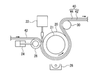
- An article having a fine concavo-convex structure on its surface is manufactured as follows using, for example, a manufacturing apparatus shown in FIG. Active energy ray curable from the tank 22 between the roll-shaped mold 20 having a fine concavo-convex structure (not shown) on the surface and a strip-shaped film 42 (transparent substrate) moving along the surface of the roll-shaped mold 20. A resin composition is supplied.
- the film 42 and the active energy ray curable resin composition are nipped between the roll-shaped mold 20 and the nip roll 26 whose nip pressure is adjusted by the pneumatic cylinder 24, and the active energy ray curable resin composition is niped with the film 42. And the roll-shaped mold 20 are uniformly distributed, and at the same time, the concave portions of the fine concavo-convex structure of the roll-shaped mold 20 are filled.
- the active energy ray curable resin composition By irradiating the active energy ray curable resin composition through the film 42 from the active energy ray irradiating device 28 installed below the roll-shaped mold 20, the active energy ray curable resin composition is cured. Then, the cured resin layer 44 to which the fine uneven structure on the surface of the roll-shaped mold 20 is transferred is formed. By peeling the film 42 having the cured resin layer 44 formed on the surface from the roll-shaped mold 20 with the peeling roll 30, an article 40 as shown in FIG. 3 is obtained.
- the active energy ray irradiation device 28 a high-pressure mercury lamp, a metal halide lamp or the like is preferable.
- the amount of light irradiation energy is preferably 100 to 10,000 mJ / cm 2 .
- the film 42 is a light transmissive film.
- the film material include acrylic resin, polycarbonate, styrene resin, polyester, cellulose resin (such as triacetyl cellulose), polyolefin, and alicyclic polyolefin.
- the cured resin layer 44 is a film made of a cured product of an active energy ray-curable resin composition described later, and has a fine uneven structure on the surface.
- the fine uneven structure on the surface of the article 40 is formed by transferring the fine uneven structure on the surface of the anodized alumina, and the active energy ray-curable resin composition is cured. It has the some convex part 46 which consists of a thing.
- the fine concavo-convex structure is preferably a so-called moth-eye structure in which a plurality of protrusions (convex portions) having a substantially conical shape or a pyramid shape are arranged. It is known that the moth-eye structure in which the distance between the protrusions is less than or equal to the wavelength of visible light is an effective anti-reflection measure by continuously increasing the refractive index from the refractive index of air to the refractive index of the material. It has been.
- the average interval between the convex portions is preferably not more than the wavelength of visible light, that is, not more than 400 nm.
- the average distance between the convex portions is about 100 nm, so that it is more preferably 200 nm or less, and particularly preferably 150 nm or less.
- the average interval between the convex portions is preferably 20 nm or more from the viewpoint of easy formation of the convex portions.
- the average interval between the convex portions is obtained by measuring 50 intervals between adjacent convex portions (distance from the center of the convex portion to the center of the adjacent convex portion) by electron microscope observation, and averaging these values. .
- the height of the protrusions is preferably 80 to 500 nm, more preferably 120 to 400 nm, and particularly preferably 150 to 300 nm when the average interval is 100 nm. If the height of the convex portion is 80 nm or more, the reflectance is sufficiently low and the wavelength dependency of the reflectance is small. If the height of a convex part is 500 nm or less, the scratch resistance of a convex part will become favorable.
- the height of the convex portion is a value obtained by measuring the distance between the topmost portion of the convex portion and the bottommost portion of the concave portion existing between the convex portions when observed with an electron microscope at a magnification of 30000 times.
- the aspect ratio of the protrusions is preferably 0.5 to 5.0, more preferably 0.8 to 4.5, and 1.2 to 4.0. Particularly preferred. If the aspect ratio of the convex portion is 0.5 or more, it can be sufficiently used as a superhydrophilic film or a superhydrophobic film. If the aspect ratio of the convex portion is 5.0 or less, the scratch resistance of the convex portion is good.
- the shape of the convex part is a shape in which the convex sectional area in the direction perpendicular to the height direction continuously increases in the depth direction from the outermost surface, that is, the sectional shape in the height direction of the convex part is a triangle, trapezoid, A shape such as a bell shape is preferred.
- the difference between the refractive index of the cured resin layer 44 and the refractive index of the film 42 is preferably 0.2 or less, more preferably 0.1 or less, and particularly preferably 0.05 or less.
- the refractive index difference is 0.2 or less, reflection at the interface between the cured resin layer 44 and the film 42 is suppressed.
- the water contact angle on the surface of the fine uneven structure is preferably 90 ° or more, more preferably 110 ° or more, and particularly preferably 120 ° or more. If the water contact angle is 90 ° or more, water stains are less likely to adhere, so that sufficient antifouling properties are exhibited. Moreover, since water does not adhere easily, anti-icing can be expected.
- the water contact angle on the surface of the fine uneven structure is preferably 25 ° or less, more preferably 23 ° or less, and particularly preferably 21 ° or less. If the water contact angle is 25 ° or less, the dirt attached to the surface is washed away with water, and oil dirt is less likely to adhere, so that sufficient antifouling properties are exhibited.
- the water contact angle is preferably 3 ° or more from the viewpoint of suppressing the deformation of the fine uneven structure due to water absorption of the cured resin layer 44 and the accompanying increase in reflectance.
- the active energy ray-curable resin composition contains a polymerizable compound and a polymerization initiator.
- the polymerizable compound include monomers, oligomers, and reactive polymers having a radical polymerizable bond and / or a cationic polymerizable bond in the molecule.
- Examples of the monomer having a radical polymerizable bond include a monofunctional monomer and a polyfunctional monomer.
- Monofunctional monomers include methyl (meth) acrylate, ethyl (meth) acrylate, propyl (meth) acrylate, n-butyl (meth) acrylate, i-butyl (meth) acrylate, s-butyl (meth) acrylate, t- Butyl (meth) acrylate, 2-ethylhexyl (meth) acrylate, lauryl (meth) acrylate, alkyl (meth) acrylate, tridecyl (meth) acrylate, stearyl (meth) acrylate, cyclohexyl (meth) acrylate, benzyl (meth) acrylate, Phenoxyethyl (meth) acrylate, isobornyl (meth) acrylate, glycidyl (meth
- Polyfunctional monomers include ethylene glycol di (meth) acrylate, tripropylene glycol di (meth) acrylate, isocyanuric acid ethylene oxide modified di (meth) acrylate, triethylene glycol di (meth) acrylate, diethylene glycol di (meth) acrylate , Neopentyl glycol di (meth) acrylate, 1,6-hexanediol di (meth) acrylate, 1,5-pentanediol di (meth) acrylate, 1,3-butylene glycol di (meth) acrylate, polybutylene glycol di (Meth) acrylate, 2,2-bis (4- (meth) acryloxypolyethoxyphenyl) propane, 2,2-bis (4- (meth) acryloxyethoxyphenyl) propane, 2,2-bis (4- (3- (Meth) acryloxy-2-hydroxypropoxy) phenyl) propane, 1,2-bis (3- (meth) acryloxy-2-hydroxypropoxy
- Examples of the monomer having a cationic polymerizable bond include monomers having an epoxy group, an oxetanyl group, an oxazolyl group, a vinyloxy group, and the like, and a monomer having an epoxy group is particularly preferable.
- oligomer or reactive polymer examples include unsaturated polyesters such as a condensate of unsaturated dicarboxylic acid and polyhydric alcohol; polyester (meth) acrylate, polyether (meth) acrylate, polyol (meth) acrylate, epoxy (meth) Examples thereof include acrylates, urethane (meth) acrylates, cationic polymerization type epoxy compounds, homopolymers of the above-described monomers having a radical polymerizable bond in the side chain, and copolymerized polymers.
- unsaturated polyesters such as a condensate of unsaturated dicarboxylic acid and polyhydric alcohol
- examples of the photopolymerization initiator include benzoin, benzoin methyl ether, benzoin ethyl ether, benzoin isopropyl ether, benzoin isobutyl ether, benzyl, benzophenone, p-methoxybenzophenone, 2,2-diethoxy.
- examples of the polymerization initiator include benzophenone, 4,4-bis (diethylamino) benzophenone, 2,4,6-trimethylbenzophenone, methyl orthobenzoylbenzoate, 4-phenylbenzophenone, t- Thioxanthones such as butylanthraquinone, 2-ethylanthraquinone, 2,4-diethylthioxanthone, isopropylthioxanthone, 2,4-dichlorothioxanthone; diethoxyacetophenone, 2-hydroxy-2-methyl-1-phenylpropan-1-one, benzyl Dimethyl ketal, 1-hydroxycyclohexyl-phenyl ketone, 2-methyl-2-morpholino (4-thiomethylphenyl) propan-1-one, 2-benzyl-2-dimethylamino-1- (4-morpho Benzophene ether such as benzoin methyl ether, benzo
- thermal polymerization initiator examples include methyl ethyl ketone peroxide, benzoyl peroxide, dicumyl peroxide, t-butyl hydroperoxide, cumene hydroperoxide, t-butyl peroxy octoate, organic peroxides such as t-butylperoxybenzoate and lauroyl peroxide; azo compounds such as azobisisobutyronitrile; N, N-dimethylaniline, N, N-dimethyl-p- Examples thereof include a redox polymerization initiator combined with an amine such as toluidine.
- the amount of the polymerization initiator is preferably 0.1 to 10 parts by mass with respect to 100 parts by mass of the polymerizable compound. When the amount of the polymerization initiator is less than 0.1 parts by mass, the polymerization is difficult to proceed. When the amount of the polymerization initiator exceeds 10 parts by mass, the cured film may be colored or the mechanical strength may be lowered.
- the active energy ray-curable resin composition may be a non-reactive polymer, an active energy ray sol-gel reactive composition, an antistatic agent, an additive such as a fluorine compound for improving antifouling properties, or a fine particle, if necessary.
- a small amount of a solvent may be contained.
- non-reactive polymers examples include acrylic resins, styrene resins, polyurethanes, cellulose resins, polyvinyl butyral, polyesters, thermoplastic elastomers, and the like.
- active energy ray sol-gel reactive composition examples include alkoxysilane compounds and alkyl silicate compounds.
- alkoxysilane compound examples include tetramethoxysilane, tetra-i-propoxysilane, tetra-n-propoxysilane, tetra-n-butoxysilane, tetra-sec-butoxysilane, tetra-t-butoxysilane, methyltriethoxysilane, Examples include methyltripropoxysilane, methyltributoxysilane, dimethyldimethoxysilane, dimethyldiethoxysilane, trimethylethoxysilane, trimethylmethoxysilane, trimethylpropoxysilane, and trimethylbutoxysilane.
- alkyl silicate compound examples include methyl silicate, ethyl silicate, isopropyl silicate, n-propyl silicate, n-butyl silicate, n-pentyl silicate, acetyl silicate and the like.
- the active energy ray-curable resin composition capable of forming a hydrophobic material includes a fluorine-containing compound or a silicone-based compound. It is preferable to use a composition.
- Fluorine-containing compounds examples include a fluorine-containing monomer, a fluorine-containing silane coupling agent, a fluorine-containing surfactant, and a fluorine-containing polymer.
- fluorine-containing monomer examples include a fluoroalkyl group-substituted vinyl monomer and a fluoroalkyl group-substituted ring-opening polymerizable monomer.
- fluoroalkyl group-substituted vinyl monomer examples include fluoroalkyl group-substituted (meth) acrylates, fluoroalkyl group-substituted (meth) acrylamides, fluoroalkyl group-substituted vinyl ethers, and fluoroalkyl group-substituted styrenes.
- fluoroalkyl group-substituted ring-opening polymerizable monomer examples include fluoroalkyl group-substituted epoxy compounds, fluoroalkyl group-substituted oxetane compounds, and fluoroalkyl group-substituted oxazoline compounds.
- Fluorine-containing silane coupling agents include 3,3,3-trifluoropropyltrimethoxysilane, 3,3,3-trifluoropropyltriacetoxysilane, dimethyl-3,3,3-trifluoropropylmethoxysilane, Examples include decafluoro-1,1,2,2-tetrahydrooctyltriethoxysilane.
- fluorine-containing surfactant examples include a fluoroalkyl group-containing anionic surfactant and a fluoroalkyl group-containing cationic surfactant.
- Fluorine-containing polymers include polymers of fluoroalkyl group-containing monomers, copolymers of fluoroalkyl group-containing monomers and poly (oxyalkylene) group-containing monomers, and copolymers of fluoroalkyl group-containing monomers and crosslinking reactive group-containing monomers. A polymer etc. are mentioned.
- the fluorine-containing polymer may be a copolymer with another copolymerizable monomer.
- Silicone compounds examples include (meth) acrylic acid-modified silicone, silicone resin, silicone silane coupling agent and the like.
- examples of the (meth) acrylic acid-modified silicone include silicone (di) (meth) acrylate, and examples thereof include silicone diacrylates “x-22-164” and “x-22-1602” manufactured by Shin-Etsu Chemical Co., Ltd. Preferably used.
- an active energy ray-curable resin composition capable of forming a hydrophilic material is a composition containing at least a hydrophilic monomer. It is preferable to use it. From the viewpoint of scratch resistance and imparting water resistance, those containing a cross-linkable polyfunctional monomer are more preferable. In addition, the same (namely, hydrophilic polyfunctional monomer) may be sufficient as the polyfunctional monomer which can be bridge
- the active energy ray-curable resin composition capable of forming a hydrophilic material includes a tetrafunctional or higher polyfunctional (meth) acrylate, a bifunctional or higher hydrophilic (meth) acrylate, and a monofunctional monomer as necessary. More preferably, the composition is used.
- tetrafunctional or higher polyfunctional (meth) acrylates examples include ditrimethylolpropane tetra (meth) acrylate, pentaerythritol tetra (meth) acrylate, pentaerythritol ethoxytetra (meth) acrylate, dipentaerythritol hydroxypenta (meth) acrylate, di Pentaerythritol hexa (meth) acrylate, succinic acid / trimethylolethane / acrylic acid molar mixture 1: 2: 4 condensation reaction mixture, urethane acrylates (manufactured by Daicel-Cytec: EBECRYL220, EBECRYL1290K, EBECRYL1290K, EBECRYL5129, EBECRYL8210, EBECRYL 8301, KRM 8200), polyether acrylates (manufactured by Daicel-Cytec:
- the ratio of the tetrafunctional or higher polyfunctional (meth) acrylate is preferably 10 to 90% by mass, more preferably 20 to 90% by mass, and particularly preferably 30 to 90% by mass. If the ratio of the tetrafunctional or higher polyfunctional (meth) acrylate is 10% by mass or more, the elastic modulus is increased and the scratch resistance is improved. If the ratio of the tetrafunctional or higher polyfunctional (meth) acrylate is 90% by mass or less, small cracks are hardly formed on the surface, and the appearance is difficult to occur.
- Long-chain polyethylene such as Aronix M-240, Aronix M260 (manufactured by Toagosei Co., Ltd.), NK ester AT-20E, NK ester ATM-35E (manufactured by Shin-Nakamura Chemical Co., Ltd.)
- polyfunctional acrylates having glycol and polyethylene glycol dimethacrylate. These may be used alone or in combination of two or more.
- polyethylene glycol dimethacrylate the total of the average repeating units of polyethylene glycol chains present in one molecule is preferably 6 to 40, more preferably 9 to 30, and particularly preferably 12 to 20.
- the average repeating unit of the polyethylene glycol chain is 6 or more, the hydrophilicity is sufficient and the antifouling property is improved.
- the average repeating unit of the polyethylene glycol chain is 40 or less, the compatibility with a polyfunctional (meth) acrylate having 4 or more functionalities is improved, and the active energy ray-curable resin composition is hardly separated.
- the proportion of the bifunctional or higher functional (meth) acrylate is preferably 3 to 90% by mass, more preferably 3 to 70% by mass.
- the ratio of the bifunctional or higher hydrophilic (meth) acrylate is 3% by mass or more, the hydrophilicity is sufficient and the antifouling property is improved.
- the ratio of the bifunctional or higher hydrophilic (meth) acrylate is 90% by mass or less, the elastic modulus is increased and the scratch resistance is improved.
- hydrophilic monofunctional monomers examples include monofunctional (meth) acrylates having a polyethylene glycol chain in the ester group such as M-20G, M-90G, and M-230G (manufactured by Shin-Nakamura Chemical Co., Ltd.), hydroxyalkyl (meth) acrylates, etc. And cationic monomers such as monofunctional (meth) acrylates having a hydroxyl group in the ester group, monofunctional acrylamides, methacrylamidopropyltrimethylammonium methyl sulfate, and methacryloyloxyethyltrimethylammonium methyl sulfate.
- a viscosity modifier such as acryloylmorpholine or vinylpyrrolidone
- an adhesion improver such as acryloyl isocyanate for improving the adhesion to the article body, or the like may be used.
- the proportion of the monofunctional monomer is preferably 0 to 20% by mass, and more preferably 5 to 15% by mass.
- the proportion of the monofunctional monomer is 20% by mass or less, antifouling property or scratch resistance is sufficient without a shortage of tetrafunctional or higher polyfunctional (meth) acrylate or bifunctional or higher hydrophilic (meth) acrylate.
- the monofunctional monomer may be blended in an active energy ray-curable resin composition in an amount of 0 to 35 parts by mass as a low-polymerization polymer obtained by (co) polymerizing one or more types.
- a polymer having a low degree of polymerization 40/60 of monofunctional (meth) acrylates having a polyethylene glycol chain in an ester group such as M-230G (manufactured by Shin-Nakamura Chemical Co., Ltd.) and methacrylamide propyltrimethylammonium methyl sulfate.
- Copolymer oligomer (MRC Unitech Co., Ltd., MG polymer) and the like can be mentioned.
- Applications of the article 40 include antireflection articles, antifogging articles, antifouling articles, water repellent articles, and more specifically, antireflection for displays, automobile meter covers, automobile mirrors, automobile windows, organic or inorganic electro Examples thereof include a member for improving light extraction efficiency of luminescence, a solar cell member, and the like.
- the fine concavo-convex structure on the surface of the mold of the present invention is transferred to the surface of the transparent substrate, so that the haze is low.
- An article having a high visible light transmittance can be produced.
- an optical film in which streak defects such as white streaks occur is used in an electronic display device such as a liquid crystal, moire and the like due to the interaction with the structure pitch of other optical films and the pixel pitch of the liquid crystal display panel. Interference spots called may occur.
- the optical film manufactured using the mold based on the present invention suppresses the generation of white streaks, it is possible to suppress the occurrence of moire when used in an electronic display device.
- the article having the fine concavo-convex structure on the surface is not limited to the article 40 in the illustrated example.
- the fine concavo-convex structure may be directly formed on the surface of the film 42 by the thermal imprint method without providing the cured resin layer 44.
- the fine uneven structure is formed on the surface of the cured resin layer 44 from the viewpoint that the fine uneven structure can be efficiently formed using the roll-shaped mold 20.
- Total light transmittance, haze The total light transmittance and haze of the article were measured using a haze meter (manufactured by Suga Test Instruments Co., Ltd.) in accordance with JIS K7361-1.
- composition of active energy ray-curable composition A 45 parts by weight of a condensation reaction mixture of succinic acid / trimethylolethane / acrylic acid molar ratio 1: 2: 4, 45 parts by mass of 1,6-hexanediol diacrylate (produced by Osaka Organic Chemical Co., Ltd.) 10 parts by mass of radical polymerizable silicone oil (X-22-1602, manufactured by Shin-Etsu Chemical Co., Ltd.) 3 parts by mass of 1-hydroxycyclohexyl phenyl ketone (Irgacure 184, manufactured by Ciba Specialty Chemicals).
- composition of active energy ray-curable composition B 65 parts by weight of a condensation reaction mixture of succinic acid / trimethylolethane / acrylic acid molar ratio 1: 2: 4, 35 parts by mass of polyethylene glycol diacrylate (Aronix M260, manufactured by Toagosei Co., Ltd.) 3 parts by mass of 1-hydroxycyclohexyl phenyl ketone (Irgacure 184, manufactured by Ciba Specialty Chemicals).
- composition of active energy ray-curable composition C 65 parts by weight of a condensation reaction mixture of succinic acid / trimethylolethane / acrylic acid molar ratio 1: 2: 4, 25 parts by mass of 1,6-hexanediol diacrylate (produced by Osaka Organic Chemical Co., Ltd.) 10 parts by mass of radical polymerizable silicone oil (X-22-1602, manufactured by Shin-Etsu Chemical Co., Ltd.) 3 parts by mass of 1-hydroxycyclohexyl phenyl ketone (Irgacure 184, manufactured by Ciba Specialty Chemicals).
- Example 1 An aluminum ingot having a purity of 99.99% is cut into a cylindrical shape having an outer diameter of 200 mm, an inner diameter of 155 mm, and a length of 350 mm, and the surface is processed so that the arithmetic average roughness Ra of the work surface is 0.03 ⁇ m or less. Mirror surface cutting was performed to obtain a cylindrical aluminum substrate. The 60 ° glossiness of this surface was measured and found to be 896%.
- the roll mold was immersed in a 0.1% by mass solution of a mold release agent (manufactured by Daikin Industries, Ltd., OPTOOL DSX) for 10 minutes, and air-dried for 24 hours to perform the mold release agent treatment.
- a mold release agent manufactured by Daikin Industries, Ltd., OPTOOL DSX
- the 60 ° glossiness of this surface was measured and found to be 808%.
- Example 2 An aluminum ingot with a purity of 99.97% is cut into a cylindrical shape having an outer diameter of 200 mm, an inner diameter of 155 mm, and a length of 350 mm, and the surface is processed so that the arithmetic average roughness Ra of the work surface is 0.02 ⁇ m or less. Mirror surface cutting was performed to obtain a cylindrical aluminum substrate. The 60 ° glossiness of this surface was measured and found to be 899%.
- the roll mold was immersed in a 0.1% by mass solution of a mold release agent (manufactured by Daikin Industries, Ltd., OPTOOL DSX) for 10 minutes, and air-dried for 24 hours to perform the mold release agent treatment.
- a mold release agent manufactured by Daikin Industries, Ltd., OPTOOL DSX
- the 60 ° glossiness of this surface was measured and found to be 819%.
- Example 3 A roll mold was obtained in the same manner as in Example 2 except that the temperature in the step (b) was 23 ° C. The results are shown in Table 1.
- Example 4 A roll-shaped mold was obtained in the same manner as in Example 1 except that a chromic acid-phosphoric acid mixed solution (an aqueous solution containing 8% by mass of phosphoric acid and 1.1% by mass of chromic acid) was used in step (b). It was. The results are shown in Table 1.
- Example 5 A roll-shaped mold was obtained in the same manner as in Example 1, except that a chromic acid-phosphoric acid mixed solution (an aqueous solution containing 4% by mass phosphoric acid and 2.3% by mass chromic acid) was used in the step (b). It was. The results are shown in Table 1.
- Example 6 In the step (b), except that a chromic acid-phosphoric acid mixed solution (an aqueous solution containing 5% by mass phosphoric acid and 1.5% by mass chromic acid) was used, the temperature was 65 ° C., and the immersion time was 1 hour.
- a roll-shaped mold was obtained in the same manner as in Example 2. The results are shown in Table 1.
- Example 7 In the step (b), except that a chromic acid-phosphoric acid mixed solution (an aqueous solution containing 9% by mass of phosphoric acid and 2.0% by mass of chromic acid) was used, the temperature was 15 ° C., and the immersion time was 8 hours. A roll-shaped mold was obtained in the same manner as in Example 1. The results are shown in Table 1.
- Example 1 A roll-shaped mold was obtained in the same manner as in Example 1 except that the temperature in step (b) was 70 ° C. The results are shown in Table 1.
- Example 2 A roll mold was obtained in the same manner as in Example 2 except that the temperature in the step (b) was set to 70 ° C. The results are shown in Table 1.
- Example 3 A roll mold was obtained in the same manner as in Example 2 except that the temperature in the step (b) was 5 ° C. and the immersion time was 0.5 hours. The results are shown in Table 1.
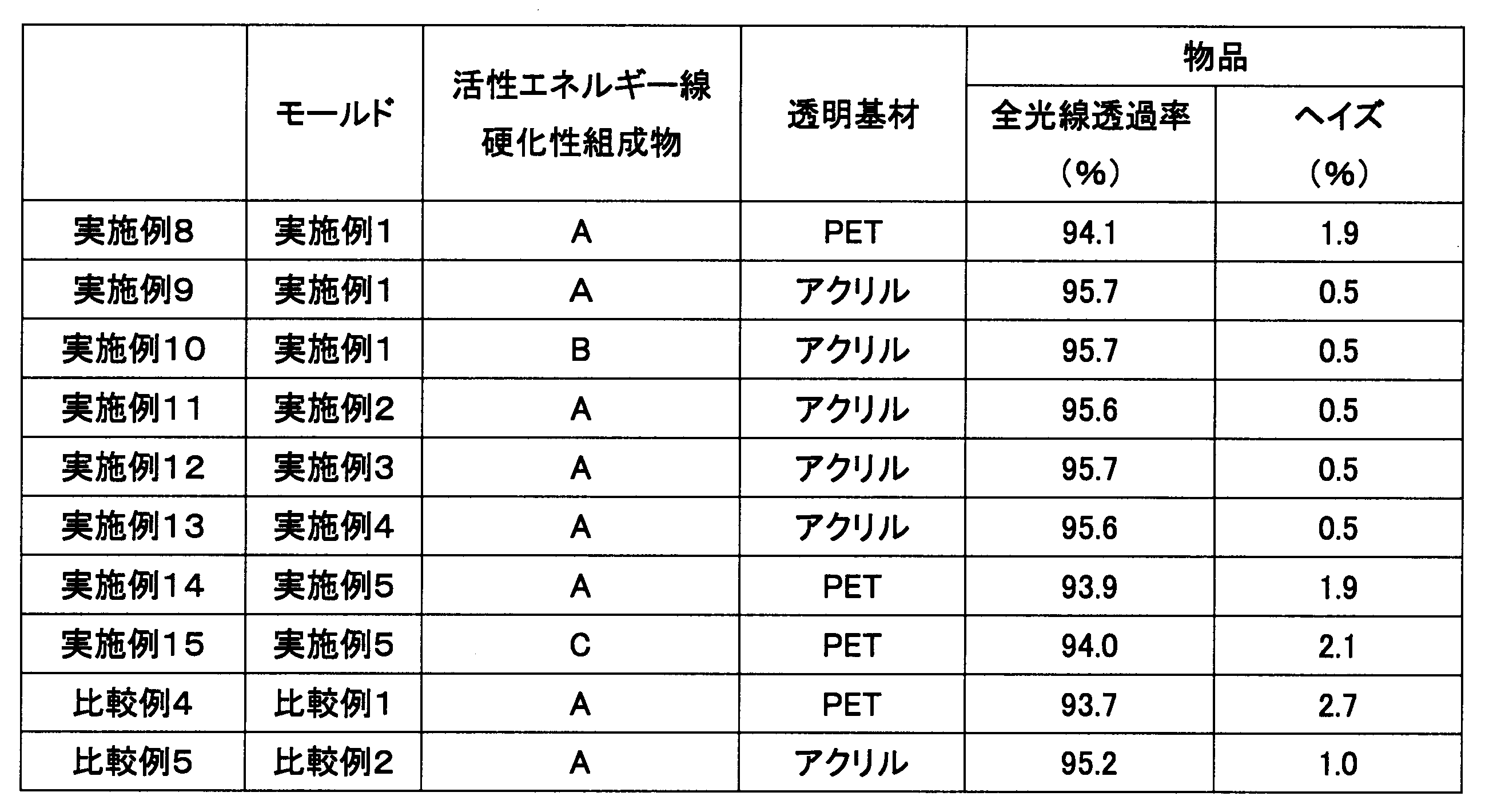
- Example 8 The roll-shaped mold obtained in Example 1 was installed in the manufacturing apparatus shown in FIG. 2, and an article was manufactured as follows. As shown in FIG. 2, the roll-shaped mold 20 was fitted into a shaft 21 made of carbon steel for mechanical structure provided with a flow path for cooling water. Next, a film 42 (polyethylene terephthalate (PET) film, manufactured by Toyobo Co., Ltd.) that is nipped between the nip roll 26 and the roll-shaped mold 20 through a nozzle for supplying the active energy ray-curable composition A from the tank 22 at room temperature. A4300).
- PET polyethylene terephthalate
- the nipping was performed by the nip roll 26 in which the nip pressure was adjusted by the pneumatic cylinder 24, and the active energy ray-curable composition A was also filled in the pores (recesses) of the roll-shaped mold 20.
- the active energy beam irradiating device 28 (with the active energy beam-curable composition A sandwiched between the roll-shaped mold 20 and the film 42 ( The active energy ray-curable composition A was cured by irradiating ultraviolet rays from a 240 W / cm ultraviolet irradiation device) to form the cured resin layer 44, and then the cured resin layer 44 was formed on the surface by the peeling roll 30.
- the film 42 was peeled from the roll mold 20 to obtain an article 40 having a fine concavo-convex structure on the surface. The results are shown in Table 2.
- Example 9 An article having a fine concavo-convex structure on the surface was obtained in the same manner as in Example 6 except that an acrylic film (manufactured by Mitsubishi Rayon Co., Ltd., HBK-002) was used as the film 42. The results are shown in Table 2.
- Example 10 An article having a fine relief structure on the surface was obtained in the same manner as in Example 7 except that the active energy ray-curable composition B was used. The results are shown in Table 2.
- Example 11 An article having a fine concavo-convex structure on the surface was obtained in the same manner as in Example 7 except that the roll-shaped mold obtained in Example 2 was used. The results are shown in Table 2.
- Example 12 An article having a fine concavo-convex structure on the surface was obtained in the same manner as in Example 7 except that the roll-shaped mold obtained in Example 3 was used. The results are shown in Table 2.
- Example 13 An article having a fine concavo-convex structure on its surface was obtained in the same manner as in Example 7 except that the roll-shaped mold obtained in Example 4 was used. The results are shown in Table 2.
- Example 14 An article having a fine concavo-convex structure on the surface was obtained in the same manner as in Example 6 except that the roll-shaped mold obtained in Example 5 was used. The results are shown in Table 2.
- Example 15 An article having a fine relief structure on the surface was obtained in the same manner as in Example 12 except that the active energy ray-curable composition C was used. The results are shown in Table 2.
- the present invention is useful for efficient mass production of antireflection articles, antifogging articles, antifouling articles, and water repellent articles.
Landscapes
- Engineering & Computer Science (AREA)
- Chemical & Material Sciences (AREA)
- Physics & Mathematics (AREA)
- Manufacturing & Machinery (AREA)
- Mechanical Engineering (AREA)
- Electrochemistry (AREA)
- Metallurgy (AREA)
- Organic Chemistry (AREA)
- Materials Engineering (AREA)
- Chemical Kinetics & Catalysis (AREA)
- General Physics & Mathematics (AREA)
- Optics & Photonics (AREA)
- Ophthalmology & Optometry (AREA)
- Health & Medical Sciences (AREA)
- Microelectronics & Electronic Packaging (AREA)
- General Chemical & Material Sciences (AREA)
- Computer Hardware Design (AREA)
- Shaping Of Tube Ends By Bending Or Straightening (AREA)
- Surface Treatment Of Optical Elements (AREA)
- Moulds For Moulding Plastics Or The Like (AREA)
Abstract
Description
また、該モールドとしては、簡便に製造できることから、複数の細孔を有する陽極酸化アルミナをアルミニウム基材の表面に有するモールドが注目されている(特許文献1)。
また、陽極酸化により微細な凹凸構造を形成する際に、表面光沢度が所定の値以上のアルミニウム基材を用いることが、特許文献2に記載されている。
(a)切削加工された高純度のアルミニウム基材を電解液中で陽極酸化してアルミニウム基材の表面に酸化皮膜を形成する工程。
(b)工程(a)の後、アルミニウム基材をクロム酸-リン酸混液に浸漬して酸化皮膜を除去する工程。
(c)工程(b)の後、アルミニウム基材を電解液中で再度陽極酸化して細孔を有する酸化皮膜を形成する工程。
(d)工程(c)の後、アルミニウム基材を、酸化皮膜を溶解する溶液に浸漬して細孔の径を拡大させる工程。
(e)工程(d)の後、アルミニウム基材を電解液中で再度陽極酸化する工程。
(f)工程(d)と工程(e)を繰り返し行い、直径が開口部から深さ方向に連続的に減少する形状(以下、テーパー状と記す場合がある。)の複数の細孔を有する陽極酸化アルミナがアルミニウム基材の表面に形成されたモールドを得る工程。
白筋のある状態でモールドの微細凹凸構造を透明基材の表面に転写した場合、白筋も透明基材の表面に転写される。白筋は、光を散乱しているため白く見えているのであり、それが表面に転写された物品は、ヘイズが高くなり、結果、可視光透過率が低下する。
ヘイズが低く、可視光透過率が高い物品(反射防止物品等)を得るためには、モールドの微細凹凸構造が形成された側の表面に白筋の発生がないか、または目視できない、すなわち表面の鏡面性(光沢度)の高いモールドが必要である。
すなわち、本発明のモールドは、純度99.5質量%以上のアルミニウム基材の表面を陽極酸化して該表面に微細凹凸構造が形成されたモールドであって、微細凹凸構造が形成された側の表面の60度光沢度が、750%以上であることを特徴とする。
本発明のモールドの製造方法によれば、ヘイズが低く、可視光透過率が高い、微細凹凸構造を表面に有する物品を得ることができるモールドを製造できる。
本発明の、微細凹凸構造を表面に有する物品の製造方法によれば、ヘイズが低く、可視光透過率が高い物品を製造できる。
本発明のモールドは、純度99.5質量%以上のアルミニウム基材の表面を陽極酸化することによって、微細凹凸構造が形成されたモールドである。微細凹凸構造は、通常、直径が開口部から深さ方向に連続的に減少する形状の複数の細孔からなる。
アルミニウム基材の形状としては、ロール状、円管状、平板状、シート状等が挙げられる。
アルミニウムの純度は、99.5質量%以上であり、99.8質量%以上が好ましく、99.9質量%以上がより好ましい。アルミニウムの純度が低いと、陽極酸化した時に、不純物の偏析により可視光を散乱する大きさの凹凸構造が形成されたり、陽極酸化で得られる細孔の規則性が低下したりすることがある。
本発明のモールドの、微細凹凸構造が形成された側の表面の60度光沢度は、750%以上であり、780%以上が好ましい。60度光沢度が750%以上であれば、モールドの微細凹凸構造が形成された側の表面に白筋の発生がないか、または目視できない状態であり、モールドの微細凹凸構造を透明基材の表面に転写して得られた物品は、ヘイズが低く、可視光透過率が高い。
60度光沢度は、JIS Z8741に準拠した光沢計を用いて測定される。また、白筋の有無による光沢度の差が顕著に現れることから、光沢度の測定角は60度とする。
以上説明した本発明のモールドにあっては、微細凹凸構造が形成された側の表面の60度光沢度が750%以上であるため、モールドの微細凹凸構造を透明基材の表面に転写して得られた物品の表面における光の散乱が少ない。そのため、ヘイズが低く、可視光透過率が高い、微細凹凸構造を表面に有する物品を得ることができる。
本発明のモールドは、下記の工程(a)~(f)を有する方法で製造される。
(a)切削加工された、純度99.5質量%以上のアルミニウム基材を電解液中で陽極酸化してアルミニウム基材の表面に酸化皮膜を形成する工程。
(b)工程(a)の後、アルミニウム基材をクロム酸-リン酸混液に浸漬して酸化皮膜を除去する工程。
(c)工程(b)の後、アルミニウム基材を電解液中で再度陽極酸化して細孔を有する酸化皮膜を形成する工程。
(d)工程(c)の後、アルミニウム基材を、酸化皮膜を溶解する溶液に浸漬して細孔の径を拡大させる工程。
(e)工程(d)の後、アルミニウム基材を電解液中で再度陽極酸化する工程。
(f)工程(d)と工程(e)を繰り返し行い、複数の細孔を有する陽極酸化アルミナがアルミニウム基材の表面に形成されたモールドを得る工程。
図1に示すように、切削加工されたアルミニウム基材10を定電圧下、電解液中で陽極酸化すると、細孔12を有する酸化皮膜14が形成される。
アルミニウム基材の形状としては、ロール状、円管状、平板状、シート状等が挙げられる。
また、アルミニウム基材は、表面状態を平滑化にするために、機械研磨、羽布研磨、化学的研磨、電解研磨処理(エッチング処理)等で研磨されることが好ましい。また、アルミニウム基材は、所定の形状に切削加工する際に用いた油が付着していることがあるため、陽極酸化の前にあらかじめ脱脂処理されることが好ましい。
電解液としては、硫酸、シュウ酸、リン酸等が挙げられる。
シュウ酸の濃度は、0.7M以下が好ましい。シュウ酸の濃度が0.7Mを超えると、電流値が高くなりすぎて酸化皮膜の表面が粗くなることがある。
化成電圧が30~60Vの時、間隔が100nmの規則性の高い細孔を有する陽極酸化アルミナを得ることができる。化成電圧がこの範囲より高くても低くても規則性が低下する傾向にある。
電解液の温度は、60℃以下が好ましく、45℃以下がより好ましい。電解液の温度が60℃を超えると、いわゆる「ヤケ」といわれる現象がおこり、細孔が壊れたり、表面が溶けて細孔の規則性が乱れたりすることがある。
硫酸の濃度は0.7M以下が好ましい。硫酸の濃度が0.7Mを超えると、電流値が高くなりすぎて定電圧を維持できなくなることがある。
化成電圧が25~30Vの時、間隔が63nmの規則性の高い細孔を有する陽極酸化アルミナを得ることができる。化成電圧がこの範囲より高くても低くても規則性が低下する傾向がある。
電解液の温度は、30℃以下が好ましく、20℃以下がより好ましい。電解液の温度が30℃を超えると、いわゆる「ヤケ」といわれる現象がおこり、細孔が壊れたり、表面が溶けて細孔の規則性が乱れたりすることがある。
図1に示すように、酸化皮膜14を一旦除去し、これを陽極酸化の細孔発生点16にすることで細孔の規則性を向上することができる。
クロム酸-リン酸混液中のクロム酸の濃度は、0.1~10質量%が好ましく、0.5~5.0%がより好ましく、1.0~2.5%が更に好ましい。また、クロム酸-リン酸混液中のリン酸の濃度は、0.1~20質量%が好ましく、1.0~10%がより好ましく、2.0~8.0%が更に好ましい。クロム酸およびリン酸の濃度が該範囲内であれば、白筋の発生を抑えつつ、酸化皮膜の除去を行うことができる。
図1に示すように、酸化皮膜を除去したアルミニウム基材10を再度陽極酸化すると、細孔発生点16に、円柱状の細孔12を有する酸化皮膜14が形成される。
陽極酸化は、工程(a)と同様な条件で行えばよい。陽極酸化の時間を長くするほど深い細孔を得ることができる。
図1に示すように、細孔12の径を拡大させる処理(以下、細孔径拡大処理と記す。)を行う。細孔径拡大処理は、酸化皮膜を溶解する溶液に浸漬して陽極酸化で得られた細孔の径を拡大させる処理である。このような溶液としては、例えば、5質量%程度のリン酸水溶液等が挙げられる。
細孔径拡大処理の時間を長くするほど、細孔径は大きくなる。
図1に示すように、再度陽極酸化すると、円柱状の細孔12の底部から下に延びる、直径の小さい円柱状の細孔12がさらに形成される。
陽極酸化は、工程(a)と同様な条件で行えばよい。陽極酸化の時間を長くするほど深い細孔を得ることができる。
図1に示すように、工程(d)の細孔径拡大処理と、工程(e)の陽極酸化を繰り返すと、テーパー状の細孔12を有する酸化皮膜14が形成され、アルミニウム基材10の表面に陽極酸化アルミナ(アルミニウムの多孔質の酸化皮膜(アルマイト))を有するモールド18が得られる。最後は工程(d)で終わることが好ましい。
細孔12間の平均間隔は、可視光の波長以下、すなわち400nm以下である。細孔12間の平均間隔は、20nm以上が好ましい。
細孔12間の平均間隔は、電子顕微鏡観察によって隣接する細孔12間の間隔(細孔12の中心から隣接する細孔12の中心までの距離)を50点測定し、これらの値を平均したものである。
細孔12の深さは、電子顕微鏡観察によって倍率30000倍で観察したときにおける、細孔12の最底部と、細孔12間に存在する凸部の最頂部との間の距離を測定した値である。
細孔12のアスペクト比(細孔の深さ/細孔間の平均間隔)は、0.5~5.0が好ましく、0.8~4.5がより好ましく、1.2~4.0が特に好ましい。
以上のような工程により得られた本発明のモールドは、表面の60度光沢度が750%以上となる。また、モールド上に白筋が発生することが抑制されているため、該モールドを用いてヘイズが低く、全光線透過率の高い物品を得ることができる。
離型剤としては、アルミニウム基材の陽極酸化アルミナと化学結合を形成し得る官能基を有するものが好ましい。
(1)離型剤の希釈溶液にモールド本体を浸漬する方法。
(2)離型剤またはその希釈溶液を、モールドの微細凹凸構造が形成された側の表面に塗布する方法。
(g)モールドを水洗する工程。
(h)工程(g)の後、モールドにエアーを吹き付け、モールドの表面に付着した水滴を除去する工程。
(i)加水分解性シリル基を有するフッ素化合物をフッ素系溶媒で希釈した希釈溶液に、モールドを浸漬する工程。
(j)浸漬したモールドをゆっくりと溶液から引き上げる工程。
(k)必要に応じて、工程(j)よりも後段にてモールドを加熱加湿させる工程。
(l)モールド本体を乾燥させる工程。
モールドには、微細凹凸構造を形成する際に用いた薬剤(細孔径拡大処理に用いたリン酸水溶液等)、不純物(埃等)等が付着しているため、水洗によってこれを除去する。
モールドの表面に水滴が付着していると、工程(i)の希釈溶液が劣化するため、モールドにエアーを吹き付け、目に見える水滴はほぼ除去する。
希釈用のフッ素系溶媒としては、ハイドロフルオロポリエーテル、パーフルオロヘキサン、パーフルオロメチルシクロヘキサン、パーフルオロ-1,3-ジメチルシクロヘキサン、ジクロロペンタフルオロプロパン等が挙げられる。
加水分解性シリル基を有するフッ素化合物の濃度は、希釈溶液(100質量%)中、0.01~0.5質量%が好ましい。
浸漬時間は、1~30分が好ましい。
浸漬温度は、0~50℃が好ましい。
浸漬したモールドを溶液から引き上げる際には、電動引き上げ機等を用いて、一定速度で引き上げ、引き上げ時の揺動を抑えることが好ましい。これにより塗布ムラを少なくできる。
引き上げ速度は、1~10mm/secが好ましい。
工程(j)よりも後段にて、モールドを加熱加湿させてもよい。モールドを加熱加湿下に放置することによって、フッ素化合物(離型剤)の加水分解性シリル基が加水分解されてシラノール基が生成し、該シラノール基とモールドの表面の水酸基との反応が十分に進行し、フッ素化合物の定着性が向上する。加湿方法としては、飽和塩水溶液を用いた飽和塩法、水を加熱して加湿する方法、加熱した水蒸気をモールドに直接吹付ける方法等が考えられる。この工程は恒温恒湿器中で行えばよい。
加熱温度は、30~150℃が好ましい。
加湿条件は、相対湿度60%以上が好ましい。
放置時間は、10分~7日が好ましい。
モールドを乾燥させる工程では、モールドを風乾させてもよく、乾燥機等で強制的に加熱乾燥させてもよい。
乾燥温度は、30~150℃が好ましい。
乾燥時間は、5~300分が好ましい。
以上説明した本発明のモールドの製造方法にあっては、工程(b)におけるクロム酸-リン酸混液の濃度、温度、浸漬時間を特定の範囲内としているため、白筋の発生を抑えることができる。そのため、モールドの微細凹凸構造を透明基材の表面に転写して得られた物品の表面における光の散乱が少なくなり、ヘイズが低く、可視光透過率が高い、微細凹凸構造を表面に有する物品を得ることができる。
本発明の、微細凹凸構造を表面に有する物品の製造方法は、本発明のモールドの表面の微細凹凸構造を、透明基材の表面に転写する方法である。具体的には、本発明のモールドと透明基材との間に活性エネルギー線硬化性樹脂組成物を充填し、これに活性エネルギー線を照射して硬化させて、モールドの微細凹凸構造が転写された硬化樹脂層を透明基材の表面に形成し、硬化樹脂層が表面に形成された透明基材をモールドから剥離する方法(いわゆる光インプリント法)が挙げられる。
基材の形状としては、フィルム、シート、射出成形品、プレス成形品等が挙げられる。
基材の材質としては、例えば、ポリカーボネート、ポリスチレン系樹脂、ポリエステル、アクリル系樹脂、セルロース系樹脂(トリアセチルセルロース等)、ポリオレフィン、ガラス等が挙げられる。
微細凹凸構造を表面に有する物品は、例えば、図2に示す製造装置を用いて、下記のようにして製造される。
表面に微細凹凸構造(図示略)を有するロール状モールド20と、ロール状モールド20の表面に沿って移動する帯状のフィルム42(透明基材)との間に、タンク22から活性エネルギー線硬化性樹脂組成物を供給する。
剥離ロール30により、表面に硬化樹脂層44が形成されたフィルム42をロール状モールド20から剥離することによって、図3に示すような物品40を得る。
陽極酸化アルミナのモールドを用いた場合の物品40の表面の微細凹凸構造は、陽極酸化アルミナの表面の微細凹凸構造を転写して形成されたものであり、活性エネルギー線硬化性樹脂組成物の硬化物からなる複数の凸部46を有する。
凸部間の平均間隔は、電子顕微鏡観察によって隣接する凸部間の間隔(凸部の中心から隣接する凸部の中心までの距離)を50点測定し、これらの値を平均したものである。
凸部の高さは、電子顕微鏡によって倍率30000倍で観察したときにおける、凸部の最頂部と、凸部間に存在する凹部の最底部との間の距離を測定した値である。
活性エネルギー線硬化性樹脂組成物は、重合性化合物および重合開始剤を含む。
重合性化合物としては、分子中にラジカル重合性結合および/またはカチオン重合性結合を有するモノマー、オリゴマー、反応性ポリマー等が挙げられる。
単官能モノマーとしては、メチル(メタ)アクリレート、エチル(メタ)アクリレート、プロピル(メタ)アクリレート、n-ブチル(メタ)アクリレート、i-ブチル(メタ)アクリレート、s-ブチル(メタ)アクリレート、t-ブチル(メタ)アクリレート、2-エチルヘキシル(メタ)アクリレート、ラウリル(メタ)アクリレート、アルキル(メタ)アクリレート、トリデシル(メタ)アクリレート、ステアリル(メタ)アクリレート、シクロヘキシル(メタ)アクリレート、ベンジル(メタ)アクリレート、フェノキシエチル(メタ)アクリレート、イソボルニル(メタ)アクリレート、グリシジル(メタ)アクリレート、テトラヒドロフルフリル(メタ)アクリレート、アリル(メタ)アクリレート、2-ヒドロキシエチル(メタ)アクリレート、ヒドロキシプロピル(メタ)アクリレート、2-メトキシエチル(メタ)アクリレート、2-エトキシエチル(メタ)アクリレート等の(メタ)アクリレート誘導体;(メタ)アクリル酸、(メタ)アクリロニトリル;スチレン、α-メチルスチレン等のスチレン誘導体;(メタ)アクリルアミド、N-ジメチル(メタ)アクリルアミド、N-ジエチル(メタ)アクリルアミド、ジメチルアミノプロピル(メタ)アクリルアミド等の(メタ)アクリルアミド誘導体等が挙げられる。これらは、1種を単独で用いてもよく、2種類以上を併用してもよい。
活性エネルギー線ゾルゲル反応性組成物としては、アルコキシシラン化合物、アルキルシリケート化合物等が挙げられる。
硬化樹脂層の微細凹凸構造の表面の水接触角を90°以上にするためには、疎水性の材料を形成し得る活性エネルギー線硬化性樹脂組成物として、フッ素含有化合物またはシリコーン系化合物を含む組成物を用いることが好ましい。
フッ素含有化合物としては、フッ素含有モノマー、フッ素含有シランカップリング剤、フッ素含有界面活性剤、フッ素含有ポリマー等が挙げられる。
フルオロアルキル基置換ビニルモノマーとしては、フルオロアルキル基置換(メタ)アクリレート、フルオロアルキル基置換(メタ)アクリルアミド、フルオロアルキル基置換ビニルエーテル、フルオロアルキル基置換スチレン等が挙げられる。
シリコーン系化合物としては、(メタ)アクリル酸変性シリコーン、シリコーン樹脂、シリコーン系シランカップリング剤等が挙げられる。
(メタ)アクリル酸変性シリコーンとしては、シリコーン(ジ)(メタ)アクリレート等が挙げられ、例えば、信越化学工業社製のシリコーンジアクリレート「x-22-164」「x-22-1602」等が好ましく用いられる。
硬化樹脂層の微細凹凸構造の表面の水接触角を25°以下にするためには、親水性の材料を形成し得る活性エネルギー線硬化性樹脂組成物として、少なくとも親水性モノマーを含む組成物を用いることが好ましい。また、耐擦傷性や耐水性付与の観点からは、架橋可能な多官能モノマーを含むものがより好ましい。なお、親水性モノマーと架橋可能な多官能モノマーは、同一(すなわち、親水性多官能モノマー)であってもよい。さらに、活性エネルギー線硬化性樹脂組成物は、その他のモノマーを含んでいてもよい。
4官能以上の多官能(メタ)アクリレートとしては、5官能以上の多官能(メタ)アクリレートがより好ましい。
ポリエチレングリコールジメタクリレートにおいて、一分子内に存在するポリエチレングリコール鎖の平均繰り返し単位の合計は、6~40が好ましく、9~30がより好ましく、12~20が特に好ましい。ポリエチレングリコール鎖の平均繰り返し単位が6以上であれば、親水性が十分となり、防汚性が向上する。ポリエチレングリコール鎖の平均繰り返し単位が40以下であれば、4官能以上の多官能(メタ)アクリレートとの相溶性が良好となり、活性エネルギー線硬化性樹脂組成物が分離しにくい。
親水性単官能モノマーとしては、M-20G、M-90G、M-230G(新中村化学社製)等のエステル基にポリエチレングリコール鎖を有する単官能(メタ)アクリレート、ヒドロキシアルキル(メタ)アクリレート等のエステル基に水酸基を有する単官能(メタ)アクリレート、単官能アクリルアミド類、メタクリルアミドプロピルトリメチルアンモニウムメチルサルフェート、メタクリロイルオキシエチルトリメチルアンモニウムメチルサルフェート等のカチオン性モノマー類等が挙げられる。
また、単官能モノマーとして、アクリロイルモルホリン、ビニルピロリドン等の粘度調整剤、物品本体への密着性を向上させるアクリロイルイソシアネート類等の密着性向上剤等を用いてもよい。
物品40の用途としては、反射防止物品、防曇性物品、防汚性物品、撥水性物品、より具体的には、ディスプレイ用反射防止、自動車メーターカバー、自動車ミラー、自動車窓、有機または無機エレクトロルミネッセンスの光取り出し効率向上部材、太陽電池部材等が挙げられる。
以上説明した本発明の、微細凹凸構造を表面に有する物品の製造方法にあっては、本発明のモールドの表面の微細凹凸構造を、透明基材の表面に転写しているため、ヘイズが低く、可視光透過率が高い物品を製造できる。また、白筋のような筋状の欠陥が発生した光学フィルムを液晶等の電子表示装置に用いると、その他の光学フィルムの構造ピッチや液晶表示パネルの画素ピッチ等との相互作用により、モアレと呼ばれる干渉斑が発生してしまうことがある。しかしながら、本願発明に基づくモールド用いて製造された光学フィルムは、白筋の発生が抑制されるために、電子表示装置に用いた際にモアレの発生を抑制することが可能となる。
陽極酸化アルミナの一部を削り、断面にプラチナを1分間蒸着し、電界放出形走査電子顕微鏡(日本電子社製、JSM-7400F)を用いて、加速電圧3.00kVの条件にて、断面を観察し、細孔の間隔、細孔の深さを測定した。各測定は、それぞれ50点について行い、平均値を求めた。
光沢計(コニカミノルタ社製、GM-268)を用いて60度光沢度を10回測定し、その平均値を求めた。
物品の全光線透過率およびヘイズは、JIS K7361-1に準拠したヘイズメーター(スガ試験機社製)を用いて測定した。
コハク酸/トリメチロールエタン/アクリル酸のモル比1:2:4の縮合反応混合物の45質量部、
1,6-ヘキサンジオールジアクリレート(大阪有機化学社製)の45質量部、
ラジカル重合性シリコーンオイル(信越化学工業社製、X-22-1602)の10質量部、
1-ヒドロキシシクロヘキシルフェニルケトン(チバ・スペシャリティーケミカルズ社製、イルガキュア184)の3質量部。
コハク酸/トリメチロールエタン/アクリル酸のモル比1:2:4の縮合反応混合物の65質量部、
ポリエチレングリコールジアクリレート(東亞合成社製、アロニックスM260)の35質量部、
1-ヒドロキシシクロヘキシルフェニルケトン(チバ・スペシャリティーケミカルズ社製、イルガキュア184)の3質量部。
コハク酸/トリメチロールエタン/アクリル酸のモル比1:2:4の縮合反応混合物の65質量部、
1,6-ヘキサンジオールジアクリレート(大阪有機化学社製)の25質量部、
ラジカル重合性シリコーンオイル(信越化学工業社製、X-22-1602)の10質量部、
1-ヒドロキシシクロヘキシルフェニルケトン(チバ・スペシャリティーケミカルズ社製、イルガキュア184)の3質量部。
純度99.99%のアルミニウムインゴットを、外径:200mm、内径:155mm、長さ:350mmの円筒状に切断し、被加工面の算術平均粗さRaが0.03μm以下となるように表面に鏡面切削加工を行い、円筒状のアルミニウム基材を得た。この表面の60度光沢度を測定したところ896%であった。
アルミニウム基材について、0.3Mシュウ酸水溶液中で、浴温:16℃、直流:40Vの条件下で30分間陽極酸化を行い、酸化皮膜(厚さ:3μm)を形成した。
工程(b):
酸化皮膜が形成されたアルミニウム基材を、50℃に調整した6質量%のリン酸と1.8質量%のクロム酸との混合水溶液に2時間浸漬し、形成された酸化皮膜を溶解除去した。
工程(c):
該アルミニウム基材について、再び工程(a)と同一条件下において、45秒間陽極酸化を行い、酸化皮膜を形成した。
酸化皮膜が形成されたアルミニウム基材を、5質量%リン酸水溶液(30℃)中に9分間浸漬して、酸化皮膜の細孔を拡径する孔径拡大処理を行った。
工程(e):
該アルミニウム基材について、再び工程(a)と同一条件下において、45秒間陽極酸化を行った。
工程(f):
前記工程(d)および工程(e)を合計で4回繰り返し、最後に工程(d)を行い、平均間隔:100nm、深さ:170nmの略円錐形状の細孔を有する陽極酸化アルミナが表面に形成されたロール状モールドを得た。
純度99.97%のアルミニウムインゴットを、外径:200mm、内径:155mm、長さ:350mmの円筒状に切断し、被加工面の算術平均粗さRaが0.02μm以下となるように表面に鏡面切削加工を行い、円筒状のアルミニウム基材を得た。この表面の60度光沢度を測定したところ899%であった。
アルミニウム基材について、0.3Mシュウ酸水溶液中で、浴温:16℃、直流:40Vの条件下で30分間陽極酸化を行い、酸化皮膜(厚さ:3μm)を形成した。
工程(b):
酸化皮膜が形成されたアルミニウム基材を、35℃に調整したクロム酸-リン酸混液(6質量%のリン酸と1.8質量%のクロム酸とを含む水溶液)に4時間浸漬し、形成された酸化皮膜を溶解除去した。
工程(c):
該アルミニウム基材について、再び工程(a)と同一条件下において、40秒間陽極酸化を行い、酸化皮膜を形成した。
酸化皮膜が形成されたアルミニウム基材を、5質量%リン酸水溶液(30℃)中に8分間浸漬して、酸化皮膜の細孔を拡径する孔径拡大処理を行った。
工程(e):
該アルミニウム基材について、再び工程(a)と同一条件下において、40秒間陽極酸化を行った。
工程(f):
前記工程(d)および工程(e)を合計で4回繰り返し、最後に工程(d)を行い、平均間隔:100nm、深さ:170nmの略円錐形状の細孔を有する陽極酸化アルミナが表面に形成されたロール状モールドを得た。
工程(b)の温度を23℃とした以外は、実施例2と同様にしてロール状モールドを得た。結果を表1に示す。
工程(b)においてクロム酸-リン酸混液(8質量%のリン酸と1.1質量%のクロム酸とを含む水溶液)を用いた以外は、実施例1と同様にしてロール状モールドを得た。結果を表1に示す。
工程(b)においてクロム酸-リン酸混液(4質量%のリン酸と2.3質量%のクロム酸とを含む水溶液)を用いた以外は、実施例1と同様にしてロール状モールドを得た。結果を表1に示す。
〔実施例6〕
工程(b)においてクロム酸-リン酸混液(5質量%のリン酸と1.5質量%のクロム酸とを含む水溶液)を用い、温度を65℃、浸漬時間を1時間とした以外は、実施例2と同様にしてロール状モールドを得た。結果を表1に示す。
〔実施例7〕
工程(b)においてクロム酸-リン酸混液(9質量%のリン酸と2.0質量%のクロム酸とを含む水溶液)を用い、温度を15℃、浸漬時間を8時間とした以外は、実施例1と同様にしてロール状モールドを得た。結果を表1に示す。
工程(b)の温度を70℃とした以外は、実施例1と同様にしてロール状モールドを得た。結果を表1に示す。
〔比較例2〕
工程(b)の温度を70℃とした以外は、実施例2と同様にしてロール状モールドを得た。結果を表1に示す。
〔比較例3〕
工程(b)の温度を5℃とし浸漬時間を0.5時間とした以外は、実施例2と同様にしてロール状モールドを得た。結果を表1に示す。

実施例1で得られたロール状モールドを図2に示す製造装置に設置し、以下のようにして物品を製造した。
図2に示すように、ロール状モールド20を、冷却水用の流路を内部に設けた機械構造用炭素鋼製の軸芯21にはめ込んだ。ついで、活性エネルギー線硬化性組成物Aをタンク22から室温で供給ノズルを介して、ニップロール26とロール状モールド20との間にニップされているフィルム42(ポリエチレンテレフタレート(PET)フィルム、東洋紡社製、A4300)上に供給した。この際、空気圧シリンダ24によりニップ圧が調整されたニップロール26によりニップされ、ロール状モールド20の細孔(凹部)内にも活性エネルギー線硬化性組成物Aが充填された。
毎分7.0mの速度でロール状モールド20を回転させながら、活性エネルギー線硬化性組成物Aがロール状モールド20とフィルム42との間に挟まれた状態で、活性エネルギー線照射装置28(240W/cmの紫外線照射装置)から紫外線を照射し、活性エネルギー線硬化性組成物Aを硬化させ、硬化樹脂層44を形成した後、剥離ロール30により、表面に硬化樹脂層44が形成されたフィルム42をロール状モールド20から剥離して、微細凹凸構造を表面に有する物品40を得た。結果を表2に示す。
フィルム42として、アクリルフィルム(三菱レイヨン社製、HBK-002)を用いた以外は、実施例6と同様にして微細凹凸構造を表面に有する物品を得た。結果を表2に示す。
活性エネルギー線硬化性組成物Bを用いた以外は、実施例7と同様にして微細凹凸構造を表面に有する物品を得た。結果を表2に示す。
実施例2で得られたロール状モールドを用いた以外は、実施例7と同様にして微細凹凸構造を表面に有する物品を得た。結果を表2に示す。
実施例3で得られたロール状モールドを用いた以外は、実施例7と同様にして微細凹凸構造を表面に有する物品を得た。結果を表2に示す。
実施例4で得られたロール状モールドを用いた以外は、実施例7と同様にして微細凹凸構造を表面に有する物品を得た。結果を表2に示す。
実施例5で得られたロール状モールドを用いた以外は、実施例6と同様にして微細凹凸構造を表面に有する物品を得た。結果を表2に示す。
活性エネルギー線硬化性組成物Cを用いた以外は、実施例12と同様にして微細凹凸構造を表面に有する物品を得た。結果を表2に示す。
比較例1で得られたロール状モールドを用いた以外は、実施例7と同様にして微細凹凸構造を表面に有する物品を得た。結果を表2に示す。
12 細孔(微細凹凸構造)
14 酸化皮膜
18 モールド
20 ロール状モールド
40 物品
42 フィルム(透明基材)
46 凸部(微細凹凸構造)
Claims (5)
- 純度99.5質量%以上のアルミニウム基材の表面を陽極酸化して該表面に微細凹凸構造が形成されたモールドであって、
微細凹凸構造が形成された側の表面の60度光沢度が、750%以上である、モールド。 - (a)切削加工された、純度99.5質量%以上のアルミニウム基材を電解液中で陽極酸化してアルミニウム基材の表面に酸化皮膜を形成する工程と、
(b)工程(a)の後、アルミニウム基材をクロム酸-リン酸混液に浸漬して酸化皮膜を除去する工程と、
(c)工程(b)の後、アルミニウム基材を電解液中で再度陽極酸化して細孔を有する酸化皮膜を形成する工程と、
(d)工程(c)の後、アルミニウム基材を、酸化皮膜を溶解する溶液に浸漬して細孔の径を拡大させる工程と、
(e)工程(d)の後、アルミニウム基材を電解液中で再度陽極酸化する工程と、
(f)工程(d)と工程(e)を繰り返し行い、複数の細孔を有する陽極酸化アルミナがアルミニウム基材の表面に形成されたモールドを得る工程とを有し、
前記工程(b)におけるクロム酸-リン酸混液の温度が、10~65℃であり、
前記工程(b)においてアルミニウム基材をクロム酸-リン酸混液に浸漬する時間が、0.5~10時間である、モールドの製造方法。 - 請求項1に記載のモールドの表面の微細凹凸構造を、透明基材の表面に転写する、微細凹凸構造を表面に有する物品の製造方法。
- ディスプレイ表示装置に使用した時にモアレの発生が抑制される、微細凹凸構造を表面に有するフィルム。
- 請求項4記載のフィルムを用いたディスプレイ表示装置。
Priority Applications (4)
| Application Number | Priority Date | Filing Date | Title |
|---|---|---|---|
| US13/643,136 US8910700B2 (en) | 2010-04-22 | 2011-04-22 | Mold, method of manufacturing the same, article having fine uneven structure on surface, and method of manufacturing the same |
| CN201180020336.9A CN102859047B (zh) | 2010-04-22 | 2011-04-22 | 模具、其制造方法、表面具有微细凹凸结构的物品及其制造方法 |
| KR1020127029297A KR101332148B1 (ko) | 2010-04-22 | 2011-04-22 | 몰드, 그 제조 방법, 미세 요철 구조를 표면에 갖는 물품 및 그 제조 방법 |
| JP2011522172A JP5673534B2 (ja) | 2010-04-22 | 2011-04-22 | モールド、その製造方法、微細凹凸構造を表面に有する物品およびその製造方法 |
Applications Claiming Priority (2)
| Application Number | Priority Date | Filing Date | Title |
|---|---|---|---|
| JP2010-098838 | 2010-04-22 | ||
| JP2010098838 | 2010-04-22 |
Publications (1)
| Publication Number | Publication Date |
|---|---|
| WO2011132771A1 true WO2011132771A1 (ja) | 2011-10-27 |
Family
ID=44834285
Family Applications (1)
| Application Number | Title | Priority Date | Filing Date |
|---|---|---|---|
| PCT/JP2011/059918 Ceased WO2011132771A1 (ja) | 2010-04-22 | 2011-04-22 | モールド、その製造方法、微細凹凸構造を表面に有する物品およびその製造方法 |
Country Status (6)
| Country | Link |
|---|---|
| US (1) | US8910700B2 (ja) |
| JP (1) | JP5673534B2 (ja) |
| KR (1) | KR101332148B1 (ja) |
| CN (1) | CN102859047B (ja) |
| TW (1) | TWI490375B (ja) |
| WO (1) | WO2011132771A1 (ja) |
Cited By (3)
| Publication number | Priority date | Publication date | Assignee | Title |
|---|---|---|---|---|
| JP2013218045A (ja) * | 2012-04-06 | 2013-10-24 | Asahi Kasei E-Materials Corp | 光透過材 |
| CN104870694A (zh) * | 2012-12-10 | 2015-08-26 | 三菱丽阳株式会社 | 多孔阳极氧化铝的制造方法、和表面具有微细凹凸结构的成形体的制造方法、以及表面具有微细凹凸结构的成形体 |
| JP2016128595A (ja) * | 2015-01-09 | 2016-07-14 | スズキ株式会社 | アルミニウム又はアルミニウム合金部材およびその製造方法 |
Families Citing this family (9)
| Publication number | Priority date | Publication date | Assignee | Title |
|---|---|---|---|---|
| KR101960105B1 (ko) * | 2010-09-29 | 2019-03-19 | 니폰 라이트 메탈 컴퍼니 리미티드 | 스탬퍼, 물품 및 그들의 제조 방법 |
| US9434094B2 (en) * | 2011-02-28 | 2016-09-06 | Tanazawa Hakkosha Co., Ltd. | Molding die and method for manufacturing same |
| JP5629025B2 (ja) * | 2013-01-23 | 2014-11-19 | デクセリアルズ株式会社 | 親水性積層体、及びその製造方法、防汚用積層体、物品、及びその製造方法、並びに防汚方法 |
| EP3020542A1 (en) * | 2014-11-13 | 2016-05-18 | Essilor International (Compagnie Generale D'optique) | Method for controlling a lens manufacturing method |
| US11571841B2 (en) * | 2017-05-08 | 2023-02-07 | Ykk Corporation | Plastic molded product |
| CN108693575A (zh) * | 2018-05-21 | 2018-10-23 | 京东方科技集团股份有限公司 | 减反层及其制作方法、显示装置 |
| CN108930055B (zh) * | 2018-07-17 | 2021-08-31 | 深圳市纳明特科技发展有限公司 | 金属表面纳米涂层处理方法 |
| CN110703365A (zh) * | 2019-10-18 | 2020-01-17 | 浙江水晶光电科技股份有限公司 | 光学镜片及其制备方法 |
| CN115592219B (zh) * | 2021-07-09 | 2025-10-10 | 中国科学院宁波材料技术与工程研究所 | 一种消除边界杂散腐蚀的激光与电解复合加工方法 |
Citations (2)
| Publication number | Priority date | Publication date | Assignee | Title |
|---|---|---|---|---|
| JP2005156695A (ja) * | 2003-11-21 | 2005-06-16 | Kanagawa Acad Of Sci & Technol | 反射防止膜及びその製造方法、並びに反射防止膜作製用スタンパ及びその製造方法 |
| WO2009147858A1 (ja) * | 2008-06-06 | 2009-12-10 | シャープ株式会社 | 反射防止膜、および反射防止膜を備える光学素子、ならびに、スタンパ、およびスタンパの製造方法、ならびに反射防止膜の製造方法 |
Family Cites Families (10)
| Publication number | Priority date | Publication date | Assignee | Title |
|---|---|---|---|---|
| JP2004124219A (ja) * | 2002-10-07 | 2004-04-22 | Aru Techno:Kk | アルミニウム外装品及びその製造方法 |
| US6866945B2 (en) * | 2003-01-06 | 2005-03-15 | General Motors Corporation | Magnesium containing aluminum alloys and anodizing process |
| CN101024700B (zh) * | 2003-01-10 | 2011-07-20 | 三菱丽阳株式会社 | 丙烯酸树脂膜状物、以及具有该丙烯酸树脂膜状物的制品 |
| US20060234396A1 (en) * | 2005-04-18 | 2006-10-19 | Fuji Photo Film Co., Ltd. | Method for producing structure |
| JP2007030146A (ja) | 2005-07-29 | 2007-02-08 | Fujifilm Corp | ナノ構造体の製造方法 |
| WO2008001847A1 (fr) * | 2006-06-30 | 2008-01-03 | Mitsubishi Rayon Co., Ltd. | Moule, procÉdÉ pour fabriquer un moule et procÉdÉ de fabrication d'une tole |
| CN101240439A (zh) * | 2008-03-19 | 2008-08-13 | 吉林大学 | 一种通过减薄阻挡层制备多孔氧化铝的方法 |
| CN101451260B (zh) * | 2008-12-18 | 2011-02-16 | 安徽大学 | 具有y型结构的多孔氧化铝模板的制备方法 |
| CN101624717A (zh) * | 2009-07-28 | 2010-01-13 | 同济大学 | 制备有序多孔氧化铝模板的方法及装置 |
| CN101654799B (zh) * | 2009-09-15 | 2012-03-28 | 江苏工业学院 | 一种超高速制备高度有序多孔阳极氧化铝膜的方法 |
-
2011
- 2011-04-22 TW TW100114101A patent/TWI490375B/zh active
- 2011-04-22 JP JP2011522172A patent/JP5673534B2/ja active Active
- 2011-04-22 WO PCT/JP2011/059918 patent/WO2011132771A1/ja not_active Ceased
- 2011-04-22 CN CN201180020336.9A patent/CN102859047B/zh active Active
- 2011-04-22 US US13/643,136 patent/US8910700B2/en active Active
- 2011-04-22 KR KR1020127029297A patent/KR101332148B1/ko active Active
Patent Citations (2)
| Publication number | Priority date | Publication date | Assignee | Title |
|---|---|---|---|---|
| JP2005156695A (ja) * | 2003-11-21 | 2005-06-16 | Kanagawa Acad Of Sci & Technol | 反射防止膜及びその製造方法、並びに反射防止膜作製用スタンパ及びその製造方法 |
| WO2009147858A1 (ja) * | 2008-06-06 | 2009-12-10 | シャープ株式会社 | 反射防止膜、および反射防止膜を備える光学素子、ならびに、スタンパ、およびスタンパの製造方法、ならびに反射防止膜の製造方法 |
Cited By (6)
| Publication number | Priority date | Publication date | Assignee | Title |
|---|---|---|---|---|
| JP2013218045A (ja) * | 2012-04-06 | 2013-10-24 | Asahi Kasei E-Materials Corp | 光透過材 |
| CN104870694A (zh) * | 2012-12-10 | 2015-08-26 | 三菱丽阳株式会社 | 多孔阳极氧化铝的制造方法、和表面具有微细凹凸结构的成形体的制造方法、以及表面具有微细凹凸结构的成形体 |
| KR101680505B1 (ko) | 2012-12-10 | 2016-11-28 | 미쯔비시 레이온 가부시끼가이샤 | 양극산화 포러스 알루미나의 제조 방법 및 미세 요철 구조를 표면에 갖는 성형체의 제조 방법, 및 미세 요철 구조를 표면에 갖는 성형체 |
| US9605355B2 (en) | 2012-12-10 | 2017-03-28 | Mitsubishi Rayon Co., Ltd. | Method for producing anodic porous alumina, method for producing molded article having microscopic pattern on surface, and molded article having microscopic pattern on surface |
| CN104870694B (zh) * | 2012-12-10 | 2017-08-25 | 三菱化学株式会社 | 多孔阳极氧化铝的制造方法、和表面具有微细凹凸结构的成形体的制造方法、以及表面具有微细凹凸结构的成形体 |
| JP2016128595A (ja) * | 2015-01-09 | 2016-07-14 | スズキ株式会社 | アルミニウム又はアルミニウム合金部材およびその製造方法 |
Also Published As
| Publication number | Publication date |
|---|---|
| JPWO2011132771A1 (ja) | 2013-07-18 |
| CN102859047A (zh) | 2013-01-02 |
| US20130088784A1 (en) | 2013-04-11 |
| CN102859047B (zh) | 2015-10-21 |
| KR101332148B1 (ko) | 2013-11-21 |
| KR20130025902A (ko) | 2013-03-12 |
| TWI490375B (zh) | 2015-07-01 |
| JP5673534B2 (ja) | 2015-02-18 |
| US8910700B2 (en) | 2014-12-16 |
| TW201142087A (en) | 2011-12-01 |
Similar Documents
| Publication | Publication Date | Title |
|---|---|---|
| JP5673534B2 (ja) | モールド、その製造方法、微細凹凸構造を表面に有する物品およびその製造方法 | |
| JP4990414B2 (ja) | 微細凹凸構造を表面に有する物品の製造方法、金型の離型処理方法、および金型表面離型処理用活性エネルギー線硬化性樹脂組成物 | |
| JP5005114B2 (ja) | 微細凹凸構造を表面に有する物品の製造方法 | |
| JP5742220B2 (ja) | フィルムの製造方法 | |
| JP5362826B2 (ja) | 微細凹凸構造を有する硬化樹脂層が基材の表面に形成された物品の製造方法 | |
| JP5605223B2 (ja) | 反射防止物品およびディスプレイ装置 | |
| JP2010005841A (ja) | モールドの製造方法 | |
| JP5549943B2 (ja) | モールドの製造方法および微細凹凸構造を表面に有する物品の製造方法 | |
| JP2009271298A (ja) | 防曇性透明部材、およびこれを具備した物品 | |
| JP2011025683A (ja) | モールドの製造方法 | |
| JP6455127B2 (ja) | 透明フィルムの製造方法 | |
| JP5768711B2 (ja) | 有機系離型剤の性能評価方法、モールドの製造方法および微細凹凸構造を表面に有する透明フィルムの製造方法 | |
| JP2012108502A (ja) | 微細凹凸構造を表面に有する物品の製造方法 | |
| JP2009271205A (ja) | 光学ミラー | |
| JP6308754B2 (ja) | スタンパ用アルミニウム原型とその製造方法、スタンパとその製造方法、および転写物の製造方法 | |
| JP2017032756A (ja) | 透明フィルム及びその製造方法 | |
| JP2013182007A (ja) | 微細凹凸構造を表面に有する物品の製造方法および製造装置 | |
| JP2015223725A (ja) | 微細凹凸構造を表面に有する物品の製造方法 | |
| JP2011224900A (ja) | モールド、その製造方法ならびに処理方法、および物品の製造方法 | |
| JP2009257946A (ja) | 圧力センサおよび圧力検知方法 | |
| JP5751535B2 (ja) | 金型の洗浄方法、及び、物品の製造方法 | |
| JP2013007997A (ja) | 微細凹凸構造を表面に有する物品、およびその製造方法 |
Legal Events
| Date | Code | Title | Description |
|---|---|---|---|
| WWE | Wipo information: entry into national phase |
Ref document number: 201180020336.9 Country of ref document: CN |
|
| WWE | Wipo information: entry into national phase |
Ref document number: 2011522172 Country of ref document: JP |
|
| 121 | Ep: the epo has been informed by wipo that ep was designated in this application |
Ref document number: 11772102 Country of ref document: EP Kind code of ref document: A1 |
|
| NENP | Non-entry into the national phase |
Ref country code: DE |
|
| ENP | Entry into the national phase |
Ref document number: 20127029297 Country of ref document: KR Kind code of ref document: A |
|
| WWE | Wipo information: entry into national phase |
Ref document number: 13643136 Country of ref document: US |
|
| 122 | Ep: pct application non-entry in european phase |
Ref document number: 11772102 Country of ref document: EP Kind code of ref document: A1 |