WO2011132563A1 - ロータリバルブ及びこれを用いた極低温冷凍機 - Google Patents
ロータリバルブ及びこれを用いた極低温冷凍機 Download PDFInfo
- Publication number
- WO2011132563A1 WO2011132563A1 PCT/JP2011/059053 JP2011059053W WO2011132563A1 WO 2011132563 A1 WO2011132563 A1 WO 2011132563A1 JP 2011059053 W JP2011059053 W JP 2011059053W WO 2011132563 A1 WO2011132563 A1 WO 2011132563A1
- Authority
- WO
- WIPO (PCT)
- Prior art keywords
- valve
- plate
- flow path
- valve plate
- main body
- Prior art date
- Legal status (The legal status is an assumption and is not a legal conclusion. Google has not performed a legal analysis and makes no representation as to the accuracy of the status listed.)
- Ceased
Links
Images


Classifications
-
- F—MECHANICAL ENGINEERING; LIGHTING; HEATING; WEAPONS; BLASTING
- F16—ENGINEERING ELEMENTS AND UNITS; GENERAL MEASURES FOR PRODUCING AND MAINTAINING EFFECTIVE FUNCTIONING OF MACHINES OR INSTALLATIONS; THERMAL INSULATION IN GENERAL
- F16K—VALVES; TAPS; COCKS; ACTUATING-FLOATS; DEVICES FOR VENTING OR AERATING
- F16K11/00—Multiple-way valves, e.g. mixing valves; Pipe fittings incorporating such valves
- F16K11/02—Multiple-way valves, e.g. mixing valves; Pipe fittings incorporating such valves with all movable sealing faces moving as one unit
- F16K11/06—Multiple-way valves, e.g. mixing valves; Pipe fittings incorporating such valves with all movable sealing faces moving as one unit comprising only sliding valves, i.e. sliding closure elements
- F16K11/072—Multiple-way valves, e.g. mixing valves; Pipe fittings incorporating such valves with all movable sealing faces moving as one unit comprising only sliding valves, i.e. sliding closure elements with pivoted closure members
- F16K11/074—Multiple-way valves, e.g. mixing valves; Pipe fittings incorporating such valves with all movable sealing faces moving as one unit comprising only sliding valves, i.e. sliding closure elements with pivoted closure members with flat sealing faces
-
- F—MECHANICAL ENGINEERING; LIGHTING; HEATING; WEAPONS; BLASTING
- F16—ENGINEERING ELEMENTS AND UNITS; GENERAL MEASURES FOR PRODUCING AND MAINTAINING EFFECTIVE FUNCTIONING OF MACHINES OR INSTALLATIONS; THERMAL INSULATION IN GENERAL
- F16K—VALVES; TAPS; COCKS; ACTUATING-FLOATS; DEVICES FOR VENTING OR AERATING
- F16K25/00—Details relating to contact between valve members and seats
- F16K25/005—Particular materials for seats or closure elements
-
- F—MECHANICAL ENGINEERING; LIGHTING; HEATING; WEAPONS; BLASTING
- F16—ENGINEERING ELEMENTS AND UNITS; GENERAL MEASURES FOR PRODUCING AND MAINTAINING EFFECTIVE FUNCTIONING OF MACHINES OR INSTALLATIONS; THERMAL INSULATION IN GENERAL
- F16K—VALVES; TAPS; COCKS; ACTUATING-FLOATS; DEVICES FOR VENTING OR AERATING
- F16K3/00—Gate valves or sliding valves, i.e. cut-off apparatus with closing members having a sliding movement along the seat for opening and closing
- F16K3/02—Gate valves or sliding valves, i.e. cut-off apparatus with closing members having a sliding movement along the seat for opening and closing with flat sealing faces; Packings therefor
- F16K3/04—Gate valves or sliding valves, i.e. cut-off apparatus with closing members having a sliding movement along the seat for opening and closing with flat sealing faces; Packings therefor with pivoted closure members
- F16K3/06—Gate valves or sliding valves, i.e. cut-off apparatus with closing members having a sliding movement along the seat for opening and closing with flat sealing faces; Packings therefor with pivoted closure members in the form of closure plates arranged between supply and discharge passages
- F16K3/08—Gate valves or sliding valves, i.e. cut-off apparatus with closing members having a sliding movement along the seat for opening and closing with flat sealing faces; Packings therefor with pivoted closure members in the form of closure plates arranged between supply and discharge passages with circular plates rotatable around their centres
-
- F—MECHANICAL ENGINEERING; LIGHTING; HEATING; WEAPONS; BLASTING
- F16—ENGINEERING ELEMENTS AND UNITS; GENERAL MEASURES FOR PRODUCING AND MAINTAINING EFFECTIVE FUNCTIONING OF MACHINES OR INSTALLATIONS; THERMAL INSULATION IN GENERAL
- F16K—VALVES; TAPS; COCKS; ACTUATING-FLOATS; DEVICES FOR VENTING OR AERATING
- F16K31/00—Actuating devices; Operating means; Releasing devices
- F16K31/02—Actuating devices; Operating means; Releasing devices electric; magnetic
- F16K31/04—Actuating devices; Operating means; Releasing devices electric; magnetic using a motor
-
- F—MECHANICAL ENGINEERING; LIGHTING; HEATING; WEAPONS; BLASTING
- F25—REFRIGERATION OR COOLING; COMBINED HEATING AND REFRIGERATION SYSTEMS; HEAT PUMP SYSTEMS; MANUFACTURE OR STORAGE OF ICE; LIQUEFACTION SOLIDIFICATION OF GASES
- F25B—REFRIGERATION MACHINES, PLANTS OR SYSTEMS; COMBINED HEATING AND REFRIGERATION SYSTEMS; HEAT PUMP SYSTEMS
- F25B2309/00—Gas cycle refrigeration machines
- F25B2309/006—Gas cycle refrigeration machines using a distributing valve of the rotary type
-
- F—MECHANICAL ENGINEERING; LIGHTING; HEATING; WEAPONS; BLASTING
- F25—REFRIGERATION OR COOLING; COMBINED HEATING AND REFRIGERATION SYSTEMS; HEAT PUMP SYSTEMS; MANUFACTURE OR STORAGE OF ICE; LIQUEFACTION SOLIDIFICATION OF GASES
- F25B—REFRIGERATION MACHINES, PLANTS OR SYSTEMS; COMBINED HEATING AND REFRIGERATION SYSTEMS; HEAT PUMP SYSTEMS
- F25B9/00—Compression machines, plants or systems, in which the refrigerant is air or other gas of low boiling point
- F25B9/14—Compression machines, plants or systems, in which the refrigerant is air or other gas of low boiling point characterised by the cycle used, e.g. Stirling cycle
Definitions
- the present invention relates to a rotary valve and a cryogenic refrigerator using the rotary valve, and more particularly, to a rotary valve that switches a flow path by rotating a valve plate in contact with a valve body and a cryogenic refrigerator using the rotary valve. .
- FIG. 5 shows a rotary valve 100 used in a conventional GM refrigerator.
- the conventional rotary valve 100 includes a valve body 101 (stator) having a sliding surface 101a and a valve plate 102 (rotor) having a sliding surface 102a.
- First and second gas flow paths 104 and 105 are formed in the valve body 101, and a groove portion 106 and a gas flow path 107 are formed in the valve plate 102.
- the valve plate 102 is rotatably supported by the rotary bearing 103 and is configured to rotate by a rotation drive mechanism (not shown).
- the valve body 101 is configured to be non-rotatable and is pressed and urged toward the valve plate 102.
- the sliding surfaces 101a and 102a are in airtight contact with each other.
- each gas flow path 104,105,107 are opened to the sliding surfaces 101a and 102a. Therefore, when the valve plate 102 is rotated, the second gas flow path 105 communicates with the gas flow path 107, and the second gas flow path 105 is connected to the first gas flow path 104 via the groove 106. Switching processing can be performed between the communicating states.
- the GM refrigerator is often used in a magnetic field such as an MRI (Magnetic Resonance Imaging) system, and there is a problem that the magnetic field is disturbed when a magnetic structure is moved in the magnetic field.
- MRI Magnetic Resonance Imaging
- a non-magnetic material such as aluminum is used for the valve plate 102 on the rotating side, and a highly functional resin is used for the valve body 101 on the fixed side.
- the surface treatment layer 108 is formed by performing hard anodizing on the entire surface, and the surface treatment layer 108 is further polished. Had been implemented.
- the surface treatment layer 108 is formed on the valve plate 102 as described above, and the surface treatment layer 108 needs to be subjected to a surface polishing treatment, which makes the production of the valve plate 102 very troublesome.
- the present invention generally aims to provide an improved and useful rotary valve that solves the above-described problems of the prior art and a cryogenic refrigerator using the same.
- a more detailed object of the present invention is to provide a rotary valve capable of reducing the cost and a cryogenic refrigerator using the rotary valve.
- the present invention provides: It has a valve body in which a body side flow path is formed and a valve plate in which a plate side flow path is formed, and the body side sliding surface of the valve body is in close contact with the plate side sliding surface of the valve plate And a rotary valve that switches the connection state of the main body side flow path and the plate side flow path by rotating the valve plate,
- the valve plate includes a resin valve sliding body having the plate-side sliding surface and a valve plate body made of a nonmagnetic material in which a storage chamber for storing the valve sliding body is formed. It is a feature.
- the valve plate may include a rotation restricting member that restricts rotation of the valve sliding body with respect to the valve plate main body.
- valve sliding body may be detachable from the valve plate body.
- valve body may be made of steel.
- the present invention provides: A compressor that compresses the refrigerant gas sucked from the intake port and discharges it to the discharge port; A cylinder to which the refrigerant gas is supplied; A displacer for reciprocating in the cylinder to expand the refrigerant gas compressed in the cylinder; A drive device for reciprocating the displacer in the cylinder; Having the above rotary valve,
- the main body side flow path of the valve main body is constituted by a first main body side flow path connected to the discharge port and a second main body side flow path connected to the cylinder,
- a plate side channel formed in the valve plate of the rotary valve is configured to be connected to the intake port, When the valve plate is rotated, the second main body side channel is selectively connected to the first main body side channel or the plate side channel.
- the valve plate is configured to have a resin valve sliding body having a plate-side sliding surface and a valve plate body in which a storage chamber for storing the valve sliding body is formed.
- Conventional surface polishing treatment is not necessary on the moving surface, and the cost of the rotary valve and the cryogenic refrigerator can be reduced.
- FIG. 1 is a cross-sectional view showing a cryogenic refrigerator that is one embodiment of the present invention
- FIGS. 2 to 4 are views for explaining a rotary valve that is one embodiment of the present invention.
- a GM refrigerator Gifford-McMahon type refrigerator
- the GM refrigerator and the rotary valve according to the present embodiment are assumed to be used in an environment that dislikes disturbing a magnetic field in a magnetic field, such as MRI.
- the GM refrigerator includes a gas compressor 1 and a cold head 2.
- the cold head 2 has a housing 23 and a cylinder part 10.
- the gas compressor 1 draws in refrigerant gas from the intake port 1a, compresses it, and discharges it as high-pressure refrigerant gas from the discharge port 1b. Further, helium gas is used as the refrigerant gas.
- the cylinder portion 10 has a two-stage configuration of a first-stage cylinder 10A and a second-stage cylinder 10B, and the second-stage cylinder 10B is set to be thinner than the first-stage cylinder 10A. Further, a first stage displacer 3A can be reciprocated in the first stage cylinder 10A, and a second stage displacer 3B can be reciprocated in the axial direction of each cylinder 10A, 10B inside the second stage cylinder 10B. Has been inserted.
- the first stage displacer 3A and the second stage displacer 3B are connected to each other by a joint mechanism (not shown).
- the first stage displacer 3A is provided with a cool storage material 4A
- the second stage displacer 3B is filled with the cool storage material 4B.
- gas flow paths L1 to L4 through which the refrigerant gas passes are formed in the first stage displacers 3A and 3B.
- the first stage expansion chamber 11 is formed at the end of the first stage cylinder 10A on the second stage cylinder 10B side, and the upper chamber 13 is formed at the other end.
- a second-stage expansion chamber 12 is formed at the end of the second-stage cylinder 10B opposite to the first-stage cylinder 10A side.
- the upper chamber 13 and the first stage expansion chamber 11 are connected to each other via a gas flow path L1, a first stage cold storage material filling chamber filled with the cold storage material 4, and a gas flow path L2.
- the first-stage expansion chamber 11 and the second-stage expansion chamber 12 are connected via the gas flow path L3, the second-stage cold storage material filling chamber filled with the cold storage material 4B, and the gas flow path L4. ing.
- the cooling stage 6 is disposed at a position substantially corresponding to the first stage expansion chamber 11 in the outer peripheral surface of the first stage cylinder 10A.
- a cooling stage 7 is disposed at a position substantially corresponding to the second stage expansion chamber 12 in the outer peripheral surface of the second stage cylinder 10B.
- the sealing material 50 is disposed in the vicinity of the end on the upper chamber 13 side in the outer peripheral surface of the first stage displacer 3A.
- the sealing material 50 seals between the outer peripheral surface of the first stage displacer 3A and the inner peripheral surface of the cylinder 10A.
- the first stage displacer 3A is coupled to the output shaft 22a of the scotch yoke 22 via a coupling mechanism (not shown).
- the scotch yoke 22 is supported by a pair of sliding bearings 17a and 17b fixed to the housing 23 so as to be movable in the axial direction of the first stage displacers 3A and 3B.
- the sliding bearing 17b In the sliding bearing 17b, the airtightness of the sliding portion is maintained, and the space in the housing 23 and the upper chamber 13 are airtightly defined.
- the motor 15 is connected to the scotch yoke 22.
- the rotational movement of the motor 15 is converted into a reciprocating movement by the crank 14 and the scotch yoke 22.
- This reciprocating motion is transmitted to the first stage displacer 3A via the output shaft 22a and the coupling mechanism, whereby the first stage displacer 3A is in the first stage cylinder 10A and the second stage displacer 3B is in the first stage. Reciprocal movement is performed in the second-stage cylinder 10B.
- the motor 15 and the scotch yoke 22 (including the output shaft 22a) constitute the drive device described in the claims.
- the volume of the upper chamber 13 decreases, and conversely, the volumes of the first-stage and second-stage expansion chambers 11 and 12 increase. Conversely, when the first stage displacers 3A and 3B move downward in the figure, the volume of the upper chamber 13 increases and the volumes of the first and second stage expansion chambers 11 and 12 decrease. To do. As the volumes of the upper chamber 13 and the expansion chambers 11 and 12 change, the refrigerant gas moves through the gas flow paths L1 to L4.
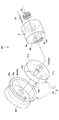
- FIG. 2 is an exploded perspective view of the rotary valve RV
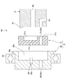
- FIG. 3 is a sectional view of the rotary valve RV in an exploded state
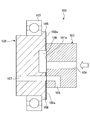
- FIG. 4 is a sectional view of the assembled rotary valve RV.
- the rotary valve RV is disposed between the intake port 1a and the discharge port 1b of the compressor 1 and the upper chamber 13 in the refrigerant gas flow path.
- the rotary valve RV has a function of switching the flow path of the refrigerant gas.
- the rotary valve RV has a first mode for guiding the refrigerant gas discharged from the discharge port 1b of the gas compressor 1 into the upper chamber 13, and the refrigerant gas in the upper chamber 13 of the gas compressor 1. Switching processing to the second mode leading to the intake port 1a is performed.
- the rotary valve RV has a valve body 8 and a valve plate 9.
- the valve plate 9 includes a valve plate body 30 and a valve sliding member 31 (this will be described in detail later).
- the valve plate 9 is rotatably supported in the housing 23 by a rotary bearing 16.
- the eccentric pin 14a of the crank 14 that drives the scotch yoke 22 revolves around the rotation axis, the valve plate 9 rotates.
- the valve body 8 is pressed against the valve plate 9 by a coil spring 20 and is fixed so as not to rotate by a pin 19.
- the coil spring 20 is provided with pressing means for pressing the valve body 8 so that the valve body 8 does not move away from the valve plate 9 when the pressure on the exhaust side becomes larger than the pressure on the supply side. It is.
- the force that presses the valve body 8 against the valve plate 9 during operation is generated by the pressure difference between the supply side pressure and the exhaust side pressure of the refrigerant gas acting on the valve body 8.
- the valve body 8 has a cylindrical shape.
- a flat sliding surface 8 a is formed on the surface of the valve body 8 facing the valve plate 9, and the sliding surface 8 a is in surface contact with the sliding surface 31 a of the valve sliding member 31 constituting the valve plate 9. To do.
- the first gas flow path 8b (first main body side flow path) is formed through the valve main body 8 along the central axis of the valve main body 8. One end of the first gas channel 8b is open to the sliding surface 8a. The other end of the first gas flow path 8b is connected to the discharge port 1b of the gas compressor 1 shown in FIG.
- a groove 8 c is formed on the sliding surface 8 a of the valve body 8 along an arc centered on the central axis of the valve body 8.
- the valve main body 8 is formed with a second gas flow path 8d (second main body side flow path) having an inverted L shape in a side view.
- One end of the second gas flow path 8 d opens at the bottom surface of the groove 8 c, and the other end opens at the outer peripheral surface of the valve body 8.
- An end portion of the first gas flow path 8b opened in the outer peripheral surface of the valve body 8 communicates with the upper chamber 13 via a gas flow path 21 formed in the housing 23 shown in FIG.
- the groove 31d extending in the radial direction from the center is formed on the sliding surface 31a of the valve plate 9 (valve sliding member 31).
- the valve plate 9 rotates and the outer peripheral end of the groove 31a partially overlaps the groove 8c, the first gas flow path 8b and the second gas flow path 8d communicate with each other via the groove 31a. .
- the plate-side gas flow path 9b (configured by the gas flow paths 30b and 31b) extends through the valve plate 9 (the valve plate body 30 and the valve sliding member 31) in a direction parallel to the rotation axis. ing. One end of the plate-side gas flow path 9b is open to the sliding surface 31a. The end of the plate-side gas flow path 9b is opened at a position corresponding to the groove 8c formed in the sliding surface 8a in the sliding surface 31a.
- the second gas passage 8d and the plate side gas passage 9b is in a state of communication.
- the other end of the plate-side gas flow path 9b communicates with the intake port 1a of the gas compressor 1 through the cavity in the housing 23 shown in FIG.
- the refrigerant gas sent from the compressor 1 is sent into the upper chamber 13 via the rotary valve RV.
- the second gas flow path 8d and the plate-side gas flow path 9b communicate with each other, the refrigerant gas in the upper chamber 13 is recovered by the gas compressor 1. Therefore, when the valve plate 9 is rotated, the introduction (supply) of the refrigerant gas into the upper chamber 13 and the recovery (exhaust) of the refrigerant gas from the upper chamber 13 are repeated.
- valve body 8 and the valve plate 9 will be described in more detail.
- the valve body 8 serving as the stator (fixed side) is formed of a metal such as hardened steel. Even if the valve body 8 is formed of such a metal, which is a magnetic material, the valve body 8 does not rotate. Therefore, even if the cryogenic refrigerator and the rotary valve RV are applied to MRI or the like, The magnetic field is not disturbed due to the cryogenic refrigerator and the rotary valve RV.
- the material of the valve body 8 is not limited to a magnetic material, and a nonmagnetic material such as an alumite-treated aluminum surface can also be used.
- valve plate 9 is composed of a valve plate body 30 and a valve sliding member 31.
- the valve plate body 30 is made of stainless steel, which is a nonmagnetic metal material.
- the valve plate body 30 is rotatably supported by the housing 23 by the rotary bearing 16. Therefore, a flange 30e that engages with the rotary bearing 16 is formed on the front side of the valve plate main body 30 (the side facing the valve main body 8).
- a storage chamber 30 a for storing the valve sliding member 31 is formed on the surface of the valve plate body 30 facing the valve body 8.
- the storage chamber 30a has a recessed shape, and a detent pin 30c (corresponding to a rotation restricting member described in claims) is formed on the bottom surface.
- the detent pin 30 c is engaged with a detent recess 30 f formed in the valve plate body 30 and a detent recess 31 c formed in the valve slide member 31, so that the valve slide member 31 with respect to the valve plate body 30 is engaged. Regulate the rotation of However, the non-rotating pin 30c does not completely fix the valve sliding member 31 to the valve plate main body 30, but only functions to restrict rotation. Therefore, the valve sliding member 31 is configured to be attachable / detachable to / from the valve plate body 30 (attachable / detachable in the rotation axis direction).
- valve plate body 30 is formed with a gas flow path 30b that constitutes a part of the plate-side gas flow path 9b.
- the gas flow path 30 b is formed through the bottom plate portion of the storage chamber 30 a of the valve plate body 30. Therefore, one end of the gas flow path 30b opens to the bottom surface of the storage chamber 30a, and the other end communicates with the intake port 1a of the gas compressor 1 through the cavity in the housing 23 as described above.
- the valve sliding member 31 is made of resin and has a disk shape.
- the resin used for the valve sliding member 31 is made of, for example, tetrafluoroethylene (for example, BEAREE FL3000 manufactured by NTN).
- the valve sliding member 31 has the groove 31 d formed on a sliding surface 31 a that is in close contact with the valve body 8.
- the valve sliding member 31 is formed with a gas passage 31b that constitutes the plate-side gas passage 9b.
- the gas flow path 31b communicates with the gas flow path 30b formed in the valve plate main body 30 when the valve sliding member 31 is mounted in the storage chamber 30a of the valve plate main body 30 so that the plate side gas flow path 9b is Form.
- valve plate main body 30 when the valve plate main body 30 is rotated by the driving means in a state where the valve sliding member 31 is mounted, the valve sliding member mounted in a state in which the rotation is restricted to the valve plate main body 30 by the detent pin 30c. 31 also starts to rotate.
- the valve plate 9 the valve plate body 30, the valve sliding member 31
- the first gas flow path 8b and the second gas flow path 8d are grooved 31d as described above. Is switched between the state in which the second gas passage 8d is connected to the valve plate 9 and the state in which the second gas flow path 8d is connected to the valve plate 9.
- the valve plate body 30 is made of a nonmagnetic metal material such as stainless steel, and the valve sliding member 31 is also made of a nonmagnetic resin. For this reason, even if the cryogenic refrigerator and the rotary valve RV according to the present embodiment are used in an environment that does not like the fluctuation of the magnetic field, the magnetic field is disturbed by the rotation of the valve plate body 30 and the valve sliding member 31. There is nothing.
- the sliding surface 31 a of the valve plate 9 is formed on the resin valve sliding member 31. Therefore, the alumite treatment that is necessary for the conventional valve plate 102 made of aluminum can be eliminated, and the cost of the valve plate 9 can be reduced.
- the sliding surface 101a and the sliding surface 102a are both consumable parts in the prior art, and therefore the valve body 101 and the valve plate 102 are both replaced (See FIG. 5).
- the valve plate main body 30 there is no consumable part in the valve plate main body 30 and the valve sliding member 31 is detachable from the valve plate main body 30. It is only necessary to replace the 8-valve sliding member 31.
- the valve plate main body 30 is expensive with respect to the valve sliding member 31 because it is necessary to provide the storage chamber 30a, the gas flow path 30b, the rotation stopper pin 30c and the like in stainless steel. Therefore, at the time of maintenance, it is only necessary to replace the valve sliding member 31 and the valve body 8, which are inexpensive, with respect to the valve plate body 30. Therefore, it is possible to reduce the cost of replacement parts at the time of maintenance.
Landscapes
- Engineering & Computer Science (AREA)
- General Engineering & Computer Science (AREA)
- Mechanical Engineering (AREA)
- Physics & Mathematics (AREA)
- Thermal Sciences (AREA)
- Multiple-Way Valves (AREA)
- Sliding Valves (AREA)
Abstract
Description
本体側流路が形成されたバルブ本体と、プレート側流路が形成されたバルブプレートとを有しており、前記バルブ本体の本体側摺動面を前記バルブプレートのプレート側摺動面に密着させると共に、前記バルブプレートを回転させることにより、前記本体側流路と前記プレート側流路の接続状態を切換えるロータリバルブであって、
前記バルブプレートを、前記プレート側摺動面を有する樹脂製のバルブ摺動体と、該バルブ摺動体を収納する収納室が形成された非磁性材よりなるバルブプレート本体とを有する構成としたことを特徴とするものである。
吸気口から吸入された冷媒ガスを圧縮して排出口に排出するする圧縮機と、
前記冷媒ガスが供給されるシリンダと、
該シリンダ内で往復移動して前記シリンダ内で圧縮された前記冷媒ガスを膨張させるディスプレーサと、
前記ディスプレーサを前記シリンダ内で往復移動させる駆動装置と、
上記のロータリバルブとを有しており、
前記バルブ本体の前記本体側流路を、前記排出口に接続される第1の本体側流路と、前記シリンダに接続される第2の本体側流路とにより構成し、
前記ロータリバルブの前記バルブプレートに形成されたプレート側流路を前記吸気口に接続するよう構成し、
前記バルブプレートが回転することにより、前記第2の本体側流路が前記第1の本体側流路又は前記プレート側流路に選択的に接続するよう構成したことを特徴とするものである。
2 コールドヘッド
3A 第1段目ディスプレーサ
3B 第2段目ディスプレーサ
4A,4B 蓄冷材
6,7 冷却ステージ
8 バルブ本体
8a 摺動面
8b 第1のガス流路
8c 溝8c 名詞
8d 第2のガス流路
9 バルブプレート
9b プレート側ガス流路
10 シリンダ部
10A 第1段目シリンダ
10B 第2段目シリンダ
11 第1段目膨張室
12 第2段目膨張室
13 上部室
14 クランク
15 モータ
16 回転軸受
22 スコッチヨーク
30 バルブプレート本体
30a 収納室
30b ガス流路
30c 回り止めピン
31 バルブ摺動部材
31a 摺動面
31b ガス流路
31c 回り止め凹部
31d 溝31
Claims (5)
- 本体側流路が形成されたバルブ本体と、プレート側流路が形成されたバルブプレートとを有しており、前記バルブ本体の本体側摺動面を前記バルブプレートのプレート側摺動面に密着させると共に、前記バルブプレートを回転させることにより、前記本体側流路と前記プレート側流路の接続状態を切換えるロータリバルブであって、
前記バルブプレートを、前記プレート側摺動面を有する樹脂製のバルブ摺動体と、該バルブ摺動体を収納する収納室が形成された非磁性材よりなるバルブプレート本体とを有する構成としたことを特徴とするロータリバルブ。 - 前記バルブプレートは、前記バルブ摺動体の前記バルブプレート本体に対する回転を規制する回転規制部材を有することを特徴とする請求項1記載のロータリバルブ。
- 前記バルブ摺動体は、前記バルブプレート本体に対して着脱可能な構成であることを特徴とする請求項1記載のロータリバルブ。
- 前記バルブ本体は、磁性材料により形成されてなることを特徴とする請求項1記載のロータリバルブ。
- 吸気口から吸入された冷媒ガスを圧縮して排出口に排出するする圧縮機と、
前記冷媒ガスが供給されるシリンダと、
該シリンダ内で往復移動して前記シリンダ内で圧縮された前記冷媒ガスを膨張させるディスプレーサと、
前記ディスプレーサを前記シリンダ内で往復移動させる駆動装置と、
請求項1記載のロータリバルブとを有しており、
前記バルブ本体の前記本体側流路を、前記排出口に接続される第1の本体側流路と、前記シリンダに接続される第2の本体側流路とにより構成し、
前記ロータリバルブの前記バルブプレートに形成されたプレート側流路を前記吸気口に接続するよう構成し、
前記バルブプレートが回転することにより、前記第2の本体側流路が前記第1の本体側流路又は前記プレート側流路に選択的に接続するよう構成したことを特徴とするロータリバルブを用いた極低温冷凍機。
Priority Applications (4)
| Application Number | Priority Date | Filing Date | Title |
|---|---|---|---|
| KR1020127030266A KR101498348B1 (ko) | 2010-04-19 | 2011-04-12 | 로터리밸브 및 이를 사용한 극저온냉동기 |
| CN201180019700.XA CN102844634B (zh) | 2010-04-19 | 2011-04-12 | 回转阀及使用该回转阀的超低温制冷机 |
| JP2012511618A JP5710602B2 (ja) | 2010-04-19 | 2011-04-12 | ロータリバルブ及びこれを用いた極低温冷凍機 |
| US13/649,300 US20130025297A1 (en) | 2010-04-19 | 2012-10-11 | Rotary valve and cryogenic refrigerator using same |
Applications Claiming Priority (2)
| Application Number | Priority Date | Filing Date | Title |
|---|---|---|---|
| JP2010-095921 | 2010-04-19 | ||
| JP2010095921 | 2010-04-19 |
Related Child Applications (1)
| Application Number | Title | Priority Date | Filing Date |
|---|---|---|---|
| US13/649,300 Continuation US20130025297A1 (en) | 2010-04-19 | 2012-10-11 | Rotary valve and cryogenic refrigerator using same |
Publications (1)
| Publication Number | Publication Date |
|---|---|
| WO2011132563A1 true WO2011132563A1 (ja) | 2011-10-27 |
Family
ID=44834089
Family Applications (1)
| Application Number | Title | Priority Date | Filing Date |
|---|---|---|---|
| PCT/JP2011/059053 Ceased WO2011132563A1 (ja) | 2010-04-19 | 2011-04-12 | ロータリバルブ及びこれを用いた極低温冷凍機 |
Country Status (5)
| Country | Link |
|---|---|
| US (1) | US20130025297A1 (ja) |
| JP (1) | JP5710602B2 (ja) |
| KR (1) | KR101498348B1 (ja) |
| CN (1) | CN102844634B (ja) |
| WO (1) | WO2011132563A1 (ja) |
Cited By (9)
| Publication number | Priority date | Publication date | Assignee | Title |
|---|---|---|---|---|
| JP2013104563A (ja) * | 2011-11-14 | 2013-05-30 | Idex Health & Science Llc | ポリマインサートデバイスを伴う回転せん断バルブアセンブリ |
| JP2013142479A (ja) * | 2012-01-06 | 2013-07-22 | Sumitomo Heavy Ind Ltd | 極低温冷凍機、ディスプレーサ |
| WO2013126113A1 (en) * | 2012-02-23 | 2013-08-29 | Cameron International Corporation | Rotating compressor valve |
| US20140338367A1 (en) * | 2013-05-16 | 2014-11-20 | Sumitomo Heavy Industries, Ltd. | Cryogenic refrigerator |
| JP2017523397A (ja) * | 2014-06-02 | 2017-08-17 | ネクストテック エルエルシー | サンプリング装置のためのフロータイマー |
| JP2017166746A (ja) * | 2016-03-16 | 2017-09-21 | 住友重機械工業株式会社 | 極低温冷凍機およびロータリバルブ機構 |
| WO2018168304A1 (ja) * | 2017-03-13 | 2018-09-20 | 住友重機械工業株式会社 | 極低温冷凍機及び極低温冷凍機用のロータリーバルブユニット |
| US10551093B2 (en) | 2016-03-16 | 2020-02-04 | Sumitomo Heavy Industries, Ltd. | Cryocooler and rotary valve mechanism |
| JP2020073841A (ja) * | 2019-11-11 | 2020-05-14 | 住友重機械工業株式会社 | Gm冷凍機 |
Families Citing this family (15)
| Publication number | Priority date | Publication date | Assignee | Title |
|---|---|---|---|---|
| JP6017327B2 (ja) * | 2013-01-21 | 2016-10-26 | 住友重機械工業株式会社 | 極低温冷凍機 |
| CN106660651B (zh) | 2014-05-06 | 2019-06-21 | 吉玛股份公司 | 旋转分配器 |
| KR101667933B1 (ko) | 2014-07-18 | 2016-10-21 | 한국과학기술연구원 | 선형 제어가 가능한 튜브체를 구비하는 튜브 연속체 로봇 |
| KR101700885B1 (ko) | 2015-06-23 | 2017-02-01 | 한국과학기술연구원 | 복수의 튜브 연속체를 사용한 수술용 로봇 시스템 |
| CN105065717B (zh) * | 2015-07-22 | 2017-07-07 | 珠海格力电器股份有限公司 | 一种换向阀及空调机组 |
| JP2017120162A (ja) * | 2015-12-28 | 2017-07-06 | 住友重機械工業株式会社 | 極低温冷凍機およびロータリバルブ機構 |
| JP6636356B2 (ja) * | 2016-02-18 | 2020-01-29 | 住友重機械工業株式会社 | 極低温冷凍機 |
| JP6563441B2 (ja) * | 2017-06-26 | 2019-08-21 | 株式会社不二工機 | パイロット式電磁弁 |
| CN108507215B (zh) * | 2018-04-19 | 2019-11-19 | 中船重工鹏力(南京)超低温技术有限公司 | 一种配气机构及采用该配气机构的低温制冷机 |
| CN108518504B (zh) | 2018-04-19 | 2019-11-15 | 中船重工鹏力(南京)超低温技术有限公司 | 自减压配气机构及采用该自减压配气机构的低温制冷机 |
| CN108825841B (zh) * | 2018-07-02 | 2019-08-30 | 广东省新材料研究所 | 一种g-m型低温制冷机旋转阀体及其制备方法 |
| JP7164340B2 (ja) | 2018-07-11 | 2022-11-01 | 住友重機械工業株式会社 | 極低温冷凍機および極低温冷凍機の流路切替機構 |
| CN111853285B (zh) * | 2020-08-10 | 2025-03-25 | 中船鹏力(南京)超低温技术有限公司 | 一种具有预紧力的旋转阀及采用该旋转阀的低温制冷机 |
| CN111854210B (zh) * | 2020-08-10 | 2024-09-10 | 中船鹏力(南京)超低温技术有限公司 | 一种具有防旋转机构的低温制冷机 |
| CN112413176B (zh) * | 2020-11-09 | 2023-10-10 | 深圳供电局有限公司 | 一种旋转阀机构以及低温制冷机 |
Citations (4)
| Publication number | Priority date | Publication date | Assignee | Title |
|---|---|---|---|---|
| JPS58166172A (ja) * | 1982-03-26 | 1983-10-01 | Osaka Oxgen Ind Ltd | ロ−タリ−バルブ |
| JP2001280728A (ja) * | 2000-03-30 | 2001-10-10 | Sumitomo Heavy Ind Ltd | 冷凍機、直動機構、ロータリバルブ |
| JP2001349630A (ja) * | 2000-06-06 | 2001-12-21 | Sumitomo Heavy Ind Ltd | ロータリバルブ及びそれを用いた冷凍機 |
| JP2007205581A (ja) * | 2006-01-30 | 2007-08-16 | Sumitomo Heavy Ind Ltd | 蓄冷器式冷凍機 |
Family Cites Families (17)
| Publication number | Priority date | Publication date | Assignee | Title |
|---|---|---|---|---|
| US902264A (en) * | 1907-04-20 | 1908-10-27 | Arthur Eddy J | Fluid-controlling means. |
| US1292829A (en) * | 1917-06-14 | 1919-01-28 | George H Lutz | Valve mechanism. |
| US3620029A (en) * | 1969-10-20 | 1971-11-16 | Air Prod & Chem | Refrigeration method and apparatus |
| US3625015A (en) * | 1970-04-02 | 1971-12-07 | Cryogenic Technology Inc | Rotary-valved cryogenic apparatus |
| US3742979A (en) * | 1972-03-02 | 1973-07-03 | G Woodling | Rotary valve device having a plurality of controlled working passages |
| JPS58199172A (ja) * | 1982-05-14 | 1983-11-19 | Nec Corp | 放電記録ヘツドの製造方法 |
| JPS60138369A (ja) * | 1983-12-26 | 1985-07-23 | セイコー精機株式会社 | ガス冷凍機 |
| US4520630A (en) * | 1984-03-06 | 1985-06-04 | Cvi Incorporated | Cryogenic refrigerator and heat source |
| JPH0395324U (ja) * | 1990-01-18 | 1991-09-27 | ||
| WO1993010407A1 (fr) * | 1991-11-18 | 1993-05-27 | Sumitomo Heavy Industries, Ltd. | Appareil refrigerant cryogenique |
| JP3207903B2 (ja) * | 1992-01-16 | 2001-09-10 | 株式会社フジユニバンス | 油圧式動力伝達継手 |
| JP3224600B2 (ja) * | 1992-07-24 | 2001-10-29 | 株式会社フジユニバンス | 油圧式動力伝達継手 |
| JPH10132404A (ja) * | 1996-10-24 | 1998-05-22 | Suzuki Shiyoukan:Kk | パルス管冷凍機 |
| US6920845B2 (en) * | 2003-08-14 | 2005-07-26 | Visteon Global Technologies, Inc. | Engine cooling disc valve |
| WO2005088210A1 (en) * | 2004-03-08 | 2005-09-22 | Sumitomo Heavy Industries, Ltd. | Wearless valve for cryorefrigerator |
| JP5025643B2 (ja) * | 2005-06-10 | 2012-09-12 | 住友重機械工業株式会社 | パルスチューブ冷凍機用マルチプルロータリバルブ |
| US8016264B2 (en) * | 2006-05-02 | 2011-09-13 | Teijin Pharma Limited | Rotary-valve and adsorption separation system |
-
2011
- 2011-04-12 JP JP2012511618A patent/JP5710602B2/ja active Active
- 2011-04-12 WO PCT/JP2011/059053 patent/WO2011132563A1/ja not_active Ceased
- 2011-04-12 KR KR1020127030266A patent/KR101498348B1/ko active Active
- 2011-04-12 CN CN201180019700.XA patent/CN102844634B/zh active Active
-
2012
- 2012-10-11 US US13/649,300 patent/US20130025297A1/en not_active Abandoned
Patent Citations (4)
| Publication number | Priority date | Publication date | Assignee | Title |
|---|---|---|---|---|
| JPS58166172A (ja) * | 1982-03-26 | 1983-10-01 | Osaka Oxgen Ind Ltd | ロ−タリ−バルブ |
| JP2001280728A (ja) * | 2000-03-30 | 2001-10-10 | Sumitomo Heavy Ind Ltd | 冷凍機、直動機構、ロータリバルブ |
| JP2001349630A (ja) * | 2000-06-06 | 2001-12-21 | Sumitomo Heavy Ind Ltd | ロータリバルブ及びそれを用いた冷凍機 |
| JP2007205581A (ja) * | 2006-01-30 | 2007-08-16 | Sumitomo Heavy Ind Ltd | 蓄冷器式冷凍機 |
Cited By (14)
| Publication number | Priority date | Publication date | Assignee | Title |
|---|---|---|---|---|
| JP2013104563A (ja) * | 2011-11-14 | 2013-05-30 | Idex Health & Science Llc | ポリマインサートデバイスを伴う回転せん断バルブアセンブリ |
| JP2013142479A (ja) * | 2012-01-06 | 2013-07-22 | Sumitomo Heavy Ind Ltd | 極低温冷凍機、ディスプレーサ |
| US8974201B2 (en) | 2012-02-23 | 2015-03-10 | Ge Oil & Gas Compression Systems, Llc | Rotating compressor valve |
| WO2013126113A1 (en) * | 2012-02-23 | 2013-08-29 | Cameron International Corporation | Rotating compressor valve |
| US9657970B2 (en) | 2013-05-16 | 2017-05-23 | Sumitomo Heavy Industries, Ltd. | Cryogenic refrigerator |
| JP2014224656A (ja) * | 2013-05-16 | 2014-12-04 | 住友重機械工業株式会社 | 極低温冷凍機 |
| US20140338367A1 (en) * | 2013-05-16 | 2014-11-20 | Sumitomo Heavy Industries, Ltd. | Cryogenic refrigerator |
| JP2017523397A (ja) * | 2014-06-02 | 2017-08-17 | ネクストテック エルエルシー | サンプリング装置のためのフロータイマー |
| JP2017166746A (ja) * | 2016-03-16 | 2017-09-21 | 住友重機械工業株式会社 | 極低温冷凍機およびロータリバルブ機構 |
| US10551093B2 (en) | 2016-03-16 | 2020-02-04 | Sumitomo Heavy Industries, Ltd. | Cryocooler and rotary valve mechanism |
| WO2018168304A1 (ja) * | 2017-03-13 | 2018-09-20 | 住友重機械工業株式会社 | 極低温冷凍機及び極低温冷凍機用のロータリーバルブユニット |
| JP2018151129A (ja) * | 2017-03-13 | 2018-09-27 | 住友重機械工業株式会社 | 極低温冷凍機及び極低温冷凍機用のロータリーバルブユニット |
| US11221079B2 (en) | 2017-03-13 | 2022-01-11 | Sumitomo Heavy Industries, Ltd. | Cryocooler and rotary valve unit for cryocooler |
| JP2020073841A (ja) * | 2019-11-11 | 2020-05-14 | 住友重機械工業株式会社 | Gm冷凍機 |
Also Published As
| Publication number | Publication date |
|---|---|
| CN102844634B (zh) | 2015-08-26 |
| KR101498348B1 (ko) | 2015-03-03 |
| KR20130018303A (ko) | 2013-02-20 |
| JPWO2011132563A1 (ja) | 2013-07-18 |
| CN102844634A (zh) | 2012-12-26 |
| JP5710602B2 (ja) | 2015-04-30 |
| US20130025297A1 (en) | 2013-01-31 |
Similar Documents
| Publication | Publication Date | Title |
|---|---|---|
| JP5710602B2 (ja) | ロータリバルブ及びこれを用いた極低温冷凍機 | |
| JP5996483B2 (ja) | 極低温冷凍機 | |
| TWI473956B (zh) | Cooler type freezer | |
| CN102844633B (zh) | 超低温制冷机 | |
| US11221079B2 (en) | Cryocooler and rotary valve unit for cryocooler | |
| JP4197341B2 (ja) | 蓄冷器式冷凍機 | |
| JP6214498B2 (ja) | 極低温冷凍機 | |
| TWI460386B (zh) | Very low temperature freezer | |
| JP2010271029A (ja) | 蓄冷式冷凍機、蓄冷式冷凍機用ロータリバルブの製造方法、および蓄冷式冷凍機の製造方法 | |
| US11971108B2 (en) | Rotary valve of cryocooler and cryocooler | |
| JP2014224656A (ja) | 極低温冷凍機 | |
| JP5877543B2 (ja) | ディスプレーサ及びその製造方法及び蓄冷器式冷凍機 | |
| JP6305287B2 (ja) | 極低温冷凍機 | |
| JP2017215095A (ja) | 極低温冷凍機 | |
| JP6771293B2 (ja) | Gm冷凍機 | |
| JP2001349630A (ja) | ロータリバルブ及びそれを用いた冷凍機 | |
| JP6773872B2 (ja) | Gm冷凍機 | |
| CN115077115B (zh) | 超低温制冷机 | |
| TW202323742A (zh) | 極低溫冷凍機之分解方法 | |
| JP2007205582A (ja) | 蓄冷器式冷凍機 | |
| JP2003262417A (ja) | 冷凍機の高低圧ガス切換弁 |
Legal Events
| Date | Code | Title | Description |
|---|---|---|---|
| WWE | Wipo information: entry into national phase |
Ref document number: 201180019700.X Country of ref document: CN |
|
| 121 | Ep: the epo has been informed by wipo that ep was designated in this application |
Ref document number: 11771898 Country of ref document: EP Kind code of ref document: A1 |
|
| WWE | Wipo information: entry into national phase |
Ref document number: 2012511618 Country of ref document: JP |
|
| NENP | Non-entry into the national phase |
Ref country code: DE |
|
| ENP | Entry into the national phase |
Ref document number: 20127030266 Country of ref document: KR Kind code of ref document: A |
|
| 122 | Ep: pct application non-entry in european phase |
Ref document number: 11771898 Country of ref document: EP Kind code of ref document: A1 |