WO2011132474A1 - 車両用ドアロック装置 - Google Patents
車両用ドアロック装置 Download PDFInfo
- Publication number
- WO2011132474A1 WO2011132474A1 PCT/JP2011/055632 JP2011055632W WO2011132474A1 WO 2011132474 A1 WO2011132474 A1 WO 2011132474A1 JP 2011055632 W JP2011055632 W JP 2011055632W WO 2011132474 A1 WO2011132474 A1 WO 2011132474A1
- Authority
- WO
- WIPO (PCT)
- Prior art keywords
- housing
- vehicle door
- door lock
- lock device
- communication path
- Prior art date
Links
Images


Classifications
-
- E—FIXED CONSTRUCTIONS
- E05—LOCKS; KEYS; WINDOW OR DOOR FITTINGS; SAFES
- E05B—LOCKS; ACCESSORIES THEREFOR; HANDCUFFS
- E05B85/00—Details of vehicle locks not provided for in groups E05B77/00 - E05B83/00
- E05B85/02—Lock casings
-
- E—FIXED CONSTRUCTIONS
- E05—LOCKS; KEYS; WINDOW OR DOOR FITTINGS; SAFES
- E05B—LOCKS; ACCESSORIES THEREFOR; HANDCUFFS
- E05B77/00—Vehicle locks characterised by special functions or purposes
- E05B77/34—Protection against weather or dirt, e.g. against water ingress
-
- E—FIXED CONSTRUCTIONS
- E05—LOCKS; KEYS; WINDOW OR DOOR FITTINGS; SAFES
- E05B—LOCKS; ACCESSORIES THEREFOR; HANDCUFFS
- E05B81/00—Power-actuated vehicle locks
- E05B81/02—Power-actuated vehicle locks characterised by the type of actuators used
- E05B81/04—Electrical
- E05B81/06—Electrical using rotary motors
-
- E—FIXED CONSTRUCTIONS
- E05—LOCKS; KEYS; WINDOW OR DOOR FITTINGS; SAFES
- E05B—LOCKS; ACCESSORIES THEREFOR; HANDCUFFS
- E05B81/00—Power-actuated vehicle locks
- E05B81/12—Power-actuated vehicle locks characterised by the function or purpose of the powered actuators
- E05B81/16—Power-actuated vehicle locks characterised by the function or purpose of the powered actuators operating on locking elements for locking or unlocking action
-
- Y—GENERAL TAGGING OF NEW TECHNOLOGICAL DEVELOPMENTS; GENERAL TAGGING OF CROSS-SECTIONAL TECHNOLOGIES SPANNING OVER SEVERAL SECTIONS OF THE IPC; TECHNICAL SUBJECTS COVERED BY FORMER USPC CROSS-REFERENCE ART COLLECTIONS [XRACs] AND DIGESTS
- Y10—TECHNICAL SUBJECTS COVERED BY FORMER USPC
- Y10T—TECHNICAL SUBJECTS COVERED BY FORMER US CLASSIFICATION
- Y10T292/00—Closure fasteners
- Y10T292/48—Seals
Definitions
- the present invention relates to a vehicle door lock device.
- a vehicle door can be held in a closed state with respect to a body, and a latch mechanism that is assembled to the door together with a housing; and a housing that is assembled to the housing and provided on the door
- a lever mechanism that is driven by the operation of the door handle, and an lever that is interposed in the housing between the latch mechanism and the lever mechanism, and that enables transmission of an operating force from the lever mechanism to the latch mechanism.
- a link mechanism that can be switched to a locked state or a locked state that disables transmission of the operating force, and an electric actuator (electrical component) that is assembled in the housing and switches the link mechanism to the unlocked state or the locked state.
- the housing is provided with a waterproof measure for the electric actuator (electrical component) described above.
- the above-mentioned waterproof measures described in Patent Document 1 provide a waterproof cover above the housing and prevent water from entering the housing space of the housing in which the electric actuator (electrical component) is housed.
- a water passage hole is provided in the upper part of the housing.
- the present invention has been made to solve the above-described problems, and is capable of holding a vehicle door closed with respect to a body, and is adapted to be assembled to the door together with a housing; A lever mechanism that is assembled to the housing and adapted to be driven by operation of a door handle provided on the door; and the lever mechanism is interposed between the latch mechanism and the lever mechanism in the housing.
- a link mechanism that can be switched to an unlocked state that enables operation force transmission from the mechanism to the latch mechanism or a locked state that disables the operation force transmission, and is assembled in the housing, and the link mechanism is
- the housing includes an electric actuator that switches to the unlocked state or the locked state, and the housing is joined to each other.
- a housing including a main body and a housing cover, the joint surfaces of which are arranged so as to extend in the vertical direction, and a housing for housing the link mechanism and the electric actuator at a joint portion between the housing main body and the housing cover
- a seal portion is formed so as to surround an upper portion of the inner space.
- the seal portion includes a communication passage formed at the joint portion and having at least one end opened, and the inside of the communication passage and the outside of the housing.
- An inner weld portion and an outer weld portion that are continuously formed along the communication path are provided.
- the communication path is constituted by a communication groove formed in one of the housing body and the housing cover, and an end wall formed in the other of the housing body and the housing cover and closing the communication groove.
- the inner welded portion and the outer welded portion may be formed by laser welding.
- the housing body is formed of a laser light non-transparent resin material
- the housing cover is formed of a laser beam.
- the inner welded portion and the outer welded portion can be laser welded by being irradiated with laser light from the housing cover side.
- the communication path may be open at one end and closed at the other end, and the inner welded portion and the outer welded portion may be connected at the closed end. Further, both ends of the communication path may be opened downward.
- the communication path is formed by the inner welded portion and the outer welded portion except for both ends. It is sealed. For this reason, by sealing pressurized gas (for example, compressed air) in the communication path and inspecting the gas pressure, the sealing performance (air tightness / liquid tightness) at the sealing portion described above can be easily achieved. It is possible to determine.
- pressurized gas for example, compressed air
- the communication path is formed by a communication groove formed in one of the housing main body and the housing cover, and an end wall formed in the other of the housing main body and the housing cover and closing the communication groove.
- the communication path can be formed simply and inexpensively.
- the inner welded portion and the outer welded portion are formed by laser welding, it is possible to suppress the influence on the components in the housing as compared with the case where the inner welded portion and the outer welded portion are formed by vibration welding. is there.
- the communication path is open at one end and closed at the other end, and when the inner welded portion and the outer welded portion are connected at the closed end,
- a connecting device capable of enclosing a pressurized gas (for example, compressed air) in the communication path to the opening end and inspecting the gas pressure, the sealing performance at the above-described sealing portion ( It is possible to easily determine whether the airtightness and liquid tightness are good or bad.
- both ends of the communication passage are open downward, even if water may enter the housing through the outer welded portion, Water is captured in the communication passage and is prevented from entering the upper portion of the space in the housing. Further, the water trapped in the communication path does not drop from the end of the communication path downward and enter the upper part of the space in the housing. Therefore, it is possible to accurately prevent water from above from entering the upper portion of the space in the housing.
- FIG. 1 is a side view of an embodiment of a vehicle door lock device according to the present invention as seen from the inside of a vehicle.
- FIG. 2 is a view in which an operation cable and a housing cover are removed from the vehicle door lock device shown in FIG.
- FIG. 3 is a cross-sectional view taken along line AA in FIG. 4 is a cross-sectional view taken along line BB in FIG.
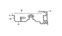
- FIG. 5 is an enlarged view of the seal portion of FIG.
- FIGS. 1 to 5 show a vehicle door lock device 100 according to the present invention.
- This vehicle door lock device 100 is mounted on a door 201 provided on the front right side of the vehicle.
- a lever mechanism 20, a link mechanism 30, and an electric actuator 40 which are assembled to the housing 50.
- the latch mechanism 10 is for holding a vehicle door 201 in a closed state (a state in which the door 201 is closed) with respect to a body (a vehicle body not shown), and is a striker fixed to the body. (Not shown) is provided with a latch 11 that can be engaged and disengaged.
- the latch mechanism 10 is assembled to the door 201 in a state assembled to the housing 50.
- the lever mechanism 20 includes an inside open lever 21 that is driven by an inside door handle (not shown) provided inside the door 201 and an outside door handle (not shown) provided outside the door 201.
- the outside open lever 22 is provided to be driven along with this.
- the inside open lever 21 is assembled to the housing 50, and is linked to the inside door handle via the operation cable 61 (which can also be implemented by an operation force transmission member such as a link) shown in FIG. It is driven by operating the handle.
- the outside open lever 22 is assembled to the housing 50, and is linked to the outside door handle via an operating force transmission member (not shown) such as a link, and is driven by the operation of the inside door handle.
- the link mechanism 30 is interposed between the latch mechanism 10 and the lever mechanism 20 in the housing 50, and is in an unlocked state in which the operation force transmission from the lever mechanism 20 to the latch mechanism 10 is effective or the operation force transmission.
- An open link 31 that can be switched to an invalid lock state is provided.
- the open link 31 is interposed between the inside open lever 21 and the outside open lever 22 provided in the lever mechanism 20 and a lift lever (not shown) provided in the latch mechanism 10, and is used for door opening operation of each door handle.
- the door open direction operation of each open lever 21 and 22 can be switched to an unlock position (operation force transmission is enabled) and a lock position that is not transmitted to the lift lever (operation force transmission is disabled) can be switched. It is.
- the electric actuator 40 is assembled in the housing 50, and the link mechanism 30 can be switched to an unlocked state or a locked state.
- the electric actuator 40 includes an electric motor 41, a worm 42, and a worm wheel 43, and an active lever 44 driven by them.
- the active lever 44 is connected to a lock knob (not shown) provided on the vehicle inner side of the door 201 via the operation cable 62 shown in FIG. 1, and the lock lever (not shown) can be manually operated. It is configured to be drivable.
- the active lever 44 is also connected to a key cylinder (not shown) provided outside the door 201, and can be driven by manually operating the key cylinder (not shown).
- the housing 50 includes a housing body 51 and a housing cover 52 joined to each other, and these joining surfaces are arranged so as to extend in the vertical direction.
- a seal portion S is formed at a joint portion between the housing body 51 and the housing cover 52 so as to surround an upper portion of the housing inner space R that houses the link mechanism 30 and the electric actuator 40.
- the seal portion S is provided with a communication path P (see a broken line in FIG. 1) formed at the joint portion and having one end Pa opened and the other end Pb closed. Further, as shown exaggeratedly in FIG. 5, an inner welded portion Wi and an outer welded portion Wo are continuously formed along the communicating passage P on the inner side and the outer side of the communicating passage P. .
- the communication path P is constituted by a communication groove 51a having a rectangular cross section formed in the housing body 51 and an end wall 52a formed in the housing cover 52 and closing the communication groove 51a.
- the communication path (P) can also be constituted by a communication groove formed in the housing cover (52) and an end wall formed in the housing body (51) to close the communication groove.
- the inner welded portion Wi and the outer welded portion Wo are formed by laser welding. Further, the inner welded portion Wi and the outer welded portion Wo are connected at the closed end Pb of the communication passage P, and the periphery of the communication passage P is hermetically and liquid-tightly sealed except for the opening end Pa of the communication passage P. is doing. Further, in this embodiment, the housing body 51 is formed of a laser light non-transmissive resin material, and the housing cover 52 is formed of a laser light transparent resin material, which is necessary for desired laser welding from the housing cover 52 side. A laser beam having a light density is irradiated.
- the seal portion S formed at the joint between the housing body 51 and the housing cover 52 is configured as described above. Water from above that drops and adheres to the upper portion of the housing 50 is prevented from entering the inner space R housing the link mechanism 30 and the electric actuator 40 by the seal portion S described above. For this reason, in this embodiment, it is possible to protect the link mechanism 30 and the electric actuator 40 from water with a simple and inexpensive configuration without using a waterproof cover.
- the inner welded portion Wi and the outer welded portion Wo are continuously formed along the communication path P in the seal portion S described above, and are connected at the closed end Pb of the communication path P. Therefore, the communication path P is hermetically and liquid-tightly sealed by the inner welded portion Wi and the outer welded portion Wo except for the opening end Pa. For this reason, a connecting tool (not shown) capable of enclosing a pressurized gas (for example, compressed air) in the communication path P and inspecting the gas pressure is connected to the opening end of the communication path P.
- a pressurized gas for example, compressed air
- the communication path P is constituted by the communication groove 51a formed in the housing body 51 and the end wall 52a formed in the housing cover 52 and closing the communication groove 51a.
- it can be formed at low cost.
- the inner welded portion Wi and the outer welded portion Wo are formed by laser welding, it is possible to suppress the influence on the components in the housing 50 as compared with the case where the inner welded portion Wi and the outer welded portion Wo are formed by vibration welding. .
- the communication path P has one end Pa opened and the other end Pb closed. However, both ends of the communication path (P) may be opened downward. It is. In this case, even if water may intrude into the housing (50) through the outer welded portion (Wo), the water is captured by the communication path (P) and the housing inner space (R) ) Is prevented from entering the upper part. Further, the water trapped in the communication path (P) does not drop downward from the end of the communication path (P) and enter the upper portion of the housing inner space (R). Therefore, it is possible to accurately prevent water from above from entering the upper portion of the housing inner space (R).
Landscapes
- Lock And Its Accessories (AREA)
Abstract
Description
ところで、上記した特許文献1に記載されている車両用ドアロック装置では、防水用のカバーを必要とするため、部品点数が増加する。また、ハウジングの上部に設けた通水孔は、所期の機能を発揮して所期の防水効果は期待できるものの、ハウジングの上部に落下して付着した水の全ては通水孔に流入する保証がなくて、電動アクチュエータ(電装部品)が収容されているハウジングの収容空間に水が浸入するおそれがある。
本発明は、上記した課題を解決すべくなされたものであり、車両のドアをボデーに対して閉じた状態で保持可能であり、ハウジングとともに前記ドアに組付けられるよう適合されるラッチ機構と、前記ハウジングに組付けられて前記ドアに設けたドアハンドルの操作により駆動されるよう適合されるレバー機構と、前記ハウジング内にて前記ラッチ機構と前記レバー機構間に介装されていて、前記レバー機構から前記ラッチ機構への操作力伝達を有効とするアンロック状態または前記操作力伝達を無効とするロック状態に切り替え可能なリンク機構と、前記ハウジング内に組付けられていて、前記リンク機構を前記アンロック状態または前記ロック状態に切り替える電動アクチュエータを備え、前記ハウジングは、互いに接合されたハウジング本体とハウジングカバーを備えていて、これらの接合面が上下方向に沿って延びるように配置され、前記ハウジング本体と前記ハウジングカバーとの接合部には、前記リンク機構と前記電動アクチュエータを収容するハウジング内空間の上方部分を包囲するようにシール部が形成され、このシール部には、前記接合部に形成されて少なくとも一端が開口する連通路と、この連通路のハウジング内側とハウジング外側にて前記連通路に沿って連続的に形成された内側溶着部および外側溶着部とが設けられている。
本発明による車両用ドアロック装置においては、ハウジング本体とハウジングカバーとの接合部に形成されているシール部が、上記したように構成されているため、ハウジングの上部に落下して付着した上方からの水は、上記したシール部によって、リンク機構と電動アクチュエータを収容するハウジング内空間への浸入を阻止される。このため、本発明では、防水用のカバーを用いることなく、シンプルかつ安価な構成で、リンク機構と電動アクチュエータを水から保護することが可能である。
Claims (6)
- 車両のドアをボデーに対して閉じた状態で保持可能であり、ハウジングとともに前記ドアに組付けられるよう適合されるラッチ機構と、
前記ハウジングに組付けられて前記ドアに設けたドアハンドルの操作により駆動されるよう適合されるレバー機構と、
前記ハウジング内にて前記ラッチ機構と前記レバー機構間に介装されていて、前記レバー機構から前記ラッチ機構への操作力伝達を有効とするアンロック状態または前記操作力伝達を無効とするロック状態に切り替え可能なリンク機構と、
前記ハウジング内に組付けられていて、前記リンク機構を前記アンロック状態または前記ロック状態に切り替える電動アクチュエータを備え、
前記ハウジングは、互いに接合されたハウジング本体とハウジングカバーを備えていて、これらの接合面が上下方向に沿って延びるように配置され、
前記ハウジング本体と前記ハウジングカバーとの接合部には、前記リンク機構と前記電動アクチュエータを収容するハウジング内空間の上方部分を包囲するようにシール部が形成され、
このシール部には、前記接合部に形成されて少なくとも一端が開口する連通路と、この連通路のハウジング内側とハウジング外側にて前記連通路に沿って連続的に形成された内側溶着部および外側溶着部とが設けられている車両用ドアロック装置。 - 請求項1に記載の車両用ドアロック装置において、
前記連通路は、前記ハウジング本体および前記ハウジングカバーの一方に形成した連通溝と、前記ハウジング本体および前記ハウジングカバーの他方に形成されて前記連通溝を塞ぐ端壁によって構成されている車両用ドアロック装置。 - 請求項1または2に記載の車両用ドアロック装置において、
前記内側溶着部と前記外側溶着部は、レーザー溶着によって形成されている車両用ドアロック装置。 - 請求項3に記載の車両用ドアロック装置において、
前記ハウジング本体は、レーザー光非透過性樹脂材料で形成され、
前記ハウジングカバーは、レーザー光透過性樹脂材料で形成され、
前記ハウジングカバー側からレーザー光を照射することにより、前記内側溶着部と前記外側溶着部はレーザー溶着される車両用ドアロック装置。 - 請求項1~4の何れか一項に記載の車両用ドアロック装置において、
前記連通路は一端が開口し他端が閉塞していて、閉塞端では前記内側溶着部と前記外側溶着部が接続されている車両用ドアロック装置。 - 請求項1~4の何れか一項に記載の車両用ドアロック装置において、
前記連通路は両端が下方に向けて開口している車両用ドアロック装置。
Priority Applications (4)
| Application Number | Priority Date | Filing Date | Title |
|---|---|---|---|
| EP20110771814 EP2562336B1 (en) | 2010-04-22 | 2011-03-10 | Vehicle door lock device |
| US13/637,183 US20130015673A1 (en) | 2010-04-22 | 2011-03-10 | Vehicle door lock device |
| BR112012026905A BR112012026905A2 (pt) | 2010-04-22 | 2011-03-10 | dispositivo de travamento de porta de veículo |
| CN2011800159807A CN102822434A (zh) | 2010-04-22 | 2011-03-10 | 车辆用门锁装置 |
Applications Claiming Priority (2)
| Application Number | Priority Date | Filing Date | Title |
|---|---|---|---|
| JP2010098734A JP5365574B2 (ja) | 2010-04-22 | 2010-04-22 | 車両用ドアロック装置 |
| JP2010-098734 | 2010-04-22 |
Publications (1)
| Publication Number | Publication Date |
|---|---|
| WO2011132474A1 true WO2011132474A1 (ja) | 2011-10-27 |
Family
ID=44834013
Family Applications (1)
| Application Number | Title | Priority Date | Filing Date |
|---|---|---|---|
| PCT/JP2011/055632 WO2011132474A1 (ja) | 2010-04-22 | 2011-03-10 | 車両用ドアロック装置 |
Country Status (6)
| Country | Link |
|---|---|
| US (1) | US20130015673A1 (ja) |
| EP (1) | EP2562336B1 (ja) |
| JP (1) | JP5365574B2 (ja) |
| CN (1) | CN102822434A (ja) |
| BR (1) | BR112012026905A2 (ja) |
| WO (1) | WO2011132474A1 (ja) |
Cited By (1)
| Publication number | Priority date | Publication date | Assignee | Title |
|---|---|---|---|---|
| WO2013065593A1 (ja) * | 2011-11-01 | 2013-05-10 | アイシン精機株式会社 | ドアロック装置 |
Families Citing this family (17)
| Publication number | Priority date | Publication date | Assignee | Title |
|---|---|---|---|---|
| JP6067979B2 (ja) * | 2012-03-14 | 2017-01-25 | アイシン機工株式会社 | 壁体固着部構造及び車両部品の製造方法 |
| DE112014004455T5 (de) * | 2013-09-25 | 2016-06-23 | Magna Closures S.P.A. | Elektrisches Fahrzeugschloss |
| CN204571599U (zh) * | 2014-02-14 | 2015-08-19 | 因特瓦产品有限责任公司 | 具有一体的附接结构的锁闩壳体 |
| JP6454908B2 (ja) * | 2014-07-18 | 2019-01-23 | 三井金属アクト株式会社 | 車両用ドアラッチ装置 |
| JP6515303B2 (ja) * | 2015-07-07 | 2019-05-22 | 三井金属アクト株式会社 | 車両用ドアロック装置 |
| JP6572486B2 (ja) * | 2016-02-26 | 2019-09-11 | 三井金属アクト株式会社 | ドアロック装置およびその製造方法 |
| DE102016206400A1 (de) * | 2016-04-15 | 2017-10-19 | Bühler Motor GmbH | Stellantrieb und Verfahren zur Herstellung eines Stellantriebs |
| JP6652709B2 (ja) * | 2016-07-15 | 2020-02-26 | 株式会社アンセイ | 車両用ドアロック装置 |
| CN107620529B (zh) * | 2016-07-15 | 2020-12-15 | 株式会社安成 | 车辆用门锁装置 |
| JP6627671B2 (ja) * | 2016-07-15 | 2020-01-08 | 株式会社アンセイ | 車両用ドアロック装置 |
| JP6627672B2 (ja) | 2016-07-20 | 2020-01-08 | 株式会社アンセイ | 車両用ドアロック装置 |
| JP6627729B2 (ja) | 2016-11-25 | 2020-01-08 | 株式会社アンセイ | 車両用ドアロック装置 |
| JP6762242B2 (ja) * | 2017-01-30 | 2020-09-30 | ジーコム コーポレイションGecom Corporation | 車両用ドアラッチ装置 |
| JP6772215B2 (ja) * | 2018-05-28 | 2020-10-21 | 三井金属アクト株式会社 | ドアロック装置対 |
| JP6627920B2 (ja) | 2018-06-26 | 2020-01-08 | 株式会社アンセイ | 車両用ドアロック装置 |
| WO2021019856A1 (ja) * | 2019-07-31 | 2021-02-04 | 三井金属アクト株式会社 | ドアラッチ装置 |
| DE102020132170A1 (de) | 2020-12-03 | 2022-06-09 | Brose Schließsysteme GmbH & Co. Kommanditgesellschaft | Funktionseinheit für das Betätigen eines Kraftfahrzeugschlosses |
Citations (2)
| Publication number | Priority date | Publication date | Assignee | Title |
|---|---|---|---|---|
| JP2006233506A (ja) | 2005-02-23 | 2006-09-07 | Aisin Seiki Co Ltd | ドアロック装置 |
| JP2008063913A (ja) * | 2006-09-11 | 2008-03-21 | Mitsui Mining & Smelting Co Ltd | アクチュエータユニット |
Family Cites Families (6)
| Publication number | Priority date | Publication date | Assignee | Title |
|---|---|---|---|---|
| JP3079611B2 (ja) * | 1991-03-29 | 2000-08-21 | アイシン精機株式会社 | リツドロツク装置 |
| FR2783551B1 (fr) * | 1998-09-21 | 2000-11-17 | Valeo Securite Habitacle | Serrure electrique perfectionnee pour portiere de vehicule automobile |
| JP2004251106A (ja) * | 2003-01-30 | 2004-09-09 | Aisin Seiki Co Ltd | ドアロック装置 |
| US20100072761A1 (en) * | 2008-02-04 | 2010-03-25 | Kris Tomaszewski | Global Side Door Latch |
| JP4542166B2 (ja) * | 2008-03-26 | 2010-09-08 | 三井金属鉱業株式会社 | ドアロック装置 |
| DE202008004332U1 (de) * | 2008-03-29 | 2009-08-06 | Kiekert Ag | Kraftfahrzeug-Türschloss |
-
2010
- 2010-04-22 JP JP2010098734A patent/JP5365574B2/ja not_active Expired - Fee Related
-
2011
- 2011-03-10 US US13/637,183 patent/US20130015673A1/en not_active Abandoned
- 2011-03-10 CN CN2011800159807A patent/CN102822434A/zh active Pending
- 2011-03-10 BR BR112012026905A patent/BR112012026905A2/pt not_active Application Discontinuation
- 2011-03-10 EP EP20110771814 patent/EP2562336B1/en not_active Not-in-force
- 2011-03-10 WO PCT/JP2011/055632 patent/WO2011132474A1/ja active Application Filing
Patent Citations (2)
| Publication number | Priority date | Publication date | Assignee | Title |
|---|---|---|---|---|
| JP2006233506A (ja) | 2005-02-23 | 2006-09-07 | Aisin Seiki Co Ltd | ドアロック装置 |
| JP2008063913A (ja) * | 2006-09-11 | 2008-03-21 | Mitsui Mining & Smelting Co Ltd | アクチュエータユニット |
Non-Patent Citations (1)
| Title |
|---|
| See also references of EP2562336A4 |
Cited By (2)
| Publication number | Priority date | Publication date | Assignee | Title |
|---|---|---|---|---|
| WO2013065593A1 (ja) * | 2011-11-01 | 2013-05-10 | アイシン精機株式会社 | ドアロック装置 |
| JP2013096144A (ja) * | 2011-11-01 | 2013-05-20 | Aisin Kiko Co Ltd | ドアロック装置 |
Also Published As
| Publication number | Publication date |
|---|---|
| BR112012026905A2 (pt) | 2016-07-12 |
| CN102822434A (zh) | 2012-12-12 |
| JP2011226194A (ja) | 2011-11-10 |
| EP2562336A4 (en) | 2013-07-03 |
| EP2562336A1 (en) | 2013-02-27 |
| US20130015673A1 (en) | 2013-01-17 |
| EP2562336B1 (en) | 2014-04-23 |
| JP5365574B2 (ja) | 2013-12-11 |
Similar Documents
| Publication | Publication Date | Title |
|---|---|---|
| WO2011132474A1 (ja) | 車両用ドアロック装置 | |
| JP2011226194A5 (ja) | ||
| ES2726656T3 (es) | Equipo de control de válvula y válvula de proceso | |
| WO2014045731A1 (ja) | 車両用ドアロック装置 | |
| US20130023141A1 (en) | Charging coupling and charging coupling arrangement for a motor vehicle, and motor vehicle | |
| KR20150063923A (ko) | 리드장치 | |
| CN1375032A (zh) | 特别用于机动车的锁系统 | |
| CN105658889A (zh) | 电车辆闩锁 | |
| JP2017166286A (ja) | 車両用ドアラッチ装置 | |
| ES2280833T3 (es) | Puerta de avion con un mecanismo de apertura y un dispositivo para advertir de una diferencia de presion al abrir la puerta de avion solicitada por la presion. | |
| US20150233151A1 (en) | Motor vehicle door lock | |
| CN102199962A (zh) | 门锁装置 | |
| US7758098B2 (en) | Device for making accessible and closing an opening in a vehicle body | |
| WO2015015291A1 (en) | Motor vehicle door lock | |
| KR100889852B1 (ko) | 공기조화용 댐퍼장치 | |
| CN117677752A (zh) | 机动车锁、特别是机动车门锁 | |
| JP2008545966A (ja) | 相互密封連結チャンバをそれぞれ有する二つの設備機器を切り離すシステム | |
| US20160348407A1 (en) | Housing for a latch with water drain opening and method of draining water from a latch | |
| CA2489465A1 (en) | A lock for a door of a motor vehicle | |
| JP2018040195A (ja) | 車両用ドアラッチ装置 | |
| KR200446927Y1 (ko) | 방독면의 마이크단자용 밀폐커버 | |
| JP2000027514A (ja) | 車両ドアラッチユニット | |
| KR100614588B1 (ko) | 맨홀 뚜껑의 결속장치 | |
| WO2010136825A1 (en) | Detachable and replaceable ion source for a mass spectrometer | |
| JP2009215874A (ja) | 自動車用ドアラッチ装置 |
Legal Events
| Date | Code | Title | Description |
|---|---|---|---|
| WWE | Wipo information: entry into national phase |
Ref document number: 201180015980.7 Country of ref document: CN |
|
| 121 | Ep: the epo has been informed by wipo that ep was designated in this application |
Ref document number: 11771814 Country of ref document: EP Kind code of ref document: A1 |
|
| WWE | Wipo information: entry into national phase |
Ref document number: 13637183 Country of ref document: US |
|
| WWE | Wipo information: entry into national phase |
Ref document number: 2011771814 Country of ref document: EP |
|
| WWE | Wipo information: entry into national phase |
Ref document number: 8942/CHENP/2012 Country of ref document: IN |
|
| NENP | Non-entry into the national phase |
Ref country code: DE |
|
| WWE | Wipo information: entry into national phase |
Ref document number: 1201005532 Country of ref document: TH |
|
| REG | Reference to national code |
Ref country code: BR Ref legal event code: B01A Ref document number: 112012026905 Country of ref document: BR |
|
| ENP | Entry into the national phase |
Ref document number: 112012026905 Country of ref document: BR Kind code of ref document: A2 Effective date: 20121019 |