WO2011129423A1 - Rotor phase/velocity estimation device for alternating-current motor - Google Patents
Rotor phase/velocity estimation device for alternating-current motor Download PDFInfo
- Publication number
- WO2011129423A1 WO2011129423A1 PCT/JP2011/059337 JP2011059337W WO2011129423A1 WO 2011129423 A1 WO2011129423 A1 WO 2011129423A1 JP 2011059337 W JP2011059337 W JP 2011059337W WO 2011129423 A1 WO2011129423 A1 WO 2011129423A1
- Authority
- WO
- WIPO (PCT)
- Prior art keywords
- frequency
- phase
- rotor
- current
- axis
- Prior art date
Links
Images


Classifications
-
- H—ELECTRICITY
- H02—GENERATION; CONVERSION OR DISTRIBUTION OF ELECTRIC POWER
- H02P—CONTROL OR REGULATION OF ELECTRIC MOTORS, ELECTRIC GENERATORS OR DYNAMO-ELECTRIC CONVERTERS; CONTROLLING TRANSFORMERS, REACTORS OR CHOKE COILS
- H02P21/00—Arrangements or methods for the control of electric machines by vector control, e.g. by control of field orientation
- H02P21/14—Estimation or adaptation of machine parameters, e.g. flux, current or voltage
- H02P21/18—Estimation of position or speed
-
- H—ELECTRICITY
- H02—GENERATION; CONVERSION OR DISTRIBUTION OF ELECTRIC POWER
- H02P—CONTROL OR REGULATION OF ELECTRIC MOTORS, ELECTRIC GENERATORS OR DYNAMO-ELECTRIC CONVERTERS; CONTROLLING TRANSFORMERS, REACTORS OR CHOKE COILS
- H02P21/00—Arrangements or methods for the control of electric machines by vector control, e.g. by control of field orientation
- H02P21/24—Vector control not involving the use of rotor position or rotor speed sensors
- H02P21/26—Rotor flux based control
-
- H—ELECTRICITY
- H02—GENERATION; CONVERSION OR DISTRIBUTION OF ELECTRIC POWER
- H02P—CONTROL OR REGULATION OF ELECTRIC MOTORS, ELECTRIC GENERATORS OR DYNAMO-ELECTRIC CONVERTERS; CONTROLLING TRANSFORMERS, REACTORS OR CHOKE COILS
- H02P2203/00—Indexing scheme relating to controlling arrangements characterised by the means for detecting the position of the rotor
- H02P2203/11—Determination or estimation of the rotor position or other motor parameters based on the analysis of high frequency signals
Definitions
- the present invention relates to an AC motor in which the rotor exhibits salient pole characteristics with respect to a high-frequency current having a frequency higher than the drive frequency (for example, a permanent magnet synchronous motor having a permanent magnet in the rotor, a wound synchronous motor, a synchronous reluctance motor, a rotor
- a permanent magnet synchronous motor having a permanent magnet in the rotor
- a wound synchronous motor for example, a wound synchronous motor, a synchronous reluctance motor, a rotor
- the rotor phase (synonymous with position) and speed used in the drive control system for a hybrid field type synchronous motor, induction motor, etc. having permanent magnets and field windings in the same position are utilized using a position speed sensor.
- the present invention relates to a rotor phase speed estimation apparatus for estimation without performing sensor, that is, sensorless.
- High performance control of AC motors can be achieved by the so-called vector control method.
- the vector control method requires information on the rotor phase or speed, which is a differential value thereof, and a position speed sensor such as an encoder has been conventionally used.
- a position speed sensor such as an encoder has been conventionally used.
- the use of this type of position / velocity sensor is not preferable in terms of reliability, axial volume, sensor cable routing, cost, etc., and so-called sensorless vector control method that does not require a position / velocity sensor.
- the rotor phase to be estimated may be determined at an arbitrary position of the rotor. However, when the rotor exhibits salient pole characteristics, either the negative salient pole phase or the positive salient pole phase of the rotor is used as the rotor phase. Generally, it is selected. As is well known to those skilled in the art, there is only an electrical phase difference of ⁇ ⁇ / 2 (rad) between the negative salient pole phase and the positive salient pole phase. The other phases are naturally found. Considering the above, hereinafter, the negative salient pole phase of the rotor will be referred to as the rotor phase unless otherwise specified.
- the high-frequency voltage application method in a broad sense includes a narrow-sense high-frequency voltage application method that determines the method of generating the high-frequency voltage to be applied, and a phase estimation that determines the generation of the rotor phase estimate by processing the high-frequency current that is the response of the applied high-frequency voltage. Composed as a combination with law.
- an alternating high-frequency voltage having zero DC component and a constant high frequency is often used.
- a typical signal shape of the alternating high-frequency voltage a sine shape and a rectangular shape are known.
- Narrowly defined high-frequency voltage application methods that apply sinusoidal high-frequency voltage include generalized elliptical high-frequency voltage application method, constant circular high-frequency voltage application method (constant amplitude true-circular high-frequency voltage application method), linear high-frequency voltage application method Etc. are known.
- a sine-shaped high-frequency voltage with a high frequency ⁇ h is converted into a ⁇ quasi-synchronous coordinate system with a coordinate speed ⁇ ⁇ (which is orthogonal to the ⁇ axis that aims at synchronization with a constant phase difference represented by a zero phase difference in the rotor phase).
- a sinusoidal high-frequency voltage by the generalized elliptical high-frequency voltage application method is expressed by the following equation (in this specification, signals related to the high-frequency voltage and the high-frequency current): Etc., this is clearly indicated by adding a h to the signal etc.).
- the sinusoidal high-frequency voltage by the constant true high-frequency voltage application method is expressed by the following equation.
- the sinusoidal high-frequency voltage obtained by the linear high-frequency voltage application method is expressed by the following equation.
- the signal of each high-frequency voltage vector element is a sine shape expressed as a cosine function or a trigonometric function of a sine function. I am doing.
- the variable of the trigonometric function at this time is ⁇ h t which is a time integral value of the high frequency ⁇ h .
- the sinusoidal high-frequency voltage is not limited to the formulas (1) to (3), but can be variously considered including a combination of the formulas (1) to (3).
- the following high-frequency voltage can be obtained by a combination of Equation (2) and Equation (3).
- the rectangular high-frequency voltage can be expressed by using the sign function sgn (•) as follows, referring to the expression method of the sine-shaped high-frequency voltage. Also in the rectangular high-frequency voltage of Expression (6), the DC component does not exist and is zero as in the case of the sinusoidal high-frequency voltage.
- the high frequency voltage command value is superimposed and added to the driving voltage command value to synthesize the stator voltage command value, and the combined stator voltage command value is input to the power converter (inverter). do it.
- a high frequency voltage can be applied to the electric motor.
- the narrowly defined high-frequency voltage application method dealt with by the present invention is to apply a high-frequency voltage as expressed by equations (1) to (6).
- These high-frequency voltages have the characteristic that “the fundamental wave component draws an elliptical locus on the ⁇ quasi-synchronous coordinate system”.
- An ellipse generally has a different ratio between its short axis and long axis.
- the perfect circular locus is treated as an elliptical locus having a minor axis ratio of 1.
- the linear trajectory is treated as an elliptical trajectory having a minor axis ratio of zero.
- a high frequency current is generated as a response.
- the high-frequency current is affected by the salient pole characteristics, and as a result, the high-frequency current has salient pole phase information, that is, rotor phase information.
- the desired rotor phase information can be extracted through the processing of the high-frequency current that contains the rotor phase information.
- the stator current detected from the stator terminal of the AC motor includes a driving current having a driving frequency and a high frequency current having a high frequency.
- a filtering process which is a typical dynamic process, is generally used for separating and extracting a high-frequency current from a stator current (see Patent Documents 1 to 5 and Non-Patent Document 1 described later). reference).
- Non-Patent Document 1 As described in detail in Non-Patent Document 1, conventionally, the design of a band-pass filter for high-frequency current separation and extraction has been made on a trial and error basis, and much effort is required for this appropriate design (Non-Patent Document 1). 1). In addition, every time the high frequency of the applied high-frequency voltage is changed, it is necessary to redesign the band-pass filter that requires trial and error (see Non-Patent Document 1).
- the extracted high-frequency current causes phase advance due to the unavoidable nature of the high-pass filter, which makes it difficult to correctly estimate the phase.
- various components beyond the frequency of the high-frequency current are also taken in at the same time, which makes it difficult to estimate accurately.
- Patent Documents 3 to 5 “Apply rectangular high frequency alternating voltage consisting of two pulse voltages having the same amplitude and pulse width and different polarities in a plurality of vector directions”. Some of them require complicated high-frequency voltage applying means.
- the present invention has been made under the above background, and the objects thereof are as follows.
- High stability in principle which does not require dynamic processing for separating and extracting high-frequency current from stator current, or does not require any narrow-band filter that accurately extracts only high-frequency components.
- a phase velocity estimation apparatus that has a phase delay and no lead.
- a phase velocity estimation device that is capable of generating a correlation signal that can have a wide positive correlation region and that is unlikely to cause estimation instability due to sudden disturbance.
- An easy-to-implement phase velocity estimation device that can use simple high-frequency voltage application means is provided.
- the invention of claim 1 is a function of applying a stator voltage and detecting a stator current for an AC motor in which the rotor exhibits salient pole characteristics for a high-frequency current having a frequency higher than the drive frequency.
- Correlation signal generating means for generating a correlation signal having a correlation with the rotor phase evaluated on the coordinate system, and using the correlation signal, the phase of the ⁇ quasi-synchronous coordinate system and the estimated value of the rotor phase or the rotor Rotor phase generation means for generating at least one of the estimated values of the rotor speed basically having a calculus relationship with the phase is provided.
- the invention of claim 2 is used in a drive control device having a function of applying a stator voltage and detecting a stator current for an AC motor in which a rotor exhibits salient pole characteristics with respect to a high-frequency current having a frequency higher than the drive frequency.
- Rotator phase speed estimation device which is a ⁇ quasi-synchronization consisting of a ⁇ axis that aims to synchronize with a phase of a rotating rotor with a constant phase difference represented by a zero phase difference, and a ⁇ axis orthogonal thereto
- a high-frequency voltage applying means configured to superimpose a high-frequency voltage having a direct current component of zero and a high frequency ⁇ h as a fundamental frequency on the driving voltage on the coordinate system, and applying the stator current to the AC motor;
- the high frequency ⁇ h is obtained as the fundamental frequency for any one of the ⁇ -axis element and the ⁇ -axis element corresponding to the high-frequency current obtained by processing the stator current or the stator current obtained from the drive control device.
- a high-frequency current fundamental wave component amplitude extracting means for extracting the first order Fourier coefficient equivalent value, and a correlation signal having a correlation with the rotor phase obtained by evaluating the extracted Fourier coefficient equivalent value on the ⁇ quasi-synchronous coordinate system Using the Fourier coefficient equivalent value itself or a multiple of this value, the phase of the ⁇ quasi-synchronous coordinate system and the estimated value of the rotor phase or the rotor speed basically in a calculus relationship with the rotor phase
- Rotor phase generation means for generating at least one estimated value of the estimated value is provided.
- a third aspect of the present invention is the rotor phase speed estimation device according to the first or second aspect, wherein the high-frequency voltage in the high-frequency voltage applying means is a triangle with a time integral value of the high frequency ⁇ h as a variable.
- a sinusoidal voltage expressed by a function is used.
- FIG. 1 shows a dq synchronous coordinate system in which the d-axis (main axis) is completely synchronized with the rotor phase without a phase difference, an ⁇ fixed coordinate system in which the ⁇ -axis (main axis) phase is the same as the u-phase winding phase of the stator, and rotation.
- a ⁇ quasi-synchronous coordinate system having a ⁇ axis (principal axis) aimed at synchronization with a constant phase difference represented by a zero phase difference to the child phase is drawn.
- the instantaneous speed of the rotor in the ⁇ quasi-synchronous coordinate system is expressed by ⁇ .
- the rotor is assumed to have a phase ⁇ ⁇ instantaneously with respect to the ⁇ axis.
- the rotation from the main axis ( ⁇ axis) to the sub axis ( ⁇ axis) is the positive direction.
- the ⁇ quasi-synchronous coordinate system aims to synchronize with the rotor phase with a zero phase difference without losing generality. In other words, it is aimed to converge on the dq synchronous coordinate system.
- the electric motor rotates in the positive direction including zero speed.
- the fundamental frequency ⁇ h of the high-frequency voltage superimposed on the driving voltage for rotor phase estimation is positive. This premise is for the purpose of simplifying the explanation, so that the generality of the explanation and the essence of the principle of the present invention are not lost.
- the above assumptions are naturally applied to the high-frequency voltages shown in equations (1) to (6).
- the high-frequency voltage having a sine shape can be expressed using any trigonometric function of cosine function (cos function) or sine function (sin function).
- cos function cos function
- sine function sin function
- the simplicity of the description is ensured.
- the ⁇ -axis element (first element) of the applied voltage is expressed by a cosine function like the high-frequency voltages shown in Expressions (1) to (5).
- the phase of another signal is expressed based on the ⁇ -axis element (first element) of the applied voltage.
- the Fourier series includes a complex Fourier series and a triangular Fourier series, but the essence is the same. In the description of the effect of the present invention, a triangular Fourier series is used for simplicity.
- T 1 in the equations (7b) and (7c) that determine the determination of the triangular Fourier coefficients a n and b n is an arbitrary time in the time domain in which the periodic signal is defined.
- Equation (1) When the generalized elliptical high-frequency voltage of Equation (1) is applied to an AC motor whose rotor exhibits salient pole characteristics with respect to the high-frequency current, the next high-frequency current flows as a response to the applied high-frequency voltage.
- L d and L q are d-axis and q-axis inductances for a high-frequency current
- L i and L m are in-phase and mirror-phase inductances having the following relationship with the d-axis and q-axis inductances.
- Equation (2) When the constant true circular high-frequency voltage of Equation (2) is applied to an AC motor whose rotor exhibits salient pole characteristics with respect to the high-frequency current, the following high-frequency current flows as this response.
- the high frequency current as a response can be generally expressed as follows.
- the symbols ⁇ and ⁇ in the above formula mean the ⁇ -axis element and ⁇ -axis element of the high-frequency current as a 2 ⁇ 1 vector on the ⁇ quasi-synchronous coordinate system.
- I i in the equation (12) is an amplitude component caused by a high frequency voltage, a frequency, a stator inductance, and the like.
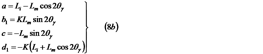
- a, b i , c, d i are amplitude components including the rotor phase.
- stator current i 1 corresponding to this is described as follows from the equation (12).
- the stator current i 1 is expressed as a vector sum of the driving current i 1f and the high-frequency current i 1h . Note that the symbol f indicates a drive signal.
- the rotor phase information is included in the amplitudes a, b i , c, d i of the high frequency components. These amplitudes can be extracted as follows using the Fourier coefficient determination method given in Equation (7b) and Equation (7c).
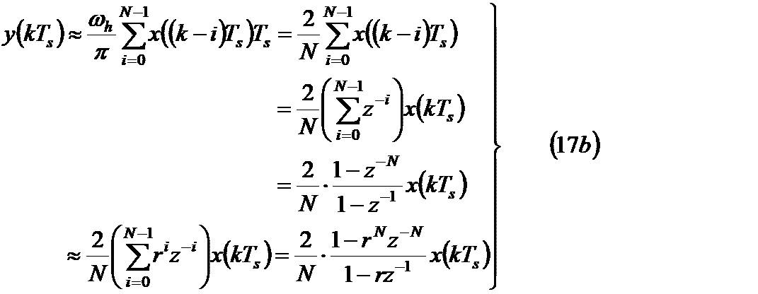
- the definite integral of equation (14) is approximated in discrete time.
- Sampling period T s for discrete-time reduction is referred to as being in the relationship of the period T h and the next as integer N of the formula (22).
- the definite integral of the following equation (17a) is discretely approximated for each sampling period as shown in equation (17b).
- t kT s
- z ⁇ 1 is a delay operator as explicitly shown in the equation (17c).
- r is a maximum value less than 1 that can be handled by the microcomputer.
- the high-frequency current fundamental wave component amplitude extracting means in the first aspect of the invention obtains the stator current from the drive control device and processes the stator current or the stator current, and the ⁇ -axis element of the high-frequency current equivalent value obtained by processing the stator current and ⁇ Both the axial elements are subjected to processing equivalent to Fourier series expansion with the high frequency ⁇ h as the fundamental frequency to extract the value corresponding to the first order Fourier coefficient. More specifically, a Fourier coefficient process of Expression (14) is applied to the stator current of Expression (13), and this first-order Fourier coefficient equivalent value is obtained. To extract. The Fourier coefficient processing of equation (14) is actually performed by discrete time approximation as in equation (17), which is one of the equivalent processes.
- the integral coefficient ⁇ h / ⁇ in the equations (14) and (17a) for determining the value corresponding to the first order Fourier coefficient, and the approximate integral coefficient 2 in the equation (17b). / N can be removed or changed.
- the present invention uses the term “first-order Fourier coefficient equivalent value” instead of the first-order Fourier coefficient itself.
- the definite integration process of equation (14) can be approximately performed by a low-pass filter process.
- the following approximation is established between the definite integration process of Expression (17a) and the process by the low-pass filter F (s).
- the expression “processing equivalent to Fourier series expansion” is used in consideration of the approximation processing such as Expression (18).
- the Fourier coefficient equivalent value is obtained by performing processing equivalent to Fourier series expansion on the stator current itself. That is, it is not always necessary to extract the high-frequency current in advance. Even when a high frequency current is extracted using a DC cut filter, it is possible to use a DC cut filter having a sufficiently wide band without impairing the stability of the estimation system. That is, a rough process for extracting a high-frequency current is sufficient.
- the high-frequency voltage applying means for applying such a high-frequency voltage for generating a high-frequency current is a high-frequency voltage having a DC component of zero and a high frequency ⁇ h as a fundamental frequency, as specified in the invention of claim 1. What is necessary is just to superimpose on the drive voltage and to apply to this AC motor.
- the non-sinusoidal high-frequency voltage for example, the one represented by Equation (6) can be considered.
- the correlation signal having a correlation with the rotor phase evaluated on the ⁇ quasi-synchronous coordinate system using the Fourier coefficient equivalent value extracted from the ⁇ -axis and ⁇ -axis elements by the correlation signal generating means Is generated.
- This correlation signal is substantially the same as the rotor phase ⁇ ⁇ . That is, this correlation signal has the maximum positive correlation region ⁇ ⁇ / 2 (rad) in any high frequency voltage application method. Furthermore, it is characterized by insensitivity to the amplitude and frequency of the applied high-frequency voltage and insensitivity to motor parameters. The calculation load is also relatively small. On the other hand, it cannot be used for a high-frequency voltage application method in which the amplitudes of the positive-phase component and the negative-phase component of the high-frequency current are substantially the same.
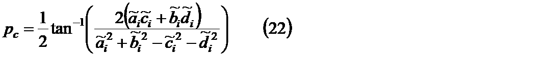
- the method of generating the correlation signal p c with an emphasis on versatility positive correlation region there are at least following.
- the correlation signal of Equation (22) is also the long axis phase ⁇ ⁇ e of the elliptical locus of the high-frequency current (see FIG. 2), and has a strong positive correlation with the rotor phase. It has versatility that it can be applied to all high frequency voltage application methods.
- this correlation signal has a feature that the calculation load is slightly increased as compared with the equations (19) to (21).
- the method of generating the correlation signal p c where a positive correlation region emphasizing calculation load there are at least following.
- the correlation signal of Expression (23) has a positive correlation region equivalent to that of Expression (22), but the calculation load is reduced compared to Expression (22).
- this is comparable for the computational load.
- equation (23) is excellent, but as for the positive correlation region, equations (19) and (20) are excellent.
- FIG. 3B shows the correlation characteristics between the rotor phase and this correlation signal.
- This correlation signal has a significant decrease in the positive correlation area as a price for versatility and simplification.
- an electric motor of 0.1 only a positive correlation region of about 0.8 (rad) is obtained.
- the positive correlation signal generation method exemplified in the equations (19) to (24) is a high-frequency component amplitude (first-order Fourier coefficient).
- the relative ratio is used. Therefore, when these positive correlation signal generation methods are used, the integral coefficient ⁇ h / ⁇ in the expressions (14) and (17a) for determining the first-order Fourier coefficient equivalent value, and the approximate integral coefficient in the expression (17b) It is possible to remove or change 2 / N.
- the rotor phase generation means uses the correlation signal and the phase of the ⁇ quasi-synchronous coordinate system and the estimated value of the rotor phase or the rotor speed basically in a calculus relationship with the rotor phase. And at least one of the estimated values.
- the rotor phase generation means may be simply configured based on the generalized integral PLL method.
- the generalized integral PLL method (see Non-Patent Document 2 etc.) is given by the following equation.
- phase controller can obtain sufficient performance with the following primary controller (PI controller).
- PI controller primary controller
- ⁇ in equation (25b) is the velocity of the ⁇ quasi-synchronous coordinate system
- equation (25c) Is a phase evaluated from the ⁇ axis of the ⁇ quasi-synchronous coordinate system.
- the invention of claim 1 can provide the effect that the following characteristics can be given to the phase velocity estimation apparatus.
- High stability in principle which does not require dynamic processing for separating and extracting high-frequency current from stator current, or does not require any narrow-band filter that accurately extracts only high-frequency components. It is possible to estimate the phase velocity without phase lag / advance.
- the high-frequency current fundamental wave component amplitude extracting means includes either one of the ⁇ -axis element and the ⁇ -axis element of the high-frequency current equivalent value obtained by processing the stator current or the stator current.
- a process equivalent to Fourier series expansion using the high frequency ⁇ h as a fundamental frequency is performed to extract the value corresponding to the first order Fourier coefficient.
- processing equivalent to Fourier series expansion is performed on both the ⁇ -axis element and the ⁇ -axis element to extract the value corresponding to the first order Fourier coefficient.
- processing equivalent to Fourier series expansion is performed on one of the ⁇ -axis element and the ⁇ -axis element to extract the value corresponding to the first order Fourier coefficient.
- the second difference of the invention of claim 2 with respect to the invention of claim 1 is that “the Fourier coefficient equivalent value is treated as a correlation signal correlated with the rotor phase evaluated on the ⁇ quasi-synchronous coordinate system, and the Fourier coefficient equivalent value itself. Alternatively, the rotor phase estimation value or the like is generated using this multiple value.
- a correlation signal that generates a correlation signal having a correlation with a rotor phase evaluated on a ⁇ quasi-synchronous coordinate system using a Fourier coefficient equivalent value extracted from the ⁇ -axis and ⁇ -axis elements On the other hand, in the invention of claim 2, since the Fourier coefficient equivalent value itself or this multiple value is treated as a correlation signal, no correlation signal generation means is required.
- the correlation signal in the second aspect of the present invention the following signal obtained only from the ⁇ -axis element of the high-frequency current equivalent value obtained by processing the stator current or the stator current can be considered.
- K ⁇ is an arbitrary value coefficient for multiplying the signal several times.
- the correlation signal in the second aspect of the present invention the following signal obtained only from the ⁇ -axis element of the stator current or the high-frequency current equivalent value obtained by processing the stator current can be considered.
- K ⁇ is an arbitrary value coefficient for multiplying the signal several times.
- theta gamma is if not zero, b i is non-zero is necessary condition that a high frequency voltage which can be used is limited.
- the correlation signal includes amplitude information I i that can be canceled out by other positive correlation signals.
- This amplitude information I i includes the amplitude and frequency of the applied high-frequency voltage. Therefore, to stably configure the PLL using the correlation signal p c, the amplitude of the high frequency voltage, each time changing the frequency, redesign of the PLL is required.
- the invention of claim 2 can give the effect that the same characteristics as those of the invention of claim 1 can be imparted to the phase velocity estimation apparatus.
- the invention according to claim 2 brings about an effect that the same characteristic as that of the invention according to claim 1 can be imparted to the phase velocity estimation apparatus with the minimum addition of operations.
- the high-frequency voltage to be used is a sinusoidal shape expressed by a trigonometric function having a time integral value of the high frequency ⁇ h as a variable. It is a voltage.
- a sinusoidal high-frequency voltage expressed by a trigonometric function is applied, the corresponding high-frequency current is only the high-frequency fundamental wave component as shown in the equations (8), (10), and (11). That is, the high frequency current does not include a harmonic component. For this reason, losses such as copper loss and noise caused by the high-frequency current are minimized.
- the invention of claim 3 it is possible to obtain the effect that the effects of claims 1 and 2 can be brought to the phase velocity estimation apparatus with the minimum loss and the minimum noise.
- FIG. 1 is a diagram illustrating an example of a relationship between three types of coordinate systems and a rotor phase.
- FIG. 2 is a diagram illustrating an example of a fundamental wave component locus of a high-frequency current.
- FIG. 3A is a diagram illustrating a correlation characteristic between a correlation signal and a rotor phase.
- FIG. 3B is a diagram illustrating a correlation characteristic between the correlation signal and the rotor phase.
- FIG. 4 is a block diagram showing the basic configuration of the drive control apparatus in one embodiment.
- FIG. 5 is a block diagram showing the basic configuration of the phase velocity estimator in one embodiment.
- FIG. 6 is a block diagram showing the basic configuration of the phase velocity estimator in one embodiment.
- FIG. 7 is a block diagram showing the basic configuration of the phase velocity estimator in one embodiment.
- FIG. 8 is a block diagram showing the basic configuration of the phase velocity generator in one embodiment.
- FIG. 4 shows an example of a drive control device provided with the rotor phase speed estimation device of the present invention for a permanent magnet synchronous motor which is a typical AC motor.
- the main point of the present invention is in the rotor phase speed estimation device.
- the entire motor drive control system including the drive control device will be described.
- 1 is an AC motor
- 2 is a power converter
- 3 is a current detector
- 4a and 4b are 3 phase 2 phase converters
- 5a and 5b are both vector rotators
- 6 is a current controller
- 7 is a command converter
- 8 is a speed controller
- 9 is a band stop filter
- 10 is a phase speed estimator using the present invention
- 11 is a coefficient unit
- 12 is a cosine.
- Each sine signal generator is shown.
- various devices from 2 to 12 except for one electric motor constitute a drive control device.
- a 2 ⁇ 1 vector signal is represented by one thick signal line to ensure simplicity. The following block diagram expression follows this.
- the three-phase stator current detected by the current detector 3 is converted into a two-phase current on the ⁇ fixed coordinate system by the three-phase two-phase converter 4a, and then moved to the rotor phase by the vector rotator 5a.
- the phase difference is converted into a two-phase current in a ⁇ quasi-synchronous coordinate system aimed at phase synchronization.
- a high-frequency current is removed from the converted current using the band stop filter 9 to obtain a driving current, which is sent to the current controller 6.
- the current controller 6 generates a driving two-phase voltage command value on the ⁇ quasi-synchronous coordinate system so that the driving two-phase current on the ⁇ quasi-synchronous coordinate system follows the current command value of each phase.
- the two-phase high-frequency voltage command value received from the phase velocity estimator 10 is superimposed on the driving two-phase voltage command value, and the two-phase voltage command value superimposed and synthesized is sent to the vector rotator 5b.
- the voltage command value for superposition and synthesis on the ⁇ quasi-synchronous coordinate system is converted into a two-phase voltage command value in the ⁇ fixed coordinate system, and sent to the two-phase three-phase converter 4b.
- the two-phase voltage command value is converted into a three-phase voltage command value and output as a final command value to the power converter 2.
- the power converter 2 generates power corresponding to the command value, applies it to the AC motor 1, and drives it.
- the phase speed estimator 10 receives the stator current that is the output of the vector rotator 5a (and receives the command value of the driving current as necessary), and estimates the rotor phase estimated value and the electric speed of the rotor. Value and high-frequency voltage command value are output.
- the rotor phase estimation value is converted into a cosine / sine signal by the cosine sine signal generator 12, and then passed to the vector rotators 5a and 5b that determine the ⁇ quasi-synchronous coordinate system. This means that the rotor phase estimation value is the phase of the ⁇ quasi-synchronous coordinate system.
- the two-phase current command value on the ⁇ quasi-synchronous coordinate system is obtained by converting the torque command value through the command converter 7 as is well known to those skilled in the art.
- the rotor speed estimated value (electric speed estimated value), which is one of the output signals from the phase speed estimator 10, is sent through the coefficient unit 11 as the inverse of the pole pair number Np, which is a constant value. It is sent after being multiplied and converted to a machine speed estimate.
- Np which is a constant value. It is sent after being multiplied and converted to a machine speed estimate.
- FIG. 4 an example in which a speed control system is configured is shown, and thus a torque command value is obtained as an output of the speed controller 8.
- the speed controller 8 is unnecessary when the control purpose is torque control and the speed control system is not configured. In this case, the torque command value is directly applied from the outside.
- the core of the present invention is the phase velocity estimator 10 which is substantially synonymous with the rotor phase velocity estimation device.
- the phase speed estimator 10 does not require any change. Further, even when the motor to be driven is another AC motor, the phase speed estimator 10 does not require any change.
- an embodiment of the phase speed estimator 10 will be described without losing generality regarding control modes such as speed control and torque control, and without losing generality with respect to the AC motor to be driven.
- FIG. 5 shows an embodiment of the phase velocity estimator 10 using the inventions of claims 1 and 3.
- the phase speed estimator 10 basically includes a high frequency voltage command device (referred to as HFVC) 10-1 that realizes a high frequency voltage application means, and a high frequency basic component amplitude extractor that realizes a high frequency current fundamental wave component amplitude extraction means. 10-2, a correlation signal generator 10-3 realizing the correlation signal generation means, and a phase synchronizer 10-4 realizing the rotor phase generation means.
- HFVC high frequency voltage command device
- the high-frequency voltage command device 10-1 generates a high-frequency voltage command value on a two-axis orthogonal ⁇ quasi-synchronous coordinate system with the rotor phase estimation value as a base axis ( ⁇ -axis) phase. As shown in FIG. 4, the high-frequency voltage command device 10-1 performs high-frequency voltage application together with the devices 5b, 4b, and 2 in the drive control device. As the high-frequency voltage command value generated by the high-frequency voltage command device, for example, the following values based on the equations (1) to (6) may be used.
- the high-frequency voltage command value is expressed by, for example, expressions (29) to (32) based on expressions (1) to (5). ).
- the speed ⁇ ⁇ of the ⁇ quasi-synchronous coordinate system is used as a rotor speed estimation value.
- this low-pass filter processing signal may be used as the speed estimated value.
- the low-pass filter 10-5 is usually a simple primary filter. In FIG. 5, the use of the low-pass filter 10-5 is left to the designer, and this is indicated by a broken line block.
- the high-frequency voltage command value using the rotor speed in place of ⁇ quasi-synchronous coordinate system velocity omega gamma, it is assumed to be generated.
- the speed information signal line to the high frequency voltage command device is indicated by a broken line in consideration that the necessity of the speed information by the high frequency voltage command device depends on the high frequency voltage to be used.
- the high-frequency voltage command value is superimposed on the driving voltage command value, and the high-frequency voltage is applied to the AC motor via the power converter, so that a high-frequency current flows (see FIG. 4).
- the high frequency current is included in the stator current.
- the high frequency fundamental component amplitude extractor 10-2 plays a role of extracting the fundamental wave component amplitude of the high frequency current.
- the high frequency fundamental component amplitude extractor in the embodiment of FIG. 5 discretely implements equation (14) according to equation (17).
- a process equivalent to a Fourier series expansion having a high frequency ⁇ h as a fundamental frequency is applied to both the ⁇ -axis element and the ⁇ -axis element of the stator current, and this first-order Fourier coefficient equivalent value is obtained as a high-frequency current. It is extracted as the fundamental wave component amplitude.
- the phase information ⁇ h t necessary for extracting the first-order Fourier coefficient equivalent value is obtained from the high-frequency voltage command device 10-1 as clearly shown in FIG. Instead of the phase ⁇ h t, this cosine signal and sine signal may be obtained.
- the number of first-order Fourier coefficient equivalent values to be extracted is at least one for each element of the ⁇ -axis element and ⁇ -axis element of the stator current.
- the output signal of the high-frequency basic component amplitude extractor 10-2 is represented by a vector signal line (thick line).
- the first-order Fourier coefficient equivalent value that is the output signal of the high-frequency fundamental component amplitude extractor 10-2 is sent to the correlation signal generator 10-3.
- Correlation signal generator for example, to generate a correlation signal p c in accordance with any of the formulas (19) to (24), and outputs this toward the phase synchronizer 10-4.
- the phase synchronizer as the rotor phase generation means is realized in accordance with the generalized integral PLL (Equation (25)). That is, the correlation signal is obtained as an input, and the speed ⁇ ⁇ and the rotor phase estimation value of the ⁇ quasi-synchronous coordinate system are obtained. Is output.
- FIG. 6 shows a second embodiment according to the first and third aspects of the invention.
- the main components constituting the stator current are normally a zero-frequency driving current and a high-frequency current fundamental wave component.
- the high frequency fundamental component amplitude extractor 10-2 extracts the amplitude of the high frequency current fundamental wave component. It is expected to improve the extraction accuracy of the high-frequency current fundamental wave component amplitude by removing the main components that are not to be extracted in advance.
- FIG. 6 shows an embodiment from this viewpoint. The only difference between the embodiment of FIG. 6 and the embodiment of FIG. 5 is the input signal to the high-frequency fundamental component amplitude extractor 10-2. Others are the same.
- the high-frequency basic component amplitude extractor 10-2 in the embodiment of FIG. 6 has a high-frequency current equivalent value obtained by processing the stator current (ie, the high-frequency obtained by subtracting the drive current command value from the stator current).
- the current equivalent value is subjected to processing equivalent to Fourier series expansion with the high frequency ⁇ h as the fundamental frequency to extract the first order Fourier coefficient equivalent value. ing.
- FIG. 7 shows a third embodiment according to the first and third aspects of the invention.
- the difference between the embodiment of FIG. 7 and the embodiment of FIG. 5 lies only in the input signal to the high frequency fundamental component amplitude extractor 10-2. Others are the same.
- the embodiment of FIG. 7 removes the DC component from the input signal to the high frequency basic component amplitude extractor 10-2 from the same viewpoint as the embodiment of FIG.
- a DC cut filter 10-6 is used to remove the DC component.
- This filter can be replaced by a sufficiently wide band-pass filter or high-pass filter. Due to the wide bandwidth, the introduction of this filter does not have a special adverse effect on the stability of the phase estimation system.
- the phase speed estimator 10 basically includes a high frequency voltage command device (referred to as HFVC) 10-1 that realizes a high frequency voltage application means, and a high frequency basic component amplitude extractor that realizes a high frequency current fundamental wave component amplitude extraction means. 10-2, which is composed of three devices, a phase synchronizer 10-4 that realizes a rotor phase generation means.
- HFVC high frequency voltage command device
- FIG. 8 and FIG. 5 which is one embodiment of the phase velocity estimator 10 using the inventions of claims 2 and 3 is the following two points.
- the phase velocity estimator in FIG. 8 does not have the correlation signal generator 10-3 in FIG.
- FIG. 8 and FIG. 5 which is one embodiment of the phase velocity estimator 10 using the inventions of claims 2 and 3 resides in the high frequency basic component amplitude unit 10-2.
- the high-frequency basic component amplifying device is implemented with the expression (27) or the expression (28) by the discrete time realization (see the expression (17)), and the Fourier coefficient equivalent value itself or a multiple of this value. Is output as a correlation signal.
- Other signal processing is the same as in the embodiment of FIG.
- the input signal to the high-frequency basic component amplitude unit 10-2 is the stator current itself (any one of the ⁇ -axis element and the ⁇ -axis element).
- a high-frequency current equivalent value (any one of the ⁇ -axis element and the ⁇ -axis element) obtained by processing the stator current may be used.
- a method of obtaining a high-frequency current equivalent value (any one of the ⁇ -axis element and ⁇ -axis element) obtained by processing the stator current for example, using a drive current command value as shown in FIG.
- a permanent magnet synchronous motor was used as the AC motor.
- AC motors to be driven permanent magnet synchronous motors having permanent magnets in the rotor, wound synchronous motors, synchronous reluctance motors, hybrid field synchronous motors having permanent magnets and field windings in the rotor
- the drive control device differs depending on the induction motor.
- the rotor phase estimation device (phase velocity estimator 10) according to the present invention can be used without modification for any of these drive control devices.
- the use of the rotor phase estimation device (phase velocity estimator 10) according to the present invention in these drive control devices can be easily understood by those skilled in the art from the embodiments using FIGS. Description is omitted.
- the present invention is suitable for applications that require generation of high torque in a low speed range including zero speed, among applications in which an AC motor is sensorlessly driven.
Abstract
Description


(1)固定子電流から高周波電流を分離抽出するための動的処理を必要としない、あるいは高周波成分のみを精度よく抽出するような狭帯域フィルタを一切必要としない、原理的に高い安定性を持ちかつ位相遅れ・進みを伴わない位相速度推定装置を提供する。
(2)広い正相関領域を持ちうる相関信号の生成が可能な、突発的外乱により推定不安定化を起こし難い位相速度推定装置を提供する。
(3)簡単な高周波電圧印加手段が利用可能な、実現容易な位相速度推定装置を提供する。 The present invention has been made under the above background, and the objects thereof are as follows.
(1) High stability in principle, which does not require dynamic processing for separating and extracting high-frequency current from stator current, or does not require any narrow-band filter that accurately extracts only high-frequency components. Provided is a phase velocity estimation apparatus that has a phase delay and no lead.
(2) Provided is a phase velocity estimation device that is capable of generating a correlation signal that can have a wide positive correlation region and that is unlikely to cause estimation instability due to sudden disturbance.
(3) An easy-to-implement phase velocity estimation device that can use simple high-frequency voltage application means is provided.


(1)固定子電流から高周波電流を分離抽出するための動的処理を必要としない、あるいは高周波成分のみを精度よく抽出するような狭帯域フィルタを一切必要としない、原理的に高い安定性を持ちかつ位相遅れ・進みを伴わない位相速度推定が可能。
(2)式(19)~式(21)に代表例を例示したように、広い正相関領域を持ちうる相関信号の生成が可能な、突発的外乱により推定不安定化を起こし難い位相速度推定が可能。
(3)式(1)~式(6)に代表例を例示したように簡単な高周波電圧印加手段が利用可能で、式(14)~式(26)を用いて説明したよう位相速度推定の実現が容易(後に、図4~8を用いた実施形態例を通じ再度説明)。 As apparent from the above description, the invention of
(1) High stability in principle, which does not require dynamic processing for separating and extracting high-frequency current from stator current, or does not require any narrow-band filter that accurately extracts only high-frequency components. It is possible to estimate the phase velocity without phase lag / advance.
(2) As shown in representative examples in equations (19) to (21), it is possible to generate a correlation signal that can have a wide positive correlation region, and phase velocity estimation that is unlikely to cause estimation destabilization due to sudden disturbance. Can.
(3) Simple high-frequency voltage applying means can be used as exemplified by the representative examples in equations (1) to (6), and phase velocity estimation can be performed as described using equations (14) to (26). Easy to implement (later described again through example embodiments using FIGS. 4-8).
2 電力変換器
3 電流検出器
4a 3相2相変換器
4b 2相3相変換器
5a ベクトル回転器
5b ベクトル回転器
6 電流制御器
7 指令変換器
8 速度制御器
9 バンドストップフィルタ
10 位相速度推定器
10-1 高周波電圧指令器
10-2 高周波基本成分振幅抽出器
10-3 相関信号生成器
10-4 位相同期器
10-5 ローパスフィルタ
10-6 直流カットフィルタ
11 係数器
12 余弦正弦信号発生器 DESCRIPTION OF


図7の実施例における高周波基本成分振幅抽出器10-2は、固定子電流を処理して得た高周波電流相当値(すなわち、固定子電流を直流カットフィルタで処理して得た高周波電流相当値)のγ軸要素とδ軸要素の両要素に対して、高周波数ωhを基本周波数とするフーリエ級数展開相当の処理を施してこの第1次フーリエ係数相当値を抽出するものとなっている。 FIG. 7 shows a third embodiment according to the first and third aspects of the invention. The difference between the embodiment of FIG. 7 and the embodiment of FIG. 5 lies only in the input signal to the high frequency fundamental component amplitude extractor 10-2. Others are the same. The embodiment of FIG. 7 removes the DC component from the input signal to the high frequency basic component amplitude extractor 10-2 from the same viewpoint as the embodiment of FIG. However, a DC cut filter 10-6 is used to remove the DC component. This filter can be replaced by a sufficiently wide band-pass filter or high-pass filter. Due to the wide bandwidth, the introduction of this filter does not have a special adverse effect on the stability of the phase estimation system.
The high-frequency basic component amplitude extractor 10-2 in the embodiment of FIG. 7 is equivalent to a high-frequency current value obtained by processing the stator current (that is, a high-frequency current equivalent value obtained by processing the stator current with a DC cut filter). ) And the δ-axis element are subjected to processing equivalent to Fourier series expansion with the high frequency ω h as the fundamental frequency, and the first-order Fourier coefficient equivalent value is extracted. .
Claims (3)
- 駆動周波数より高い周波数の高周波電流に対し回転子が突極特性を示す交流電動機のための、固定子電圧印加と固定子電流検出の機能を備えた駆動制御装置に使用される回転子位相速度推定装置であって、
回転する回転子の位相にゼロ位相差で代表される一定の位相差で同期を目指したγ軸とこれに直交したδ軸とからなるγδ準同期座標系上で、直流成分がゼロでかつ高周波数ωhを基本周波数とする高周波電圧を駆動用電圧に重畳して該交流電動機へ印加するようにした高周波電圧印加手段と、
固定子電流を該駆動制御装置より得て、固定子電流あるいは固定子電流を処理して得た高周波電流相当値のγ軸要素とδ軸要素の両要素に対して、高周波数ωhを基本周波数とするフーリエ級数展開相当の処理を施してこの第1次フーリエ係数相当値を抽出する高周波電流基本波成分振幅抽出手段と、
γ軸、δ軸要素から抽出した該フーリエ係数相当値を利用して、該γδ準同期座標系上で評価した回転子位相と相関を有する相関信号を生成する相関信号生成手段と、
該相関信号を用いて、該γδ準同期座標系の位相と、回転子位相の推定値あるいは回転子位相と基本的に微積分関係にある回転子速度の推定値の少なくとも何れかの推定値とを、生成する回転子位相生成手段と、
を備えることを特徴とする回転子位相速度推定装置。 Rotor phase speed estimation used in drive control devices with stator voltage application and stator current detection functions for AC motors whose rotor exhibits salient pole characteristics for high frequency currents higher than the drive frequency A device,
On the γδ quasi-synchronous coordinate system consisting of a γ-axis that aims to synchronize with the phase of the rotating rotor with a constant phase difference typified by a zero phase difference, and a δ-axis that is orthogonal to this, the DC component is zero and high. A high-frequency voltage applying means that superimposes a high-frequency voltage having a frequency ω h as a fundamental frequency on the driving voltage and applies the high-frequency voltage to the AC motor;
The stator current is obtained from the drive control device, and the high frequency ω h is basically used for both the γ-axis element and the δ-axis element of the high-frequency current equivalent value obtained by processing the stator current or the stator current. A high-frequency current fundamental wave component amplitude extracting means for extracting a value corresponding to the first-order Fourier coefficient by performing processing equivalent to Fourier series expansion of frequency;
Correlation signal generating means for generating a correlation signal correlated with the rotor phase evaluated on the γδ quasi-synchronous coordinate system, using the Fourier coefficient equivalent value extracted from the γ-axis and δ-axis elements;
Using the correlation signal, the phase of the γδ quasi-synchronous coordinate system and the estimated value of the rotor phase or the estimated value of the rotor speed basically having a calculus relationship with the rotor phase are obtained. A rotor phase generating means for generating;
A rotor phase speed estimation apparatus comprising: - 駆動周波数より高い周波数の高周波電流に対し回転子が突極特性を示す交流電動機のための、固定子電圧印加と固定子電流検出の機能を備えた駆動制御装置に使用される回転子位相速度推定装置であって、
回転する回転子の位相にゼロ位相差で代表される一定の位相差で同期を目指したγ軸とこれに直交したδ軸とからなるγδ準同期座標系上で、直流成分がゼロでかつ高周波数ωhを基本周波数とする高周波電圧を駆動用電圧に重畳して該交流電動機へ印加するようにした高周波電圧印加手段と、
固定子電流を該駆動制御装置より得て、固定子電流あるいは固定子電流を処理して得た高周波電流相当値のγ軸要素、δ軸要素のいずれかの1つの要素に対して、高周波数ωhを基本周波数とするフーリエ級数展開相当の処理を施してこの第1次フーリエ係数相当値を抽出する高周波電流基本波成分振幅抽出手段と、
抽出した該フーリエ係数相当値を該γδ準同期座標系上で評価した回転子位相と相関を有する相関信号として扱い、該フーリエ係数相当値自体あるいはこの数倍値を用いて、該γδ準同期座標系の位相と、回転子位相の推定値あるいは回転子位相と基本的に微積分関係にある回転子速度の推定値の少なくとも何れかの推定値とを、生成する回転子位相生成手段と、
を備えることを特徴とする回転子位相速度推定装置。 Rotor phase speed estimation used in drive control devices with stator voltage application and stator current detection functions for AC motors whose rotor exhibits salient pole characteristics for high frequency currents higher than the drive frequency A device,
On the γδ quasi-synchronous coordinate system consisting of a γ-axis that aims to synchronize with the phase of the rotating rotor with a constant phase difference typified by a zero phase difference, and a δ-axis that is orthogonal to this, the DC component is zero and high. A high-frequency voltage applying means that superimposes a high-frequency voltage having a frequency ω h as a fundamental frequency on the driving voltage and applies the high-frequency voltage to the AC motor;
A stator current is obtained from the drive control device, and a high frequency is obtained for one of the γ-axis element and the δ-axis element corresponding to the high-frequency current obtained by processing the stator current or the stator current. high-frequency current fundamental wave component amplitude extracting means for performing processing equivalent to Fourier series expansion with ω h as a fundamental frequency and extracting a value corresponding to the first order Fourier coefficient;
The extracted Fourier coefficient equivalent value is treated as a correlation signal having a correlation with the rotor phase evaluated on the γδ quasi-synchronous coordinate system, and the γδ quasi-synchronous coordinate is obtained using the Fourier coefficient equivalent value itself or a multiple of this value. A rotor phase generating means for generating a phase of the system and an estimated value of the rotor phase or an estimated value of the rotor speed basically having a calculus relationship with the rotor phase;
A rotor phase speed estimation apparatus comprising: - 該高周波電圧印加手段における該高周波電圧を、高周波数ωhの時間積分値を変数とする三角関数で表現された正弦形状電圧とすることを特徴とする請求項1または請求項2記載の回転子位相速度推定装置。 3. The rotor according to claim 1, wherein the high-frequency voltage in the high-frequency voltage applying means is a sine-shaped voltage expressed by a trigonometric function having a time integral value of a high frequency ω h as a variable. Phase velocity estimation device.
Priority Applications (4)
| Application Number | Priority Date | Filing Date | Title |
|---|---|---|---|
| US13/641,361 US9048778B2 (en) | 2010-04-17 | 2011-04-15 | Rotor phase/speed estimating device for an AC motor |
| EP11768944.8A EP2562927A4 (en) | 2010-04-17 | 2011-04-15 | Rotor phase/velocity estimation device for alternating-current motor |
| CN201180019553.6A CN102844979B (en) | 2010-04-17 | 2011-04-15 | The rotor phase speed estimating device of alternating current motor |
| JP2012510702A JP5720677B2 (en) | 2010-04-17 | 2011-04-15 | Rotor phase speed estimation device for AC motor |
Applications Claiming Priority (2)
| Application Number | Priority Date | Filing Date | Title |
|---|---|---|---|
| JP2010108718 | 2010-04-17 | ||
| JP2010-108718 | 2010-04-17 |
Publications (1)
| Publication Number | Publication Date |
|---|---|
| WO2011129423A1 true WO2011129423A1 (en) | 2011-10-20 |
Family
ID=44798792
Family Applications (1)
| Application Number | Title | Priority Date | Filing Date |
|---|---|---|---|
| PCT/JP2011/059337 WO2011129423A1 (en) | 2010-04-17 | 2011-04-15 | Rotor phase/velocity estimation device for alternating-current motor |
Country Status (5)
| Country | Link |
|---|---|
| US (1) | US9048778B2 (en) |
| EP (1) | EP2562927A4 (en) |
| JP (1) | JP5720677B2 (en) |
| CN (1) | CN102844979B (en) |
| WO (1) | WO2011129423A1 (en) |
Cited By (5)
| Publication number | Priority date | Publication date | Assignee | Title |
|---|---|---|---|---|
| JP2015037376A (en) * | 2013-08-09 | 2015-02-23 | 有限会社シー・アンド・エス国際研究所 | Digital rotor phase velocity estimation device of ac motor |
| JP2015039278A (en) * | 2013-08-18 | 2015-02-26 | 有限会社シー・アンド・エス国際研究所 | Digital rotor phase velocity estimation device of ac motor |
| JP2015089322A (en) * | 2013-10-28 | 2015-05-07 | 有限会社シー・アンド・エス国際研究所 | Digital rotor phase velocity estimation device of ac motor |
| JP2016154429A (en) * | 2015-02-21 | 2016-08-25 | 有限会社シー・アンド・エス国際研究所 | Digital type rotor phase velocity estimation device of ac motor |
| US10693398B2 (en) | 2016-06-13 | 2020-06-23 | Robert Bosch Gmbh | Method for adjusting an amplitude of a voltage injection of a rotating, multi-phase electric machine, which electric machine is fed by means of a PWM-controlled inverter |
Families Citing this family (8)
| Publication number | Priority date | Publication date | Assignee | Title |
|---|---|---|---|---|
| US8624564B2 (en) * | 2010-12-23 | 2014-01-07 | Caterpillar Inc. | Switched reluctance generator initial rotor position estimation |
| GB2507322B (en) * | 2012-10-26 | 2020-02-12 | Control Techniques Ltd | Rotor control |
| TWI485973B (en) * | 2013-08-08 | 2015-05-21 | Delta Electronics Inc | Estimating method for rotor position of motor and estimating device for the same |
| DE102014210930A1 (en) * | 2014-06-06 | 2015-12-17 | Robert Bosch Gmbh | Method and device for adjusting an actuator of a positioner system with an electronically commutated actuator |
| JP6537725B2 (en) * | 2016-06-08 | 2019-07-03 | 三菱電機株式会社 | AC motor speed estimation device, AC motor drive device, refrigerant compressor and refrigeration cycle device |
| US10992245B2 (en) * | 2017-03-22 | 2021-04-27 | Steering Solutions Ip Holding Corporation | Position estimation of permanent magnet synchronous machines through vibration induced saliency |
| CN109831134B (en) * | 2017-11-22 | 2021-08-17 | 钱罗奋 | DC-like driving method for regulating synchronous motor of electric automobile without step-out torque and rotating speed |
| CN111817617B (en) * | 2020-06-03 | 2023-04-07 | 西安工业大学 | Low-speed position-sensorless control method for permanent magnet synchronous motor for vehicle |
Citations (8)
| Publication number | Priority date | Publication date | Assignee | Title |
|---|---|---|---|---|
| JP2000125589A (en) * | 1998-10-13 | 2000-04-28 | Fuji Electric Co Ltd | Controller for ac motor |
| JP2003153582A (en) * | 2001-11-14 | 2003-05-23 | Meidensha Corp | Control method and controller of pm motor |
| JP2007185080A (en) | 2006-01-07 | 2007-07-19 | C & S Kokusai Kenkyusho:Kk | Rotor phase estimating system of ac motor |
| JP4178834B2 (en) | 2002-05-24 | 2008-11-12 | 株式会社明電舎 | PM motor control device |
| JP2008301695A (en) * | 2007-06-01 | 2008-12-11 | C & S Kokusai Kenkyusho:Kk | Method for estimating phase of rotor for driving and controlling synchronous motor |
| JP2009171680A (en) | 2008-01-11 | 2009-07-30 | Fuji Electric Systems Co Ltd | Controller for permanent-magnet synchronous motors |
| JP2009273254A (en) | 2008-05-08 | 2009-11-19 | Fuji Electric Systems Co Ltd | Controller for permanent magnet type synchronous motor |
| JP2009273283A (en) | 2008-05-09 | 2009-11-19 | Fuji Electric Systems Co Ltd | Controller for permanent magnet type synchronous motor |
Family Cites Families (13)
| Publication number | Priority date | Publication date | Assignee | Title |
|---|---|---|---|---|
| US6639380B2 (en) * | 2000-07-14 | 2003-10-28 | Sul Seung-Ki | Method and system of sensorless field orientation control for an AC motor |
| EP1198059A3 (en) * | 2000-10-11 | 2004-03-17 | Matsushita Electric Industrial Co., Ltd. | Method and apparatus for position-sensorless motor control |
| JP3968688B2 (en) * | 2000-11-28 | 2007-08-29 | 有限会社シー・アンド・エス国際研究所 | Vector control method and apparatus for AC motor |
| JP4737858B2 (en) * | 2001-03-27 | 2011-08-03 | 東芝エレベータ株式会社 | Control device for permanent magnet motor |
| JP3485905B2 (en) * | 2001-04-26 | 2004-01-13 | 本田技研工業株式会社 | Motor control device |
| US6763622B2 (en) * | 2002-10-10 | 2004-07-20 | General Motors Corporation | Amplitude detection method and apparatus for high frequency impedance tracking sensorless algorithm |
| US6894454B2 (en) * | 2002-10-10 | 2005-05-17 | General Motors Corporation | Position sensorless control algorithm for AC machine |
| FI115873B (en) * | 2003-09-05 | 2005-07-29 | Abb Oy | Method in connection with an open pole permanent magnet synchronous machine |
| US7885785B1 (en) * | 2006-12-07 | 2011-02-08 | Purdue Research Foundation | Rotor position sensing apparatus and method using piezoelectric sensor and hall-effect sensor |
| JP5098439B2 (en) * | 2007-05-25 | 2012-12-12 | 株式会社明電舎 | Sensorless control device for permanent magnet synchronous motor |
| JP5308109B2 (en) * | 2008-09-17 | 2013-10-09 | ルネサスエレクトロニクス株式会社 | Synchronous motor drive system |
| DE102008042360A1 (en) * | 2008-09-25 | 2010-04-01 | Robert Bosch Gmbh | Determining the rotor angle of a synchronous machine at standstill with the aid of iterative test pulses |
| US8384338B2 (en) * | 2009-01-30 | 2013-02-26 | Eaton Corporation | System and method for determining stator winding resistance in an AC motor using motor drives |
-
2011
- 2011-04-15 EP EP11768944.8A patent/EP2562927A4/en not_active Withdrawn
- 2011-04-15 US US13/641,361 patent/US9048778B2/en active Active
- 2011-04-15 WO PCT/JP2011/059337 patent/WO2011129423A1/en active Application Filing
- 2011-04-15 JP JP2012510702A patent/JP5720677B2/en active Active
- 2011-04-15 CN CN201180019553.6A patent/CN102844979B/en not_active Expired - Fee Related
Patent Citations (8)
| Publication number | Priority date | Publication date | Assignee | Title |
|---|---|---|---|---|
| JP2000125589A (en) * | 1998-10-13 | 2000-04-28 | Fuji Electric Co Ltd | Controller for ac motor |
| JP2003153582A (en) * | 2001-11-14 | 2003-05-23 | Meidensha Corp | Control method and controller of pm motor |
| JP4178834B2 (en) | 2002-05-24 | 2008-11-12 | 株式会社明電舎 | PM motor control device |
| JP2007185080A (en) | 2006-01-07 | 2007-07-19 | C & S Kokusai Kenkyusho:Kk | Rotor phase estimating system of ac motor |
| JP2008301695A (en) * | 2007-06-01 | 2008-12-11 | C & S Kokusai Kenkyusho:Kk | Method for estimating phase of rotor for driving and controlling synchronous motor |
| JP2009171680A (en) | 2008-01-11 | 2009-07-30 | Fuji Electric Systems Co Ltd | Controller for permanent-magnet synchronous motors |
| JP2009273254A (en) | 2008-05-08 | 2009-11-19 | Fuji Electric Systems Co Ltd | Controller for permanent magnet type synchronous motor |
| JP2009273283A (en) | 2008-05-09 | 2009-11-19 | Fuji Electric Systems Co Ltd | Controller for permanent magnet type synchronous motor |
Non-Patent Citations (2)
| Title |
|---|
| SHINJI SHINNAKA: "The Essence of Sensor-less Drive", vol. II, December 2008, INDUSTRIAL BOOKS, article "Vector Control Technology of Permanent-Magnet Synchronous Motor" |
| Y. CHEN; L. WANG; L. KONG: "Research of Position Sensor-less Control of PMSM Based on High Frequency Signal Injection", PROC. OF INTERNATIONAL CONFERENCE OF ELECTRICAL MACHINES AND SYSTEMS (ICEMS 2008, October 2008 (2008-10-01), pages 3973 - 3977 |
Cited By (5)
| Publication number | Priority date | Publication date | Assignee | Title |
|---|---|---|---|---|
| JP2015037376A (en) * | 2013-08-09 | 2015-02-23 | 有限会社シー・アンド・エス国際研究所 | Digital rotor phase velocity estimation device of ac motor |
| JP2015039278A (en) * | 2013-08-18 | 2015-02-26 | 有限会社シー・アンド・エス国際研究所 | Digital rotor phase velocity estimation device of ac motor |
| JP2015089322A (en) * | 2013-10-28 | 2015-05-07 | 有限会社シー・アンド・エス国際研究所 | Digital rotor phase velocity estimation device of ac motor |
| JP2016154429A (en) * | 2015-02-21 | 2016-08-25 | 有限会社シー・アンド・エス国際研究所 | Digital type rotor phase velocity estimation device of ac motor |
| US10693398B2 (en) | 2016-06-13 | 2020-06-23 | Robert Bosch Gmbh | Method for adjusting an amplitude of a voltage injection of a rotating, multi-phase electric machine, which electric machine is fed by means of a PWM-controlled inverter |
Also Published As
| Publication number | Publication date |
|---|---|
| JP5720677B2 (en) | 2015-05-20 |
| EP2562927A1 (en) | 2013-02-27 |
| JPWO2011129423A1 (en) | 2013-07-18 |
| CN102844979B (en) | 2016-01-20 |
| CN102844979A (en) | 2012-12-26 |
| US20130033254A1 (en) | 2013-02-07 |
| US9048778B2 (en) | 2015-06-02 |
| EP2562927A4 (en) | 2017-09-13 |
Similar Documents
| Publication | Publication Date | Title |
|---|---|---|
| JP5720677B2 (en) | Rotor phase speed estimation device for AC motor | |
| JP3805336B2 (en) | Magnetic pole position detection apparatus and method | |
| JP4059039B2 (en) | Control device for synchronous motor | |
| JP4587110B2 (en) | Rotor phase estimation method for synchronous motor drive control | |
| JP6492320B2 (en) | Digital rotor phase speed estimation device for AC motor | |
| JP4644010B2 (en) | Vector control method and apparatus for synchronous reluctance motor | |
| JP5176406B2 (en) | Rotor phase speed estimation device for AC motor | |
| JP4899509B2 (en) | AC motor rotor phase estimation device | |
| WO2004032316A1 (en) | Motor magnetic pole position estimation device and control device | |
| JP6150211B2 (en) | Digital rotor phase speed estimation device for AC motor | |
| JP2016201924A (en) | Rotation position estimation method for motor, and control apparatus for motor | |
| CN106059438B (en) | The rotation position presumption method of motor and the control device of motor | |
| Pravica et al. | Interior permanent magnet wind generator torque estimation considering low-pass filter phase shift compensation | |
| JP4924115B2 (en) | Permanent magnet synchronous motor drive control device | |
| JP6150212B2 (en) | Digital rotor phase speed estimation device for AC motor | |
| JP5499539B2 (en) | Rotor phase estimation device for synchronous motor | |
| Hosooka et al. | New sensorless vector control of PMSM by discrete-time voltage injection of PWM carrier frequency—High-frequency current correlation method | |
| JP5423263B2 (en) | Rotor phase speed estimation device for AC motor | |
| JP2013066352A (en) | Rotor phase estimation apparatus for synchronous motor | |
| JP6286733B2 (en) | Digital rotor phase speed estimation device for AC motor | |
| JP5741673B2 (en) | Rotor phase estimation device for synchronous motor | |
| JP2017085720A (en) | Position sensorless control device for permanent magnet synchronous motor | |
| JP6422796B2 (en) | Synchronous machine control device and drive system | |
| JP6241807B2 (en) | AC motor drive control device | |
| JP6311105B2 (en) | AC motor drive control device |
Legal Events
| Date | Code | Title | Description |
|---|---|---|---|
| WWE | Wipo information: entry into national phase |
Ref document number: 201180019553.6 Country of ref document: CN |
|
| 121 | Ep: the epo has been informed by wipo that ep was designated in this application |
Ref document number: 11768944 Country of ref document: EP Kind code of ref document: A1 |
|
| WWE | Wipo information: entry into national phase |
Ref document number: 2012510702 Country of ref document: JP |
|
| WWE | Wipo information: entry into national phase |
Ref document number: 13641361 Country of ref document: US Ref document number: 2011768944 Country of ref document: EP |
|
| WWE | Wipo information: entry into national phase |
Ref document number: 2400/MUMNP/2012 Country of ref document: IN |
|
| NENP | Non-entry into the national phase |
Ref country code: DE |